21

3© Schwartmanns Isoliermaschinen
Table of conTenTs
Machine Type Page
Universal cutting machines with integrated hole-drilling unit EFM-L 26.1 + 26.2 4 - 11
Multi-functional cut-to-length lines FLEX-CUT 1 + 2 12 -13
Wide strip cut-to-length lines KTE 1 + 2, 1-V + 2-V 14
Manual plate shears WST 1 15
Cutting devices for adapting pipe segments ZSV 1 + 2 15
Circular shears with manual drive KSH 1 + 3 16
Circular shears with motor drive KSM 1 + 3 16
Pipe cutting machine SMA 80 SK 17
Folding machines ABL 2 + 3 18
Roll bending machines with manual drive WSRN 35.04 19
WSRN 01.1 + 02.1 19
WSRV 03.1 - 07.4 20
Roll bending machines with motor drive WSRM 03.1 - 04.3 21
WSRM 05.1 - 07.4 22
Beading and flanging machines with manual drive SMW 50.00 23
SMW 50.02 + 56.02 23
Beading and flanging machines with motor drive SMW 50.20 24
SMW 50.22/C + 56.22/C 25
S 50-ISO/T + S 56-ISO/T 26
SMA 56/C + 80/C 27-28
Flanging machine BM 1 29
Rectilinear punching machines with manual drive RLH 1 + 2 30
Rectilinear punching machines with foot drive RLF 1 + 2 31
Rectilinear punching machines with motor drive RLM 1 + 2 32
Rectilinear punching machines with compressed air drive RLP 1 + 2 33
Segment hole puncher RKP 03 34
Rectilinear and segment hole punching machine with
compressed air drive RKP 10 34
Hydraulic rectilinear punching machines HLS 1 + 2 35
Cap corner punch AMK 36
Uncoiling devices CA 2 + 3 37
Transport and uncoiling device (pendular) TAF 10 38
Uncoiling devices with expansion mechanism CD 1.02 + 2.02 38
B E N D I N G
C U T T I N G
RO U N D I N G
R E E L I N G O F F
B E A D I N G /F L A N G I N G
P U N C H I N G
Blanko

4 5© Schwartmanns Isoliermaschinen© Schwartmanns Isoliermaschinen
cuttingcutting
The universal cutting machine EFM-L is a worldwide unique machine used for cutting segments in sheet metal, including the drilling of holes, required for the sheathing of insulation.
The machine works according to the principle of a cutting plotter, by means of portal and electric sheet shears. The integrated hole-drilling unit makes precise holes for the screw or rivet connection.
The control program was specially developed to meet the requirements in the insulation industry. The program includes a calculation software for a variety of moulded parts common in the insulation industry, as well as a series of 3D isometry programs for insulation caps and pipes.
Special accessories
• Lubrication unit, electronically controlled
• Special working lengths > 2500 mm
• Labelling system
• Desktop/Laptop version
• Integration in existing data processing computing systems
• Diverse special programs
• Individual development of special programs
• Wireless connection with machine, type FLEX-CUT or KTE
Technical data
Type EFM-L 26.1 EFM-L 26.2
Sheet length up to mm 2500 2500
Sheet width up to mm 1000 1250
Max. feed (depending on cutting shape and material) m/min 10 10
Sheet thickness (Aluminium) mm 1,5 1,5
Sheet thickness (galvanized steel) < 400 N/mm² mm 1,2 1,2
Sheet thickness (VA) < 600 N/mm² mm 0,8 0,8
Net weight approx. kg 670 720
Operating pressure bar 8 8
Power supply: 3x 400 V, 50 Hz, 16 A x x
Required space without the console (LxB) 3400x1550 3400x1800
Subject to constructional changes
The main idea behind the universal cutting machine is the machine supported manufacture of moulded parts based on a cutting procedure proven for decades in fine sheet machining: the electric sheet shears, in a strongly revised execution.
With 3 high-performance and highly precise step motors, the shears go through the sheet “as if by hand”, but with high repeat accuracy.
All mechanical components are overdimensioned in order to guarantee many years of smooth system operation.
The moulded parts are fundamentally cut out ready-to-use, and with the hole-drilling unit, a large portion of the prepara-tion time is saved. The time-consuming process of marking bending lines, especially for transition pieces and flattenings, is no longer necessary.Our new special accessory, marking unit, enables you to mark positive/negative beads, helpful bending lines or other special customer requirements, and position numbers.
A Windows PC ensures that calculations are fast and precise, even for the most complicated processes. The intuitive operat-ing program was developed on our premises and is tuned to meet the special needs of insulators.
The standard scope of delivery includes 50 programs which covers most of the work involved in the daily routine of an insulating plumber. We are always willing to consider the individual needs of our customers and produce customised program extensions upon request.
We always strive to simplify the input of even the most compli-cated specifications. For example, a bent connecting piece is computed in all directions at the same time: turned, inclined, conical + 3x flattened, optionally with/without triangular transi-tion. The same applies for seam positions, seam angles, circumferential parts, etc. As a control, there is a 3D preview included in the standard scope of delivery, which shows you exactly the precision of the dimensions and the position of welded seams and flattenings.
Special designed software including different helpful func-tions like additions for bead, overlap and others allows you to create automatic tables which can take into account different diameters of the pieces. Depending on requirements of the customer it is also possible to make several tables at once which are made exactly for each project or each customer or each company.
The EFML-machine was nominated several times for the „Best innovation of the year” award at “ISO” - the worlds largest trade-fair in the insulation Business. In 2004 and 2010 it was awarded first prize for the “Computer based measure-
Universal cutting machines type EFM-L 26.1 and EFM-L 26.2
Universal cutting machine Type EFM-L - Details
Universal cutting machine with integrated hole-drilling unit EFM-L in detail
ment and production System for insulation – Capi”.
Different types of models can be entered and sent via Intranet/Internet. So one employee can be just on the building site with a laptop and transfer all details directly to the machine via GPRS / UMTS.
The exact cut is guaranteed by high-performance step motors. These are gently and variably accelerated and decelerated in online mode, depending on the traversed curve, in order to guarantee the smooth, uniform behaviour of the cutting tool.
The machine is equipped with pneumatic hole-drilling unit for drilling fastening holes or bending points. Special pneumatic locks hold the steel sheet on the working table to ensure the precision of the holes.
An integrated electronically controlled lubrication device drops oil onto the drill that helps to prolong its term and improve the quality of the hole.
To increase the efficiency of your workshop, the machine can be integrated in a computer controlled manufacturing process: with the help of the Internet/Intranet it is possible to synchro-nise the data between a Laptop / tablet PC, office-computer or other computerised or mobile devices.

6 7© Schwartmanns Isoliermaschinen© Schwartmanns Isoliermaschinen
cuttingcutting
NEW! Smaller sheet fastening clamps reduce waste – border width is minimized from 80 mm to 67 mm.
NEW! special accessory: marking unit is designed to mark positive/negative bead and position numbers.
Approved special accessory: lubrication unit drops oil onto the drill that helps to prolong its term and improve the quality of the hole. Especially when working with stainless steel we recommend the use of this lubrication unit.
15“ TFT-touchscreen-display. There is a USB-slot integrated in the monitor housing for data import.
By touching the coloured arrows on the touch-screen display, you can create an entire pipeline system after which you can still simply change certain parameters e.g. axis lengths . Every changed parameter is displayed directly; this way you can see the finished product before installation and can avoid input errors!
Even complicated connections can be input quickly and clearly, because you always have the possibility to have a look at the position of seams, bend angles etc.
Thanks to unlimited working possibilities you can create dif-ferent pipelines your competitors can only dream of. How about a double pipe bend with a conical segment in the middle – flattening and connecting piece included?
There is an opportunity to send wirelessly current information about models from the building site to the EFM-L or cut to length machines like KTE or ISO-CUT and after that to cut all pieces from the steel sheets with already punched holes. For the post calculation there are several helpful tables at your disposal with information about general consumption of the steel (net / gross), general time for cutting etc. The software is specially created to cover all needs for insulation plumbing. To make the input easier and to avoid unexpected errors a 3D preview is possible of each individual piece.
For example, the program “Pipe Isometry” allows pipelines to be entered with graphical support.
This way, up to 40 isometries can be put together at once, which the program optimizes to minimize leftover sheet metal.
If you wish you can print coloured drawings of the pipeline for your documentation purposes, or also a label with technical data of each seg-ment and logo with your company, you can do so.
It is also possible to produce insula-tion pipes using the cut-to-length line ISO-CUT. The program automatically calculates and looks for the optimal way to cut initial and final pieces. The
information about hole calculation is sent to the machine via wireless connection for the holes to then be punched on the steel sheets.
The EFM-L cuts the segments from the pre-punched steel sheets!
The program “Series Caps”, for rationally manufacturing diverse caps, can be used to enter and cut single or entire series of different caps, fast and effectively.
The program controls all common shapes (flange, fitting and suitcase form) and divisions (even asymmetrical):
Working with basic data and an ingenious, automatic add-on, this program makes input even easier. This basic data is pre-set into your system during training and can be easily changed. This means that a standard cap can be input within a few seconds, as only the shape, division, and diameter have to be entered into the table.
Cut-to-length line type FLEX-CUT
8 9© Schwartmanns Isoliermaschinen© Schwartmanns Isoliermaschinen
cuttingcutting
Example: Bend segment, flattened 2x.
1.1st flattening on the back, trapezoidal 2. 2nd flattening on the side with transitions as triangle. The flattenings intersect each other
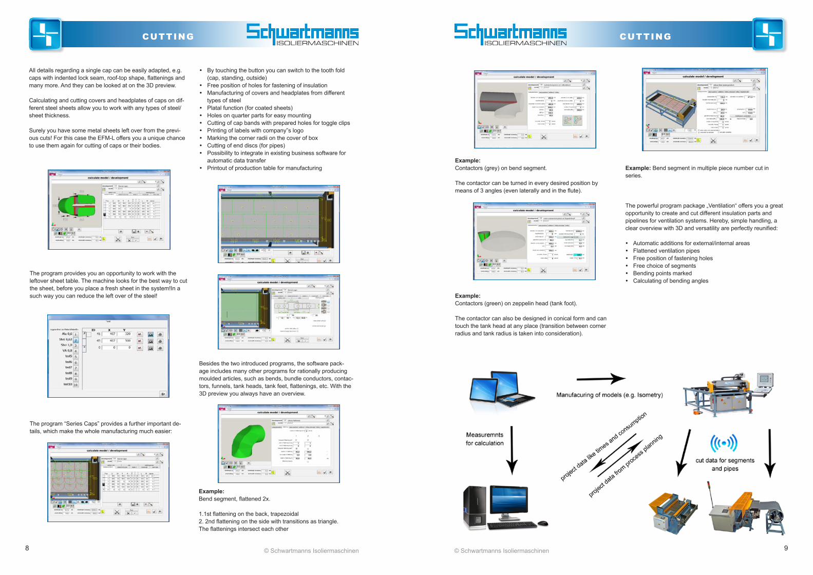
All details regarding a single cap can be easily adapted, e.g. caps with indented lock seam, roof-top shape, flattenings and many more. And they can be looked at on the 3D preview.
Calculating and cutting covers and headplates of caps on dif-ferent steel sheets allow you to work with any types of steel/sheet thickness.
Surely you have some metal sheets left over from the previ-ous cuts! For this case the EFM-L offers you a unique chance to use them again for cutting of caps or their bodies.
The program provides you an opportunity to work with the leftover sheet table. The machine looks for the best way to cut the sheet, before you place a fresh sheet in the system!In a such way you can reduce the left over of the steel!
The program “Series Caps” provides a further important de-tails, which make the whole manufacturing much easier:
y By touching the button you can switch to the tooth fold (cap, standing, outside)
y Free position of holes for fastening of insulation y Manufacturing of covers and headplates from different
types of steel y Platal function (for coated sheets) y Holes on quarter parts for easy mounting y Cutting of cap bands with prepared holes for toggle clips y Printing of labels with company”s logo y Marking the corner radii on the cover of box y Cutting of end discs (for pipes) y Possibility to integrate in existing business software for
automatic data transfer y Printout of production table for manufacturing
Besides the two introduced programs, the software pack-age includes many other programs for rationally producing moulded articles, such as bends, bundle conductors, contac-tors, funnels, tank heads, tank feet, flattenings, etc. With the 3D preview you always have an overview.
Example: Bend segment in multiple piece number cut in series.
Example: Contactors (grey) on bend segment.
The contactor can be turned in every desired position by means of 3 angles (even laterally and in the flute).
Example: Contactors (green) on zeppelin head (tank foot).
The contactor can also be designed in conical form and can touch the tank head at any place (transition between corner radius and tank radius is taken into consideration).
The powerful program package „Ventilation“ offers you a great opportunity to create and cut different insulation parts and pipelines for ventilation systems. Hereby, simple handling, a clear overview with 3D and versatility are perfectly reunified:
y Automatic additions for external/internal areas y Flattened ventilation pipes y Free position of fastening holes y Free choice of segments y Bending points marked y Calculating of bending angles

10 11© Schwartmanns Isoliermaschinen© Schwartmanns Isoliermaschinen
cuttingcutting
No. Description
100 Multiple elbows n
101 Elbow, free seam position n
102 Reserve bend n
103 Bend with welded segments n
104 Level, turned axis n
105 Bank of elbows, next to each other n
106 Bank of elbows, stacked n
107 Lyra elbow n
108 Cone elbow n
601 Pipe isometry n
141 Adapter piece, round - round n
142 Adapter piece, round – angular n
143 Adapter piece, round oval n
144 Adapter piece, round – angular 90° n
341 Cone, multi-section n
381 Sphere, small, with equal segments n
382 Ball great with misaligned segments n
221 Shock-cap-ring n
801 Tank-hull n
361 Pipe with ½ angled cuts n
181 Connecting piece Cylinder < - Cylinder n
182 Connecting piece Cylinder > - Cylinder n
183 Connecting piece Cylinder – Cone n
184 Connecting piece Cone – Cone n
185 Connecting piece Cone – Cylinder n
186 Connecting piece Cylinder – Back of bend n
188 Connecting piece Cylinder – Cylinder with a wedge
n
189 Connecting piece Cylinder – Cylinder with two wedges
n
192 Shoe connecting piece n
193 T-connector as adapter round-square n
194 Volumetrical connecting piece n
195 Connecting piece on tank n
251 Y fitting with cylindrical branches n
252 Y fitting with cone branches n
253 Y fitting with right-angled branches n
254 Y fitting with transfer legs n
271 Zeppelin head, clapper end/basket end/free form n
272 Cone head n
273 Domed head n
274 Dished head n
301 Cylinder fitting on Zeppelin head n
302 Cylinder fitting on cone head n
303 Cylinder fitting on sphere n
304 Cylinder fitting on ball n
305 Cone fitting on Zeppelin head n
306 Cone fitting on cone head n
307 Cone fitting on sphere n
308 Cone fitting on ball n
311 Cone, multi-section n
312 Rectangular fitting on cone head n
313 Rectangular fitting on sphere n
Programs especially for the rational series cutting of caps (boxes)201 Flange cap/end plate, horizontal n
202 Valve cap semicircular, horizontal n
203 Valve cap,angle, horizontal n
204 Rectangular cap semicircular, horizontal n
205 Rectangular cap angle, horizontal n
211 Flange cap, vertical n
212 Valve cap, semicircular, vertical n
213 Valve cap, angle, vertical n
214 Rectangular cap, semicircular, vertical n
215 Rectangular cap, angle, vertical n
220 Series caps (covers, cases, tapes, end plates) n
222 Heat exchanger n
Other special accessories441 Pipe smoothing device n
442 Bend smoothing device n
443 Fitting smoothing device n
450 Connecting piece – bend n
700 DXF n
800 Strip cutting device n
Programs especially for the insulation of ventilation systems400 Ventilation isometry n
401 Connecting piece n
402 Ventilation bend n
403 Ventilation angle pipe n
404 Ventilation transfer piece n
405 Ventilation pipe transfer piece n
406 Ventilation level n
407 Ventilation T-piece n
408 Ventilation Y-piece n
409 Ventilation channel n
n standard accessory n special accessory Selection of available programsn standard accessory n special accessory

12 13© Schwartmanns Isoliermaschinen© Schwartmanns Isoliermaschinen
cuttingcutting
Technical dataType FLEX-CUT 1 2
Band width mm 1020 1270
Sheet thickness mm 1,00 1,00
Smallest cut mm 275 275
Coil weight after drawing off from uncoiling device max. kg 500 500
after drawing off from the expansion mandrel bobbin. kg 2000 2000
Dimension (incl. coiler) L x B m 2,1 x 2,35 2,1 x 2,6
Compressed air supply min. bar 8,0 8,0
Connection voltage 3 x 400 V/50 Hz x x
Conical arrangement of the punch holes x x
Wireless connection with EFM-L x x
Net weight approx. kg 1025 1125Subject to constructional changes
Multifunctional cut-to-length lines type FLEX-CUT 1 and FLEX-CUT 2This machine is designed for sheet “cutting to length” - punching – beading for manufactur-ing insulation pipes and pre cutted blanks for the universal cutting machine type EFM-L. It is installed ready-for-connection on a profile steel frame, consisting of a 3-shaft bend feed and straightening unit, movable carriage for cutting to length and drawing-out machine.
The machine has a roller knife shears for cutting to length, two punching units to punch the screw holes, as well as a beading unit for beading the longitudinal seams on straight pipes.
The hole diameter is 3,3 mm. On request we offer other diameters. The left and right hole is continuously adjustable between 0 - 80 mm from the edge. Based on this conical punching at both sides is possible. As well as punching in two rows.
The beading unit is equipped with exchangeable beading wheels. Included is:
1 set = 2 pairs of beading wheels b = 4 mm 1 set = 2 pairs of beading wheels b = 7 mm
For both sides, the option with/without beadings and the depth of the beadings is continuously and separate adjustable.
An uncoiling device type CA 2 or CA 3 is included in a movable design.
Standard accessories
• Full-automatic sheet edge identification by light beam (no start cut necessary)
• Wireless connection included!
• Connection to universal cutting machine type EFM-L: By entering all necessary data into EFM-L (e.g. from isometry programs), FLEX-CUT automatically takes them over via wireless connection and starts to cut them due to calculated length and punches the fastening holes
• Left and right distance from the edge 0 - 80 mm (without beading) and 0 - 35 mm (with beading)
Control:
• High resolution touch panel
• Easy changeable languages
• Data entry up to 500 different cuttings in table form
• Up to 999 complex cutting routings can be stored into the database
Manual mode: For setting up, all functions can be executed manually, one at a time.
Automatic: preselectable: - Operation with/without punching - length of cutted blanks - number of pieces - positions of screw holes - Seam left / right side
FLEX-CUT 2
FLEX-CUT 2 (rear view)
Touch – sensitive 7” colour display. Multi language intuitive software interface for data entry of all needed parameters. For example input of diameter instead of length. Conical hole punching on both sides of the sheet. Double row punching.
4 Port W-LAN Router with WPA-2 encryption. For wired or wireless connection between FLEX-CUT and universal cutting machine EFM-L. The router can also be used for remote access support.

14 15© Schwartmanns Isoliermaschinen© Schwartmanns Isoliermaschinen
cuttingcutting
Wide strip cut-to-length line type KTE 1 and KTE 2
Ready-to-connect, mounted on profile steel frame, wide strip cut-to-length line with low space requirement.Consisting of: y Band feed and rough-aligning machine with rapid and
creep feed y Length measurement via shaft encoder y “Cut-to-length“ shears (eccentric plate shears for higher
working speed) y Pendulum coiler, movable, for small coils up to 500 kg and
outer Ø max. 500 mm
Special accessories• Additional movable coilers
• Special blade for chrome steel
• Hardened shafts for band feed and rough aligning machine
• Rubberized shafts for band feed and rough aligning machine
• Wireless connection to EFM-L
KTE 2
Technical dataType KTE 1 1-V 2 2-V
Band width mm 1020 1020 1270 1270
Sheet thickness mm 1,50 1,50 1,20 1,20
Smallest cut mm 10 10 10 10
Coil weight after drawing off from pendulum coiler max.
kg 300 300 300 300
after drawing off from the expansion mandrel bobbin.
kg 1000 1000 1000 1000
Dimension (incl. coiler) LxB m 2 x 2,2 2 x 2,2 2 x 2,5 2 x 2,5
Connection voltage 3x 400 V/50 Hz x x x x
Wireless connection with EFM-L x x
Net weight approx. kg 750 750 1080 1080 Subject to constructional changes
Type KTE 1-V and KTE 2-V(V= wireless connection with EFM-L)
This option helps to optimize the manufacturing of both ma-chines: by entering all necessary data into EFM-L (e.g. from isometry programs), KTE automatically takes them over via wireless connection and starts to cut them due to entered length.
Manual plate shears type WST 1
The advantages of these light building plate shears with the precision of the heavy workshop versions are excellently uni-fied in these manual plate shears: High-quality blades out of Swedish steel ensure a perfect cut. The blade base can be variably adjusted and is held in place by maintenance-free bearings.
The support table with perpendicular contact strip is especially large.Through the open sheet holding-down device, which can be swung out, cuts of any length are possible in push-through process.
A width stop, which can be adjusted in parallel, with an in-serted millimetre scale, guarantees that setting is fast and pre-cise. The resiliently arranged stop support makes it possible to even cut narrow strips with no problems.
Cutting devices for adapting pipe segments type ZSV 1 and ZSV 2
This device is specially designed for the rational cutting of adapting pipe segments from insulation pipes.
By means of electrically-operated shears with double-sided cut, burr-free cutting is guaranteed without deforming the cutting edges. Its low weight is ideal for the building site. The quickly dismountable feet make transportation easier.
Special version• Table width 200 mm
• Without base
Special version
• Attachment fixture for our building site beading machine, type SMW 50.00 or SMW 50.20
Special accessories• Special blades for VA-sheets
• Parallel table stop
• Transport device for safe transport with forklift or lifting truck
Technical dataWorking length mm 1020
Cutting performance steel (400 N/mm²)
mm 1,5
Width stop adjustable from mm 0 - 550
Table width mm 680
Length of angular table stop mm 660
Net weight approx. kg 230Subject to constructional changes
Technical dataType ZSV 1 ZSV 2
Working length mm 1050 1300
For steel sheets up to mm 1,25 1,25
Motor preselection according to scale
mm 50 - 1000 50 - 1250
Connection voltage, AC 230 230
Net weight approx. kg 27 35 Subject to constructional changes
ZSV 1
WST 1
Infinitely adjustable sheet guidance with spindle, 0 - 1250 mm
NEW! operator panel with 5,7“ touch-screen for data input

16 17© Schwartmanns Isoliermaschinen© Schwartmanns Isoliermaschinen
cuttingcutting
Technical dataType KSH 1 KSH 3
Sheet thickness mm 1,5 1,5
Round blank diameter mm 70 -1000 70 - 1500
Blade overhang mm 350 350
Net weight approx. kg 128 150
Subject to constructional changes
KSH 1
KSM 3
The manually operated circular shears distinguish themselves by their easy operability.
Interior and exterior contours are cut cleanly. It is Driving powern by a handcrank on the top shaft. The round blank diameter is set according to the dimension scale. The blade is advanced by means of a handwheel and spindle.
The cut gap can be adjusted quickly and easily by means of a setting ring with scale.
The blade shafts are held in place by maintenance-free bear-ings.
Special accessories• Special blades for VA-sheets
• Transport device for safe transport with forklift or lifting truck.
Standard accessories• Base
• Foot switch
Special accessories• Special blades for VA-sheets
• Transport device for safe transport with forklift or lifting truck.
Circular shears with motor drive type KSM 1 and KSM 3
The Driving power, controlled via foot jogging switch, is a transmission brake motor with 2 working speeds.
Interior and exterior contours are cut cleanly. The round blank diameter is set according to the dimension scale. The blade is advanced by means of a handwheel and spindle.
The cut gap can be adjusted quickly and easily by means of a setting ring with scale.
The blade shafts are held in place by maintenance-free bear-ings.
Technical dataType KSM 1 KSM 3
Sheet thickness mm 1,5 1,5
Round blank diameter mm 70 - 1000 70 - 1500
Blade overhang mm 350 350
Working speed m/min 7 /14 7 / 14
Driving power kw 0,3/0,45 0,3 / 0,45
Connection voltage 3x400V / 50Hz
x x
Net weight approx. kg 155 178 Subject to constructional changes
Standard accessories
• Special cutter wheels
• 2 large stop plates with additional one-sided preset pre-screwing plate for small or larger stop depths
Pipe-cutting machines type SMA 80 SK
A further development of our proven motorized beading machine, type SMA 80, specially for cutting welded stainless steel pipes to length. It is powered by a pole changing motor (thermally protected) via V-belt and worm gear running in the oil bath. The optimal run-through speed can be selected from 4 different working speeds.Thanks to a massive base plate, the machine can be set up without any additional fixation.The height of the top shaft is adjusted by means of the hydraulic Driving power. Adjustable stops on the hydraulic cylinder limit the path of the top shaft. A cut with low contortion is guar-anteed by supporting rings on the bottom shaft (behind the special cutter roller).
The control takes place via a double foot switch. The machine is started by pressing the left foot switch, and the cutter roller mounted to the top shaft is lowered to the cutting position. After ending the cutting process, the right foot switch is pressed: The top shaft swivels back to its original position, and the machine Driving power shuts down.
Technical dataSheet thickness (stainless steel) mm 0,4 - 1,0
Smallest pipe diameter mm 100
Overhang mm 530
Working speed m/min 5 / 7 / 10 / 14
Driving power (400 V three-phase current) kw 2,0 / 2,4
Connection voltage 3x 400 V/50 Hz x
Net weight approx. kg 240
Subject to constructional changes
Circular shears with manual drive type KSH 1 and KSH 3

18 19© Schwartmanns Isoliermaschinen© Schwartmanns Isoliermaschinen
roundingrounding
Folding machines type ABL 2 and ABL 3
This universal folding, lock seam and turning-in machine is equally suitable for edging, lock-seaming, roll bending and offsetting as well as for turning in steel sheets with up to 1270 mm usable area and up to 1.25 mm sheet thickness.
The machine support consists of two strong side parts made of high-quality machine casting and a closed, breakage-free steel base.
The side parts are for taking on the three cheeks and the top cheek engine. The upper and lower cheeks are made of a closed steel construction, and the bending cheek is manufac-tured from whole steel.
The high opening width of the top cheek allows work to be done with all different kinds of edging rails (angular rails, retaining clamp rails, radius rails). Thanks to the laterally at-tached angular stop, identical bending angles are guaranteed.
For radius work, the bending cheek is sufficiently adjustable. A gas pressure telescope spring facilitates the bending process.
It is possible to manufacture narrow offsets by means of 2 exchangeable insert rails.
The top cheek Driving power is Driving powern by handwheel via bevel Driving power on trapezoidal threaded spindles. This kind of clamping also allows work with loose inserts (espe-cially advantageous for training workshops).
All bearings are equipped with maintenance-free, dry plain bearings.
Special accessories• Sharp rails 15° und 20°
• Round rails 1.5 - 20 mm radius
• Retaining clamp and angular rails
• Width stop of 8 - 500 mm
• Transport device for safe transport with forklift or lifting truck
Standard accessories• 1 sharp rail 45°
• 1 round rail R = 3 mm
• 1 bending cheek rail 40/10
• 1 bending cheek rail 40/20
Technical dataType ABL 2 ABL 3
Working length mm 1020 1270
Sheet thickness mm 1,50 1,25
Port opening of top clamp bar mm 90 90
Highest working-height of top clamp bar mm 70 70
Adjustment for bending flange mm 40 40
Lowest flanging height (in sheet thickness) 8 x 8 x
Net weight approx. kg 160 240 Subject to constructional changes
ABL 2
Technical dataType WSRN 35.04
Working length mm 420
Sheet thickness up to mm 1,00
Shaft diameter, top shaft mm 35
Net weight approx. kg 60 Subject to constructional changes
Roll bending machines with manual drive type WSRN 01.1 and WSRN 02.1
These roll bending machines are suitable for workshops, on building sites and in schools due to their robust construction, easy handling and low weight.
They are manually operated by a handcrank directly on the bottom shaft. The working shafts are arranged asymmetrically, spherically turned. They are held in place by maintenance-free dry plain bearings. The top shaft can be swung out toward the front. The clutch and gears are to the left, so that even narrow pipes can be easily pulled off.
The top shaft is locked by a closed blocking bearing (single handed operation). The bottom and back shafts can be ad-justed from the right, outer side of the machine. The back shaft advances via ratchet lever and tooth segment. The settings can be easily reproduced via the sensitive tooth segment. The back shaft can be tilted for conical rounding.
Standard accessories• Base
Special accessories• Lock seam groove
• Grooves for laying wires
Technical data Type WSRN 01.1 WSRN 02.1
Working length mm 1020 1020
Sheet thickness bis mm 0,80 1,00
Shaft diameter mm 45 50
Net weight approx. kg 90 97 Subject to constructional changes
WSRN 35.04
WSRN 01.1
Roll bending machines with manual drive type WSRN 35.04These machines are designed for manufacturing parts with small diameters. Depending on the material and sheet thickness, diam-eters as small as approx. 40 mm can be manufactured.
Robust construction, easy handling! The working shafts are arranged asymmetrically and are held in place by maintenance-free bearings. The top shaft can be swung out toward the front and is locked by a closed blocking bearing, which is why there is one-hand operation. The bot-tom and the back shaft advances via ratched lever and tooth segment. Manual operation by means of a crank on the lower shaft.

20 21© Schwartmanns Isoliermaschinen© Schwartmanns Isoliermaschinen
roundingrounding
Roll bending machines with back gear and manual drive type WSRV 03.1 - WSRV 04.3These robustly constructed roll bending machines are espe-cially suitable for use in workshops and on building sites. They are powered by a changeable manual crank directly on the bottom shaft.
The working shafts are arranged asymmetrically, spherically turned, and are held in place by maintenance-free, dry plain bearings. The top shaft can be swung out toward the front. This shaft is locked with a closed blocking bearing. The back gear and the clutch gears are to the left, so that even narrow pipes can be easily pulled off.
The top shaft is locked by a closed blocking bearing (one-hand operation). The bottom and back shafts can be adjusted from the right, outer side of the machine. The back shaft advances via ratchet lever and tooth segment. The settings can be easily reproduced via the sensitive tooth segment. The back shaft can be tilted for conical rounding.
Technical dataType Shaft-Ø
in mm Working length in
mm
Sheet thickness
in mm
Net weight approx.
in kg WSRV 05.1 75 1020 2,00 310 WSRV 05.2 75 1270 1,75 350 WSRV 05.3 75 1520 1,50 390 WSRV 05.4 75 2020 0,75 450 WSRV 06.1 80 1020 2,25 335 WSRV 06.2 80 1270 2,00 380 WSRV 06.3 80 1520 1,75 425 WSRV 06.4 80 2020 1,00 470 WSRV 07.1 85 1020 2,50 360 WSRV 07.2 85 1270 2,25 410 WSRV 07.3 85 1520 2,00 460 WSRV 07.4 85 2020 1,25 510 Subject to constructional changes
Technical dataType Shaft-Ø
in mmWorking length in
mm
Sheet thickness
in mm
Net weight approx. in
kgWSRV 03.1 55 1020 1,25 140
WSRV 03.2 55 1270 1,00 165
WSRV 04.1 65 1020 1,50 160
WSRV 04.2 65 1270 1,25 185
WSRV 04.3 65 1520 1,00 218 Subject to constructional changes
Roll bending machines with back gear and manual drive type WSRV 05.1 - WSRV 07.4
These roll bending machines with a working length of 1-2 me-ters and roller diameters of 75-85 mm are powered via manual crank on back gear. The working shafts are arranged asymmetrically, spherically turned, and are held in place by maintenance-free dry plain bearings. The top shaft can be swung out toward the front. This shaft is locked with a closed blocking bearing.The back gear and the clutch gears are to the left, so that even narrow pipes can be easily pulled off. The offsets of the bottom and back shafts are arranged on the right outer side of the machine.The back shaft is continuously adjusted via handwheel and worm gear.The setting can be reproduced via position indicator.
WSRV 05.4
WSRV 03.1
Roll bending machines with motor drive type WSRM 03.1 - WSRM 04.3These roll bending machines are standardly equipped with a Driving power for 2 working speeds and with a 3-shaft Driving power.The machine is driven by a pole-changing transmission brake motor over chain transmission to the back gears. The Driving power motor is thermally protected at both speeds.
The electric safety control is equipped with: Foot switch with integrated EMERGENCY STOP function for forward and reverse EMERGENCY STOP rip cords on the front and back sides of the machine.
The main switch, the manual switch for the speed preselection as well as the CEE plug connection with phase reverser are in the control cabinet.
The working shafts are arranged asymmetrically, spherically turned, and are held in place by maintenance-free dry plain bearings. The top shaft can be swung out toward the front and is locked by a closed blocking bearing. The back gear and the clutch gears are to the left, so that even narrow pipes can be easily pulled off.
Technical dataType Shaft-Ø in mm Working length in mm Sheet thickness in mm Net weight approx. in kg
WSRM 03.1 55 1020 1,25 175
WSRM 03.2 55 1270 1,00 215
WSRM 04.1 65 1020 1,50 180
WSRM 04.1 / 45 65 1020 0,80 180
WSRM 04.2 65 1270 1,25 230
WSRM 04.3 65 1520 1,00 280For all types: Working speed: 6 /12 m/min Connection voltage: 3x 400V / 50 Hz Driving power: 0,75 / 1,1 KW
Subject to constructional changes
Special accessories• Continuously adjustable back shaft via handwheel with position indicator (see figure)
• Other working speeds
• Transport device for safe transport with forklift or lifting truck
• Shaft finger protection
Working shafts in special version • naturally hard, approx. 1000 N/mm²
• hardened
• mat chronium plated
• rubberized
• plastic-coated
WSRM 04.2
Continuously adjustable back shaft via handwheel
Ratched lever and tooth segment
Standard accessories• Base
Special accessories• Continuously adjustable back shaft via handwheel with
position indicator (see figure on page 21)• Transport device for safe transport with forklift or lifting
truck
• Lock seam groove
• Grooves for laying wires

22 23© Schwartmanns Isoliermaschinen© Schwartmanns Isoliermaschinen
beading / flangingrounding
Technical dataType Shaft-Ø in mm Working length in mm Sheet thickness in mm Net weight approx.
in kg
WSRM 05.1 75 1020 2,00 340
WSRM 05.2 75 1270 1,75 380
WSRM 05.3 75 1520 1,50 420
WSRM 05.4 75 2020 0,75 470
WSRM 06.1 80 1020 2,25 355
WSRM 06.2 80 1270 2,00 400
WSRM 06.3 80 1520 1,75 445
WSRM 06.4 80 2020 1,00 490
WSRM 07.1 85 1020 2,50 380
WSRM 07.2 85 1270 2,25 430
WSRM 07.3 85 1520 2,00 480
WSRM 07.4 85 2020 1,25 530 For all types: Working speed: 4 /8 m/min Connection voltage: 3x 400V / 50 Hz Driving power: 1,0 / 1,4 KW
Subject to constructional changes
Roll bending machines with motor drive type WSRM 05.1 - WSRM 07.4These roll bending machines with a working length of 1- 2 meters and roller diameter of 75 - 85 mm are standardly equipped with a driving power for two working speeds. The machine is driving powered by a pole-changing transmission brake motor over a chain transmission to the back gears. The Driving power motor is thermally protected at both speeds.
The electric safety control is equipped with:- Foot switch with integrated EMERGENCY STOP - Function for forward and reverse. - EMERGENCY STOP rip cords on the front and back sides of the machine.
The main switch, the manual switch for the speed preselection as well as the CEE plug connection with phase reverser, are in the control cabinet. The working shafts are arranged asymmetrically, spherically turned. They are held in place by maintenance-free dry plain bearings. The top shaft can be swung out toward the front and is locked by a closed blocking bearing. The reverse gear and the clutch are to the left, so that even narrow pipes can be easily pulled off.
Special accessories• 3-Shaft driving power
• Other working speeds
• Shaft finger protection
• Positioning of the back shaft with motor driving power by means of 1-axis CNC microprocessor control
Working shafts in special version• naturally hard, approx. 1000 N/mm²
• hardened
• matt chromium plated
• rubberized
• plastic-coated
WSRM 05.4
Standard accessories• 1 set of normal wheels, cosisting of:
1 pair of swaging wheels V1, V2, V3 1 pair of flanging wheels B 1 pair of closing wheels Z 1 pair of box wheels U
• 1 wheel wrench
These two machines with their robust construction are de-signed for hard workshop use. The machine bodies are made of special machine casting in a closed design.They are driven by a manual crank on the bottom shaft, so that the crank and workpiece move synchronously.
The wheel is adjusted by shifting or swivelling the top shaft. Through this, corrections can be completely followed, even during operation. The large-sized stop plate is equipped with a hardened pre-screwing plate. All bearings are maintenance-free.
Special accessories• Frame base
• Divided pre-screwing plate
• T-piece guide
• Special wheels
Technical dataType SMW
50.02 SMW 56.02
Sheet thickness mm 1,0 1,25
Wheel centre distance mm 50 56
Overhang (greatest working depth)
mm 195 225
Net weight approx. kg 33 35 Subject to constructional changes
Beading and flanging machines with manual drive type SMW 50.02 and SMW 56.02
SMW 56.02
Beading and flanging machine with manual drive type SMW 50.00This light and compact machine is specially designed for going away on construction jobs. The fastening possibili-ties, by means of pipe clamps on scaffolding pipes with 50 mm Ø or by means of screw clamps, make the machine universally usable.
With an attached fixture, the machine can be mounted to our adapting pipe segment cutting device type ZSV. This combi-nation is ideal for use on building sites.
The machine body is manufactured from aluminium. The beading shafts are held in place by maintenance-free needle roller bearings. This guarantees smooth running.The bottom shaft is axially adjustable and the height of the top shaft can be adjusted. The stop plate is hardened.
Standard accessories• Pipe clamp
• 2 pair of wiring wheels: V 0, b = 3 mm
V 1, b = 4 mm
• 1 wheel wrench
Special accessories• Foot for fastening by means of screw clamp or vice
• Other wheels
• Attachment fixture for cutting device for adapting pipe segments ZSV
Technical dataSheet thickness mm 0,8
Wheel centre distance mm 50
Overhang mm 60
Net weight approx. kg 8Subject to constructional changes

24 25© Schwartmanns Isoliermaschinen© Schwartmanns Isoliermaschinen
beading / flanging beading / flanging
This light and compact machine is specially designed for go-ing away on construction jobs.
- 230V / 50Hz Alternate current - Weel center distance: 50mm - Overhang: 60mm - Sheet thickness: 1.0mm - Working speed: 7m/Min - Weight: approx. 13 Kg - incl. 2 pairs of wiring wheels V0 and V1
The fastening possibilities, by means of pipe clamps on scaf-folding pipes with 50 mm Ø or by means of screw clamps, make the machine universally usable.
With an attached fixture, the machine can be mounted to our adapting pipe segment cutting device type ZSV. This combina-tion is ideal for use on building sites.
The machine body is manufactured from aluminium. The beading shafts are held in place by maintenance-free needle roller bearings. This guarantees smooth running.The bottom shaft is axially adjustable and the height of the top shaft can be adjusted. The stop plate is hardened.
Beading and flanging machines with motor drive type SMW 50.20
SMW 50.20
Standard accessories• Pipe clamp
• 2 pair of wiring wheels: V 0, b = 3 mm
V 1, b = 4 mm
• 1 wheel wrench
Technical dataSheet thickness mm 1,0
Wheel centre distance mm 50
Overhang mm 60
Connecting voltage, AC V 230
Driving power kW 1,02
Continuously adjustable working speed up to approx. m/min m/min 8
Net weight approx. kg 13
Subject to constructional changes
These machines are light motor machine versions for use on building sites.
The machine bodies are made of special machine casting in a closed design.
The roller is adjusted by shifting or swivelling the top shaft. Through this, corrections can be made, even during operation.
The large-sized stop plate is equipped with a hardened pre-screwing plate.
All bearings are maintenance-free.
They are driven via a (2 speed) pole-changing angular gear brake motor. The machine is controlled via a movable foot jog-ging switch.
The types SMW 50.22 „C“ and SMW 56.22 „C“ are equipped with a 230 V AC drive. The run-through speed can be continu-ously regulated with the foot switch (even during operation). The electric control is installed in the box frame (standard).
Beading, flanging and wire insert machines with motor drive type SMW 50.22/C and SMW 56.22/C
Special accessories• Drive 230 V Alternating current for 1 operating speed
• Box frame
• Divided pre-screwing plate
• T-piece guide
• Special wheels
• Holder for wheels
• Movable design (see figure page 26)
Standard accessories• Power supply via CEE coupling 16A with integrated phase
inverter
• 1 set of normal wheels, each consisting of:
1 pair of swaging wheels V1, V2, V3 1 pair of flanging wheels B 1 pair of closing wheels Z 1 pair of box wheels U
• 1 wrench wheel
Technical dataType SMW 50.22 SMW 56.22 SMW 50.22 C SMW 56.22 C
Sheet thickness mm 1,00 1,25 1,00 1,25
Wheel centre distance mm 50 56 50 56
Overhang (greatest working depth) mm 195 225 195 225
Working speed m/min 6,5 / 13 7,0 / 14 2,0 - 20 2,0 - 20
Connection voltage 3x 400 V 50 Hz x x
Connection voltage, AC 230 V x x
Driving power kW 0,3 / 0,45 0,3 / 0,45 0,55 0,55
Net weight approx. kg 42 43 75 76
Subject to constructional changes
SMW 56.22
SMW 56.22 with box frame
Special accessories
• Foot for fastening by means of screw clamp or vice
• Other wheels
• Attachment fixture for cutting device for adapting pipe segments ZSV
SMW 50.20 on attachment fixture for cutting device type ZSV

26 27© Schwartmanns Isoliermaschinen© Schwartmanns Isoliermaschinen
beading / flanging beading / flanging
These machines are designed as table machines. They are suitable for the workshop, as well as for the building site, due to their light weight. The machine bodies are made of special machine casting in a closed design.
The electric control and a tool compartment are installed in the aluminium machine base.The roller is adjusted by shifting or swivelling the top shaft. Through this, corrections can be completely followed, even during operation. The large-sized stop plate is equipped with a hardened pre-screwing plate. All bearings are maintenance-free.
They are driven via a pole-changing (for 2 speeds) angular gear brake motor. The machine can be operated either in jog mode (clockwise/counter-clockwise motion) or in continuous mode (only one direction) via the foot reversing switch.
To make transportation easier, foot-switch cables and power supply cables can be separated from the machine via plug connections.
Beading and flanging machines with motor drive type S 50-ISO/T and S 56-ISO/T
Special accessories• Wheels in all versions
• Box frame
• Flanging device
• T-piece guide
• Other working speeds
• Holder for wheels
• Movable design
Standard accessories• Large stop plate with hardened pre-screwing plate
• Foot switch with multi-pin plug
• Power supply via CEE coupling 16 A with integrated phase inverter
• wheel wrench
Technical data
Type S 50-ISO/T S 56-ISO/T
Sheet thickness mm 1,25 1,25
Wheel centre distance mm 50 56
Overhang mm 170 210
Working speed approx. m/min 6 / 12 6,7 / 13,4
Connection voltage 3x 400 V/50 Hz x x
Driving power kW 0,7 / 0,85 0,7 / 0,85
Net weight approx. kg 65 67
Subject to constructional changes
S 56-ISO/T
Movable design with mobile trolley stand
Example shows type SMW 56.22
Technical dataType SMA 56 SMA 80 SMA 56 C SMA 80 C
Sheet thickness mm 1,50 2,00 1,50 2,00
Wheel centre distance mm 56 80 56 80
Overhang mm 260 315 260 315
Working speed m/min 5 / 8 / 10 / 16 5 / 7 / 10 / 14 2 - 20 2 - 20
Connection voltage 3x 400V 50 Hz x x x x
Driving power kW 1,3 / 1,7 2,0 / 2,4 1,7 2,4
Net weight approx. kg 120 200 150 230 Subject to constructional changes
Beading and flanging machines with motor drive type SMA 56/C and SMA 80/CThese machines are designed for workshop use due to their robust construction.The machine bodies are made of special machine casting in a closed design.
A massive base plate makes it easier to set-up the machine. No additional fixtures are necessary.
It is driven by an internal pole-changing brake motor (thermally protected) via V-belts and worm gear running in an oil bath.
The safety control, with EMERGENCY STOP switch and CEE plug connection (16 Amp.) with integrated phase reverser, as well as the selection switches for jogging/continuous mode and speed preselection are located at the foot of the machine.
The roller is adjusted by shifting or swivelling the complete bearings of the top shaft. Through this, corrections are pos-sible and can be completely followed, even during operation. The large-sized stop plate is equipped with a hardened pre-screwing plate. All bearings are maintenance-free.
For types SMA 56 „C“ and SMA 80 „C“, the working speed is electronically controlled.
The desired speed for the respective operation can be prese-lected with a rotary potentiometer. Full torque is guaranteed for a working speed 2 m/min and higher.
SMA 56
SMA 80
Standard accessories• Large stop plate with hardened pre-screwing plate
• Electric safety control
• Foot switch
• CEE-coupling 16 Amp with integrated phase inverter
• Wheel wrench
Special accessory only for SMA 80 / SMA 80 C:• Special set of wheels (3 pairs) for the folded seam
connection to tank heads
28 29© Schwartmanns Isoliermaschinen© Schwartmanns Isoliermaschinen
beading / flanging flanging
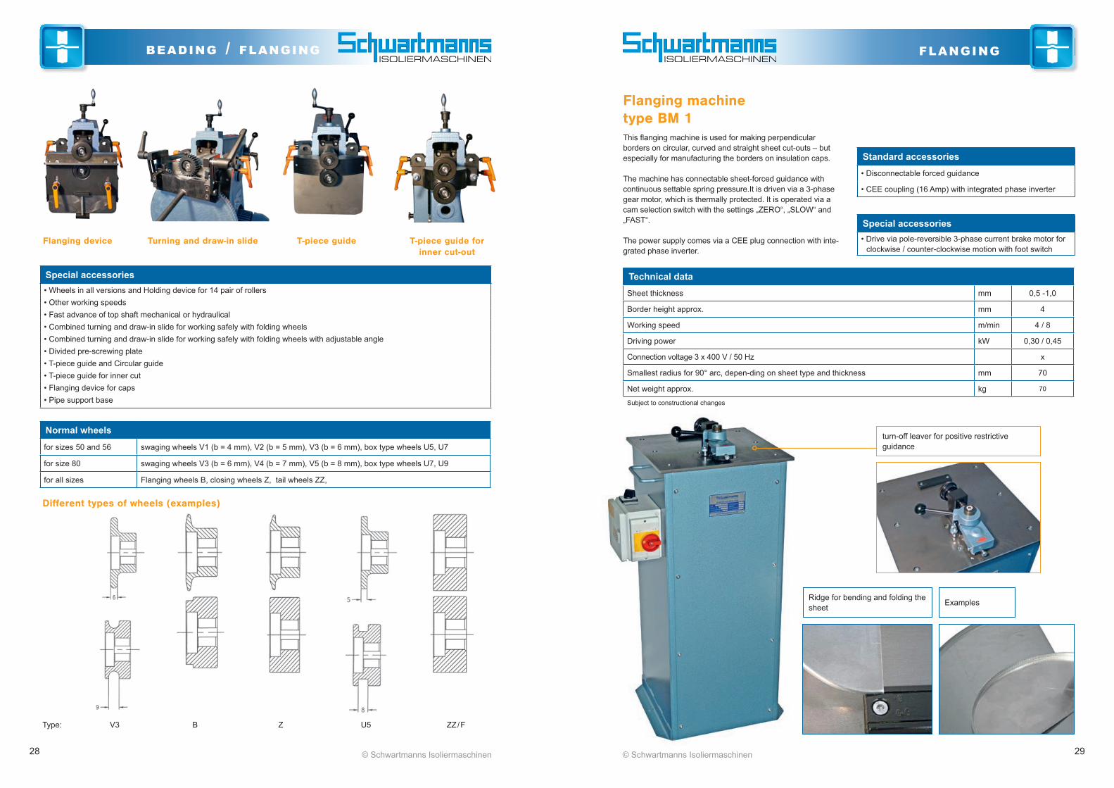
Special accessories• Wheels in all versions and Holding device for 14 pair of rollers• Other working speeds• Fast advance of top shaft mechanical or hydraulical• Combined turning and draw-in slide for working safely with folding wheels• Combined turning and draw-in slide for working safely with folding wheels with adjustable angle• Divided pre-screwing plate• T-piece guide and Circular guide• T-piece guide for inner cut• Flanging device for caps• Pipe support base
Normal wheels
for sizes 50 and 56 swaging wheels V1 (b = 4 mm), V2 (b = 5 mm), V3 (b = 6 mm), box type wheels U5, U7
for size 80 swaging wheels V3 (b = 6 mm), V4 (b = 7 mm), V5 (b = 8 mm), box type wheels U7, U9
for all sizes Flanging wheels B, closing wheels Z, tail wheels ZZ,
Flanging device Turning and draw-in slide T-piece guide T-piece guide for inner cut-out
Different types of wheels (examples)
Type: V3 B Z U5 ZZ / F
Technical dataSheet thickness mm 0,5 -1,0
Border height approx. mm 4
Working speed m/min 4 / 8
Driving power kW 0,30 / 0,45
Connection voltage 3 x 400 V / 50 Hz x
Smallest radius for 90° arc, depen-ding on sheet type and thickness mm 70
Net weight approx. kg 70
Subject to constructional changes
Flanging machine type BM 1This flanging machine is used for making perpendicular borders on circular, curved and straight sheet cut-outs – but especially for manufacturing the borders on insulation caps.
The machine has connectable sheet-forced guidance with continuous settable spring pressure.It is driven via a 3-phase gear motor, which is thermally protected. It is operated via a cam selection switch with the settings „ZERO“, „SLOW“ and „FAST“.
The power supply comes via a CEE plug connection with inte-grated phase inverter.
Standard accessories• Disconnectable forced guidance
• CEE coupling (16 Amp) with integrated phase inverter
Special accessories• Drive via pole-reversible 3-phase current brake motor for
clockwise / counter-clockwise motion with foot switch
Ridge for bending and folding the sheet Examples
turn-off leaver for positive restrictive guidance

30 31© Schwartmanns Isoliermaschinen© Schwartmanns Isoliermaschinen
punching punching
Rectilinear punching machines with manual drive type RLH 1 and RLH 2Rectilinear punching machine for rationally punching holes in cuts for sheet insulation.
It is driven via hand lever and eccentric shaft. The punching units serve to take up the hole cuts (stamps and matrices) and are arranged on the machine table so they can be shifted. The number of punching units and the diameter of the hole cuts (2.5 - 6.0 mm) can be adapted to the respective needs.
The distance of the holes from the edge of the sheet (overlap-ping) is continuously adjustable by width stops. A variable pull-out table extension guarantees stable support for the sheets to be hole-punched.
Technical dataType RLH 1 RLH 2
Working length mm 1020 1270
Sheet thickness mm 1,2 1,0
Punching units piece 6 6
Hole cut mm 3,3 3,3
Overhang of punching units mm 40 40
Smallest hole distance mm 60 60
Net weight approx. kg 110 130
Subject to constructional changes
RLH 1
Rectilinear punching machines with foot drive type RLF 1 and RLF 2Rectilinear punching machine for rationally punching holes in cuts for sheet insulation.
This is driven by means of a foot pedal. The punching units serve to take up the hole cuts (stamps and matrices) and are arranged on the machine table so they can be shifted. The number of punching units and the diameter of the hole cuts (2.5 - 6.0 mm) can be adapted to the respective needs.
The distance of the holes from the edge of the sheet (overlap-ping) is continuously adjustable by width stops. A variable pull-out table extension guarantees stable support for the sheets to be hole-punched.
Standard accessories• 1 Length stop
• 3 width stops
• Pull out table extention
Special accessories RLF 1 and RLF 2• Design for punching sheets of any length in push-through
processes, incl. extended stop rail with 2 adjustable length stops
• Additional complete punching units with hole cuts
• Reinforced design, for hole cuts larger than 4.0 mm, when there are more than 6 punching units or for chromium steel sheets thicker than 0.8 mm
• Fixed stops for overlapping 12,5 / 15 / 25 mm
Technical dataType RLF 1 RLF 2
Working length mm 1020 1270
Sheet thickness mm 1,2 1,0
Punching units piece 6 6
Hole size mm 3,3 3,3
Overhang of punching units mm 40 40
Smallest hole distance mm 60 60
Net weight approx. kg 120 140
Subject to constructional changes
RLF 1
Fixed stops for overlapping
Standard accessories• 1 Length stop
• 3 width stops
• Pull out table extention
Special accessories RLH 1 and RLH 2• Design for punching sheets of any length in push-through
processes, incl. extended stop rail with 2 adjustable length stops
• Additional complete punching units with hole cuts
• Reinforced design, for hole cuts larger than 4.0 mm, when there are more than 6 punching units or for chromium steel sheets thicker than 0.8 mm
• Fixed stops for overlapping 12,5 / 15 / 25 mm
32 33© Schwartmanns Isoliermaschinen© Schwartmanns Isoliermaschinen
punching punching
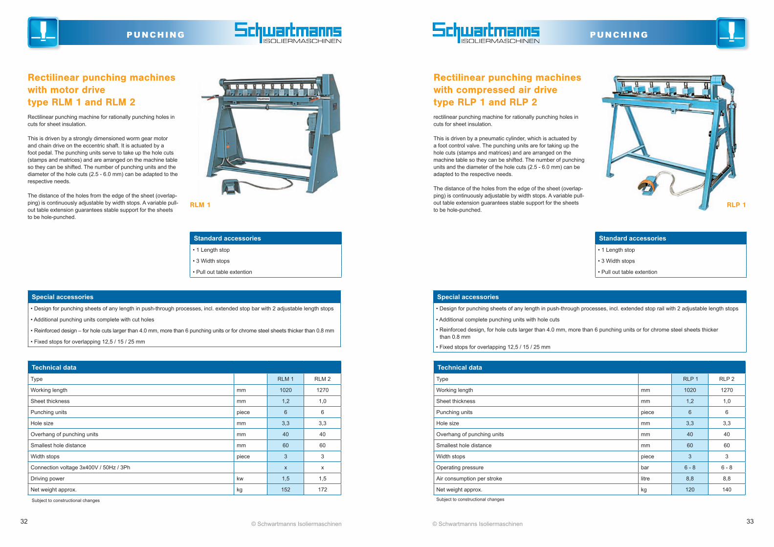
Rectilinear punching machines with motor drive type RLM 1 and RLM 2Rectilinear punching machine for rationally punching holes in cuts for sheet insulation.
This is driven by a strongly dimensioned worm gear motor and chain drive on the eccentric shaft. It is actuated by a foot pedal. The punching units serve to take up the hole cuts (stamps and matrices) and are arranged on the machine table so they can be shifted. The number of punching units and the diameter of the hole cuts (2.5 - 6.0 mm) can be adapted to the respective needs.
The distance of the holes from the edge of the sheet (overlap-ping) is continuously adjustable by width stops. A variable pull-out table extension guarantees stable support for the sheets to be hole-punched.
Standard accessories• 1 Length stop
• 3 Width stops
• Pull out table extention
Special accessories• Design for punching sheets of any length in push-through processes, incl. extended stop bar with 2 adjustable length stops
• Additional punching units complete with cut holes
• Reinforced design – for hole cuts larger than 4.0 mm, more than 6 punching units or for chrome steel sheets thicker than 0.8 mm
• Fixed stops for overlapping 12,5 / 15 / 25 mm
Technical dataType RLM 1 RLM 2
Working length mm 1020 1270
Sheet thickness mm 1,2 1,0
Punching units piece 6 6
Hole size mm 3,3 3,3
Overhang of punching units mm 40 40
Smallest hole distance mm 60 60
Width stops piece 3 3
Connection voltage 3x400V / 50Hz / 3Ph x x
Driving power kw 1,5 1,5
Net weight approx. kg 152 172
Subject to constructional changes
RLM 1
Standard accessories• 1 Length stop
• 3 Width stops
• Pull out table extention
Special accessories• Design for punching sheets of any length in push-through processes, incl. extended stop rail with 2 adjustable length stops
• Additional complete punching units with hole cuts
• Reinforced design, for hole cuts larger than 4.0 mm, more than 6 punching units or for chrome steel sheets thicker than 0.8 mm
• Fixed stops for overlapping 12,5 / 15 / 25 mm
Rectilinear punching machines with compressed air drive type RLP 1 and RLP 2rectilinear punching machine for rationally punching holes in cuts for sheet insulation.
This is driven by a pneumatic cylinder, which is actuated by a foot control valve. The punching units are for taking up the hole cuts (stamps and matrices) and are arranged on the machine table so they can be shifted. The number of punching units and the diameter of the hole cuts (2.5 - 6.0 mm) can be adapted to the respective needs.
The distance of the holes from the edge of the sheet (overlap-ping) is continuously adjustable by width stops. A variable pull-out table extension guarantees stable support for the sheets to be hole-punched.
Technical dataType RLP 1 RLP 2
Working length mm 1020 1270
Sheet thickness mm 1,2 1,0
Punching units piece 6 6
Hole size mm 3,3 3,3
Overhang of punching units mm 40 40
Smallest hole distance mm 60 60
Width stops piece 3 3
Operating pressure bar 6 - 8 6 - 8
Air consumption per stroke litre 8,8 8,8
Net weight approx. kg 120 140
Subject to constructional changes
RLP 1
34 35© Schwartmanns Isoliermaschinen© Schwartmanns Isoliermaschinen
punching punching
Special accessories• Additional complete punching units with hole cuts
• Other hole sizes on request
Technical dataWorking length mm 1020
Sheet thickness mm 1,2
Punching units piece 6
Hole size mm 3,3
Overhang of punching units mm 25
Smallest hole distance 1st and 2nd hole mm 25
Hole distance otherwise mm 40
Operating pressure bar 6
Net weight approx. kg 100
Subject to constructional changes
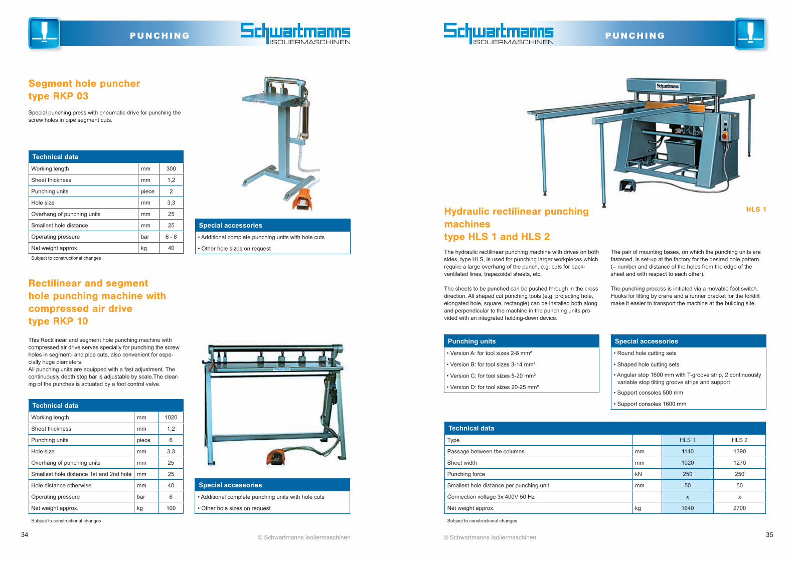
This Rectilinear and segment hole punching machine with compressed air drive serves specially for punching the screw holes in segment- and pipe cuts, also convenient for espe-cially huge diameters. All punching units are equipped with a fast adjustment. The continuously depth stop bar is adjustable by scale.The clear-ing of the punches is actuated by a foot control valve.
Rectilinear and segment hole punching machine with compressed air drive type RKP 10
Special accessories• Additional complete punching units with hole cuts
• Other hole sizes on request
Technical dataWorking length mm 300
Sheet thickness mm 1,2
Punching units piece 2
Hole size mm 3,3
Overhang of punching units mm 25
Smallest hole distance mm 25
Operating pressure bar 6 - 8
Net weight approx. kg 40
Subject to constructional changes
Segment hole puncher type RKP 03Special punching press with pneumatic drive for punching the screw holes in pipe segment cuts.
Punching units• Version A: for tool sizes 2-8 mm²
• Version B: for tool sizes 3-14 mm²
• Version C: for tool sizes 5-20 mm²
• Version D: for tool sizes 20-25 mm²
Special accessories• Round hole cutting sets
• Shaped hole cutting sets
• Angular stop 1600 mm with T-groove strip, 2 continuously variable stop tilting groove strips and support
• Support consoles 500 mm
• Support consoles 1600 mm
Technical dataType HLS 1 HLS 2
Passage between the columns mm 1140 1390
Sheet width mm 1020 1270
Punching force kN 250 250
Smallest hole distance per punching unit mm 50 50
Connection voltage 3x 400V 50 Hz x x
Net weight approx. kg 1640 2700
Subject to constructional changes
Hydraulic rectilinear punching machines type HLS 1 and HLS 2The hydraulic rectilinear punching machine with drives on both sides, type HLS, is used for punching larger workpieces which require a large overhang of the punch, e.g. cuts for back-ventilated lines, trapezoidal sheets, etc.
The sheets to be punched can be pushed through in the cross direction. All shaped cut punching tools (e.g. projecting hole, elongated hole, square, rectangle) can be installed both along and perpendicular to the machine in the punching units pro-vided with an integrated holding-down device.
The pair of mounting bases, on which the punching units are fastened, is set-up at the factory for the desired hole pattern (= number and distance of the holes from the edge of the sheet and with respect to each other).
The punching process is initiated via a movable foot switch. Hooks for lifting by crane and a runner bracket for the forklift make it easier to transport the machine at the building site.
HLS 1

36 37© Schwartmanns Isoliermaschinen© Schwartmanns Isoliermaschinen
punching reeling off
Technical data Type CA 2 CA 3
Load-bearing capacity kg 1000 500
Coil width mm 1000 1250
Pendulum path mm 95 95
Net weight approx. kg 70 90
Subject to constructional changes
Uncoiling devices type CA 2 and CA 3
This uncoiler is mainly used for processing small coils in cut-to-length lines. With its pendular king rollers with ball bear-ings, the inaccuracies in the coil are easily and independently compensated.
Special version• movable version
• with stop/start device
• version with brake and centre support axle
CA 2
CA 2 with brake and centre support axle, movable
Examples
Notching machine for corners of boxes type AMK
Punch with motor-drive for notching the corners of re-movable coverings. Standard accessories
• 2 stops for setting depth and width of the notch
• Foot switch
Technical dataSheet thickness mm 1,5
Notch angle degree 105
Notch depth up to mm 40
Notch width at the front up to mm 40
Connection voltage 3 x 400 Volt / 50 Hz
Motor drive kW 1,1
Net weight approx. kg 130 Subject to constructional changes

38 © Schwartmanns Isoliermaschinen
reeling off
Technical data Type CD 1.02 CD 2.02
Load-bearing capacity kg 2000 2000
Coil width mm 1000 1250
Expansion area mm 280 – 510 280 – 510
Net weight approx. kg 70 90
Subject to constructional changes
Special version• Mobile version with 4 rollers, two of them with stop devices
• Other versions and sizes upon request
Uncoiling devices with expansion mechanism type CD 1.02 and CD 2.02
This uncoiler device is equipped with 5 expansion arms and a manually adjustable brake.
CD 1.02
Technical data Load-bearing capacity kg 150
Coil width mm 1000
Weight with frame (8 kg) kg 43
Subject to constructional changes
Transport and uncoiling device (pendular) type TAF 10With this device, small coils can be transported, as with a sack barrow. Horizontally positioned, the sheet can be pulled over the easy-running support rollers. When the base frame included is used, the device swings to compensate for any coil inaccuracies.
Schwartmanns Machinenbau GmbH Hans-Sachs-Str. 28 D-50389 Wesseling (Germany)
Tel. +49 (0) 2232 9492-0 Fax: +49 (0) 2232 9492-50 e-mail: [email protected]
Schwartmanns @ Web
www.Schwartmanns.com
Schwartmanns @ LinkedIn
www.linkedin.com/company/ schwartmanns-maschinenbau-gmbh
Schwartmanns @ Facebook
www.facebook.com/Schwartmanns.Maschinenbau
Schwartmanns @ YouTube www.youtube.com/user/SchwartmannsTV


![[means: CONOMy - Meidell · 2019-03-29 · [Engineering] The unique concept of the interchangeable control can be fitted to all Concept machines. In doing so, the user is trained](https://static.documents.pub/doc/80x56/5e8db65b4b4ed03f367c9501/means-conomy-meidell-2019-03-29-engineering-the-unique-concept-of-the-interchangeable.jpg)


