104

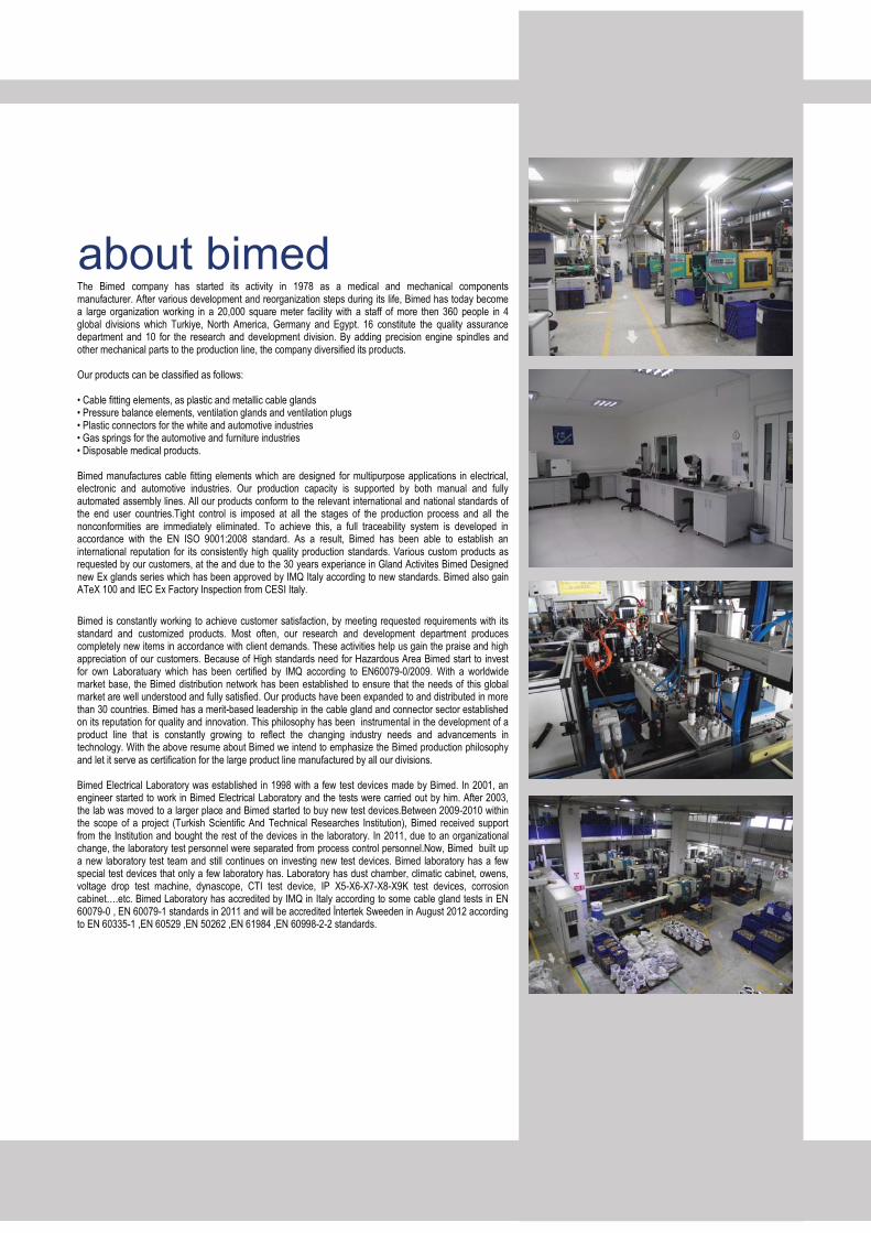
The Bimed company has started its activity in 1978 as a medical and mechanical components manufacturer. After various development and reorganization steps during its life, Bimed has today become a large organization working in a 20,000 square meter facility with a staff of more then 360 people in 4 global divisions which Turkiye, North America, Germany and Egypt. 16 constitute the quality assurance department and 10 for the research and development division. By adding precision engine spindles and other mechanical parts to the production line, the company diversified its products. Our products can be classified as follows: � Cable fitting elements, as plastic and metallic cable glands � Pressure balance elements, ventilation glands and ventilation plugs � Plastic connectors for the white and automotive industries � Gas springs for the automotive and furniture industries � Disposable medical products. Bimed manufactures cable fitting elements which are designed for multipurpose applications in electrical, electronic and automotive industries. Our production capacity is supported by both manual and fully automated assembly lines. All our products conform to the relevant international and national standards of the end user countries.Tight control is imposed at all the stages of the production process and all the nonconformities are immediately eliminated. To achieve this, a full traceability system is developed in accordance with the EN ISO 9001:2008 standard. As a result, Bimed has been able to establish an international reputation for its consistently high quality production standards. Various custom products as requested by our customers, at the and due to the 30 years experiance in Gland Activites Bimed Designed new Ex glands series which has been approved by IMQ Italy according to new standards. Bimed also gain ATeX 100 and IEC Ex Factory Inspection from CESI Italy.
Bimed is constantly working to achieve customer satisfaction, by meeting requested requirements with its standard and customized products. Most often, our research and development department produces completely new items in accordance with client demands. These activities help us gain the praise and high appreciation of our customers. Because of High standards need for Hazardous Area Bimed start to invest for own Laboratuary which has been certified by IMQ according to EN60079-0/2009. With a worldwide market base, the Bimed distribution network has been established to ensure that the needs of this global market are well understood and fully satisfied. Our products have been expanded to and distributed in more than 30 countries. Bimed has a merit-based leadership in the cable gland and connector sector established on its reputation for quality and innovation. This philosophy has been instrumental in the development of a product line that is constantly growing to reflect the changing industry needs and advancements in technology. With the above resume about Bimed we intend to emphasize the Bimed production philosophy and let it serve as certification for the large product line manufactured by all our divisions. Bimed Electrical Laboratory was established in 1998 with a few test devices made by Bimed. In 2001, an engineer started to work in Bimed Electrical Laboratory and the tests were carried out by him. After 2003, the lab was moved to a larger place and Bimed started to buy new test devices.Between 2009-2010 within the scope of a project (Turkish Scientific And Technical Researches Institution), Bimed received support from the Institution and bought the rest of the devices in the laboratory. In 2011, due to an organizational change, the laboratory test personnel were separated from process control personnel.Now, Bimed built up a new laboratory test team and still continues on investing new test devices. Bimed laboratory has a few special test devices that only a few laboratory has. Laboratory has dust chamber, climatic cabinet, owens, voltage drop test machine, dynascope, CTI test device, IP X5-X6-X7-X8-X9K test devices, corrosion cabinet….etc. Bimed Laboratory has accredited by IMQ in Italy according to some cable gland tests in EN 60079-0 , EN 60079-1 standards in 2011 and will be accredited �ntertek Sweeden in August 2012 according to EN 60335-1 ,EN 60529 ,EN 50262 ,EN 61984 ,EN 60998-2-2 standards.
about bimed
Plastic Cable Glands & Accessories
Metal Cable Glands & Accessories
Liquid Tight Conduit Fittings
Rigid Conduit Fittings
Pressure Balance Elements
Customer Oriented Products
Standard Series pg. 6 - 11
Conus Series pg. 12 - 13
Cable Protection Series pg. 14 - 18
Lock Nuts pg. 19 - 21
Blind Stops pg. 22 - 23
Dome Plugs pg. 24
Standard Series pg. 26 - 30
Double Seal Series
pg. 31
Big Size Cable Glands
pg. 32
EMC 2 Series pg. 34 - 38
EMC 3 Series pg. 39 - 40
EMC 4 Series pg. 41 - 44
Stainless Steel Gland
pg. 33
Lock Nuts pg. 45 - 47
Adaptors pg. 48 - 49
Quick Fitting Glands pg. 74
Elbow Glands pg. 75
Din Type Metric Glands pg. 76
RJ - 45 Glands pg. 77
NDL Cable Glands pg. 78
pg. 79
pg. 80
Neo Glands
Gland Wrench Tool
Straight Male Fittings pg. 51
45° Male Fittings pg. 52
90° Male Fittings pg. 53
Female Fittings pg. 54
Cable Hose Fittings pg. 55
Ferrules & Swivel Fittings pg. 59
Straight Fitting pg. 61
Enclosure Coupling pg. 62
Ventilation Plugs pg. 68 - 69
Ventilation Glands pg. 70 - 72
Flexible Conduit Set pg. 63
Straight Coupling pg. 64
Conduit Union pg. 65
Bend Coupling pg. 66
Straight Male Fittings SS
45° Male Fittings SS
90° Male Fittings SS
pg. 56
pg. 57
pg. 58
Indostrial Gland for Armored Cable
Hygienic Glands & Fittings
contents
5
60
50
25
67
73
90
Reducing Seals (Single) pg. 81
Reducing Seals (Double) pg. 82
pg. 83
pg. 84 - 85
Flat Cable SealsMultihole Seals
pg. 86
Hygienic Glands pg. 91-93
Hygienic Fittings pg. 94
Gaskets pg. 87
pg. 88Washers
Serrated Washers pg. 89
Certificates
95Push and Tighten GlandsPolyamide 6 and Brass, nickel plated glands pg. 96-97
Coil Spring GlandsStandard Brass and EMC Glands pg. 99-100
98
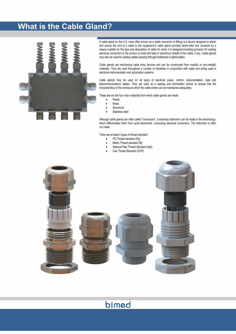
A cable gland (in the U.S. more often known as a cable connector or fitting) is a device designed to attach and secure the end of a cable to the equipment.A cable gland provides strain-relief and connects by a means suitable for the type and description of cable for which it is designed-including provision for making electrical connection to the armour or braid and lead or aluminium sheath of the cable, if any. Cable glands may also be used for sealing cables passing through bulkheads or gland plates. Cable glands are mechanical cable entry devices and can be constructed from metallic or non-metallic materials. They are used throughout a number of industries in conjunction with cable and wiring used in electrical instrumentation and automation systems. Cable glands may be used on all types of electrical power, control, instrumentation, data and telecommunications cables. They are used as a sealing and termination device to ensure that the characteristics of the enclosure which the cable enters can be maintained adequately. These are are the four main materials from which cable glands are made:
� Plastic � Brass � Aluminium � Stainless steel
Although cable glands are often called "connectors", a technical distinction can be made in the terminology, which differentiates them from quick-disconnect, conducting electrical connectors. The distinction is often not made. There are at least 4 types of thread standard
� PG Thread standard (Pg) � Metric Thread standard (M) � National Pipe Thread Standard (Npt) � Gas Thread Standard (G-Pf)
What is the Cable Gland?
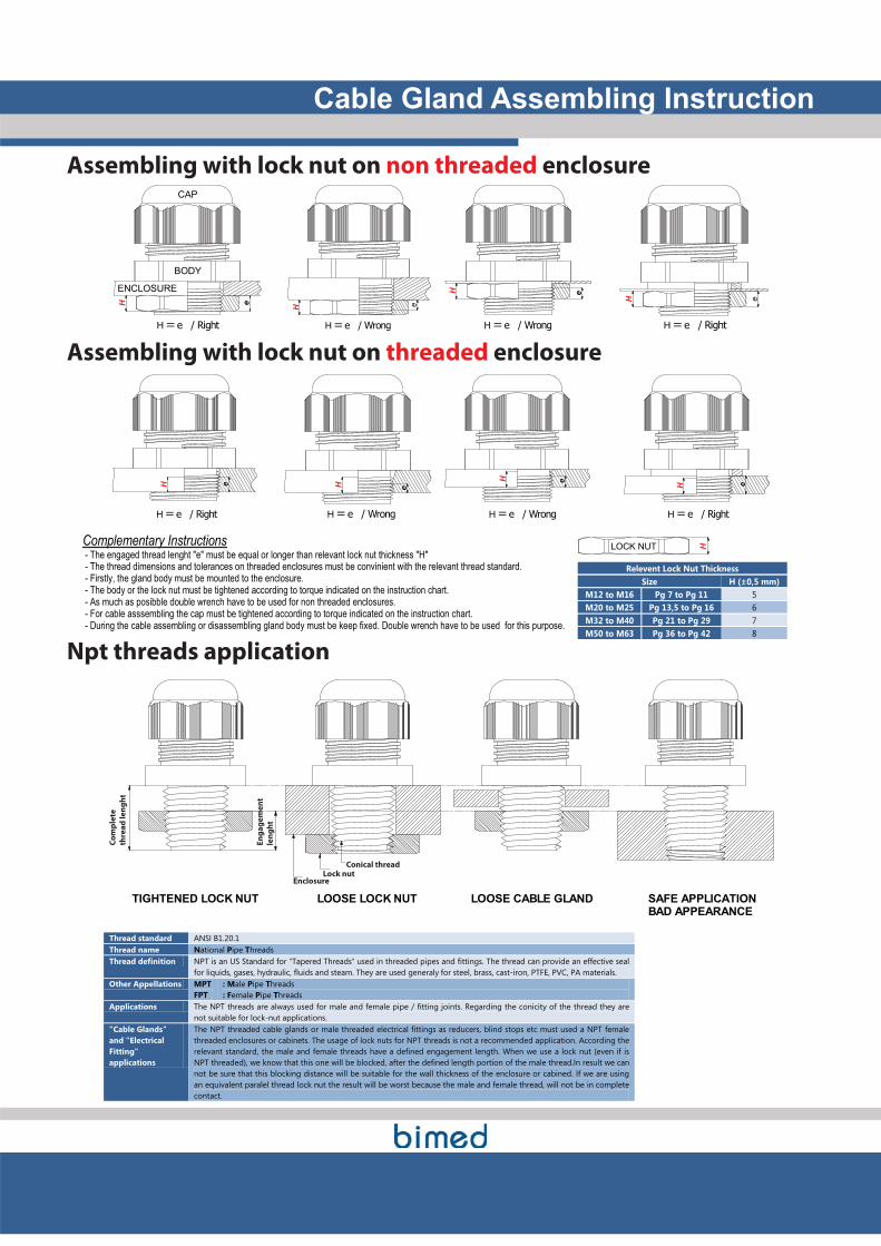
Cable Gland Assembling Instruction
Assembling with lock nut on non threaded enclosure
H =��e / Right
H e
CAP
BODY
ENCLOSURE
H =��e / Wrong
H e
H =��e / Wrong
H e
H =��e / Right
H e
Assembling with lock nut on threaded enclosure
H e
H =��e / Right
H e
H =��e / WrongH e
H =��e / Wrong
H e
H =��e / Right
Complementary Instructions - The engaged thread lenght "e" must be equal or longer than relevant lock nut thickness "H" - The thread dimensions and tolerances on threaded enclosures must be convinient with the relevant thread standard. - Firstly, the gland body must be mounted to the enclosure. - The body or the lock nut must be tightened according to torque indicated on the instruction chart. - As much as posibble double wrench have to be used for non threaded enclosures. - For cable asssembling the cap must be tightened according to torque indicated on the instruction chart. - During the cable assembling or disassembling gland body must be keep fixed. Double wrench have to be used for this purpose.
HLOCK NUT
Relevent Lock Nut Thickness Size H (±0,5 mm)
M12 to M16 Pg 7 to Pg 11 5 M20 to M25 Pg 13,5 to Pg 16 6 M32 to M40 Pg 21 to Pg 29 7 M50 to M63 Pg 36 to Pg 42 8
Npt threads application
Co
mp
lete
thre
ad
le
ng
ht
En
ga
ge
me
nt
len
gh
t
EnclosureLock nut
Conical thread
LOOSE LOCK NUT LOOSE CABLE GLANDTIGHTENED LOCK NUT SAFE APPLICATIONBAD APPEARANCE
Thread standard ANSI B1.20.1 Thread name National Pipe Threads Thread definition NPT is an US Standard for "Tapered Threads" used in threaded pipes and fittings. The thread can provide an effective seal
for liquids, gases, hydraulic, fluids and steam. They are used generaly for steel, brass, cast-iron, PTFE, PVC, PA materials. Other Appellations MPT
FPT : Male Pipe Threads : Female Pipe Threads
Applications The NPT threads are always used for male and female pipe / fitting joints. Regarding the conicity of the thread they are not suitable for lock-nut applications.
"Cable Glands" and "Electrical Fitting" applications
The NPT threaded cable glands or male threaded electrical fittings as reducers, blind stops etc must used a NPT female threaded enclosures or cabinets. The usage of lock nuts for NPT threads is not a recommended application. According the relevant standard, the male and female threads have a defined engagement length. When we use a lock nut (even if is NPT threaded), we know that this one will be blocked, after the defined length portion of the male thread.In result we can not be sure that this blocking distance will be suitable for the wall thickness of the enclosure or cabined. If we are using an equivalent paralel thread lock nut the result will be worst because the male and female thread, will not be in complete contact.
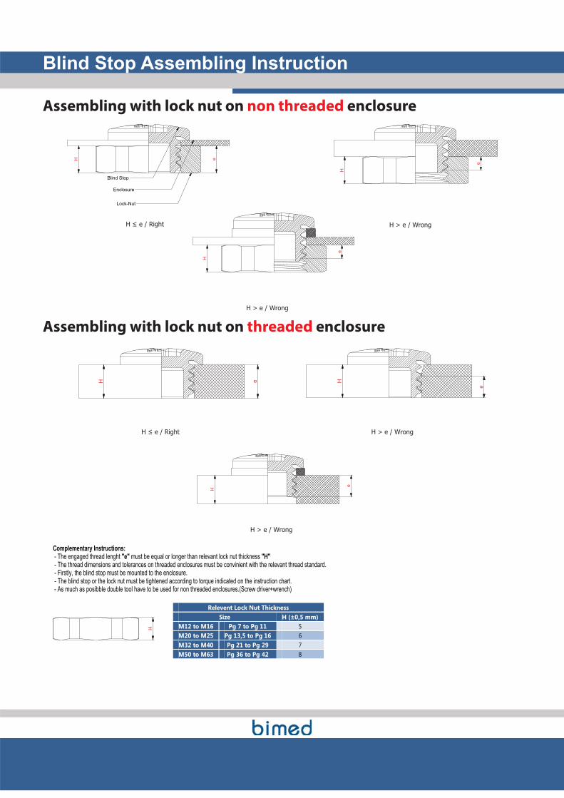
Blind Stop Assembling Instruction
Assembling with lock nut on non threaded enclosure
H e
�����������
Blind Stop
Enclosure
Lock-Nut
H
e
H > e / Wrong
H
e
H > e / Wrong
Assembling with lock nut on threaded enclosure
H e
�����������
H
e
H > e / Wrong
H
e
H > e / Wrong
Complementary Instructions: - The engaged thread lenght "e" must be equal or longer than relevant lock nut thickness "H" - The thread dimensions and tolerances on threaded enclosures must be convinient with the relevant thread standard. - Firstly, the blind stop must be mounted to the enclosure. - The blind stop or the lock nut must be tightened according to torque indicated on the instruction chart. - As much as posibble double tool have to be used for non threaded enclosures.(Screw driver+wrench)
H
Relevent Lock Nut Thickness Size H (±0,5 mm)
M12 to M16 Pg 7 to Pg 11 5 M20 to M25 Pg 13,5 to Pg 16 6 M32 to M40 Pg 21 to Pg 29 7 M50 to M63 Pg 36 to Pg 42 8
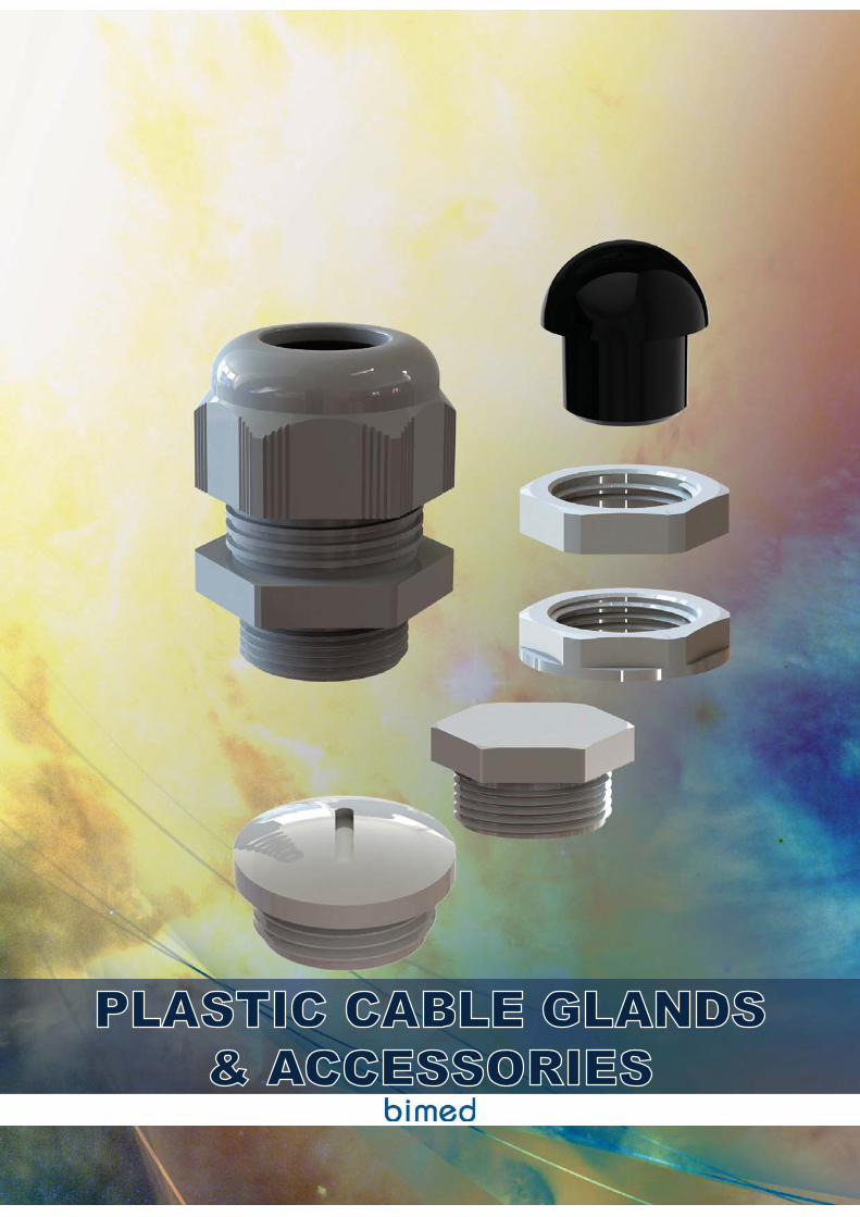
PLASTIC CABLE GLANDS& ACCESSORIES
STANDARD SERIESPLASTIC CABLE GLANDS
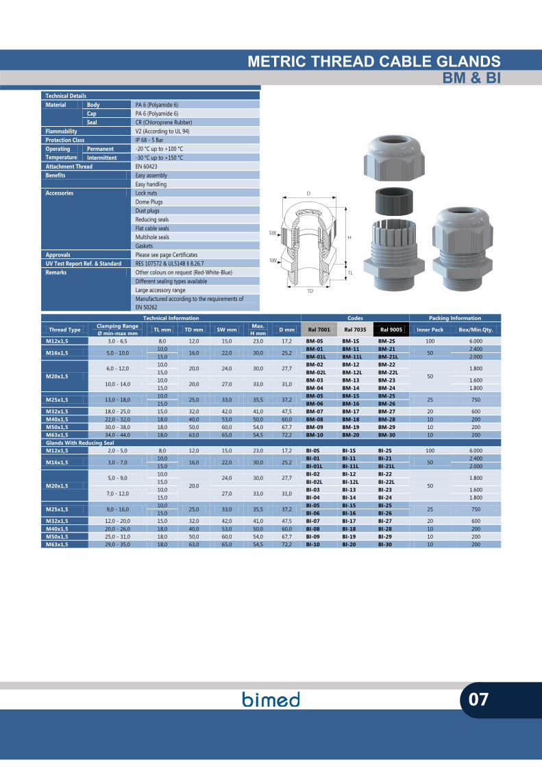
METRIC THREAD CABLE GLANDSBM & BI
07
TL
TD
SW
SW
D
H
Technical Details Material Body PA 6 (Polyamide 6)
Cap PA 6 (Polyamide 6) Seal CR (Chloroprene Rubber)
Flammability V2 (According to UL 94) Protection Class IP 68 - 5 Bar Operating Temperature
Permanent -20 °C up to +100 °C Intermittent -30 °C up to +150 °C
Attachment Thread EN 60423 Benefits Easy assembly
Easy handling Accessories Lock nuts
Dome Plugs Dust plugs Reducing seals Flat cable seals Multihole seals Gaskets
Approvals Please see page Certificates UV Test Report Ref. & Standard RES 107572 & UL514B § 8.26.7 Remarks Other colours on request (Red-White-Blue)
Different sealing types available Large accessory range Manufactured according to the requirements of EN 50262
Technical Information Codes Packing Information
Thread Type Clamping Range Ø min-max mm
TL mm TD mm SW mm Max.
H mm D mm Ral 7001 Ral 7035 Ral 9005 Inner Pack Box/Min.Qty.
M12x1,5 3,0 - 6,5 8,0 12,0 15,0 23,0 17,2 BM-0S BM-1S BM-2S 100 6.000
M16x1,5 5,0 - 10,0 10,0
16,0 22,0 30,0 25,2 BM-01 BM-11 BM-21
50 2.400
15,0 BM-01L BM-11L BM-21L 2.000
M20x1,5 6,0 - 12,0
10,0 20,0 24,0 30,0 27,7
BM-02 BM-12 BM-22
50 1.800
15,0 BM-02L BM-12L BM-22L
10,0 - 14,0 10,0
20,0 27,0 33,0 31,0 BM-03 BM-13 BM-23 1.600
15,0 BM-04 BM-14 BM-24 1.800
M25x1,5 13,0 - 18,0 10,0
25,0 33,0 35,5 37,2 BM-05 BM-15 BM-25
25 750 15,0 BM-06 BM-16 BM-26
M32x1,5 18,0 - 25,0 15,0 32,0 42,0 41,0 47,5 BM-07 BM-17 BM-27 20 600 M40x1,5 22,0 - 32,0 18,0 40,0 53,0 50,0 60,0 BM-08 BM-18 BM-28 10 200 M50x1,5 30,0 - 38,0 18,0 50,0 60,0 54,0 67,7 BM-09 BM-19 BM-29 10 200 M63x1,5 34,0 - 44,0 18,0 63,0 65,0 54,5 72,2 BM-10 BM-20 BM-30 10 200 Glands With Reducing Seal M12x1,5 2,0 - 5,0 8,0 12,0 15,0 23,0 17,2 BI-0S BI-1S BI-2S 100 6.000
M16x1,5 3,0 - 7,0 10,0
16,0 22,0 30,0 25,2 BI-01 BI-11 BI-21
50 2.400
15,0 BI-01L BI-11L BI-21L 2.000
M20x1,5 5,0 - 9,0
10,0
20,0 24,0 30,0 27,7
BI-02 BI-12 BI-22
50 1.800
15,0 BI-02L BI-12L BI-22L
7,0 - 12,0 10,0
27,0 33,0 31,0 BI-03 BI-13 BI-23 1.600
15,0 BI-04 BI-14 BI-24 1.800
M25x1,5 9,0 - 16,0 10,0
25,0 33,0 35,5 37,2 BI-05 BI-15 BI-25
25 750 15,0 BI-06 BI-16 BI-26
M32x1,5 12,0 - 20,0 15,0 32,0 42,0 41,0 47,5 BI-07 BI-17 BI-27 20 600 M40x1,5 20,0 - 26,0 18,0 40,0 53,0 50,0 60,0 BI-08 BI-18 BI-28 10 200 M50x1,5 25,0 - 31,0 18,0 50,0 60,0 54,0 67,7 BI-09 BI-19 BI-29 10 200 M63x1,5 29,0 - 35,0 18,0 63,0 65,0 54,5 72,2 BI-10 BI-20 BI-30 10 200
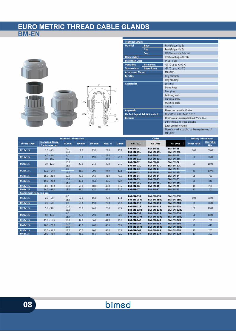
EURO METRIC THREAD CABLE GLANDSBM-EN
08
Technical Details Material Body PA 6 (Polyamide 6)
Cap PA 6 (Polyamide 6) Seal CR (Chloroprene Rubber)
Flammability V2 (According to UL 94) Protection Class IP 68 - 5 Bar Operating Temperature
Permanent -20 °C up to +100 °C Intermittent -30 °C up to +150°C
Attachment Thread EN 60423 Benefits Easy assembly
Easy handling Accessories Lock nuts
Dome Plugs Dust plugs Reducing seals Flat cable seals Multihole seals Gaskets
Approvals Please see page Certificates UV Test Report Ref. & Standard RES 107572 & UL514B § 8.26.7 Remarks Other colours on request (Red-White-Blue)
Different sealing types available Large accessory range Manufactured according to the requirements of EN 50262
TL
TD
SW
SW
D
H
Technical Information Codes Packing Information
Thread Type Clamping Range Ø min-max mm
TL mm TD mm SW mm Max. H D mm Ral 7001 Ral 7035 Ral 9005 Inner Pack Box/Min.
Qty.
M12x1,5 3,0 - 6,5 8,0
12,0 15,0 22,0 17,1 BM-EN-0S BM-EN-1S BM-EN-2S
100 6000 15,0 BM-EN-0SL BM-EN-1SL BM-EN-2SL
M16x1,5 4,0 - 8,0 8,0
16,0 19,0 25,0
21,6 BM-EN-01 BM-EN-11 BM-EN-21
50 3000 5,0 - 10,0 9,0 27,0 BM-EN-01S BM-EN-11S BM-EN-21S
M20x1,5 6,0 - 12,0 10,0
20,0 24,0 29,0 27,7 BM-EN-02 BM-EN-12 BM-EN-22
50 1800 15,0 BM-EN-02L BM-EN-12L BM-EN-22L
M25x1,5 11,0 - 17,0 8,0
25,0 29,0 34,0 32,5 BM-EN-03 BM-EN-13 BM-EN-23
50 1000 15,0 BM-EN-03L BM-EN-13L BM-EN-23L
M32x1,5 15,0 - 21,0 10,0 32,0 36,0 41,0 41,0 BM-EN-04 BM-EN-14 BM-EN-24 25 750
M40x1,5 19,0 - 28,0 10,0
40,0 46,0 45,5 52,4 BM-EN-05 BM-EN-15 BM-EN-25
20 440 18,0 BM-EN-05L BM-EN-15L BM-EN-25L
M50x1,5 30,0 - 38,0 18,0 50,0 60,0 49,0 67,7 BM-EN-06 BM-EN-16 BM-EN-26 10 200 M63x1,5 34,0 - 44,0 18,0 63,0 65,0 49,0 72,2 BM-EN-07 BM-EN-17 BM-EN-27 10 200 Glands with Reducing Seal
M12x1,5 2,0 - 5,0 8,0
12,0 15,0 22,0 17,1 BM-EN-0SR BM-EN-1SR BM-EN-2SR
100 6000 15,0 BM-EN-0SRL BM-EN-1SRL BM-EN-2SRL
M16x1,5 2,0 - 6,0 8,0 16,0 19,0 25,0 21,6 BM-EN-01R BM-EN-11R BM-EN-21R 50 3000
M20x1,5 5,0 - 9,0 10,0
20,0 24,0 29,0 27,7 BM-EN-02R BM-EN-12R BM-EN-22R
50 1800 15,0 BM-EN-02RL BM-EN-12RL BM-EN-22RL
M25x1,5 9,0 - 13,0 8,0
25,0 29,0 34,0 32,5 BM-EN-03R BM-EN-13R BM-EN-23R
50 1000 15,0 BM-EN-03RL BM-EN-13RL BM-EN-23RL
M32x1,5 11,0 - 15,5 10,0 32,0 36,0 41,0 41,0 BM-EN-04R BM-EN-14R BM-EN-24R 25 750
M40x1,5 16,0 - 23,0 10,0
40,0 46,0 45,5 52,4 BM-EN-05R BM-EN-15R BM-EN-25R
20 440 18,0 BM-EN-05RL BM-EN-15RL BM-EN-25RL
M50x1,5 25,0 - 31,0 18,0 50,0 60,0 49,0 67,7 BM-EN-06R BM-EN-16R BM-EN-26R 10 200 M63x1,5 29,0 - 35,0 18,0 63,0 65,0 49,0 72,2 BM-EN-07R BM-EN-17R BM-EN-27R 10 200
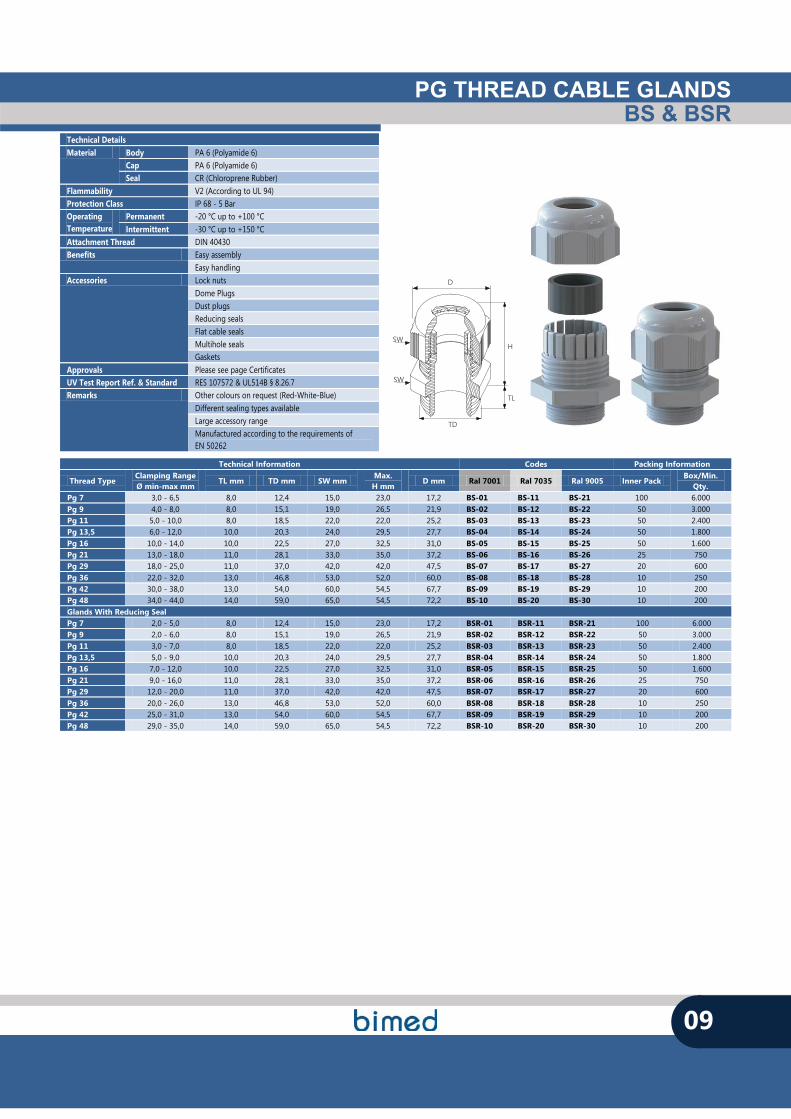
Technical Details Material Body PA 6 (Polyamide 6)
Cap PA 6 (Polyamide 6) Seal CR (Chloroprene Rubber)
Flammability V2 (According to UL 94) Protection Class IP 68 - 5 Bar Operating Temperature
Permanent -20 °C up to +100 °C Intermittent -30 °C up to +150 °C
Attachment Thread DIN 40430 Benefits Easy assembly
Easy handling Accessories Lock nuts
Dome Plugs Dust plugs Reducing seals Flat cable seals Multihole seals Gaskets
Approvals Please see page Certificates UV Test Report Ref. & Standard RES 107572 & UL514B § 8.26.7 Remarks Other colours on request (Red-White-Blue)
Different sealing types available Large accessory range Manufactured according to the requirements of EN 50262
PG THREAD CABLE GLANDSBS & BSR
09
TL
TD
SW
SW
D
H
Technical Information Codes Packing Information
Thread Type Clamping Range Ø min-max mm
TL mm TD mm SW mm Max.
H mm D mm Ral 7001 Ral 7035 Ral 9005 Inner Pack
Box/Min. Qty.
Pg 7 3,0 - 6,5 8,0 12,4 15,0 23,0 17,2 BS-01 BS-11 BS-21 100 6.000 Pg 9 4,0 - 8,0 8,0 15,1 19,0 26,5 21,9 BS-02 BS-12 BS-22 50 3.000 Pg 11 5,0 - 10,0 8,0 18,5 22,0 22,0 25,2 BS-03 BS-13 BS-23 50 2.400 Pg 13,5 6,0 - 12,0 10,0 20,3 24,0 29,5 27,7 BS-04 BS-14 BS-24 50 1.800 Pg 16 10,0 - 14,0 10,0 22,5 27,0 32,5 31,0 BS-05 BS-15 BS-25 50 1.600 Pg 21 13,0 - 18,0 11,0 28,1 33,0 35,0 37,2 BS-06 BS-16 BS-26 25 750 Pg 29 18,0 - 25,0 11,0 37,0 42,0 42,0 47,5 BS-07 BS-17 BS-27 20 600 Pg 36 22,0 - 32,0 13,0 46,8 53,0 52,0 60,0 BS-08 BS-18 BS-28 10 250 Pg 42 30,0 - 38,0 13,0 54,0 60,0 54,5 67,7 BS-09 BS-19 BS-29 10 200 Pg 48 34,0 - 44,0 14,0 59,0 65,0 54,5 72,2 BS-10 BS-20 BS-30 10 200 Glands With Reducing Seal Pg 7 2,0 - 5,0 8,0 12,4 15,0 23,0 17,2 BSR-01 BSR-11 BSR-21 100 6.000 Pg 9 2,0 - 6,0 8,0 15,1 19,0 26,5 21,9 BSR-02 BSR-12 BSR-22 50 3.000 Pg 11 3,0 - 7,0 8,0 18,5 22,0 22,0 25,2 BSR-03 BSR-13 BSR-23 50 2.400 Pg 13,5 5,0 - 9,0 10,0 20,3 24,0 29,5 27,7 BSR-04 BSR-14 BSR-24 50 1.800 Pg 16 7,0 - 12,0 10,0 22,5 27,0 32,5 31,0 BSR-05 BSR-15 BSR-25 50 1.600 Pg 21 9,0 - 16,0 11,0 28,1 33,0 35,0 37,2 BSR-06 BSR-16 BSR-26 25 750 Pg 29 12,0 - 20,0 11,0 37,0 42,0 42,0 47,5 BSR-07 BSR-17 BSR-27 20 600 Pg 36 20,0 - 26,0 13,0 46,8 53,0 52,0 60,0 BSR-08 BSR-18 BSR-28 10 250 Pg 42 25,0 - 31,0 13,0 54,0 60,0 54,5 67,7 BSR-09 BSR-19 BSR-29 10 200 Pg 48 29,0 - 35,0 14,0 59,0 65,0 54,5 72,2 BSR-10 BSR-20 BSR-30 10 200
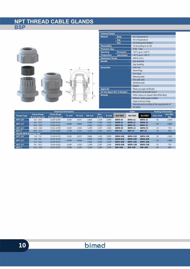
NPT THREAD CABLE GLANDSBSP
10
TL
TD
SW
SW
D
H
Technical Details Material Body PA 6 (Polyamide 6)
Cap PA 6 (Polyamide 6) Seal CR (Chloroprene Rubber)
Flammability V2 (According to UL 94) Protection Class IP 68 - 5 Bar Operating Temperature
Permanent -20 °C up to +100 °C Intermittent -30 °C up to +150 °C
Attachment Thread ANSI B 1.20.1 Benefits Easy assembly
Easy handling Accessories Lock nuts
Dome Plugs Dust plugs Reducing seals Flat cable seals Multihole seals Gaskets
Approvals Please see page Certificates UV Test Report Ref. & Standard RES 107572 & UL514B § 8.26.7 Remarks Other colours on request (Red-White-Blue)
Different sealing types available Large accessory range Manufactured according to the requirements of EN 50262
Technical Information Codes Packing Information
Thread Type Clamp.Range
Ø min-max mm Clamp.Range
Ø min-max inch TL inch TD inch SW inch
Max. H inch
D inch Ral 7001 Ral 7035 Ral 9005 Inner Pack Box/Min.
Qty. NPT 3/8" 5,0 - 10,0 0,197-0,394 0,590 0,675 0,866 1,140 0,990 BSPA-01 BSPA-11 BSPA-21 50 2.000
NPT 1/2" 6,0 - 12,0 0,236-0,472
0,590 0,840 0,940 1,200 1,090 BSPB-02 BSPB-12 BSPB-22
50 1.800 10,0 - 14,0 0,394-0,551 1,062 1,263 1,220 BSPC-02 BSPC-12 BSPC-22
NPT 3/4" 13,0 - 18,0 0,511-0,709 0,590 1,050 1,299 1,397 1,464 BSPD-03 BSPD-13 BSPD-23 25 750 NPT 1" 18,0 - 25,0 0,709-0,984 0,708 1,315 1,650 1,594 1,870 BSP-04 BSP-14 BSP-24 20 600 Glands With Reducing Seal NPT 3/8" 3,0 - 7,0 0,118-0,276 0,590 0,675 0,866 1,140 0,990 BSPA-01R BSPA-11R BSPA-21R 50 2.000
NPT 1/2" 5,0 - 9,0 0,197-0,354
0,590 0,840 0,940 1,200 1,090 BSPB-02R BSPB-12R BSPB-22R
50 1.800 7,0 - 12,0 0,276-0,472 1,062 1,263 1,220 BSPC-02R BSPC-12R BSPC-22R
NPT 3/4" 9,0 - 16,0 0,354-0,630 0,590 1,050 1,299 1,397 1,464 BSPD-03R BSPD-13R BSPD-23R 25 750 NPT 1" 12,0 - 20,0 0,472-0,787 0,708 1,315 1,650 1,594 1,870 BSP-04R BSP-14R BSP-24R 20 600
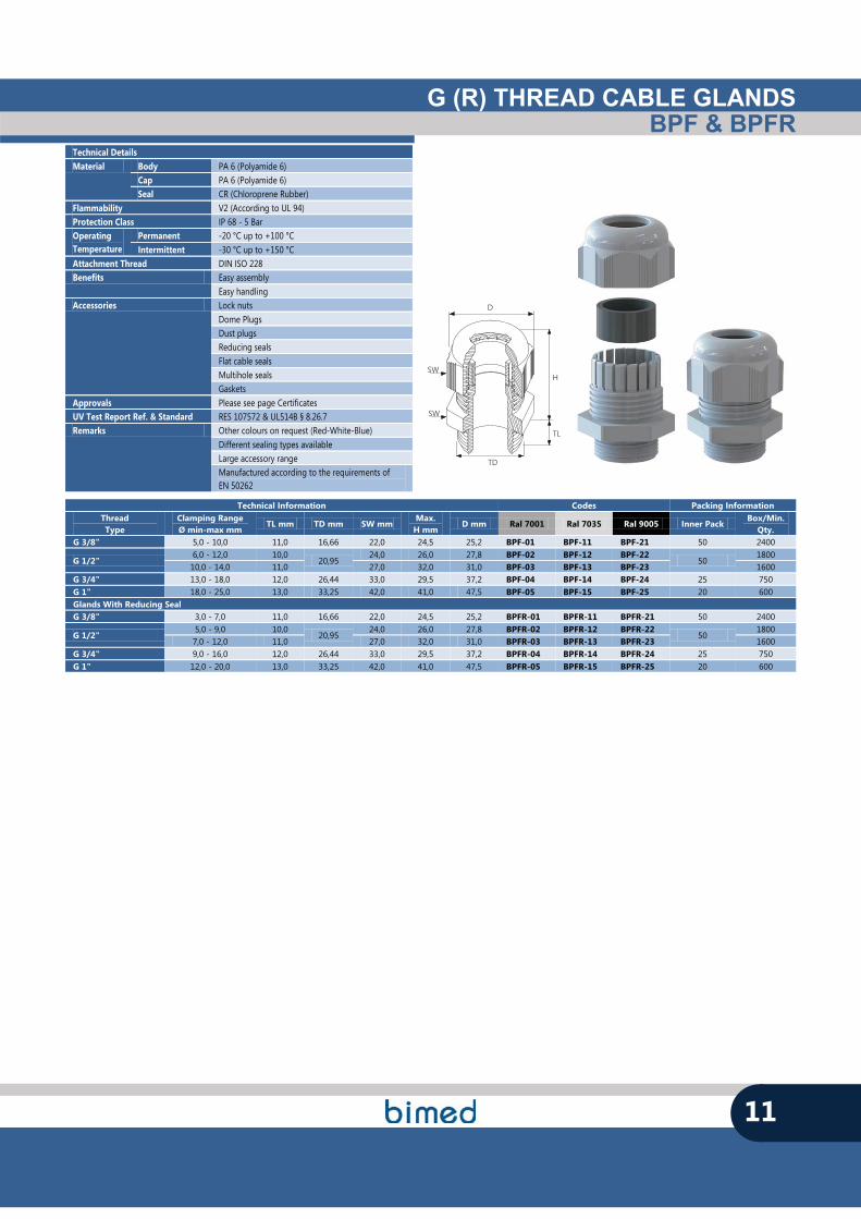
G (R) THREAD CABLE GLANDSBPF & BPFR
11
TL
TD
SW
SW
D
H
Technical Details Material Body PA 6 (Polyamide 6)
Cap PA 6 (Polyamide 6) Seal CR (Chloroprene Rubber)
Flammability V2 (According to UL 94) Protection Class IP 68 - 5 Bar Operating Temperature
Permanent -20 °C up to +100 °C Intermittent -30 °C up to +150 °C
Attachment Thread DIN ISO 228 Benefits Easy assembly
Easy handling Accessories Lock nuts
Dome Plugs Dust plugs Reducing seals Flat cable seals Multihole seals Gaskets
Approvals Please see page Certificates UV Test Report Ref. & Standard RES 107572 & UL514B § 8.26.7 Remarks Other colours on request (Red-White-Blue)
Different sealing types available Large accessory range Manufactured according to the requirements of EN 50262
Technical Information Codes Packing Information Thread Type
Clamping Range Ø min-max mm
TL mm TD mm SW mm Max.
H mm D mm Ral 7001 Ral 7035 Ral 9005 Inner Pack
Box/Min. Qty.
G 3/8" 5,0 - 10,0 11,0 16,66 22,0 24,5 25,2 BPF-01 BPF-11 BPF-21 50 2400
G 1/2" 6,0 - 12,0 10,0
20,95 24,0 26,0 27,8 BPF-02 BPF-12 BPF-22
50 1800
10,0 - 14,0 11,0 27,0 32,0 31,0 BPF-03 BPF-13 BPF-23 1600 G 3/4" 13,0 - 18,0 12,0 26,44 33,0 29,5 37,2 BPF-04 BPF-14 BPF-24 25 750 G 1" 18,0 - 25,0 13,0 33,25 42,0 41,0 47,5 BPF-05 BPF-15 BPF-25 20 600 Glands With Reducing Seal G 3/8" 3,0 - 7,0 11,0 16,66 22,0 24,5 25,2 BPFR-01 BPFR-11 BPFR-21 50 2400
G 1/2" 5,0 - 9,0 10,0
20,95 24,0 26,0 27,8 BPFR-02 BPFR-12 BPFR-22
50 1800
7,0 - 12,0 11,0 27,0 32,0 31,0 BPFR-03 BPFR-13 BPFR-23 1600 G 3/4" 9,0 - 16,0 12,0 26,44 33,0 29,5 37,2 BPFR-04 BPFR-14 BPFR-24 25 750 G 1" 12,0 - 20,0 13,0 33,25 42,0 41,0 47,5 BPFR-05 BPFR-15 BPFR-25 20 600

CONUS SERIESPLASTIC CABLE GLANDS
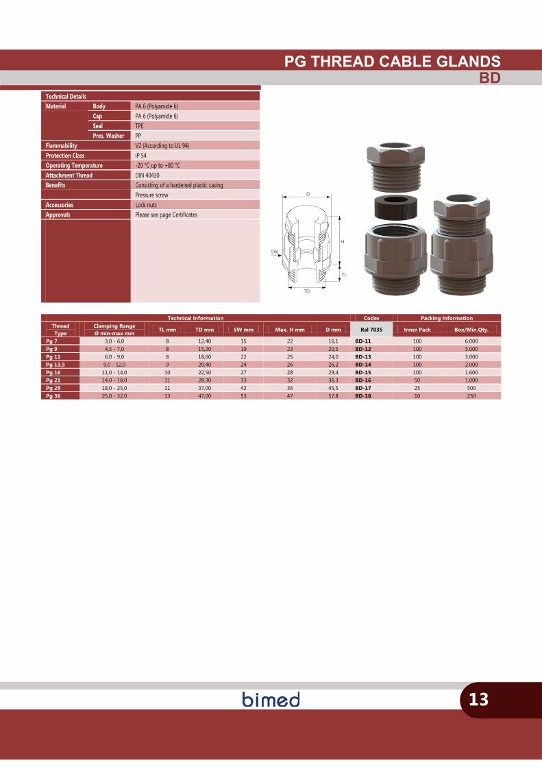
PG THREAD CABLE GLANDSBD
13
TL
TD
SW
D
H
Technical Information Codes Packing Information Thread Type
Clamping Range Ø min-max mm
TL mm TD mm SW mm Max. H mm D mm Ral 7035 Inner Pack Box/Min.Qty.
Pg 7 3,0 - 6,0 8 12,40 15 22 16,1 BD-11 100 6.000 Pg 9 4,5 - 7,0 8 15,20 19 23 20,5 BD-12 100 5.000 Pg 11 6,0 - 9,0 8 18,60 22 25 24,0 BD-13 100 3.000 Pg 13,5 9,0 - 12,0 9 20,40 24 26 26,2 BD-14 100 2.000 Pg 16 11,0 - 14,0 10 22,50 27 28 29,4 BD-15 100 1.600 Pg 21 14,0 - 18,0 11 28,30 33 32 36,3 BD-16 50 1.000 Pg 29 18,0 - 25,0 11 37,00 42 36 45,5 BD-17 25 500 Pg 36 25,0 - 32,0 13 47,00 53 47 57,8 BD-18 10 250
Technical Details Material Body PA 6 (Polyamide 6)
Cap PA 6 (Polyamide 6) Seal TPE Pres. Washer PP
Flammability V2 (According to UL 94) Protection Class IP 54 Operating Temperature -20 °C up to +80 °C Attachment Thread DIN 40430 Benefits Consisting of a hardened plastic casing
Pressure screw Accessories Lock nuts Approvals Please see page Certificates
CABLE PROTECTION SERIESPLASTIC CABLE GLANDS
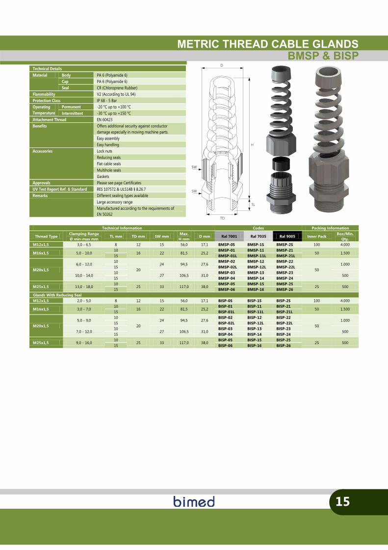
METRIC THREAD CABLE GLANDSBMSP & BISP
Technical Information Codes Packing Information
Thread Type Clamping Range Ø min-max mm
TL mm TD mm SW mm Max.
H mm D mm Ral 7001 Ral 7035 Ral 9005 Inner Pack
Box/Min. Qty.
M12x1,5 3,0 - 6,5 8 12 15 56,0 17,1 BMSP-0S BMSP-1S BMSP-2S 100 4.000
M16x1,5 5,0 - 10,0 10
16 22 81,5 25,2 BMSP-01 BMSP-11 BMSP-21
50 1.500 15 BMSP-01L BMSP-11L BMSP-21L
M20x1,5 6,0 - 12,0
10
20 24 94,5 27,6
BMSP-02 BMSP-12 BMSP-22
50 1.000
15 BMSP-02L BMSP-12L BMSP-22L
10,0 - 14,0 10
27 106,5 31,0 BMSP-03 BMSP-13 BMSP-23
500 15 BMSP-04 BMSP-14 BMSP-24
M25x1,5 13,0 - 18,0 10
25 33 117,0 38,0 BMSP-05 BMSP-15 BMSP-25
25 500 15 BMSP-06 BMSP-16 BMSP-26
Glands With Reducing Seal M12x1,5 2,0 - 5,0 8 12 15 56,0 17,1 BISP-0S BISP-1S BISP-2S 100 4.000
M16x1,5 3,0 - 7,0 10
16 22 81,5 25,2 BISP-01 BISP-11 BISP-21
50 1.500 15 BISP-01L BISP-11L BISP-21L
M20x1,5 5,0 - 9,0
10
20 24 94,5 27,6
BISP-02 BISP-12 BISP-22
50 1.000
15 BISP-02L BISP-12L BISP-22L
7,0 - 12,0 10
27 106,5 31,0 BISP-03 BISP-13 BISP-23
500 15 BISP-04 BISP-14 BISP-24
M25x1,5 9,0 - 16,0 10
25 33 117,0 38,0 BISP-05 BISP-15 BISP-25
25 500 15 BISP-06 BISP-16 BISP-26
15
TL
TD
SW
D
H
SW
Technical Details Material Body PA 6 (Polyamide 6)
Cap PA 6 (Polyamide 6) Seal CR (Chloroprene Rubber)
Flammability V2 (According to UL 94) Protection Class IP 68 - 5 Bar Operating Temperature
Permanent -20 °C up to +100 °C Intermittent -30 °C up to +150 °C
Attachment Thread EN 60423 Benefits Offers additional security against conductor
damage especially in moving machine parts. Easy assembly Easy handling
Accessories Lock nuts Reducing seals Flat cable seals Multihole seals Gaskets
Approvals Please see page Certificates UV Test Report Ref. & Standard RES 107572 & UL514B § 8.26.7 Remarks Different sealing types available
Large accessory range Manufactured according to the requirements of EN 50262
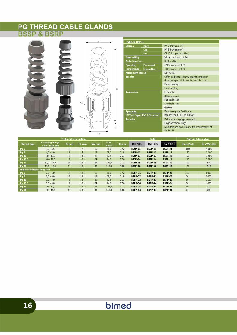
PG THREAD CABLE GLANDSBSSP & BSRP
16
TL
TD
SW
D
H
SW
S
S
Technical Information Codes Packing Information
Thread Type Clamping Range Ø min-max mm
TL mm TD mm SW mm Max.
H mm D mm Ral 7001 Ral 7035 Ral 9005 Inner Pack Box/Min.Qty.
Pg 7 3,0 - 6,5 8 12,4 15 56,0 17,2 BSSP-01 BSSP-11 BSSP-21 100 4.000 Pg 9 4,0 - 8,0 8 15,1 19 69,0 21,8 BSSP-02 BSSP-12 BSSP-22 50 2.000 Pg 11 5,0 - 10,0 8 18,5 22 82,5 25,3 BSSP-03 BSSP-13 BSSP-23 50 1.500 Pg 13,5 6,0 - 12,0 9 20,3 24 94,0 27,6 BSSP-04 BSSP-14 BSSP-24 50 1.000 Pg 16 10,0 - 14,0 10 22,5 27 106,0 31,1 BSSP-05 BSSP-15 BSSP-25 50 500 Pg 21 13,0 - 18,0 11 28,1 33 117,0 38,0 BSSP-06 BSSP-16 BSSP-26 25 500 Glands With Reducing Seal Pg 7 2,0 - 5,0 8 12,4 15 56,0 17,2 BSRP-01 BSRP-11 BSRP-21 100 4.000 Pg 9 2,0 - 6,0 8 15,1 19 69,0 21,8 BSRP-02 BSRP-12 BSRP-22 50 2.000 Pg 11 3,0 - 7,0 8 18,5 22 82,5 25,3 BSRP-03 BSRP-13 BSRP-23 50 1.500 Pg 13,5 5,0 - 9,0 9 20,3 24 94,0 27,6 BSRP-04 BSRP-14 BSRP-24 50 1.000 Pg 16 7,0 - 12,0 10 22,5 27 106,0 31,1 BSRP-05 BSRP-15 BSRP-25 50 500 Pg 21 9,0 - 16,0 11 28,1 33 117,0 38,0 BSRP-06 BSRP-16 BSRP-26 25 500
Technical Details Material Body PA 6 (Polyamide 6)
Cap PA 6 (Polyamide 6) Seal CR (Chloroprene Rubber)
Flammability V2 (According to UL 94) Protection Class IP 68 - 5 Bar Operating Temperature
Permanent -20 °C up to +100 °C Intermittent -30 °C up to +150 °C
Attachment Thread DIN 40430 Benefits Offers additional security against conductor
damage especially in moving machine parts. Easy assemblyEasy handling
Accessories Lock nuts Reducing seals Flat cable seals Multihole seals Gaskets
Approvals Please see page Certificates UV Test Report Ref. & Standard RES 107572 & UL514B § 8.26.7 Remarks Different sealing types available
Large accessory range Manufactured according to the requirements of EN 50262
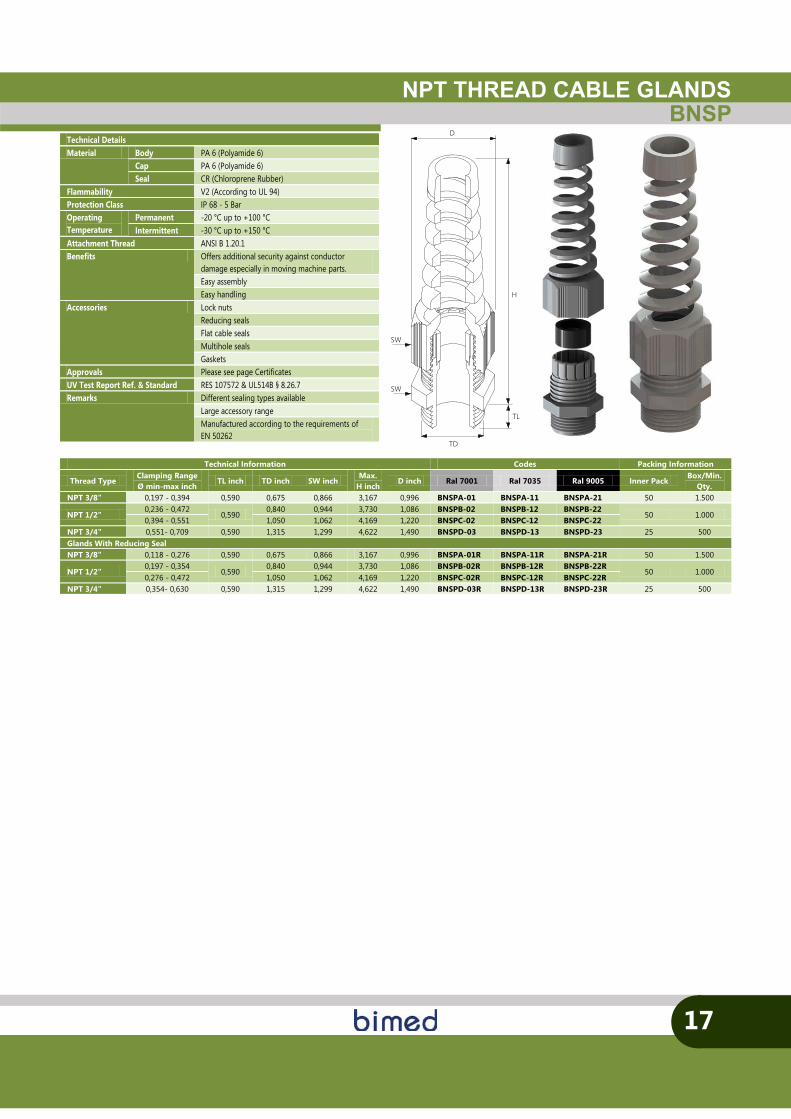
NPT THREAD CABLE GLANDSBNSP
17
TL
TD
SW
D
H
SW
Technical Information Codes Packing Information
Thread Type Clamping Range Ø min-max inch
TL inch TD inch SW inch Max.
H inch D inch Ral 7001 Ral 7035 Ral 9005 Inner Pack
Box/Min. Qty.
NPT 3/8" 0,197 - 0,394 0,590 0,675 0,866 3,167 0,996 BNSPA-01 BNSPA-11 BNSPA-21 50 1.500
NPT 1/2" 0,236 - 0,472
0,590 0,840 0,944 3,730 1,086 BNSPB-02 BNSPB-12 BNSPB-22
50 1.000 0,394 - 0,551 1,050 1,062 4,169 1,220 BNSPC-02 BNSPC-12 BNSPC-22
NPT 3/4" 0,551- 0,709 0,590 1,315 1,299 4,622 1,490 BNSPD-03 BNSPD-13 BNSPD-23 25 500 Glands With Reducing Seal NPT 3/8" 0,118 - 0,276 0,590 0,675 0,866 3,167 0,996 BNSPA-01R BNSPA-11R BNSPA-21R 50 1.500
NPT 1/2" 0,197 - 0,354
0,590 0,840 0,944 3,730 1,086 BNSPB-02R BNSPB-12R BNSPB-22R
50 1.000 0,276 - 0,472 1,050 1,062 4,169 1,220 BNSPC-02R BNSPC-12R BNSPC-22R
NPT 3/4" 0,354- 0,630 0,590 1,315 1,299 4,622 1,490 BNSPD-03R BNSPD-13R BNSPD-23R 25 500
Technical Details Material Body PA 6 (Polyamide 6)
Cap PA 6 (Polyamide 6) Seal CR (Chloroprene Rubber)
Flammability V2 (According to UL 94) Protection Class IP 68 - 5 Bar Operating Temperature
Permanent -20 °C up to +100 °C Intermittent -30 °C up to +150 °C
Attachment Thread ANSI B 1.20.1 Benefits Offers additional security against conductor
damage especially in moving machine parts. Easy assembly Easy handling
Accessories Lock nuts Reducing seals Flat cable seals Multihole seals Gaskets
Approvals Please see page Certificates UV Test Report Ref. & Standard RES 107572 & UL514B § 8.26.7 Remarks Different sealing types available
Large accessory range Manufactured according to the requirements of EN 50262
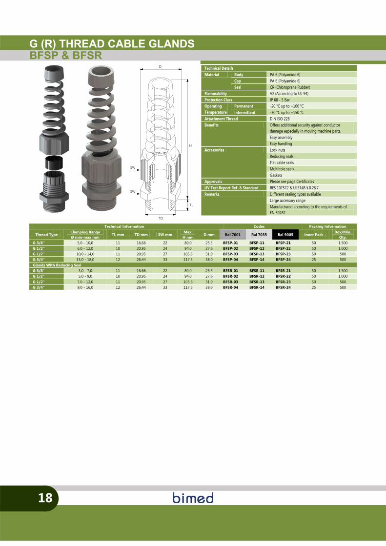
G (R) THREAD CABLE GLANDSBFSP & BFSR
18
TL
TD
SW
D
H
SW
Technical Information Codes Packing Information
Thread Type Clamping Range Ø min-max mm
TL mm TD mm SW mm Max.
H mm D mm Ral 7001 Ral 7035 Ral 9005 Inner Pack
Box/Min. Qty.
G 3/8" 5,0 - 10,0 11 16,66 22 80,0 25,3 BFSP-01 BFSP-11 BFSP-21 50 1.500 G 1/2" 6,0 - 12,0 10 20,95 24 94,0 27,6 BFSP-02 BFSP-12 BFSP-22 50 1.000 G 1/2" 10,0 - 14,0 11 20,95 27 105,6 31,0 BFSP-03 BFSP-13 BFSP-23 50 500 G 3/4" 13,0 - 18,0 12 26,44 33 117,5 38,0 BFSP-04 BFSP-14 BFSP-24 25 500 Glands With Reducing Seal G 3/8" 3,0 - 7,0 11 16,66 22 80,0 25,3 BFSR-01 BFSR-11 BFSR-21 50 1.500 G 1/2" 5,0 - 9,0 10 20,95 24 94,0 27,6 BFSR-02 BFSR-12 BFSR-22 50 1.000 G 1/2" 7,0 - 12,0 11 20,95 27 105,6 31,0 BFSR-03 BFSR-13 BFSR-23 50 500 G 3/4" 9,0 - 16,0 12 26,44 33 117,5 38,0 BFSR-04 BFSR-14 BFSR-24 25 500
Technical Details Material Body PA 6 (Polyamide 6)
Cap PA 6 (Polyamide 6) Seal CR (Chloroprene Rubber)
Flammability V2 (According to UL 94) Protection Class IP 68 - 5 Bar Operating Temperature
Permanent -20 °C up to +100 °C Intermittent -30 °C up to +150 °C
Attachment Thread DIN ISO 228 Benefits Offers additional security against conductor
damage especially in moving machine parts. Easy assembly Easy handling
Accessories Lock nuts Reducing seals Flat cable seals Multihole seals Gaskets
Approvals Please see page Certificates UV Test Report Ref. & Standard RES 107572 & UL514B § 8.26.7 Remarks Different sealing types available
Large accessory range Manufactured according to the requirements of EN 50262
PLASTICACCESSORIES
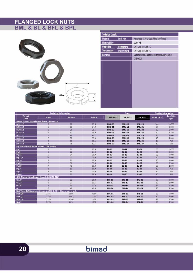
FLANGED LOCK NUTSBML & BL & BFL & BPL
D
H
SW
Technical Information Codes Packing Information Thread Type
H mm SW mm D mm Ral 7001 Ral 7035 Ral 9005 Inner Pack Box/Min.
Qty. Metric Thread (Attachment thread : EN 60423) M12x1,5 5 18 19,5 BML-0S BML-1S BML-2S 100 10.000 M16x1,5 5 22 24,2 BML-01 BML-11 BML-21 50 7.000 M20x1,5 6 26 28,6 BML-02 BML-12 BML-22 50 5.000 M25x1,5 6 32 35,0 BML-03 BML-13 BML-23 50 3.750 M32x1,5 7 41 46,1 BML-04 BML-14 BML-24 25 2.000 M40x1,5 7 50 55,3 BML-05 BML-15 BML-25 10 1.000 M50x1,5 8 60 66,1 BML-06 BML-16 BML-26 10 750 M63x1,5 8 75 82,5 BML-07 BML-17 BML-27 10 500 Pg Thread (Attachment thread : DIN 40430) Pg 7 5 19 21,0 BL-01 BL-11 BL-21 50 10.000 Pg 9 5 22 24,0 BL-02 BL-12 BL-22 50 9.000 Pg 11 5 24 26,0 BL-03 BL-13 BL-23 50 7.000 Pg 13,5 6 27 29,0 BL-04 BL-14 BL-24 50 5.000 Pg 16 6 30 33,0 BL-05 BL-15 BL-25 50 4.000 Pg 21 7 36 39,0 BL-06 BL-16 BL-26 25 2.500 Pg 29 7 46 50,0 BL-07 BL-17 BL-27 20 1.500 Pg 36 8 60 66,0 BL-08 BL-18 BL-28 10 750 Pg 42 8 65 73,0 BL-09 BL-19 BL-29 10 500 Pg 48 8 70 78,0 BL-10 BL-20 BL-30 10 500 G(R) Thread (Attachment thread : DIN ISO 228) G 3/8" 5 22 25,0 BFL-01 BFL-11 BFL-21 50 7.000 G 1/2" 5 27 30,5 BFL-02 BFL-12 BFL-22 50 5.000 G 3/4" 5 33 37,5 BFL-03 BFL-13 BFL-23 25 2.500 G 1" 6 47 47,5 BFL-04 BFL-14 BFL-24 20 1.500 Npt Thread (Attachment thread: ANSI B 1.20.1) Dimensions is Inch. Npt 3/8" 0,276 0,866 0,984 BPL-01 BPL-11 BPL-21 50 7.000 Npt 1/2" 0,276 1,062 1,200 BPL-02 BPL-12 BPL-22 50 5.000 Npt 3/4" 0,276 1,300 1,476 BPL-03 BPL-13 BPL-23 25 2.500 Npt 1" 0,276 1,614 1,830 BPL-04 BPL-14 BPL-24 20 1.500
20
SW
Technical Details Material Lock Nut Polyamide 6, 30% Glass Fibre Reinforced Flammability UL 94 HB Operating Temperature
Permanent -20 °C up to +100 °C Intermittent -30 °C up to +150 °C
Remarks Manufactured according to the requirements of DIN 46320
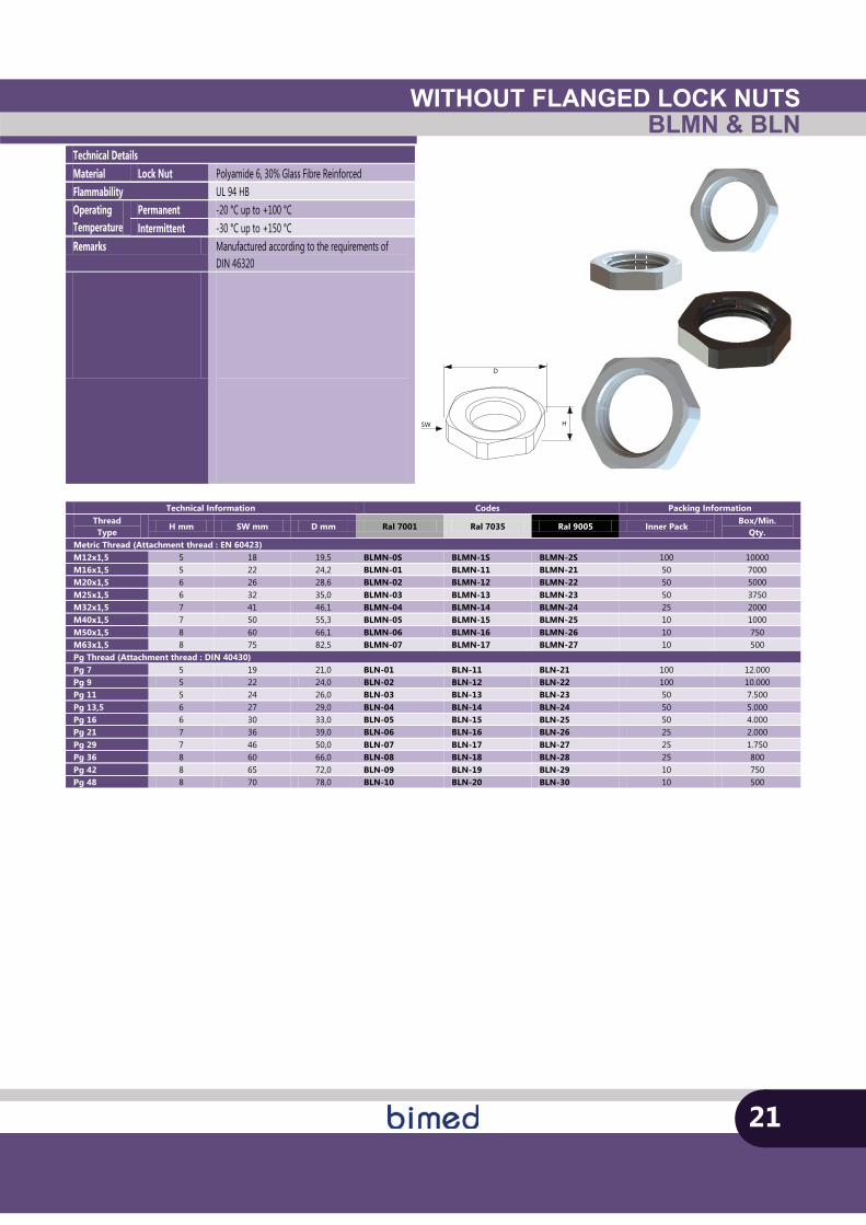
WITHOUT FLANGED LOCK NUTSBLMN & BLN
D
HSW
21
Technical Details Material Lock Nut Polyamide 6, 30% Glass Fibre Reinforced Flammability UL 94 HB Operating Temperature
Permanent -20 °C up to +100 °C Intermittent -30 °C up to +150 °C
Remarks Manufactured according to the requirements of DIN 46320
Technical Information Codes Packing Information Thread Type
H mm SW mm D mm Ral 7001 Ral 7035 Ral 9005 Inner Pack Box/Min.
Qty. Metric Thread (Attachment thread : EN 60423) M12x1,5 5 18 19,5 BLMN-0S BLMN-1S BLMN-2S 100 10000 M16x1,5 5 22 24,2 BLMN-01 BLMN-11 BLMN-21 50 7000 M20x1,5 6 26 28,6 BLMN-02 BLMN-12 BLMN-22 50 5000 M25x1,5 6 32 35,0 BLMN-03 BLMN-13 BLMN-23 50 3750 M32x1,5 7 41 46,1 BLMN-04 BLMN-14 BLMN-24 25 2000 M40x1,5 7 50 55,3 BLMN-05 BLMN-15 BLMN-25 10 1000 M50x1,5 8 60 66,1 BLMN-06 BLMN-16 BLMN-26 10 750 M63x1,5 8 75 82,5 BLMN-07 BLMN-17 BLMN-27 10 500 Pg Thread (Attachment thread : DIN 40430) Pg 7 5 19 21,0 BLN-01 BLN-11 BLN-21 100 12.000 Pg 9 5 22 24,0 BLN-02 BLN-12 BLN-22 100 10.000 Pg 11 5 24 26,0 BLN-03 BLN-13 BLN-23 50 7.500 Pg 13,5 6 27 29,0 BLN-04 BLN-14 BLN-24 50 5.000 Pg 16 6 30 33,0 BLN-05 BLN-15 BLN-25 50 4.000 Pg 21 7 36 39,0 BLN-06 BLN-16 BLN-26 25 2.000 Pg 29 7 46 50,0 BLN-07 BLN-17 BLN-27 25 1.750 Pg 36 8 60 66,0 BLN-08 BLN-18 BLN-28 25 800 Pg 42 8 65 72,0 BLN-09 BLN-19 BLN-29 10 750 Pg 48 8 70 78,0 BLN-10 BLN-20 BLN-30 10 500
TD
H
D
TL
D1
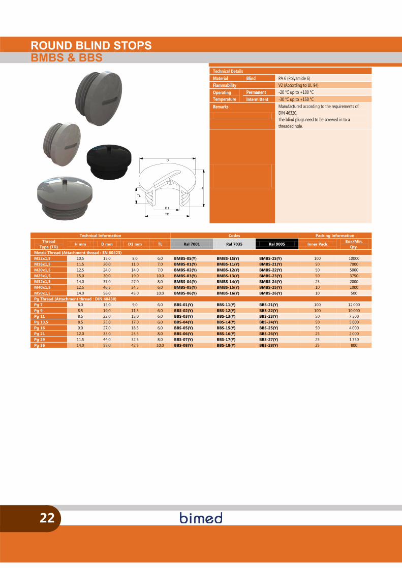
ROUND BLIND STOPSBMBS & BBS
22
Technical Details Material Blind PA 6 (Polyamide 6) Flammability V2 (According to UL 94) Operating Temperature
Permanent -20 °C up to +100 °C Intermittent -30 °C up to +150 °C
Remarks
Manufactured according to the requirements of DIN 46320. The blind plugs need to be screwed in to a threaded hole.
Technical Information Codes Packing Information Thread
Type (TD) H mm D mm D1 mm TL Ral 7001 Ral 7035 Ral 9005 Inner Pack
Box/Min. Qty.
Metric Thread (Attachment thread : EN 60423) M12x1,5 10,5 15,0 8,0 6,0 BMBS-0S(Y) BMBS-1S(Y) BMBS-2S(Y) 100 10000 M16x1,5 11,5 20,0 11,0 7,0 BMBS-01(Y) BMBS-11(Y) BMBS-21(Y) 50 7000 M20x1,5 12,5 24,0 14,0 7,0 BMBS-02(Y) BMBS-12(Y) BMBS-22(Y) 50 5000 M25x1,5 15,0 30,0 19,0 10,0 BMBS-03(Y) BMBS-13(Y) BMBS-23(Y) 50 3750 M32x1,5 14,0 37,0 27,0 8,0 BMBS-04(Y) BMBS-14(Y) BMBS-24(Y) 25 2000 M40x1,5 12,5 46,5 34,5 6,0 BMBS-05(Y) BMBS-15(Y) BMBS-25(Y) 10 1000 M50x1,5 14,0 56,0 45,0 10,0 BMBS-06(Y) BMBS-16(Y) BMBS-26(Y) 10 500 Pg Thread (Attachment thread : DIN 40430) Pg 7 8,0 15,0 9,0 6,0 BBS-01(Y) BBS-11(Y) BBS-21(Y) 100 12.000 Pg 9 8,5 19,0 11,5 6,0 BBS-02(Y) BBS-12(Y) BBS-22(Y) 100 10.000 Pg 11 8,5 22,0 15,0 6,0 BBS-03(Y) BBS-13(Y) BBS-23(Y) 50 7.500 Pg 13,5 8,5 25,0 17,0 6,0 BBS-04(Y) BBS-14(Y) BBS-24(Y) 50 5.000 Pg 16 9,0 27,0 18,5 6,0 BBS-05(Y) BBS-15(Y) BBS-25(Y) 50 4.000 Pg 21 12,0 33,0 23,5 8,0 BBS-06(Y) BBS-16(Y) BBS-26(Y) 25 2.000 Pg 29 11,5 44,0 32,5 8,0 BBS-07(Y) BBS-17(Y) BBS-27(Y) 25 1.750 Pg 36 14,0 55,0 42,5 10,0 BBS-08(Y) BBS-18(Y) BBS-28(Y) 25 800
e
H
D
TL
d
E
SW
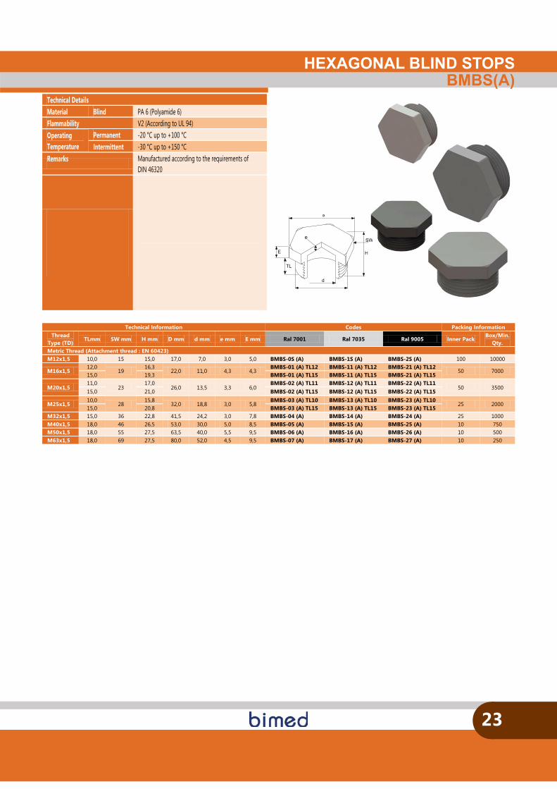
HEXAGONAL BLIND STOPSBMBS(A)
23
Technical Details Material Blind PA 6 (Polyamide 6) Flammability V2 (According to UL 94) Operating Temperature
Permanent -20 °C up to +100 °C Intermittent -30 °C up to +150 °C
Remarks Manufactured according to the requirements of DIN 46320
SW
Technical Information Codes Packing Information Thread
Type (TD) TLmm SW mm H mm D mm d mm e mm E mm Ral 7001 Ral 7035 Ral 9005 Inner Pack
Box/Min. Qty.
Metric Thread (Attachment thread : EN 60423) M12x1,5 10,0 15 15,0 17,0 7,0 3,0 5,0 BMBS-0S (A) BMBS-1S (A) BMBS-2S (A) 100 10000
M16x1,5 12,0
19 16,3
22,0 11,0 4,3 4,3 BMBS-01 (A) TL12 BMBS-11 (A) TL12 BMBS-21 (A) TL12
50 7000 15,0 19,3 BMBS-01 (A) TL15 BMBS-11 (A) TL15 BMBS-21 (A) TL15
M20x1,5 11,0
23 17,0
26,0 13,5 3,3 6,0 BMBS-02 (A) TL11 BMBS-12 (A) TL11 BMBS-22 (A) TL11
50 3500 15,0 21,0 BMBS-02 (A) TL15 BMBS-12 (A) TL15 BMBS-22 (A) TL15
M25x1,5 10,0
28 15,8
32,0 18,8 3,0 5,8 BMBS-03 (A) TL10 BMBS-13 (A) TL10 BMBS-23 (A) TL10
25 2000 15,0 20,8 BMBS-03 (A) TL15 BMBS-13 (A) TL15 BMBS-23 (A) TL15
M32x1,5 15,0 36 22,8 41,5 24,2 3,0 7,8 BMBS-04 (A) BMBS-14 (A) BMBS-24 (A) 25 1000 M40x1,5 18,0 46 26,5 53,0 30,0 5,0 8,5 BMBS-05 (A) BMBS-15 (A) BMBS-25 (A) 10 750 M50x1,5 18,0 55 27,5 63,5 40,0 5,5 9,5 BMBS-06 (A) BMBS-16 (A) BMBS-26 (A) 10 500 M63x1,5 18,0 69 27,5 80,0 52,0 4,5 9,5 BMBS-07 (A) BMBS-17 (A) BMBS-27 (A) 10 250
L
D
h
d
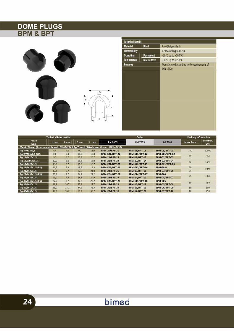
DOME PLUGSBPM & BPT
24
Technical Details Material Blind PA 6 (Polyamide 6) Flammability V2 (According to UL 94) Operating Temperature
Permanent -20 °C up to +100 °C Intermittent -30 °C up to +150 °C
Remarks Manufactured according to the requirements of DIN 46320
Technical Information Codes Packing Information Thread Type
d mm h mm D mm L mm Ral 9005 Ral 7035 Ral 7001 Inner Pack Box/Min.
Qty. Metric Thread (Attachment thread : EN 60423) & Pg Thread (Attachment thread : DIN 40430) Pg 7/M12x1,5 6,4 4,0 9,2 11,0 BPM-2S/BPT-21 BPM-1S/BPT-11 BPM-0S/BPT-01 100 10000 Pg 9/M16x1,5 (EU) 8,0 5,0 10,5 16,0 BPM-E21/BPT-22 BPM-E11/BPT-12 BPM-E01/BPT-02
50 7000 Pg 11/M16x1,5 9,7 5,7 13,3 20,7 BPM-21/BPT-23 BPM-11/BPT-13 BPM-01/BPT-03 Pg 13,5/M20x1,5 12,0 8,0 15,8 18,0 BPM-22/BPT-24 BPM-12/BPT-14 BPM-02/BPT-04
50 3500 Pg 16/M20x1,5 13,6 8,7 18,0 18,7 BPM-22L/BPT-25 BPM-12L/BPT-15 BPM-02L/BPT-05 Pg 21/M25x1,5 (EU) 16,5 7,3 19,9 18,3 BPM-E23/BPT-26 BPM-E13/BPT-16 BPM-E03/ 50
2000 Pg 21/M25x1,5 17,8 9,7 22,2 21,0 BPM-23/BPT-26 BPM-13/BPT-16 BPM-03/BPT-06 25 Pg 29/M32x1,5 (EU) 20,5 9,2 24,1 21,2 BPM-E24/BPT-27 BPM-E14/BPT-17 BPM-E04
25 1000 Pg 29/M32x1,5 25,0 9,9 28,8 24,9 BPM-24/BPT-27 BPM-14/BPT-17 BPM-04/BPT-07 Pg 36/M40x1,5 (EU) 27,5 9,2 32,0 25,2 BPM-E25/BPT-28 BPM-E15/BPT-18 BPM-E05
10 750 Pg 36/M40x1,5 31,8 10,7 37,3 27,7 BPM-25/BPT-28 BPM-15/BPT-18 BPM-05/BPT-08 Pg 42/M50x1,5 38,0 13,1 44,5 33,3 BPM-26/BPT-29 BPM-16/BPT-19 BPM-06/BPT-09 10 500 Pg 48/M63x1,5 44,2 16,2 51,7 39,2 BPM-27/BPT-30 BPM-17/BPT-20 BPM-07/BPT-10 10 250
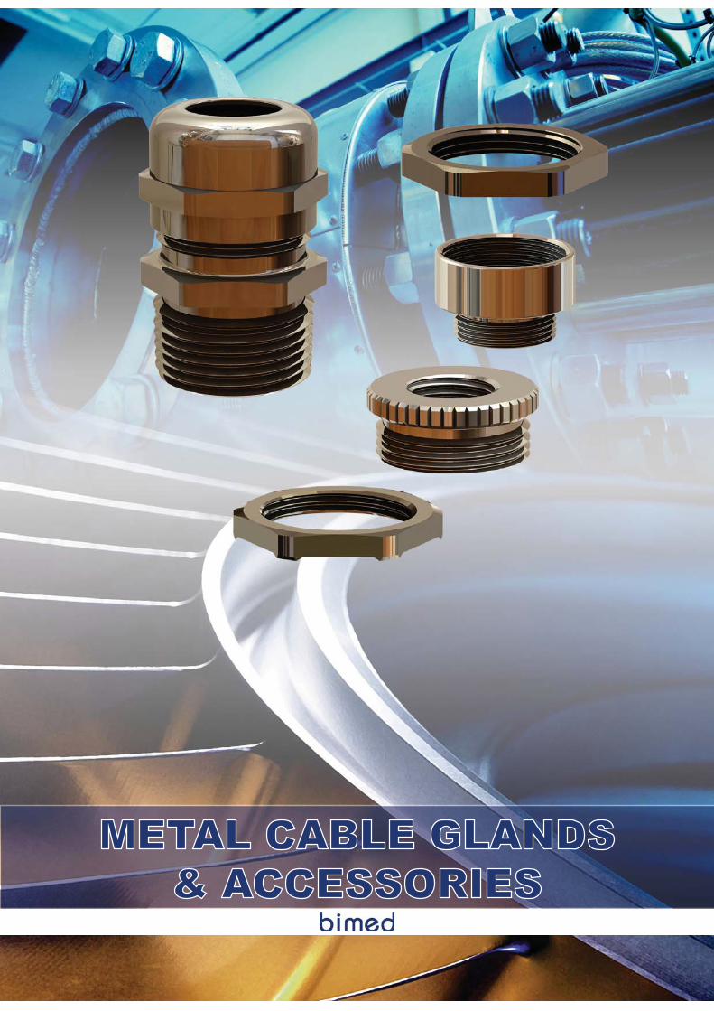
METAL CABLE GLANDS& ACCESSORIES
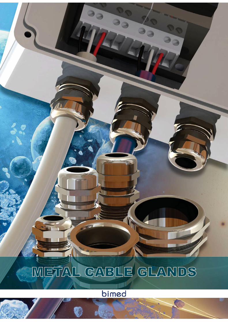
METAL CABLE GLANDS
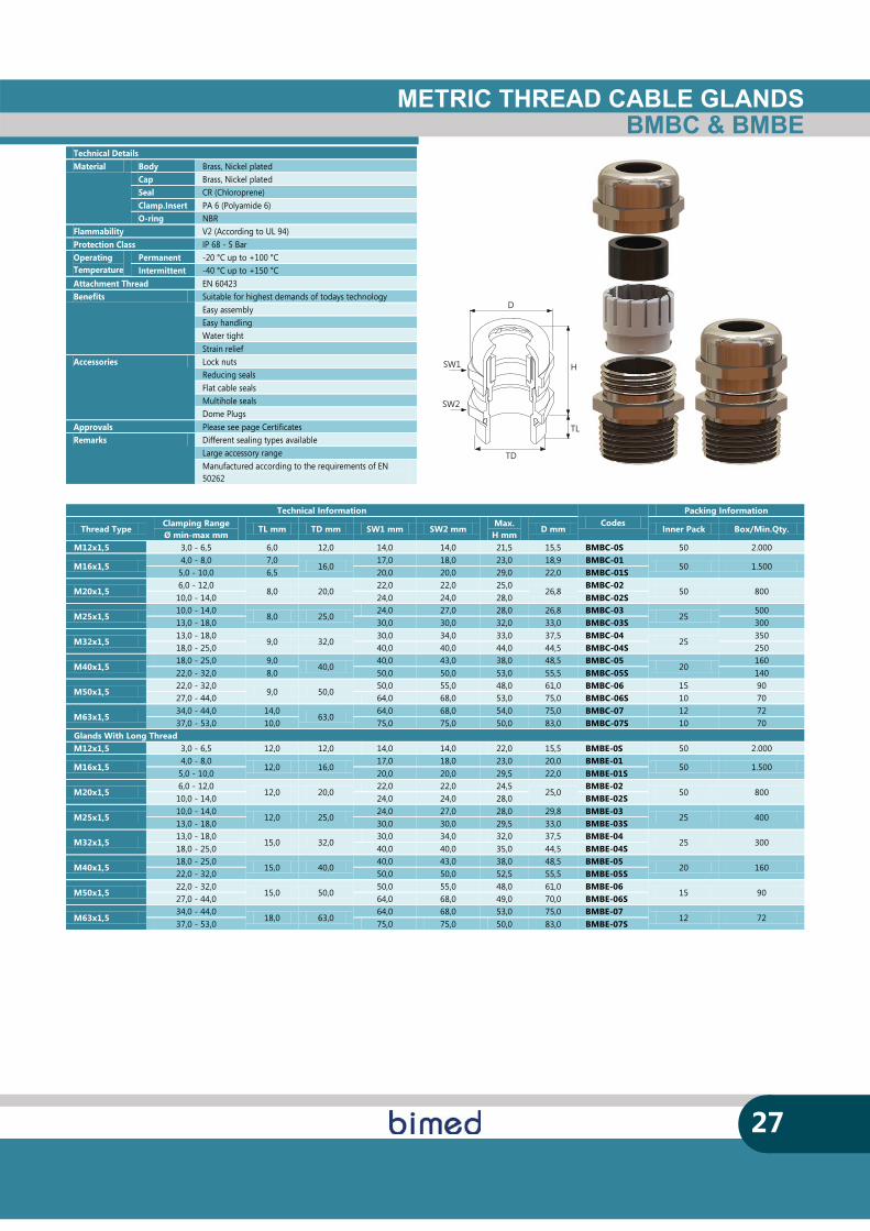
METRIC THREAD CABLE GLANDSBMBC & BMBE
27
SW1
SW2
D
TD
H
TL
Technical Details Material Body Brass, Nickel plated
Cap Brass, Nickel plated Seal CR (Chloroprene) Clamp.Insert PA 6 (Polyamide 6) O-ring NBR
Flammability V2 (According to UL 94) Protection Class IP 68 - 5 Bar Operating Temperature
Permanent -20 °C up to +100 °C Intermittent -40 °C up to +150 °C
Attachment Thread EN 60423 Benefits Suitable for highest demands of todays technology
Easy assembly Easy handling Water tight Strain relief
Accessories Lock nuts Reducing seals Flat cable seals Multihole seals Dome Plugs
Approvals Please see page Certificates Remarks Different sealing types available
Large accessory range Manufactured according to the requirements of EN 50262
Technical Information Codes
Packing Information
Thread Type Clamping Range Ø min-max mm
TL mm TD mm SW1 mm SW2 mm Max.
H mm D mm Inner Pack Box/Min.Qty.
M12x1,5 3,0 - 6,5 6,0 12,0 14,0 14,0 21,5 15,5 BMBC-0S 50 2.000
M16x1,5 4,0 - 8,0 7,0
16,0 17,0 18,0 23,0 18,9 BMBC-01
50 1.500 5,0 - 10,0 6,5 20,0 20,0 29,0 22,0 BMBC-01S
M20x1,5 6,0 - 12,0
8,0 20,0 22,0 22,0 25,0
26,8 BMBC-02
50 800 10,0 - 14,0 24,0 24,0 28,0 BMBC-02S
M25x1,5 10,0 - 14,0
8,0 25,0 24,0 27,0 28,0 26,8 BMBC-03
25 500
13,0 - 18,0 30,0 30,0 32,0 33,0 BMBC-03S 300
M32x1,5 13,0 - 18,0
9,0 32,0 30,0 34,0 33,0 37,5 BMBC-04
25 350
18,0 - 25,0 40,0 40,0 44,0 44,5 BMBC-04S 250
M40x1,5 18,0 - 25,0 9,0
40,0 40,0 43,0 38,0 48,5 BMBC-05
20 160
22,0 - 32,0 8,0 50,0 50,0 53,0 55,5 BMBC-05S 140
M50x1,5 22,0 - 32,0
9,0 50,0 50,0 55,0 48,0 61,0 BMBC-06 15 90
27,0 - 44,0 64,0 68,0 53,0 75,0 BMBC-06S 10 70
M63x1,5 34,0 - 44,0 14,0
63,0 64,0 68,0 54,0 75,0 BMBC-07 12 72
37,0 - 53,0 10,0 75,0 75,0 50,0 83,0 BMBC-07S 10 70 Glands With Long Thread M12x1,5 3,0 - 6,5 12,0 12,0 14,0 14,0 22,0 15,5 BMBE-0S 50 2.000
M16x1,5 4,0 - 8,0
12,0 16,0 17,0 18,0 23,0 20,0 BMBE-01
50 1.500 5,0 - 10,0 20,0 20,0 29,5 22,0 BMBE-01S
M20x1,5 6,0 - 12,0
12,0 20,0 22,0 22,0 24,5
25,0 BMBE-02
50 800 10,0 - 14,0 24,0 24,0 28,0 BMBE-02S
M25x1,5 10,0 - 14,0
12,0 25,0 24,0 27,0 28,0 29,8 BMBE-03
25 400 13,0 - 18,0 30,0 30,0 29,5 33,0 BMBE-03S
M32x1,5 13,0 - 18,0
15,0 32,0 30,0 34,0 32,0 37,5 BMBE-04
25 300 18,0 - 25,0 40,0 40,0 35,0 44,5 BMBE-04S
M40x1,5 18,0 - 25,0
15,0 40,0 40,0 43,0 38,0 48,5 BMBE-05
20 160 22,0 - 32,0 50,0 50,0 52,5 55,5 BMBE-05S
M50x1,5 22,0 - 32,0
15,0 50,0 50,0 55,0 48,0 61,0 BMBE-06
15 90 27,0 - 44,0 64,0 68,0 49,0 70,0 BMBE-06S
M63x1,5 34,0 - 44,0
18,0 63,0 64,0 68,0 53,0 75,0 BMBE-07
12 72 37,0 - 53,0 75,0 75,0 50,0 83,0 BMBE-07S
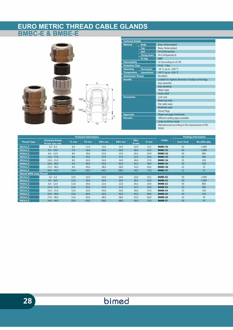
BMBC-E & BMBE-EEURO METRIC THREAD CABLE GLANDS
28
SW1
SW2
D
TD
H
TL
Technical Information Codes
Packing Information
Thread Type Clamping Range Ø min-max mm
TL mm TD mm SW1 mm SW2 mm Max.
H mm D mm Inner Pack Box/Min.Qty.
M12x1,5 3,0 - 6,5 6,0 12,0 14,0 14,0 22,0 15,5 BMBC-ES 50 2.000 M16x1,5 5,0 - 10,0 7,0 16,0 20,0 20,0 28,5 22,0 BMBC-E1 50 1.000 M20x1,5 6,0 - 12,0 8,0 20,0 22,0 22,0 26,5 24,0 BMBC-E2 50 800 M25x1,5 11,0 - 17,0 8,0 25,0 27,0 27,0 32,5 30,0 BMBC-E3 25 400 M32x1,5 15,0 - 21,0 8,0 32,0 34,0 34,0 36,0 37,0 BMBC-E4 25 250 M40x1,5 19,0 - 28,0 9,0 40,0 43,0 43,0 43,5 48,4 BMBC-E5 20 140 M50x1,5 27,0 - 38,0 9,0 50,0 58,0 58,0 52,0 64,0 BMBC-E6 12 72 M63x1,5 34,0 - 44,0 14,0 63,0 64,0 68,0 54,0 75,0 BMBC-E7 12 72 Glands With Long Thread M12x1,5 3,0 - 6,5 12,0 12,0 14,0 14,0 22,0 15,5 BMBE-ES 50 2.000 M16x1,5 5,0 - 10,0 12,0 16,0 20,0 20,0 28,5 22,0 BMBE-E1 50 1.000 M20x1,5 6,0 - 12,0 12,0 20,0 22,0 22,0 26,5 24,0 BMBE-E2 50 800 M25x1,5 11,0 - 17,0 12,0 25,0 27,0 27,0 32,5 30,0 BMBE-E3 25 400 M32x1,5 15,0 - 21,0 15,0 32,0 34,0 34,0 36,0 37,0 BMBE-E4 25 250 M40x1,5 19,0 - 28,0 15,0 40,0 43,0 43,0 43,5 48,4 BMBE-E5 20 120 M50x1,5 27,0 - 38,0 15,0 50,0 58,0 58,0 52,0 64,0 BMBE-E6 10 70 M63x1,5 34,0 - 44,0 15,0 63,0 64,0 68,0 54,0 75,0 BMBE-E7 10 70
Technical Details Material Body Brass, Nickel plated
Cap Brass, Nickel plated Seal CR (Chloroprene) Clamp.Insert PA 6 (Polyamide 6) O-ring NBR
Flammability V2 (According to UL 94) Protection Class IP 68 - 5 Bar Operating Temperature
Permanent -20 °C up to +100 °C Intermittent -40 °C up to +150 °C
Attachment Thread EN 60423 Benefits Suitable for highest demands of todays technology
Easy assembly Easy handling Water tight Strain relief
Accessories Lock nuts Reducing seals Flat cable seals Multihole seals Dome Plugs
Approvals Please see page Certificates Remarks Different sealing types available
Large accessory range Manufactured according to the requirements of EN 50262
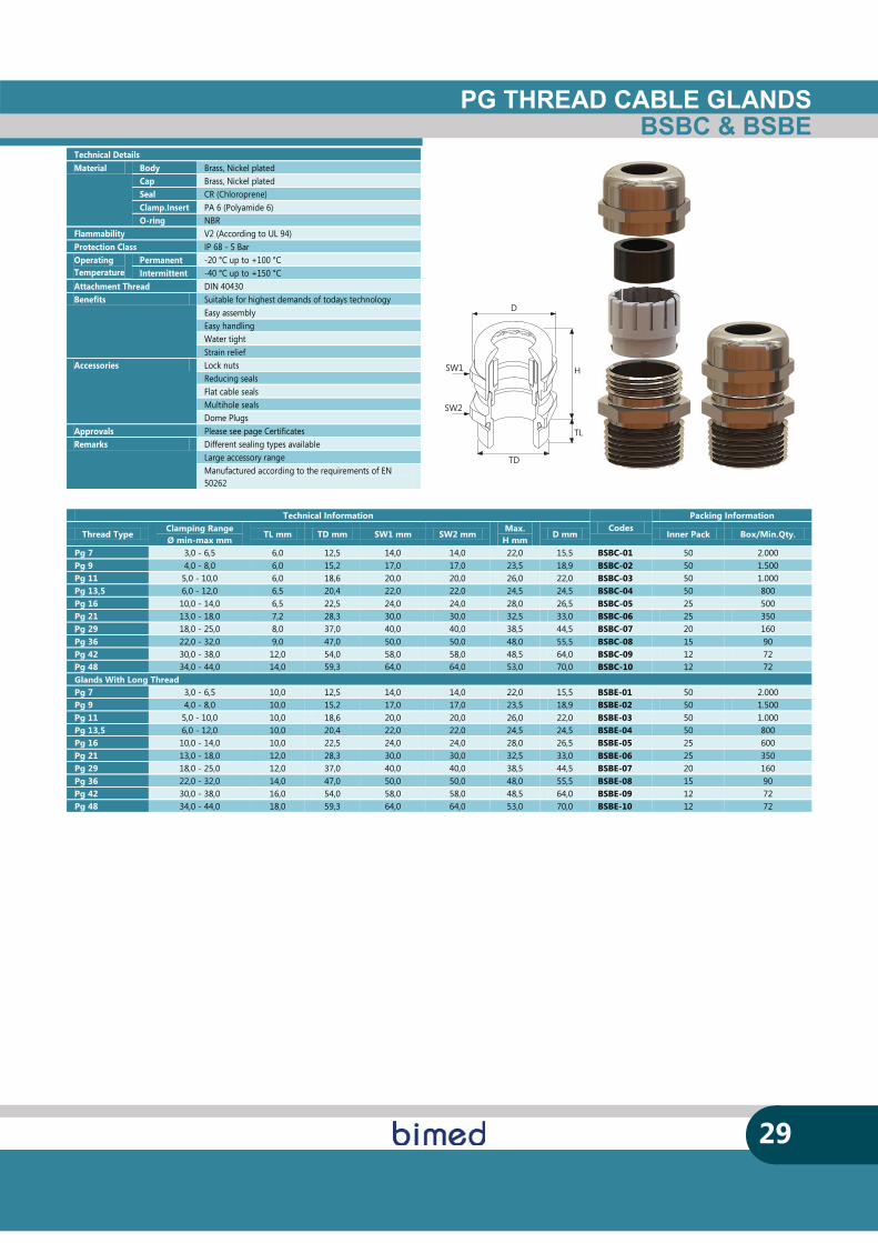
PG THREAD CABLE GLANDSBSBC & BSBE
29
SW1
SW2
D
TD
H
TL
Technical Information Codes
Packing Information
Thread Type Clamping Range Ø min-max mm
TL mm TD mm SW1 mm SW2 mm Max.
H mm D mm Inner Pack Box/Min.Qty.
Pg 7 3,0 - 6,5 6,0 12,5 14,0 14,0 22,0 15,5 BSBC-01 50 2.000 Pg 9 4,0 - 8,0 6,0 15,2 17,0 17,0 23,5 18,9 BSBC-02 50 1.500 Pg 11 5,0 - 10,0 6,0 18,6 20,0 20,0 26,0 22,0 BSBC-03 50 1.000 Pg 13,5 6,0 - 12,0 6,5 20,4 22,0 22,0 24,5 24,5 BSBC-04 50 800 Pg 16 10,0 - 14,0 6,5 22,5 24,0 24,0 28,0 26,5 BSBC-05 25 500 Pg 21 13,0 - 18,0 7,2 28,3 30,0 30,0 32,5 33,0 BSBC-06 25 350 Pg 29 18,0 - 25,0 8,0 37,0 40,0 40,0 38,5 44,5 BSBC-07 20 160 Pg 36 22,0 - 32,0 9,0 47,0 50,0 50,0 48,0 55,5 BSBC-08 15 90 Pg 42 30,0 - 38,0 12,0 54,0 58,0 58,0 48,5 64,0 BSBC-09 12 72 Pg 48 34,0 - 44,0 14,0 59,3 64,0 64,0 53,0 70,0 BSBC-10 12 72 Glands With Long Thread Pg 7 3,0 - 6,5 10,0 12,5 14,0 14,0 22,0 15,5 BSBE-01 50 2.000 Pg 9 4,0 - 8,0 10,0 15,2 17,0 17,0 23,5 18,9 BSBE-02 50 1.500 Pg 11 5,0 - 10,0 10,0 18,6 20,0 20,0 26,0 22,0 BSBE-03 50 1.000 Pg 13,5 6,0 - 12,0 10,0 20,4 22,0 22,0 24,5 24,5 BSBE-04 50 800 Pg 16 10,0 - 14,0 10,0 22,5 24,0 24,0 28,0 26,5 BSBE-05 25 600 Pg 21 13,0 - 18,0 12,0 28,3 30,0 30,0 32,5 33,0 BSBE-06 25 350 Pg 29 18,0 - 25,0 12,0 37,0 40,0 40,0 38,5 44,5 BSBE-07 20 160 Pg 36 22,0 - 32,0 14,0 47,0 50,0 50,0 48,0 55,5 BSBE-08 15 90 Pg 42 30,0 - 38,0 16,0 54,0 58,0 58,0 48,5 64,0 BSBE-09 12 72 Pg 48 34,0 - 44,0 18,0 59,3 64,0 64,0 53,0 70,0 BSBE-10 12 72
Technical Details Material Body Brass, Nickel plated
Cap Brass, Nickel plated Seal CR (Chloroprene) Clamp.Insert PA 6 (Polyamide 6) O-ring NBR
Flammability V2 (According to UL 94) Protection Class IP 68 - 5 Bar Operating Temperature
Permanent -20 °C up to +100 °C Intermittent -40 °C up to +150 °C
Attachment Thread DIN 40430 Benefits Suitable for highest demands of todays technology
Easy assembly Easy handling Water tight Strain relief
Accessories Lock nuts Reducing seals Flat cable seals Multihole seals Dome Plugs
Approvals Please see page Certificates Remarks Different sealing types available
Large accessory range Manufactured according to the requirements of EN 50262
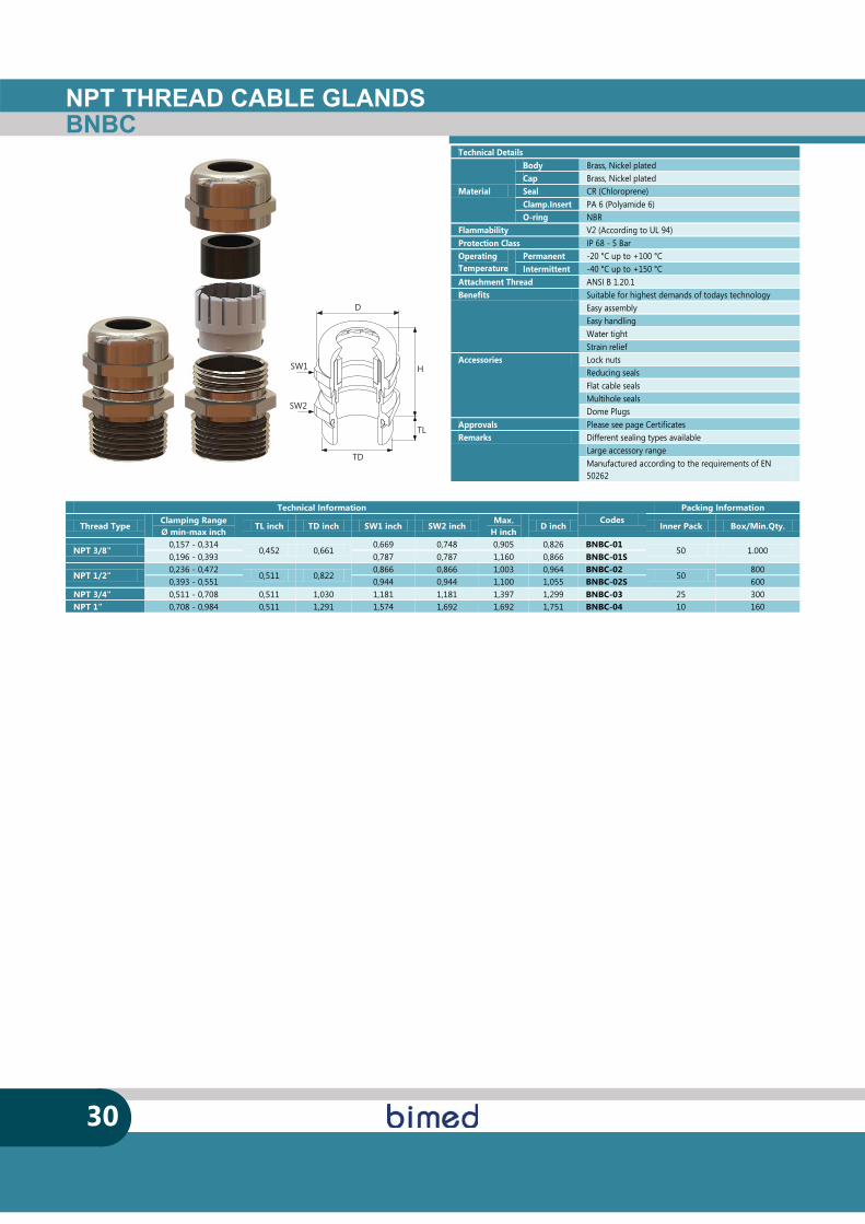
NPT THREAD CABLE GLANDSBNBC
30
SW1
SW2
D
TD
H
TL
Technical Information Codes
Packing Information
Thread Type Clamping Range Ø min-max inch
TL inch TD inch SW1 inch SW2 inch Max.
H inch D inch Inner Pack Box/Min.Qty.
NPT 3/8" 0,157 - 0,314
0,452 0,661 0,669 0,748 0,905 0,826 BNBC-01
50 1.000 0,196 - 0,393 0,787 0,787 1,160 0,866 BNBC-01S
NPT 1/2" 0,236 - 0,472
0,511 0,822 0,866 0,866 1,003 0,964 BNBC-02
50 800
0,393 - 0,551 0,944 0,944 1,100 1,055 BNBC-02S 600 NPT 3/4" 0,511 - 0,708 0,511 1,030 1,181 1,181 1,397 1,299 BNBC-03 25 300 NPT 1" 0,708 - 0,984 0,511 1,291 1,574 1,692 1,692 1,751 BNBC-04 10 160
Technical Details
Material
Body Brass, Nickel plated Cap Brass, Nickel plated Seal CR (Chloroprene) Clamp.Insert PA 6 (Polyamide 6) O-ring NBR
Flammability V2 (According to UL 94) Protection Class IP 68 - 5 Bar Operating Temperature
Permanent -20 °C up to +100 °C Intermittent -40 °C up to +150 °C
Attachment Thread ANSI B 1.20.1 Benefits Suitable for highest demands of todays technology
Easy assembly Easy handling Water tight Strain relief
Accessories Lock nuts Reducing seals Flat cable seals Multihole seals Dome Plugs
Approvals Please see page Certificates Remarks Different sealing types available
Large accessory range Manufactured according to the requirements of EN 50262
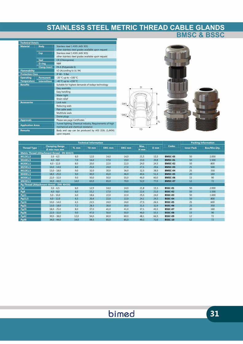
STAINLESS STEEL METRIC THREAD CABLE GLANDSBMSC & BSSC
31
SW1
SW2
D
TD
H
TL
Technical Information Codes
Packing Information
Thread Type Clamping Range Ø min-max mm
TL mm TD mm SW1 mm SW2 mm Max.
H mm D mm Inner Pack Box/Min.Qty.
Metric Thread (Attachment thread : EN 60423) M12X1,5 3,0 - 6,5 6,0 12,0 14,0 14,0 21,5 15,5 BMSC-0S 50 2.000 M16X1,5 4,0 - 8,0 7,0 16,0 17,0 19,0 23,0 20,8 BMSC-01 50 1.500 M20X1,5 6,0 - 12,0 8,0 20,0 22,0 22,0 24,0 24,5 BMSC-02 50 800 M25X1,5 10,0 - 14,0 8,0 25,0 24,0 27,0 27,5 29,6 BMSC-03 25 500 M32X1,5 13,0 - 18,0 9,0 32,0 30,0 36,0 32,5 38,9 BMSC-04 25 350 M40X1,5 18,0 - 25,0 9,0 40,0 41,0 46,0 40,6 51,4 BMSC-05 20 160 M50X1,5 22,0 - 32,0 9,0 50,0 50,0 55,0 46,0 60,0 BMSC-06 15 90 M63X1,5 34,0 - 44,0 14,0 63,0 65,0 70,0 52,0 77,0 BMSC-07 12 72 Pg Thread (Attachment thread : DIN 40430) Pg7 3,0 - 6,5 6,0 12,5 14,0 14,0 21,8 15,3 BSSC-01 50 2.000 Pg9 4,0 - 8,0 6,0 15,2 17,0 19,0 22,6 21,0 BSSC-02 50 1.500 Pg11 5,0 - 10,0 6,0 18,6 22,0 22,0 25,5 24,0 BSSC-03 50 1.000 Pg13,5 6,0 - 12,0 6,5 20,4 22,0 22,0 24,1 24,5 BSSC-04 50 800 Pg16 10,0 - 14,0 6,5 22,5 24,0 24,0 27,5 26,5 BSSC-05 25 600 Pg21 13,0 - 18,0 7,2 28,3 30,0 30,0 31,5 32,9 BSSC-06 25 350 Pg29 18,0 - 25,0 8,0 37,0 41,0 41,0 37,1 45,5 BSSC-07 20 160 Pg36 22,0 - 32,0 9,0 47,0 50,0 50,0 46,0 55,5 BSSC-08 15 90 Pg42 30,0 - 38,0 12,0 54,0 60,0 60,0 48,1 66,5 BSSC-09 12 72 Pg48 34,0 - 44,0 14,0 59,3 65,0 65,0 49,3 72,0 BSSC-10 12 72
Technical Details Material Body Stainless steel 1.4305 (AISI 303)
other stainless steel grades available upon request Cap Stainless steel 1.4305 (AISI 303)
other stainless steel grades available upon request Seal CR (Chloroprene) O-ring NBR Clamp.Insert PA 6 (Polyamide 6)
Flammability V2 (According to UL 94) Protection Class IP 68 - 5 Bar Operating Temperature
Permanent -20 °C up to +100 °C Intermittent -40 °C up to +150 °C
Benefits Suitable for highest demands of todays technology Easy assembly Easy handling Water tight Strain relief
Accessories Lock nuts Reducing seals Flat cable seals Multihole seals Dome plugs
Approvals Please see page Certificates
Application Areas Tunnel lighting, Chemical industry, Requirements of high mechanical and chemical resistance
Remarks Body and cap can be produced by AISI 316L (1,4404) upon request.
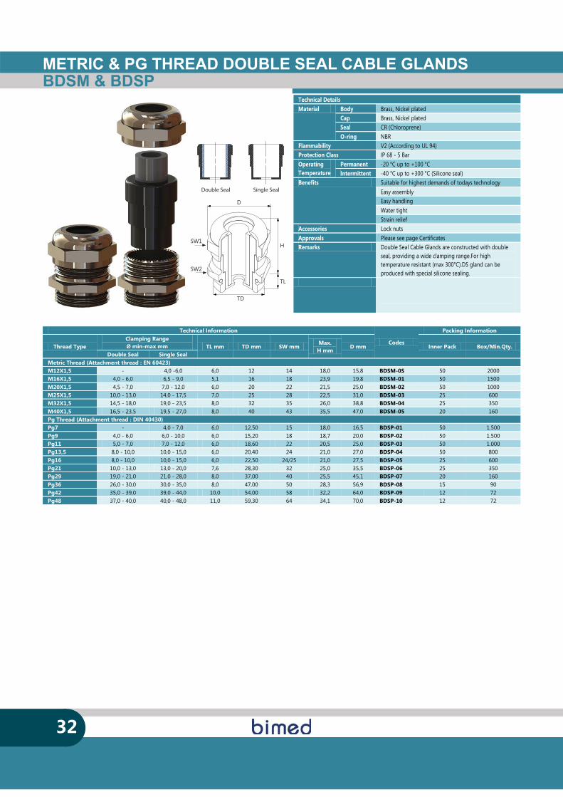
METRIC & PG THREAD DOUBLE SEAL CABLE GLANDSBDSM & BDSP
Double Seal Single Seal
32
SW1
SW2
D
TD
H
TL
Technical Information
Codes
Packing Information
Thread Type Clamping Range Ø min-max mm TL mm TD mm SW mm
Max. H mm
D mm Inner Pack Box/Min.Qty. Double Seal Single Seal
Metric Thread (Attachment thread : EN 60423) M12X1,5 - 4,0 -6,0 6,0 12 14 18,0 15,8 BDSM-0S 50 2000 M16X1,5 4,0 - 6,0 6,5 - 9,0 5,1 16 18 23,9 19,8 BDSM-01 50 1500 M20X1,5 4,5 - 7,0 7,0 - 12,0 6,0 20 22 21,5 25,0 BDSM-02 50 1000 M25X1,5 10,0 - 13,0 14,0 - 17,5 7,0 25 28 22,5 31,0 BDSM-03 25 600 M32X1,5 14,5 - 18,0 19,0 - 23,5 8,0 32 35 26,0 38,8 BDSM-04 25 350 M40X1,5 16,5 - 23,5 19,5 - 27,0 8,0 40 43 35,5 47,0 BDSM-05 20 160 Pg Thread (Attachment thread : DIN 40430) Pg7 - 4,0 - 7,0 6,0 12,50 15 18,0 16,5 BDSP-01 50 1.500 Pg9 4,0 - 6,0 6,0 - 10,0 6,0 15,20 18 18,7 20,0 BDSP-02 50 1.500 Pg11 5,0 - 7,0 7,0 - 12,0 6,0 18,60 22 20,5 25,0 BDSP-03 50 1.000 Pg13,5 8,0 - 10,0 10,0 - 15,0 6,0 20,40 24 21,0 27,0 BDSP-04 50 800 Pg16 8,0 - 10,0 10,0 - 15,0 6,0 22,50 24/25 21,0 27,5 BDSP-05 25 600 Pg21 10,0 - 13,0 13,0 - 20,0 7,6 28,30 32 25,0 35,5 BDSP-06 25 350 Pg29 19,0 - 21,0 21,0 - 28,0 8,0 37,00 40 25,5 45,1 BDSP-07 20 160 Pg36 26,0 - 30,0 30,0 - 35,0 8,0 47,00 50 28,3 56,9 BDSP-08 15 90 Pg42 35,0 - 39,0 39,0 - 44,0 10,0 54,00 58 32,2 64,0 BDSP-09 12 72 Pg48 37,0 - 40,0 40,0 - 48,0 11,0 59,30 64 34,1 70,0 BDSP-10 12 72
Technical Details Material Body Brass, Nickel plated
Cap Brass, Nickel plated Seal CR (Chloroprene) O-ring NBR
Flammability V2 (According to UL 94) Protection Class IP 68 - 5 Bar Operating Temperature
Permanent -20 °C up to +100 °C Intermittent -40 °C up to +300 °C (Silicone seal)
Benefits Suitable for highest demands of todays technology Easy assembly Easy handling Water tight Strain relief
Accessories Lock nuts Approvals Please see page Certificates Remarks Double Seal Cable Glands are constructed with double
seal, providing a wide clamping range.For high temperature resistant (max 300°C).DS gland can be produced with special silicone sealing.
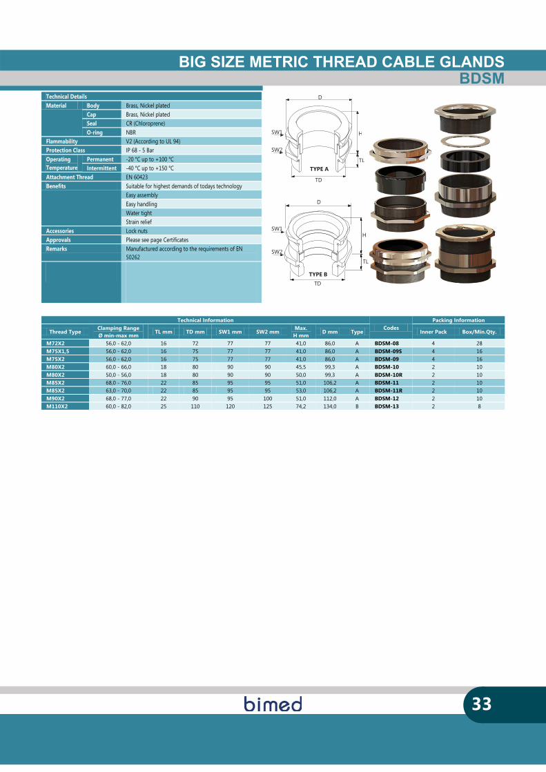
BIG SIZE METRIC THREAD CABLE GLANDSBDSM
33
TD
TL
H
D
SW1
SW2
TYPE B
SW1
SW2
D
TD
H
TLTYPE A
TL
H
H
TL
Technical Information Codes
Packing Information
Thread Type Clamping Range Ø min-max mm
TL mm TD mm SW1 mm SW2 mm Max.
H mm D mm Type Inner Pack Box/Min.Qty.
M72X2 56,0 - 62,0 16 72 77 77 41,0 86,0 A BDSM-08 4 28 M75X1,5 56,0 - 62,0 16 75 77 77 41,0 86,0 A BDSM-09S 4 16 M75X2 56,0 - 62,0 16 75 77 77 41,0 86,0 A BDSM-09 4 16 M80X2 60,0 - 66,0 18 80 90 90 45,5 99,3 A BDSM-10 2 10 M80X2 50,0 - 56,0 18 80 90 90 50,0 99,3 A BDSM-10R 2 10 M85X2 68,0 - 76,0 22 85 95 95 51,0 106,2 A BDSM-11 2 10 M85X2 63,0 - 70,0 22 85 95 95 53,0 106,2 A BDSM-11R 2 10 M90X2 68,0 - 77,0 22 90 95 100 51,0 112,0 A BDSM-12 2 10 M110X2 60,0 - 82,0 25 110 120 125 74,2 134,0 B BDSM-13 2 8
Technical Details Material Body Brass, Nickel plated
Cap Brass, Nickel plated Seal CR (Chloroprene) O-ring NBR
Flammability V2 (According to UL 94) Protection Class IP 68 - 5 Bar Operating Temperature
Permanent -20 °C up to +100 °C Intermittent -40 °C up to +150 °C
Attachment Thread EN 60423 Benefits Suitable for highest demands of todays technology
Easy assembly Easy handling Water tight Strain relief
Accessories Lock nuts Approvals Please see page Certificates Remarks Manufactured according to the requirements of EN
50262
EMC CABLE GLANDS
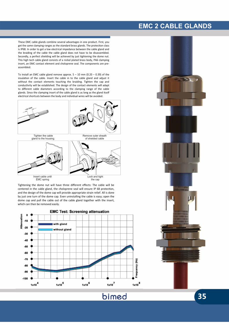
EMC 2 CABLE GLANDS
Tighten the cablegland to the housing.
Remove outer sheathof shielded cable
Insert cable untilEMC spring
Lock and tightthe cap
These EMC cable glands combine several advantages in one product. First, you get the same clamping ranges as the standard brass glands. The protec�on class is IP68. In order to get a low electrical impedance between the cable gland and the braiding of the cable the cable gland does not have to be disassembled. Secondly, a perfect shielding will be achieved by just �ghtening the dome nut. This high tech cable gland consists of a nickel plated brass body, PA6 clamping insert, an EMC contact element and choloprene seal. The components are pre-assembled. To install an EMC cable gland remove approx. 5 – 10 mm (0.20 – 0.39) of the insula�on of the cable. Insert the cable in to the cable gland and adjust it without the contact elements touching the braiding. Tighten the cap and conduc�vity will be established. The design of the contact elements will adapt to di�erent cable diameters according to the clamping range of the cable glands. Since the clamping insert of the cable gland is as long as the gland itself electrical shortcuts between the body and individual wires will be avoided.
Tightening the dome nut will have three di�erent e�ects: The cable will be centered in the cable gland, the choloprene seal will ensure IP 68 protec�on, and the design of the dome cap will provide appropriate strain relief. All is done by just one turn of the dome cap. Even uninstalling the cable is easy; open the dome cap and pull the cable out of the cable gland together with the insert, which can then be removed easily.
35
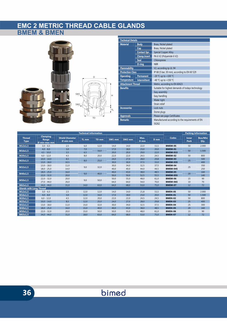
EMC 2 METRIC THREAD CABLE GLANDSBMEM & BMEN
36
SW1
SW2
D
TD
H
TL
Technical Details Material Body Brass, Nickel plated
Cap Brass, Nickel plated Contact Spr. Special Copper Alloy Clamp.Insert PA 6 V2 (Polyamide 6 V2) Seal Chloroprene O-ring NBR
Flammability V2, according tp UL 94 Protection Class IP 68 (5 bar, 30 min), according to EN 60 529 Operating Temperature
Permanent -20 °C up to +100 °C Intermittent -40 °C up to +150 °C
Attachment Thread Metric, according to EN 60423 Benefits Suitable for highest demands of todays technology
Easy assembly Easy handling Water tight Strain relief
Accessories Lock nuts Dome plugs
Approvals Please see page Certificates Remarks Manufactured according to the requirements of EN
50262
Technical Information
Codes
Packing Information
Thread Type
Clamping Range
Ø min-max mm
Shield Diameter Ø min mm
TL mm TD mm SW1 mm SW2 mm Max.
H mm D mm
Inner Pack
Box/MinQty.
M12x1,5 3,0 - 6,5 2,5 6,0 12,0 14,0 14,0 22,0 15,5 BMEM-0S 50 2.000
M16x1,5 4,0 - 8,0 3,0 7,0
16,0 17,0 18,0 23,0 20,0 BMEM-01
50 1.500 4,5 - 10,0 3,5 6,5 20,0 20,0 29,0 22,0 BMEM-01S
M20x1,5 6,0 - 12,0 4,5 8,0 20,0 22,0 22,0 24,5 24,5 BMEM-02 50 800
M25x1,5 10,0 - 14,0 8,5
8,0 25,0 24,0 27,0 28,0 29,8 BMEM-03
25 500
13,0 - 18,0 10,5 30,0 30,0 37,5 33,0 BMEM-03S 400
M32x1,5 13,0 - 18,0 11,0
9,0 32,0 30,0 34,0 32,5 37,5 BMEM-04
25 350
18,0 - 25,0 14,0 40,0 40,0 44,0 44,5 BMEM-04S 250
M40x1,5 18,0 - 25,0 16,0
9,0 40,0 40,0 43,0 38,0 48,5 BMEM-05
20 160
22,0 - 32,0 20,0 50,0 50,0 52,5 55,5 BMEM-05S 140
M50x1,5 22,0 - 32,0 20,0
9,0 50,0 50,0 55,0 48,0 61,0 BMEM-06 15 90
27,0 - 44,0 26,0 64,0 64,0 54,0 70,0 BMEM-06S 10 70 M63x1,5 34,0 - 44,0 31,0 14,0 63,0 64,0 68,0 53,0 75,0 BMEM-07 12 72 Glands with Long Thread M12x1,5 3,0 - 6,5 2,5 12,0 12,0 14,0 14,0 21,8 15,5 BMEN-0S 50 2.000 M16x1,5 4,0 - 8,0 3,0 12,0 16,0 17,0 18,0 23,0 20,0 BMEN-01 50 1.500 M20x1,5 6,0 - 12,0 4,5 12,0 20,0 22,0 22,0 24,5 24,5 BMEN-02 50 800 M25x1,5 10,0 - 14,0 8,5 12,0 25,0 24,0 27,0 28,0 29,8 BMEN-03 25 400 M32x1,5 13,0 - 18,0 11,0 15,0 32,0 30,0 34,0 32,5 37,5 BMEN-04 25 300 M40x1,5 18,0 - 25,0 16,0 15,0 40,0 40,0 43,0 38,0 48,5 BMEN-05 20 160 M50x1,5 22,0 - 32,0 20,0 15,0 50,0 50,0 55,0 48,0 61,0 BMEN-06 15 90 M63x1,5 34,0 - 44,0 31,0 18,0 63,0 64,0 68,0 53,0 75,0 BMEN-07 12 72
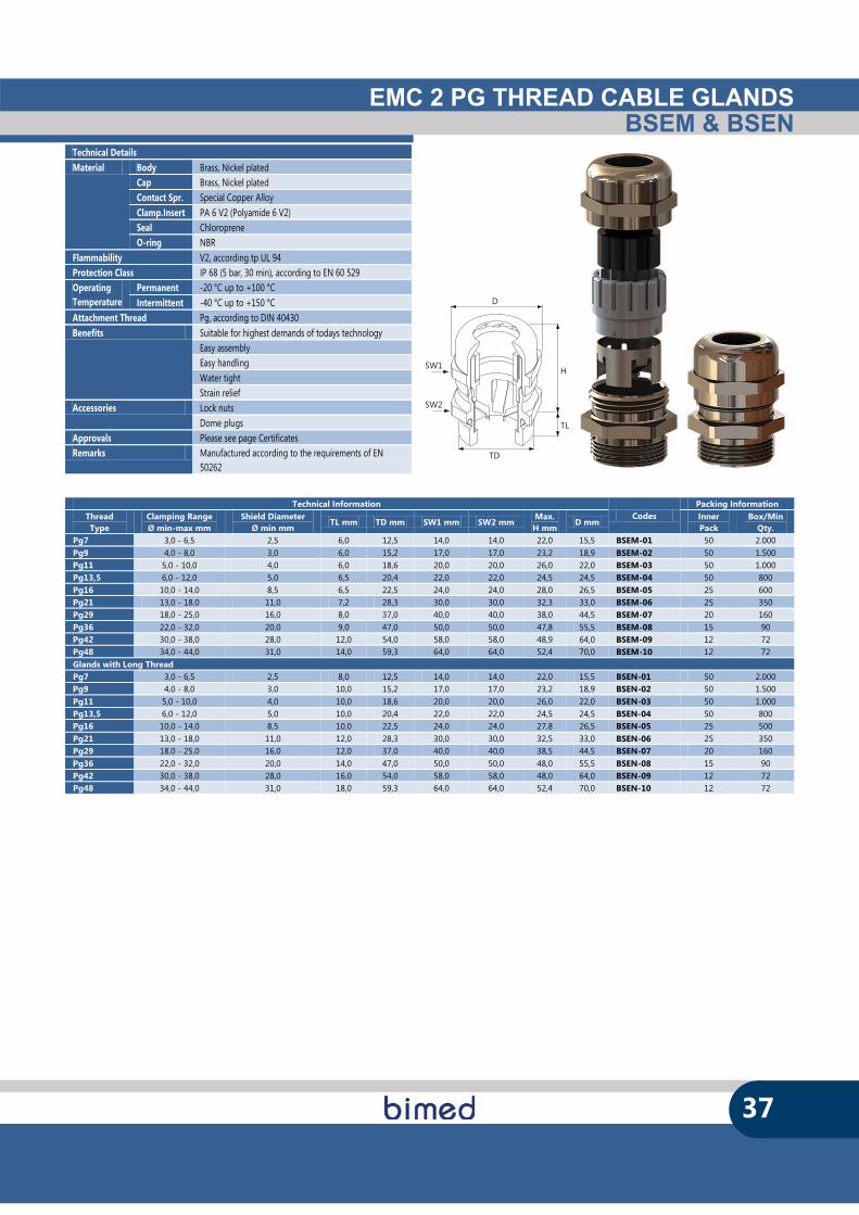
EMC 2 PG THREAD CABLE GLANDSBSEM & BSEN
37
SW1
SW2
D
TD
H
TL
Technical Information Codes
Packing Information Thread Type
Clamping Range Ø min-max mm
Shield Diameter Ø min mm
TL mm TD mm SW1 mm SW2 mm Max.
H mm D mm
Inner Pack
Box/MinQty.
Pg7 3,0 - 6,5 2,5 6,0 12,5 14,0 14,0 22,0 15,5 BSEM-01 50 2.000 Pg9 4,0 - 8,0 3,0 6,0 15,2 17,0 17,0 23,2 18,9 BSEM-02 50 1.500 Pg11 5,0 - 10,0 4,0 6,0 18,6 20,0 20,0 26,0 22,0 BSEM-03 50 1.000 Pg13,5 6,0 - 12,0 5,0 6,5 20,4 22,0 22,0 24,5 24,5 BSEM-04 50 800 Pg16 10,0 - 14,0 8,5 6,5 22,5 24,0 24,0 28,0 26,5 BSEM-05 25 600 Pg21 13,0 - 18,0 11,0 7,2 28,3 30,0 30,0 32,3 33,0 BSEM-06 25 350 Pg29 18,0 - 25,0 16,0 8,0 37,0 40,0 40,0 38,0 44,5 BSEM-07 20 160 Pg36 22,0 - 32,0 20,0 9,0 47,0 50,0 50,0 47,8 55,5 BSEM-08 15 90 Pg42 30,0 - 38,0 28,0 12,0 54,0 58,0 58,0 48,9 64,0 BSEM-09 12 72 Pg48 34,0 - 44,0 31,0 14,0 59,3 64,0 64,0 52,4 70,0 BSEM-10 12 72 Glands with Long Thread Pg7 3,0 - 6,5 2,5 8,0 12,5 14,0 14,0 22,0 15,5 BSEN-01 50 2.000 Pg9 4,0 - 8,0 3,0 10,0 15,2 17,0 17,0 23,2 18,9 BSEN-02 50 1.500 Pg11 5,0 - 10,0 4,0 10,0 18,6 20,0 20,0 26,0 22,0 BSEN-03 50 1.000 Pg13,5 6,0 - 12,0 5,0 10,0 20,4 22,0 22,0 24,5 24,5 BSEN-04 50 800 Pg16 10,0 - 14,0 8,5 10,0 22,5 24,0 24,0 27,8 26,5 BSEN-05 25 500 Pg21 13,0 - 18,0 11,0 12,0 28,3 30,0 30,0 32,5 33,0 BSEN-06 25 350 Pg29 18,0 - 25,0 16,0 12,0 37,0 40,0 40,0 38,5 44,5 BSEN-07 20 160 Pg36 22,0 - 32,0 20,0 14,0 47,0 50,0 50,0 48,0 55,5 BSEN-08 15 90 Pg42 30,0 - 38,0 28,0 16,0 54,0 58,0 58,0 48,0 64,0 BSEN-09 12 72 Pg48 34,0 - 44,0 31,0 18,0 59,3 64,0 64,0 52,4 70,0 BSEN-10 12 72
Technical Details Material Body Brass, Nickel plated
Cap Brass, Nickel plated Contact Spr. Special Copper Alloy Clamp.Insert PA 6 V2 (Polyamide 6 V2) Seal Chloroprene O-ring NBR
Flammability V2, according tp UL 94 Protection Class IP 68 (5 bar, 30 min), according to EN 60 529 Operating Temperature
Permanent -20 °C up to +100 °C Intermittent -40 °C up to +150 °C
Attachment Thread Pg, according to DIN 40430 Benefits Suitable for highest demands of todays technology
Easy assembly Easy handling Water tight Strain relief
Accessories Lock nuts Dome plugs
Approvals Please see page Certificates Remarks Manufactured according to the requirements of EN
50262
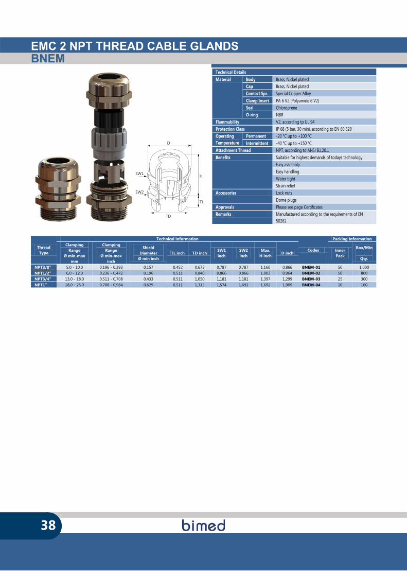
EMC 2 NPT THREAD CABLE GLANDSBNEM
38
SW1
SW2
D
TD
H
TL
Thread Type
Technical Information
Codes
Packing Information Clamping
Range Ø min-max
mm
Clamping Range
Ø min-max inch
Shield Diameter
Ø min inch TL inch TD inch
SW1 inch
SW2 inch
Max. H inch
D inch Inner Pack
Box/Min.
Qty.
NPT3/8" 5,0 - 10,0 0,196 - 0,393 0,157 0,452 0,675 0,787 0,787 1,160 0,866 BNEM-01 50 1.000 NPT1/2" 6,0 - 12,0 0,236 - 0,472 0,196 0,511 0,840 0,866 0,866 1,003 0,964 BNEM-02 50 800 NPT3/4" 13,0 - 18,0 0,511 - 0,708 0,433 0,511 1,050 1,181 1,181 1,397 1,299 BNEM-03 25 300 NPT1" 18,0 - 25,0 0,708 - 0,984 0,629 0,511 1,315 1,574 1,692 1,692 1,909 BNEM-04 10 160
Technical Details Material Body Brass, Nickel plated
Cap Brass, Nickel plated Contact Spr. Special Copper Alloy Clamp.Insert PA 6 V2 (Polyamide 6 V2) Seal Chloroprene O-ring NBR
Flammability V2, according tp UL 94 Protection Class IP 68 (5 bar, 30 min), according to EN 60 529 Operating Temperature
Permanent -20 °C up to +100 °C Intermittent -40 °C up to +150 °C
Attachment Thread NPT, according to ANSI B1.20.1 Benefits Suitable for highest demands of todays technology
Easy assembly Easy handling Water tight Strain relief
Accessories Lock nuts Dome plugs
Approvals Please see page Certificates Remarks Manufactured according to the requirements of EN
50262
EMC 3 CABLE GLANDS
39
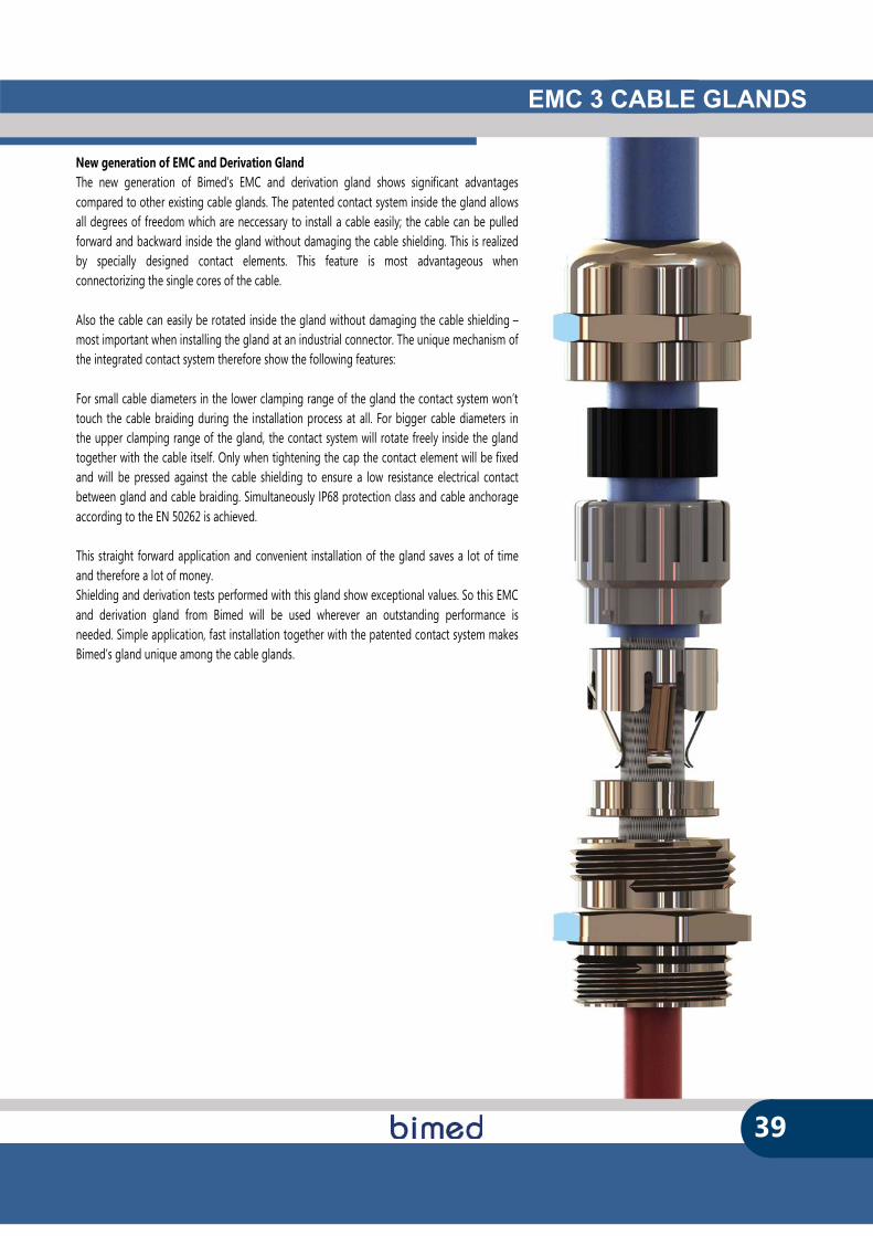
New generation of EMC and Derivation Gland The new generation of Bimed’s EMC and derivation gland shows significant advantages compared to other existing cable glands. The patented contact system inside the gland allows all degrees of freedom which are neccessary to install a cable easily; the cable can be pulled forward and backward inside the gland without damaging the cable shielding. This is realized by specially designed contact elements. This feature is most advantageous when connectorizing the single cores of the cable. Also the cable can easily be rotated inside the gland without damaging the cable shielding – most important when installing the gland at an industrial connector. The unique mechanism of the integrated contact system therefore show the following features: For small cable diameters in the lower clamping range of the gland the contact system won’t touch the cable braiding during the installation process at all. For bigger cable diameters in the upper clamping range of the gland, the contact system will rotate freely inside the gland together with the cable itself. Only when tightening the cap the contact element will be fixed and will be pressed against the cable shielding to ensure a low resistance electrical contact between gland and cable braiding. Simultaneously IP68 protection class and cable anchorage according to the EN 50262 is achieved. This straight forward application and convenient installation of the gland saves a lot of time and therefore a lot of money. Shielding and derivation tests performed with this gland show exceptional values. So this EMC and derivation gland from Bimed will be used wherever an outstanding performance is needed. Simple application, fast installation together with the patented contact system makes Bimed’s gland unique among the cable glands.

EMC 3 EURO METRIC THREAD CABLE GLANDSBMEM-E
40
SW1
SW2
D
TD
H
TL
Technical Details Material Body Brass, Nickel plated
Cap Brass, Nickel plated Contact Spr. Special Copper Alloy Clamp.Insert PA 6 V2 (Polyamide 6 V2) Seal Chloroprene O-ring NBR
Flammability V2, according tp UL 94 Protection Class IP 68 (5 bar, 30 min), according to EN 60 529 Operating Temperature
Permanent -20 °C up to +100 °C Intermittent -40 °C up to +150 °C
Attachment Thread Metric, according to EN 60423 Benefits Suitable for highest demands of todays technology
Easy assembly Easy handling Water tight Strain relief
Accessories Lock nuts Dome plugs Approvals Please see page Certificates Remarks Fast and easy installation.
Adapts to different cable shields. Reliable connection. High shielding factor. Mechanical values according to EN 50262. Clamping range identical to other Bimed glands. 360° brand touching. Manufactured according to the requirements of EN 50262
Technical Information Codes
Packing Information Thread Type
Clamping Range Ø min-max mm
Shield Diameter Ø min mm
TL mm TD mm SW1 mm SW2 mm Max.
H mm D mm Inner Pack
Box/Min. Qty.
M12x1,5 3,0 - 6,5 2,5 6,0 12,0 14,0 14,0 22,0 15,5 BMEM-ES 50 2.000 M16x1,5 5,0 - 10,0 4,0 7,0 16,0 20,0 20,0 29,0 22,0 BMEM-E1 50 1.000 M20x1,5 6,0 - 12,0 5,0 8,0 20,0 22,0 22,0 27,5 24,5 BMEM-E2 50 800 M25x1,5 11,0 - 17,0 9,5 8,0 25,0 27,0 27,0 30,7 30,0 BMEM-E3 25 400 M32x1,5 15,0 - 21,0 13,5 8,0 32,0 34,0 34,0 38,0 37,0 BMEM-E4 25 250 M40x1,5 19,0 - 28,0 17,0 9,0 40,0 43,0 43,0 43,0 48,5 BMEM-E5 20 140 M50x1,5 27,0 - 38,0 25,0 9,0 50,0 58,0 58,0 54,5 64,0 BMEM-E6 12 72 M63x1,5 34,0 - 44,0 31,0 14,0 63,0 64,0 68,0 57,0 75,0 BMEM-E7 12 72
As Supplied With Min. Cable Diameter With Max. Cable Diameter
A2
EMC 4 CABLE GLANDS
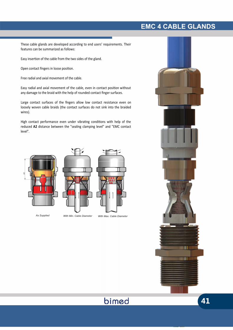
These cable glands are developed according to end users' requirements. Their features can be summarized as follows: Easy inser�on of the cable from the two sides of the gland. Open contact �ngers in loose posi�on. Free radial and axial movement of the cable. Easy radial and axial movement of the cable, even in contact posi�on without any damage to the braid with the help of rounded contact �nger surfaces. Large contact surfaces of the �ngers allow low contact resistance even on loosely woven cable braids (the contact surfaces do not sink into the braided wires). High contact performance even under vibra�ng condi�ons with help of the reduced A2 distance between the "sealing clamping level" and "EMC contact level".
41
EMC 4 METRIC THREAD CABLE GLANDSBMEM-E
42
SW1
SW2
D
TD
H
TL
SW1
SW2
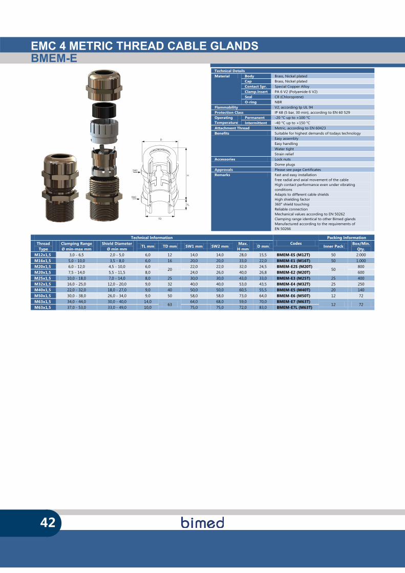
Technical Details Material Body Brass, Nickel plated
Cap Brass, Nickel plated Contact Spr. Special Copper Alloy Clamp.Insert PA 6 V2 (Polyamide 6 V2) Seal CR (Chloroprene) O-ring NBR
Flammability V2, according tp UL 94 Protection Class IP 68 (5 bar, 30 min), according to EN 60 529 Operating Temperature
Permanent -20 °C up to +100 °C Intermittent -40 °C up to +150 °C
Attachment Thread Metric, according to EN 60423 Benefits Suitable for highest demands of todays technology
Easy assembly Easy handling Water tight Strain relief
Accessories Lock nuts Dome plugs
Approvals Please see page Certificates Remarks Fast and easy installation
Free radial and axial movement of the cable High contact performance even under vibrating conditions Adapts to different cable shields High shielding factor 360° shield touching Reliable connection Mechanical values according to EN 50262 Clamping range identical to other Bimed glands Manufactured according to the requirements of EN 50266
Technical Information Codes
Packing Information Thread Type
Clamping Range Ø min-max mm
Shield Diameter Ø min mm
TL mm TD mm SW1 mm SW2 mm Max.
H mm D mm Inner Pack
Box/Min. Qty.
M12x1,5 3,0 - 6,5 2,0 - 5,0 6,0 12 14,0 14,0 28,0 15,5 BMEM-ES (M12T) 50 2.000 M16x1,5 5,0 - 10,0 3,5 - 8,0 6,0 16 20,0 20,0 33,0 22,0 BMEM-E1 (M16T) 50 1.000 M20x1,5 6,0 - 12,0 4,5 - 10,0 6,0
20 22,0 22,0 32,0 24,5 BMEM-E2S (M20T)
50 800
M20x1,5 7,5 - 14,0 5,5 - 11,5 8,0 24,0 26,0 40,0 26,8 BMEM-E2 (M20T) 600 M25x1,5 10,0 - 18,0 7,0 - 14,0 8,0 25 30,0 30,0 43,0 33,0 BMEM-E3 (M25T) 25 400 M32x1,5 16,0 - 25,0 12,0 - 20,0 9,0 32 40,0 40,0 53,0 43,5 BMEM-E4 (M32T) 25 250 M40x1,5 22,0 - 32,0 18,0 - 27,0 9,0 40 50,0 50,0 60,5 55,5 BMEM-E5 (M40T) 20 140 M50x1,5 30,0 - 38,0 26,0 - 34,0 9,0 50 58,0 58,0 73,0 64,0 BMEM-E6 (M50T) 12 72 M63x1,5 34,0 - 44,0 30,0 - 40,0 14,0
63 64,0 68,0 59,0 70,0 BMEM-E7 (M63T)
12 72 M63x1,5 37,0 - 53,0 33,0 - 49,0 10,0 75,0 75,0 72,0 83,0 BMEM-E7L (M63T)
EMC 4 PG THREAD CABLE GLANDSBSEM-E
43
SW1
SW2
D
TD
H
TL
Technical Information Codes
Packing Information Thread Type
Clamping Range Ø min-max mm
Shield Diameter Ø min mm
TL mm TD mm SW1 mm
SW2 mm
Max. H mm
D mm Inner Pack
Box/Min Qty.
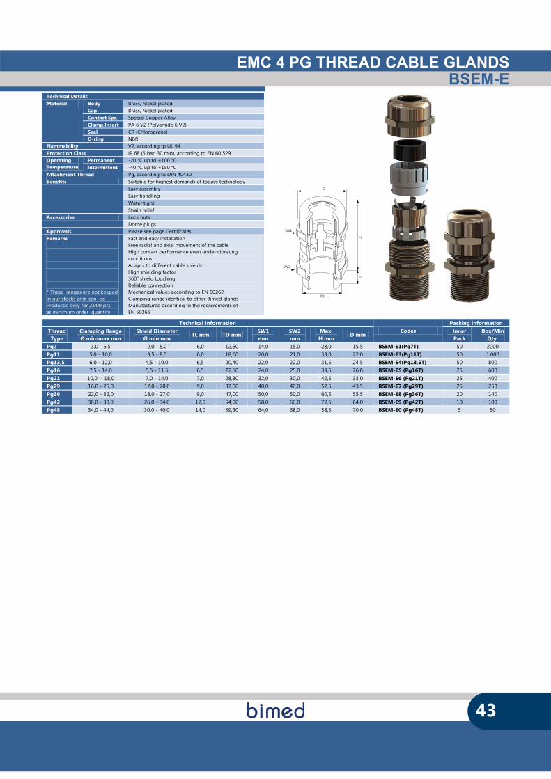
Pg7 3,0 - 6,5 2,0 - 5,0 6,0 12,50 14,0 15,0 28,0 15,5 BSEM-E1(Pg7T) 50 2000 Pg11 5,0 - 10,0 3,5 - 8,0 6,0 18,60 20,0 21,0 33,0 22,0 BSEM-E3(Pg11T) 50 1.000 Pg13,5 6,0 - 12,0 4,5 - 10,0 6,5 20,40 22,0 22,0 31,5 24,5 BSEM-E4(Pg13,5T) 50 800 Pg16 7,5 - 14,0 5,5 - 11,5 6,5 22,50 24,0 25,0 39,5 26,8 BSEM-E5 (Pg16T) 25 600 Pg21 10,0 - 18,0 7,0 - 14,0 7,0 28,30 32,0 30,0 42,5 33,0 BSEM-E6 (Pg21T) 25 400 Pg29 16,0 - 25,0 12,0 - 20,0 9,0 37,00 40,0 40,0 52,5 43,5 BSEM-E7 (Pg29T) 25 250 Pg36 22,0 - 32,0 18,0 - 27,0 9,0 47,00 50,0 50,0 60,5 55,5 BSEM-E8 (Pg36T) 20 140 Pg42 30,0 - 38,0 26,0 - 34,0 12,0 54,00 58,0 60,0 72,5 64,0 BSEM-E9 (Pg42T) 10 100 Pg48 34,0 - 44,0 30,0 - 40,0 14,0 59,30 64,0 68,0 58,5 70,0 BSEM-E0 (Pg48T) 5 50
Technical Details Material Body Brass, Nickel plated
Cap Brass, Nickel plated Contact Spr. Special Copper Alloy Clamp.Insert PA 6 V2 (Polyamide 6 V2) Seal CR (Chloroprene) O-ring NBR
Flammability V2, according tp UL 94 Protection Class IP 68 (5 bar, 30 min), according to EN 60 529 Operating Temperature
Permanent -20 °C up to +100 °C Intermittent -40 °C up to +150 °C
Attachment Thread Pg, according to DIN 40430 Benefits Suitable for highest demands of todays technology
Easy assembly Easy handling Water tight Strain relief
Accessories Lock nuts Dome plugs
Approvals Please see page Certificates Remarks * These ranges are not keeped In our stocks and can be Produced only for 2.000 pcs as minimum order quantity.
Fast and easy installation Free radial and axial movement of the cable High contact performance even under vibrating conditions Adapts to different cable shields High shielding factor 360° shield touching Reliable connection Mechanical values according to EN 50262 Clamping range identical to other Bimed glands Manufactured according to the requirements of EN 50266

EMC 4 NPT THREAD CABLE GLANDSBNEM-E
44
SW1
SW2
D
TD
H
TL
SW1
SW2
Thread Type (TD)
Technical Information Codes
Packing Information Clamping Range Ø min-max mm
Clamping Range Ø min-max inch
Shield Diameter Ø min inch
TL inch SW1 inch SW2 inch Max.
H inch D mm Inner Pack
Box/Min. Qty.
NPT 1/4" 3,0 - 6,5 0,118 - 0,255 0,078 - 0,196 0,453 0,551 0,590 1,102 15,5 BNEM-ES (NPT1/4"T) 50 2.000 NPT 3/8" 5,0 - 10,0 0,196 - 0,393 0,137 - 0,314 0,453 0,787 0,787 1,300 18,9 BNEM-E1 (NPT3/8"T) 50 1.000 NPT 1/2" 6,0 - 12,0 0,236 - 0,472 0,177 - 0,393
0,591 0,867 0,867 1,478
22,0 BNEM-E2S (NPT1/2"T)
50 800
NPT 1/2" 7,5 - 14,0 0,295 - 0,551 0,216 - 0,452 0,945 0,945 1,556 BNEM-E2 (NPT1/2"T) 600 NPT 3/4" 10,0 - 18,0 0,393 - 0,708 0,275 - 0,551 0,591 1,182 1,182 1,673 24,5 BNEM-E3 (NPT3/4"T) 25 400 NPT 1" 16,0 - 25,0 0,629 - 0,984 0,472 - 0,787 0,788 1,575 1,575 2,067 26,8 BNEM-E4 (NPT1"T) 25 250 NPT 1 1/4" 22,0 - 32,0 0,866 - 1,259 0,708 - 1,062 0,788 1,969 1,969 2,441 33,0 BNEM-E5 (NPT1 1/4"T) 20 140 NPT 1 1/2" 30,0 - 38,0 1,181 - 1,496 1,023 - 1,338 0,867 2,284 2,284 2,835 43,5 BNEM-E6 (NPT1 1/2"T) 10 100 NPT 2" 34,0 - 44,0 1,338 - 1,732 1,181 - 1,574 0,867 2,520 2,678 2,815 55,5 BNEM-E7 (NPT2"T) 5 50
Technical Details Material Body Brass, Nickel plated
Cap Brass, Nickel plated Contact Spr. Special Copper Alloy Clamp.Insert PA 6 V2 (Polyamide 6 V2) Seal CR (Chloroprene) O-ring NBR
Flammability V2, according tp UL 94 Protection Class IP 68 (5 bar, 30 min), according to EN 60 529 Operating Temperature
Permanent -20 °C up to +100 °C Intermittent -40 °C up to +150 °C
Attachment Thread NPT, according to ANSI B1.20.1 Benefits Suitable for highest demands of todays technology
Easy assembly Easy handling Water tight Strain relief
Accessories Lock nuts Dome plugs
Approvals Please see page Certificates Remarks * These ranges are not keeped In our stocks and can be Produced only for 2.000 pcs as minimum order quantity.
Fast and easy installation Free radial and axial movement of the cable High contact performance even under vibrating conditions Adapts to different cable shields High shielding factor 360° shield touching Reliable connection Mechanical values according to EN 50262 Clamping range identical to other Bimed glands Manufactured according to the requirements of EN 50266
METAL ACCESSORIES
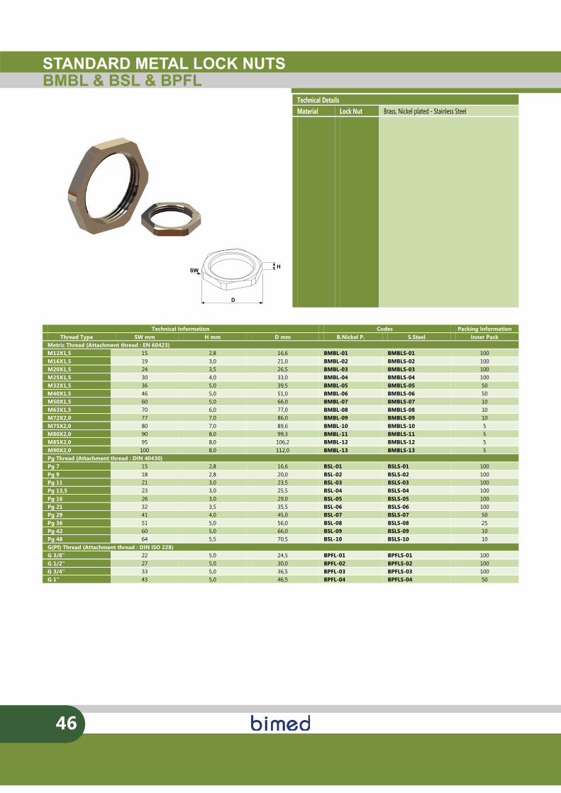
STANDARD METAL LOCK NUTSBMBL & BSL & BPFL
D
HSW
46
Technical Information Codes Packing Information Thread Type SW mm H mm D mm B.Nickel P. S.Steel Inner Pack
Metric Thread (Attachment thread : EN 60423) M12X1,5 15 2,8 16,6 BMBL-01 BMBLS-01 100 M16X1,5 19 3,0 21,0 BMBL-02 BMBLS-02 100 M20X1,5 24 3,5 26,5 BMBL-03 BMBLS-03 100 M25X1,5 30 4,0 33,0 BMBL-04 BMBLS-04 100 M32X1,5 36 5,0 39,5 BMBL-05 BMBLS-05 50 M40X1,5 46 5,0 51,0 BMBL-06 BMBLS-06 50 M50X1,5 60 5,0 66,0 BMBL-07 BMBLS-07 10 M63X1,5 70 6,0 77,0 BMBL-08 BMBLS-08 10 M72X2,0 77 7,0 86,0 BMBL-09 BMBLS-09 10 M75X2,0 80 7,0 89,6 BMBL-10 BMBLS-10 5 M80X2,0 90 8,0 99,3 BMBL-11 BMBLS-11 5 M85X2,0 95 8,0 106,2 BMBL-12 BMBLS-12 5 M90X2,0 100 8,0 112,0 BMBL-13 BMBLS-13 5 Pg Thread (Attachment thread : DIN 40430) Pg 7 15 2,8 16,6 BSL-01 BSLS-01 100 Pg 9 18 2,8 20,0 BSL-02 BSLS-02 100 Pg 11 21 3,0 23,5 BSL-03 BSLS-03 100 Pg 13,5 23 3,0 25,5 BSL-04 BSLS-04 100 Pg 16 26 3,0 29,0 BSL-05 BSLS-05 100 Pg 21 32 3,5 35,5 BSL-06 BSLS-06 100 Pg 29 41 4,0 45,0 BSL-07 BSLS-07 50 Pg 36 51 5,0 56,0 BSL-08 BSLS-08 25 Pg 42 60 5,0 66,0 BSL-09 BSLS-09 10 Pg 48 64 5,5 70,5 BSL-10 BSLS-10 10 G(Pf) Thread (Attachment thread : DIN ISO 228) G 3/8" 22 5,0 24,5 BPFL-01 BPFLS-01 100 G 1/2" 27 5,0 30,0 BPFL-02 BPFLS-02 100 G 3/4" 33 5,0 36,5 BPFL-03 BPFLS-03 100 G 1" 43 5,0 46,5 BPFL-04 BPFLS-04 50
Technical Details Material Lock Nut Brass, Nickel plated - Stainless Steel
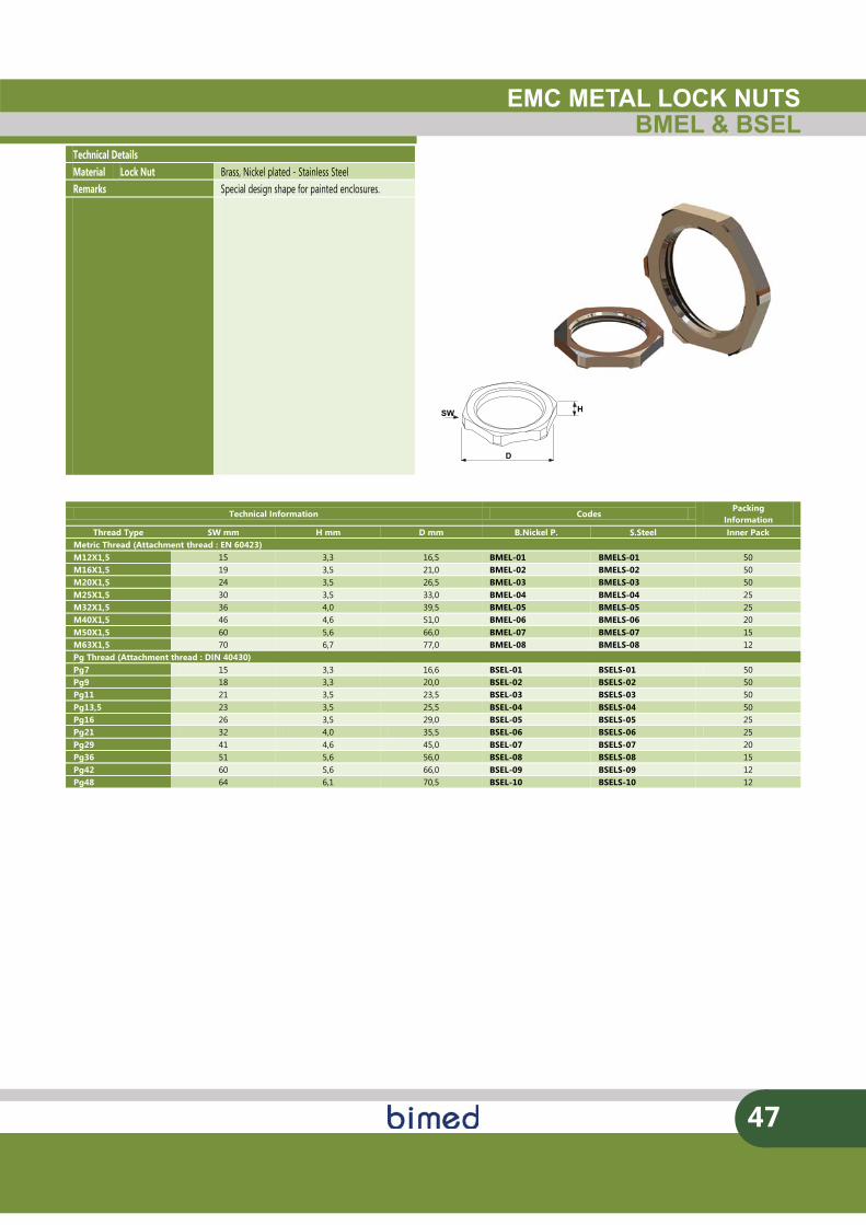
EMC METAL LOCK NUTSBMEL & BSEL
D
HSW
47
Technical Details Material Lock Nut Brass, Nickel plated - Stainless Steel Remarks Special design shape for painted enclosures. Remarks Special design shape for painted enclosures.
Technical Information Codes
Packing Information
Thread Type SW mm H mm D mm B.Nickel P. S.Steel Inner Pack Metric Thread (Attachment thread : EN 60423) M12X1,5 15 3,3 16,5 BMEL-01 BMELS-01 50 M16X1,5 19 3,5 21,0 BMEL-02 BMELS-02 50 M20X1,5 24 3,5 26,5 BMEL-03 BMELS-03 50 M25X1,5 30 3,5 33,0 BMEL-04 BMELS-04 25 M32X1,5 36 4,0 39,5 BMEL-05 BMELS-05 25 M40X1,5 46 4,6 51,0 BMEL-06 BMELS-06 20 M50X1,5 60 5,6 66,0 BMEL-07 BMELS-07 15 M63X1,5 70 6,7 77,0 BMEL-08 BMELS-08 12 Pg Thread (Attachment thread : DIN 40430) Pg7 15 3,3 16,6 BSEL-01 BSELS-01 50 Pg9 18 3,3 20,0 BSEL-02 BSELS-02 50 Pg11 21 3,5 23,5 BSEL-03 BSELS-03 50 Pg13,5 23 3,5 25,5 BSEL-04 BSELS-04 50 Pg16 26 3,5 29,0 BSEL-05 BSELS-05 25 Pg21 32 4,0 35,5 BSEL-06 BSELS-06 25 Pg29 41 4,6 45,0 BSEL-07 BSELS-07 20 Pg36 51 5,6 56,0 BSEL-08 BSELS-08 15 Pg42 60 5,6 66,0 BSEL-09 BSELS-09 12 Pg48 64 6,1 70,5 BSEL-10 BSELS-10 12
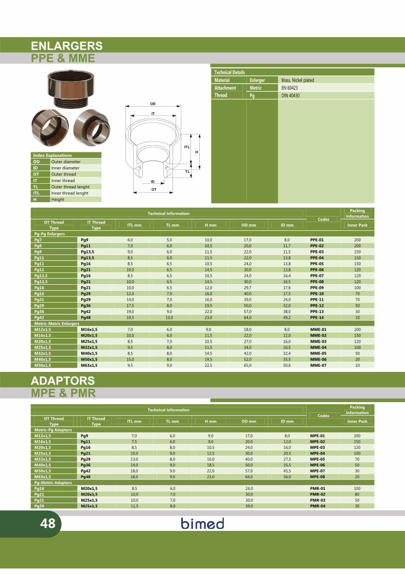
ENLARGERSPPE & MME
48
OD
IT
OT
ID
TL
ITLH
Technical Details Material Enlarger Brass, Nickel plated Attachment Thread
Metric EN 60423 Pg DIN 40430
Index Explanations OD Outer diameter ID Inner diameter OT Outer thread IT Inner thread TL Outer thread lenght ITL Inner thread lenght H Height
ADAPTORSMPE & PMR
Technical Information Codes
Packing Information
OT Thread Type
IT Thread Type
ITL mm TL mm H mm OD mm ID mm Inner Pack
Pg-Pg Enlargers Pg7 Pg9 6,0 5,0 10,0 17,0 8,0 PPE-01 200 Pg9 Pg11 7,0 6,0 10,5 20,0 11,7 PPE-02 200 Pg9 Pg13,5 9,0 6,0 11,5 22,0 11,5 PPE-03 150 Pg11 Pg13,5 8,5 6,0 11,5 22,0 13,8 PPE-04 150 Pg11 Pg16 8,5 6,5 10,5 24,0 13,8 PPE-05 150 Pg11 Pg21 10,0 6,5 14,5 30,0 13,8 PPE-06 120 Pg13,5 Pg16 8,5 6,5 10,5 24,0 16,4 PPE-07 120 Pg13,5 Pg21 10,0 6,5 14,5 30,0 16,5 PPE-08 120 Pg16 Pg21 10,0 6,5 12,0 29,7 17,6 PPE-09 100 Pg16 Pg29 12,0 7,0 16,0 40,0 17,5 PPE-10 70 Pg21 Pg29 14,0 7,0 16,0 39,0 24,0 PPE-11 70 Pg29 Pg36 17,5 8,0 19,5 50,0 32,0 PPE-12 50 Pg36 Pg42 19,0 9,0 22,0 57,0 38,0 PPE-13 30 Pg42 Pg48 19,5 10,0 23,0 64,0 49,2 PPE-14 10 Metric-Metric Enlargers M12x1,5 M16x1,5 7,0 6,0 9,0 18,0 8,0 MME-01 200 M16x1,5 M20x1,5 10,0 6,0 11,5 22,0 12,0 MME-02 150 M20x1,5 M25x1,5 8,5 7,0 10,5 27,0 16,0 MME-03 120 M25x1,5 M32x1,5 9,5 8,0 11,5 34,0 20,5 MME-04 100 M32x1,5 M40x1,5 8,5 8,0 14,5 42,0 32,4 MME-05 50 M40x1,5 M50x1,5 15,0 8,0 19,5 52,0 35,5 MME-06 20 M50x1,5 M63x1,5 9,5 9,0 22,5 65,0 50,6 MME-07 10
Technical Information Codes
Packing Information
OT Thread Type
IT Thread Type
ITL mm TL mm H mm OD mm ID mm Inner Pack
Metric-Pg Adaptors M12x1,5 Pg9 7,0 6,0 9,0 17,0 8,0 MPE-01 200 M16x1,5 Pg11 7,5 6,0 9,0 20,0 12,0 MPE-02 150 M20x1,5 Pg16 8,5 8,0 10,5 24,0 16,0 MPE-03 120 M25x1,5 Pg21 10,0 9,0 12,5 30,0 20,5 MPE-04 100 M32x1,5 Pg29 13,0 8,0 16,0 40,0 27,5 MPE-05 70 M40x1,5 Pg36 14,0 9,0 18,5 50,0 35,5 MPE-06 50 M50x1,5 Pg42 18,0 9,0 22,0 57,0 45,5 MPE-07 30 M63x1,5 Pg48 18,0 9,0 23,0 64,0 56,0 MPE-08 20 Pg-Metric Adaptors Pg16 M20x1,5 8,5 6,0 24,0 PMR-01 100 Pg21 M20x1,5 10,0 7,0 30,0 PMR-02 80 Pg21 M25x1,5 10,0 7,0 30,0 PMR-03 50 Pg29 M25x1,5 11,5 8,0 39,0 PMR-04 30
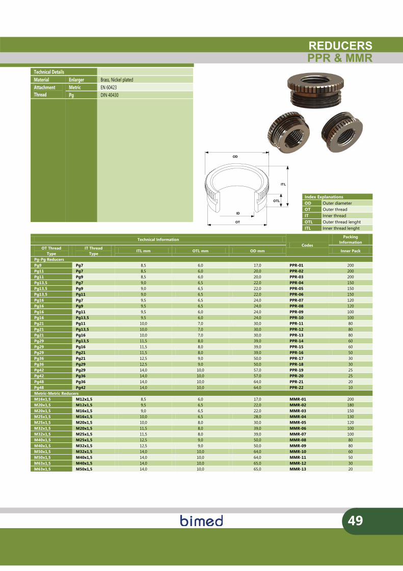
OD
OT
ID
OTL
ITL
REDUCERSPPR & MMR
49
Technical Details Material Enlarger Brass, Nickel plated Attachment Thread
Metric EN 60423 Pg DIN 40430
Index Explanations OD Outer diameter OT Outer thread IT Inner thread OTL Outer thread lenght
ITL Inner thread lenght
Technical Information
Codes
Packing Information
OT Thread Type
IT Thread Type
ITL mm OTL mm OD mm Inner Pack
Pg-Pg Reducers Pg9 Pg7 8,5 6,0 17,0 PPR-01 200 Pg11 Pg7 8,5 6,0 20,0 PPR-02 200 Pg11 Pg9 8,5 6,0 20,0 PPR-03 200 Pg13,5 Pg7 9,0 6,5 22,0 PPR-04 150 Pg13,5 Pg9 9,0 6,5 22,0 PPR-05 150 Pg13,5 Pg11 9,0 6,5 22,0 PPR-06 150 Pg16 Pg7 9,5 6,5 24,0 PPR-07 120 Pg16 Pg9 9,5 6,5 24,0 PPR-08 120 Pg16 Pg11 9,5 6,0 24,0 PPR-09 100 Pg16 Pg13,5 9,5 6,0 24,0 PPR-10 100 Pg21 Pg11 10,0 7,0 30,0 PPR-11 80 Pg21 Pg13,5 10,0 7,0 30,0 PPR-12 80 Pg21 Pg16 10,0 7,0 30,0 PPR-13 80 Pg29 Pg13,5 11,5 8,0 39,0 PPR-14 60 Pg29 Pg16 11,5 8,0 39,0 PPR-15 60 Pg29 Pg21 11,5 8,0 39,0 PPR-16 50 Pg36 Pg21 12,5 9,0 50,0 PPR-17 30 Pg36 Pg29 12,5 9,0 50,0 PPR-18 30 Pg42 Pg29 14,0 10,0 57,0 PPR-19 25 Pg42 Pg36 14,0 10,0 57,0 PPR-20 25 Pg48 Pg36 14,0 10,0 64,0 PPR-21 20 Pg48 Pg42 14,0 10,0 64,0 PPR-22 10 Metric-Metric Reducers M16x1,5 M12x1,5 8,5 6,0 17,0 MMR-01 200 M20x1,5 M12x1,5 9,5 6,5 22,0 MMR-02 180 M20x1,5 M16x1,5 9,0 6,5 22,0 MMR-03 150 M25x1,5 M16x1,5 10,0 6,5 28,0 MMR-04 130 M25x1,5 M20x1,5 10,0 8,0 30,0 MMR-05 120 M32x1,5 M20x1,5 11,5 8,0 39,0 MMR-06 100 M32x1,5 M25x1,5 11,5 8,0 39,0 MMR-07 100 M40x1,5 M25x1,5 12,5 9,0 50,0 MMR-08 80 M40x1,5 M32x1,5 12,5 9,0 50,0 MMR-09 80 M50x1,5 M32x1,5 14,0 10,0 64,0 MMR-10 60 M50x1,5 M40x1,5 14,0 10,0 64,0 MMR-11 50 M63x1,5 M40x1,5 14,0 10,0 65,0 MMR-12 30 M63x1,5 M50x1,5 14,0 10,0 65,0 MMR-13 20
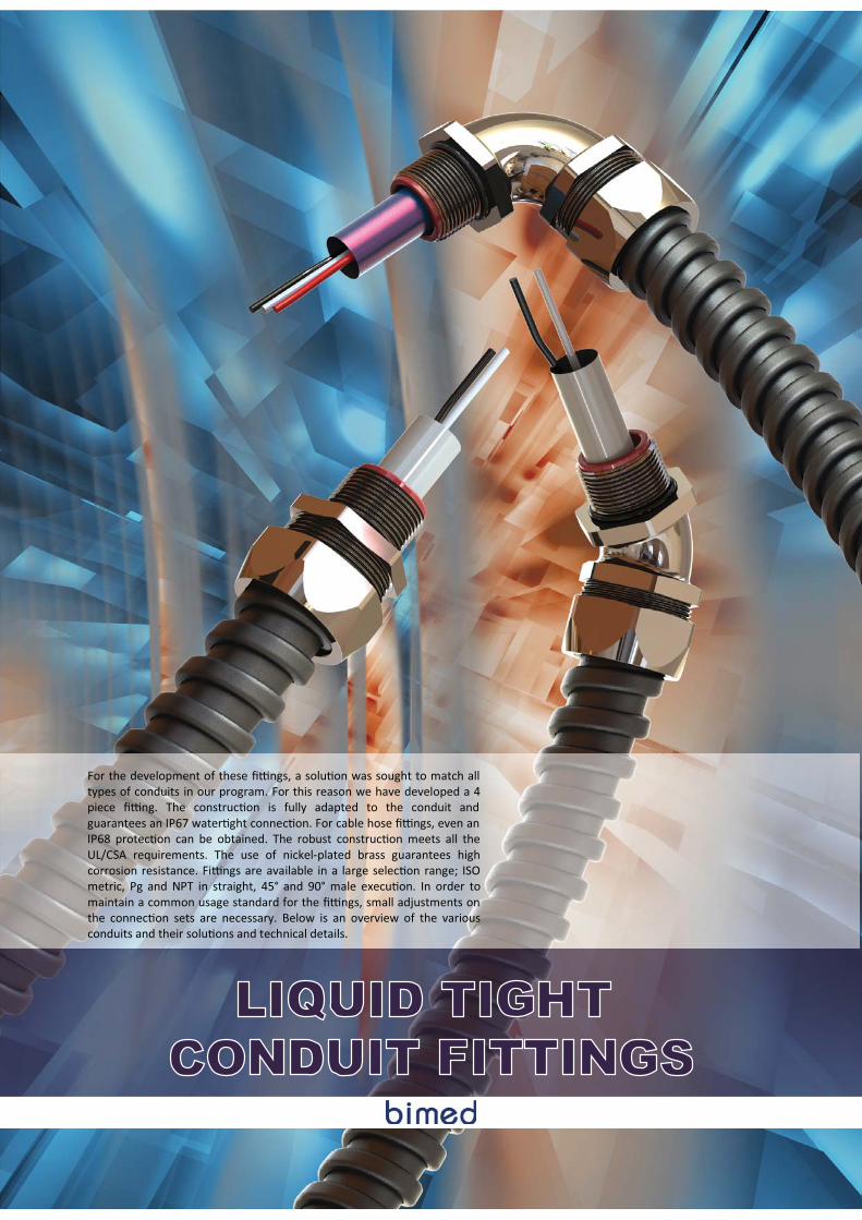
LIQUID TIGHT CONDUIT FITTINGS
For the development of these ��ngs, a solu�on was sought to match all types of conduits in our program. For this reason we have developed a 4 piece ��ng. The construc�on is fully adapted to the conduit and guarantees an IP67 water�ght connec�on. For cable hose ��ngs, even an IP68 protec�on can be obtained. The robust construc�on meets all the UL/CSA requirements. The use of nickel-plated brass guarantees high corrosion resistance. Fi�ngs are available in a large selec�on range; ISO metric, Pg and NPT in straight, 45° and 90° male execu�on. In order to maintain a common usage standard for the ��ngs, small adjustments on the connec�on sets are necessary. Below is an overview of the various conduits and their solu�ons and technical details.
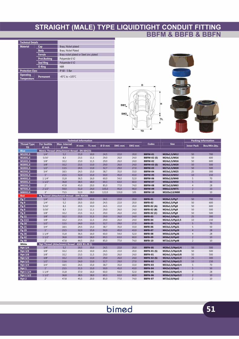
STRAIGHT (MALE) TYPE LIQUIDTIGHT CONDUIT FITTINGBBFM & BBFB & BBFN
51
Technical Details Material Cap Brass, Nickel plated
Body Brass, Nickel Plated Ferrule Brass nickel plated or Steel zinc plated Prot.Bushing Polyamide 6 V2 Seal Ring Polyamide 6 V2 O-Ring NBR
Protection Class IP 68 - 5 Bar Operating Temperature
Permanent -45°C to +105°C
TD
SW1 H
SW2
D
TL
Technical Information Codes Size
Packing Information Thread Type
TD For Sealtite
Ø inch Max. Internal
Ø mm H mm TL mm Ø D mm SW1 mm SW2 mm Inner Pack Box/Min.Qty.
Blue Metric Thread (Attachment thread : EN 60423) M12X1,5 1/4" 5,2 21,0 10,0 24,5 22,0 20,0 BBFM-01 M20x1,5/M12 50 700 M16X1,5 5/16" 8,3 23,5 11,5 29,0 26,0 24,0 BBFM-02 (S) M24x1,5/M16 50 600 M16X1,5 3/8" 10,2 23,0 11,5 29,0 26,0 24,0 BBFM-02 M24x1,5/M16 50 600 M20X1,5 3/8" 10,2 23,5 13,0 29,0 26,0 24,0 BBFM-03 (S) M24x1,5/M20 50 500 M20X1,5 1/2" 13,5 24,5 13,0 32,7 29,0 27,0 BBFM-03 M27x1,5/M20 50 500 M25X1,5 3/4" 18,5 24,5 15,0 38,7 35,0 33,0 BBFM-04 M33x1,5/M25 25 300 M32X1,5 1" 23,5 32,0 15,0 50,0 45,0 43,0 BBFM-05 M42x2,0/M32 10 150 M40X1,5 1 1/4" 31,8 36,5 16,0 60,0 54,0 52,0 BBFM-06 M50x2,0/M40 5 70 M50X1,5 1 1/2" 36,8 38,5 18,0 69,3 63,0 60,0 BBFM-07 M58x2,0/M50 5 50 M63X1,5 2" 47,8 45,0 20,0 85,0 77,0 74,0 BBFM-08 M72x2,0/M63 4 28 M75X1,5 2 1/2" 59,0 51,0 24,0 105,0 95,0 90,0 BBFM-09 M86x2,0/M75 2 10 M80X2,0 3" 73,5 52,0 28,0 122,0 110,0 105 BBFM-10 M103x2,0/M80 2 10 Red Pg Thread (Attachment thread : DIN 40430) Pg 7 1/4" 5,2 20,5 10,0 24,5 22,0 20,0 BBFB-01 M20x1,5/Pg7 50 700 Pg 9 1/4" 5,2 20,5 10,0 24,5 22,0 20,0 BBFB-02 M20x1,5/Pg9 50 600 Pg 9 5/16" 8,3 20,5 10,0 24,5 22,0 20,0 BBFB-02 (A) M20x1,5/Pg9 50 600 Pg 9 5/16" 8,3 23,5 11,5 29,0 26,0 24,0 BBFB-02 (B) M24x1,5/Pg9 50 500 Pg 9 3/8" 10,2 23,5 11,5 29,0 26,0 24,0 BBFB-02 (C) M24x1,5/Pg9 50 500 Pg 11 3/8" 10,2 23,5 11,5 29,0 26,0 24,0 BBFB-03 M24x1,5/Pg11 25 300 Pg 13,5 3/8" 10,2 23,5 11,5 29,0 26,0 24,0 BBFB-04 M24x1,5/Pg13,5 10 150 Pg 16 1/2" 13,5 24,0 13,0 32,7 29,0 27,0 BBFB-05 M27x1,5/Pg16 5 70 Pg 21 3/4" 18,5 24,5 15,0 38,7 35,0 33,0 BBFB-06 M33x1,5/Pg21 5 50 Pg 29 1" 23,5 32,0 15,0 50,0 45,0 43,0 BBFB-07 M42x2,0/Pg29 4 28 Pg 36 1 1/4" 31,8 36,5 16,0 60,0 54,0 52,0 BBFB-08 M50x2,0/Pg36 4 28 Pg 42 1 1/2" 36,8 39,0 18,0 69,3 63,0 60,0 BBFB-09 M58x2,0/Pg42 2 10 Pg 48 2" 47,8 44,5 20,0 85,0 77,0 74,0 BBFB-10 M72x2,0/Pg48 2 10 White Npt Thread (Attachment thread : ANSI B1.20.1) Npt 1/4 1/4" 5,2 20,5 10,0 24,5 22,0 20,0 BBFN-0S M20x1,5/Npt1/4 50 500 Npt 3/8 3/8" 10,2 23,5 10,0 24,5 22,0 20,0 BBFN-01 (S) M20x1,5/Npt3/8 50 500 Npt 3/8 3/8" 10,2 23,5 11,5 29,0 26,0 24,0 BBFN-01 M24x1,5/Npt3/8 50 500 Npt 1/2 3/8" 10,2 23,5 13,0 29,0 26,0 24,0 BBFN-02 (S) M24x1,5/Npt1/2 25 300 Npt 1/2 1/2" 13,6 24,0 13,0 32,7 29,0 27,0 BBFN-02 M27x1,5/Npt1/2 10 150 Npt 3/4 3/4" 18,5 24,5 15,0 38,7 35,0 33,0 BBFN-03 M33x1,5/Npt3/4 5 70 Npt 1 1" 23,5 31,5 15,0 50,0 45,0 43,0 BBFN-04 M42x2,0/Npt1 5 50 Npt 1 1/4 1 1/4" 31,8 37,0 16,0 60,0 54,0 52,0 BBFN-05 M50x2,0/Npt5/4 4 28 Npt 1 1/2 1 1/2" 36,8 38,5 18,0 69,3 63,0 60,0 BBFN-06 M58x2,0/Npt3/2 2 10 Npt 2 2" 47,8 45,5 20,0 85,0 77,0 74,0 BBFN-07 M72x2,0/Npt2 2 10
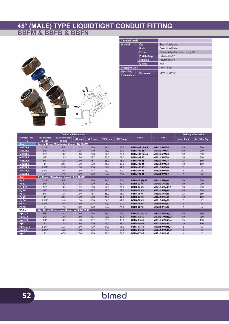
45° (MALE) TYPE LIQUIDTIGHT CONDUIT FITTINGBBFM & BBFB & BBFN
Technical Details Material Cap Brass, Nickel plated
Body Brass, Nickel Plated Ferrule Brass nickel plated or Steel zinc plated Prot.Bushing Polyamide 6 V2 Seal Ring Polyamide 6 V2 O-Ring NBR
Protection Class IP 68 - 5 Bar Operating Temperature
Permanent -45°C to +105°C
52
TL
SW2
SW1
D
SW2
TD
Technical Information Codes Size
Packing Information Thread Type
TD For Sealtite
Ø inch Max. Internal
Ø mm TL mm Ø D mm SW1 mm SW2 mm Inner Pack Box/Min.Qty.
Blue Metric Thread (Attachment thread : EN 60423) M16X1,5 5/16" 8,3 11,5 29,0 26,0 22,0 BBFM-02 (S) 45 M24x1,5/M16 50 300 M16X1,5 3/8" 10,2 11,5 29,0 26,0 22,0 BBFM-02 45 M24x1,5/M16 50 300 M20X1,5 3/8" 10,2 13,0 29,0 26,0 22,0 BBFM-03 (S) 45 M24x1,5/M20 50 250 M20X1,5 1/2" 13,5 13,0 32,7 29,0 27,0 BBFM-03 45 M27x1,5/M20 50 250 M25X1,5 3/4" 18,5 15,0 38,7 35,0 33,0 BBFM-04 45 M33x1,5/M25 25 150 M32X1,5 1" 23,5 15,0 50,0 45,0 42,0 BBFM-05 45 M42x2,0/M32 10 100 M40X1,5 1 1/4" 31,8 16,0 60,0 54,0 51,0 BBFM-06 45 M50x2,0/M40 5 50 M50X1,5 1 1/2" 36,8 18,0 69,3 63,0 60,0 BBFM-07 45 M58x2,0/M50 5 25 M63X1,5 2" 47,8 20,0 85,0 77,0 74,0 BBFM-08 45 M72x2,0/M63 4 16 Red Pg Thread (Attachment thread : DIN 40430) Pg 11 5/16" 8,3 11,5 29,0 26,0 22,0 BBFB-03 (S) 45 M24x1,5/Pg11 50 250 Pg 11 3/8" 10,2 11,5 29,0 26,0 22,0 BBFB-03 45 M24x1,5/Pg11 50 250 Pg 13,5 3/8" 10,2 11,5 29,0 26,0 22,0 BBFB-04 45 M24x1,5/Pg13,5 50 250 Pg 16 1/2" 13,5 13,0 32,7 29,0 27,0 BBFB-05 45 M27x1,5/Pg16 50 250 Pg 21 3/4" 18,5 15,0 38,7 35,0 33,0 BBFB-06 45 M33x1,5/Pg21 25 150 Pg 29 1" 23,5 15,0 50,0 45,0 42,0 BBFB-07 45 M42x2,0/Pg29 10 100 Pg 36 1 1/4" 31,8 16,0 60,0 54,0 51,0 BBFB-08 45 M50x2,0/Pg36 5 50 Pg 42 1 1/2" 36,8 18,0 69,3 63,0 60,0 BBFB-09 45 M58x2,0/Pg42 5 25 Pg 48 2" 47,8 20,0 85,0 77,0 74,0 BBFB-10 45 M72x2,0/Pg48 4 16 White Npt Thread (Attachment thread : ANSI B1.20.1) Npt 1/2 3/8" 10,2 13,0 29,0 26,0 22,0 BBFN-02 (S) 45 M24x1,5/Npt1/2 50 300 Npt 1/2 1/2" 13,5 13,0 32,7 29,0 27,0 BBFN-02 45 M27x1,5/Npt1/2 50 250 Npt 3/4 3/4" 18,5 15,0 38,7 35,0 33,0 BBFN-03 45 M33x1,5/Npt3/4 25 150 Npt 1 1" 23,5 15,0 50,0 45,0 42,0 BBFN-04 45 M42x2,0/Npt1 10 100 Npt 1 1/4 1 1/4" 31,8 16,0 60,0 54,0 51,0 BBFN-05 45 M50x2,0/Npt5/4 5 50 Npt 1 1/ 1 1/2" 36,8 18,0 69,3 63,0 60,0 BBFN-06 45 M58x2,0/Npt3/2 5 25 Npt 2 2" 47,8 20,0 85,0 77,0 74,0 BBFN-07 45 M72x2,0/Npt2 4 16
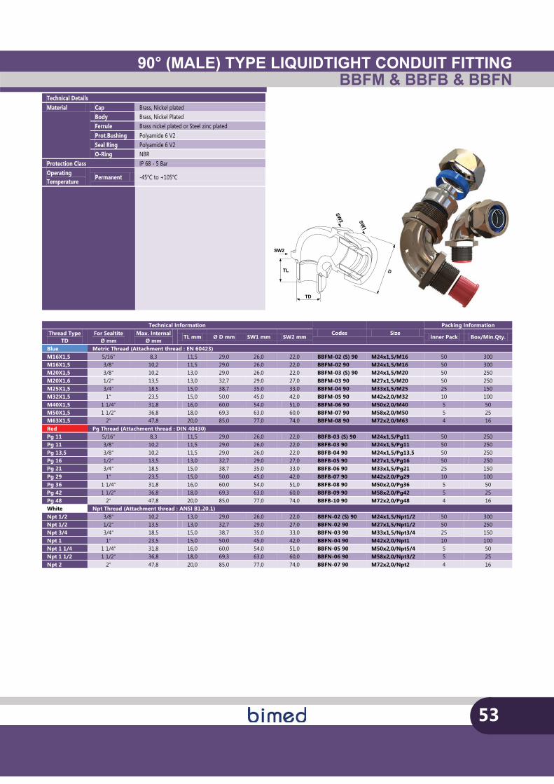
90° (MALE) TYPE LIQUIDTIGHT CONDUIT FITTINGBBFM & BBFB & BBFN
Technical Details Material Cap Brass, Nickel plated
Body Brass, Nickel Plated Ferrule Brass nickel plated or Steel zinc plated Prot.Bushing Polyamide 6 V2 Seal Ring Polyamide 6 V2 O-Ring NBR
Protection Class IP 68 - 5 Bar Operating Temperature
Permanent -45°C to +105°C
53
TL
SW2
SW1
D
SW2
TD
Technical Information Codes Size
Packing Information Thread Type
TD For Sealtite
Ø mm Max. Internal
Ø mm TL mm Ø D mm SW1 mm SW2 mm Inner Pack Box/Min.Qty.
Blue Metric Thread (Attachment thread : EN 60423) M16X1,5 5/16" 8,3 11,5 29,0 26,0 22,0 BBFM-02 (S) 90 M24x1,5/M16 50 300 M16X1,5 3/8" 10,2 11,5 29,0 26,0 22,0 BBFM-02 90 M24x1,5/M16 50 300 M20X1,5 3/8" 10,2 13,0 29,0 26,0 22,0 BBFM-03 (S) 90 M24x1,5/M20 50 250 M20X1,6 1/2" 13,5 13,0 32,7 29,0 27,0 BBFM-03 90 M27x1,5/M20 50 250 M25X1,5 3/4" 18,5 15,0 38,7 35,0 33,0 BBFM-04 90 M33x1,5/M25 25 150 M32X1,5 1" 23,5 15,0 50,0 45,0 42,0 BBFM-05 90 M42x2,0/M32 10 100 M40X1,5 1 1/4" 31,8 16,0 60,0 54,0 51,0 BBFM-06 90 M50x2,0/M40 5 50 M50X1,5 1 1/2" 36,8 18,0 69,3 63,0 60,0 BBFM-07 90 M58x2,0/M50 5 25 M63X1,5 2" 47,8 20,0 85,0 77,0 74,0 BBFM-08 90 M72x2,0/M63 4 16 Red Pg Thread (Attachment thread : DIN 40430) Pg 11 5/16" 8,3 11,5 29,0 26,0 22,0 BBFB-03 (S) 90 M24x1,5/Pg11 50 250 Pg 11 3/8" 10,2 11,5 29,0 26,0 22,0 BBFB-03 90 M24x1,5/Pg11 50 250 Pg 13,5 3/8" 10,2 11,5 29,0 26,0 22,0 BBFB-04 90 M24x1,5/Pg13,5 50 250 Pg 16 1/2" 13,5 13,0 32,7 29,0 27,0 BBFB-05 90 M27x1,5/Pg16 50 250 Pg 21 3/4" 18,5 15,0 38,7 35,0 33,0 BBFB-06 90 M33x1,5/Pg21 25 150 Pg 29 1" 23,5 15,0 50,0 45,0 42,0 BBFB-07 90 M42x2,0/Pg29 10 100 Pg 36 1 1/4" 31,8 16,0 60,0 54,0 51,0 BBFB-08 90 M50x2,0/Pg36 5 50 Pg 42 1 1/2" 36,8 18,0 69,3 63,0 60,0 BBFB-09 90 M58x2,0/Pg42 5 25 Pg 48 2" 47,8 20,0 85,0 77,0 74,0 BBFB-10 90 M72x2,0/Pg48 4 16 White Npt Thread (Attachment thread : ANSI B1.20.1) Npt 1/2 3/8" 10,2 13,0 29,0 26,0 22,0 BBFN-02 (S) 90 M24x1,5/Npt1/2 50 300 Npt 1/2 1/2" 13,5 13,0 32,7 29,0 27,0 BBFN-02 90 M27x1,5/Npt1/2 50 250 Npt 3/4 3/4" 18,5 15,0 38,7 35,0 33,0 BBFN-03 90 M33x1,5/Npt3/4 25 150 Npt 1 1" 23,5 15,0 50,0 45,0 42,0 BBFN-04 90 M42x2,0/Npt1 10 100 Npt 1 1/4 1 1/4" 31,8 16,0 60,0 54,0 51,0 BBFN-05 90 M50x2,0/Npt5/4 5 50 Npt 1 1/2 1 1/2" 36,8 18,0 69,3 63,0 60,0 BBFN-06 90 M58x2,0/Npt3/2 5 25 Npt 2 2" 47,8 20,0 85,0 77,0 74,0 BBFN-07 90 M72x2,0/Npt2 4 16
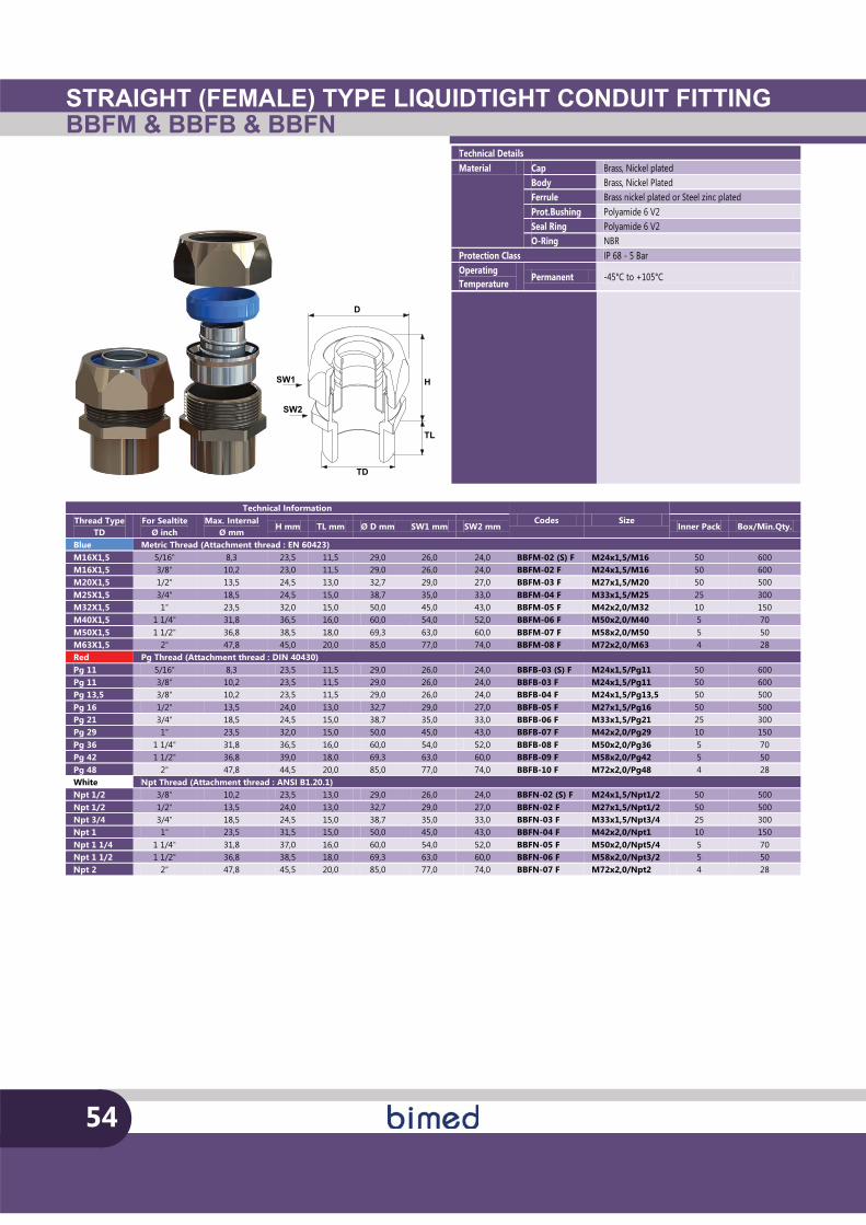
STRAIGHT (FEMALE) TYPE LIQUIDTIGHT CONDUIT FITTINGBBFM & BBFB & BBFN
54
Technical Details Material Cap Brass, Nickel plated
Body Brass, Nickel Plated Ferrule Brass nickel plated or Steel zinc plated Prot.Bushing Polyamide 6 V2 Seal Ring Polyamide 6 V2 O-Ring NBR
Protection Class IP 68 - 5 Bar Operating Temperature
Permanent -45°C to +105°C
TD
SW1 H
SW2
D
TL
Technical Information Codes Size
Thread Type
TD For Sealtite
Ø inch Max. Internal
Ø mm H mm TL mm Ø D mm SW1 mm SW2 mm Inner Pack Box/Min.Qty.
Blue Metric Thread (Attachment thread : EN 60423) M16X1,5 5/16" 8,3 23,5 11,5 29,0 26,0 24,0 BBFM-02 (S) F M24x1,5/M16 50 600 M16X1,5 3/8" 10,2 23,0 11,5 29,0 26,0 24,0 BBFM-02 F M24x1,5/M16 50 600 M20X1,5 1/2" 13,5 24,5 13,0 32,7 29,0 27,0 BBFM-03 F M27x1,5/M20 50 500 M25X1,5 3/4" 18,5 24,5 15,0 38,7 35,0 33,0 BBFM-04 F M33x1,5/M25 25 300 M32X1,5 1" 23,5 32,0 15,0 50,0 45,0 43,0 BBFM-05 F M42x2,0/M32 10 150 M40X1,5 1 1/4" 31,8 36,5 16,0 60,0 54,0 52,0 BBFM-06 F M50x2,0/M40 5 70 M50X1,5 1 1/2" 36,8 38,5 18,0 69,3 63,0 60,0 BBFM-07 F M58x2,0/M50 5 50 M63X1,5 2" 47,8 45,0 20,0 85,0 77,0 74,0 BBFM-08 F M72x2,0/M63 4 28 Red Pg Thread (Attachment thread : DIN 40430) Pg 11 5/16" 8,3 23,5 11,5 29,0 26,0 24,0 BBFB-03 (S) F M24x1,5/Pg11 50 600 Pg 11 3/8" 10,2 23,5 11,5 29,0 26,0 24,0 BBFB-03 F M24x1,5/Pg11 50 600 Pg 13,5 3/8" 10,2 23,5 11,5 29,0 26,0 24,0 BBFB-04 F M24x1,5/Pg13,5 50 500 Pg 16 1/2" 13,5 24,0 13,0 32,7 29,0 27,0 BBFB-05 F M27x1,5/Pg16 50 500 Pg 21 3/4" 18,5 24,5 15,0 38,7 35,0 33,0 BBFB-06 F M33x1,5/Pg21 25 300 Pg 29 1" 23,5 32,0 15,0 50,0 45,0 43,0 BBFB-07 F M42x2,0/Pg29 10 150 Pg 36 1 1/4" 31,8 36,5 16,0 60,0 54,0 52,0 BBFB-08 F M50x2,0/Pg36 5 70 Pg 42 1 1/2" 36,8 39,0 18,0 69,3 63,0 60,0 BBFB-09 F M58x2,0/Pg42 5 50 Pg 48 2" 47,8 44,5 20,0 85,0 77,0 74,0 BBFB-10 F M72x2,0/Pg48 4 28 White Npt Thread (Attachment thread : ANSI B1.20.1) Npt 1/2 3/8" 10,2 23,5 13,0 29,0 26,0 24,0 BBFN-02 (S) F M24x1,5/Npt1/2 50 500 Npt 1/2 1/2" 13,5 24,0 13,0 32,7 29,0 27,0 BBFN-02 F M27x1,5/Npt1/2 50 500 Npt 3/4 3/4" 18,5 24,5 15,0 38,7 35,0 33,0 BBFN-03 F M33x1,5/Npt3/4 25 300 Npt 1 1" 23,5 31,5 15,0 50,0 45,0 43,0 BBFN-04 F M42x2,0/Npt1 10 150 Npt 1 1/4 1 1/4" 31,8 37,0 16,0 60,0 54,0 52,0 BBFN-05 F M50x2,0/Npt5/4 5 70 Npt 1 1/2 1 1/2" 36,8 38,5 18,0 69,3 63,0 60,0 BBFN-06 F M58x2,0/Npt3/2 5 50 Npt 2 2" 47,8 45,5 20,0 85,0 77,0 74,0 BBFN-07 F M72x2,0/Npt2 4 28
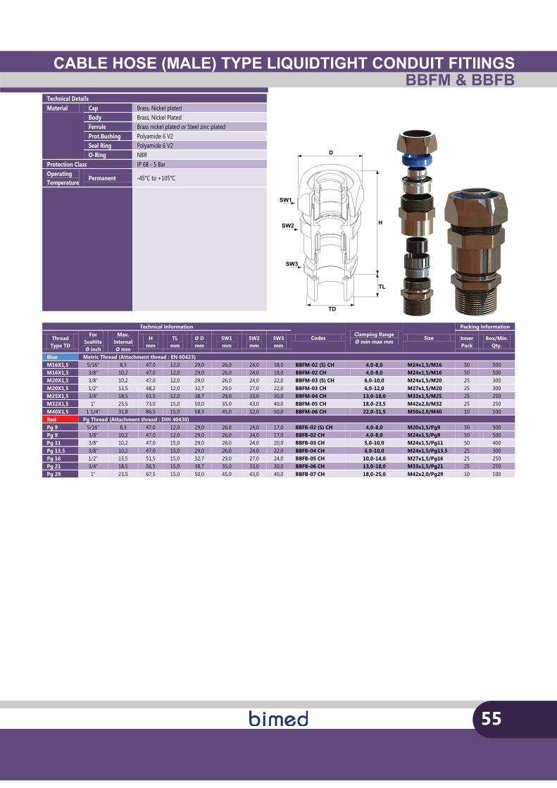
CABLE HOSE (MALE) TYPE LIQUIDTIGHT CONDUIT FITIINGSBBFM & BBFB
Technical Details Material Cap Brass, Nickel plated
Body Brass, Nickel Plated Ferrule Brass nickel plated or Steel zinc plated Prot.Bushing Polyamide 6 V2 Seal Ring Polyamide 6 V2 O-Ring NBR
Protection Class IP 68 - 5 Bar Operating Temperature
Permanent -45°C to +105°C
55
TD
SW1
H
SW3
D
TL
SW2
Technical Information
Codes Clamping Range Ø min-max mm
Size
Packing Information
Thread Type TD
For Sealtite Ø inch
Max. Internal Ø mm
H mm
TL mm
Ø D mm
SW1 mm
SW2 mm
SW3 mm
Inner Pack
Box/Min. Qty.
Blue Metric Thread (Attachment thread : EN 60423) M16X1,5 5/16" 8,3 47,0 12,0 29,0 26,0 24,0 18,0 BBFM-02 (S) CH 4,0-8,0 M24x1,5/M16 50 500 M16X1,5 3/8" 10,2 47,0 12,0 29,0 26,0 24,0 18,0 BBFM-02 CH 4,0-8,0 M24x1,5/M16 50 500 M20X1,5 3/8" 10,2 47,0 12,0 29,0 26,0 24,0 22,0 BBFM-03 (S) CH 6,0-10,0 M24x1,5/M20 25 300 M20X1,5 1/2" 13,5 48,2 12,0 32,7 29,0 27,0 22,0 BBFM-03 CH 6,0-12,0 M27x1,5/M20 25 300 M25X1,5 3/4" 18,5 61,5 12,0 38,7 29,0 33,0 30,0 BBFM-04 CH 13,0-18,0 M33x1,5/M25 25 250 M32X1,5 1" 23,5 73,0 15,0 50,0 35,0 43,0 40,0 BBFM-05 CH 18,0-23,5 M42x2,0/M32 25 250 M40X1,5 1 1/4" 31,8 86,5 15,0 58,3 45,0 52,0 50,0 BBFM-06 CH 22,0-31,5 M50x2,0/M40 10 100 Red Pg Thread (Attachment thread : DIN 40430) Pg 9 5/16" 8,3 47,0 12,0 29,0 26,0 24,0 17,0 BBFB-02 (S) CH 4,0-8,0 M20x1,5/Pg9 50 500 Pg 9 3/8" 10,2 47,0 12,0 29,0 26,0 24,0 17,0 BBFB-02 CH 4,0-8,0 M24x1,5/Pg9 50 500 Pg 11 3/8" 10,2 47,0 15,0 29,0 26,0 24,0 20,0 BBFB-03 CH 5,0-10,0 M24x1,5/Pg11 50 400 Pg 13,5 3/8" 10,2 47,0 15,0 29,0 26,0 24,0 22,0 BBFB-04 CH 6,0-10,0 M24x1,5/Pg13,5 25 300 Pg 16 1/2" 13,5 51,5 15,0 32,7 29,0 27,0 24,0 BBFB-05 CH 10,0-14,0 M27x1,5/Pg16 25 250 Pg 21 3/4" 18,5 56,5 15,0 38,7 35,0 33,0 30,0 BBFB-06 CH 13,0-18,0 M33x1,5/Pg21 25 250 Pg 29 1" 23,5 67,5 15,0 50,0 45,0 43,0 40,0 BBFB-07 CH 18,0-25,0 M42x2,0/Pg29 10 100
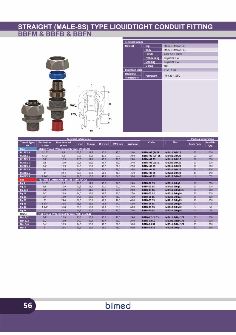
STRAIGHT (MALE-SS) TYPE LIQUIDTIGHT CONDUIT FITTINGBBFM & BBFB & BBFN
56
TD
SW1 H
SW2
D
TL
Technical Details Material Cap Stainless Steel AISI 303
Body Stainless Steel AISI 303 Ferrule Brass nickel plated Prot.Bushing Polyamide 6 V2 Seal Ring Polyamide 6 V2 O-Ring NBR
Protection Class IP 68 - 5 Bar Operating Temperature
Permanent -45°C to +105°C
Technical Information Codes Size
Packing Information Thread Type
TD For Sealtite
Ø inch Max. Internal
Ø mm H mm TL mm Ø D mm SW1 mm SW2 mm Inner Pack
Box/Min. Qty.
Blue Metric Thread (Attachment thread : EN 60423) M16X1,5 5/16" 8,3 23,5 11,5 30,0 27,0 24,0 BBFM-02 (S) SS M24x1,5/M16 50 600 M20X1,5 5/16" 8,3 23,5 13,0 30,0 27,0 24,0 BBFM-03 (SP) SS M24x1,5/M20 50 500 M16X1,5 3/8" 10,9 23,0 11,5 30,0 27,0 24,0 BBFM-02 SS M24x1,5/M16 50 600 M20X1,5 3/8" 10,9 23,5 13,0 33,7 30,0 27,0 BBFM-03 (S) SS M27x1,5/M20 50 500 M20X1,5 1/2" 13,9 24,5 13,0 33,7 30,0 27,0 BBFM-03 SS M27x1,5/M20 50 500 M25X1,5 3/4" 18,9 24,5 15,0 39,7 36,0 36,0 BBFM-04 SS M33x1,5/M25 25 300 M32X1,5 1" 24,4 32,0 15,0 51,0 46,0 46,0 BBFM-05 SS M42x2,0/M32 10 150 M40X1,5 1 1/4" 31,8 36,5 16,0 58,3 54,0 52,0 BBFM-06 SS M50x2,0/M40 5 70 Red Pg Thread (Attachment thread : DIN 40430) Pg 9 5/16" 8,3 20,5 11,5 30,0 26,0 24,0 BBFB-02 SS M20x1,5/Pg9 50 600 Pg 11 3/8" 10,9 23,5 11,5 30,0 27,0 24,0 BBFB-03 SS M24x1,5/Pg11 50 600 Pg 13,5 3/8" 10,9 23,5 11,5 30,0 27,0 24,0 BBFB-04 SS M24x1,5/Pg13,5 50 500 Pg 16 1/2" 13,9 24,0 13,0 33,7 30,0 27,0 BBFB-05 SS M27x1,5/Pg16 50 500 Pg 21 3/4" 18,9 24,5 15,0 39,7 36,0 36,0 BBFB-06 SS M33x1,5/Pg21 25 300 Pg 29 1" 24,4 32,0 15,0 51,0 46,0 46,0 BBFB-07 SS M42x2,0/Pg29 10 150 Pg 36 1 1/4" 31,8 36,5 16,0 58,3 54,0 52,0 BBFB-08 SS M50x2,0/Pg36 5 70 Pg 42 1 1/2" 36,8 39,0 18,0 67,8 63,0 60,0 BBFB-09 SS M58x2,0/Pg42 5 50 Pg 48 2" 47,8 44,5 20,0 82,2 77,0 74,0 BBFB-10 SS M72x2,0/Pg48 4 28 White Npt Thread (Attachment thread : ANSI B1.20.1) Npt 1/2 3/8" 10,9 23,5 13,0 30,0 27,0 24,0 BBFN-02 (S) SS M24x1,5/Npt1/2 50 500 Npt 1/2 1/2" 13,9 24,0 13,0 33,7 30,0 27,0 BBFN-02 SS M27x1,5/Npt1/2 50 500 Npt 3/4 3/4" 18,9 24,5 15,0 39,7 36,0 36,0 BBFN-03 SS M33x1,5/Npt3/4 25 300 Npt 1 1" 24,4 31,5 15,0 51,0 46,0 46,0 BBFN-04 SS M42x2,0/Npt1 10 150
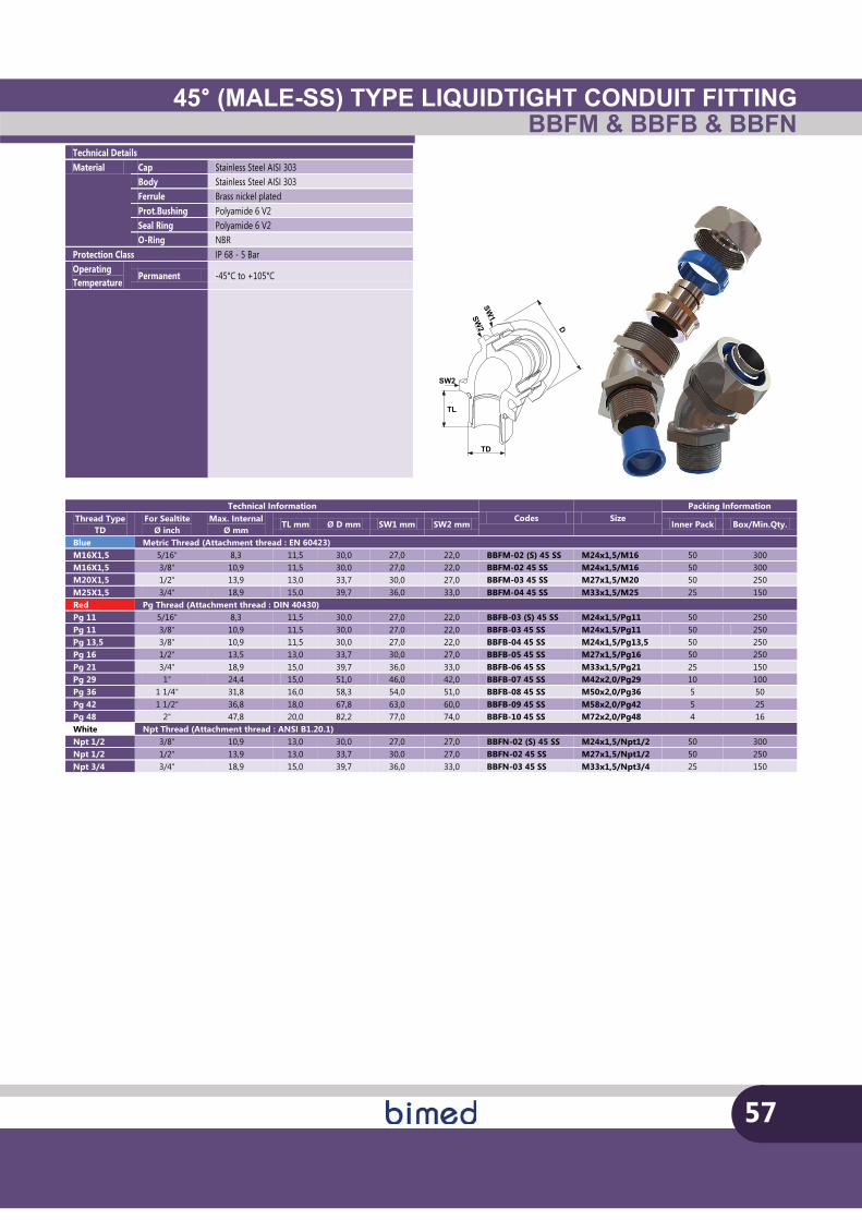
45° (MALE-SS) TYPE LIQUIDTIGHT CONDUIT FITTINGBBFM & BBFB & BBFN
57
TL
SW2SW
1
D
SW2
TD
Technical Details Material Cap Stainless Steel AISI 303
Body Stainless Steel AISI 303 Ferrule Brass nickel plated Prot.Bushing Polyamide 6 V2 Seal Ring Polyamide 6 V2 O-Ring NBR
Protection Class IP 68 - 5 Bar Operating Temperature
Permanent -45°C to +105°C
Technical Information Codes Size
Packing Information Thread Type
TD For Sealtite
Ø inch Max. Internal
Ø mm TL mm Ø D mm SW1 mm SW2 mm Inner Pack Box/Min.Qty.
Blue Metric Thread (Attachment thread : EN 60423) M16X1,5 5/16" 8,3 11,5 30,0 27,0 22,0 BBFM-02 (S) 45 SS M24x1,5/M16 50 300 M16X1,5 3/8" 10,9 11,5 30,0 27,0 22,0 BBFM-02 45 SS M24x1,5/M16 50 300 M20X1,5 1/2" 13,9 13,0 33,7 30,0 27,0 BBFM-03 45 SS M27x1,5/M20 50 250 M25X1,5 3/4" 18,9 15,0 39,7 36,0 33,0 BBFM-04 45 SS M33x1,5/M25 25 150 Red Pg Thread (Attachment thread : DIN 40430) Pg 11 5/16" 8,3 11,5 30,0 27,0 22,0 BBFB-03 (S) 45 SS M24x1,5/Pg11 50 250 Pg 11 3/8" 10,9 11,5 30,0 27,0 22,0 BBFB-03 45 SS M24x1,5/Pg11 50 250 Pg 13,5 3/8" 10,9 11,5 30,0 27,0 22,0 BBFB-04 45 SS M24x1,5/Pg13,5 50 250 Pg 16 1/2" 13,5 13,0 33,7 30,0 27,0 BBFB-05 45 SS M27x1,5/Pg16 50 250 Pg 21 3/4" 18,9 15,0 39,7 36,0 33,0 BBFB-06 45 SS M33x1,5/Pg21 25 150 Pg 29 1" 24,4 15,0 51,0 46,0 42,0 BBFB-07 45 SS M42x2,0/Pg29 10 100 Pg 36 1 1/4" 31,8 16,0 58,3 54,0 51,0 BBFB-08 45 SS M50x2,0/Pg36 5 50 Pg 42 1 1/2" 36,8 18,0 67,8 63,0 60,0 BBFB-09 45 SS M58x2,0/Pg42 5 25 Pg 48 2" 47,8 20,0 82,2 77,0 74,0 BBFB-10 45 SS M72x2,0/Pg48 4 16 White Npt Thread (Attachment thread : ANSI B1.20.1) Npt 1/2 3/8" 10,9 13,0 30,0 27,0 27,0 BBFN-02 (S) 45 SS M24x1,5/Npt1/2 50 300 Npt 1/2 1/2" 13,9 13,0 33,7 30,0 27,0 BBFN-02 45 SS M27x1,5/Npt1/2 50 250 Npt 3/4 3/4" 18,9 15,0 39,7 36,0 33,0 BBFN-03 45 SS M33x1,5/Npt3/4 25 150
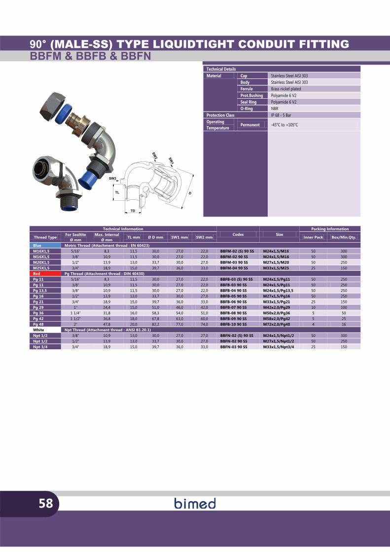
90° (MALE-SS) TYPE LIQUIDTIGHT CONDUIT FITTINGBBFM & BBFB & BBFN
58
TL
SW2
SW1
D
SW2
TD
Technical Details Material Cap Stainless Steel AISI 303
Body Stainless Steel AISI 303 Ferrule Brass nickel plated Prot.Bushing Polyamide 6 V2 Seal Ring Polyamide 6 V2 O-Ring NBR
Protection Class IP 68 - 5 Bar Operating Temperature
Permanent -45°C to +105°C
Technical Information Codes Size
Packing Information
Thread Type For Sealtite
Ø mm Max. Internal
Ø mm TL mm Ø D mm SW1 mm SW2 mm Inner Pack Box/Min.Qty.
Blue Metric Thread (Attachment thread : EN 60423) M16X1,5 5/16" 8,3 11,5 30,0 27,0 22,0 BBFM-02 (S) 90 SS M24x1,5/M16 50 300 M16X1,5 3/8" 10,9 11,5 30,0 27,0 22,0 BBFM-02 90 SS M24x1,5/M16 50 300 M20X1,5 1/2" 13,9 13,0 33,7 30,0 27,0 BBFM-03 90 SS M27x1,5/M20 50 250 M25X1,5 3/4" 18,9 15,0 39,7 36,0 33,0 BBFM-04 90 SS M33x1,5/M25 25 150 Red Pg Thread (Attachment thread : DIN 40430) Pg 11 5/16" 8,3 11,5 30,0 27,0 22,0 BBFB-03 (S) 90 SS M24x1,5/Pg11 50 250 Pg 11 3/8" 10,9 11,5 30,0 27,0 22,0 BBFB-03 90 SS M24x1,5/Pg11 50 250 Pg 13,5 3/8" 10,9 11,5 30,0 27,0 22,0 BBFB-04 90 SS M24x1,5/Pg13,5 50 250 Pg 16 1/2" 13,9 13,0 33,7 30,0 27,0 BBFB-05 90 SS M27x1,5/Pg16 50 250 Pg 21 3/4" 18,9 15,0 39,7 36,0 33,0 BBFB-06 90 SS M33x1,5/Pg21 25 150 Pg 29 1" 24,4 15,0 51,0 46,0 42,0 BBFB-07 90 SS M42x2,0/Pg29 10 100 Pg 36 1 1/4" 31,8 16,0 58,3 54,0 51,0 BBFB-08 90 SS M50x2,0/Pg36 5 50 Pg 42 1 1/2" 36,8 18,0 67,8 63,0 60,0 BBFB-09 90 SS M58x2,0/Pg42 5 25 Pg 48 2" 47,8 20,0 82,2 77,0 74,0 BBFB-10 90 SS M72x2,0/Pg48 4 16 White Npt Thread (Attachment thread : ANSI B1.20.1) Npt 1/2 3/8" 10,9 13,0 30,0 27,0 27,0 BBFN-02 (S) 90 SS M24x1,5/Npt1/2 50 300 Npt 1/2 1/2" 13,9 13,0 33,7 30,0 27,0 BBFN-02 90 SS M27x1,5/Npt1/2 50 250 Npt 3/4 3/4" 18,9 15,0 39,7 36,0 33,0 BBFN-03 90 SS M33x1,5/Npt3/4 25 150
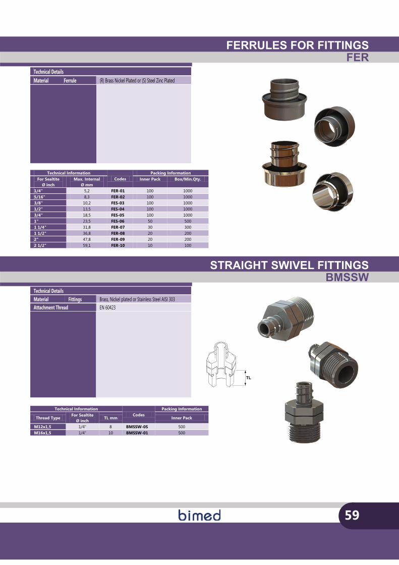
FERRULES FOR FITTINGSFER
STRAIGHT SWIVEL FITTINGSBMSSW
59
Technical Details Material Ferrule (R) Brass Nickel Plated or (S) Steel Zinc Plated
Technical Information Codes
Packing Information For Sealtite
Ø inch Max. Internal
Ø mm Inner Pack Box/Min.Qty.
1/4" 5,2 FER-01 100 1000 5/16" 8,3 FER-02 100 1000 3/8" 10,2 FES-03 100 1000 1/2" 13,5 FES-04 100 1000 3/4" 18,5 FES-05 100 1000 1" 23,5 FES-06 50 500 1 1/4" 31,8 FER-07 30 300 1 1/2" 36,8 FER-08 20 200 2" 47,8 FER-09 20 200 2 1/2" 59,1 FER-10 10 100
Technical Details Material Fittings Brass, Nickel plated or Stainless Steel AISI 303 Attachment Thread EN 60423
TL
Technical Information Codes
Packing Information
Thread Type For Sealtite
Ø inch TL mm Inner Pack
M12x1,5 1/4" 8 BMSSW-0S 500 M16x1,5 1/4" 10 BMSSW-01 500
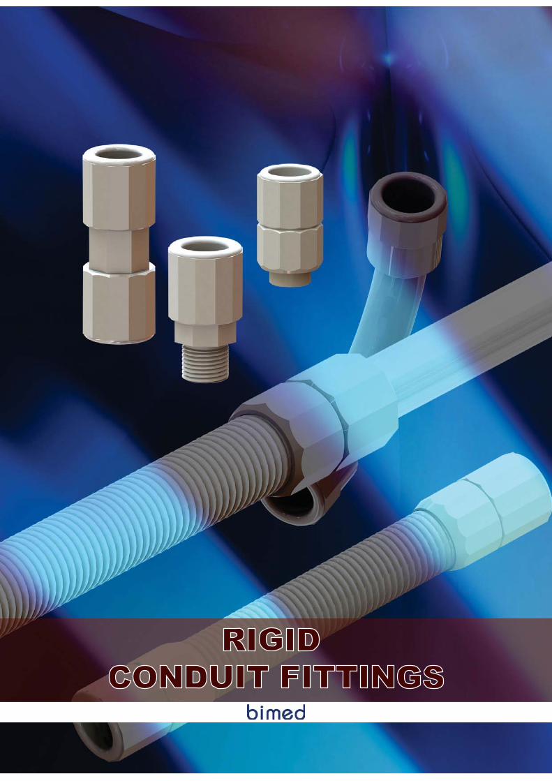
RIGID CONDUIT FITTINGS
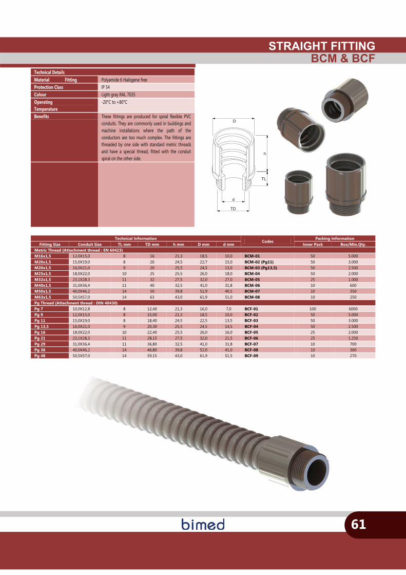
STRAIGHT FITTINGBCM & BCF
d
TL
D
h
TD
61
Technical Details Material Fitting Polyamide 6 Halogene free Protection Class IP 54 Colour Light gray RAL 7035 Operating Temperature
-20°C to +80°C
Benefits These fittings are produced for spiral flexible PVC conduits. They are commonly used in buildings and machine installations where the path of the conductors are too much complex. The fittings are threaded by one side with standard metric threads and have a special thread, fitted with the conduit spiral on the other side.
Technical Information Codes
Packing Information Fitting Size Conduit Size TL mm TD mm h mm D mm d mm Inner Pack Box/Min.Qty.
Metric Thread (Attachment thread : EN 60423) M16x1,5 12,0X15,0 8 16 21,3 18,5 10,0 BCM-01 50 5.000 M20x1,5 15,0X19,0 8 20 24,5 22,7 15,0 BCM-02 (Pg11) 50 3.000 M20x1,5 16,0X21,0 9 20 25,5 24,5 13,0 BCM-03 (Pg13,5) 50 2.500 M25x1,5 18,0X22,0 10 25 25,5 26,0 18,0 BCM-04 50 2.000 M32x1,5 23,1X28,3 11 32 27,5 32,0 27,0 BCM-05 25 1.000 M40x1,5 31,0X36,4 11 40 32,5 41,0 31,8 BCM-06 10 600 M50x1,5 40,0X46,2 14 50 39,8 51,9 40,5 BCM-07 10 350 M63x1,5 50,5X57,0 14 63 43,0 61,9 51,0 BCM-08 10 250 Pg Thread (Attachment thread : DIN 40430) Pg 7 10,0X12,8 8 12,40 21,3 16,0 7,0 BCF-01 100 6000 Pg 9 12,0X15,0 8 15,00 21,3 18,5 10,0 BCF-02 50 5.000 Pg 11 15,0X19,0 8 18,40 24,5 22,5 13,5 BCF-03 50 3.000 Pg 13,5 16,0X21,0 9 20,30 25,5 24,5 14,5 BCF-04 50 2.500 Pg 16 18,0X22,0 10 22,40 25,5 26,0 16,0 BCF-05 25 2.000 Pg 21 23,1X28,3 11 28,15 27,5 32,0 21,5 BCF-06 25 1.250 Pg 29 31,0X36,4 11 36,80 32,5 41,0 31,8 BCF-07 10 700 Pg 36 40,0X46,2 14 46,80 39,8 52,0 41,0 BCF-08 10 360 Pg 48 50,5X57,0 14 59,15 43,0 61,9 51,5 BCF-09 10 270
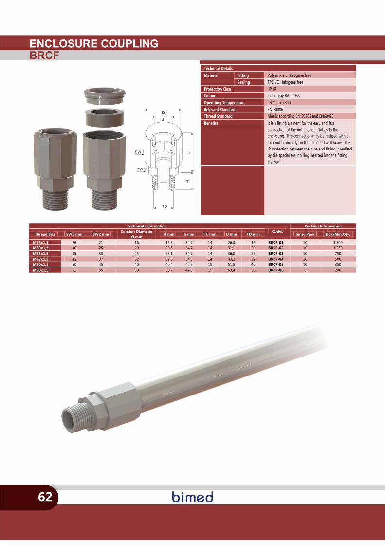
ENCLOSURE COUPLINGBRCF
SW 2
h
TL
TD
d
D
SW 1
62
Technical Details Material Fitting Polyamide 6 Halogene free
Sealing TPE VO Halogene free Protection Class IP 67 Colour Light gray RAL 7035 Operating Temperature -20°C to +80°C Relevant Standard EN 50086 Thread Standard Metric according EN 50262 and EN60423 Benefits It is a fitting element for the easy and fast
connection of the right conduit tubes to the enclosures. This connection may be realised with a lock nut or directly on the threaded wall boxes. The IP protection between the tube and fitting is realised by the special sealing ring inserted into the fitting element.
Technical Information Codes
Packing Information
Thread Size SW1 mm SW2 mm Conduit Diameter
Ø mm d mm h mm TL mm D mm TD mm Inner Pack Box/Min.Qty.
M16x1,5 26 21 16 16,5 34,7 14 26,3 16 BRCF-01 10 1.500 M20x1,5 30 25 20 20,5 34,7 14 31,1 20 BRCF-02 10 1.250 M25x1,5 35 30 25 25,1 34,7 14 36,0 25 BRCF-03 10 750 M32x1,5 42 37 32 32,6 34,5 14 43,2 32 BRCF-04 10 500 M40x1,5 50 45 40 40,4 42,5 19 51,5 40 BRCF-05 10 350 M50x1,5 62 55 50 50,7 42,5 19 63,4 50 BRCF-06 5 200
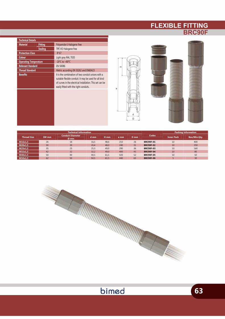
FLEXIBLE FITTINGBRC90F
63
a
D
dd
Technical Details Material Fitting Polyamide 6 Halogene free
Sealing TPE VO Halogene free Protection Class IP 67 Colour Light gray RAL 7035 Operating Temperature -20°C to +80°C Relevant Standard EN 50086 Thread Standard Metric according EN 50262 and EN60423 Benefits It is the combination of two conduit unions with a
suitable flexible conduit. It may be used for all kind of curves in the electrical installation. This set can be easily fitted with the right conduits.
Technical Information Codes
Packing Information
Thread Size SW mm Conduit Diameter
Ø mm d mm H mm a mm D mm Inner Pack Box/Min.Qty.
M16x1,5 26 16 16,5 48,6 210 26 BRC90F-01 10 400 M20x1,5 30 20 20,4 48,0 240 31 BRC90F-02 10 250 M25x1,5 35 25 25,3 49,0 290 36 BRC90F-03 10 160 M32x1,5 42 32 32,2 49,0 400 43 BRC90F-04 10 80 M40x1,5 50 40 40,5 61,5 420 52 BRC90F-05 10 50 M50x1,5 62 50 50,5 61,5 440 63 BRC90F-06 5 30
H
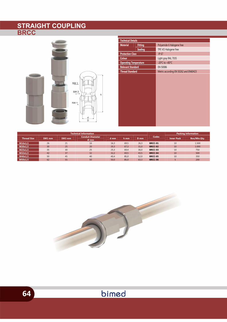
STRAIGHT COUPLINGBRCC
h
Dd
SW 1
SW 2
SW 1
64
SW 1
SW
SW 1
Technical Details Material Fitting Polyamide 6 Halogene free
Sealing TPE VO Halogene free Protection Class IP 67 Colour Light gray RAL 7035 Operating Temperature -20°C to +80°C Relevant Standard EN 50086 Thread Standard Metric according EN 50262 and EN60423
Technical Information Codes
Packing Information
Thread Size SW1 mm SW2 mm Conduit Diameter
Ø mm d mm h mm D mm Inner Pack Box/Min.Qty.
M16x1,5 26 21 16 16,3 69,5 26,3 BRCC-01 10 1.500 M20x1,5 30 25 20 20,3 67,3 31,0 BRCC-02 10 1.000 M25x1,5 35 30 25 25,3 69,4 36,0 BRCC-03 10 750 M32x1,5 42 37 32 32,2 69,5 43,5 BRCC-04 10 500 M40x1,5 50 45 40 40,4 85,0 52,0 BRCC-05 10 350 M50x1,5 62 55 50 50,0 85,0 63,3 BRCC-06 5 200
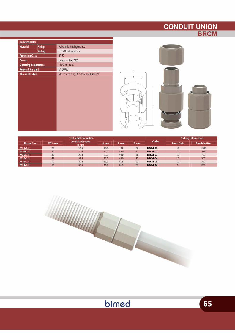
CONDUIT UNIONBRCM
h
D
d
65
Technical Details Material Fitting Polyamide 6 Halogene free
Sealing TPE VO Halogene free Protection Class IP 67 Colour Light gray RAL 7035 Operating Temperature -20°C to +80°C Relevant Standard EN 50086 Thread Standard Metric according EN 50262 and EN60423
Technical Information Codes
Packing Information
Thread Size SW1 mm Conduit Diameter
Ø mm d mm h mm D mm Inner Pack Box/Min.Qty.
M16x1,5 26 16,5 12,0 49,0 26 BRCM-01 10 1.500 M20x1,5 30 20,4 16,0 49,0 31 BRCM-02 10 1.000 M25x1,5 35 25,3 20,5 49,0 36 BRCM-03 10 750 M32x1,5 42 32,3 26,0 49,0 43 BRCM-04 10 500 M40x1,5 50 40,4 33,5 61,5 52 BRCM-05 10 350 M50x1,5 62 50,5 44,0 61,5 63 BRCM-06 5 200
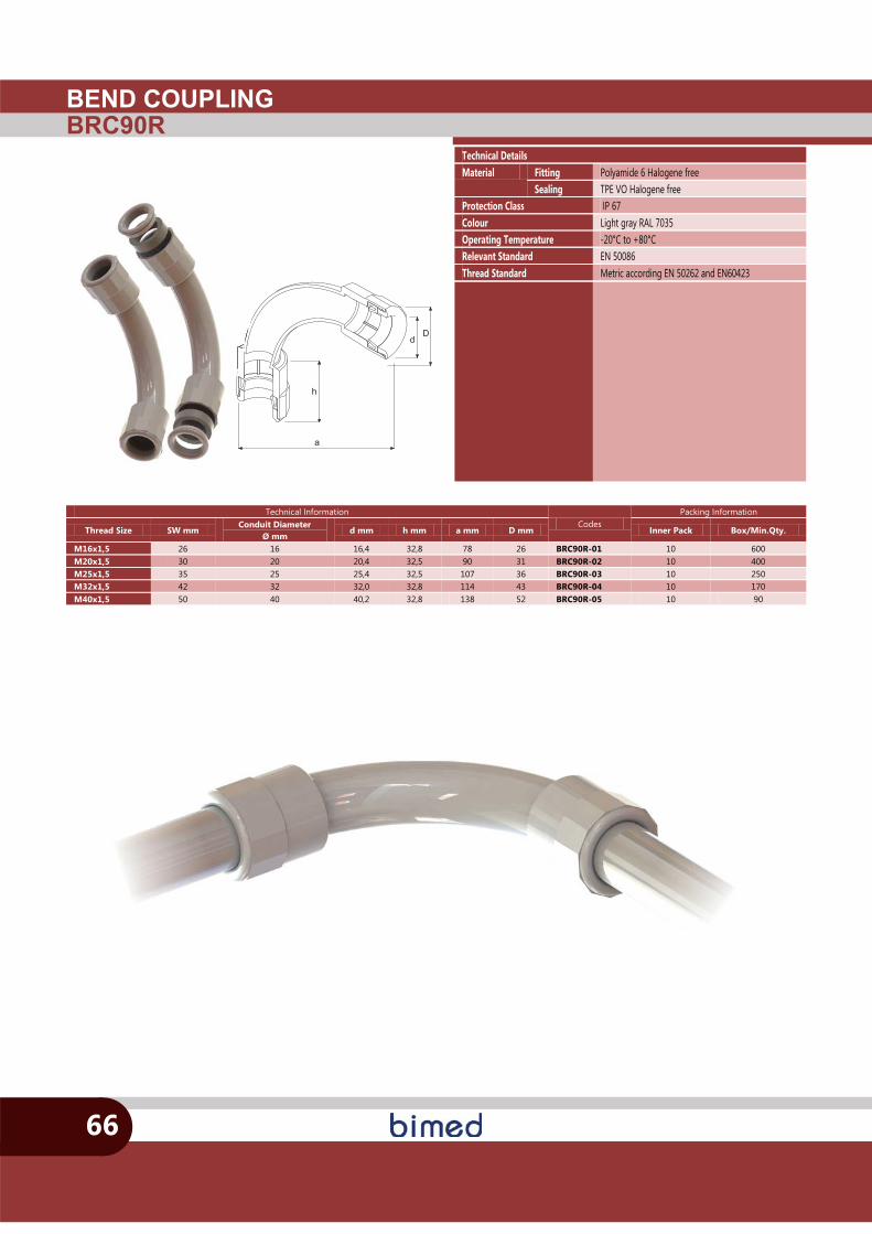
BEND COUPLINGBRC90R
h
a
Dd
66
Technical Details Material Fitting Polyamide 6 Halogene free
Sealing TPE VO Halogene free Protection Class IP 67 Colour Light gray RAL 7035 Operating Temperature -20°C to +80°C Relevant Standard EN 50086 Thread Standard Metric according EN 50262 and EN60423
Technical Information Codes
Packing Information
Thread Size SW mm Conduit Diameter
Ø mm d mm h mm a mm D mm Inner Pack Box/Min.Qty.
M16x1,5 26 16 16,4 32,8 78 26 BRC90R-01 10 600 M20x1,5 30 20 20,4 32,5 90 31 BRC90R-02 10 400 M25x1,5 35 25 25,4 32,5 107 36 BRC90R-03 10 250 M32x1,5 42 32 32,0 32,8 114 43 BRC90R-04 10 170 M40x1,5 50 40 40,2 32,8 138 52 BRC90R-05 10 90
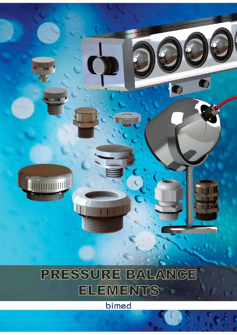
PRESSURE BALANCEELEMENTS
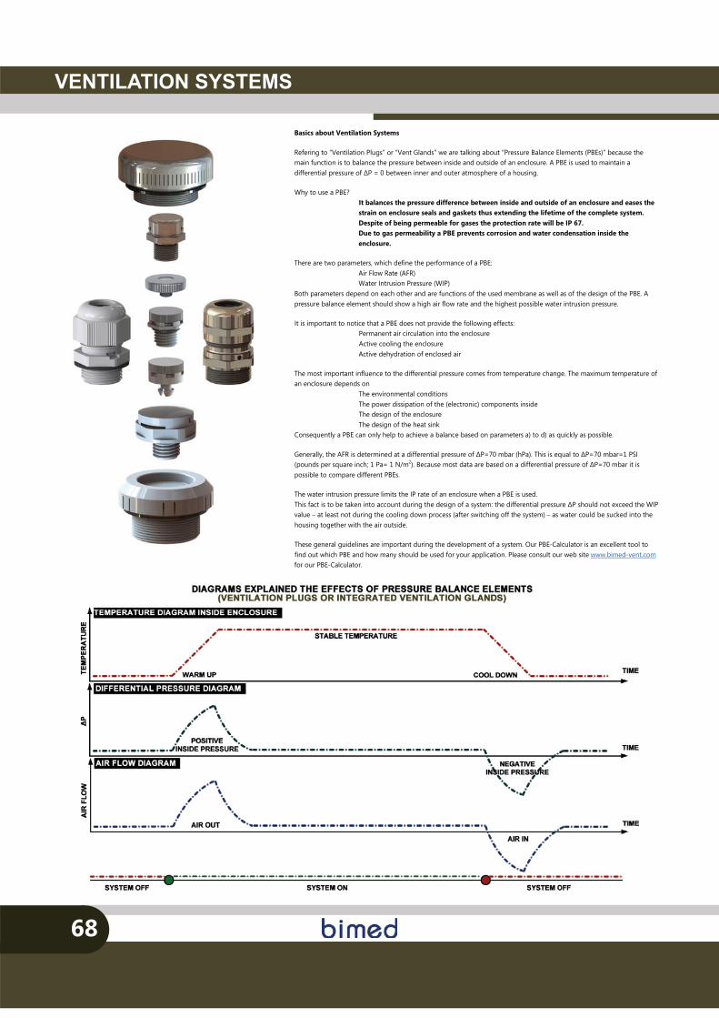
VENTILATION SYSTEMS
68
Basics about Ventilation Systems
Refering to “Ventilation Plugs” or “Vent Glands” we are talking about “Pressure Balance Elements (PBEs)” because the main function is to balance the pressure between inside and outside of an enclosure. A PBE is used to maintain a differential pressure of �P = 0 between inner and outer atmosphere of a housing.
Why to use a PBE? It balances the pressure difference between inside and outside of an enclosure and eases the strain on enclosure seals and gaskets thus extending the lifetime of the complete system. Despite of being permeable for gases the protection rate will be IP 67. Due to gas permeability a PBE prevents corrosion and water condensation inside the enclosure.
There are two parameters, which define the performance of a PBE: Air Flow Rate (AFR) Water Intrusion Pressure (WIP)
Both parameters depend on each other and are functions of the used membrane as well as of the design of the PBE. A pressure balance element should show a high air flow rate and the highest possible water intrusion pressure.
It is important to notice that a PBE does not provide the following effects: Permanent air circulation into the enclosure Active cooling the enclosure Active dehydration of enclosed air
The most important influence to the differential pressure comes from temperature change. The maximum temperature of an enclosure depends on
The environmental conditions The power dissipation of the (electronic) components inside The design of the enclosure The design of the heat sink
Consequently a PBE can only help to achieve a balance based on parameters a) to d) as quickly as possible.
Generally, the AFR is determined at a differential pressure of �P=70 mbar (hPa). This is equal to �P=70 mbar=1 PSI (pounds per square inch; 1 Pa= 1 N/m2). Because most data are based on a differential pressure of �P=70 mbar it is possible to compare different PBEs.
The water intrusion pressure limits the IP rate of an enclosure when a PBE is used. This fact is to be taken into account during the design of a system: the differential pressure �P should not exceed the WIP value – at least not during the cooling down process (after switching off the system) – as water could be sucked into the housing together with the air outside.
These general guidelines are important during the development of a system. Our PBE-Calculator is an excellent tool to find out which PBE and how many should be used for your application. Please consult our web site www.bimed-vent.com for our PBE-Calculator.
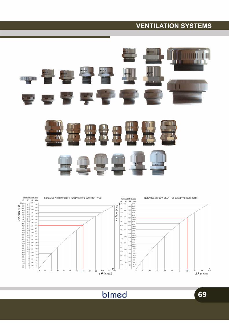
VENTILATION SYSTEMS
69
0 12010 20 90807060504030 110100
Δ P (in mbar)
Air
Flow
(inlt/
h )
20
40
60
80
100
120
140
160
180
200
220
240
260
280
300
320
340
360
380
400
420
440
10
20
30
40
50
60
70
80
100
110
120
130
140
150
160
170
190
180
200
90
123456789
101112131415161718192021222324252627282930
0,51,01,52,02,53,03,54,04,55,05,56,06,57,07,58,08,59,09,5
10,010,511,011,512,012,513,013,514,014,515,0
H UHS MPermeability Grade
15,516,016,517,017,518,0
31323334353637
INDICATIVE AIR FLOW GRAPH FOR BVPA-BVPB-BVQ-BBVP TYPES
0 10 20 807060504030 10090
�P (in mbar)
Air F
low
( in
lt/h )
H UHS MPermeability Grade
200
300
350
110
450
50
1100
900
1000
60
1300
1200
70
250
80
1400
1500
1600
800
700
20010
20
140
150
40
30 100500
600
50
100
400120
130
901700
1800
1900
500
100
400
300
2800
2700
2600
150
2000
2100
2200
2300
2500
2400
2900
1000
900
1100
1200
1300
1400
1500
1600
100
300
200
400
500
600
700
800
Δ
INDICATIVE AIR FLOW GRAPH FOR BVPX-BVPB-BBVPX TYPES
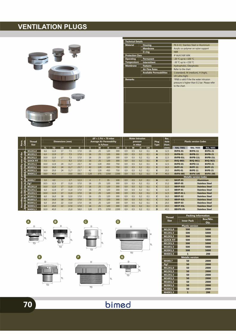
D
H
TD
TL
D
H
TD
TL
D
H
TD
TL
D
H
TD
TL
D
H
TD
TL
D
H
TD
TL
D
H
TD
TL
VENTILATION PLUGS
70
Thread Size
Packing Information
Inner Pack Box/Min.
Qty. Plastic version
M12X1,0 500 5000 M12X1,5 500 5000 M12X1,5 500 5000 QUICK FIT 500 5000 M12X1,5 500 5000 M16X1,5 500 5000 M20X1,5 500 5000 M40X1,5 1 200
Metalic version M4X0,7 50 2000 Pg7 50 2000 M12X1,0 50 2000 M12X1,5 50 2000 M12X1,5 50 2000 M16X1,5 50 2000 M16X1,5 50 2000 M20X1,5 50 2000 M20X1,5 50 2000 M40X1,5 1 200
Technical Details Material Housing PA 6-V2, Stainless Steel or Aluminium
Membrane Acrylic co-polymer on nylon support O-ring NBR
Protection Class IP 66/67/68*/69K Operating Temperature
Permanent -20 °C up to +100 °C Intermittent -30 °C up to +150 °C
Membrane Features Hydrophobic, Oleophobic Air Flow Rates Refer to the chart Available Permeabilities S (standard), M (medium), H (high),
UH (ultra high) Remarks *IP68 is valid if the the water intrusion
pressure is higher than 0.1 bar. Please refer to the chart.
Perm
. Co
de
Thread Size
Dimensions (mm) �P = 1 Psi = 70 mbar
Average Air Permeability in lt/hour
Water Intrusion pressure in mbar
Plug Type
Rec. Hole Diam. (mm)
Plastic version Codes
TL TD SW H D S M H UH S M H UH RAL 7001 RAL 7035 RAL 9005
Acc
ordi
ng t
o th
e ch
oose
n ai
r pe
rmea
bilit
y on
e of
the
le
tter
s (S
-M-H
-UH
) has
to b
e ad
ded
in f
ront
of t
he c
ode M12X1,0 6,6 12,0 17 7,5 17,0 16 25 120 300 0,9 0,5 0,2 0,1 A 12,5 BVPA-01 BVPA-11 BVPA-21
M12X1,5 6,0 12,0 17 7,5 17,0 16 25 120 300 0,9 0,5 0,2 0,1 A 12,5 BVPB-01 BVPB-11 BVPB-21 M12X1,5 10,0 12,0 17 7,5 17,0 16 25 120 300 0,9 0,5 0,2 0,1 A 12,5 BVPB-01L BVPB-11L BVPB-21L QUICK FIT 7,5 5,5 - 9,3 17,0 16 25 120 300 0,9 0,5 0,2 0,1 B 6,4 BVQ-M01 BVQ-M11 BVQ-M21 M12X1,5 10,0 12,0 24 11,7 23,7 42 120 450 750 0,9 0,5 0,2 0,1 E 12,5 BVPD-01 BVPD-11 BVPD-21 M16X1,5 10,0 16,0 24 11,7 23,7 42 120 450 750 0,9 0,5 0,2 0,1 E 16,5 BVPF-01 BVPF-11 BVPF-21 M20X1,5 10,0 20,0 24 11,7 23,7 42 120 450 750 0,9 0,5 0,2 0,1 E 20,5 BVPE-01 BVPE-11 BVPE-21 M40X1,5 18,0 40,0 - 19,0 59,5 120 375 1350 2200 0,9 0,5 0,2 0,1 F 40,5 BVPX-08S BVPX-18S BVPX-28S
Metallic version Codes M4X0,7 3,0 4,0 - 2,7 12,3 4 7 35 100 0,9 0,5 0,2 0,1 G 4,3 BAVP-01 Aluminium Pg7 10,5 12,5 17 11,0 17,0 16 25 120 300 0,9 0,5 0,2 0,1 C 13,2 BBVP-0S Stainless Steel M12X1,0 10,0 12,0 17 11,0 17,0 16 25 120 300 0,9 0,5 0,2 0,1 C 12,5 BBVP-01S Stainless Steel M12X1,5 6,0 12,0 17 11,0 17,0 16 25 120 300 0,9 0,5 0,2 0,1 C 12,5 BBVP-01 Stainless Steel M12X1,5 10,0 12,0 17 11,0 17,0 16 25 120 300 0,9 0,5 0,2 0,1 C 12,5 BBVP-01 L Stainless Steel M16X1,5 6,0 16,0 18 12,0 17,0 16 25 120 300 0,9 0,5 0,2 0,1 C 16,5 BBVP-02 Stainless Steel M16X1,5 6,0 16,0 18 16,0 17,0 16 25 120 300 0,9 0,5 0,2 0,1 C 16,5 BBVP-02L Stainless Steel M20X1,5 6,0 20,0 22 13,0 17,0 16 25 120 300 0,9 0,5 0,2 0,1 C 20,5 BBVP-03 Stainless Steel M20X1,5 6,0 20,0 22 17,0 17,0 16 25 120 300 0,9 0,5 0,2 0,1 C 20,5 BBVP-03L Stainless Steel M40X1,5 10,0 40,0 - 21,0 58,0 120 375 1350 2200 0,9 0,5 0,2 0,1 D 40,5 BBVPX-05 Stainless Steel
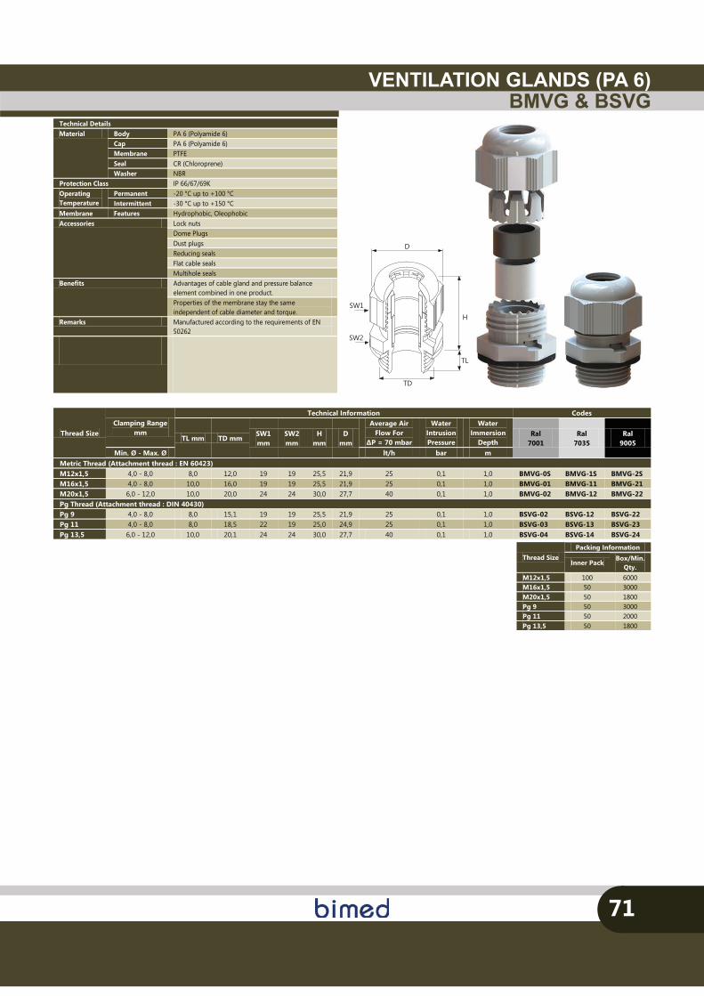
VENTILATION GLANDS (PA 6)BMVG & BSVG
71
Thread Size Packing Information
Inner Pack Box/Min.
Qty. M12x1,5 100 6000 M16x1,5 50 3000 M20x1,5 50 1800 Pg 9 50 3000 Pg 11 50 2000 Pg 13,5 50 1800
SW1
SW2
TD
TL
D
H
Technical Details Material Body PA 6 (Polyamide 6)
Cap PA 6 (Polyamide 6) Membrane PTFE Seal CR (Chloroprene) Washer NBR
Protection Class IP 66/67/69K Operating Temperature
Permanent -20 °C up to +100 °C Intermittent -30 °C up to +150 °C
Membrane Features Hydrophobic, Oleophobic Accessories Lock nuts
Dome Plugs Dust plugs Reducing seals Flat cable seals Multihole seals
Benefits Advantages of cable gland and pressure balance element combined in one product. Properties of the membrane stay the same independent of cable diameter and torque.
Remarks Manufactured according to the requirements of EN 50262
Thread Size Clamping Range
mm
Technical Information Codes
TL mm TD mm SW1 mm
SW2 mm
H mm
D mm
Average Air Flow For
�P = 70 mbar
Water Intrusion Pressure
Water Immersion
Depth Ral
7001 Ral
7035 Ral
9005 Min. Ø - Max. Ø lt/h bar m
Metric Thread (Attachment thread : EN 60423) M12x1,5 4,0 - 8,0 8,0 12,0 19 19 25,5 21,9 25 0,1 1,0 BMVG-0S BMVG-1S BMVG-2S M16x1,5 4,0 - 8,0 10,0 16,0 19 19 25,5 21,9 25 0,1 1,0 BMVG-01 BMVG-11 BMVG-21 M20x1,5 6,0 - 12,0 10,0 20,0 24 24 30,0 27,7 40 0,1 1,0 BMVG-02 BMVG-12 BMVG-22 Pg Thread (Attachment thread : DIN 40430) Pg 9 4,0 - 8,0 8,0 15,1 19 19 25,5 21,9 25 0,1 1,0 BSVG-02 BSVG-12 BSVG-22 Pg 11 4,0 - 8,0 8,0 18,5 22 19 25,0 24,9 25 0,1 1,0 BSVG-03 BSVG-13 BSVG-23 Pg 13,5 6,0 - 12,0 10,0 20,1 24 24 30,0 27,7 40 0,1 1,0 BSVG-04 BSVG-14 BSVG-24
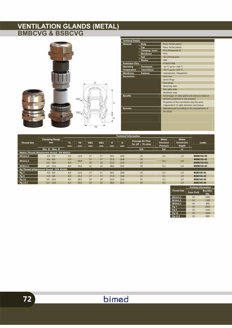
VENTILATION GLANDS (METAL)BMBCVG & BSBCVG
72
Thread Size Packing Information
Inner Pack Box/Min.
Qty. M12x1,5 50 2000 M16x1,5 50 1500 M20x1,5 50 800 Pg 7 50 2000 Pg 9 50 1500 Pg 11 50 1000 Pg 13,5 50 800
SW1
SW2
TD
TL
H
D
Thread Size Clamping Range
mm
Technical Information
Codes TL mm
TD mm
SW1 mm
SW2 mm
H mm
D mm
Average Air Flow For �P = 70 mbar
Water Intrusion Pressure
Water Immersion
Depth Min. Ø - Max. Ø lt/h bar m
Metric Thread (Attachment thread : EN 60423) M12x1,5 4,0 - 8,0 6,0 12,0 17 17 30,5 18,8 25 0,1 1,0 BMBCVG-0S
M16x1,5 4,0 - 8,0 5,0
16,0 17 17 27,0 18,8 25
0,1 1,0 BMBCVG-01
5,0 - 10,0 8,0 20 20 32,0 22,0 35 BMBCVG-01L M20x1,5 6,0 - 12,0 8,0 20,0 22 22 28,0 24,5 50 0,1 1,0 BMBCVG-02 Pg Thread (Attachment thread : DIN 40430) Pg 7 4,0 - 8,0 8,0 12,4 17 17 30,5 18,8 25 0,1 1,0 BSBCVG-01 Pg 9 4,0 - 8,0 6,0 15,2 17 17 27,0 18,8 25 0,1 1,0 BSBCVG-02 Pg 11 5,0 - 10,0 8,0 18,5 20 20 32,0 22,0 35 0,1 1,0 BSBCVG-03 Pg 13,5 6,0 - 12,0 6,5 20,4 22 22 28,0 24,5 50 0,1 1,0 BSBCVG-04
Technical Details Material Body Brass, Nickel plated
Cap Brass, Nickel plated Clamping Insert PA 6 (Polyamide 6) Membrane PTFE Seal CR (Chloroprene) Washer NBR
Protection Class IP 66/67/69K Operating Temperature
Permanent -20 °C up to +100 °C Intermittent -30 °C up to +150 °C
Membrane Features Hydrophobic, Oleophobic Accessories Lock nuts
Dome Plugs Dust plugs Reducing seals Flat cable seals Multihole seals
Benefits Advantages of cable gland and pressure balance element combined in one product. Properties of the membrane stay the same independent of cable diameter and torque.
Remarks Manufactured according to the requirements of EN 50262

CUSTOMER ORIENTEDPRODUCTS
Many of the products manufactured by Bimed are designed and manufactured for special applica�ons. These “custom-made” parts can be produced with either modifying our exis�ng injec�on tools or realising completely new tools. Moreover; on new projects, prototype samples for our customers can also be created together with our engineering department. In this part of overview, we would like to show some of our “customer-oriented” parts. The explained range will give our customers the chance of analysing our abili�es and crea�ng solu�ons to their problems. Similar to our ac�vi�es in plas�c products, we also develop several custom-made products in brass and stainless steel for our customers. We use exis�ng turning and transfer machines in these products. In addi�on, die cas�ng process is also used in our production opera�ons. The main aim of this ac�vity is suppor�ng our customers with some customer friendly products which can not be obtained from our compe�tors due to their lower produc�on capacity and insu�cient investment budgets.
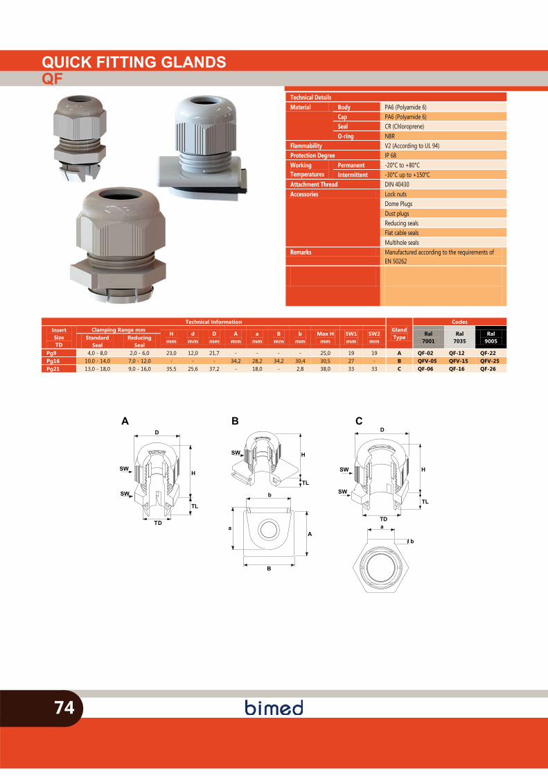
QUICK FITTING GLANDSQF
74
A
TD
SW
D
H
SW
TL
B
b
B
aA
SW H
TL
C
a
b
D
HSW
SW
TL
TD
Technical Information Gland Type
Codes Insert Size TD
Clamping Range mm H
mm d
mm D
mm A
mm a
mm B
mm b
mm Max H
mm SW1 mm
SW2 mm
Ral 7001
Ral 7035
Ral 9005 Standard
Seal Reducing
Seal Pg9 4,0 - 8,0 2,0 - 6,0 23,0 12,0 21,7 - - - - 25,0 19 19 A QF-02 QF-12 QF-22 Pg16 10,0 - 14,0 7,0 - 12,0 - - - 34,2 28,2 34,2 30,4 30,5 27 - B QFV-05 QFV-15 QFV-25 Pg21 13,0 - 18,0 9,0 - 16,0 35,5 25,6 37,2 - 18,0 - 2,8 38,0 33 33 C QF-06 QF-16 QF-26
Technical Details Material Body PA6 (Polyamide 6)
Cap PA6 (Polyamide 6) Seal CR (Chloroprene) O-ring NBR
Flammability V2 (According to UL 94) Protection Degree IP 68 Working Temperatures
Permanent -20°C to +80°C Intermittent -30°C up to +150°C
Attachment Thread DIN 40430 Accessories Lock nuts
Dome Plugs Dust plugs Reducing seals Flat cable seals Multihole seals
Remarks Manufactured according to the requirements of EN 50262
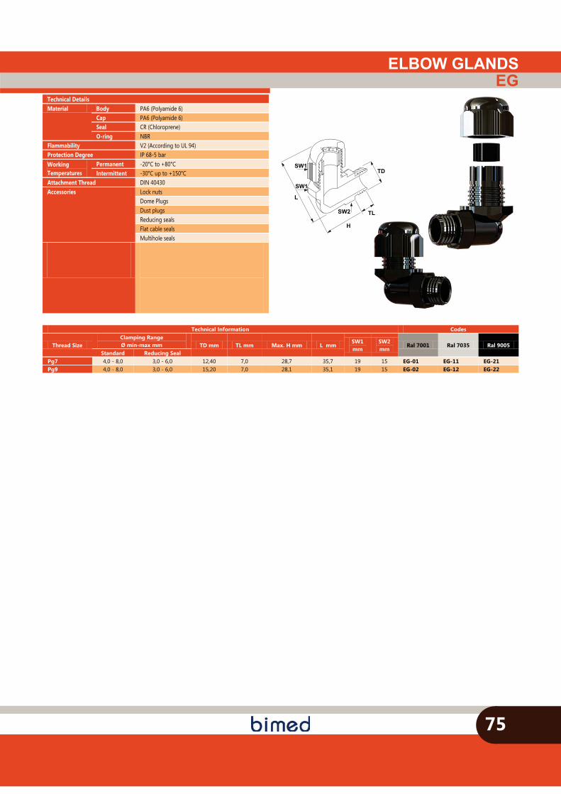
ELBOW GLANDSEG
H
TD
SW2
SW1
SW1
L
TL
75
Technical Information Codes
Thread Size Clamping Range Ø min-max mm TD mm TL mm Max. H mm L mm
SW1 mm
SW2 mm
Ral 7001 Ral 7035 Ral 9005 Standard Reducing Seal
Pg7 4,0 - 8,0 3,0 - 6,0 12,40 7,0 28,7 35,7 19 15 EG-01 EG-11 EG-21 Pg9 4,0 - 8,0 3,0 - 6,0 15,20 7,0 28,1 35,1 19 15 EG-02 EG-12 EG-22
Technical Details Material Body PA6 (Polyamide 6)
Cap PA6 (Polyamide 6) Seal CR (Chloroprene) O-ring NBR
Flammability V2 (According to UL 94) Protection Degree IP 68-5 bar Working Temperatures
Permanent -20°C to +80°C Intermittent -30°C up to +150°C
Attachment Thread DIN 40430 Accessories Lock nuts
Dome Plugs Dust plugs Reducing seals Flat cable seals Multihole seals
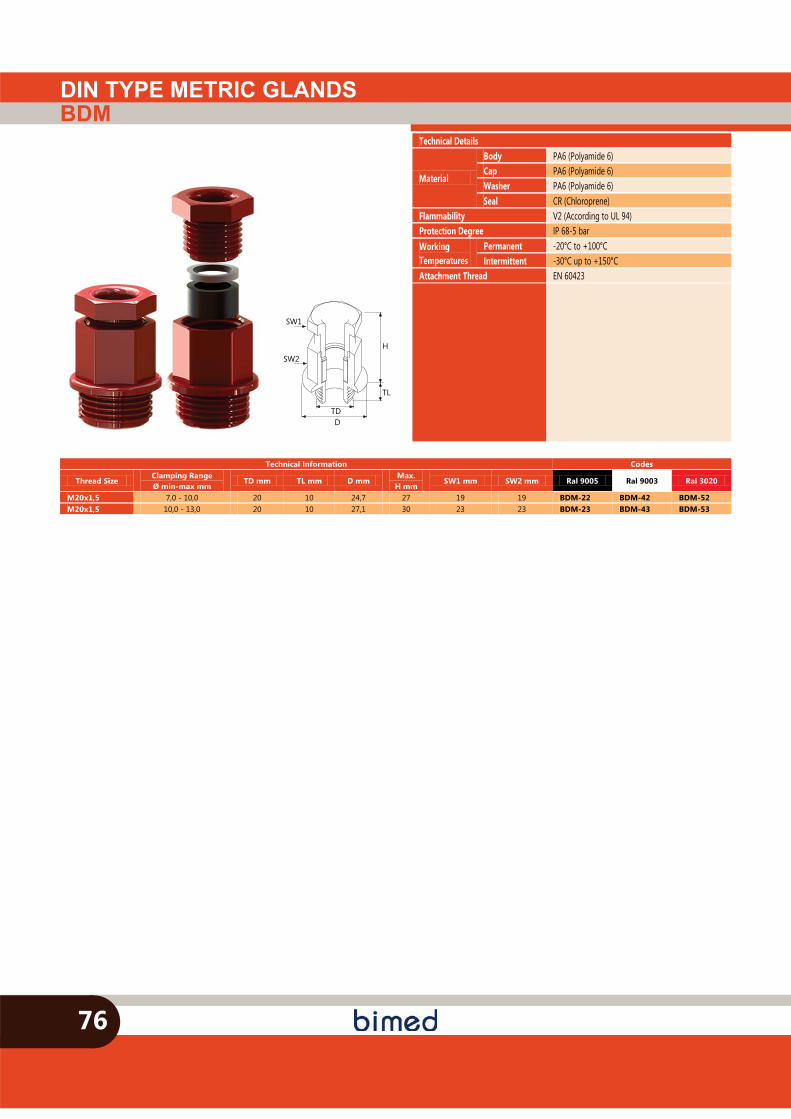
DIN TYPE METRIC GLANDSBDM
SW1
SW2
DTD
H
TL
76
Technical Details
Material
Body PA6 (Polyamide 6) Cap PA6 (Polyamide 6) Washer PA6 (Polyamide 6) Seal CR (Chloroprene)
Flammability V2 (According to UL 94) Protection Degree IP 68-5 bar Working Temperatures
Permanent -20°C to +100°C Intermittent -30°C up to +150°C
Attachment Thread EN 60423
Technical Information Codes
Thread Size Clamping Range Ø min-max mm
TD mm TL mm D mm Max.
H mm SW1 mm SW2 mm Ral 9005 Ral 9003 Ral 3020
M20x1,5 7,0 - 10,0 20 10 24,7 27 19 19 BDM-22 BDM-42 BDM-52 M20x1,5 10,0 - 13,0 20 10 27,1 30 23 23 BDM-23 BDM-43 BDM-53
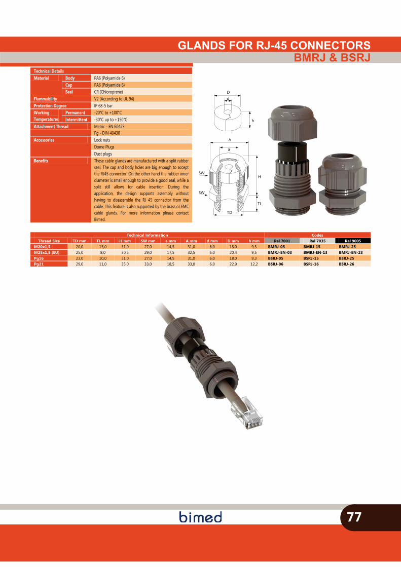
GLANDS FOR RJ-45 CONNECTORSBMRJ & BSRJ
77
Technical Information Codes Thread Size TD mm TL mm H mm SW mm a mm A mm d mm D mm h mm Ral 7001 Ral 7035 Ral 9005
M20x1,5 20,0 15,0 31,0 27,0 14,5 31,0 6,0 18,0 9,3 BMRJ-05 BMRJ-15 BMRJ-25 M25x1,5 (EU) 25,0 8,0 30,5 29,0 17,5 32,5 6,0 20,4 9,5 BMRJ-EN-03 BMRJ-EN-13 BMRJ-EN-23 Pg16 23,0 10,0 31,0 27,0 14,5 31,0 6,0 18,0 9,3 BSRJ-05 BSRJ-15 BSRJ-25 Pg21 29,0 11,0 35,0 33,0 18,5 33,0 6,0 22,9 12,2 BSRJ-06 BSRJ-16 BSRJ-26
SW
TD
H
TL
SW
A
a
Dd
h
Technical Details Material Body PA6 (Polyamide 6)
Cap PA6 (Polyamide 6) Seal CR (Chloroprene)
Flammability V2 (According to UL 94) Protection Degree IP 68-5 bar Working Temperatures
Permanent -20°C to +100°C Intermittent -30°C up to +150°C
Attachment Thread Metric - EN 60423 Pg - DIN 40430
Accessories Lock nuts Dome Plugs Dust plugs
Benefits These cable glands are manufactured with a split rubber seal. The cap and body holes are big enough to accept the RJ45 connector. On the other hand the rubber inner diameter is small enough to provide a good seal, while a split still allows for cable insertion. During the application, the design supports assembly without having to disassemble the RJ 45 connector from the cable. This feature is also supported by the brass or EMC cable glands. For more information please contact Bimed.
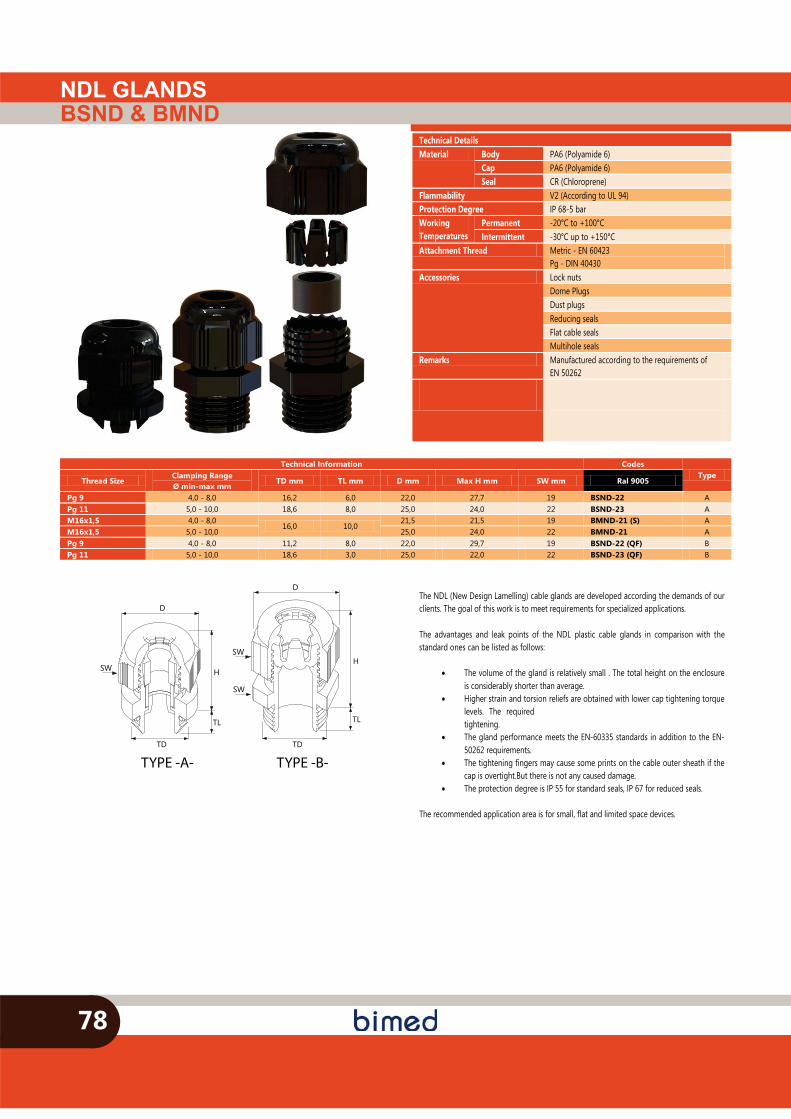
NDL GLANDSBSND & BMND
78
TYPE -A-
SW
TD
TL
H
D
SW
TD
H
TL
D
SW
TYPE -B-
The NDL (New Design Lamelling) cable glands are developed according the demands of our clients. The goal of this work is to meet requirements for specialized applications. The advantages and leak points of the NDL plastic cable glands in comparison with the standard ones can be listed as follows:
� The volume of the gland is relatively small . The total height on the enclosure is considerably shorter than average.
� Higher strain and torsion reliefs are obtained with lower cap tightening torque levels. The required tightening.
� The gland performance meets the EN-60335 standards in addition to the EN-50262 requirements.
� The tightening fingers may cause some prints on the cable outer sheath if the cap is overtight.But there is not any caused damage.
� The protection degree is IP 55 for standard seals, IP 67 for reduced seals.
The recommended application area is for small, flat and limited space devices.
Technical Details Material Body PA6 (Polyamide 6)
Cap PA6 (Polyamide 6) Seal CR (Chloroprene)
Flammability V2 (According to UL 94) Protection Degree IP 68-5 bar Working Temperatures
Permanent -20°C to +100°C Intermittent -30°C up to +150°C
Attachment Thread Metric - EN 60423 Pg - DIN 40430
Accessories Lock nuts Dome Plugs Dust plugs Reducing seals Flat cable seals Multihole seals
Remarks Manufactured according to the requirements of EN 50262
Technical Information Codes Type
Thread Size Clamping Range Ø min-max mm
TD mm TL mm D mm Max H mm SW mm Ral 9005
Pg 9 4,0 - 8,0 16,2 6,0 22,0 27,7 19 BSND-22 A Pg 11 5,0 - 10,0 18,6 8,0 25,0 24,0 22 BSND-23 A M16x1,5 4,0 - 8,0
16,0 10,0 21,5 21,5 19 BMND-21 (S) A
M16x1,5 5,0 - 10,0 25,0 24,0 22 BMND-21 A Pg 9 4,0 - 8,0 11,2 8,0 22,0 29,7 19 BSND-22 (QF) B Pg 11 5,0 - 10,0 18,6 3,0 25,0 22,0 22 BSND-23 (QF) B
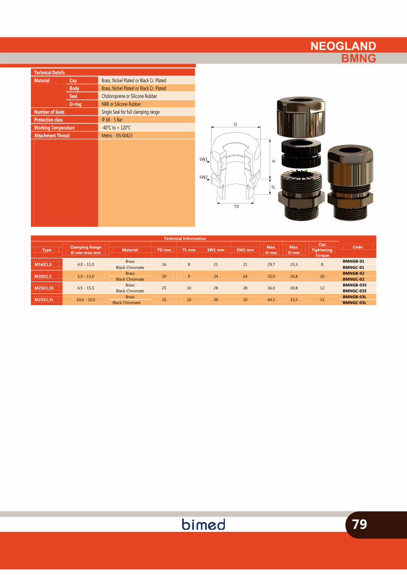
NEOGLANDBMNG
79
SW1
TD
H
TL
SW2
D
Technical Details Material Cap Brass, Nickel Plated or Black Cr. Plated
Body Brass, Nickel Plated or Black Cr. Plated Seal Choloroprene or Silicone Rubber O-ring NBR or Silicone Rubber
Number of Seals Single Seal for full clamping range Protection class IP 68 - 5 Bar Working Temperature -40°C to + 120°C Attachment Thread Metric - EN 60423
Technical Information
Code Type
Clamping Range Ø min-max mm
Material TD mm TL mm SW1 mm SW2 mm Max.
H mm Max. D mm
Cap Tightening
Torque
M16X1,5 4,0 - 11,0 Brass
16 8 21 21 29,7 23,3 8 BMNGB-01
Black Chromate BMNGC-01
M20X1,5 5,0 - 13,0 Brass
20 9 24 24 32,0 26,8 10 BMNGB-02
Black Chromate BMNGC-02
M25X1,5S 6,5 - 15,5 Brass
25 10 28 28 36,0 30,8 12 BMNGB-03S
Black Chromate BMNGC-03S
M25X1,5L 10,0 - 20,0 Brass
25 10 30 30 44,5 33,5 15 BMNGB-03L
Black Chromate BMNGC-03L
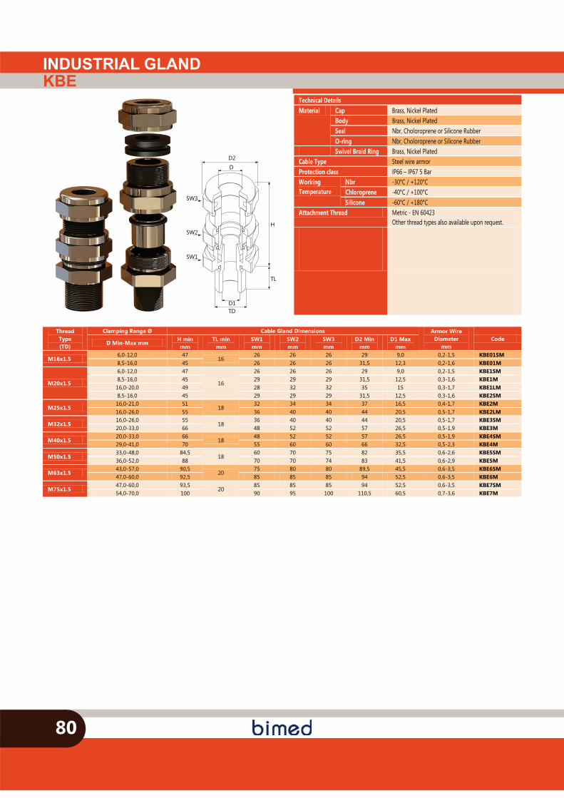
INDUSTRIAL GLANDKBE
80
Technical Details Material Cap Brass, Nickel Plated
Body Brass, Nickel Plated Seal Nbr, Choloroprene or Silicone Rubber O-ring Nbr, Choloroprene or Silicone Rubber
Swivel Braid Ring Brass, Nickel Plated Cable Type Steel wire armor Protection class IP66 – IP67 5 Bar Working Temperature
Nbr -30°C / +120°C Chloroprene -40°C / +100°C Silicone -60°C / +180°C
Attachment Thread Metric - EN 60423 Other thread types also available upon request.
SW2
TD
H
TL
D2
SW3
SW1
D1
D
Thread Type (TD)
Clamping Range Ø Cable Gland Dimensions Armor Wire Diameter
mm Code
D Min-Max mm H min mm
TL min mm
SW1 mm
SW2 mm
SW3 mm
D2 Min mm
D1 Max mm
M16x1.5 6,0-12,0 47
16 26 26 26 29 9,0 0,2-1,5 KBE01SM
8,5-16,0 45 26 26 26 31,5 12,3 0,2-1,6 KBE01M
M20x1.5
6,0-12,0 47
16
26 26 26 29 9,0 0,2-1,5 KBE1SM 8,5-16,0 45 29 29 29 31,5 12,5 0,3-1,6 KBE1M 16,0-20,0 49 28 32 32 35 15 0,3-1,7 KBE1LM 8,5-16,0 45 29 29 29 31,5 12,5 0,3-1,6 KBE2SM
M25x1.5 16,0-21,0 51
18 32 34 34 37 16,5 0,4-1,7 KBE2M
16,0-26,0 55 36 40 40 44 20,5 0,5-1,7 KBE2LM
M32x1.5 16,0-26,0 55
18 36 40 40 44 20,5 0,5-1,7 KBE3SM
20,0-33,0 66 48 52 52 57 26,5 0,5-1,9 KBE3M
M40x1.5 20,0-33,0 66
18 48 52 52 57 26,5 0,5-1,9 KBE4SM
29,0-41,0 70 55 60 60 66 32,5 0,5-2,3 KBE4M
M50x1.5 33,0-48,0 84,5
18 60 70 75 82 35,5 0,6-2,6 KBE5SM
36,0-52,0 88 70 70 74 83 41,5 0,6-2,9 KBE5M
M63x1.5 43,0-57,0 90,5
20 75 80 80 89,5 45,5 0,6-3,5 KBE6SM
47,0-60,0 92,5 85 85 85 94 52,5 0,6-3,5 KBE6M
M75x1.5 47,0-60,0 93,5
20 85 85 85 94 52,5 0,6-3,5 KBE7SM
54,0-70,0 100 90 95 100 110,5 60,5 0,7-3,6 KBE7M
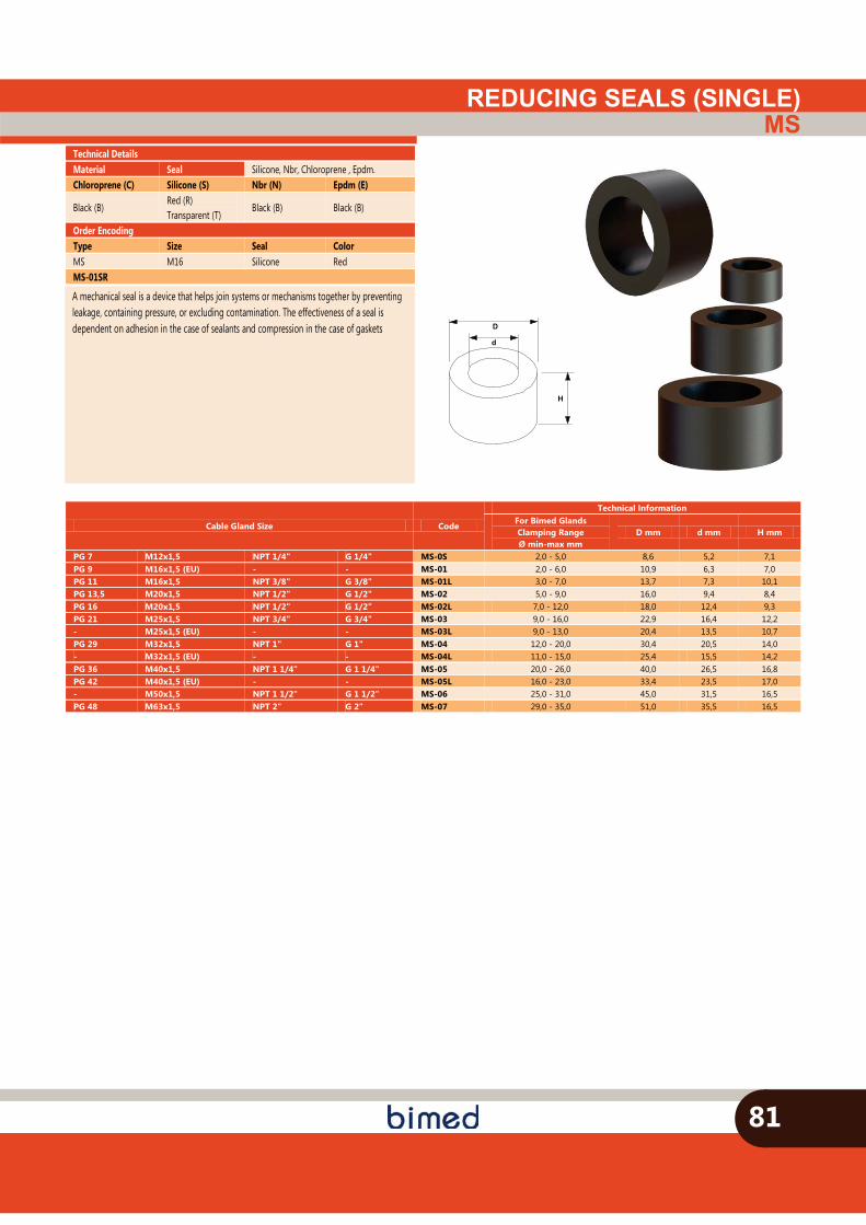
REDUCING SEALS (SINGLE)MS
81
D
d
H
Cable Gland Size Code
Technical Information For Bimed Glands Clamping Range Ø min-max mm
D mm d mm H mm
PG 7 M12x1,5 NPT 1/4" G 1/4" MS-0S 2,0 - 5,0 8,6 5,2 7,1 PG 9 M16x1,5 (EU) - - MS-01 2,0 - 6,0 10,9 6,3 7,0 PG 11 M16x1,5 NPT 3/8" G 3/8" MS-01L 3,0 - 7,0 13,7 7,3 10,1 PG 13,5 M20x1,5 NPT 1/2" G 1/2" MS-02 5,0 - 9,0 16,0 9,4 8,4 PG 16 M20x1,5 NPT 1/2" G 1/2" MS-02L 7,0 - 12,0 18,0 12,4 9,3 PG 21 M25x1,5 NPT 3/4" G 3/4" MS-03 9,0 - 16,0 22,9 16,4 12,2 - M25x1,5 (EU) - - MS-03L 9,0 - 13,0 20,4 13,5 10,7 PG 29 M32x1,5 NPT 1" G 1" MS-04 12,0 - 20,0 30,4 20,5 14,0 - M32x1,5 (EU) - - MS-04L 11,0 - 15,0 25,4 15,5 14,2 PG 36 M40x1,5 NPT 1 1/4" G 1 1/4" MS-05 20,0 - 26,0 40,0 26,5 16,8 PG 42 M40x1,5 (EU) - - MS-05L 16,0 - 23,0 33,4 23,5 17,0 - M50x1,5 NPT 1 1/2" G 1 1/2" MS-06 25,0 - 31,0 45,0 31,5 16,5 PG 48 M63x1,5 NPT 2" G 2" MS-07 29,0 - 35,0 51,0 35,5 16,5
Technical Details Material Seal Silicone, Nbr, Chloroprene , Epdm. Chloroprene (C) Silicone (S) Nbr (N) Epdm (E)
Black (B) Red (R) Transparent (T)
Black (B) Black (B)
Order Encoding Type Size Seal Color MS M16 Silicone Red MS-01SR
A mechanical seal is a device that helps join systems or mechanisms together by preventing leakage, containing pressure, or excluding contamination. The effectiveness of a seal is dependent on adhesion in the case of sealants and compression in the case of gaskets
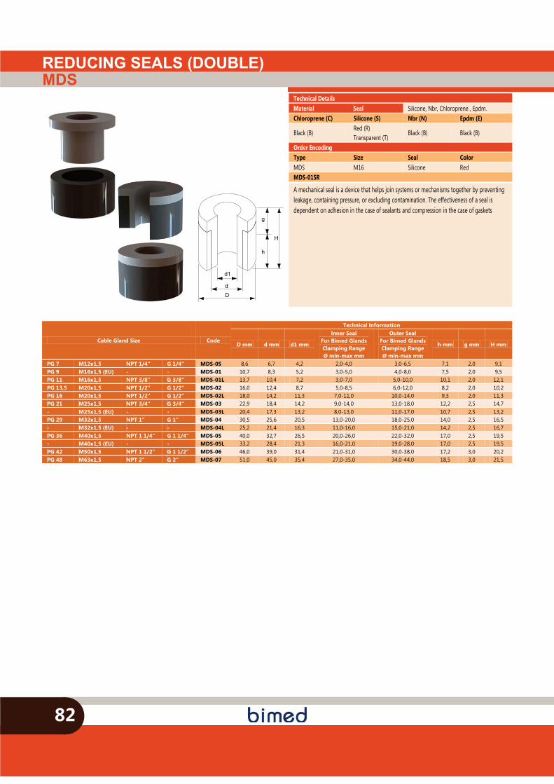
REDUCING SEALS (DOUBLE)MDS
82
h
H
g
d1
dD
Technical Details Material Seal Silicone, Nbr, Chloroprene , Epdm. Chloroprene (C) Silicone (S) Nbr (N) Epdm (E)
Black (B) Red (R) Transparent (T)
Black (B) Black (B)
Order Encoding Type Size Seal Color MDS M16 Silicone Red MDS-01SR
A mechanical seal is a device that helps join systems or mechanisms together by preventing leakage, containing pressure, or excluding contamination. The effectiveness of a seal is dependent on adhesion in the case of sealants and compression in the case of gaskets
Cable Gland Size Code
Technical Information
D mm d mm d1 mm
Inner Seal For Bimed Glands Clamping Range Ø min-max mm
Outer Seal For Bimed Glands Clamping Range Ø min-max mm
h mm g mm H mm
PG 7 M12x1,5 NPT 1/4" G 1/4" MDS-0S 8,6 6,7 4,2 2,0-4,0 3,0-6,5 7,1 2,0 9,1 PG 9 M16x1,5 (EU) - - MDS-01 10,7 8,3 5,2 3,0-5,0 4,0-8,0 7,5 2,0 9,5 PG 11 M16x1,5 NPT 3/8" G 3/8" MDS-01L 13,7 10,4 7,2 3,0-7,0 5,0-10,0 10,1 2,0 12,1 PG 13,5 M20x1,5 NPT 1/2" G 1/2" MDS-02 16,0 12,4 8,7 5,0-8,5 6,0-12,0 8,2 2,0 10,2 PG 16 M20x1,5 NPT 1/2" G 1/2" MDS-02L 18,0 14,2 11,3 7,0-11,0 10,0-14,0 9,3 2,0 11,3 PG 21 M25x1,5 NPT 3/4" G 3/4" MDS-03 22,9 18,4 14,2 9,0-14,0 13,0-18,0 12,2 2,5 14,7 - M25x1,5 (EU) - - MDS-03L 20,4 17,3 13,2 8,0-13,0 11,0-17,0 10,7 2,5 13,2 PG 29 M32x1,5 NPT 1" G 1" MDS-04 30,5 25,6 20,5 13,0-20,0 18,0-25,0 14,0 2,5 16,5 - M32x1,5 (EU) - - MDS-04L 25,2 21,4 16,3 11,0-16,0 15,0-21,0 14,2 2,5 16,7 PG 36 M40x1,5 NPT 1 1/4" G 1 1/4" MDS-05 40,0 32,7 26,5 20,0-26,0 22,0-32,0 17,0 2,5 19,5 - M40x1,5 (EU) - - MDS-05L 33,2 28,4 21,3 16,0-21,0 19,0-28,0 17,0 2,5 19,5 PG 42 M50x1,5 NPT 1 1/2" G 1 1/2" MDS-06 46,0 39,0 31,4 21,0-31,0 30,0-38,0 17,2 3,0 20,2 PG 48 M63x1,5 NPT 2" G 2" MDS-07 51,0 45,0 35,4 27,0-35,0 34,0-44,0 18,5 3,0 21,5
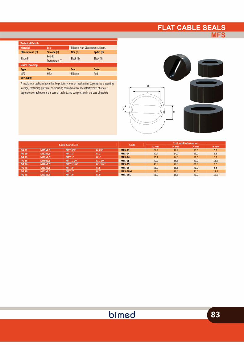
D
A
HB
FLAT CABLE SEALSMFS
83
H
Technical Details Material Seal Silicone, Nbr, Chloroprene , Epdm. Chloroprene (C) Silicone (S) Nbr (N) Epdm (E)
Black (B) Red (R) Transparent (T)
Black (B) Black (B)
Order Encoding Type Size Seal Color MFS M32 Silicone Red MFS-04SR
A mechanical seal is a device that helps join systems or mechanisms together by preventing leakage, containing pressure, or excluding contamination. The effectiveness of a seal is dependent on adhesion in the case of sealants and compression in the case of gaskets
Cable Gland Size Code Technical Information
D mm H mm A mm B mm PG 21 M25x1,5 NPT 3/4" G 3/4" MFS-03 22,9 12,2 19,0 5,8 PG 29 M32x1,5 NPT 1" G 1" MFS-04 30,4 14,0 19,0 5,8 PG 29 M32x1,5 NPT 1" G 1" MFS-04L 30,4 14,0 22,0 7,8 PG 36 M40x1,5 NPT 1 1/4" G 1 1/4" MFS-05 40,0 16,8 31,0 11,0 PG 36 M40x1,5 NPT 1 1/4" G 1 1/4" MFS-05L 40,0 16,8 31,0 5,5 PG 48 M63x1,5 NPT 2" G 2" MFS-06 51,0 18,5 43,0 5,5 PG 48 M63x1,5 NPT 2" G 2" MFS-06M 51,0 18,5 43,0 11,0 PG 48 M63x1,5 NPT 2" G 2" MFS-06L 51,0 18,5 43,0 15,5
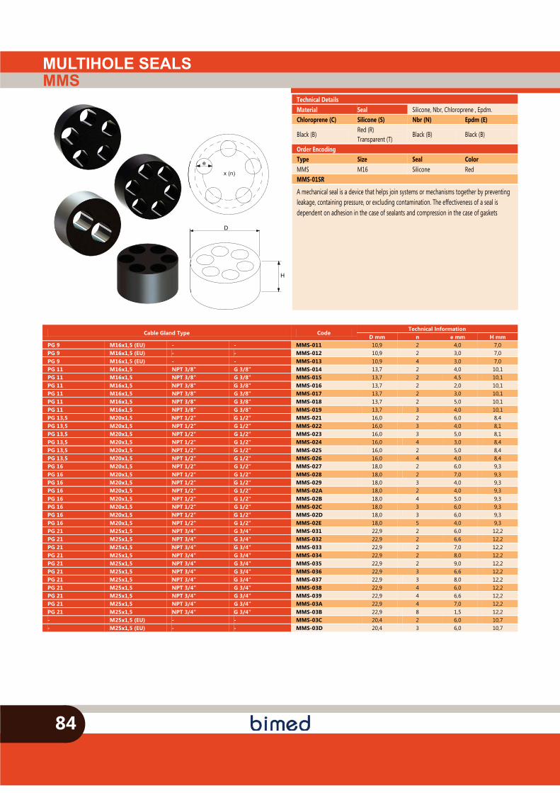
H
D
x (n)
e
MULTIHOLE SEALSMMS
84
Technical Details Material Seal Silicone, Nbr, Chloroprene , Epdm. Chloroprene (C) Silicone (S) Nbr (N) Epdm (E)
Black (B) Red (R) Transparent (T)
Black (B) Black (B)
Order Encoding Type Size Seal Color MMS M16 Silicone Red MMS-01SR
A mechanical seal is a device that helps join systems or mechanisms together by preventing leakage, containing pressure, or excluding contamination. The effectiveness of a seal is dependent on adhesion in the case of sealants and compression in the case of gaskets
Cable Gland Type Code Technical Information
D mm n e mm H mm PG 9 M16x1,5 (EU) - - MMS-011 10,9 2 4,0 7,0 PG 9 M16x1,5 (EU) - - MMS-012 10,9 2 3,0 7,0 PG 9 M16x1,5 (EU) - - MMS-013 10,9 4 3,0 7,0 PG 11 M16x1,5 NPT 3/8" G 3/8" MMS-014 13,7 2 4,0 10,1 PG 11 M16x1,5 NPT 3/8" G 3/8" MMS-015 13,7 2 4,5 10,1 PG 11 M16x1,5 NPT 3/8" G 3/8" MMS-016 13,7 2 2,0 10,1 PG 11 M16x1,5 NPT 3/8" G 3/8" MMS-017 13,7 2 3,0 10,1 PG 11 M16x1,5 NPT 3/8" G 3/8" MMS-018 13,7 2 5,0 10,1 PG 11 M16x1,5 NPT 3/8" G 3/8" MMS-019 13,7 3 4,0 10,1 PG 13,5 M20x1,5 NPT 1/2" G 1/2" MMS-021 16,0 2 6,0 8,4 PG 13,5 M20x1,5 NPT 1/2" G 1/2" MMS-022 16,0 3 4,0 8,1 PG 13,5 M20x1,5 NPT 1/2" G 1/2" MMS-023 16,0 3 5,0 8,1 PG 13,5 M20x1,5 NPT 1/2" G 1/2" MMS-024 16,0 4 3,0 8,4 PG 13,5 M20x1,5 NPT 1/2" G 1/2" MMS-025 16,0 2 5,0 8,4 PG 13,5 M20x1,5 NPT 1/2" G 1/2" MMS-026 16,0 4 4,0 8,4 PG 16 M20x1,5 NPT 1/2" G 1/2" MMS-027 18,0 2 6,0 9,3 PG 16 M20x1,5 NPT 1/2" G 1/2" MMS-028 18,0 2 7,0 9,3 PG 16 M20x1,5 NPT 1/2" G 1/2" MMS-029 18,0 3 4,0 9,3 PG 16 M20x1,5 NPT 1/2" G 1/2" MMS-02A 18,0 2 4,0 9,3 PG 16 M20x1,5 NPT 1/2" G 1/2" MMS-02B 18,0 4 5,0 9,3 PG 16 M20x1,5 NPT 1/2" G 1/2" MMS-02C 18,0 3 6,0 9,3 PG 16 M20x1,5 NPT 1/2" G 1/2" MMS-02D 18,0 3 6,0 9,3 PG 16 M20x1,5 NPT 1/2" G 1/2" MMS-02E 18,0 5 4,0 9,3 PG 21 M25x1,5 NPT 3/4" G 3/4" MMS-031 22,9 2 6,0 12,2 PG 21 M25x1,5 NPT 3/4" G 3/4" MMS-032 22,9 2 6,6 12,2 PG 21 M25x1,5 NPT 3/4" G 3/4" MMS-033 22,9 2 7,0 12,2 PG 21 M25x1,5 NPT 3/4" G 3/4" MMS-034 22,9 2 8,0 12,2 PG 21 M25x1,5 NPT 3/4" G 3/4" MMS-035 22,9 2 9,0 12,2 PG 21 M25x1,5 NPT 3/4" G 3/4" MMS-036 22,9 3 6,6 12,2 PG 21 M25x1,5 NPT 3/4" G 3/4" MMS-037 22,9 3 8,0 12,2 PG 21 M25x1,5 NPT 3/4" G 3/4" MMS-038 22,9 4 6,0 12,2 PG 21 M25x1,5 NPT 3/4" G 3/4" MMS-039 22,9 4 6,6 12,2 PG 21 M25x1,5 NPT 3/4" G 3/4" MMS-03A 22,9 4 7,0 12,2 PG 21 M25x1,5 NPT 3/4" G 3/4" MMS-03B 22,9 8 1,5 12,2 - M25x1,5 (EU) - - MMS-03C 20,4 2 6,0 10,7 - M25x1,5 (EU) - - MMS-03D 20,4 3 6,0 10,7
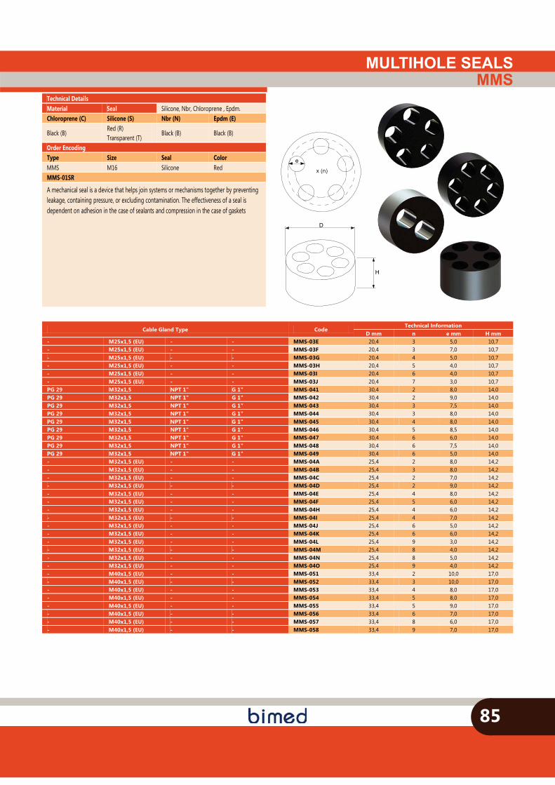
MULTIHOLE SEALSMMS
85
Technical Details Material Seal Silicone, Nbr, Chloroprene , Epdm. Chloroprene (C) Silicone (S) Nbr (N) Epdm (E)
Black (B) Red (R) Transparent (T)
Black (B) Black (B)
Order Encoding Type Size Seal Color MMS M16 Silicone Red MMS-01SR
A mechanical seal is a device that helps join systems or mechanisms together by preventing leakage, containing pressure, or excluding contamination. The effectiveness of a seal is dependent on adhesion in the case of sealants and compression in the case of gaskets
Cable Gland Type Code Technical Information
D mm n e mm H mm - M25x1,5 (EU) - - MMS-03E 20,4 3 5,0 10,7 - M25x1,5 (EU) - - MMS-03F 20,4 3 7,0 10,7 - M25x1,5 (EU) - - MMS-03G 20,4 4 5,0 10,7 - M25x1,5 (EU) - - MMS-03H 20,4 5 4,0 10,7 - M25x1,5 (EU) - - MMS-03I 20,4 6 4,0 10,7 - M25x1,5 (EU) - - MMS-03J 20,4 7 3,0 10,7 PG 29 M32x1,5 NPT 1" G 1" MMS-041 30,4 2 8,0 14,0 PG 29 M32x1,5 NPT 1" G 1" MMS-042 30,4 2 9,0 14,0 PG 29 M32x1,5 NPT 1" G 1" MMS-043 30,4 3 7,5 14,0 PG 29 M32x1,5 NPT 1" G 1" MMS-044 30,4 3 8,0 14,0 PG 29 M32x1,5 NPT 1" G 1" MMS-045 30,4 4 8,0 14,0 PG 29 M32x1,5 NPT 1" G 1" MMS-046 30,4 5 8,5 14,0 PG 29 M32x1,5 NPT 1" G 1" MMS-047 30,4 6 6,0 14,0 PG 29 M32x1,5 NPT 1" G 1" MMS-048 30,4 6 7,5 14,0 PG 29 M32x1,5 NPT 1" G 1" MMS-049 30,4 6 5,0 14,0 - M32x1,5 (EU) - - MMS-04A 25,4 2 8,0 14,2 - M32x1,5 (EU) - - MMS-04B 25,4 3 8,0 14,2 - M32x1,5 (EU) - - MMS-04C 25,4 2 7,0 14,2 - M32x1,5 (EU) - - MMS-04D 25,4 2 9,0 14,2 - M32x1,5 (EU) - - MMS-04E 25,4 4 8,0 14,2 - M32x1,5 (EU) - - MMS-04F 25,4 5 6,0 14,2 - M32x1,5 (EU) - - MMS-04H 25,4 4 6,0 14,2 - M32x1,5 (EU) - - MMS-04I 25,4 4 7,0 14,2 - M32x1,5 (EU) - - MMS-04J 25,4 6 5,0 14,2 - M32x1,5 (EU) - - MMS-04K 25,4 6 6,0 14,2 - M32x1,5 (EU) - - MMS-04L 25,4 9 3,0 14,2 - M32x1,5 (EU) - - MMS-04M 25,4 8 4,0 14,2 - M32x1,5 (EU) - - MMS-04N 25,4 8 5,0 14,2 - M32x1,5 (EU) - - MMS-04O 25,4 9 4,0 14,2 - M40x1,5 (EU) - - MMS-051 33,4 2 10,0 17,0 - M40x1,5 (EU) - - MMS-052 33,4 3 10,0 17,0 - M40x1,5 (EU) - - MMS-053 33,4 4 8,0 17,0 - M40x1,5 (EU) - - MMS-054 33,4 5 8,0 17,0 - M40x1,5 (EU) - - MMS-055 33,4 5 9,0 17,0 - M40x1,5 (EU) - - MMS-056 33,4 6 7,0 17,0 - M40x1,5 (EU) - - MMS-057 33,4 8 6,0 17,0 - M40x1,5 (EU) - - MMS-058 33,4 9 7,0 17,0
H
D
x (n)
e
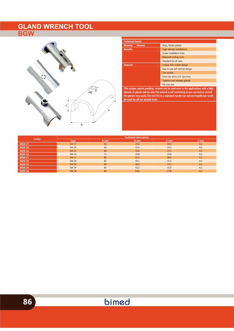
GLAND WRENCH TOOLBGW
86
B
A
C
E
Technical Details Material Wrench Brass, Nickel plated Benefits High-density installations.
Lower installation time. Reduced tooling costs. Standard for all sizes.
Features Unique slim socket design. Easy to use self-ratchet design. One socket Drive bar drive 1/4" (6,4 mm) Tightens and releases glands Fits one size
This unique- patent pending- wrench can be used even in the applications with a high density of glands side by side.The wrench is self ratcheting so you can lock or unlock the glands very easily.The tool fits to a standard handle bar and one handle bar could be used for all our wrench tools.
Codes Technical Information
Type A mm B mm C mm E mm BGW 17 SW 17 54 25,6 20,5 6,5 BGW 20 SW 20 66 31,0 24,2 6,5 BGW 22 SW 22 68 32,8 25,1 6,5 BGW 24 SW 24 72 35,8 25,8 6,5 BGW 27 SW 27 80 41,0 28,6 6,5 BGW 29 SW 29 85 45,1 31,5 6,5 BGW 30 SW 30 86 46,5 33,2 6,5 BGW 34 SW 34 86 50,2 35,9 6,5 BGW 36 SW 36 86 54,6 37,8 6,5
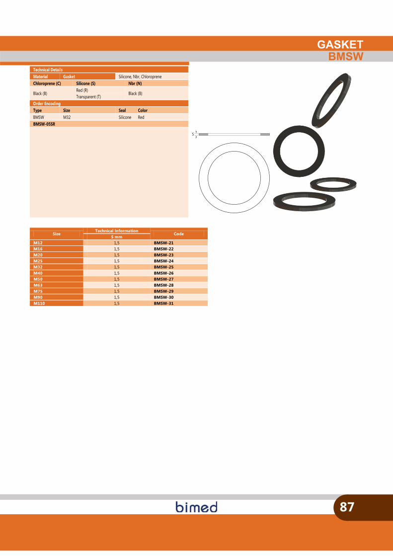
GASKETBMSW
87
S
Size Technical Information
Code S mm
M12 1,5 BMSW-21 M16 1,5 BMSW-22 M20 1,5 BMSW-23 M25 1,5 BMSW-24 M32 1,5 BMSW-25 M40 1,5 BMSW-26 M50 1,5 BMSW-27 M63 1,5 BMSW-28 M75 1,5 BMSW-29 M90 1,5 BMSW-30 M110 1,5 BMSW-31
Technical Details Material Gasket Silicone, Nbr, Chloroprene Chloroprene (C) Silicone (S) Nbr (N)
Black (B) Red (R) Transparent (T)
Black (B)
Order Encoding Type Size Seal Color BMSW M32 Silicone Red BMSW-05SR
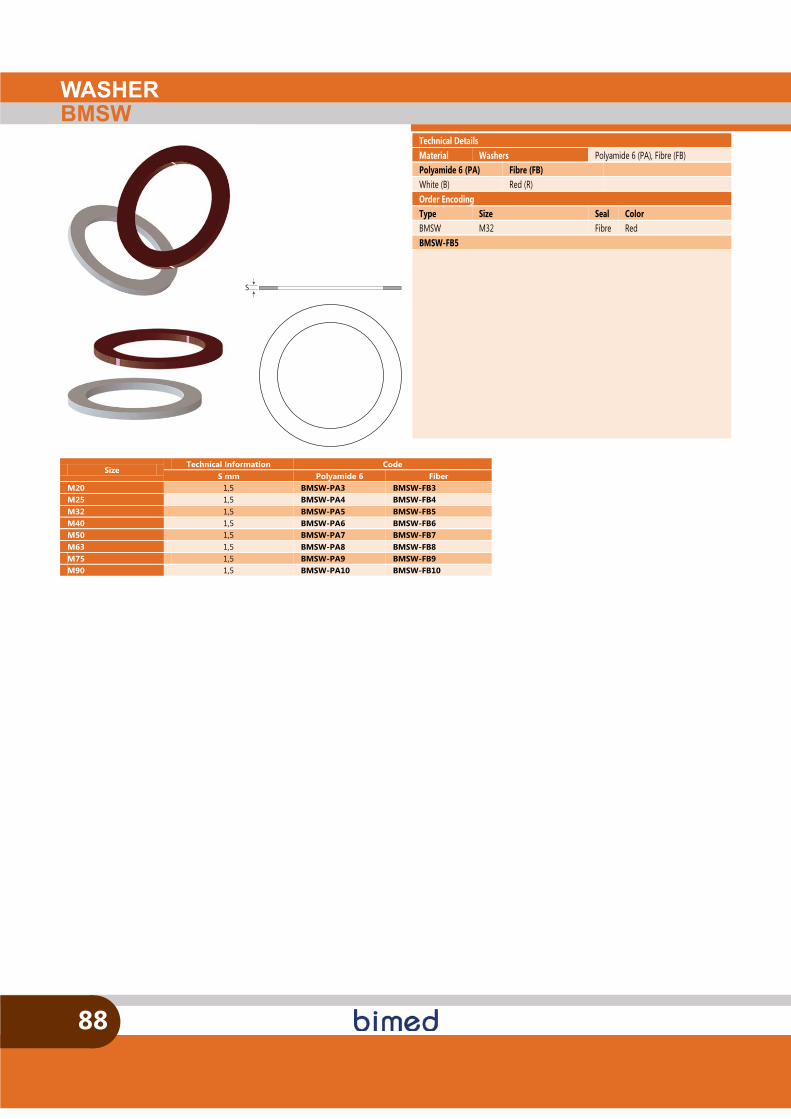
WASHERBMSW
88
Technical Details Material Washers Polyamide 6 (PA), Fibre (FB) Polyamide 6 (PA) Fibre (FB) White (B) Red (R) Order Encoding Type Size Seal Color BMSW M32 Fibre Red BMSW-FB5
Size Technical Information Code
S mm Polyamide 6 Fiber M20 1,5 BMSW-PA3 BMSW-FB3 M25 1,5 BMSW-PA4 BMSW-FB4 M32 1,5 BMSW-PA5 BMSW-FB5 M40 1,5 BMSW-PA6 BMSW-FB6 M50 1,5 BMSW-PA7 BMSW-FB7 M63 1,5 BMSW-PA8 BMSW-FB8 M75 1,5 BMSW-PA9 BMSW-FB9 M90 1,5 BMSW-PA10 BMSW-FB10
S
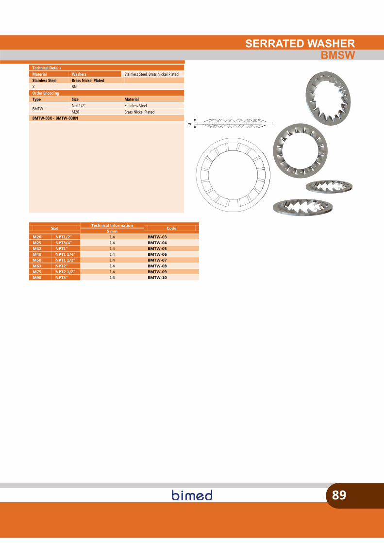
S
SERRATED WASHERBMSW
89
Technical Details Material Washers Stainless Steel, Brass Nickel Plated Stainless Steel Brass Nickel Plated X BN Order Encoding Type Size Material
BMTW Npt 1/2" Stainless Steel M20 Brass Nickel Plated
BMTW-03X - BMTW-03BN
Size Technical Information
Code S mm
M20 NPT1/2" 1,4 BMTW-03 M25 NPT3/4" 1,4 BMTW-04 M32 NPT1" 1,4 BMTW-05 M40 NPT1 1/4" 1,4 BMTW-06 M50 NPT1 1/2" 1,4 BMTW-07 M63 NPT2" 1,4 BMTW-08 M75 NPT2 1/2" 1,4 BMTW-09 M90 NPT3" 1,6 BMTW-10

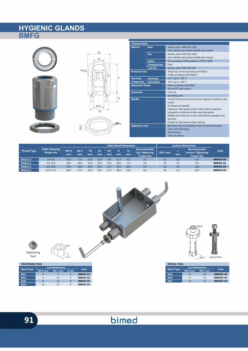
HYGIENIC GLANDSBMFG
91
h
SW C
SW B
SW L
e
TighteningTool
TIGHTENING TOOL
Gland Type Tool Dimensions
Code SW B mm SW C mm h mm
M12 5 7 5 BMFGT-01 M16 6 10 5 BMFGT-02 M20 8 13 8 BMFGT-03 M25 10 17 8 BMFGT-04
SPECIAL TOOL
Gland Type Tool Dimensions
Code SW B mm SW C mm
M16 6 10 BMFGST-02 M20 8 13 BMFGST-03 M25 10 17 BMFGST-04
SW B
SW C Special Tool
SP
Technical Details Material Body Stainless steel 1.4404 (AISI 316L)
other stainless steel grades available upon request Cap Stainless steel 1.4404 (AISI 316L)
other stainless steel grades available upon request Gasket TPE, according to FDA guideline 21 CFR 177.2600 Clamping Insert POM Lock Nut Stainless steel 1.4305 (AISI 303)
Protection Class IP 68 (5 bar, 30 min) according to EN 60529 IP 69K according to DIN 40050-9
Operating Temperature
Permanent -20 °C up to +100 °C Intermittent -40 °C up to +150 °C
Attachment Thread Metric, according to EN 60423 Pg and NPT upon request
Accessories Lock nuts Assembling tools
Benefits Smooth finish prevents harmful micro organisms to adhere to the surface. No threads are exposed. Cleaning of cable glands is easier, faster and less expensive compared to traditional stainless steel cable glands. Reliable strain relief due to strain relief element separated from grommet. Suitable for high pressure steam cleaning.
Application areas Manufacturing and packaging of food and pharmaceuticals. Clean room technology. Biotechnology. Chemical industry.
Thread Type Cable Clamping
Range mm
Cable Gland Dimensions Locknut Dimensions
Code SW A mm
SW C mm
TD mm
D1 mm
D2 mm
H mm
TL mm
Recommended Cap Tightening
Torque Nm SW L mm
e mm
Recommended Locknut Tightening
Torque Nm M12x1,5 3,0-6,5 14,0 7,0 12,0 15,6 6,8 21,5 6,0 2,5 15 3,3 6,0 BMFGX-0S M16x1,5 5,0-10,0 18,0 10,0 16,0 20,2 10,3 28,5 7,0 4,0 19 3,5 9,0 BMFGX-01 M20x1,5 6,0-12,0 22,0 13,0 20,0 24,1 12,3 33,0 10,0 5,0 24 3,5 12,0 BMFGX-02 M25x1,5 12,0-17,0 28,0 17,0 25,0 30,1 17,3 38,0 14,0 6,0 30 4,5 14,0 BMFGX-03
TD
H
TL
D1
SW A
D2
SW C
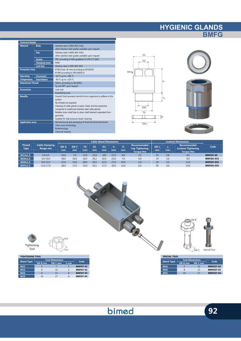
HYGIENIC GLANDSBMFG
92
TD
H
TL
D1
SW A
SWC
D2
SW L
e
Thread Type
Cable Clamping Range mm
Cable Gland Dimensions Locknut Dimensions
Code SW A mm
SW C mm
TD mm
D1 mm
D2 mm
H mm
TL mm
Recommended Cap Tightening
Torque Nm
SW L mm
e mm
Recommended Locknut Tightening
Torque Nm M12x1,5 3,0-6,5 14,0 7,0 12,0 15,6 6,8 21,5 6,0 2,5 15 2,8 6,0 BMFGX-0S M16x1,5 5,0-10,0 18,0 10,0 16,0 20,2 10,3 23,0 7,0 4,0 19 3,0 9,0 BMFGX-01S M20x1,5 6,0-12,0 22,0 13,0 20,0 24,1 12,3 27,0 10,0 5,0 24 3,5 12,0 BMFGX-02S M25x1,5 12,0-17,0 28,0 17,0 25,0 30,1 17,3 30,0 14,0 6,0 30 4,0 14,0 BMFGX-03S
h
SW C
SW B
TighteningTool
TIGHTENING TOOL
Gland Type Tool Dimensions
Code SW B mm SW C mm h mm
M12 5 7 5 BMFGT-01 M16 6 10 5 BMFGT-02 M20 8 13 8 BMFGT-03 M25 10 17 8 BMFGT-04
SPECIAL TOOL
Gland Type Tool Dimensions
Code SW B mm SW C mm
M16 6 10 BMFGST-02 M20 8 13 BMFGST-03 M25 10 17 BMFGST-04
SW B
SW C Special Tool
SP
Technical Details Material Body Stainless steel 1.4404 (AISI 316L)
other stainless steel grades available upon request Cap Stainless steel 1.4404 (AISI 316L)
other stainless steel grades available upon request Gasket TPE, according to FDA guideline 21 CFR 177.2600 Clamping Insert POM Lock Nut Stainless steel 1.4305 (AISI 303)
Protection Class IP 68 (5 bar, 30 min) according to EN 60529 IP 69K according to DIN 40050-9
Operating Temperature
Permanent -20 °C up to +100 °C Intermittent -40 °C up to +150 °C
Attachment Thread Metric, according to EN 60423 Pg and NPT upon request
Accessories Lock nuts Assembling tools
Benefits Smooth finish prevents harmful micro organisms to adhere to the surface. No threads are exposed. Cleaning of cable glands is easier, faster and less expensive compared to traditional stainless steel cable glands. Reliable strain relief due to strain relief element separated from grommet. Suitable for high pressure steam cleaning.
Application areas Manufacturing and packaging of food and pharmaceuticals. Clean room technology. Biotechnology. Chemical industry.
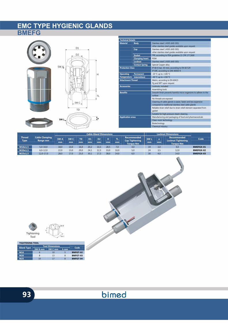
EMC TYPE HYGIENIC GLANDSBMEFG
93
h
SW C
SW B
TighteningTool
Thread Type
Cable Clamping Range mm
Cable Gland Dimensions Locknut Dimensions
Code SW A mm
SW C mm
TD mm
D1 mm
D2 mm
H mm
TL mm
Recommended Cap Tightening
Torque Nm
SW L mm
e mm
Recommended Locknut Tightening
Torque Nm M16x1,5 5,0-10,0 18,0 10,0 16,0 20,2 10,3 28,5 7,0 4,0 19 3,0 9,0 BMEFGX-01 M20x1,5 6,0-12,0 22,0 13,0 20,0 24,1 12,3 33,0 10,0 5,0 24 3,5 12,0 BMEFGX-02 M25x1,5 12,0-17,0 28,0 17,0 25,0 30,1 17,3 38,0 14,0 6,0 30 4,0 14,0 BMEFGX-03
Technical Details Material
Body Stainless steel 1.4305 (AISI 303) other stainless steel grades available upon request
Cap Stainless steel 1.4305 (AISI 303) other stainless steel grades available upon request
Gasket TPE, according to FDA guideline 21 CFR 177.2600 Clamping Insert POM Locknut Stainless steel 1.4305 (AISI 303) Contact Spring Special Copper alloy
Protection Class IP 68 (5 bar, 30 min), according to EN 60 529 IP 69K, according to DIN 40050-9
Operating Temperature
Permanent -20 °C up to +100 °C Intermittent -40 °C up to +150 °C
Attachment Thread Metric, according to EN 60423 Pg and NPT upon request
Accessories Locknuts, included Assembling tools
Benefits Smooth finish prevents harmful micro organisms to adhere to the surface No threads are exposed Cleaning of cable glands is easier, faster and less expensive compared to traditional stainless steel cable glands Reliable strain relief due to strain relief element separated from gasket Suitable for high pressure steam cleaning
Application areas Manufacturing and packaging of food and pharmaceuticals Clean room technology Biotechnology Chemical industry
TIGHTENING TOOL
Gland Type Tool Dimensions
Code SW B mm SW C mm h mm
M16 6 10 5 BMFGT-02 M20 8 13 8 BMFGT-03 M25 10 17 8 BMFGT-04
eSW L
TD
H
TL
D1
SW A
D2
SW C

HYGIENIC FITTINGSBMHF
SW T
T
94
TIGHTENING TOOL
Fitting Type Tool Dimensions
Ø T mm SW T mm M16 24 11 M20 27 14 M25 33 19 M32 42 25 M40 50 32 M50 58 36 M63 72 48
TD
H
TL
D
SW
d
Technical Details Material
Body Stainless steel 1.4404 (AISI 316L) other stainless steel grades available upon request
Cap Stainless steel 1.4404 (AISI 316L) other stainless steel grades available upon request
Gasket TPE, according to FDA guideline 21 CFR 177.2600 Ferrule Brass, Nickel plated
Protection Class IP 68 (5 bar, 30 min), according to EN 60 529 IP 69K, according to DIN 40050-9
Operating Temperature
Permanent -20 °C up to +100 °C Intermittent -40 °C up to +150 °C
Attachment Thread Metric, according to EN 60423 Pg and NPT upon request
Accessories Locknuts Benefits Smooth finish prevents harmful micro organisms to adhere to the
surface No threads are exposed Cleaning of fittings is easier, faster and less expensive compared to traditional stainless steel cable glands Suitable for high pressure steam cleaning
Application areas Manufacturing and packaging of food and pharmaceuticals Clean room technology Biotechnology Chemical industry
Thread Type
Fitting Dimensions Locknut Dimensions Code
Conduit Size H
mm TL
mm TD mm
D mm
d mm
SW mm
SW L mm
e mm
M16x1,5 M24x1,5/M16x1,5 36,8 11,5 16,0 17,2 12,0 27 19 3,0 BMHFX-01 M20x1,5 M27x1,5/M20x1,5 37,3 13,0 20,0 20,5 15,0 30 24 3,5 BMHFX-02 M25x1,5 M33x1,5/M25x1,5 42,4 15,0 25,0 25,8 20,0 36 30 4,0 BMHFX-03 M32x1,5 M42x1,5/M32x1,5 52,8 15,0 32,0 32,4 25,7 46 36 5,0 BMHFX-04 M40x1,5 M50x1,5/M40x1,5 58,9 16,0 40,0 41,2 34,2 54 46 5,0 BMHFX-05 M50x1,5 M58x2,0/M50x1,5 63,3 18,0 50,0 46,9 39,2 63 60 5,0 BMHFX-06 M63x1,5 M72x2,0/M63x1,5 68,6 20,0 63,0 59,0 50,0 77 70 6,0 BMHFX-07
SW L
e
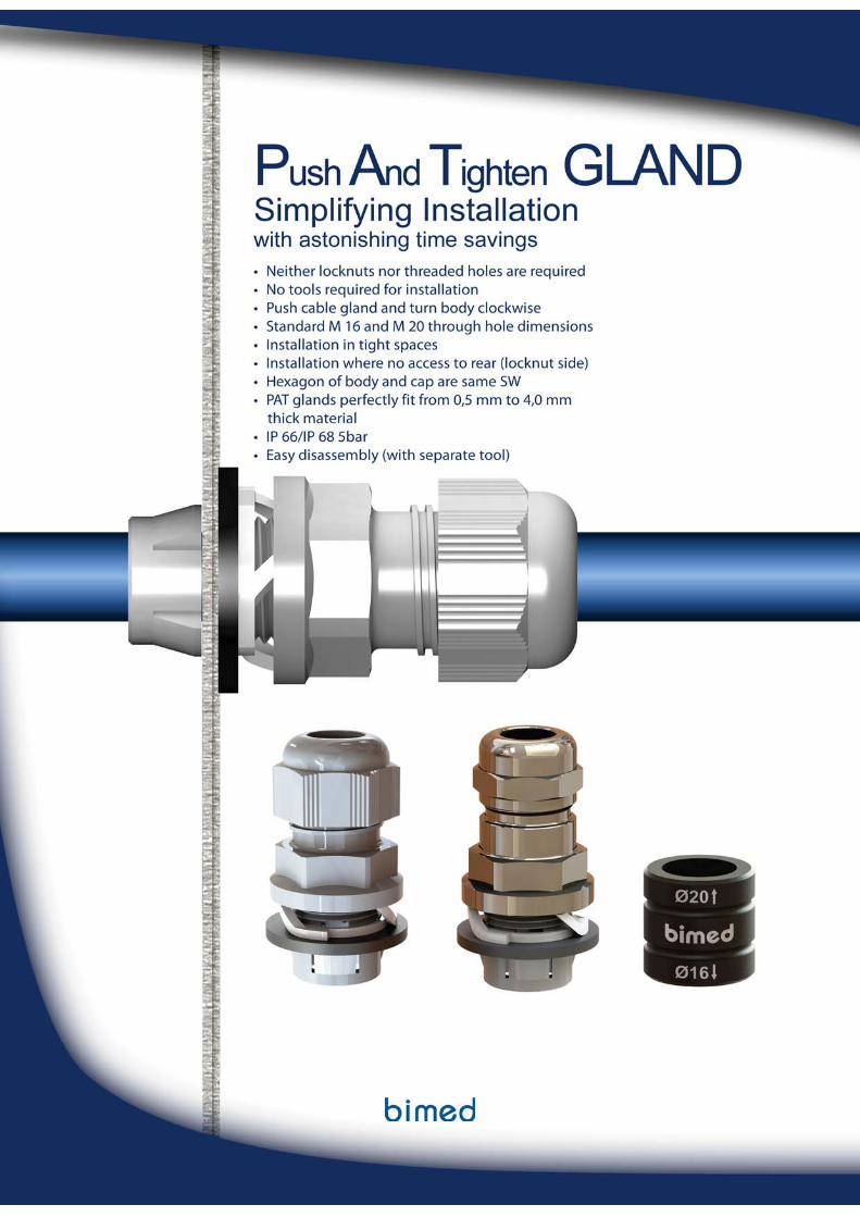
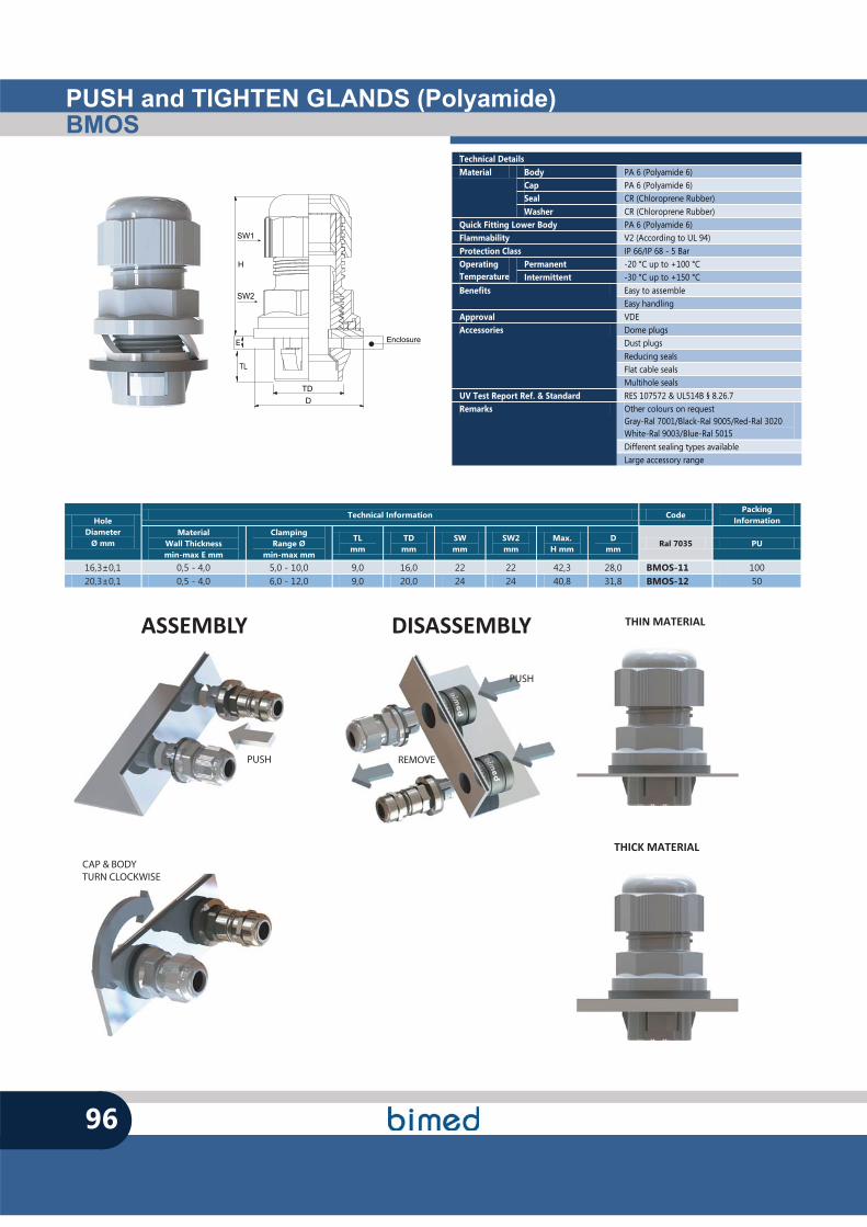
PUSH and TIGHTEN GLANDS (Polyamide)BMOS
96
TL
TD
H
D
E
SW1
SW2
Enclosure
Technical Details Material Body PA 6 (Polyamide 6)
Cap PA 6 (Polyamide 6) Seal CR (Chloroprene Rubber) Washer CR (Chloroprene Rubber)
Quick Fitting Lower Body PA 6 (Polyamide 6) Flammability V2 (According to UL 94) Protection Class IP 66/IP 68 - 5 Bar Operating Temperature
Permanent -20 °C up to +100 °C Intermittent -30 °C up to +150 °C
Benefits Easy to assemble Easy handling
Approval VDE Accessories Dome plugs
Dust plugs Reducing seals Flat cable seals Multihole seals
UV Test Report Ref. & Standard RES 107572 & UL514B § 8.26.7 Remarks Other colours on request
Gray-Ral 7001/Black-Ral 9005/Red-Ral 3020 White-Ral 9003/Blue-Ral 5015 Different sealing types available Large accessory range
Hole Diameter
Ø mm
Technical Information Code Packing
Information Material
Wall Thickness min-max E mm
Clamping Range Ø
min-max mm
TL mm
TD mm
SW mm
SW2 mm
Max. H mm
D mm
Ral 7035 PU
16,3±0,1 0,5 - 4,0 5,0 - 10,0 9,0 16,0 22 22 42,3 28,0 BMOS-11 100 20,3±0,1 0,5 - 4,0 6,0 - 12,0 9,0 20,0 24 24 40,8 31,8 BMOS-12 50
CAP & BODYTURN CLOCKWISE
PUSH
PUSH
REMOVE
ASSEMBLY DISASSEMBLY
THICK MATERIAL
THIN MATERIAL
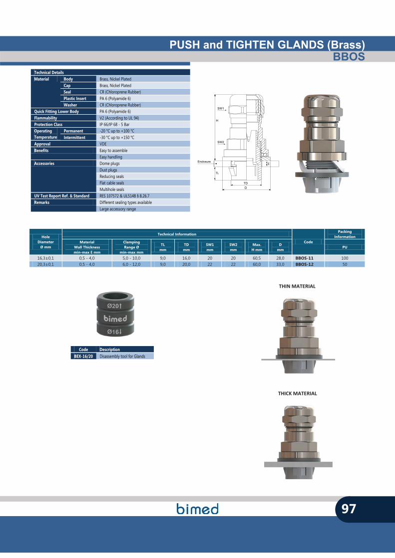
PUSH and TIGHTEN GLANDS (Brass)BBOS
97
Enclosure
H
SW1
SW2
TDD
TL
E
Technical Details Material Body Brass, Nickel Plated
Cap Brass, Nickel Plated Seal CR (Chloroprene Rubber) Plastic Insert PA 6 (Polyamide 6) Washer CR (Chloroprene Rubber)
Quick Fitting Lower Body PA 6 (Polyamide 6) Flammability V2 (According to UL 94) Protection Class IP 66/IP 68 - 5 Bar Operating Temperature
Permanent -20 °C up to +100 °C Intermittent -30 °C up to +150 °C
Approval VDE Benefits Easy to assemble
Easy handling Accessories Dome plugs
Dust plugs Reducing seals Flat cable seals Multihole seals
UV Test Report Ref. & Standard RES 107572 & UL514B § 8.26.7 Remarks Different sealing types available
Large accessory range
Hole Diameter
Ø mm
Technical Information
Code
Packing Information
Material Wall Thickness min-max E mm
Clamping Range Ø
min-max mm
TL mm
TD mm
SW1 mm
SW2 mm
Max. H mm
D mm
PU
16,3±0,1 0,5 - 4,0 5,0 - 10,0 9,0 16,0 20 20 60,5 28,0 BBOS-11 100 20,3±0,1 0,5 - 4,0 6,0 - 12,0 9,0 20,0 22 22 60,0 33,0 BBOS-12 50
Code Description BEX-16/20 Disassembly tool for Glands
THICK MATERIAL
THIN MATERIAL
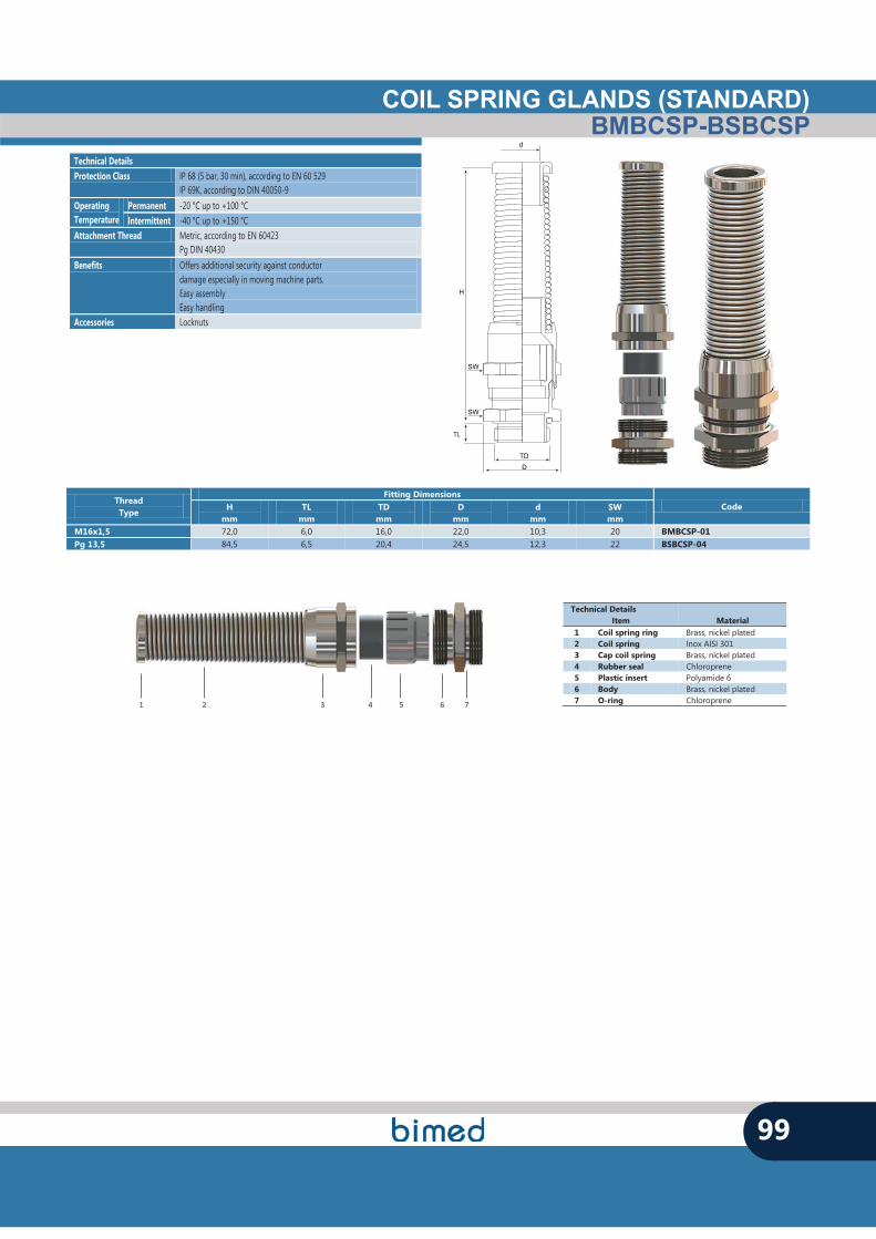
COIL SPRING GLANDS (STANDARD)BMBCSP-BSBCSP
99
Technical Details Protection Class IP 68 (5 bar, 30 min), according to EN 60 529
IP 69K, according to DIN 40050-9 Operating Temperature
Permanent -20 °C up to +100 °C Intermittent -40 °C up to +150 °C
Attachment Thread Metric, according to EN 60423 Pg DIN 40430
Benefits Offers additional security against conductor damage especially in moving machine parts. Easy assembly Easy handling
Accessories Locknuts
Thread Type
Fitting Dimensions Code H
mm TL
mm TD mm
D mm
d mm
SW mm
M16x1,5 72,0 6,0 16,0 22,0 10,3 20 BMBCSP-01 Pg 13,5 84,5 6,5 20,4 24,5 12,3 22 BSBCSP-04
Technical Details Item Material
1 Coil spring ring Brass, nickel plated 2 Coil spring Inox AISI 301 3 Cap coil spring Brass, nickel plated 4 Rubber seal Chloroprene 5 Plastic insert Polyamide 6 6 Body Brass, nickel plated 7 O-ring Chloroprene 1 2 3 4 5 6 7
H
SW
TD
D
TL
SW
d
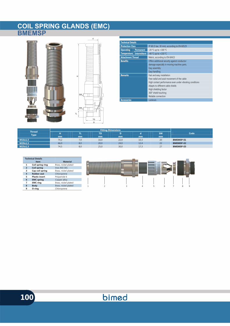
Technical Details Protection Class IP 68 (5 bar, 30 min), according to EN 60529 Operating Temperature
Permanent -20 °C up to +100 °C Intermittent -40 °C up to +150 °C
Attachment Thread Metric, according to EN 60423 Benefits Offers additional security against conductor
damage especially in moving machine parts. Easy assembly Easy handling
Remarks Fast and easy installation Free radial and axial movement of the cable High contact performance even under vibrating conditions Adapts to different cable shields High shielding factor 360° shield touching Reliable connection
Accessories Locknuts
COIL SPRING GLANDS (EMC)BMEMSP
100
Technical Details Item Material
1 Coil spring ring Brass, nickel plated 2 Coil spring Inox AISI 301 3 Cap coil spring Brass, nickel plated 4 Rubber seal Chloroprene 5 Plastic insert Polyamide 6 6 EMC spring Copper alloy 7 EMC ring Brass, nickel plated 8 Body Brass, nickel plated 9 O-ring Chloroprene
Thread Type
Fitting Dimensions Code H
mm TL
mm TD mm
D mm
d mm
SW mm
M16x1,5 74,2 7,0 16,0 22,0 10,3 20 BMEMSP-E1 M20x1,5 66,0 8,0 20,0 24,0 12,4 22 BMEMSP-E2 M25x1,5 74,5 8,0 25,0 30,0 17,3 27 BMEMSP-E3
1 2 3 4 5 6 7 8 9
H
SW
TD
D
TL
SW
d
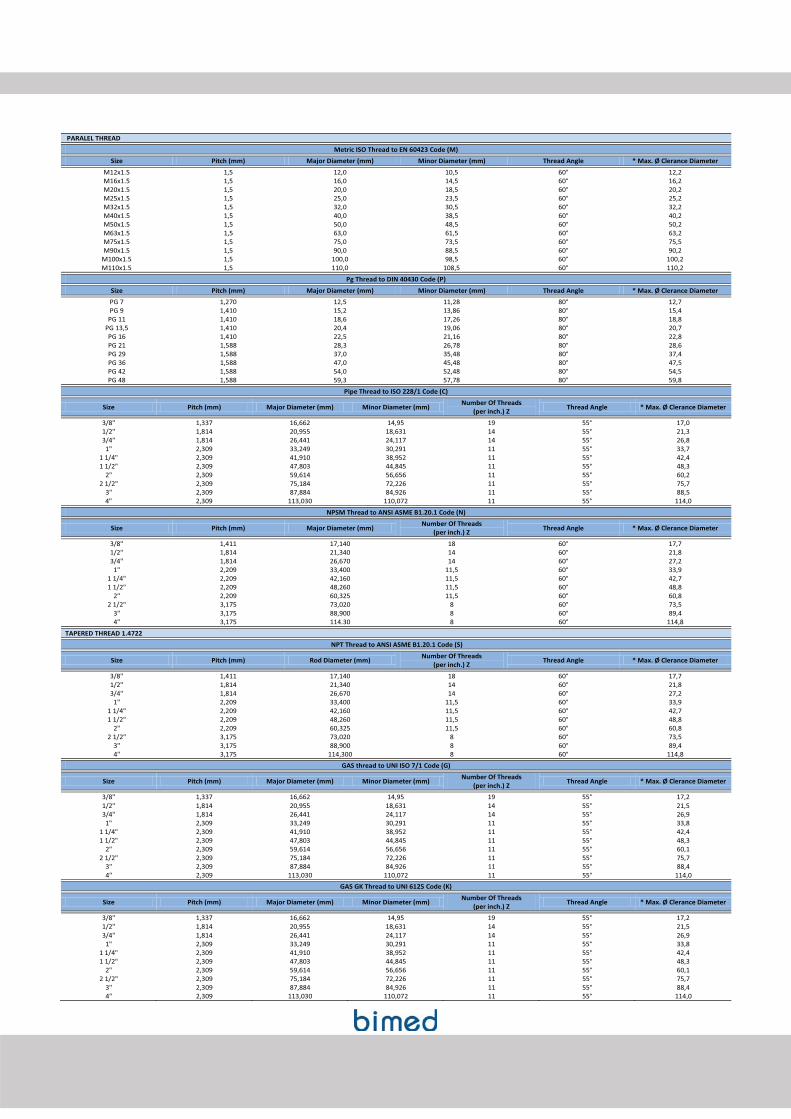
PARALEL THREAD
Metric ISO Thread to EN 60423 Code (M)
Size Pitch (mm) Major Diameter (mm) Minor Diameter (mm) Thread Angle * Max. Ø Clerance Diameter
M12x1.5 1,5 12,0 10,5 60° 12,2 M16x1.5 1,5 16,0 14,5 60° 16,2 M20x1.5 1,5 20,0 18,5 60° 20,2 M25x1.5 1,5 25,0 23,5 60° 25,2 M32x1.5 1,5 32,0 30,5 60° 32,2 M40x1.5 1,5 40,0 38,5 60° 40,2 M50x1.5 1,5 50,0 48,5 60° 50,2 M63x1.5 1,5 63,0 61,5 60° 63,2 M75x1.5 1,5 75,0 73,5 60° 75,5 M90x1.5 1,5 90,0 88,5 60° 90,2
M100x1.5 1,5 100,0 98,5 60° 100,2 M110x1.5 1,5 110,0 108,5 60° 110,2
Pg Thread to DIN 40430 Code (P)
Size Pitch (mm) Major Diameter (mm) Minor Diameter (mm) Thread Angle * Max. Ø Clerance Diameter
PG 7 1,270 12,5 11,28 80° 12,7 PG 9 1,410 15,2 13,86 80° 15,4
PG 11 1,410 18,6 17,26 80° 18,8 PG 13,5 1,410 20,4 19,06 80° 20,7 PG 16 1,410 22,5 21,16 80° 22,8 PG 21 1,588 28,3 26,78 80° 28,6 PG 29 1,588 37,0 35,48 80° 37,4 PG 36 1,588 47,0 45,48 80° 47,5 PG 42 1,588 54,0 52,48 80° 54,5 PG 48 1,588 59,3 57,78 80° 59,8
Pipe Thread to ISO 228/1 Code (C)
Size Pitch (mm) Major Diameter (mm) Minor Diameter (mm) Number Of Threads (per inch.) Z Thread Angle * Max. Ø Clerance Diameter
3/8" 1,337 16,662 14,95 19 55° 17,0 1/2" 1,814 20,955 18,631 14 55° 21,3 3/4" 1,814 26,441 24,117 14 55° 26,8 1" 2,309 33,249 30,291 11 55° 33,7
1 1/4" 2,309 41,910 38,952 11 55° 42,4 1 1/2" 2,309 47,803 44,845 11 55° 48,3
2" 2,309 59,614 56,656 11 55° 60,2 2 1/2" 2,309 75,184 72,226 11 55° 75,7
3" 2,309 87,884 84,926 11 55° 88,5 4" 2,309 113,030 110,072 11 55° 114,0
NPSM Thread to ANSI ASME B1.20.1 Code (N)
Size Pitch (mm) Major Diameter (mm) Number Of Threads (per inch.) Z Thread Angle * Max. Ø Clerance Diameter
3/8" 1,411 17,140 18 60° 17,7 1/2" 1,814 21,340 14 60° 21,8 3/4" 1,814 26,670 14 60° 27,2
1" 2,209 33,400 11,5 60° 33,9 1 1/4" 2,209 42,160 11,5 60° 42,7 1 1/2" 2,209 48,260 11,5 60° 48,8
2" 2,209 60,325 11,5 60° 60,8 2 1/2" 3,175 73,020 8 60° 73,5
3" 3,175 88,900 8 60° 89,4 4" 3,175 114.30 8 60° 114,8
TAPERED THREAD 1.4722
NPT Thread to ANSI ASME B1.20.1 Code (S)
Size Pitch (mm) Rod Diameter (mm) Number Of Threads (per inch.) Z Thread Angle * Max. Ø Clerance Diameter
3/8" 1,411 17,140 18 60° 17,7 1/2" 1,814 21,340 14 60° 21,8 3/4" 1,814 26,670 14 60° 27,2
1" 2,209 33,400 11,5 60° 33,9 1 1/4" 2,209 42,160 11,5 60° 42,7 1 1/2" 2,209 48,260 11,5 60° 48,8
2" 2,209 60,325 11,5 60° 60,8 2 1/2" 3,175 73,020 8 60° 73,5
3" 3,175 88,900 8 60° 89,4 4" 3,175 114,300 8 60° 114,8
GAS thread to UNI ISO 7/1 Code (G)
Size Pitch (mm) Major Diameter (mm) Minor Diameter (mm) Number Of Threads (per inch.) Z Thread Angle * Max. Ø Clerance Diameter
3/8" 1,337 16,662 14,95 19 55° 17,2 1/2" 1,814 20,955 18,631 14 55° 21,5 3/4" 1,814 26,441 24,117 14 55° 26,9 1" 2,309 33,249 30,291 11 55° 33,8
1 1/4" 2,309 41,910 38,952 11 55° 42,4 1 1/2" 2,309 47,803 44,845 11 55° 48,3
2" 2,309 59,614 56,656 11 55° 60,1 2 1/2" 2,309 75,184 72,226 11 55° 75,7
3" 2,309 87,884 84,926 11 55° 88,4 4" 2,309 113,030 110,072 11 55° 114,0
GAS GK Thread to UNI 6125 Code (K)
Size Pitch (mm) Major Diameter (mm) Minor Diameter (mm) Number Of Threads (per inch.) Z Thread Angle * Max. Ø Clerance Diameter
3/8" 1,337 16,662 14,95 19 55° 17,2 1/2" 1,814 20,955 18,631 14 55° 21,5 3/4" 1,814 26,441 24,117 14 55° 26,9 1" 2,309 33,249 30,291 11 55° 33,8
1 1/4" 2,309 41,910 38,952 11 55° 42,4 1 1/2" 2,309 47,803 44,845 11 55° 48,3
2" 2,309 59,614 56,656 11 55° 60,1 2 1/2" 2,309 75,184 72,226 11 55° 75,7
3" 2,309 87,884 84,926 11 55° 88,4 4" 2,309 113,030 110,072 11 55° 114,0