40
ABOVEGROUND TANK FABRICATION STANDARDS UL-142, UL-2085, UCL-S601

ABOVEGROUND TANK FABRICATION STANDARDS
UL-142, UL-2085, UCL-S601

KEY PURCHASING DECISIONS
Fuel to be Stored & Quantity
Tank Construction Specification
Underground or Aboveground
Tank Diameter and Length
Compartments
Fitting and Manway Requirements
Fabricator Proximity to Installation/Delivery

KEY PURCHASING DECISIONS
Regulatory Needs
Fire Code Compliance
Tank Geometry Vertical, Horizontal
Cylindrical, Rectangular
Determine type of Secondary Containment
Fire Protection Ratings
Support Design

STEEL SPECIFICATIONS
UL and STI standards specify steel requirements ASTM A 1011
ASTM A 36
Carbon Equivalency <0.53
Steel is purchased by fabricator in plate form or in coil form from steel mills or steel service centers

STEEL SPECIFICATION
Steel mills carefully control composition of steel
Carbon is added to iron to form steel. Addition of alloy and chemicals and the process in which it the steel is made gives the steel its desired properties.

STEEL SPECIFICATION
Carbon is kept below 0.3%. Higher carbon content adds strength but reduces weldability and formability.
Addition of manganese and silicon provide added strength.
Tank buyers depend upon the strength and ductility of steel

DESIRABLE PROPERTIES OF STEEL
Yield Strength
Tensile Strength
Flexural Strength
Ductility
Hardness
Resistance to Impact
Formed into any Shape and Size

UNDERWRITERS LABORATORIES
UL 142 “Steel Aboveground Tanks for Flammable and Combustible Liquids”
UL 2085 “Protected Aboveground Tanks for Flammable and Combustible Liquids”

Atmospheric Tank -0.5 to 1 psig
Single wall
Double wall
Steel Diked Tanks Open or Closed Top
Carbon or stainless steel
Stationary use only
UL 142ISBN 1-55989-385-0
Steel Aboveground Tanks forFlammable and CombustibleLiquids

UNDERWRITERS LABORATORIESUL 142
Capacities up to 75,000 gallons
Specifies steel thicknesses Primary tank
Secondary tank
Shells and heads

UL 142 STEEL THICKNESS

TANK HEADS
A machine will cold form the flange
The radius of the flange must be 2 times the thickness
The flange will be welded to the tank shell.

DOUBLE-WALL CONSTRUCTION
After the primary tank is built and tested, the outer wall is fabricated atop the primary tank.
The second wall is placed intimately atop the primary tank wall.

“A complete evaluation conducted on a limited quantity of representative tanks. These tests are intended to verify compliance with all applicable performance requirements in a standard.”
Support design test 2 times weight of another full tank
Ladder design test 1000 lb. static load at center of
longest rung
“A limited evaluation conducted on each tank prior to shipping. These tests are intended to verify compliance with production requirements in a standard, such as leakage.”
Air pressure test
Hydrostatic test
Performance Tests Production Tests

STI AST TECHNOLOGIES (UL 142)

UNDERWRITERS LABORATORIESUL 142
Horizontal Cylindrical Steel thickness specified, including shell and heads Optional support design requires testing or
calculations Diameters to 12 feet Air test at 5 psi

UNDERWRITERS LABORATORIESUL 142
Vertical cylindrical Steel thickness specified
Manufacturing air test at 1 ½ to 2 ½ psi
Dished or conical roof required

UL 142
Rectangular tanks Requires performance testing to
prove design at 15 psi
Manufacturing air test at 3 psi
18 Performance
18.1 Hydrostatic strength test
18.1.1 The tank shall be tested to demonstrate that the strength of the assembly and the welded joints are in accordance with these requirements.
18.1.2 The tank shall not rupture or leak when subjected to the Hydrostatic Strength Test, Section 40.
18.2 Top load test
18.2.1 After being subjected to the Top Load Test, Section 41, the tank shall then be subjected to the Leakage Test, Section 39, and shall not leak.

UL 142 SUPPORTS
Maximum height of 12 inches
Must withstand 2 times the weight of a full tank
Design using calculations approved by UL
Design using Performance Test

UL 142 LABEL
Will have one of these statements: Aboveground Tank for Flammable Liquids
Aboveground Tank for Flammable Liquids on Supports
Secondary Containment Aboveground Tank for Flammable Liquids
Open Top Diked Aboveground Tank for Flammable Liquids
Open Top Diked Secondary Containment Aboveground Tank for Flammable Liquids
Closed Top Diked Aboveground Tank for Flammable Liquids
Closed Top Diked Secondary Containment Aboveground Tank for Flammable Liquids
UL Serial No._________

“Protected Tank”
“Integral” Secondary containment Part of the construction of
the tank, monitorable
Insulation
Reduce heat in a fire
Protection from physical damage
UL 2085ISBN 0-7629-0238-8
Protected Aboveground Tanks forFlammable and CombustibleLiquids

2 Hour
2000 Degree
Furnace

VEHICLE IMPACT RESISTANCE

BALLISTICS RESISTANCE
150 grain M-2 ball ammunition
Muzzle velocity of 2700 feet per second
.30 caliber rifle
Distance of 100 feet

UL 2085 TANK CONSTRUCTION
Refer to UL 142 Steel thickness
Welding
Support design
Vents
Emergency vents
Must have provisions for monitoring interstitial space

FIREGUARD®

INSULATION IS PUMPED INTO SPACE BETWEEN PRIMARY AND SECONDARY

CLOSE-UP OF INSULATION
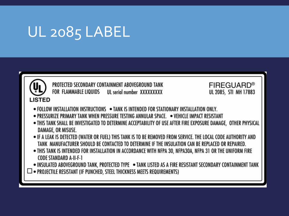
UL 2085 LABEL

GENERATOR BASE TANK

UL LISTED GENERATOR BASE TANK

UL LISTED GENERATOR BASE TANK TESTING

QUALITY CONTROL
Tank fabricators perform elaborate quality assurance to verify compliance with construction standards and customer specifications.
A visual inspection of the weld is always performed by multiple parties.

PRODUCTION TIGHTNESS PERFORMANCE TEST
All atmospheric tanks are tested with air pressure.
Horizontal cylindrical tanks are tested at 5 psi.
Vertical tanks at 3 psi.
Rectangular tanks are tested at a pressure based on its UL performance test, normally 3 -5 psi.

LOCATING PINHOLES
All welds are further tested during the pressure test with a soapsuds solution.
If the weld has a pinhole, air will escape at the pinhole and a bubble is easily seen
Welds must be repaired and proven tight.

PRODUCTION INTERSTICE TIGHTNESS PERFORMANCE TEST
Upon completion of production testing of the interstice with positive air pressure and soap testing the welds of the secondary containment, all air is released.
Then a vacuum is pulled within the interstice and monitored by the fabricator for tightness over time.

PREPARING THE TANK FOR DELIVERY
After ancillary equipment installed, coatings applied, etc. the tank is made ready for shipment.
Fabricators apply a vacuum into the interstice of secondary containment tanks

INTERSTITIAL VACUUM
After the vacuum is applied, the tank is held in storage until it is made ready for delivery
The vacuum remains on the tank during storage, delivery, and during much of the installation.
An easy view of the vacuum gauge to verify retention of the vacuum assures that both walls remain tight.

DOUBLE WALL VACUUM MONITORED TANKS – ULC-S601
Vacuum monitored tanks are constructed to maintain a Vacuum for their lifespan.
Vacuum is pulled to 24 inHg
Corrosion between tank wall is highly reduced due to the lack of atmosphere.
The Vacuum has an insulating factor, which helps to reduce tank condensation.
Vacuum monitored tanks can be equipped with a transducer allowing hookup with any monitoring systems.
Regular tank tank inspections can be as easy as viewing the Vacuum Gauge.

DOUBLE WALL VACUUM MONITORED TANKS – ULC-S601


![[Oil]aboveground oil storage tanks 2009](https://static.documents.pub/doc/80x56/55a50ed41a28abda588b48e1/oilaboveground-oil-storage-tanks-2009.jpg)


