Abrasive-water-jet blind-machining of polymer matrix composite materials F. Cénac 1,2 , F. Collombet 1 , R. Zitoune 1 and M. Déléris 2 1 Université de Toulouse ; INSA, UPS ; LGMT (Laboratoire de Génie Mécanique de Toulouse); 133, avenue de Rangueil, F-31077 Toulouse, France 2 JEDO Technologies, BP 78204, 31682 Labège cedex, France [email protected], [email protected]ABSTRACT The Abrasive Water jet Technology (AWJT) is currently widely used for cutting composite materials. The present paper evaluates its capability to blind-machine composites without damaging the part. A Doehlert’s experimental design is used to evaluate the AWJT capability domain for composite-material scan blind-machining. Within this domain, a common average-depth forecasting-model is evaluated and improved in order to develop rules concerning the process. It appears that the capability domain is mainly limited by the water wear energy which leads to delamination whereas the abrasive particle wear-energy machines without any damage. The domain is also governed by the material characteristics (ply thickness, heterogeneity…). The evolved average-depth forecasting-models allow to confirm several assumptions: The material may be introduced in the model within a single proportional constant (named “workability” for cutting applications). Moreover, the standoff distance appears to not be significant for scan blind-machining. By adding the fact that the AWJT machines a depth for the upper surface and not a dimension from a reference, the AWJT is very convenient for machining composite-material ply-per-ply even if the part is bent. 1. INTRODUCTION The abrasive water jet technology (AWJT) appears to be convenient for composite part machining, by completing the cutting tool capabilities. Indeed, it leads to low induced force and temperature on the material which is particularly adequate for machining those brittle-ductile multi-materials. Different research programs [1, 2] and many industrial observances demonstrate the pertinence of such technological association for cutting applications. But is it possible to use the AWJT not only for cutting composites but also for machining, or more precisely to industrially blind-machine composites. Unlike with cutting tools [3], composite material parts may be machined with AWJT ply per ply, without induced damages and untimely tool wear. Few studies already investigated this new field [4], but the only one that deals with composites [5] mostly details the machining technology but poorly define the influence of the material on the result. The paper aims at defining the abrasive water jet blind machining of composite materials. Relating physical considerations to experimental studies, the general capability domain of the technology will be explained in relation with the composite material specificities. A common forecasting model will be identified and evaluated. Finally, the key points concerning the composite-material AWJ blind-machining will be established. 1. MACHINING COMPOSITES WITH ABRASIVE WATER JET Because of their specificities, long-fiber composites materials should not be machined or drilled but at least just trimmed. If they are sometime machined, it is mostly because
Transcript
Abrasive-water-jet blind-machining of polymer matrix composite materials
F. Cénac1,2, F. Collombet1, R. Zitoune1 and M. Déléris2
1 Université de Toulouse ; INSA, UPS ; LGMT (Laboratoire de Génie Mécanique de Toulouse); 133, avenue de Rangueil, F-31077 Toulouse, France
The Abrasive Water jet Technology (AWJT) is currently widely used for cutting composite materials. The present paper evaluates its capability to blind-machine composites without damaging the part. A Doehlert’s experimental design is used to evaluate the AWJT capability domain for composite-material scan blind-machining. Within this domain, a common average-depth forecasting-model is evaluated and improved in order to develop rules concerning the process.
It appears that the capability domain is mainly limited by the water wear energy which leads to delamination whereas the abrasive particle wear-energy machines without any damage. The domain is also governed by the material characteristics (ply thickness, heterogeneity…).
The evolved average-depth forecasting-models allow to confirm several assumptions: The material may be introduced in the model within a single proportional constant (named “workability” for cutting applications). Moreover, the standoff distance appears to not be significant for scan blind-machining. By adding the fact that the AWJT machines a depth for the upper surface and not a dimension from a reference, the AWJT is very convenient for machining composite-material ply-per-ply even if the part is bent.
1. INTRODUCTION
The abrasive water jet technology (AWJT) appears to be convenient for composite part machining, by completing the cutting tool capabilities. Indeed, it leads to low induced force and temperature on the material which is particularly adequate for machining those brittle-ductile multi-materials. Different research programs [1, 2] and many industrial observances demonstrate the pertinence of such technological association for cutting applications. But is it possible to use the AWJT not only for cutting composites but also for machining, or more precisely to industrially blind-machine composites. Unlike with cutting tools [3], composite material parts may be machined with AWJT ply per ply, without induced damages and untimely tool wear.
Few studies already investigated this new field [4], but the only one that deals with composites [5] mostly details the machining technology but poorly define the influence of the material on the result.
The paper aims at defining the abrasive water jet blind machining of composite materials. Relating physical considerations to experimental studies, the general capability domain of the technology will be explained in relation with the composite material specificities. A common forecasting model will be identified and evaluated. Finally, the key points concerning the composite-material AWJ blind-machining will be established.
1. MACHINING COMPOSITES WITH ABRASIVE WATER JET Because of their specificities, long-fiber composites materials should not be machined or drilled but at least just trimmed. If they are sometime machined, it is mostly because
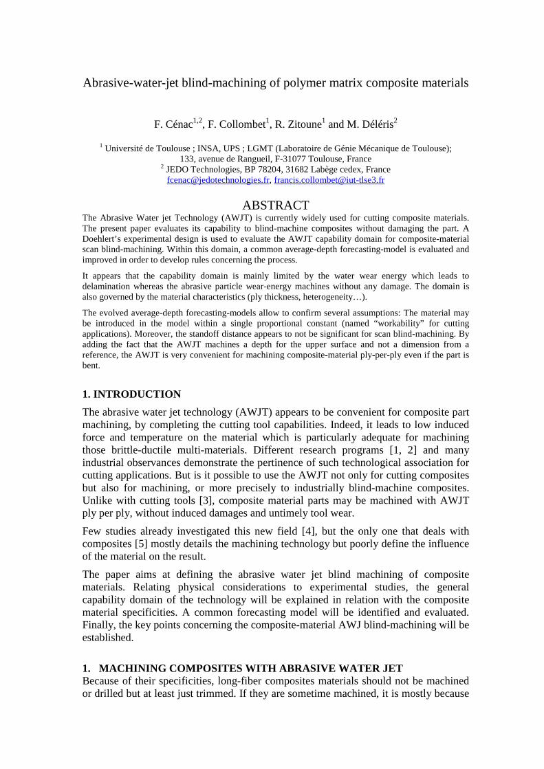
adapted design-and-manufacturing-tools have not been find out yet; so that in many situations, composite parts are integrated like metallic ones. But for many applications, like repairing, composite components still have to be machined and tailored processes have to be defined and certified. As long as the AWJT fits the composite cutting requirements, it may also be used to “blind-machine”. The abrasive water jet may be considered as wear energy beam which is driven to the part. The machining results in the way the component accumulate the energy. For cutting applications, the jet power is maximized and the feed rate is set so that the jet goes through the material. For machining, the energy has to be decreased by either decreasing the jet power or increasing the feed rate (to decrease the exposure time). Two kinds of blind machining have been described in literature: they may be called incision and scanning. The incision corresponds to a single pass for the low energy AWJ (Figure 1). It may be used for “blind-trimming” applications. Actually, the AWJT can not be used for many 3D-composite part trimming because if the part is completely cut, the jet risks to damage the material under the trimmed zone. The scanning corresponds in a succession of overlapping incisions and leads to surfacing or pockets (Figure 2).
Figure 1: AWJT incisions on quasi-isotropic M21T700 HexPLY (on the left) and on terra cotta (on the right). The two examples concern different machining settings.
2 m
m 10
mm
This paper focuses on the scanning process, defining rules concerning its capability domain (section 4.1). Within these “acceptable” settings, a common AWJ depth penetration forecast model used for cutting applications will be evaluated (section 4.2). 2. EXPERIMENTS In order to fulfill the current objectives concerning the AWJT scanning process, an experimental design based on Doehlert’s works (Figure 3) was performed. It concerned the four principal AWJT parameters that are present in the forecasting model. They are the pressure P (from 60 to 200 MPa), the feed rate f (from 1600 to 1900 mm/min), the standoff distance s (form 7 to 73 mm) and the abrasive particle mass flow rate Da (from 0 to 97 g/min). The 52 tests (for two 4-factor Doehlert-matrices) were applied to three composite materials respectively named:
- Carbon / epoxy HexPLY M21T700 GC with 20 plies and quasi isotropic stacking (manufactured in autoclave)
Referenced M21/35%/268/T700GC, this prepreg is manufactured by Hexcel Composites. It is autoclave cured. The M21 resin is a thermoset (i.e. epoxy) + thermoplastic matrix (both liquid and solid phase). The carbon fibers are the Toray T700GC
- Glass / epoxy HexFIT with a [0°/90°]4 stacking sequence (manufactured in autoclave) The Hexcel Film Infusion Technology (HexFIT), manufactured is based on the principle of Resin Film Infusion by altering twill/twill 2-2, which includes dry pre-impregnated layers covered by a resin film, with a 1 mm ply thickness.
- Glass / epoxy HexFIT with a [0°/90°]4 stacking sequence (manufactured in oven) The HexFIT was cured in autoclave and oven to evaluate the influence of the porosity.
Figure 2: Drawing of the scanning principle (on the left) and photo of a pocket machined on the carbone / epoxy M21T700GC (on the right)
2 mm
Figure 3: Graphical representation of the 3 The samples were performed using a common Flow Corp. AWJ cutting machine tool as it may be seen in Figure 4.As it should be noticed, the experiadvantage of the AWJT for composite applications: the machining force applied to the material is very low so that the part does not have to be hardly maintained.
Figure 4: AWJ scan blind machining of the Doehlert experimental design 3. MACHINING ANALYSISOnce the pockets were machined on the three materials (into two groups. The unacceptable pockets (because of the roughness or the presence of delamination) were used to identify the capability domain of the presented technology.
: Graphical representation of the 3-factor Doehlert experimental design
The samples were performed using a common Flow Corp. AWJ cutting machine tool as .
As it should be noticed, the experiments were simplified by one of the principle advantage of the AWJT for composite applications: the machining force applied to the material is very low so that the part does not have to be hardly maintained.
blind machining of the Doehlert experimental design
MACHINING ANALYSIS Once the pockets were machined on the three materials (Figure 5), they were divided
two groups. The unacceptable pockets (because of the roughness or the presence of delamination) were used to identify the capability domain of the presented technology.
X1
X2
X3
experimental design.
The samples were performed using a common Flow Corp. AWJ cutting machine tool as
ments were simplified by one of the principle advantage of the AWJT for composite applications: the machining force applied to the material is very low so that the part does not have to be hardly maintained.
blind machining of the Doehlert experimental design.
), they were divided two groups. The unacceptable pockets (because of the roughness or the presence of
delamination) were used to identify the capability domain of the presented technology.
Figure 5: AWJ machined pockets on the carbon / epoxy M21T700 GC (on the left) and on the Glass / epoxy HexFIT (on the right). The clean pockets were systematically measured with four reference points and twenty measure points. Actually, the composite material samples are not completely straight and a reference surface has to be computed for each pocket. After that stage, several Matlab programs automatically treat the results to crop the obtained depth characteristics (average, maximum, minimum values and the associated variance). 4. RESULTS From the experimental design, two kind of result were obtained: the first results concerned the AWJT capability domain for composite material blind-machining and the setting rules to respect. The second one concerned the appropriation of a common forecasting model used for cutting applications. Using the model, interesting observations were obtained concerning the specificities of such techniques.
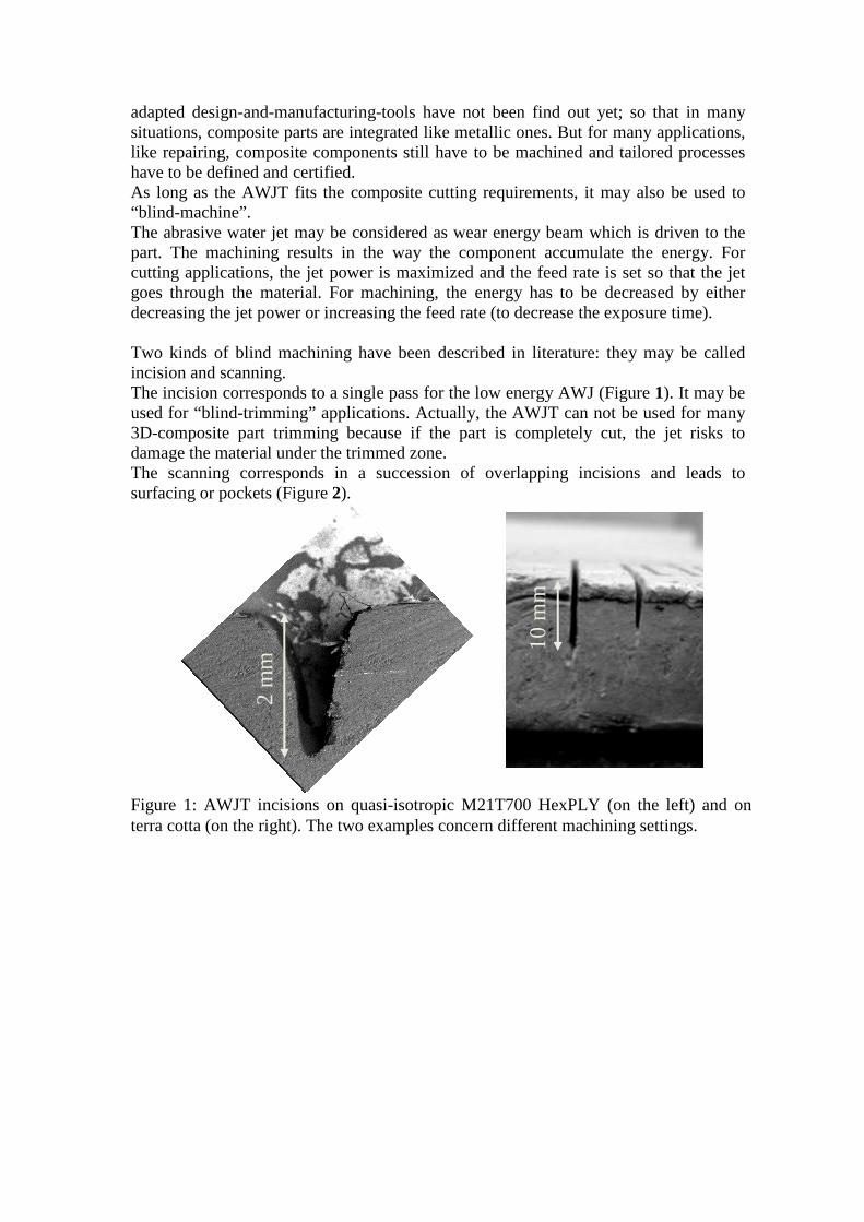
4.1. CAPABILITY DOMAIN The main limits of the capability domain are led by the delamination process that may occur in two cases: when the jet first impacts the part and if the water contributes to the wear phenomenon. At this stage, it is important to explain the physics and the technology of the AWJ [6]: As it is represented in Figure 6, the energy is provided by pressurized water. Going through the orifice, a hypersonic jet is created and sucks the abrasive particles as it diverges, using a Venturi effect. Then, the sand is accelerated in the focusing tube as the water momentum decreases. In the final jet, both abrasive and water own machining energy and each one leads to a specific wear mechanism.
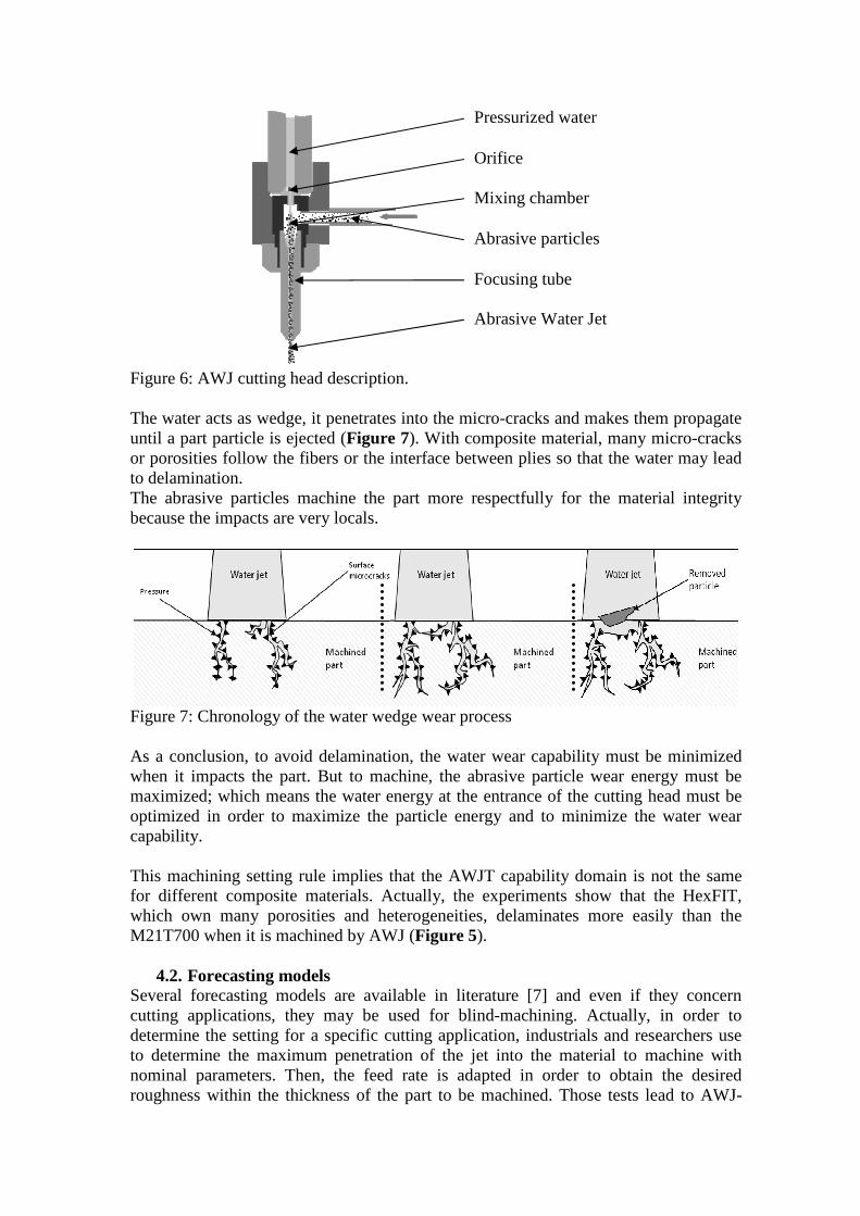
Figure 6: AWJ cutting head description. The water acts as wedge, it penetrates into the micro-cracks and makes them propagate until a part particle is ejected (Figure 7). With composite material, many micro-cracks or porosities follow the fibers or the interface between plies so that the water may lead to delamination. The abrasive particles machine the part more respectfully for the material integrity because the impacts are very locals.
Figure 7: Chronology of the water wedge wear process As a conclusion, to avoid delamination, the water wear capability must be minimized when it impacts the part. But to machine, the abrasive particle wear energy must be maximized; which means the water energy at the entrance of the cutting head must be optimized in order to maximize the particle energy and to minimize the water wear capability. This machining setting rule implies that the AWJT capability domain is not the same for different composite materials. Actually, the experiments show that the HexFIT, which own many porosities and heterogeneities, delaminates more easily than the M21T700 when it is machined by AWJ (Figure 5).
4.2. Forecasting models Several forecasting models are available in literature [7] and even if they concern cutting applications, they may be used for blind-machining. Actually, in order to determine the setting for a specific cutting application, industrials and researchers use to determine the maximum penetration of the jet into the material to machine with nominal parameters. Then, the feed rate is adapted in order to obtain the desired roughness within the thickness of the part to be machined. Those tests lead to AWJ-
Pressurized water
Orifice
Mixing chamber
Abrasive particles
Focusing tube
Abrasive Water Jet
incisions and for this reason may be adapted and identified to forecast scan blindmachining average depth. The most common model (standoff distance (s) and the abrasive masse flow rate (Dmachined depth (h). It requires five identification constants (a
321 ....0aaa DsfPah =
From this model (1), and in accordance with the experimental observations, many assumptions were made to define new models simpler or more accuratewill be presented further in order to evaluate the different assumptions. Concerning the first assumptionthe average machined depths measured for the three materials is almost constant. This observation leads to just introduce the material specificities into the first constant aThis constant a0, is often used for cutting applications and names “[7].
Figure 8: Average machined depth (mm) for For a second test model, it may be assumed that during a blind machining, a fraction of the jet energy is not used and is lost for the process. A first order of the jet energy is proportional with the water pressure. This threshold pressure (Pth) to penalize the result (2).
( ) 1..0aa
th fPPah −= A third test model (3) consisted in Actually, Looking at the machining results, it appears a significant influence on the average machined depth (within certain limitsbetween 32 and 73 mm).
421 ...0aa
aa DfPah =
eason may be adapted and identified to forecast scan blind
The most common model (1) implies the water pressure (P), the feed rate (f), the standoff distance (s) and the abrasive masse flow rate (Da) to compute the average machined depth (h). It requires five identification constants (a0…a4).
4aaD (1)
, and in accordance with the experimental observations, many to define new models simpler or more accurate
will be presented further in order to evaluate the different assumptions.
first assumption, the Figure 8 shows that the relative difference between the average machined depths measured for the three materials is almost constant. This
to just introduce the material specificities into the first constant a, is often used for cutting applications and names “material
: Average machined depth (mm) for the twenty-six "clean" pockets.
, it may be assumed that during a blind machining, a fraction of the jet energy is not used and is lost for the process. A first order of the jet energy is proportional with the water pressure. This observation leads to the introduction of a
) to penalize the result (2).
432 .. aa
aa Ds (2)
consisted in removing the standoff distance from the model. at the machining results, it appears that this parameter does not have
a significant influence on the average machined depth (within certain limits
(3)
eason may be adapted and identified to forecast scan blind-
implies the water pressure (P), the feed rate (f), the ) to compute the average
, and in accordance with the experimental observations, many to define new models simpler or more accurate. A comparison
will be presented further in order to evaluate the different assumptions.
shows that the relative difference between the average machined depths measured for the three materials is almost constant. This
to just introduce the material specificities into the first constant a0. material workability”
six "clean" pockets.
, it may be assumed that during a blind machining, a fraction of the jet energy is not used and is lost for the process. A first order of the jet energy is
observation leads to the introduction of a
removing the standoff distance from the model. that this parameter does not have
a significant influence on the average machined depth (within certain limits situated
A last test model aimed at integrating the abrasive particle momentum into the model. This model principal interest is to introduce many parameters concerning the abrasive particles, the cutting head geometry and the air proportion, linking them by phenomenological equations. This part of the work was based on the Tazibt’s works [8] on the abrasive particle speed (va) and is given by the system of equation (5). It is based on the momentum conservation laws and the Newton’s laws. The system may be solved by digitization of the distance.
With �� and �� the density of the abrasive and the fluid, � and � the speed of the abrasive particles and the fluid, �� the fluid initial speed, ! the length of the mixing tube, "# the drag coefficient, �� the abrasive particle average diameter, $� � and $� � the mass flow rate of the abrasive and the fluid, and % a coefficient given by % � $� � $� �⁄ . The current main limit of this model is that the most of the parameters (the air proportion in the fluid, the particle drag coefficient, the initial fluid speed…) have to be identified by experiments. At this time, these critical values are taken from the literature.
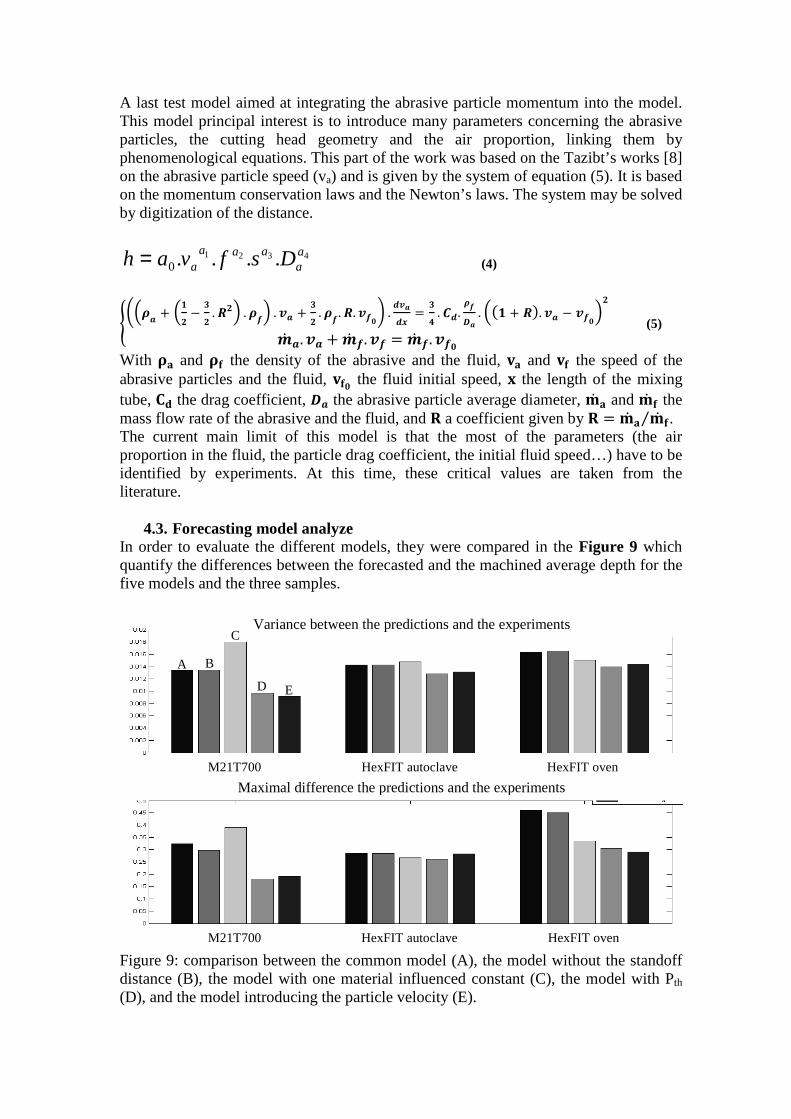
4.3. Forecasting model analyze In order to evaluate the different models, they were compared in the Figure 9 which quantify the differences between the forecasted and the machined average depth for the five models and the three samples.
Figure 9: comparison between the common model (A), the model without the standoff distance (B), the model with one material influenced constant (C), the model with Pth (D), and the model introducing the particle velocity (E).
M21T700 HexFIT autoclave HexFIT oven
Maximal difference the predictions and the experiments
M21T700 HexFIT autoclave HexFIT oven
A B
D E
Variance between the predictions and the experiments C
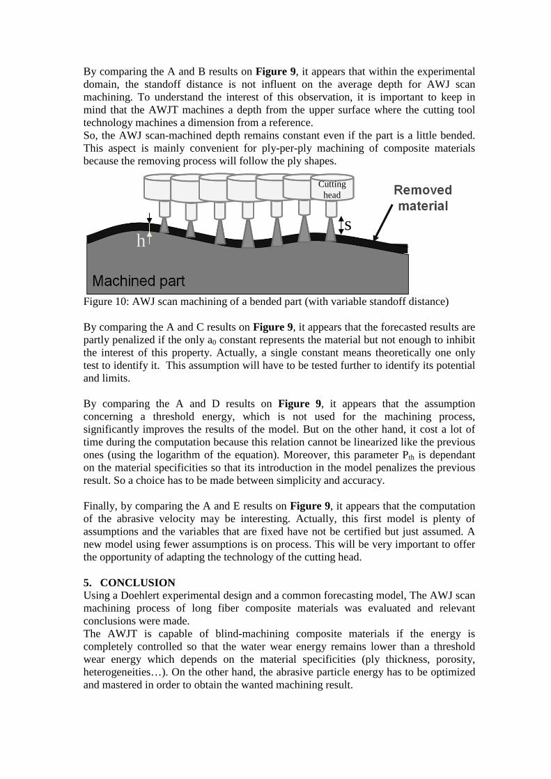
By comparing the A and B results on Figure 9, it appears that within the experimental domain, the standoff distance is not influent on the average depth for AWJ scan machining. To understand the interest of this observation, it is important to keep in mind that the AWJT machines a depth from the upper surface where the cutting tool technology machines a dimension from a reference. So, the AWJ scan-machined depth remains constant even if the part is a little bended. This aspect is mainly convenient for ply-per-ply machining of composite materials because the removing process will follow the ply shapes.
Figure 10: AWJ scan machining of a bended part (with variable standoff distance) By comparing the A and C results on Figure 9, it appears that the forecasted results are partly penalized if the only a0 constant represents the material but not enough to inhibit the interest of this property. Actually, a single constant means theoretically one only test to identify it. This assumption will have to be tested further to identify its potential and limits. By comparing the A and D results on Figure 9, it appears that the assumption concerning a threshold energy, which is not used for the machining process, significantly improves the results of the model. But on the other hand, it cost a lot of time during the computation because this relation cannot be linearized like the previous ones (using the logarithm of the equation). Moreover, this parameter Pth is dependant on the material specificities so that its introduction in the model penalizes the previous result. So a choice has to be made between simplicity and accuracy. Finally, by comparing the A and E results on Figure 9, it appears that the computation of the abrasive velocity may be interesting. Actually, this first model is plenty of assumptions and the variables that are fixed have not be certified but just assumed. A new model using fewer assumptions is on process. This will be very important to offer the opportunity of adapting the technology of the cutting head. 5. CONCLUSION Using a Doehlert experimental design and a common forecasting model, The AWJ scan machining process of long fiber composite materials was evaluated and relevant conclusions were made. The AWJT is capable of blind-machining composite materials if the energy is completely controlled so that the water wear energy remains lower than a threshold wear energy which depends on the material specificities (ply thickness, porosity, heterogeneities…). On the other hand, the abrasive particle energy has to be optimized and mastered in order to obtain the wanted machining result.
Cutting head
s h
As long as the capability domain of the machined part is respected, the forecasting model is easy to identify according to the material specificities which will mostly be influent on the machined roughness and dimensional tolerance. The abrasive water jet technology appears to be very convenient for machining ply-per-ply composite materials because it leads to constant depth even with bended parts. These experiments were the first stage of a long term study which has now to pass through the model improvement, and the machining of much more composite materials in order to accurately define the capability domain (with SEM observations, optical fiber Bragg grating and mechanical tests). This current study aims also at computing new models to forecast the roughness and dimensional tolerance. ACKNOWLEDGEMENTS The work presented in this paper has been funded in part by the DRIRE and the Préfecture de Midi-Pyrénées as an EPICEA Project. REFERENCES
1- Wang J., “Abrasive Waterjet Machining of Polymer Matrix Composites”. International Journal of Advanced Machining Technology, Vol. 15, pp 757-768, 1999
2- Hashish M., Status and potential of waterjet machining of composites, Proceedings of 10th American Waterjet Conference, Huston, Texas, paper 64, 1999.
3- Zitoune R., Collombet F., Lachaux F., Piquet R. and Pasquet P., “Experiment-calculation comparison of the cutting conditions representative of the long fibre composite drilling phase”, Composites Science and Technology, March 2005, Issue 3-4, Vol. 65. pp. 455-466.
4- Paul S., Hoogstrate A.M., van Luttervelt C.A. and Kals H.J.J. “An experimental investigation of rectangular pocket milling with abrasive water jet”, Journal of Material Processing Technology, 1998; 73:179-188.
5- Dunsky C., Tacheron P. And Hashish M., “Waterjet techniques for composite-material jet engine component repair”, Naval Air Warfare Center, Phase 1 SBIR final report, June 1996.
6- Wang J., “Abrasive Waterjet Machining of Engineering Materials”, Material Science Foundations, 2003; vol. 19.
7- Momber A.W., Kovacevic R., “Principles of abrasive water jet machining”, Springer, 1998.
8- Tazibt A., Abriak N. And Parsy F., “Prediction of abrasive particle velocity in a high pressure water jet and effect of air on acceleration process”, European Journal of Mechanics, B/Fluids, 1996; vol. 15: n°4