2009 Saturn VUE - AWD | VUE, VUE Hybrid (VIN Z), Captiva Sport Service Manual | Brakes | Antilock Brake System | Repair Instructions | Document ID: 2165370
Antilock Brake System Automated Bleed Procedure Warning: Refer to Brake Fluid Irritant Warning in the Preface section.
Caution: Refer to Brake Fluid Effects on Paint and Electrical Components Caution in the Preface section.
Note: Before performing the antilock brake system (ABS) Automated Bleed Procedure, first perform a manual or pressure bleed of the base brake system. Refer to Hydraulic Brake System Bleeding. The automated bleed procedure is recommended when one of the following conditions exist:
The ABS Automated Bleed Procedure uses a scan tool to cycle the system solenoid valves and run the pump in order to purge any air from the secondary circuits. These circuits are normally closed off, and are only opened during system initialization at vehicle start up and during ABS operation. The automated bleed procedure opens these secondary circuits and allows any air trapped in these circuits to flow out toward the brake corners.
Automated Bleed Procedure
Caution: The Auto Bleed Procedure may be terminated at any time during the process by pressing the EXIT button. No further Scan Tool prompts pertaining to the Auto Bleed procedure will be given. After exiting the bleed procedure, relieve bleed pressure and disconnect bleed equipment per manufacturers instructions. Failure to properly relieve pressure may result in spilled brake fluid causing damage to components and painted surfaces.
1. Raise and support the vehicle. Refer to Lifting and Jacking the Vehicle. 2. Remove all 4 tire and wheel assemblies. Refer to Tire and Wheel Removal and Installation. 3. Inspect the brake system for leaks and visual damage. Refer to Symptoms - Hydraulic
Brakes. Repair or replace components as needed. 4. Lower the vehicle. 5. Inspect the battery state of charge. Refer to Battery Inspection/Test. 6. Install a scan tool. 7. Turn the ignition ON, with the engine OFF. 8. With the scan tool, establish communications with the ABS system. Select Special Functions.
Select Automated Bleed from the Special Functions menu. 9. Raise and support the vehicle. Refer to Lifting and Jacking the Vehicle.
10. Following the directions given on the scan tool, pressure bleed the base brake system. Refer to Hydraulic Brake System Bleeding.
11. Follow the scan tool directions until the desired brake pedal height is achieved. 12. If the bleed procedure is aborted, a malfunction exists. Perform the following steps before
resuming the bleed procedure:
• Base brake system bleeding does not achieve the desired pedal height or feel
• Extreme loss of brake fluid has occurred
• Air ingestion is suspected in the secondary circuits of the brake modulator assembly
• If a DTC is detected, refer to Diagnostic Trouble Code (DTC) List - Vehicle and diagnose the appropriate DTC.
• If the brake pedal feels spongy, perform the conventional brake bleed procedure again.
13. When the desired pedal height is achieved, press the brake pedal to inspect for firmness. 14. Lower the vehicle. 15. Remove the scan tool. 16. Install the tire and wheel assemblies. Refer to Tire and Wheel Removal and Installation. 17. Inspect the brake fluid level. Refer to Master Cylinder Reservoir Filling. 18. Road test the vehicle while inspecting that the pedal remains high and firm.
2009 Saturn VUE - AWD | VUE, VUE Hybrid (VIN Z), Captiva Sport Service Manual | Brakes | Antilock Brake System | Repair Instructions | Document ID: 1998897
Steering Angle Sensor Centering The steering angle sensor does not require centering often. Centering of the steering angle sensor might be required after certain service procedures are performed. Some of these procedures are as follows:
The steering angle sensor centering procedure can be completed with a scan tool using the following steps:
1. Using the steering wheel, align the front wheels forward. 2. Set the transmission in the PARK position. 3. Turn the ignition switch ON, with the engine OFF. 4. Clear any DTCs that may be set. 5. Select Steering Angle Sensor Centering in the EBCM Special Functions list. 6. Follow the scan tool directions to complete the centering procedure.
• Steering gear replacement
• Steering column replacement
• Steering angle sensor replacement
• Intermediate shaft replacement
• Electronic brake control module (EBCM) replacement
2009 Saturn VUE - AWD | VUE, VUE Hybrid (VIN Z), Captiva Sport Service Manual | Brakes | Antilock Brake System | Repair Instructions | Document ID: 2167671
Electronic Brake Control Module Replacement (Except Hybrid)
Removal Procedure
Warning: Refer to Brake Fluid Irritant Warning in the Preface section.
Caution: Refer to Brake Fluid Effects on Paint and Electrical Components Caution in the Preface section.
Caution: Always connect or disconnect the wiring harness connector from the EBCM/EBTCM with the ignition switch in the OFF position. Failure to observe this precaution could result in damage to the EBCM/EBTCM.
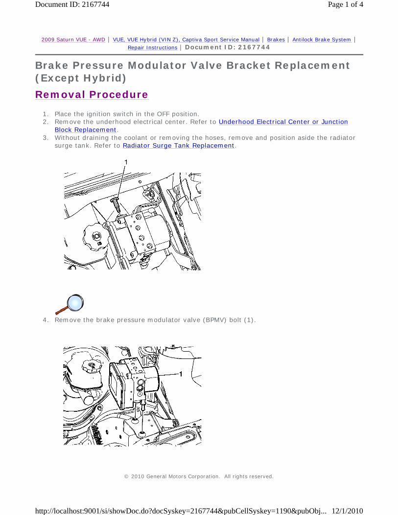
1. Place the ignition switch in the OFF position. 2. Remove the underhood electrical center. Refer to Underhood Electrical Center or Junction
Block Replacement. 3. Without draining the coolant or removing the hoses, remove and position aside the radiator
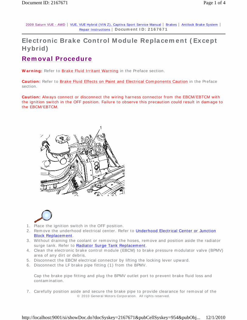
surge tank. Refer to Radiator Surge Tank Replacement. 4. Clean the electronic brake control module (EBCM) to brake pressure modulator valve (BPMV)
area of any dirt or debris. 5. Disconnect the EBCM electrical connector by lifting the locking lever upward. 6. Disconnect the LF brake pipe fitting (1) from the BPMV.
Cap the brake pipe fitting and plug the BPMV outlet port to prevent brake fluid loss and contamination.
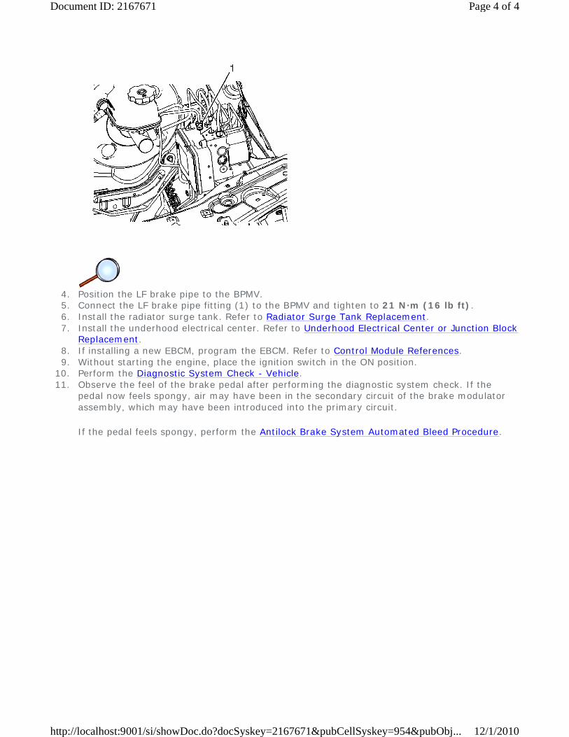
4. Position the LF brake pipe to the BPMV. 5. Connect the LF brake pipe fitting (1) to the BPMV and tighten to 21 N·m (16 lb ft). 6. Install the radiator surge tank. Refer to Radiator Surge Tank Replacement. 7. Install the underhood electrical center. Refer to Underhood Electrical Center or Junction Block
Replacement. 8. If installing a new EBCM, program the EBCM. Refer to Control Module References. 9. Without starting the engine, place the ignition switch in the ON position.
10. Perform the Diagnostic System Check - Vehicle. 11. Observe the feel of the brake pedal after performing the diagnostic system check. If the
pedal now feels spongy, air may have been in the secondary circuit of the brake modulator assembly, which may have been introduced into the primary circuit.
If the pedal feels spongy, perform the Antilock Brake System Automated Bleed Procedure.
Warning: Refer to Brake Fluid Irritant Warning in the Preface section.
Caution: Refer to Brake Fluid Effects on Paint and Electrical Components Caution in the Preface section.
Caution: Always connect or disconnect the wiring harness connector from the EBCM/EBTCM with the ignition switch in the OFF position. Failure to observe this precaution could result in damage to the EBCM/EBTCM.
1. Turn the ignition switch to the OFF position. 2. Remove the underhood electrical center. Refer to Underhood Electrical Center or Junction
Block Replacement. 3. Without draining the coolant or removing the hoses, remove and position aside the radiator
surge tank. Refer to Radiator Surge Tank Replacement.
4. Disconnect the electronic brake control module (EBCM) electrical connector by lifting the
locking tabs. 5. Disconnect the LF brake pipe fitting (1) at the brake pressure modulator valve (BPMV).
Cap the brake pipe fitting and plug the BPMV outlet port to prevent brake fluid loss and contamination.
6. Disconnect the RF brake pipe fitting (2) from the BPMV.
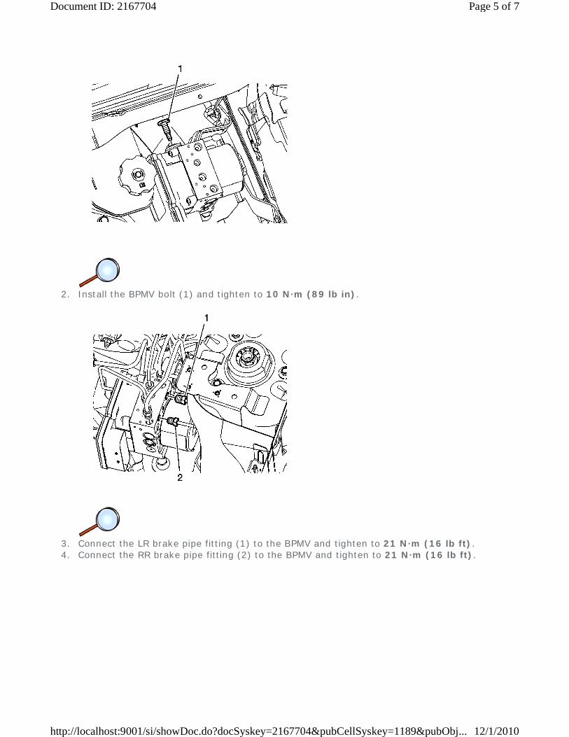
2. Install the BPMV bolt (1) and tighten to 10 N·m (89 lb in).
3. Connect the LR brake pipe fitting (1) to the BPMV and tighten to 21 N·m (16 lb ft). 4. Connect the RR brake pipe fitting (2) to the BPMV and tighten to 21 N·m (16 lb ft).
5. Connect the master cylinder primary brake pipe fitting (1) to the BPMV and tighten to
21 N·m (16 lb ft). 6. Connect the master cylinder secondary brake pipe fitting (2) to the BPMV and tighten to
21 N·m (16 lb ft).
7. Connect the LF brake pipe fitting (1) to the BPMV and tighten to 21 N·m (16 lb ft). 8. Connect the RF brake pipe fitting (2) to the BPMV and tighten to 21 N·m (16 lb ft). 9. Connect the EBCM electrical connector.
10. Install the radiator surge tank. Refer to Radiator Surge Tank Replacement. 11. Install the underhood electrical center. Refer to Underhood Electrical Center or Junction Block
Replacement. 12. Bleed the hydraulic brake system. Refer to Hydraulic Brake System Bleeding. 13. Turn the ignition switch to the ON position. 14. Perform the Diagnostic System Check - Vehicle. 15. Observe the brake pedal feel after performing the diagnostic system check. If the pedal now
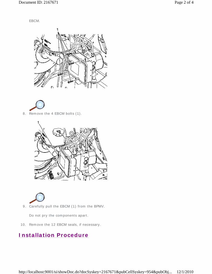
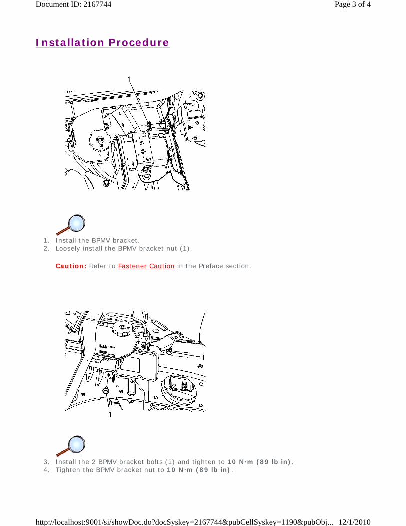
5. Carefully position the BPMV assembly (1) to the BPMV bracket insulators.
6. Install the BPMV bolt (1) and tighten to 10 N·m (89 lb in). 7. Install the radiator surge tank. Refer to Radiator Surge Tank Replacement. 8. Install the underhood electrical center. Refer to Underhood Electrical Center or Junction Block
2009 Saturn VUE - AWD | VUE, VUE Hybrid (VIN Z), Captiva Sport Service Manual | Brakes | Antilock Brake System | Repair Instructions | Document ID: 2158259
Front Wheel Speed Sensor Replacement
Callout Component Name
Warning: Refer to Brake Dust Warning in the Preface section.
Preliminary Procedures
1. Raise and support the vehicle. Refer to Lifting and Jacking the Vehicle. 2. Remove the tire and wheel. Refer to Tire and Wheel Removal and Installation. 3. Remove the brake rotor. Refer to Front Brake Rotor Replacement.
1
Wheel Speed Sensor Electrical Connector
Procedure
Release the electrical connector from the bracket.
2
Wheel Speed Sensor Bolt
Caution: Refer to Fastener Caution in the Preface section.
Tighten 8 N·m (71 lb in)
3
Wheel Speed Sensor
Procedure
Route the wheel speed sensor electrical harness through the splash shield.
2009 Saturn VUE - AWD | VUE, VUE Hybrid (VIN Z), Captiva Sport Service Manual | Brakes | Antilock Brake System | Repair Instructions | Document ID: 1873589
Electronic Traction Control Switch Replacement
The electronic traction control switch (1) located in the driver information display assembly can not be serviced separately. Should the switch assembly need to be replaced, the entire driver information display assembly will need to be replaced. Refer to Driver Information Display Switch Replacement .