36
Training Session of Absorption Chiller
| Date post: | 10-Jul-2016 |
| Category: |
Documents |
| Upload: | faisal-tariq |
| View: | 30 times |
| Download: | 2 times |
Training Session of Absorption Chiller
ABSORPTION CHILLER
MAIN EQUIPMENTSAbsorber EvaporatorCondenser First Stage Steam Generator2nd Stage Steam Generator

Dependence on TemperatureDependence on PressureNature of Chemicals
According to Newton’s Law Of cooling, Evaporation causes cooling effect
Evaporation

Operations Cycle of Absorption Chiller
Properties of Lithium bromide and Water
SpongeWater
Wat
er te
mp.
(°C
)
-18
10
38
66
93
121
0 200
400
600
800
1000
Saturation pressure (mm Hg)
Properties of Lithium bromide
• Molecular Formula : LiBr• APPEARANCE: Clear, colorless solution.• ODOUR: Odorless• BOILING POINT: 140°C.• DENSITY OR SPECIFIC GRAVITY: 1.6 g/ml at 25°C.

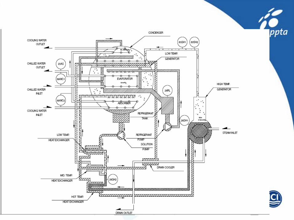
Pre heater
Pre heater
1st Stage generator
2nd Stage generator
Drain cooler
Absorber
Steam
Dilute Solution
Concentrated solution
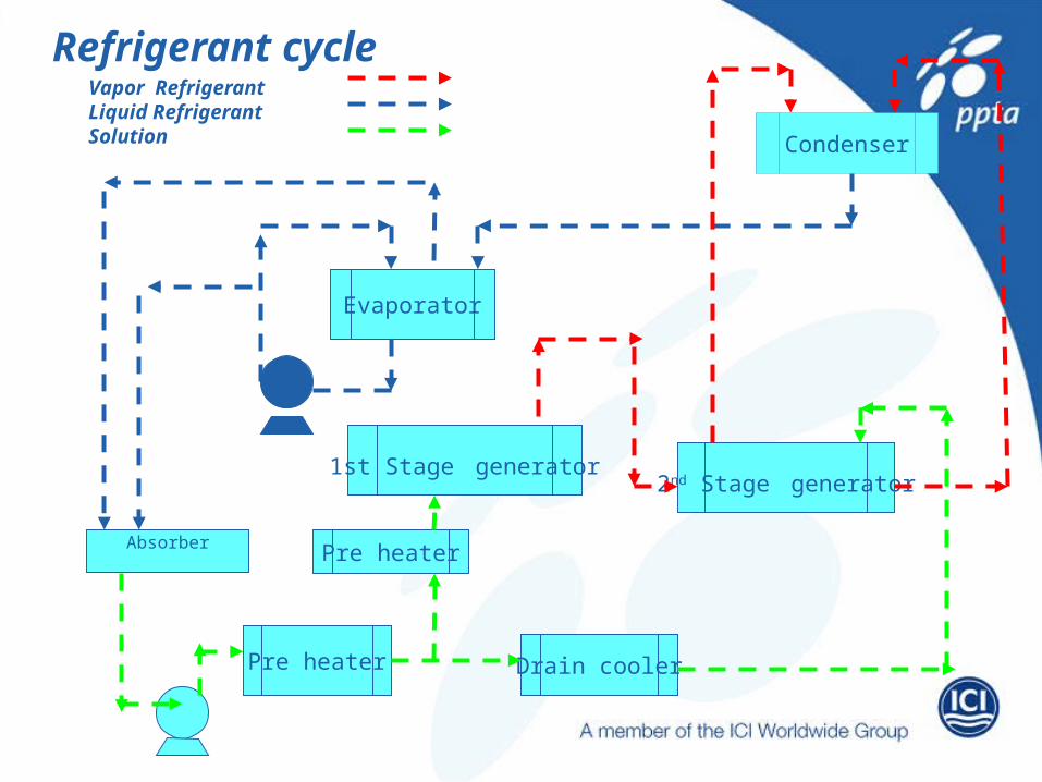
Refrigerant cycle
Absorber
Pre heater
Pre heater
Drain cooler
2nd Stage generator1st Stage generator
Condenser
Evaporator
Vapor RefrigerantLiquid RefrigerantSolution
Back
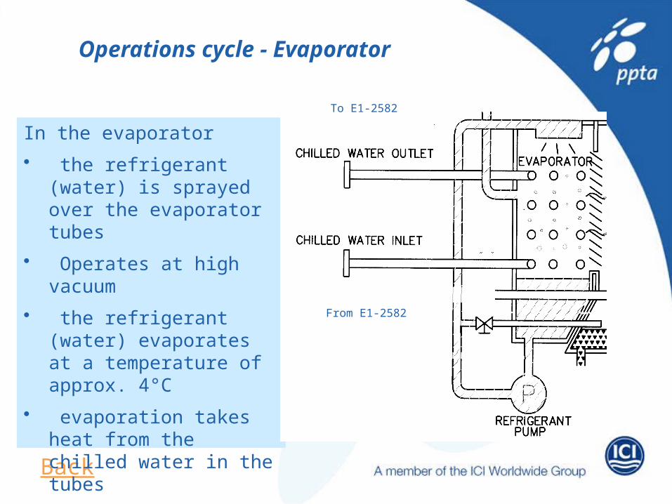
In the evaporator• the refrigerant (water) is
sprayed over the evaporator tubes
• Operates at high vacuum• the refrigerant (water)
evaporates at a temperature of approx. 4°C
• evaporation takes heat from the chilled water in the tubes
Operations cycle - Evaporator
To E1-2582
From E1-2582
Back
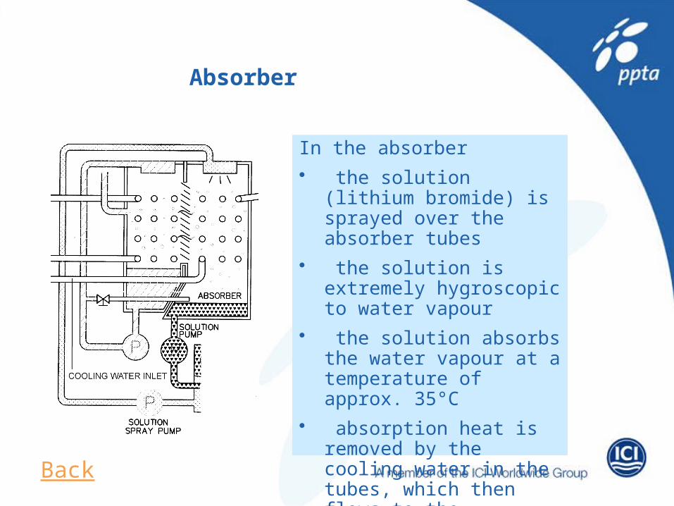
In the absorber• the solution (lithium bromide)
is sprayed over the absorber tubes
• the solution is extremely hygroscopic to water vapour
• the solution absorbs the water vapour at a temperature of approx. 35°C
• absorption heat is removed by the cooling water in the tubes, which then flows to the condenser
Absorber
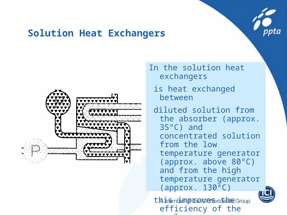
In the solution heat exchangers is heat exchanged between diluted solution from the absorber
(approx. 35°C) and concentrated solution from the low temperature generator (approx. above 80°C) and from the high temperature generator (approx. 130°C)
this improves the efficiency of the cycle
Solution Heat Exchangers
Back
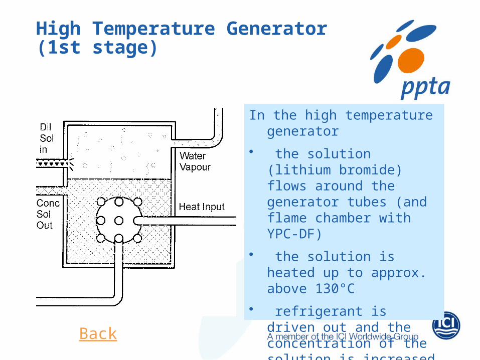
In the high temperature generator• the solution (lithium bromide)
flows around the generator tubes (and flame chamber with YPC-DF)
• the solution is heated up to approx. above 130°C
• refrigerant is driven out and the concentration of the solution is increased
High Temperature Generator (1st stage)
Back
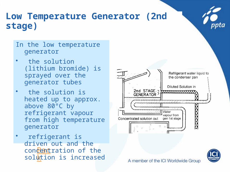
In the low temperature generator• the solution (lithium bromide)
is sprayed over the generator tubes
• the solution is heated up to approx. above 80°C by refrigerant vapour from high temperature generator
• refrigerant is driven out and the concentration of the solution is increased
Low Temperature Generator (2nd stage)
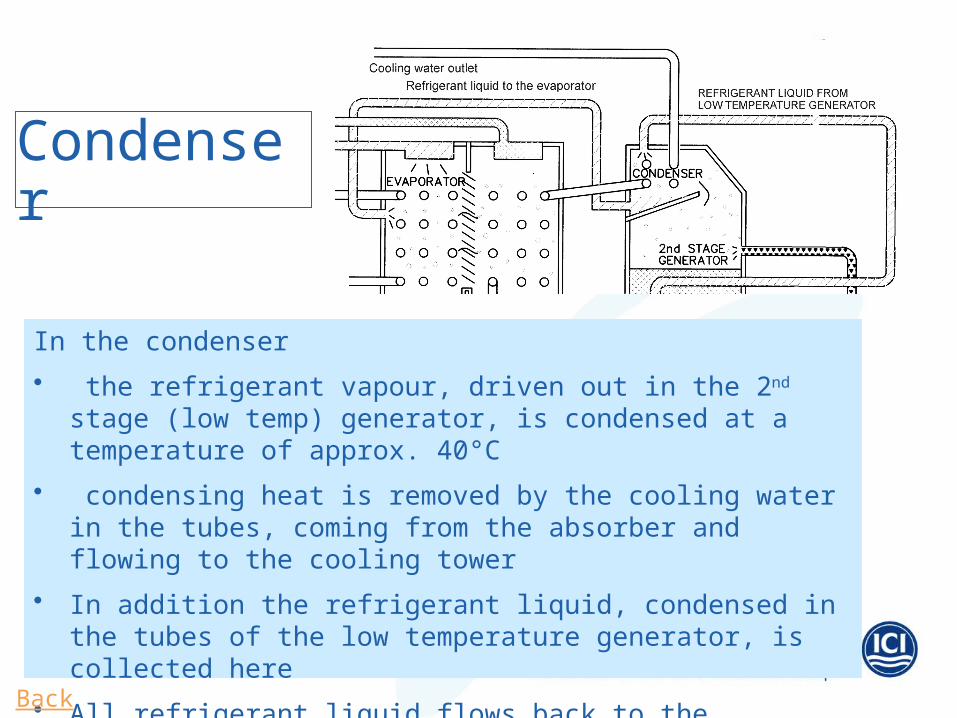
In the condenser• the refrigerant vapour, driven out in the 2nd stage (low temp) generator,
is condensed at a temperature of approx. 40°C• condensing heat is removed by the cooling water in the tubes, coming
from the absorber and flowing to the cooling tower• In addition the refrigerant liquid, condensed in the tubes of the low
temperature generator, is collected here• All refrigerant liquid flows back to the evaporator
Condenser
Back

STARTUP PRECHECKS
• Open cooling water supply & return valves • Open chilled water supply & return valves• Release ESD & confirm power on control panel • Check that no alarm appeared • Check level of absorber, confirm there is no
overflowing• Select local on panel• Check that refrigerant and solution pumps are selected
on auto• Check ready to start indication appearing on panel• Confirm that purge pump has been operated for 5
minutes• Confirm that steam valve on 0% opening• Confirm that condensate drain valve is open and drain
condensate• Remove isolation of steam and press AUTO START
button on panel
START UP
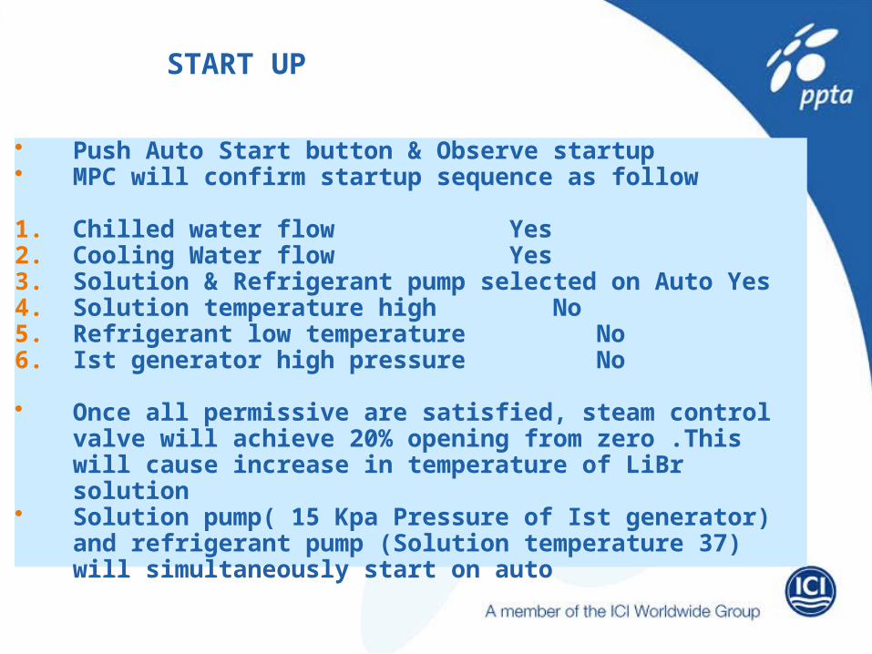
• Push Auto Start button & Observe startup• MPC will confirm startup sequence as follow
1. Chilled water flow Yes2. Cooling Water flow Yes3. Solution & Refrigerant pump selected on Auto Yes4. Solution temperature high No5. Refrigerant low temperature No6. Ist generator high pressure No
• Once all permissive are satisfied, steam control valve will achieve 20% opening from zero .This will cause increase in temperature of LiBr solution
• Solution pump( 15 Kpa Pressure of Ist generator) and refrigerant pump (Solution temperature 37) will simultaneously start on auto
What is Crystallisation and how does it happen?
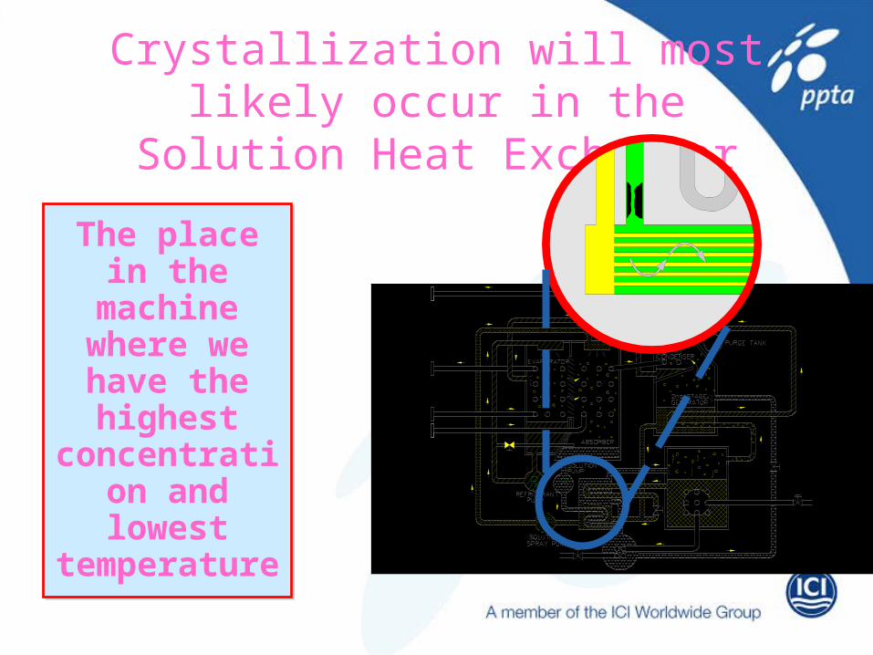
Crystallization will most likely occur in the Solution Heat Exchanger
The place in the machine
where we have the highest
concentration and lowest
temperature

SYMPTOM
• Refrigeration capacity reduced• Solution level is at lower side • Steam flow is normal ,temperature of diluted
solution returned from absorber decreases gradually
• Pump is rotating ,Solution does not flow • Pump overload relay actuated

CAUSES
• High steam pressure increases Concentration of solution in Ist generator
• Insufficient amount of solution flowing • Excessive amount of steam supplied• Cooling water temperature is too high OR suddenly
decreased • In the event of power failure solution flow is stopped and
counter measure not taken in time• Failure of safety relay• Dilution process is insufficient after operation increased
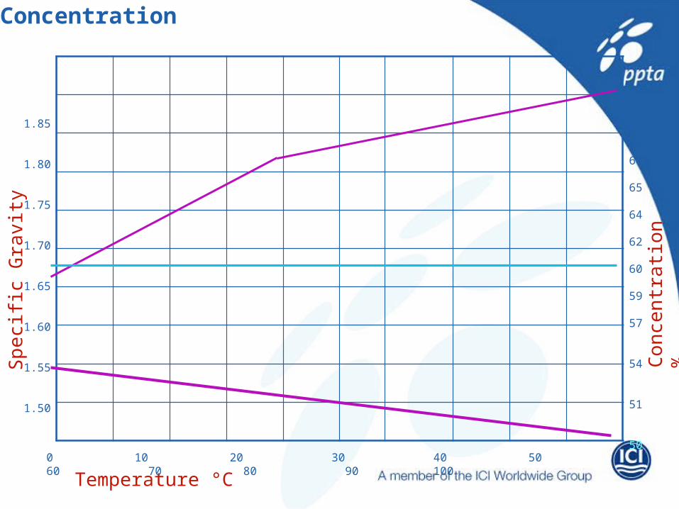
Concentration
Temperature °C
Spec
ific
Grav
ity
Conc
entra
tion
%
1.85
1.80
1.75
1.70
1.65
1.60
1.55
1.50
0 10 20 30 40 50 60 70 80 90 100
67
66
65
64
62
60
59
57
54
51
50
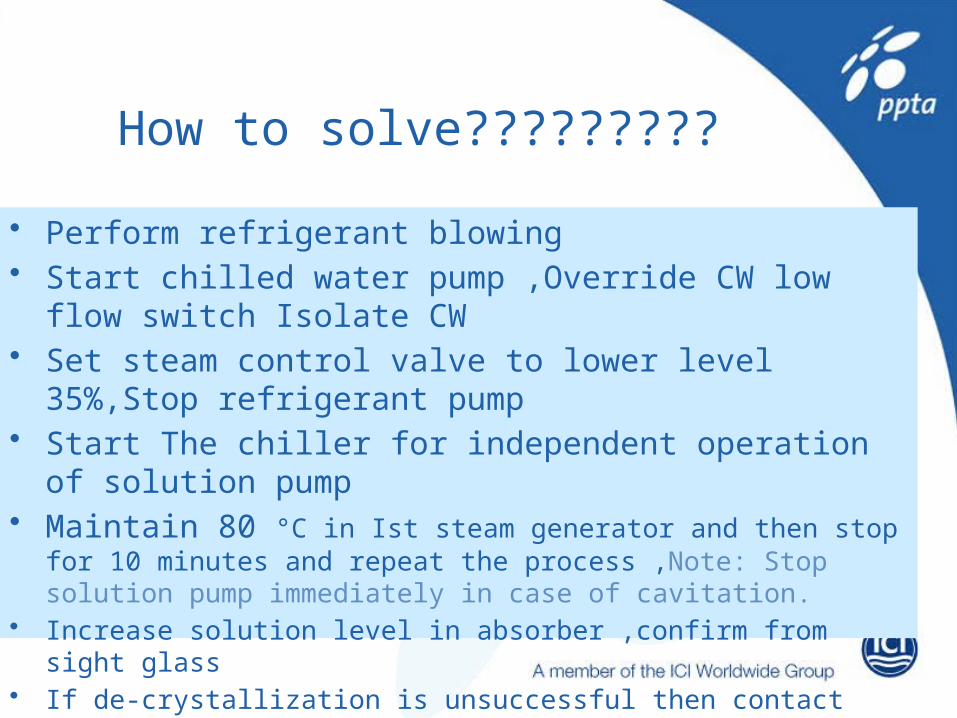
How to solve?????????
• Perform refrigerant blowing• Start chilled water pump ,Override CW low flow switch Isolate
CW• Set steam control valve to lower level 35%,Stop refrigerant pump• Start The chiller for independent operation of solution pump• Maintain 80 °C in Ist steam generator and then stop for 10
minutes and repeat the process ,Note: Stop solution pump immediately in case of cavitation.
• Increase solution level in absorber ,confirm from sight glass• If de-crystallization is unsuccessful then contact with vendor.
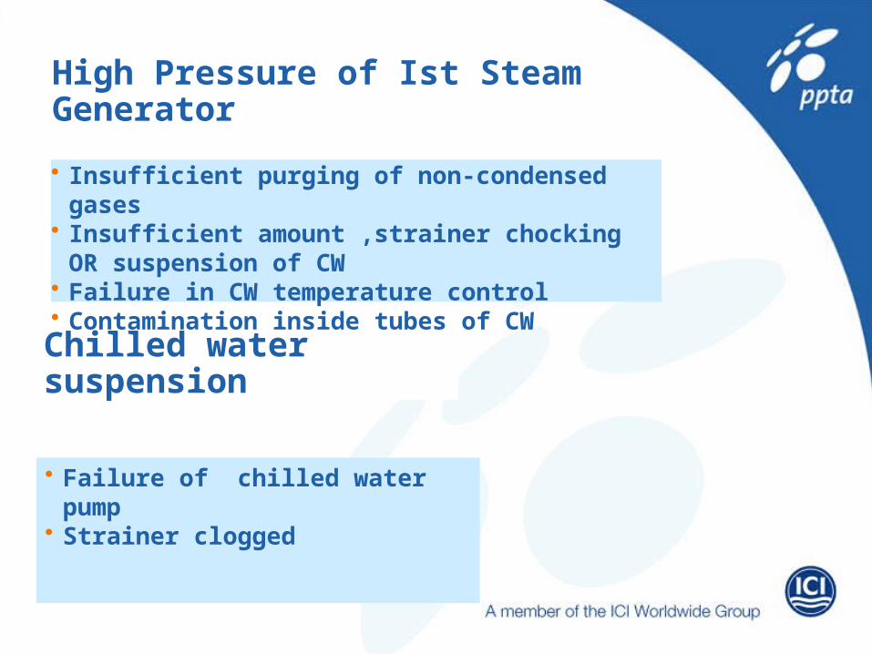
Chilled water suspension
• Insufficient purging of non-condensed gases• Insufficient amount ,strainer chocking OR
suspension of CW• Failure in CW temperature control• Contamination inside tubes of CW
• Failure of chilled water pump• Strainer clogged
High Pressure of Ist Steam Generator
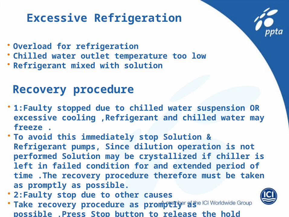
Excessive Refrigeration
• Overload for refrigeration • Chilled water outlet temperature too low• Refrigerant mixed with solution
Recovery procedure
• 1:Faulty stopped due to chilled water suspension OR excessive cooling ,Refrigerant and chilled water may freeze .
• To avoid this immediately stop Solution & Refrigerant pumps, Since dilution operation is not performed Solution may be crystallized if chiller is left in failed condition for and extended period of time .The recovery procedure therefore must be taken as promptly as possible.
• 2:Faulty stop due to other causes• Take recovery procedure as promptly as possible ,Press Stop
button to release the hold state of trouble indication and restart the chiller.
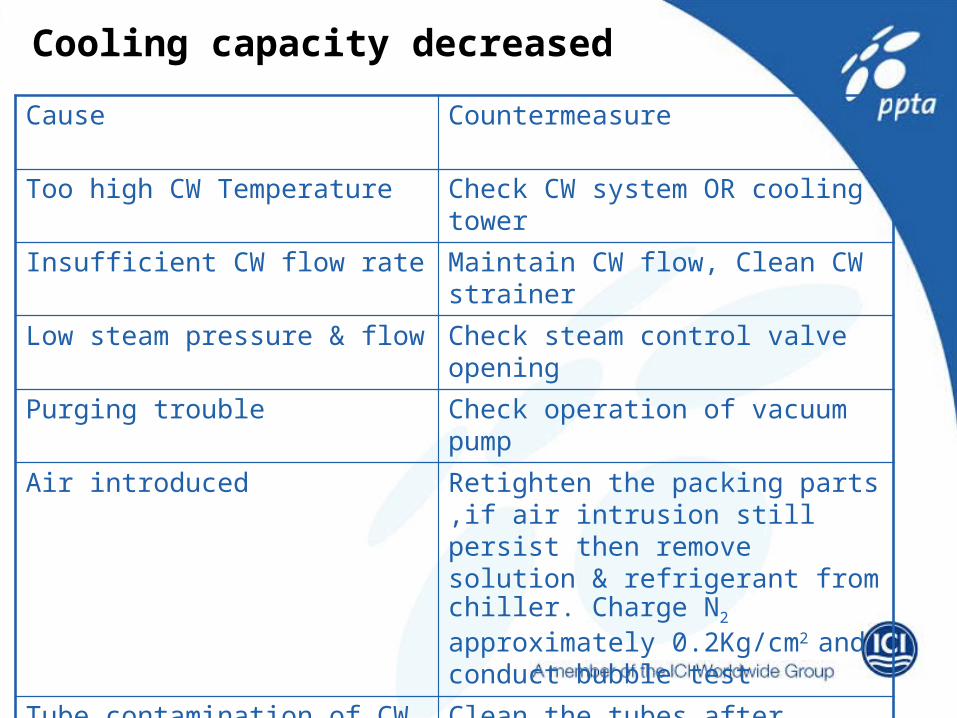
Cooling capacity decreased
Cause Countermeasure
Too high CW Temperature Check CW system OR cooling tower
Insufficient CW flow rate Maintain CW flow, Clean CW strainer
Low steam pressure & flow Check steam control valve opening
Purging trouble Check operation of vacuum pump
Air introduced Retighten the packing parts ,if air intrusion still persist then remove solution & refrigerant from chiller. Charge N2 approximately 0.2Kg/cm2
and conduct bubble testTube contamination of CW side Clean the tubes after draining CW
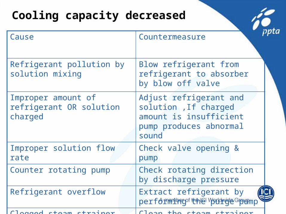
Cooling capacity decreased
Cause Countermeasure
Refrigerant pollution by solution mixing
Blow refrigerant from refrigerant to absorber by blow off valve
Improper amount of refrigerant OR solution charged
Adjust refrigerant and solution ,If charged amount is insufficient pump produces abnormal sound
Improper solution flow rate Check valve opening & pump
Counter rotating pump Check rotating direction by discharge pressure
Refrigerant overflow Extract refrigerant by performing the purge pump
Clogged steam strainer Clean the steam strainer

Refrigerant overflow
Cause Countermeasure
Too high CW temperature Check cooling water system
Refrigerant overcharging If overflow takes place at full load, The refrigerant may be overcharged Extract the proper amount
Too high steam pressure Flow Adjust steam pressure Flow

Poor Performance Of Vacuum Pump
Cause Countermeasure
Oil contaminated Replace the oil
Rust formed on components such as valves
Clean off rust
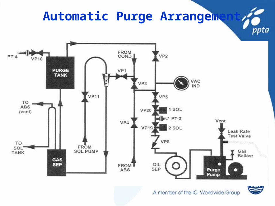
Automatic Purge Arrangement
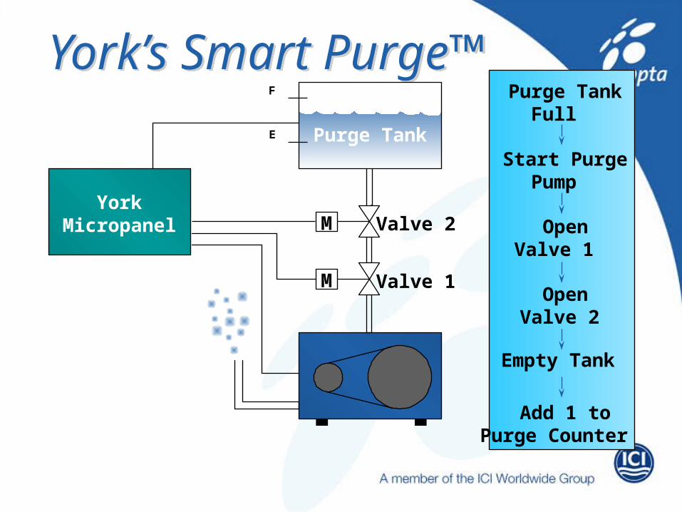
York’s Smart Purge™
YorkMicropanel
Purge Tank
Valve 2
Valve 1
F
E
Purge TankFull
Start PurgePump
OpenValve 1
OpenValve 2
Empty Tank
Add 1 toPurge Counter
M
M
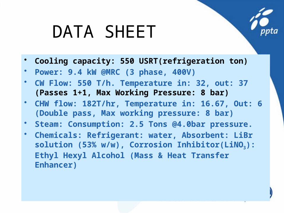
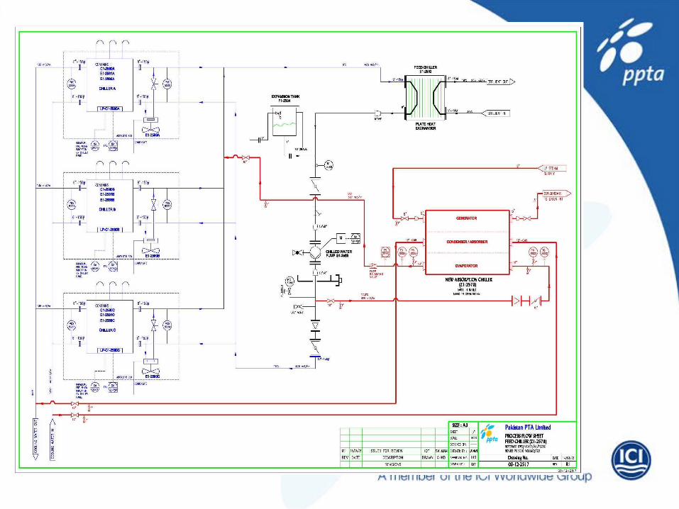
DATA SHEET• Cooling capacity: 550 USRT(refrigeration ton)• Power: 9.4 kW @MRC (3 phase, 400V)• CW Flow: 550 T/h. Temperature in: 32, out: 37 (Passes 1+1, Max
Working Pressure: 8 bar)• CHW flow: 182T/hr, Temperature in: 16.67, Out: 6 (Double pass,
Max working pressure: 8 bar)• Steam: Consumption: 2.5 Tons @4.0bar pressure.• Chemicals: Refrigerant: water, Absorbent: LiBr solution (53% w/w),
Corrosion Inhibitor(LiNO3): Ethyl Hexyl Alcohol (Mass & Heat Transfer Enhancer)

YORK Millennium Panel• Combines the chiller protection functions, optimize the
system efficiency and provides ease of operation.• Following information is provided as standard.1. CHW entering/leaving temperature.2. CW entering/leaving temperature.3. Generator Temperature and pressure.4. Refrigerant and solution temperature.5. Operating hours and number of starts.6. Number of purge cycles (last 7 days)7. Steam control valve position in %age8. Operating indication for refrigerant/solution and purge pumps9. Steam pressure and temperature to generator
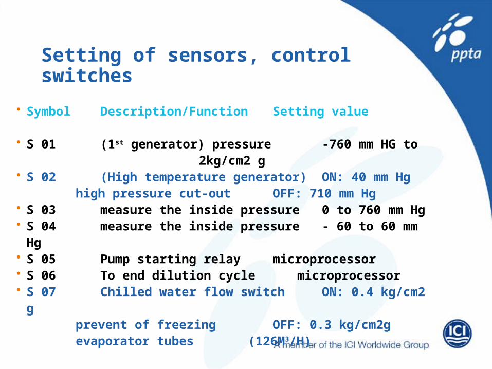
Setting of sensors, control switches
• Symbol Description/Function Setting value
• S 01 (1st generator) pressure -760 mm HG to 2kg/cm2 g
• S 02 (High temperature generator) ON: 40 mm Hghigh pressure cut-out OFF: 710 mm Hg
• S 03 measure the inside pressure 0 to 760 mm Hg• S 04 measure the inside pressure - 60 to 60 mm Hg• S 05 Pump starting relay microprocessor• S 06 To end dilution cycle microprocessor• S 07 Chilled water flow switch ON: 0.4 kg/cm2 g
prevent of freezing OFF: 0.3 kg/cm2g evaporator tubes (126M3/H)
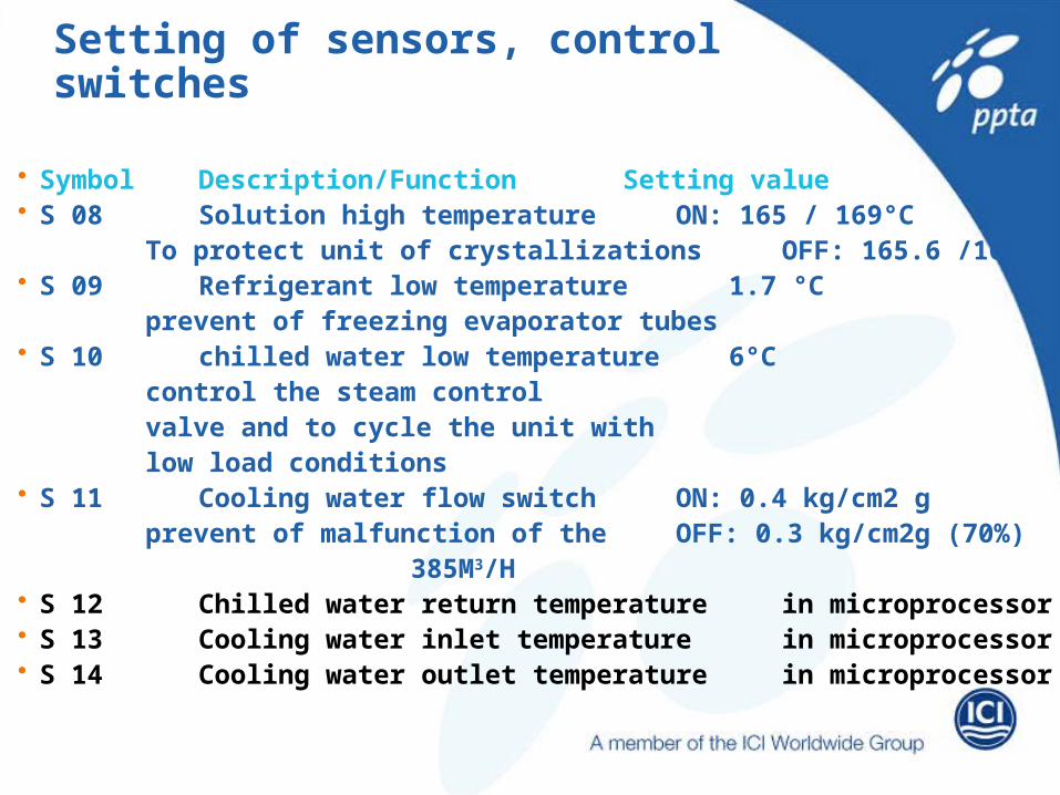
Setting of sensors, control switches
• Symbol Description/Function Setting value• S 08 Solution high temperature ON: 165 / 169°C
To protect unit of crystallizations OFF: 165.6 /169°C• S 09 Refrigerant low temperature 1.7 °C
prevent of freezing evaporator tubes• S 10 chilled water low temperature 6°C
control the steam controlvalve and to cycle the unit withlow load conditions
• S 11 Cooling water flow switch ON: 0.4 kg/cm2 gprevent of malfunction of the OFF: 0.3 kg/cm2g
(70%)385M3/H
• S 12 Chilled water return temperature in microprocessor• S 13 Cooling water inlet temperature in microprocessor• S 14 Cooling water outlet temperature in microprocessor