Subsidence Phenomena of the Coastal Structures into Offshore Sandy Seabed: A Review
A.B.M. Khan-Mozahedy
Abstract— Coastal structures especially dikes and breakwaters may have balance on offshore sandy seabed. Foremost causes of lowering crest are consolidation of the foundation layers, wave-induced scouring and liquefaction. Many studies have been conducted to figure out the sinking phenomena of the coastal structures over the past decades. This article has reviewed the findings of observational, physical and real case studies to present comprehensive overview of the gradual sinking phenomena of maritime structures into sandy seabed. This study also reveals which sinking phenomena might have higher influence at what circumstances of marine hydrodynamics. Both consolidation and scour are quantifiable and may be incorporated during design of the crest level, while places susceptible to liquefaction are not suitable as construction site without ground improvement.
Index Terms— sinking, sandy seabed, consolidation, scour, seepage, current, liquefaction
—————————— ——————————
1 INTRODUCTIONoast is a dynamic equilibrium area, continuously balanc-ing natural changes and increasing human uses. Numer-ous structures such as breakwaters, groins, seawalls,
dikes, composite seawall system etc. are constructed in the coastline for the following reasons:
• To protect properties from damage; • To safeguard land from erosion by wave action and
flooding and; • To exploit reneawable wave energy (Khan-
Mozahedy, 2014).
When a breakwater is placed on a sandy sea platform, it changes flow dynamics in the immediate neighbourhood (Sumer and Fredsøe, 2002). Breakwaters are normally con-structed on the seabed that has had previous consolidation experiences of cyclic wave loadings. However, self weight increases pore pressure in expense of the pore volume in the soil during construction. When pore pressure dissipates, soil grains consolidate. Wave-induced scour removes sand from around individual blocks and armour units of rubble mound breakwaters, and thus the blocks gradually penetrate into the seabed due to self weight under gravity (Sumer et al. 1999). When wave breaks at the toe of the structure, wave could stirs up sand from around the block and the backflow removes the suspended sand from the site. Sumer et al. (2001b) has studied the suction of sediments from around armour units of break-water on a loose bed and this study has found that vortices stir up and suck sands from between the armour blocks. Bartels et al. (2000) has given an example where top row of Accropodes subsides apparently due to extensive scour at the toe of the breakwater. Seepage pressure at the slope of the rubble mound breakwater reduces effective stresses in the sand
grains, and the grain moves out causing sinking of the indi-vidual blocks. This phenomenon is known as sand boiling and typically occurs in the vicinity of a sheet pile (Suzuki et al. 1998). On the other side, liquefaction is the state of the soil where soil-water mixture acts like fluid and the soil loses its bearing capacity. When wave passes over the loosely packed seabed, pore pressure builds up in expanse of the pore vol-ume. As wave action continues, pore pressure continues to accumulate and reaches at a level exceeding the overburden pressure. In that situation, effective stresses in the sand grains vanish and soil behaves like fluid. This phenomenon is called residual liquefaction and blocks sink in such a liquefied soil because of its own gravity (Suzuki et al., 1998; Sumer et al., 1999; Kirca, 2013). Sumer et al. (1999) has mentioned few evi-dences of sinking offshore breakwaters or floatation of in-struments and submarine pipelines during storms. When wave trough passes over the seabed, negative pore pressure (in excess of the hydrostatic pressure) develops across the soil depth causing a sudden lifting pressure. If this lifting pressure exceeds the submerged weight of the soil, the soil becomes liquefied. This phenomenon is called momentary liquefaction and occurs in a seabed having air content (Sakai et al., 1994; Sumer and Fredsøe, 2002). Therefore, the three major causes of sinking of breakwaters are: a) Consolidation of the sandy seabed, when a breakwater is placed, b) Scour in the seabed, when a breakwater obstructs waves and currents and c) Lique-faction, when waves exert pressure in the seabed that reaches the critical mean normal effective stress of the soil. Numerous studies have been conducted to understand the scour and liquefaction phenomena that occur on the foundation of the coastal structures over the past decades, but none of them combines all the causes of sinking coastal structures in a single study. The aim of the present article is to review research find-ings till nowadays, comparing and analyzing them and point-ing out possible future research lines to improve our knowledge in order to decrease sinking phenomena in coastal structures placed on offshore sandy seabed.
C
————————————————
• A. B. M. Khan-Mozahedy is currently working as Sub-Divisioinal Engineer, Bangladesh Water Development Board (BWDB), Dhaka-1000, Bangladesh and Erasmus Mundus PhD student at the Department of Applied Physics, University of Cadiz, Puerto real campus, Spain, PH- 008801914723628. E-mail: [email protected]
2. RECENT RESEARCHES ON SCOURING AND LIQUEFACTION In the recent past decades, many researches contribute to un-derstand the physics of the interaction between wave and seabed at the shore face of a maritime structure. Early re-searches have concentrated on the morphological changes such as long shore and cross shore profiles, consolidation and scour phenomena on the shallow sea platform due to the pres-ence of the coastal structures.
2.1 Researches on scouring around breakwaters Scouring seabed near the coastal structures because of flow vortices, turbulence and currents is a major threat to stability and sustainability. Major advancement has already been made during past few decades in understanding coastal flow dy-namics and related erosion phenomena, and their mitigation measures. During 1990s among others, Hsu and Silvester (1989) has performed two model tests to understand scouring along breakwaters and Hughes and Fowler (1991) has studied wave induced scour system dynamics in front of vertical breakwaters in two dimensional case. Oumeraci (1994) re-views previous research finding of the scouring and related breakwater failures and concludes that the key mechanism of scouring is the standing waves that create a steady streaming which presumably results in scour and deposition in front of the breakwater. Baquerizo and Losada (1998) has also studied toe erosion and sediment dynamics around a mound breakwa-ter. Among many researchers during 1990s, Fredsøe and Su-mer (1997), Sumer and Fredsøe (1997, 2000, 2002) and Sumer at al. (2005) have made many physical modelling tests to ob-tain important contribution on understanding scouring mech-anisms at both trunk section and round head of the rubble mound breakwaters. Sumer et al. (2001b) gives suction mech-anism and sediment transport system from between armour units of the breakwaters. Many numerical models have been developed and conducted to study scouring and deposition around breakwaters and other coastal structures (vertical sea-wall, pipelines, etc.) in response to obstructional changes in flow dynamics (example: Young et al., 2009; Jeng and Ye, 2013). Very recently, Muñoz-Perez et al. (2015) and Khan-Mozahedy et al. (2015a) have presented a real case of sinking submerged structures in Cadiz bay, Spain where scouring seabed was the prime cause of sinking the concrete modules. Finally, and as a sign of the present relevance of this topic, Nielsen et al. (2015) has studied sinking of armour layer around a vertical cylinder exposed to waves and currents.
2.2 Researches on liquefaction Many catastrophic failure events of coastal structures draw attention of the recent researchers (Sakai et al., 1994; Suzuki et al., 1998; Sumer et al., 1999; Jeng and Ye, 2012; Kirca, 2013, etc.) to understand the physics of liquefaction under wave actions in sandy seabed. Research on building up of pore pressure and liquefaction failure has been started back to three to four decades. During this time, evolution of research methods starts from simple observation of the liquefaction phenomena (example: Bruun, 1979; Kramer, 1988) to physical modelling in the laboratory flume (example: Sakai et al. 1994; Suzuki et al. 1998; Sumer et al. 1999; Kirca, 2013 etc.) and finally to various
numerical modelling (e.g. Jeng and Ye, 2012). Sakai et al. (1994), Suzuki et al. (1998) and Sumer et al. (1999) are nearly pioneer researches in physical modelling experiments in la-boratory flumes for liquefaction problems in sandy seabed and many researchers have followed them during the last 20 years. Sakai et al. (1994) has used a U-shaped tank with both ends closed to see effects of water level fluctuations and flow oscillations simultaneously on block subsidence into sand bed. Suzuki et al. (1998) has used a wave flume where a sand bed box is fixed underneath of the flume. A feed water system is developed at bottom of the sand bed to produce initially loose sand bed conditions and to generate seepage flow liquefaction. Regular waves are mainly applied to the sand bed at different water depth with the help of a wave absorber in order to min-imize wave reflections and then a caisson has been also in-stalled to investigate standing waves. Sumer et al. (1999) has also used a wave flume (along with a piston type wave gener-ator) with constant water depth but without feed water sys-tem. Sand bed (in a box) is left for sometimes before testing to ensure normal consolidation and measures are taken to make the sand bed free from any bubbles. Blocks (both spheres and cubes) are also put on the sand bed to observe sinking process. Following Sumer et al. (1999), many researchers have exploit-ed similar wave flume tests (some of them have shaking facili-ties too) setting to study liquefaction, including Sumer et al. (2010) which has studied sinking cover stones in coastal struc-tures and Kirca (2013) which has studied sinking of irregular shaped blocks into liquefied soil. Medina et al (2006a, 2006b) have presented a real case sinking of submerged coastal struc-ture into offshore sandy seabed in Cadiz, Spain where lique-faction is suspected as a prime cause for this rapid sinking.
3. CONSOLIDATION Consolidation is a process of decreasing soil volume (strain) in response to the applied stress. When stress is applied to a soil mass, particles become packed together more tightly and therefore this process reduces volume by shrinking. In case of saturated soils, water is squeezed out from the pore volume of the soil during application of stress. The time required to re-move the water out from clayey soil mass could be years but it could be a matter of seconds for sandy layers because of high permeability (Jang et al., 2007 etc.). Consolidation of saturated sandy layers beneath a breakwater occurs during construction and imposition of the structural loads. This consolidation causes settlement which in turn could be a cause of defor-mation of the structure. Consolidation may be caused by the following processes (Holtz et al. 2010): 1. Deformation of soil particles: sharp and coarse particles
become broken and rounded because of high stress; 2. Relocation of soil particles: soil grains move to the lower
stress level; 3. Expulsion of water or air from void spaces: water, air and
gas are squeezed out from the pore volume during shrinkage.
Consolidation of non-cohesive sand layers is immediate upon load increment and settlement calculation is simple compared
to normally consolidated or over consolidated clay or silty clay layers (Chung et al., 2006; Holtz et al. 2010 etc.). In design of coastal structures, bearing capacity is the utmost criteria of any foundation stability. Structural load imposes stresses on the soil layers and these stresses initiate strain across the soil depth. In response to the stress and shear deformation, soil grains reshuffle and consolidate in expense of the pore vol-ume. In this consolidation process, initially pore pressure in-creases and gradually dissipates depending on the permeabil-ity of the soil and drainage conditions. Therefore top surface beneath the structure shrinks and the coastal structures settle (Fig. 3.1).
Figure 3.1: Consolidation of sandy layers
In coarse soils (sands), volume change resulting from structur-al loading occurs immediately because increasing pore water pressures are dissipated rapidly due to the high permeability. Therefore, during construction, the settling process is rapid initially and gradually decreases and ultimately stops when the settling process is stabilized. The extent of the settlement depends on the net dead loads (specific weight) of the struc-ture, live loads (from wave action) and properties of the foun-dation soil such as void ratio, angularity of the soil grains, grain size distribution, permeability etc. Loose sand settles more compared to dense sand. Well graded sands are not equally compressible like uniform sand. Similarly rounded sand is less compressible than angular sand. Consolidation process takes more time in clayey beds due to poor drainage conditions. Settlement calculation of structures on clay layers is quite different and slightly complicated (Mitchell and Soga, 2005). Shear stress induced by waves and currents also facili-tates pore pressure accumulation and dissipation in the con-solidation processes during construction of the structures. Therefore at the end of the construction, the subsoil becomes stiffer and denser with increased bearing capacity. Armour units are placed at toe of the coastal structures to protect them wave actions (Yagci et al. 2004). Contact area between armour units and seabed surface become less in random dumping and placement. So, dumping of armour units could concentrate bearing pressure on relatively small area and thus increases settlement with the driving pressure. Coastal Engineering Manual (USACE, 2003) has shown that
consolidation of the subsoil in the coastal structures eventually lowers the crest level. Differential settlement reduces func-tional integrity of the armour layers. Therefore, prediction of the sinking depth is crucial for structural integrity and func-tionality. Void ratio “e” is the sole criterion for sandy seabed in determining the extent of consolidation upon static and dy-namic loading. This parameter “e” can be defined as the ratio of the volume of void (Vv) to the volume of solid (Vs) in a sand mass (volume of soil grains, Vt).
𝑒 = 𝑉𝑣𝑉𝑠
= 𝑉𝑣𝑉𝑡−𝑉𝑣
(3.1)
The volume of soil (Vt) and volume of void (Vv) from the sample soil mass can be determined during the laboratory tests. If a soil mass has initial void ratio e0, maximum possible void ratio (emax) and minimum possible void ratio (emin), then Relative density “Dr” of the in-situ soil can be calculated from the following equation (e.g. Sumer et al. 1999).
𝐷𝑟 = 𝑒𝑚𝑎𝑥−𝑒0𝑒𝑚𝑎𝑥−𝑒𝑚𝑖𝑛
(3.2)
In the Eq. 3.2, theoretically maximum possible relative density of the soil is 100%. However, both Coastal Engineering Man-ual (USACE, 2003) and Sumer et al. (1999) consider that 65-85% relative density of the soil implies dense soil. If pore pres-sure develops and dissipates without liquefaction during con-struction of a breakwater, then maximum possible settlement depth must depend on relative density or void ratio of the soil. If a granular soil has initial void ratio “e0” and a estimated change in void ratio “Δe” due to breakwater construction, then design settlement “S” of the soil depth “d” can be calculated by the following equation (Holtz et al., 2010; Mitchell and Soga, 2005).
𝑆 = 𝑝 × 𝛥𝑒1+𝑒0
(3.3)
So, from Eq. 3.3, it can be noted that Δe is a design parameter for settlement calculation which corresponds to the relative density values of dense sand (0.65-0.85). Average value of the changes in void ratio (Δe) across the soil depth should be tak-en into consideration if the thickness of the sandy layer is large. If the thickness of the sand layer above the rigid bed becomes infinitely large, then the design thickness of the load bearing stratum can be determined from the load transfer mechanism. Foundation of a breakwater may be considered as spread type on confined sand layer, where stress level de-creases along the depth of the soil. Alternatively, consolidation can be determined by 1D Oedometer test (Holtz et al., 2010) in the laboratory, especially when clay contents are significantly high in the soil mass.
4. SCOUR Besides consolidation of the underlying sand layers, scour is an important sinking mechanism of armour units of coastal structures such as breakwater. Offshore breakwater (both
emerged and submerged type) causes changes of flow pattern around it and creates the following one or more flow dynam-ics situation (Open University, 1999; Sumer at al. 2001a; Sumer and Fredsøe, 2002).
• Diversion or contraction of flow, when flow passes
through the blocks and armour units across the struc-tures
• Horseshoe vortex or lee-wake vortices, when wave breaks in front of the structure
• Steady streaming along water column in front of the structures, when incoming wave and reflected wave create standing wave
• Turbulence generation during interaction of flow and current with armour units of the coastal structures
• Reflection, diffraction, shoaling of waves, wave plunging and wave breaking in front of the structure
• Changes of water depth and therefore changes of flow interaction and dynamics because of cyclic tidal variation
• Pressure difference and seepage flow in the ground water beneath the structure, when wave trough pass-es over the seabed
• Seepage flow because of water level difference during tidal variation
Flow dynamics is crucial for stability of the structures and their sandy foundations. Scour is a threat to the stability of the coastal structures on sandy sea floor. Foundation stability largely depends on the optimal prediction of consolidation, liquefaction potentiality of the sandy bottom and extension of the scour depth and their protective measures. Severe scours because of flow dynamics are normally observed either at the toe of the trunk section or at the round head of the breakwa-ters (Bruun and Kjetstrup, 1981; Fredsøe and Sumer, 1997; Sumer and Fredsøe, 1997 and 2002; Sumer et al. 2005). Chang-es of flow dynamics and their contribution to the scour in the sandy seabed around breakwaters are discussed in the follow-ing sections.
4.1 Properties of scour initiation Scour and deposition and their alternating positions around coastal structures depend on the properties of the seabed, type and pattern of the structure and the intensity of the shear stress. Initiation of the scour on the seabed can be determined on the three criteria: amplification factor, Shield parameter and Keulegan-Carpenter number (Sumer et al. 2001a; Sumer and Fredsøe, 2002). These three criteria are defined in the fol-lowing sections.
4.1.1 Amplification factor The flow changes exert additional shear stress on the seabed adjacent to the breakwater, which increases local sediment transport capacity. Thus turbulence leads to scour or erosion around blocks of the breakwater. Degree of the turbulence and flow current in the vicinity of the structure regulate sand transport either in suspension or no suspension mode or both. The increase of the bed shear stress is expressed as the ampli-fication factor “α”, which can be defined as follow (Sumer and
Fredsøe, 2002):
𝛼 = 𝜏𝜏∞
(4.1)
Where τ is the increased bed shear stress around a block of the breakwater due to changes of the flow pattern and τ∞ is the normal bed stress of the undisturbed flow. The value of α in marine environment (i.e. random sea state wave and tidal variation) depends on the complex dynamics of the flow and geometry of the structure. If α > 1.0, then the sand around blocks presumably erodes while α < 1.0 means the sand de-posits around blocks. Severe scour during storm normally be backfilled by sand deposition within a considerable time scale, and in this process of scour and deposition, armour units/blocks sink in the sandy seabed.
4.1.2 Shield parameter Shield parameter is most important criterion for sediment movement and transport researches in the marine environ-ment. Consequently, it is an important criterion in determin-ing scour extent and pattern in sandy seabed around blocks of breakwater. Undisturbed Shield parameter “θ” can be defined as follow (Sumer and Fredsøe, 2000 and Sumer et al., 2001a):
𝜃 =𝑈𝑓2
𝑔(𝑠−1)𝑑 (4.2)
Where, Uf = undisturbed bed shear velocity = �(τ∞/ρ) τ∞ = undisturbed maximum bed shear ρ = density of water g = acceleration due to gravity s = specific gravity of the sand grains d = sand grain size
Critical value of the Shield parameter “θcr” corresponds to the initiation of the sand particles in the seabed and it is a function of the Reynolds number. Reynolds number (R) can be defined as follow:
𝑅 = 𝑑𝑈𝑓
𝜈 (4.3)
In Eq. (4.3), ν is the kinematic viscosity. An empirical relation-ship exists between Reynolds number and critical value of the Shield parameter “θcr” for marine sandy seabed (Sumer and Fredsøe, 2002). If θ <θcr then sediment transport does not take place far from the structure and if θ >θcr then sediment transport prevails over the entire bed.
4.1.3 Keulegan-Carpenter number Keulegan-Carpenter number is a parameter in determining scour initiation at the roundhead of the breakwater because of horseshoe vortex and turbulence created by incident waves and tidal currents. The Keulegan-Carpenter number (KC) can be defined as follow (Sumer and Fredsøe, 2002):
𝐾𝐾 = 𝑈𝑚𝑇𝑚
𝐵 (4.4)
Where, Um is the maximum orbital velocity of water particles
If orbital velocity is assumed to be sinusoidal, then 𝐾𝐾 = 2𝜋𝑎𝐵
, where “a” is the amplitude of the orbital motion of the water particles at the bed and “B” is the average diameter of the block; the average diameter or width of the entire roundhead of the breakwater, if the whole section as a single unit.
4.1.4 Mode of sediment transport When wave actions and currents originate (i.e. α > 1.0 and θ >θcr) a sediment particle movement, it may be transported either on sliding over the seabed (no suspension mode of sed-iment transport) or into suspension (suspension mode of sed-iments transport). Generally, very fine sands, silts and clay come into suspension and move into the place where flow equilibrium stage (i.e. α ≤ 1.0 and θ ≤ θcr) prevails (deposition). Sand particles that come into suspension will remain and be transported in suspension only when the following condition is fulfilled (Sumer and Fredsøe, 2002):
𝜔𝑈𝑓
< 1.0 (4.5)
Where, ω is the fall velocity of the sand particle and Uf is the bed shear velocity. Coarse sands, cobbles etc. move on sliding (i.e. ω/Uf> 1.0) until it reaches the flow equilibrium (i.e. α ≤ 1.0 and θ ≤ θcr). Direction of particle movements depends on the flow conditions and so positions of scouring and deposi-tion may be shifted based on the instantaneous flow situa-tions.
4.2 Global effects of local scour
4.2.1 Local scour around armour units
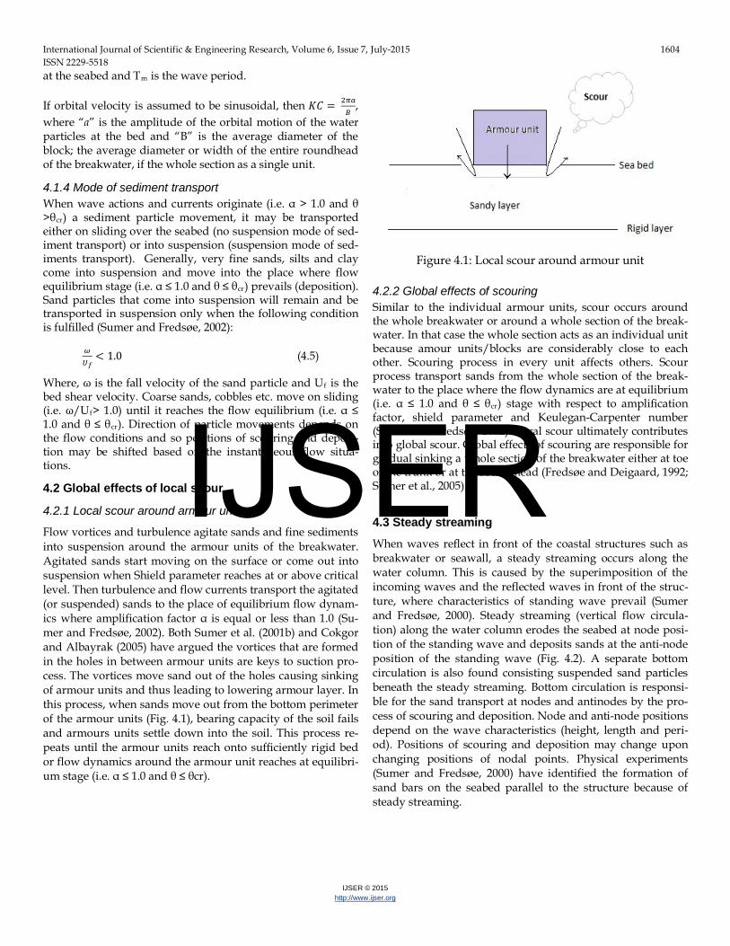
Flow vortices and turbulence agitate sands and fine sediments into suspension around the armour units of the breakwater. Agitated sands start moving on the surface or come out into suspension when Shield parameter reaches at or above critical level. Then turbulence and flow currents transport the agitated (or suspended) sands to the place of equilibrium flow dynam-ics where amplification factor α is equal or less than 1.0 (Su-mer and Fredsøe, 2002). Both Sumer et al. (2001b) and Cokgor and Albayrak (2005) have argued the vortices that are formed in the holes in between armour units are keys to suction pro-cess. The vortices move sand out of the holes causing sinking of armour units and thus leading to lowering armour layer. In this process, when sands move out from the bottom perimeter of the armour units (Fig. 4.1), bearing capacity of the soil fails and armours units settle down into the soil. This process re-peats until the armour units reach onto sufficiently rigid bed or flow dynamics around the armour unit reaches at equilibri-um stage (i.e. α ≤ 1.0 and θ ≤ θcr).
Figure 4.1: Local scour around armour unit
4.2.2 Global effects of scouring Similar to the individual armour units, scour occurs around the whole breakwater or around a whole section of the break-water. In that case the whole section acts as an individual unit because amour units/blocks are considerably close to each other. Scouring process in every unit affects others. Scour process transport sands from the whole section of the break-water to the place where the flow dynamics are at equilibrium (i.e. α ≤ 1.0 and θ ≤ θcr) stage with respect to amplification factor, shield parameter and Keulegan-Carpenter number (Sumer and Fredsøe, 2002). Local scour ultimately contributes into global scour. Global effects of scouring are responsible for gradual sinking a whole section of the breakwater either at toe of the trunk or at the round head (Fredsøe and Deigaard, 1992; Sumer et al., 2005).
4.3 Steady streaming
When waves reflect in front of the coastal structures such as breakwater or seawall, a steady streaming occurs along the water column. This is caused by the superimposition of the incoming waves and the reflected waves in front of the struc-ture, where characteristics of standing wave prevail (Sumer and Fredsøe, 2000). Steady streaming (vertical flow circula-tion) along the water column erodes the seabed at node posi-tion of the standing wave and deposits sands at the anti-node position of the standing wave (Fig. 4.2). A separate bottom circulation is also found consisting suspended sand particles beneath the steady streaming. Bottom circulation is responsi-ble for the sand transport at nodes and antinodes by the pro-cess of scouring and deposition. Node and anti-node positions depend on the wave characteristics (height, length and peri-od). Positions of scouring and deposition may change upon changing positions of nodal points. Physical experiments (Sumer and Fredsøe, 2000) have identified the formation of sand bars on the seabed parallel to the structure because of steady streaming.
Figure 4.2: (A) Steady streaming and (B) Scour-deposition
profile (Modified from Sumer and Fredsøe, 2000)
Alternating scouring and deposition cause gradual sinking of armour units into the sandy seabed in front of the structures. Steady streaming process for oblique wave attack still requires further study and analysis (Sumer and Fredsøe, 2002).
4.4 Scour depth Scour depth is an important design parameter in determining the extent of sinking of breakwater in response to various scour process, especially steady streaming. Scour depth de-pends on various factors such as amplification factor, Shield parameter, scouring process, size and shape of armour unit at the breakwater, breakwater type and dimension etc. Armour units/blocks will not sink more than scour depth. Scour depth (S) by means of steady streaming correlates by water depth (h) and wave parameters (wave height, H, and wave length, L). Steady streaming may not induce any shear stress at a deeper water depth. Therefore, S/H tends to 0, when h/L tends to ∞.
4.4.1 Scour depth assessment at trunk section
Sumer and Fredsøe (1997; 2000) has proposed modified empir-ical methods for determining maximum scour depth at the trunk section in the rubble mound breakwater. The co-relation of scour depth with wave parameters and water depth was shown graphically by these authors (Fig. 4.3).
Figure 4.3: Scour depth (S) prediction (A) Vertical wall and (B) Rubble mound breakwater (Modified from Sumer and Fredsøe, 2000; 2002)
Xie (1981) gives (Fig. 4.4A) an empirical expression for maxi-mum scour calculation at vertical wall breakwater, given by:
𝑆𝐻
= 𝐴
[sinh�2𝜋ℎ𝐿 �]1.35 (4.6)
Where, the value of ‘A’ in eq. 4.6 is 0.4 for fine sand and 0.3 for coarse sand (no suspension mode of sand transport and scour).
Based on experimental results (Fig. 4.3B), Sumer and Fredsøe (2000) adapted the empirical eq. 4.6 to estimate maximum scour depth for ‘no suspension mode of sand transport’ at the toe of the trunk section of rubble mound breakwater. Estimat-ed scour depth was also compared with the numerical results of other researchers and good agreement was found. The em-pirical equation is as follows:
𝑆𝐻
= 𝑓(𝛼)
[sinh�2𝜋ℎ𝐿 �]1.35 (4.7)
in which f(α) is given by:
𝑓(𝛼) = 0.3 − 1.77 exp(− 𝛼
15) (4.8)
In eqs. (4.6), (4.7) and (4.8), S is the maximum scour depth and α is the slope of the armour of the rubble mound breakwater.
4.4.2 Scour depth assessment at the round head Scour process at the round head of a breakwater is different from that at the trunk section and therefore, prediction process is also different. Keulegan- Carpenter (KC) number has im-portant role in this scour process (Eq. 4.4). Sumer and Fredsøe (1997) proposed an empirical expression for the maximum scour depth (S) at the round head of a vertical wall breakwater (Eq. 4.9), given by:
𝑆𝐵
= 0.5𝐾[1 − exp{−0.175(KC− 1)}] (4.9)
where, B is the width of the breakwater at the head section
and C is an uncertainty factor with mean value of 1.0 and a standard deviation of 0.6.For rubble mound breakwaters, Sumer and Fredsøe (1997) modified the eq. 4.9 as follows:
𝑆𝐵
= 0.04𝐾1[1− exp{−4(KC − 0.05)}] (4.10)
Where, C1 is an uncertainty factor with a mean value 1.0 and a standard deviation 0.2. For plunging wave breaker induced scour, maximum scour depth does not depend on KC but depends on wave parameters (water depth h, significant wave height, Hs, and peak period Tp) and Sumer and Fredsøe (1997) have given the following expression:
𝑆𝐻𝑠
= 0.01 𝐾2(𝑇𝑝�𝑔𝐻𝑠ℎ
)1.5 (4.11)
Where, C2 is the uncertainty factor with a mean value of 1.0 and a standard deviation of 0.34.
4.5 Storm effects on scouring and sinking Storm waves may produce larger scour and therefore larger sinking on the armour units of the breakwater during storms. However, the scour may be backfilled by a deposition process after storm. The time required to backfill the entire scour by means of deposition is called time scale of the scour process (Sumer and Fredsøe, 2002). If scour is backfilled by deposition process, further sinking of the armour units may only occur when the subsequent storm exceeds the scour depth that was already reached in the previous storm.
4.6 Seepage Seepage in the sandy seabed (porous medium) is an important phenomenon in the gradual sinking of coastal structures. Seepage forces come into seabed by way of wave loading and unloading and by means of tidal variation (Atigh and Byrne, 2000; Cheng and Liu, 1986). Seepage contributes to the scour process in marine structures and their gradual sinking only.
4.6.1 Seepage across trunk section of a breakwater
In impervious breakwater, the sandy seabed beneath the struc-tures feels seepage pressure pulse (which is sinusoidal in character) during wave loading and unloading (Dias and Monkmyer, 1990). During tidal cycles, the forward or back-ward seepage pressure force persists for a longer time depend-ing on the cycle times. This seepage pressure exerts lateral forces on the sand particles and creates tendency to moves out it from beneath of the structures. Thus this seepage pressure creates sand boiling at edges of the truck sections of the struc-tures. The emitted sands during sand boiling are washed away by waves and currents. As sands move out from beneath of the structures, the structures gradually sink into the sandy seabed (Fig. 4.4).
Figure 4.4: Seepage pulse and sand boiling
In permeable coastal structures, water flows through the struc-tures during wave periods and tidal cycles. This flow removes smaller particles from the structures and causes scours on the seabed around armour units. Although, Cheng and Liu (1986) and few other researchers have studied on seepage flow be-neath a buried pipeline and its effects on floatation of the pipe-line under wave actions, there are very limited research on wave and or tide-induced seepage pressure and flow beneath breakwaters and its contribution on scouring and lowering of the structures.
4.6.2 Groundwater Seepage along shoreline
Groundwater flows through the shore face during low tide because of hydraulic head differences. This seepage exerts pressure on the sand particles to move out from the shore face. The portion of the breakwater, which crosses the shoreline, experiences groundwater flow related seepage pressure dur-ing low tide. Seepage moves out sand particles from beneath of the structure along the edges. This phenomenon is known as sand boiling (Fig. 4.5). The discharged sands and sediments wash away in wave actions and currents during high tide. So, coastal structure such as breakwater and groin gradually set-tles down at the shoreline. Coastal dike becomes wider and settles down into the ground surface for the same reason. Ex-tent of seepage pressure and rate of drawdown depends on the permeability of the sandy layers and hydraulic head dif-ference. Coastal Engineering Manual (USCE, 2001; 2003) in-cludes groundwater seepage and piping in the shoreline as one of the failure modes of the armour layers of the coastal protective structures.
4.7 Current Breaking wave creates cross shore current (including rip cur-rents) while oblique wave creates long shore current (Open University, 1999). Tidal fluctuations are mostly responsible for tidal current and flushing close to coast and tidal rivers at a global scale (Khan-Mozahedy and Rahman, 2015). When cur-rent passes through armour units of breakwater (Fig. 4.6), flow velocity increases manifold because of flow contraction. This amplified current makes erosion of sand around armour units (depending on shear stress amplification factor “α” and Shield parameter “θ” of the seabed) and subsequently transport them to the place of flow equilibrium place of α ≤ 1.0 and θ ≤ θcr. Moreover, wave action intensifies as water depth reduces in front of the structure during low tide. As water depth decreas-es during low tide, pattern of wave exposure changes (eventu-ally incidence of wave breaking increases) and therefore, scouring and sand transport become intensified, and location of scouring and deposition changes. These phenomena con-tribute in gradual sinking of armour units and in lowering the crest level of the breakwater. The seabed at head of the break-water is eroded more by high speed flow (depending on the KC number) in tidal recession during low tide. Sumer and Fredsøe (1997) have discussed this type of scour at round head of the breakwater. This type of scour is responsible for dis-placement and sinking of armour units at the head section of the structures.
Figure 4.6: Scouring and sinking process under wave current and tidal current
5. LIQUEFACTION Liquefaction is an important phenomenon of the sandy seabed where effective stress between sand grains become zero be-cause of continuous building up of pore pressure under wave actions and therefore the sand water mixture as a whole acts like fluid without having any bearing capacity. Therefore, once a seabed is liquefied under wave action, any object rest-ing on the liquefied seabed sinks immediately deep into the sand water mixture. Liquefaction generates in two mecha-nisms: building up of pore pressure and upward pressure gradient (Sumer et al., 2006).
5.1 Pore pressure build up When progressive waves pass over a sandy seabed, a shear deformation induces in the seabed. This deformation rear-ranges the sand grains and thus sand bed is compressed under each wave crest and similarly expanded under each wave trough. As a result, pore pressure builds up in the sandy layer in expanse of pore volume in each compression (Fig. 5.1). Both Suzuki et al. (1998) and Sumer el al. (1999) have found that loosely pack sand layer with low permeability has high lique-faction potential for sea state wave conditions. If a sandy sea-bed layer of having pore pressure, p experiences a wave of period T, then accumulated period-averaged pore pressure, P, will be as follows:
𝑃 = 1𝑇∫ 𝑝𝑝𝑝𝑇0 (5.1)
For progressive waves, building up of pore pressure continues and eventually reaches at maximum value (Pmax) where it equals to or slightly exceeds the overburden pressure (σo'). In this circumstance, effective stresses between sand grains van-ish; sand layer is liquefied and loses its bearing capacity. This phenomenon is called residual liquefaction, and generally occurs in unconsolidated backfill or loosely packed seabed. At the end of the liquefaction and subsequent consolidation pro-cess, sandy seabed becomes more compacted layer with high relative density.
Figure 5.1: Pore pressure builds up and accumulation
5.1.1 Partial liquefaction and consolidation of sand layers
Wave exposure of sandy seabed causes pore pressure accumu-lation (eq. 5.1) of which ultimate quantity depends on the wave height and time of exposure. Sumer et al. (1999) con-cludes that sandy seabed liquefies at critical wave height (Hcr) and wave height (H) that is smaller than the critical wave height (Hcr) cannot generate enough cyclic shear stress in the soil to cause liquefaction by pore pressure accumulation. If accumulated pore pressure does not reach the value of the overburden pressure, then sand layer does not liquefy and accumulated pore pressure decreases with the increasing time as water is drained out and sand layer becomes compacted by means of consolidation. Therefore, Partial liquefaction can be defined as the state of the sandy seabed where pore pressure
builds up under wave action and/or seepage pressure, but it may not sufficient to liquefy the soil. Partial liquefaction might exert upward drag which causes frictional sliding and reshuf-fling of the sand grains and induces settling armour units of the breakwater in expanse of pore volume. Partial liquefaction and subsequent settling of the sandy seabed can be considered as consolidation process (Section 3).
5.1.2 Sinking of objects in liquefied soil Once seabed is liquefied, any object like an armour unit of a breakwater, with a specific gravity higher than the critical one, sinks into the sand water mixture due to its own gravity. Su-mer et al. (1999) has studied sinking of a sphere and a cube in a physical modelling test and has found ultimate sinking depth as a function of the gravity. This physical model study indicates that sinking of an object starts immediately after liquefaction of the seabed and sinking velocity remains steady until it reaches close to the impermeable layer and then grad-ually decreases and ultimately stops at impermeable layer or at a layer with sufficient rigidity. Both sphere and cube tests indicate that actual shape of armour units has no dramatic influence on sinking depth in a liquefied soil. Kirca (2013) has also studied more elaborately the sinking of irregular shape blocks into marine seabed under wave-induced liquefaction and has found similar results. Therefore sinking depth of an armour unit in a wave-induced liquefied sandy seabed may be as large as the entire thickness of the layer.
5.1.3 Effects of history of wave exposure and re-liquefaction Sumer et al. (1999) has done experiments where the soil bed is exposed to the same waves (H= 16.6 cm and T=1.6 sec) more than once. The experimental results show that the accumulat-ed pore pressure (P) is reduced tremendously (only 0.6 cm water column at depth 16.5 cm where as it is 11.5 cm water column at the same point during first wave exposure) when the soil bed is exposed to the waves for second time and P is practically absent when the soil is exposed to the same waves for the third time. Pore pressure accumulates in expanse of pore volume in sandy seabed. Pore volume reduces largely during first wave of exposure by means of grains rearranging and reshuffling, and therefore, there might not have enough room in the pore volume for reshuffling and rearranging in the second and subsequent wave exposures. So, pore pressure accumulates slightly only in the second wave of exposure. This is a very important observation in determining liquefac-tion potential of a sandy seabed under wave exposure. Experi-ences of wave exposures reduce liquefaction potential to a large extent. Suzuki et al. (1998) has proposed a term ‘re-liquefaction’ for the already compacted sandy bed. Liquefaction does not occur for smaller waves and residual pore pressure diminishes. However, liquefaction reappears latter at larger waves. Re-liquefaction probably occurs due to compaction by smaller waves being limited to the upper surface of the seabed. Larger waves (for example waves during stormy sea states) are capa-ble to liquefy the bed again when compaction is expanded deep into the sandy seabed.
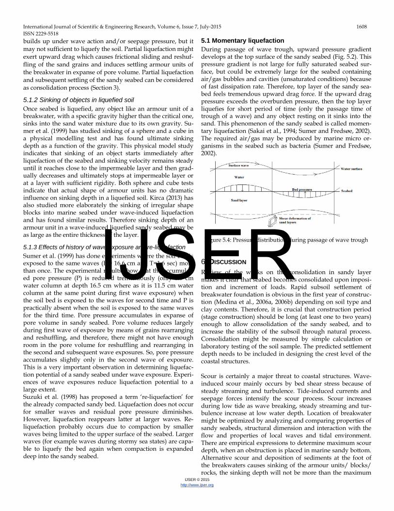
5.1 Momentary liquefaction During passage of wave trough, upward pressure gradient develops at the top surface of the sandy seabed (Fig. 5.2). This pressure gradient is not large for fully saturated seabed sur-face, but could be extremely large for the seabed containing air/gas bubbles and cavities (unsaturated conditions) because of fast dissipation rate. Therefore, top layer of the sandy sea-bed feels tremendous upward drag force. If the upward drag pressure exceeds the overburden pressure, then the top layer liquefies for short period of time (only the passage time of trough of a wave) and any object resting on it sinks into the sand. This phenomenon of the sandy seabed is called momen-tary liquefaction (Sakai et al., 1994; Sumer and Fredsøe, 2002). The required air/gas may be produced by marine micro or-ganisms in the seabed such as bacteria (Sumer and Fredsøe, 2002).
Figure 5.4: Pressure distribution during passage of wave trough
6. DISCUSSION Review of the works on the consolidation in sandy layer makes it clear that seabed becomes consolidated upon imposi-tion and increment of loads. Rapid subsoil settlement of breakwater foundation is obvious in the first year of construc-tion (Medina et al., 2006a, 2006b) depending on soil type and clay contents. Therefore, it is crucial that construction period (stage construction) should be long (at least one to two years) enough to allow consolidation of the sandy seabed, and to increase the stability of the subsoil through natural process. Consolidation might be measured by simple calculation or laboratory testing of the soil sample. The predicted settlement depth needs to be included in designing the crest level of the coastal structures.
Scour is certainly a major threat to coastal structures. Wave-induced scour mainly occurs by bed shear stress because of steady streaming and turbulence. Tide-induced currents and seepage forces intensify the scour process. Scour increases during low tide as wave breaking, steady streaming and tur-bulence increase at low water depth. Location of breakwater might be optimized by analyzing and comparing properties of sandy seabeds, structural dimension and interaction with the flow and properties of local waves and tidal environment. There are empirical expressions to determine maximum scour depth, when an obstruction is placed in marine sandy bottom. Alternative scour and deposition of sediments at the foot of the breakwaters causes sinking of the armour units/ blocks/ rocks, the sinking depth will not be more than the maximum
scour depth. Scouring seabed in the onshore side of a sub-merged structure by means of overtopping flow has been detected and it is subjected to further study (Khan-Mozahedy et al., 2015b). Armour units of a breakwater could sink and reach at the bottom of the sandy seabed within a short period in the lique-fied soil. Therefore, liquefaction failure of coastal structure is catastrophic. So, geographical location of a breakwater should be selected in such a way that has little or no liquefaction po-tential. Loosely packed seabed along with undrained condi-tion (for example loosely packed silt layer) is prerequisite of building up pore pressure. Number of wave cycles to cause liquefaction in sandy seabed increases tremendously with decreasing shear stress and with increasing relative density (Sumer and Fredsøe, 2002). Sumer et al. (1999) clearly indi-cates that compacted sand bed (relative density Dr about 60%-70%) has almost no liquefaction potential. Liquefaction sus-ceptibility decreases with increasing permeability and there-fore, coarse sandbed has low liquefaction potentiality. Re-searchers use very fine sands or silts to cause liquefaction in laboratory conditions. For example, Sakai et al. (1994) used soil of median grain size (d50) 0.25 mm but Suzuki et al. (1998) used soil with d50 0.08 mm, Sumer et al. (1999) used soil with d50 0.045 mm, Sumer et al. (2006) used soil with d50 0.06 mm, Kirca (2013) used soil with d50 0.07 mm. Sandy seabed which has experiences of the wave exposures is less susceptible to liquefaction. Re-liquefaction may only occur when wave height becomes higher from any previous wave exposures in the history. Coastal structures such as breakwater should be made by avoiding liquefaction in choosing appropriate loca-tion in term of relative density of the seabed and recorded history of wave exposures. Any loosely packed seabed (in-cluding backfills, and nourished seashore) having rich organ-isms (which causes momentary liquefaction) should be avoid-ed in placing armour units. Combined effects of consolidation and scour might be higher, but may not be cumulative and both are measurable and pre-dictable in the sandy seabeds. So, final crest level of breakwa-ter can be designed based on testing and prediction of consol-idation and scour. But these calculations are based in laborato-ry tests and therefore may not be accurate in certain cases. That’s the reason why analysis of real or prototype cases should be performed especially when predictions of sinking become necessary for coastal submerged structures in sandy bottom under different wave and tidal scenarios. Thus, ap-propriate protective measures may be designed to reduce scouring. Sometimes, physical modeling study becomes inevi-table when determination of real causes of sinking coastal structures is difficult by means of monitoring especially in real sea state conditions. On the other hand, liquefaction is cata-strophic to the breakwaters. No breakwater can stand against liquefaction but it is not a common problem and only it can be a problem for loose sandy seabeds like backfill. Compacted or dense sand beds are not susceptible to liquefaction. Liquefac-tion potential of sandy seabed has to be measured before choosing a site for breakwater construction. Any object might sink instantly in liquefied soil; combined effects of consolida-
tion, scour and liquefaction are much higher. Simply, it can be concluded from review analysis that any sandy seabed that has liquefaction potential cannot be considered for breakwater construction unless it is improved sufficiently through com-paction. Storm waves, tsunami waves and earthquake may be catastrophic for breakwaters and may induce failures by means of scouring and or liquefaction.
7. CONCLUSIONS After studying and analyzing recent research findings about consolidation, scour and liquefaction of breakwater founda-tion in sandy seabed, the following conclusions can be drawn in brief:
• Breakwaters gradually sink in the sandy seabed de-pending on soil properties, and wave and tidal char-acteristics.
• Consolidation of sandy seabed depends on degree of the compactness and it is predictable. Sufficient time should be made available for proper consolidation during construction.
• Wave-induced scour can be predicted and maximum scour depth should be incorporated in the crest level design of the breakwaters along with settlement due to consolidation.
• Liquefiable seabed such as backfill might not be ac-ceptable as construction site.
REFERENCES [1] Animoto, K., Takahashi, S., 1994. Design and construction of caisson
breakwaters- the Japanese experience. Coastal Engineering 22, 57-77 [2] Atigh, E., Byrne, P.M., 2000. The effects of drainage conditions on
liquefaction response of slopes and the inference for lifeline. Proc. Of the 14th Vancouver Geotechnical Symposium, Canada
[3] Bartels, A., Kloos, M., Phelp, D., 2000. Failure and repair of the toe of an Accropode breakwater. 26th International Coastal Engineering Conference, ASCE, Australia, Vol. 1, Paper-74
[4] Bruun, P., 1979. Common reasons for damage or breakdown of mound breakwaters. Coastal Engineering 2, 261-273
[5] Bruun, P., Kjelstrup, S., 1981.Practical views on the design and con-struction of mound breakwaters. Coastal Engineering 5, 171-192
[6] Baquerizo, A., Losada, M.A., 1998.Sediment transport around a mound breakwater: The toe erosion problem. Proc. 26th International Conference on Coastal Engineering, Copenhagen, vol-2, 1721-1729
[7] Cheng, A.H-D., Liu, P. L-F. 1986. Seepage force on a pipeline buried in a poroelastic seabed under wave loadings. Applied Ocean Re-search 8(1), 22-32
[8] Cokgor, S., Albayrak, I., 2005. Suction removal of sediment from between armor blocks at non-uniform bed. RMZ-Materials and Ge-oenvironment, vol.-52 (1), 9-11.
[9] Cihan, K., and Yuksel, Y., 2011. Deformation of rubble-mound breakwaters under cyclic loads. Coastal Engineering58,528-539
[10] Catano-Lopera, Y.A., Landry, B.J., Garcia, M.H., 2011. Scour and burial mechanics of conical frustums on a sandy bed under combined flow conditions. Ocean Engineering38,1256-1268
[11] Chung, S.G., Kim, S.K., Kang, Y.J., Im, J.C., Prasad, K.N., 2006. Fail-ure of a breakwater founded on a thick normally consolidated clay layer. Geo-technique 56 (3), 393–409
[12] USACE, 2001. Coastal Engineering Manual: Scour and scour protec-tion. Chapter VI-5-6, Engineer Manual EM 1110-2-1100, U.S. Army Corps of Engineers
[13] USACE, 2003. Coastal Engineering Manual: Part-V Chapter 3: Shore protection projects. Engineer Manual EM 1110-2-1100, U.S. Army Corps of Engineers
[14] Dias, F., Monkmeyer, P.L., 1990. The effects of wave-induced seepage on an impervious breakwater with an extended foundation base. Coastal Engineering 14, 417-437
[15] Fredsøe, J., Sumer, B.M., 1997. Scour at the round head of a rubble mound breakwater. Coastal Engineering29, 231-262
[16] Fredsøe, J., Deigaard, R., 1992. Mechanics of coastal sediment transport. World Scientific, Singapore
[17] Holtz, R. D., Kovacs, W. D., Sheahan, T. C., 2010. An introduction to geotechnical engineering. 2nd edition, Prentice hall
[18] Hsu, J.R.C., Silvester, R., 1989. Model test results of scour along breakwaters. Waterway, Port, Coastal, and Ocean Engineering 115,175-192
[19] Hughes, S.A., Fowler, J.E., 1991. Wave-induced scour kinematics at vertical walls. Proc. Coastal Sediments’91, ASCE, Vol.-2, 1886-1900
[20] Jeng, D.S., Ye, J.H., 2012. Three-dimensional consolidation of a po-rous unsaturated seabed under rubble mound breakwater. Ocean Engineering 53, 48-59
[21] Jang, I.S., Kwon, O.S., Park, W.S., Jeong, W.M., 2007. Lateral and consolidation behaviors of seabed-type breakwater for very soft ground. Ocean Engineering 34, 2240-2250
[22] Kramer, S.L., 1988. Triggering of liquefaction flow slides in coastal soil deposits. Engineering Geology 26, 17-31
[23] Kirca, V.S.O., 2013. Sinking of irregular shape blocks into marine seabed under wave-induced liquefaction. Coastal Engineering 75, 40-51
[24] Kuriyama, Y., Banno, M., Kishi, H., Satoh, T., Mizuuchi, K., 2013.Morphological change of nourished beach behind submerged breakwater on the Niigata coast. Coastal Dynamics
[25] Khan-Mozahedy, A.B.M., 2014. Hydraulic performance of a 3-D composite seawall system for renewable wave energy conversion. Int. Journal of Scientific and Engineering Research 5(11), 249-257
[26] Khan-Mozahedy, A.B.M., Rahman, M.R., 2015. Socio-technical eval-uation of selected water control structures in the South-West region of Bangladesh. Proc. of the 5th International Conference on Water and Flood Management, Dhaka. pp. 399-410
[27] Khan-Mozahedy, A.B.M., Muñoz-Perez, J.J., Neves, M.G., 2015a. Monitoring of the water particle velocity field near the seabed under different wave and tidal scenarios: a real case. Proc. of 5th Int. Conf. on Water and Flood Management, pp. 275-286
[28] Khan-Mozahedy, A.B.M., Muñoz-Perez, J.J., Neves, M.G., Sancho, F., Cavique, R., (2015b). Mechanics of scouring and sinking of sub-merged structures in mobile bed: a physical modelling study. (under review for publication)
[29] Liu, H., Jeng, D., 2007. A semi-analytical solution for random wave-induced soil response and seabed liquefaction in marine sediments. Ocean Engineering 34, 1211-1224
[30] Medina, J. R., Muñoz, J.J., Tejedor, B., Gomez-Pina, G., Fages, L., 2006a. Actuacion experimental con diques modulares en Santa maria del mar (Cadiz), Redes neuronales, socavacion y licufeccion de are-nas. II Congreso Nacional de la AsociacionTecnica de Puertos y Coas-tas, 301-322.
[31] Medina, J. R., Muñoz-Perez, J. J., Gomez-Pina, G., 2006b. Transmis-sion and reflection of modular detached breakwaters. Proc. of the 30th international conference of Coastal Engineering, vol.5, 4350-4361
[32] Mitchell, J.K., Soga, K., 2005. Fundamentals of soil behaviour. Third edition, John Wiley and Sons, Inc.
[33] Munoz-Perez, J.J., Khan-Mozahedy, A.B.M., Neves, M.G., Tejedor, B., del Campoand, J.M., Negro, V., 2015. Sinking of concrete modules in-to a sandy seabed: a case study.Coastal Engineering 99, pp. 26-37
[34] Myrhaug, D., Rue, H., 2003. Scour below pipelines and around verti-cal piles in random waves. Coastal Engineering 48, 227-242
[35] Nielsen, A.W., Probst, T., Petersen, T.U., Sumer, B.M., 2015. Sinking of armour layer around a vertical cylinder exposed to waves and cur-rent. Coastal Engineering 100, 58-66
[36] Niedoroda, A.W., Dalton, C., 1982. A review of the fluid mechanics of ocean scour. Ocean Engineering 9(2), 159-170
[37] Oka, F., Yashima, A., Miura, K., Ohmaki, S., Kamata, A., 1995. Set-tlement of breakwater on submarine soil due to wave-induced lique-faction. Proc. of the fifth international offshore and polar engineering conference
[38] Open University, 1999. Waves, Tides and Shallow-Water Processes. Milton Keynes, UK.
[39] Oumeraci, H., 1994. Scour in front of vertical breakwaters - Review of problems. In: Proc. International Workshop on Wave Barriers in Deep Water, Port and Harbour Research Institute, Yokosuka, 281-307
[40] Sakai, T., Asce, M., Gotoh, H. Yamamoto, T., 1994. Block subsidence under pressure and flow. Coastal Engineering 1541-1552.
[41] Spierenbureg, S.E.J., 1987. Seabed response to water waves. PhD thesis, Technical University of Delft, The Netherlands.
[42] Sumer, B.M., Fredsøe, J., 1997. Scour at the head of a vertical-wall breakwater. Coastal Engineering 29,201-230
[43] Sumer, B.M., Fredsøe, S., Christensen, S., Lind, M.T., 1999.Sinking/floatation of pipelines and other objects in liquefied soil under waves. Coastal Engineering 38, 53-90
[44] Sumer, B.M., Fredsøe, J., 2000. Experimental study of 2D scour and its protection at a rubble-mound breakwater. Coastal Engineering 40, 59-87
[45] Sumer, B.M., Whitehouse, R.J.S., Torum, A., 2001a. Review: Scour around coastal structures: A summary of recent research. Coastal Engineering 44,153-190
[46] Sumer, B.M., Cokgor, S., Fredsøe, J. 2001b.Suction of sediment from between armour blocks. Hydraulic Engineering 127(4), 293–306
[47] Sumer, B.M., Fredsøe, J., 2002. The Mechanics of Scour in the Marine Environment. Advanced series on Ocean Engineering, Vol.17, World Scientific Press, Singapore
[48] Sumer, B.M., Fredsøe, J., Lamberti, A., Zanuttigh, B., Dixen, M., Gislason, K., Penta, A.F.D., 2005. Local scour at roundhead and along the trunk of low crested structures. Coastal Engineering 52, 995-1025
[49] Sumer, M., Hatipoglu, F.H., Fredsøe, J., Sumer, S. K., 2006. The se-quence of sediment behaviour during wave-induced liquefaction. Sedimentology 53, 611-629
[50] Sumer, B.M., Dixen, F.H., Fredsøe, J., 2010. Cover stones on liquefia-ble soil bed under waves. Coastal Engineering 57, 864-873
[51] Suzuki, K., Takahashi, S., Kang, Y., 1998. Experimental analysis of wave-induced liquefaction in a fine sandbed. Coastal Engineering 3643-3654.
[52] Xie, S.L., 1981. Scouring patterns in front of vertical breakwaters and their influence on the stability of the foundations of the breakwaters. Delft University of Technology, The Netherlands.
[53] Yagci, O., Kapdasli, S., Cigizoglu, H.K., 2004. The stability of the antifer units used on the breakwaters in case of irregular placement. Ocean Engineering 31, 1111-1127


![Stability of Low Crested and Submerged Breakwaters with ...€¦ · breakwaters has been extensively studied [15], and the stability on low crested and submerged breakwaters was addressed](https://static.documents.pub/doc/80x56/5fc2e4ed58734d00807b1cc4/stability-of-low-crested-and-submerged-breakwaters-with-breakwaters-has-been.jpg)


