DISTRIBUTION STATEMENT A: Approved for public release; distribution is unlimited. DESTRUCTION NOTICE - For classified documents, follow the procedures in DoD 5200.22-M, National Industrial Security Program Manual, Chapter 5, Section 7. For unclassified, limited documents, destroy by any method that will prevent disclosure of contents or reconstruction of the document. ANNULAR AIR LEAKS IN A LIQUID HYDROGEN STORAGE TANK A.G. Krenn*, R. C. Youngquist, and S. O. Starr NASA Kennedy Space Center KSC, FL ABSTRACT Large liquid hydrogen (LH2) storage tanks are vital infrastructure for NASA, the DOD, and industrial users. Over time, air may leak into the evacuated, perlite filled annular region of these tanks. Once inside, the extremely low temperatures will cause most of the air to freeze. If a significant mass of air is allowed to accumulate, severe damage can result from nominal draining operations. Collection of liquid air on the outer shell may chill it below its ductility range, resulting in fracture. Testing and analysis to quantify the thermal conductivity of perlite that has nitrogen frozen into its interstitial spaces and to determine the void fraction of frozen nitrogen within a perlite/frozen nitrogen mixture is presented. General equations to evaluate methods for removing frozen air, while avoiding fracture, are developed. A hypothetical leak is imposed on an existing tank geometry and a full analysis of that leak is detailed. This analysis includes a thermal model of the tank and a time-to-failure calculation. Approaches to safely remove the frozen air are analyzed, leading to the conclusion that the optimal approach is to allow the frozen air to melt and to use a water stream to prevent the outer shell from chilling. INTRODUCTION PROBLEM DESCRIPTION Liquid Hydrogen (LH2) has many industrial uses, and is a primary rocket fuel utilized by the National Aeronautics and Space Administration (NASA). The safe and efficient storage of large quantities of LH2 is required by a vast array of suppliers and users. LH2 storage tanks are typically double walled with a perlite filled and evacuated annulus. This configuration limits overall tank heat leak, which minimizes LH2 losses due to commodity boil off. To minimize fabrication costs, many LH2 tanks have an outer wall made of carbon steel. Carbon steel is highly susceptible to corrosion and minor defects may grow into leaks. Soft seals, at tank joints, may also develop leaks over time. Air, slowly leaking into the annulus, can be very difficult to identify in a timely manner. When air enters a vacuum, there is typically a noticeable pressure rise in the vacuum space. But in the case of an LH2 storage tank, the extremely low temperatures cause most of the air constituents to freeze near the inner tank wall. Only residual helium and neon in the air contribute to a pressure rise, which may be so slight that it goes unnoticed for months, or even years. Be that as it may, long term monitoring of the annular pressure can eventually identify a leak and may even provide an estimate of the leak rate. This is possible because the fractional content of helium and neon in air is well known. Therefore, once the annular pressure rise is noticeable, a residual gas analysis (RGA) may be performed on a gas sample from the annulus. An RGA can be used to verify the leak is air, and to approximate the volume of ingested air based on observed pressure and the ratios of helium and neon in the sample. Because it may take a very long time before a pressure rise in the annulus is observed, often the problem is first identified in response to operating cost sensitivity. As air freezes inside the perlite, the thermal conductivity of the system increases due to thermal shorts and residual gases. The result is an increase in heat leak significant enough to cause a noticeable surge in the boil off rate which causes operating costs to escalate.
Transcript
DISTRIBUTION STATEMENT A: Approved for public release; distribution is unlimited. DESTRUCTION NOTICE - For classified documents, follow the procedures in DoD 5200.22-M, National Industrial Security Program Manual, Chapter 5, Section 7. For unclassified, limited documents, destroy by any method that will prevent disclosure of contents or reconstruction of the document.
ANNULAR AIR LEAKS IN A LIQUID HYDROGEN STORAGE TANK
A.G. Krenn*, R. C. Youngquist, and S. O. Starr
NASA Kennedy Space Center
KSC, FL
ABSTRACT
Large liquid hydrogen (LH2) storage tanks are vital infrastructure for NASA, the DOD, and industrial users. Over time, air may leak into the evacuated, perlite filled annular region of these tanks. Once inside, the extremely low temperatures will cause most of the air to freeze. If a significant mass of air is allowed to accumulate, severe damage can result from nominal draining operations. Collection of liquid air on the outer shell may chill it below its ductility range, resulting in fracture. Testing and analysis to quantify the thermal conductivity of perlite that has nitrogen frozen into its interstitial spaces and to determine the void fraction of frozen nitrogen within a perlite/frozen nitrogen mixture is presented. General equations to evaluate methods for removing frozen air, while avoiding fracture, are developed. A hypothetical leak is imposed on an existing tank geometry and a full analysis of that leak is detailed. This analysis includes a thermal model of the tank and a time-to-failure calculation. Approaches to safely remove the frozen air are analyzed, leading to the conclusion that the optimal approach is to allow the frozen air to melt and to use a water stream to prevent the outer shell from chilling.
INTRODUCTION
PROBLEM DESCRIPTION Liquid Hydrogen (LH2) has many industrial uses, and is a primary rocket fuel utilized by
the National Aeronautics and Space Administration (NASA). The safe and efficient storage of large quantities of LH2 is required by a vast array of suppliers and users. LH2 storage tanks are typically double walled with a perlite filled and evacuated annulus. This configuration limits overall tank heat leak, which minimizes LH2 losses due to commodity boil off.
To minimize fabrication costs, many LH2 tanks have an outer wall made of carbon steel.
Carbon steel is highly susceptible to corrosion and minor defects may grow into leaks. Soft seals, at tank joints, may also develop leaks over time. Air, slowly leaking into the annulus, can be very difficult to identify in a timely manner. When air enters a vacuum, there is typically a noticeable pressure rise in the vacuum space. But in the case of an LH2 storage tank, the extremely low temperatures cause most of the air constituents to freeze near the inner tank wall. Only residual helium and neon in the air contribute to a pressure rise, which may be so slight that it goes unnoticed for months, or even years. Be that as it may, long term monitoring of the annular pressure can eventually identify a leak and may even provide an estimate of the leak rate. This is possible because the fractional content of helium and neon in air is well known. Therefore, once the annular pressure rise is noticeable, a residual gas analysis (RGA) may be performed on a gas sample from the annulus. An RGA can be used to verify the leak is air, and to approximate the volume of ingested air based on observed pressure and the ratios of helium and neon in the sample. Because it may take a very long time before a pressure rise in the annulus is observed, often the problem is first identified in response to operating cost sensitivity. As air freezes inside the perlite, the thermal conductivity of the system increases due to thermal shorts and residual gases. The result is an increase in heat leak significant enough to cause a noticeable surge in the boil off rate which causes operating costs to escalate.
After leak identification, attempts are made to locate and repair the leak. This can prove very difficult in an operational tank. In some applications, storage tanks with air leaks may be removed from service immediately upon identification of a leak. This allows the user to locate the leak via mass spectrometer helium leak testing. The leak may then be sealed employing standard weld repair or soft-goods replacement techniques. On the other hand, many users, including NASA, are often in the difficult position of maintaining programs and operations. Removing these essential assets from service may result in intolerable schedule and cost impacts. Opportunities for in-service repairs are limited and waiting for a convenient opening in the schedule to bring a leaking vessel down can result in thousands of kilograms of air being ingested and frozen inside the annular space. These large quantities of frozen air cause problems throughout any future repair process.
At pressures of approximately 1.3 – 13.3 Pa (10 – 100 millitorr), the primary constituents
in air (N2 and O2) will freeze at temperatures below 50 K [1]. When a storage tank is full, temperatures below 50 K will be present within a region some distance from the inner tank wall through the entire height of the liquid column. When the liquid level is reduced for operational purposes, or to facilitate removal from service, the reduction in liquid level will result in warming of some of the areas where frozen air is present. Due to the low pressure, warming will initially cause the air constituents to sublimate, which will result in a rise in annular pressure. If liquid is not re-introduced before the annular pressure rises above the triple point of any of the constituents, sublimation will turn to liquefaction. As the air begins to liquefy, it will drip from its location near the inner tank wall, down toward the outer tank wall (which is at near ambient temperatures). Liquid air contacting the outer wall will result in a drop in the outer wall temperature. If the volume of air is large enough, the temperature of the outer wall will drop below its ductility range (> 245 K for carbon steel), which could result in large cracks on the outer sphere due to embrittlement [2]. Once the triple point has been reached and the frozen air begins to melt and then boil, the pressure in the annular region will begin to rise rapidly. This will increase the thermal conductivity of the annular region, increasing the melting rate further and leading to a run-away scenario where all of the frozen air melts in a short time period.
HISTORY
In late 2011, an LH2 tank at Stennis Space Center’s (SSC) B-1 Test Facility experienced
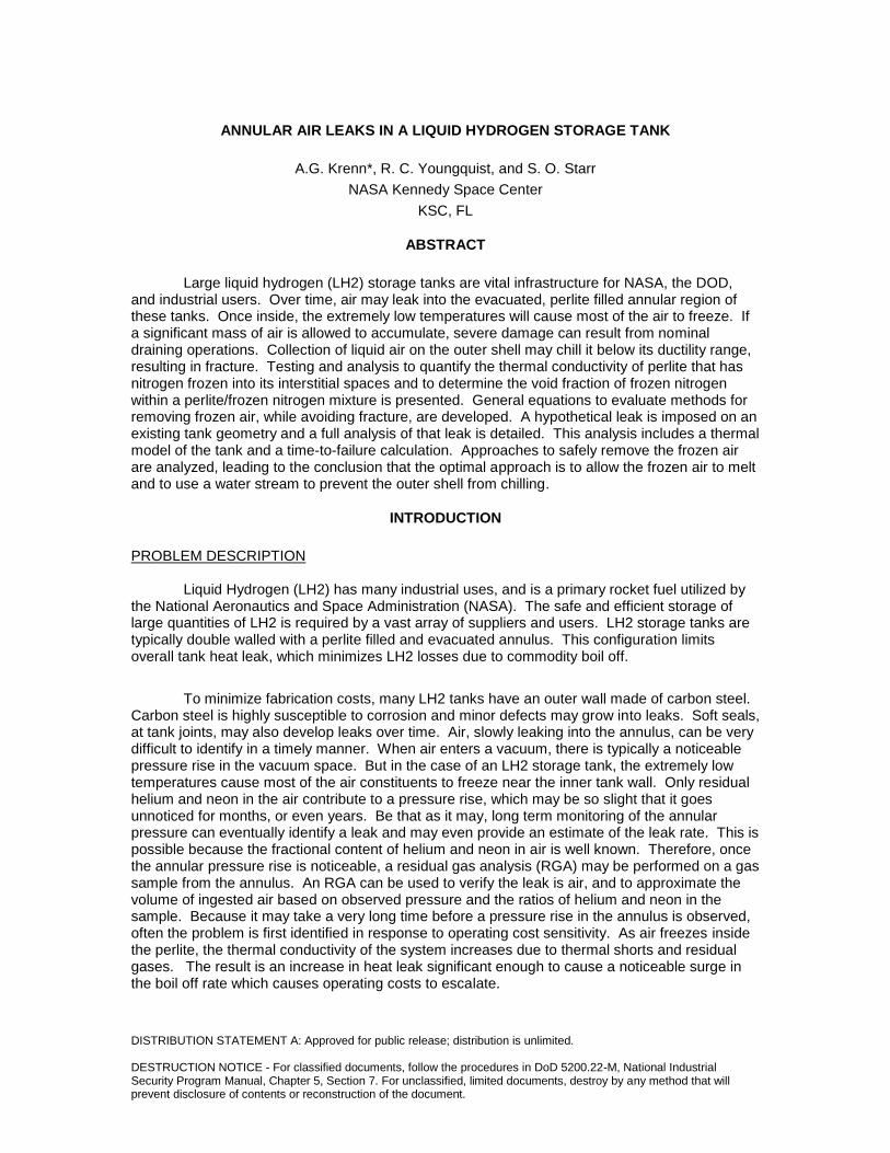
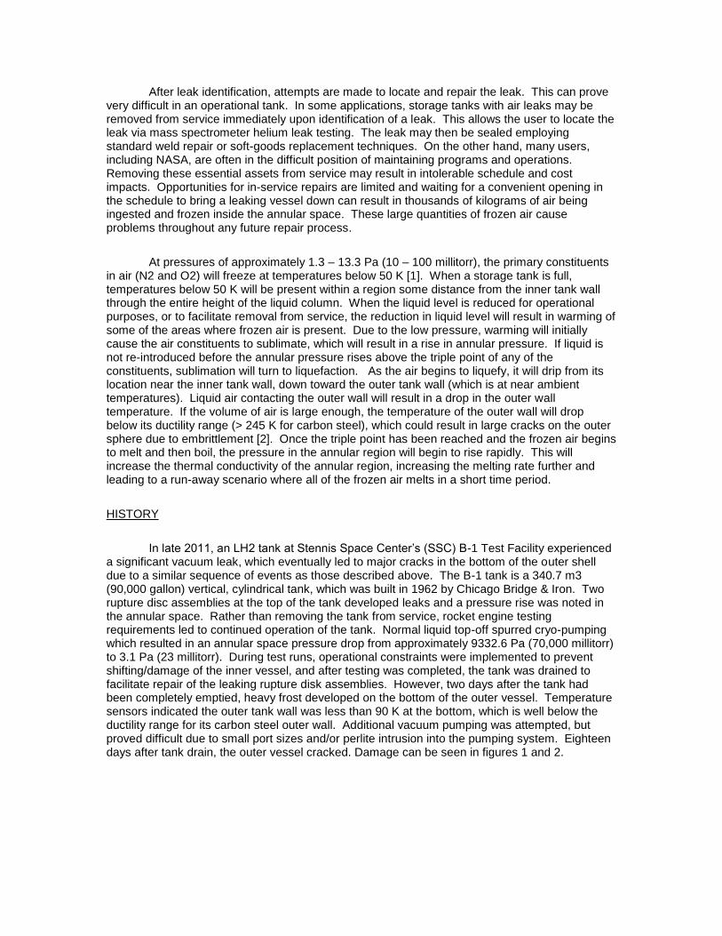
a significant vacuum leak, which eventually led to major cracks in the bottom of the outer shell due to a similar sequence of events as those described above. The B-1 tank is a 340.7 m3 (90,000 gallon) vertical, cylindrical tank, which was built in 1962 by Chicago Bridge & Iron. Two rupture disc assemblies at the top of the tank developed leaks and a pressure rise was noted in the annular space. Rather than removing the tank from service, rocket engine testing requirements led to continued operation of the tank. Normal liquid top-off spurred cryo-pumping which resulted in an annular space pressure drop from approximately 9332.6 Pa (70,000 millitorr) to 3.1 Pa (23 millitorr). During test runs, operational constraints were implemented to prevent shifting/damage of the inner vessel, and after testing was completed, the tank was drained to facilitate repair of the leaking rupture disk assemblies. However, two days after the tank had been completely emptied, heavy frost developed on the bottom of the outer vessel. Temperature sensors indicated the outer tank wall was less than 90 K at the bottom, which is well below the ductility range for its carbon steel outer wall. Additional vacuum pumping was attempted, but proved difficult due to small port sizes and/or perlite intrusion into the pumping system. Eighteen days after tank drain, the outer vessel cracked. Damage can be seen in figures 1 and 2.
Fig. 1. Photo of the B-1 tank with cracks Fig. 2. Bottom view of the B-1 tank with cracks
APPROACH
This paper will address methods to safely remove large quantities of frozen air from the
annulus of an LH2 storage tank. Testing to determine the thermal conductivity of perlite that has air frozen into its interstitial spaces was completed. The void fraction of solid nitrogen within a perlite/frozen nitrogen/vacuum mixture was determined using a mixing model. Equations were developed to determine if air can be safely removed by vacuum pumping or heating. Then, the acquired general information was used to analyze a specific tank geometry with a hypothetical leak. In order to accomplish this, a thermal model of the tank was created in SINDA/FLUINT. Using this thermal model with a void fraction estimate, an assumed ingested mass of air, and an assumed leak rate, the time-to failure can be estimated. Time-to-failure describes how long a tank may remain operational with an annular space air leak. When the time-to-failure has elapsed, the annular space will no longer be able to freeze the air, and the tank may enter a run-away failure scenario. Last, the generalized equations were used to perform a detailed engineering analysis of air removal techniques for the given hypothetical leak
EXPERIMENTAL DETERMINATION OF FROZEN NITROGEN/PERLITE PROPERTIES
In order to determine heat flow and time-scales, it is important to understand how the thermal conductivity of perlite is affected by the freezing of air into its interstitial spaces. Therefore, an experiment was developed to determine this value. Nitrogen was used in this experiment instead of air to simplify the analysis and avoid potential oxygen safety hazards. Because air is 78.1% nitrogen, this simplification is considered to be adequately representative of expected real-life thermal conductivity changes. Within a vacuum chamber, perlite was inserted between a 15 K surface and a 78 K radiation shield. GN2 was then slowly bled into the chamber and allowed to freeze into the interstitial spaces of the perlite. Temperature sensors placed within the perlite samples were used to determine the effective thermal conductivity of the perlite/frozen nitrogen mixture.
TEST SET-UP
A Cryomech AL230 Cold head was covered by 12.7 cm (5 in) of perlite. Eight silicon diode temperature sensors (Scientific Instruments Model 410AA) were installed in the center of the perlite at different elevations. The cold head/perlite sample was wrapped in a 3 m (10 ft.) long, 10 mm thick aerogel blanket. The silicon diode wires were sewn in place with Kevlar thread and wrapped inside the blanket. A radiation shield was fabricated from 0.318 cm (.125 in) copper
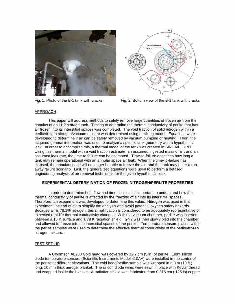
plate sandwiched by 0.635 cm (.25 in) copper tubing runs in a waffle pattern. The radiation shield, intended to minimize temperature gradient in the perlite sample, was positioned approximately 2 in. above the top of the perlite sample and was supplied with liquid nitrogen (LN2) from a feedthrough at the bottom of the vacuum chamber. Cold gaseous nitrogen (GN2) exited the radiation shield through a separate feedthrough, also at the bottom of the vacuum chamber which connected to a facility vent line. A multi-layer insulation (MLI) lined vacuum can was installed over the sample assembly. The vacuum chamber has three additional feedthroughs which were fully utilized. A tee was installed on one feedthrough where two electrical connectors attached to silicon diode wires. Lakeshore Quad-Twist cryogenic (QT-36) phosphor bronze wire was used to limit heat leak into the system. A second feedthrough was used to connect a vacuum pump, relief valve, and high/low pressure transducers. The third feedthrough was used to connect a 150 psi GN2 supply limited by a flow controller which was controlled by a feedback loop with the pressure transducers to allow a constant pressure to be maintained throughout the test. The complete test set-up is shown schematically in figure 3.
Fig. 3. Schematic of the test set-up
DATA COLLECTION/ANALYSIS
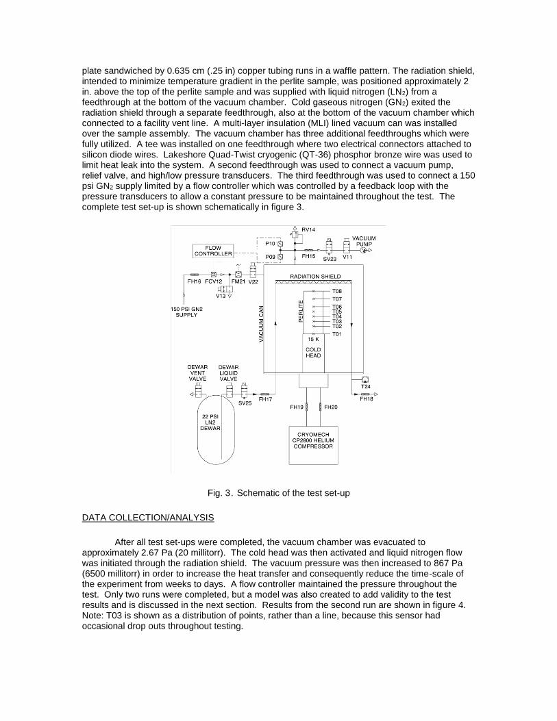
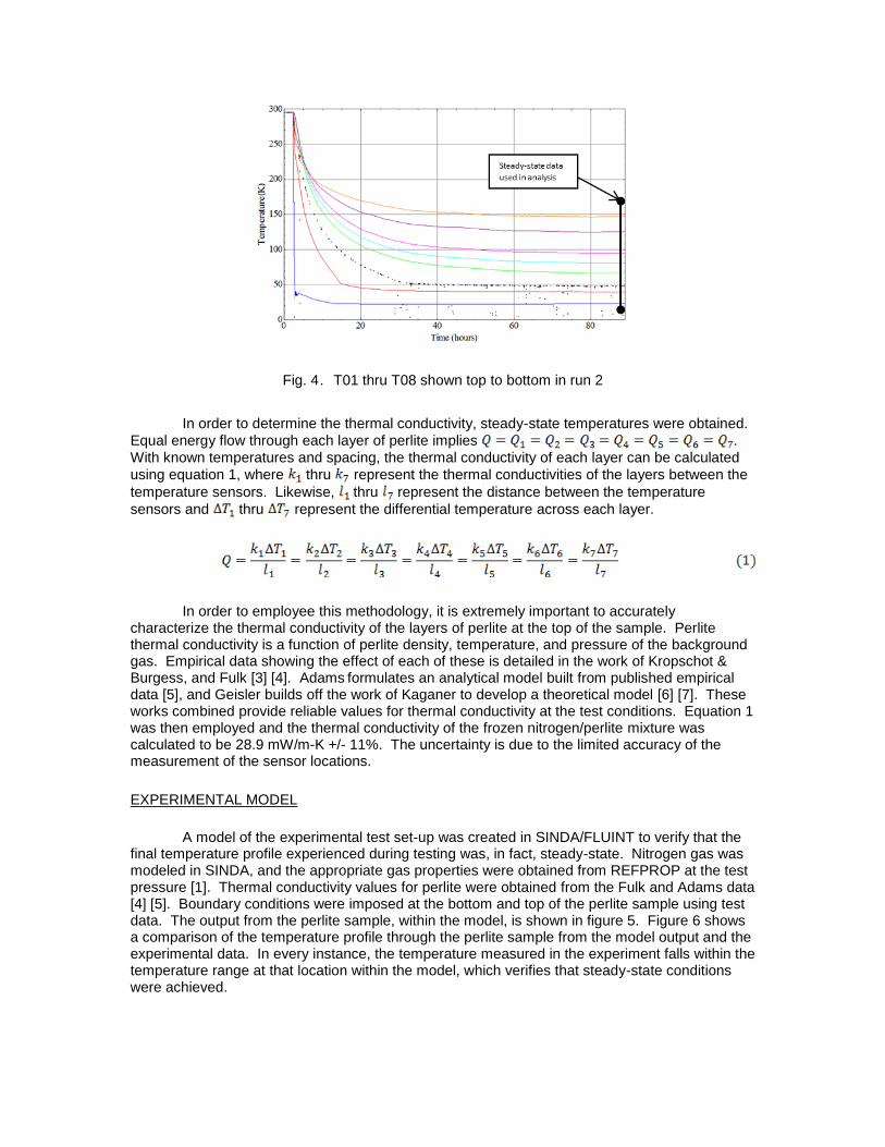
After all test set-ups were completed, the vacuum chamber was evacuated to approximately 2.67 Pa (20 millitorr). The cold head was then activated and liquid nitrogen flow was initiated through the radiation shield. The vacuum pressure was then increased to 867 Pa (6500 millitorr) in order to increase the heat transfer and consequently reduce the time-scale of the experiment from weeks to days. A flow controller maintained the pressure throughout the test. Only two runs were completed, but a model was also created to add validity to the test results and is discussed in the next section. Results from the second run are shown in figure 4. Note: T03 is shown as a distribution of points, rather than a line, because this sensor had occasional drop outs throughout testing.
Fig. 4. T01 thru T08 shown top to bottom in run 2
In order to determine the thermal conductivity, steady-state temperatures were obtained.
Equal energy flow through each layer of perlite implies .
With known temperatures and spacing, the thermal conductivity of each layer can be calculated
using equation 1, where thru represent the thermal conductivities of the layers between the
temperature sensors. Likewise, thru represent the distance between the temperature
sensors and thru represent the differential temperature across each layer.
In order to employee this methodology, it is extremely important to accurately characterize the thermal conductivity of the layers of perlite at the top of the sample. Perlite thermal conductivity is a function of perlite density, temperature, and pressure of the background gas. Empirical data showing the effect of each of these is detailed in the work of Kropschot & Burgess, and Fulk [3] [4]. Adams formulates an analytical model built from published empirical data [5], and Geisler builds off the work of Kaganer to develop a theoretical model [6] [7]. These works combined provide reliable values for thermal conductivity at the test conditions. Equation 1 was then employed and the thermal conductivity of the frozen nitrogen/perlite mixture was calculated to be 28.9 mW/m-K +/- 11%. The uncertainty is due to the limited accuracy of the measurement of the sensor locations.
EXPERIMENTAL MODEL
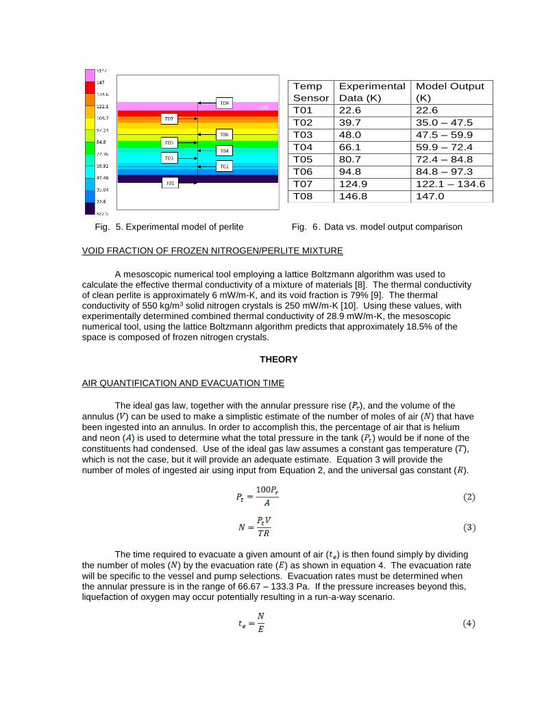
A model of the experimental test set-up was created in SINDA/FLUINT to verify that the final temperature profile experienced during testing was, in fact, steady-state. Nitrogen gas was modeled in SINDA, and the appropriate gas properties were obtained from REFPROP at the test pressure [1]. Thermal conductivity values for perlite were obtained from the Fulk and Adams data [4] [5]. Boundary conditions were imposed at the bottom and top of the perlite sample using test data. The output from the perlite sample, within the model, is shown in figure 5. Figure 6 shows a comparison of the temperature profile through the perlite sample from the model output and the experimental data. In every instance, the temperature measured in the experiment falls within the temperature range at that location within the model, which verifies that steady-state conditions were achieved.
Fig. 5. Experimental model of perlite Fig. 6. Data vs. model output comparison
VOID FRACTION OF FROZEN NITROGEN/PERLITE MIXTURE
A mesoscopic numerical tool employing a lattice Boltzmann algorithm was used to calculate the effective thermal conductivity of a mixture of materials [8]. The thermal conductivity of clean perlite is approximately 6 mW/m-K, and its void fraction is 79% [9]. The thermal conductivity of 550 kg/m3 solid nitrogen crystals is 250 mW/m-K [10]. Using these values, with experimentally determined combined thermal conductivity of 28.9 mW/m-K, the mesoscopic numerical tool, using the lattice Boltzmann algorithm predicts that approximately 18.5% of the space is composed of frozen nitrogen crystals.
THEORY
AIR QUANTIFICATION AND EVACUATION TIME
The ideal gas law, together with the annular pressure rise ( ), and the volume of the
annulus ( ) can be used to make a simplistic estimate of the number of moles of air ( ) that have
been ingested into an annulus. In order to accomplish this, the percentage of air that is helium
and neon ( ) is used to determine what the total pressure in the tank ( ) would be if none of the
constituents had condensed. Use of the ideal gas law assumes a constant gas temperature ( ),
which is not the case, but it will provide an adequate estimate. Equation 3 will provide the
number of moles of ingested air using input from Equation 2, and the universal gas constant ( ).
The time required to evacuate a given amount of air ( ) is then found simply by dividing
the number of moles ( ) by the evacuation rate ( ) as shown in equation 4. The evacuation rate
will be specific to the vessel and pump selections. Evacuation rates must be determined when the annular pressure is in the range of 66.67 – 133.3 Pa. If the pressure increases beyond this, liquefaction of oxygen may occur potentially resulting in a run-a-way scenario.
Temp
Sensor
Experimental
Data (K)
Model Output
(K)
T01 22.6 22.6
T02 39.7 35.0 – 47.5
T03 48.0 47.5 – 59.9
T04 66.1 59.9 – 72.4
T05 80.7 72.4 – 84.8
T06 94.8 84.8 – 97.3
T07 124.9 122.1 – 134.6
T08 146.8 147.0
LEAK RATE DETERMINATION
Armed with the number of moles of air inside the annulus, a straightforward determination of the leak rate can be made, assuming the air accumulation time is known. Proper maintenance of large LH2 storage tanks typically includes routine vacuum monitoring, so this data should be readily available. The mass of the ingested air, which is found by multiplying the number of
ingested moles ( ) by the molar mass of air ( ), divided by the density of air ( ) and the air
accumulation time ( ), yields leak rate ( ) as shown in Eqn. 5.
TANK HEAT LEAK AND MELTING TIME
The heat leak into the tank ( ) can be computed by multiplying the boil off rate ( ) by the
heat of vaporization of the boiling commodity ( ). For the case of LH2, where the boil off rate
is known in gallons per day, the heat leak in kW can be determined using equation 6.
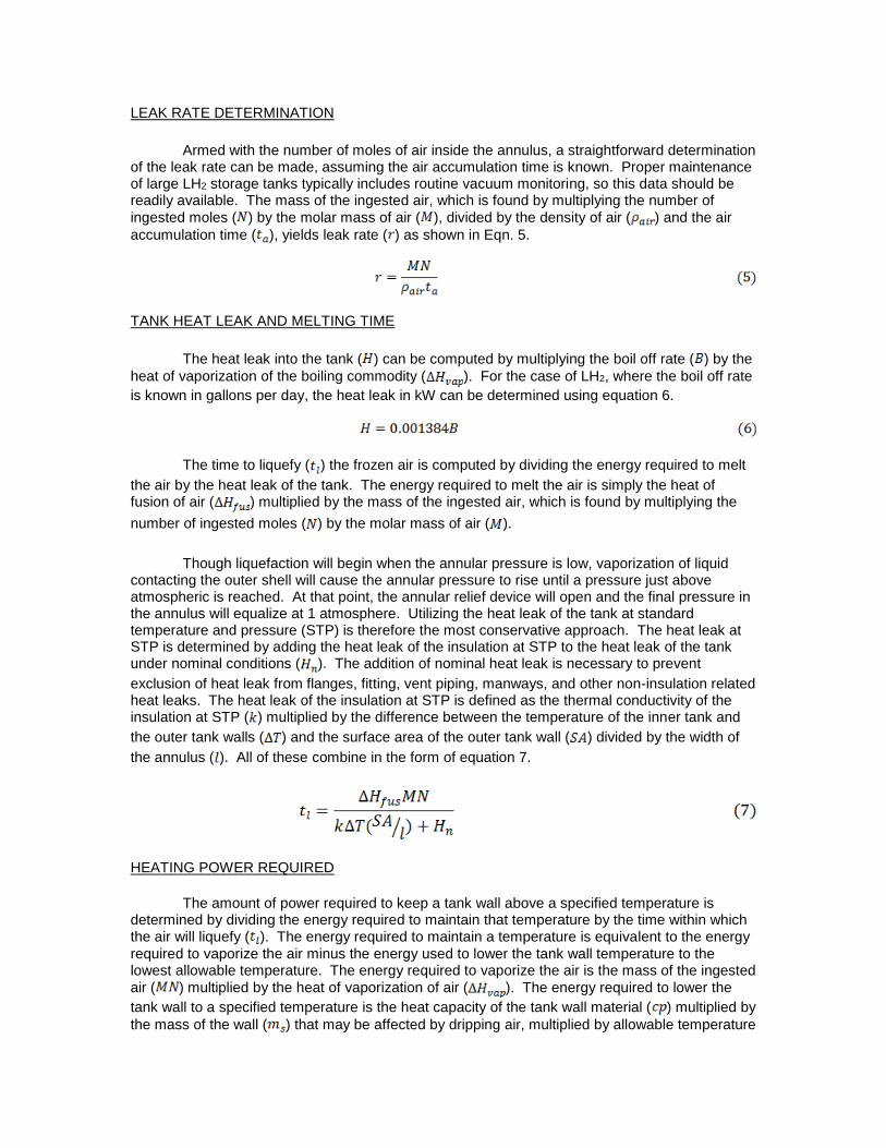
The time to liquefy ( ) the frozen air is computed by dividing the energy required to melt
the air by the heat leak of the tank. The energy required to melt the air is simply the heat of fusion of air ( ) multiplied by the mass of the ingested air, which is found by multiplying the
number of ingested moles ( ) by the molar mass of air ( ).
Though liquefaction will begin when the annular pressure is low, vaporization of liquid
contacting the outer shell will cause the annular pressure to rise until a pressure just above atmospheric is reached. At that point, the annular relief device will open and the final pressure in the annulus will equalize at 1 atmosphere. Utilizing the heat leak of the tank at standard temperature and pressure (STP) is therefore the most conservative approach. The heat leak at STP is determined by adding the heat leak of the insulation at STP to the heat leak of the tank under nominal conditions ( ). The addition of nominal heat leak is necessary to prevent
exclusion of heat leak from flanges, fitting, vent piping, manways, and other non-insulation related heat leaks. The heat leak of the insulation at STP is defined as the thermal conductivity of the insulation at STP ( ) multiplied by the difference between the temperature of the inner tank and
the outer tank walls ( ) and the surface area of the outer tank wall ( ) divided by the width of
the annulus ( ). All of these combine in the form of equation 7.
HEATING POWER REQUIRED
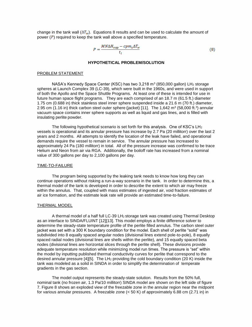
The amount of power required to keep a tank wall above a specified temperature is determined by dividing the energy required to maintain that temperature by the time within which the air will liquefy ( ). The energy required to maintain a temperature is equivalent to the energy
required to vaporize the air minus the energy used to lower the tank wall temperature to the lowest allowable temperature. The energy required to vaporize the air is the mass of the ingested
air ( ) multiplied by the heat of vaporization of air ( ). The energy required to lower the
tank wall to a specified temperature is the heat capacity of the tank wall material ( ) multiplied by
the mass of the wall ( ) that may be affected by dripping air, multiplied by allowable temperature
change in the tank wall ( ). Equations 8 results and can be used to calculate the amount of
power ( ) required to keep the tank wall above a specified temperature.
HYPOTHETICAL PROBLEM/SOLUTION
PROBLEM STATEMENT
NASA’s Kennedy Space Center (KSC) has two 3,218 m3 (850,000 gallon) LH2 storage spheres at Launch Complex 39 (LC-39), which were built in the 1960s, and were used in support of both the Apollo and the Space Shuttle Programs. At least one of these is intended for use in future human space flight programs. They are each comprised of an 18.7 m (61.5 ft.) diameter 1.75 cm (0.688 in) thick stainless steel inner sphere suspended inside a 21.6 m (70 ft.) diameter, 2.95 cm (1.16 in) thick carbon steel outer sphere (jacket) [11]. The 1,642 m3 (58,000 ft.3) annular vacuum space contains inner sphere supports as well as liquid and gas lines, and is filled with insulating perlite powder.
The following hypothetical scenario is set forth for this analysis. One of KSC’s LH2
vessels is operational and its annular pressure has increase by 2.7 Pa (20 millitorr) over the last 2 years and 2 months. All attempts to identify the location of the leak have failed, and operational demands require the vessel to remain in service. The annular pressure has increased to approximately 24 Pa (180 millitorr) in total. All of the pressure increase was confirmed to be trace Helium and Neon from air via RGA. Additionally, the boiloff rate has increased from a nominal value of 300 gallons per day to 2,100 gallons per day.
TIME-TO-FAILURE
The program being supported by the leaking tank needs to know how long they can continue operations without risking a run-a-way scenario in the tank. In order to determine this, a thermal model of the tank is developed in order to describe the extent to which air may freeze within the annulus. That, coupled with mass estimates of ingested air, void fraction estimates of air ice formation, and the estimate leak rate will provide an estimated time-to-failure.
THERMAL MODEL
A thermal model of a half full LC-39 LH2 storage tank was created using Thermal Desktop
as an interface to SINDA/FLUINT [12][13]. This model employs a finite difference solver to determine the steady-state temperature profile of the perlite filled annulus. The carbon steel outer jacket was set with a 300 K boundary condition for the model. Each shell of perlite “solid” was subdivided into 8 equally spaced angular nodes (divisional lines extend pole-to-pole), 8 equally spaced radial nodes (divisional lines are shells within the perlite), and 15 equally spaced beta nodes (divisional lines are horizontal slices through the perlite shell). These divisions provide adequate temperature resolution while minimizing model run times. The pressure is “set” within the model by inputting published thermal conductivity curves for perlite that correspond to the desired annular pressure [4][5]. The LH2 providing the cold boundary condition (20 K) inside the tank was modeled as a solid in SINDA in order to simplify the determination of temperate gradients in the gas section.
The model output represents the steady-state solution. Results from the 50% full,
nominal tank (no frozen air, 1.3 Pa/10 millitorr) SINDA model are shown on the left side of figure 7. Figure 8 shows an exploded view of the freezable zone in the annular region near the midpoint for various annular pressures. A freezable zone (< 50 K) of approximately 6.88 cm (2.71 in) in
thickness is shown to extend the entire height of the liquid. It begins to taper off at the upper limit of the liquid and diminishes to zero thickness approximately 79.2 cm (2.6 ft.) above the liquid line. Results show that at steady-state and 50% full, approximately 38.2 m3 (1,350 ft3) of annular space is cold enough to freeze air. This value corresponds to 2.3% of the total annular volume. Results from the model of a tank which has leaked enough air to increase the annular pressure to 24 Pa (180 millitorr) is shown on the right side of figure 7. This model uses the experimentally determined thermal conductivity of perlite/frozen nitrogen mixture as an input, and consequently, the freezable zone expands to approximately 22.6 cm (8.9 in) in thickness or 7.8% of the total annular volume.
The model provides maximum boundaries for the location of the air-ice under varying
conditions. As air leaks in, there is a pressure increase due to residual helium and neon that will work to shrink the freezable zone, and there is a reverse effect from the increase in thermal conductivity due to the condensation of air. The net effect of these two opposing mechanisms is to increase the freezable zone until approximately 26.7 Pa (200 millitorr). Above that pressure the increase in thermal conductivity due to residual gases causes the freezable zone to recede. Figure 8 shows how the freezable zone changes with pressure in a 50% full tank.
The maximum extent of the freezable zone is important because once the available
volume is filled, there will be nowhere for additional leaking air to freeze, which will cause the pressure will climb at a much higher rate. As discussed previously, when the pressure increases above the triple point for oxygen, warming will cause the frozen oxygen to melt. The tank may then enter a run-away scenario in which rapid liquefaction of the frozen air may result in outer sphere cracks. As figure 8 shows, the freezable zone begins to recede after 26.7 Pa (200 millitorr) of pressure is reached.
Fig. 7. Thermal model (50% full): 10 millitorr (left); Fig. 8. Changes in freezable zone with 180 millitorr w/air-ice (right) changes in pressure TIME-TO-FAILURE SOLUTION
In order to determine the time-to-failure, the thermal model is used to determine the
maximum portion of the annulus that may freeze air. As noted in the previous section, a zone extending 22.6 cm (8.9 in) from the inner tank wall is cold enough to hold air in the frozen form when the annular pressure is 24 Pa (180 millitorr). If the storage tank is full, that results in a volume of approximately 225 m3 (7,950 ft3). The fraction of solid nitrogen crystals within that space is approximately 18.5%, which means up to 42 m3 (1,500 ft3) of nitrogen can be frozen in the perlite around the inner tank. Because the density of solid nitrogen is 550 kg/m3, the annular space may hold at most, 23,000 kg of solid nitrogen. That much nitrogen, frozen from air, would result in an annular pressure rise to 31 Pa (230 millitorr) due to residual helium and neon that remain in the gaseous state. Assuming a constant leak rate of approximately 55 sccs
(calculated using equation 5), it will take approximately 3.6 years to leak enough air into the tank to increase the pressure from 180 millitorr to 230 millitorr.
The time-to-failure can be extended significantly by periodically evacuating the annular
space to maintain a pressure near 2.7 Pa (20 millitorr). In this case, the freezable zone increases to 626 m3, equating to a maximum of nearly 64,000 kg of frozen air. It would take more than 20 years to leak in that much air at a constant rate of 55 sccs. While evacuation of residual gas is a convenient way to extend a tank’s operational status, it would not alleviate the issue entirely. To begin with, structural stress calculations may be required to ensure the inner tank support structure can carry the additional weight of the air. Additionally, when the tank is eventually drained for refurbishment, the likelihood of over-chilling the outer tank wall multiplies due to the increase in the liquid mass to be vaporized. Much more heat input will be required to prevent crack formation in the outer wall.
SAFE REMOVAL ANALYSIS
This section discusses the options available to prevent the outer tank wall temperature from dropping below the ductility range in the event that the LH2 in the tank is completely and rapidly drained shortly after identification of the problem. A partial drain would increase the time-scales resulting in less power input required. The first option discussed is to use pumps to remove the sublimating frozen air, keeping the annular region pressure below the triple point so that no liquid is formed. The second method considered is to allow the frozen air to rapidly melt and apply heat to the outer tank to prevent it from chilling below its ductility temperature.
PUMPING METHOD
The 3,218 m3 (850,000 gallon) LH2 storage tank at LC-39B was removed from service at
the end of the Space Shuttle Program. The tank had been experiencing an abnormally high boiloff, so the annular region was backfilled with GN2, and investigated. The cause of the high heat leak was confirmed to be a perlite void in the annular region. The perlite void was filled with new perlite and other refurbishment activities ensued [14]. A pump-down log was kept during re-establishment of the annular vacuum, enabling determination of evacuation rates. The evacuation rates were then used to ascertain the amount of time it would take to remove the given mass of air.
The predominant two constituents of air are nitrogen and oxygen. They have triple points
of approximately 63 K / 12.5 kPa (94,000 millitorr) and 54 K / 0.15 kPa (1,100 millitorr) respectively. It is therefore necessary to maintain the annular pressure at or below approximately 133.3 Pa (1,000 millitorr) in order to prevent the frozen air from liquefying as it warms. Data from the LC-39B pump down logs show an evacuation rate of 1.5 – 1.7 Pa (11-13 millitorr) per hour when pumping in the 133.3 – 60 Pa (1,000 – 450 millitorr) range. The volume of the annular space is known, and the tank was at ambient temperatures during the evacuation. Using the ideal gas law, the evacuation rate was determined to be approximately 1 mole per hour.
Historically, the evacuated LC-39A and LC-39B tank pressure was 1.3 – 2.7 Pa (10 - 20
millitorr) when the tanks were full of LH2. Therefore, 2.7 Pa (20 millitorr) will be considered a baseline pressure for the analysis, reducing the pressure requiring removal from the annular space from 24 Pa (180 millitorr) to 21.3 Pa (160 millitorr). Helium and neon account for 5.24 parts per million (PPM) and 18.18 PPM of air respectively (0.002342% combined). The 21.3 Pa (160 millitorr) of He and Ne must then represent a pressure of 911,000 Pa (132 psia) of air under ambient conditions. The volume of annulus is known (1636.74 m3), and the temperature of the sample is ambient, so the ideal gas law can be employed to determine that 21.3 Pa (160 millitorr) of He and Ne suggest that 612,000 moles of air are present in the annulus. With continuous pumping at a rate of 1 mole per hour, it would take nearly 70 years to evacuate the air and maintain the pressure below 133.3 Pa (1,000 millitorr). That is clearly not practical. Consequently, this option is deemed non-feasible.
HEATING METHOD The LH2 storage tank has a boiloff rate of approximately 563 kg/day (2,100 gallons/day).
The heat of vaporization of LH2 at 1 atmosphere is 446 kJ/kg, therefore, 251 MJ/day (2.91 kW) must be coming into the system. The heat of fusion of N2 and O2 is 25.7 kJ/kg, and 13.9 kJ/kg respectively. Weighting these values by percentage of each in air results in a value of 23.2 kJ/kg for the heat of fusion of air. 612,000 moles of air (calculated above) translates to 17,700 kg of air. In order to establish a minimum time in which the air could melt, the heat leak at standard temperature and pressure (STP) is considered. The thermal conductivity of perlite at STP is 54 mW/m-K [5]. The surface area of the outer tank wall is 1,430 m2, and the annulus is 1.3 m thick [11]. Therefore, the heat leak into the tank at STP due through the perlite is approximately 16.7 kW. Adding 0.4 kW to account for additional heat leak from flanges, access ports, etc. results in a total worst case heat leak of 17.1 kW at STP. 17.1 kW could melt 17,700 kg of air in approximately 6.7 hours if the heat were used exclusively to convert the frozen air to liquid air. Though this is not the case, a conservatively low time estimate is required to determine the maximum heat input required, so 6.7 hours will be used in subsequent analysis.
The heat of vaporization of air is 201.4 kJ/kg, so it would take 3,570 MJ to vaporize the
entire 17,700 kg mass of liquid air. However, the temperature of the outer jacket may be allowed to drop, as long as it remains above the ductility limit of the carbon steel (245 K). A temperature of 275 K is used in the analysis to prevent the formation of frost on the surface, which would act as an insulator. The liquid air can only contact the outer wall as gravity allows. Dripping air will be able to contact 374 m2 of the jacket, which equates to a carbon steel volume of 11 m3. The density of carbon steel is 7,850 kg/m3 and the heat capacity is 0.49 kJ/kg-K, so the energy required to lower 11 m3 of outer tank wall from 300 K to 275 K is 1,060 MJ. Subtracting that from the total 3,570 MJ required to vaporize the liquid leaves 2,510 MJ which must be added to the tank in order to vaporize the liquid and keep the outer shell at or above 275 K. Because this liquid may form in as little as 6.7 hours, 376 MJ/hr or 104 kW (distributed over 374 m2) will be required to keep the outer wall in a safe temperature range during the melting/vaporization process.
Because the outer tank wall is 2.95 cm (1.16 in.) thick, the question remains, if the
outside of the outer wall can be kept above the freezing temperature of water, can cold spots below the ductility range of carbon steel still form on the inside of the outer tank wall? In order to answer this question, SINDA/FLUINT was used to model a 16 m2 section of outer tank wall. The outside of the wall was set at a constant temperature of 275 K. Next, the 104 kW load on the inside of the wall was divided into equivalent 16 m2 portions (4.5 kW). The 4.5 kW cooling load was then concentrated on the 16 m2 sample plate (with a constant heat distribution), representing a stream of liquid air contacting a small portion of the inside of the wall. Temperatures on the inside of the wall did not reach 245 K until the load area was reduced to 232 cm2 (36 in.2). This suggests that while it is possible to have very small areas of the inner surface below the ductility range while the entire outer surface is above the freezing point of water, the likelihood of that happening is very low because all of the liquid would need to be coursing to the inner surface in extremely narrow and focused streams, which is highly unlikely.
Before analyzing methods to add 104 kW of heat over 374 m2 of tank wall, it is important
to note electrical and heating restrictions. The tank in question holds up to 850,000 gallons of liquid hydrogen. Therefore, a distance 7.62 m (25 ft.) from the outer tank wall is classified as Class 1 Division 2 and all electronics within this zone must have sealed connections and surge protection [15][16]. Additionally, the exposed surface of a heater may not exceed 80% of the autoignition temperature of the hydrogen (773 K). Therefore, any hot surface entering that area may not exceed 618 K.
Several methods of adding heat were considered. Polyimide heaters bonded directly to
the tank wall would provide more than enough heating power, but between 140 – 280 heaters
would be required (depending on heater size and set point) in order to distribute the heat over the entire 374 m2 of tank wall without leaving cold spots between the heaters. Blowing warm air across the surface of the tank with fans would also provide enough heating power. However, wind conditions may counter-act the effects in some locations, other locations may be difficult to reach, and fans would be required at elevation in order to provide the coverage required. Infrared heaters also provide sufficient heating power, but do not meet Class 1 Division 2 maximum temperature requirements. Consequently, they would need to be placed 7.62 m (25 ft.) away from the tank wall. While they can still provide adequate heating from this distance, there would likely be significant gaps in coverage due to obstructions lying between the heaters and the tank wall. The optimal heating solution is the spraying of water onto the outer tank wall. This method provides adequate heating, causes no increase in hazard, sufficiently covers all areas, and imposes only minimal implementation costs. The following section details the analysis and design for a spray water heating system at LC-39B.
WATER HEATING ANALYSIS/DESIGN
In order to determine the potential effectiveness of spraying water, it is first necessary to determine the amount of water that would be required to achieve adequate heating. The minimum temperature acceptable for the storage sphere’s outer wall is 275 K. Assuming the ambient water temperature is 300 K, the water may be chilled by a maximum of 25 K when contacting the outer tank wall. The specific heat of water is approximately 4.19 kJ/kg-K. The specific heat multiplied by the temperature change shows that it would take 105 kJ to reduce 1 kg of water by 25 K. As previously determined, 376 MJ/hour must be added to the tank to keep the wall temperature from dropping below 275 K. 376 MJ/hour divided by 105 kJ/kg shows that 3,600 kg of water must be sprayed on the tank every hour if all of the water is chilled to 275 K. Using the density of water (1000 kg/m3) and converting units yields 16 gallons per minute of water must be continuously applied to the tank for the entire 6.7 hours in order to keep the wall temperature above 275 K. 16 gallons per minute represents a minimum value because it assumes all of the water is chilled to the maximum extent. If, instead, it is assumed that the water is only chilled by 1 Kelvin when applied to the cold tank, the same methodology results in a water flow rate requirement of 400 gallons per minute. Many factors will affect how much the water will chill when contacting the outer wall, but the flow rate of 400 gallons per minute represents an adequate upper bound.
Next, it is necessary to evaluate the existing water capability on-site at the LH2 tank.
Drawings detailing the existing water deluge system at launch pad LC-39 B show 10 risers surrounding the LH2 sphere, each spaced 36 degrees apart from the tank’s center-line [17]. Each riser has 3 water flow nozzles, (1) 10 feet from grade, (1) 30 feet from grade, and (1) 50 feet 10 inches from grade. The top nozzle extends 13 feet 10 inches above the equator of the tank. Additionally, there are 4 nozzles located below the tank and are directed up to contact the very bottom of the tank. In total, there are 34 nozzles with flow rates of 94 – 240 gallons per minute. There is no way to activate only a portion of nozzles, so activating the system will release water at a flow rate of 5,580 gallons per minute and that water will completely cover the potentially effected zone. This water is drawn from (2) 1.4 million gallon water reservoirs. If both reservoirs are filled to capacity prior to operations, water may flow continuously for up to 8.3 hours.
Activating the water deluge system will release 5,580 gallons per minute of water, but no
more than 400 gallons per minute is required to keep the outer tank wall adequately warm. In order to reduce the flowrate, the existing nozzles could be replaced with new, lower flow rate nozzles, but that would require procurement and labor. Alternatively, the 8 inch manual butterfly valve that acts as a system shut-off valve could be modulated as required to reduce the flow on the tank while visually verifying no ice builds up on the outer tank wall. This option would require no procurements or system modifications, but could become labor intensive if the tank’s warming process is prolonged. The recommended solution is to partially open the shut-off valve so that full flow is not achieved, while ensuring appropriate water contact with the outer tank wall surface. Then, the remotely operated 8 inch butterfly valve should be cycled opened and closed from the
control room to ensure no ice forms on the surface of the tank. This solution requires no system modifications, and only has minor labor impacts.
SUMMARY AND CONCLUSIONS
Liquid hydrogen tanks that develop air leaks into their annulus can put users into a very difficult position. If significant quantities of air have been ingested into the annulus, attempts to drain and repair the tank can have detrimental effects. The purpose of this work is to characterize some of the physical changes that occur within the system due to an air leak, and to determine the best way to safely remove the ingested air. The thermal conductivity and void fraction of the frozen nitrogen/perlite mixture was determined through testing and analysis. Generalized equations were developed to allow any LH2 tank operator to evaluate the severity of the situation and determine the heating requirements to prevent severe damage of the storage tank. A specific leak scenario was then proposed and evaluated. A thermal model of the proposed tank was developed and used to estimate the length of time the tank could remain operational with the proposed leak. Methods to safely remove the air were evaluated, and the most practical approach for the proposed case was determined to be the use of an in-place water deluge system. The specific case solution can be applied to either of the LC-39 LH2 tanks at KSC, and the generalized equations developed in the theory section can be used to evaluate any other leaking LH2 tank.
ACKNOWLEDGMENTS
This work was supported by the Rocket Propulsion Test Program [Technical Task Agreement RPT-7615-TD01]; the Ground Systems Development and Operations Program; the Florida Space Grant Consortium; and the Advanced Exploration Systems Program.
A special thanks to Jared Sass for fervently supporting this work through every stage. Craig Fortier and Jared Congiardo were instrumental while working with SINDA/FLUINT. Testing would not have been possible without the support of Kevin Jumper, James Fesmire and the team of the Cryogenics Test Laboratory. Bartt Hebert, Harry Ryan, and Haynes Haselmaier produced an unpublished overview of the events that took place at Stennis Space Center that provided important details in understanding the air leak problem. Dr. Mark Nurge contributed to data analysis, and Jose Perotti provided instrumentation for testing. Dr. Aniket Bhattacharya and Coleman Cariker at UCF provided valuable feedback throughout and completed yet unpublished work to determine the nitrogen ice density estimates.
REFERENCES
1. Lemmon, E. W., Huber, M. L., & McLinden, M. O., Reference Fluid Thermodynamic and
Transport Properties (REFPROP), NIST Standards Database 23, Version 9.1. (2013). 2. Mittal, P. Part 2: Low temperature ductility and ductile crack arrest properties of high strength low alloy steel. Pipeline & Gas Journal 238. (2011). 3. Kropschot, R. H., & Burgess, R. W. Perlite for cryogenic insulation. Advances in Cryogenic Engineering 8, (pp. 425-436). (1963). 4. Fulk, M. M. Evacuated powder insulation for low temperatures. Progress in Cryogenics, 65-84. (1959). 5. Adams, L. Thermal conductivity of evacuated perlite. Cryogenic Technology, 1(6), 249-251. (1965). 6. Geisler, M. Thermal Characterization by freezing of carbon dioxide as a filler gas. Wurzburg, Germany: Dissertation to the Department of Physics and Astronomy at the University of Wurzburg. (2010). 7. Kaganer, M. G. Thermal insulation in cryogenic engineering. Israel Program for Scientific Translations. (1969). 8. Wang, M., Wang, J., Pan, N., & Chen, S. Mesoscopic predictions of the effective thermal conductivity for microscale random porous media. Physical Review E, 75(3), 036702. (2007).
9. Celik, A. G., Kilic, A. M., & Cakal, G. O. Expanded perlite aggregate characterization for use as a lightweight construction raw material. Physicochemical Problems of Mineral Processing, 49(2), 689-700. (2013). 10. Konstantinov, V. A., Manzhelii, V. G., Revyakin, V. P., & Sagan, V. V. Isochoric thermal conductivity of solid nitrogen. Low Temperature Physics Vol. 31, 419-422. (Dec. 2005). 11. Chicago Bridge & Iron. Drawing number LHCD-40862. General Plan 850 MG LH2 Sphere. Launch Complex 39-B: Catalytic Co. (1965). 12. C&R Technologies. (May 2013). SINDA/FLUINT User's Manual. SINDA/FLUINT General Purpose Thermal/Fluid Network Analyzer Version 5.6. (May 2013). 13. C&R Technologies. Thermal Desktop User's Manual, Version 5.7. (2014). 14. Krenn, A. G. Diagnosis of a poorly performing liquid hydrogen bulk storage sphere. Advances in Cryogenic Engineering: Transactions of the Cryogenic Engineering Conference (pp. 376-383). Spokane, WA: AIP. (2012). 15. NFPA 70. National Electric Code. National Fire Protection Association. (2014). 16. NFPA 497. Recommended practice for the classification of flammable liquids, gases, or vapors and of hazardous (classified) locations for electrical installations in chemical process areas. National Fire Protection Association. (2012). 17. Jones, Edmunds, & Associates, Inc. Drawing number 79K33941. Modernize firex water system LC 39 B. (1997).