Abstract The paper describes the development of a virtual vehicle system using virtual prototyping computer tools. The virtual vehicle is used for the prediction of the structural dynamics. Since the modelling process for complete rail vehicle systems becomes increasingly more complex, time and cost can be saved by the use of a database concept and an automated assembling process for the vehicle of interest. Supported by a modular design concept, vehicle components for a metro train have been modelled and stored as substructures in a specific vehicle component database. Using this database, train configurations up to a three-car train can be assembled very quickly to perform structural dynamics analyses and to predict the ride comfort. Experimental results have been compared with simulation results of the rail vehicle to improve the modelling technique and the accuracy of the developed virtual vehicle system. The mathematical modelling of the rail vehicle system featuring elastic components, the structure of the database as well as numerical and experimental results are shown in the paper. 1 Introduction Since cities are growing and people are becoming more busy, urban transport systems have to improve. Vehicle manufacturers are investing to raise the travelling speed, to increase the passenger capacity of the vehicles, as well as to provide better passenger comfort [4]. With the use of advanced lightweight structures for the vehicle design, structural dynamics in connection with vehicle running dynamics is increasingly important. In the field of vehicle development, objectives that are driven by the competition, like to shorten the time to market, to create innovative designs, and to lower the vehicle costs, are forcing the vehicle engineers to use new development methods. Virtual prototyping computer tools have made considerable progress in recent years. They are widely used for modelling and simulating the dynamic motion of complex vehicle systems [5]. Working with virtual prototyping technology has shown potential to improve the product development process. The paper describes work done by Siemens using virtual prototyping computer tools. New rail vehicle designs have been modelled and the dynamic motion of complex moving structures has been simulated. The virtual vehicle developed is used for the optimisation of the ride comfort of future metro trains by numerical simulation. As an example for the use of the developed software tool, the virtual system of a metro train will be discussed. The following issues will be addressed: ! The modelling done for the structural dynamics analyses. ! The structure of the new developed database. ! The automated generation of the virtual metro. ! Numerical results predicting the structural dynamics and the ride comfort of the new developed vehicle system. The work described has been done using the computer tools I-deas, Abaqus and Simpack. The numerical results have been compared to the results of experimental modal analyses and measurements of the ride comfort using a real prototype vehicle. See Fig. 1. Figure 1: New metro for Vienna.
Transcript
Abstract
The paper describes the development of a virtual vehiclesystem using virtual prototyping computer tools. The virtualvehicle is used for the prediction of the structural dynamics.Since the modelling process for complete rail vehiclesystems becomes increasingly more complex, time and costcan be saved by the use of a database concept and anautomated assembling process for the vehicle of interest.
Supported by a modular design concept, vehicle componentsfor a metro train have been modelled and stored assubstructures in a specific vehicle component database.Using this database, train configurations up to a three-cartrain can be assembled very quickly to perform structuraldynamics analyses and to predict the ride comfort.
Experimental results have been compared with simulationresults of the rail vehicle to improve the modelling techniqueand the accuracy of the developed virtual vehicle system.
The mathematical modelling of the rail vehicle systemfeaturing elastic components, the structure of the database aswell as numerical and experimental results are shown in thepaper.
1 Introduction
Since cities are growing and people are becoming more busy,urban transport systems have to improve. Vehiclemanufacturers are investing to raise the travelling speed, toincrease the passenger capacity of the vehicles, as well as toprovide better passenger comfort [4]. With the use ofadvanced lightweight structures for the vehicle design,structural dynamics in connection with vehicle runningdynamics is increasingly important.
In the field of vehicle development, objectives that are drivenby the competition, like to shorten the time to market, tocreate innovative designs, and to lower the vehicle costs, areforcing the vehicle engineers to use new developmentmethods. Virtual prototyping computer tools have madeconsiderable progress in recent years. They are widely usedfor modelling and simulating the dynamic motion of complexvehicle systems [5]. Working with virtual prototyping
technology has shown potential to improve the productdevelopment process.
The paper describes work done by Siemens using virtualprototyping computer tools. New rail vehicle designs havebeen modelled and the dynamic motion of complex movingstructures has been simulated. The virtual vehicle developedis used for the optimisation of the ride comfort of futuremetro trains by numerical simulation.
As an example for the use of the developed software tool, thevirtual system of a metro train will be discussed. Thefollowing issues will be addressed:
! The modelling done for the structural dynamicsanalyses.
! The structure of the new developed database.! The automated generation of the virtual metro.! Numerical results predicting the structural dynamics
and the ride comfort of the new developed vehiclesystem.
The work described has been done using the computer toolsI-deas, Abaqus and Simpack. The numerical results havebeen compared to the results of experimental modal analysesand measurements of the ride comfort using a real prototypevehicle. See Fig. 1.
Figure 1: New metro for Vienna.
2 The virtual vehicle system
In recent years the rail industry has strengthened theircompetitiveness through the development of productplatforms for rail vehicles. Know-how gathered from formerprojects has been used to define the concepts for modularvehicle families, to select the manufacturing technologies andto engineer basic component modules as well as pre-designedoptions, which are ready for implementation.
Supported by a modular design concept for the newdeveloped metro by Siemens, which leaves the customerswith a choice of system configurations, a database for avirtual vehicle has been developed. Using substructuretechniques, pre-designed vehicle components from thedatabase can be used to automatically build up the virtualvehicle model of interest, ready to perform structuraldynamics analyses.
2.1 The Simpack database concept
Within the multibody software Simpack models forassemblies can be stored as substructures and later be usedwithin complete vehicle simulations. Changes made to theassembly model in the substructure automatically transfer tothe main vehicle model. The wide range of the Simpackdatabase concept allows, that almost every modellingelement can be added to the database. This concept allows itto build a specific vehicle component database for a completevehicle family.
Simpack offers the user a database, which is organised in fivedifferent levels. The level 1 contains the main vehicle model.Level 2 contains the substructures of the multibody system.The level 3 contains single elements of the multibody systemlike bodies or force elements as well as input parameter sets.Level 4 contains tables and data files used by the elements ofthe levels 1, 2 and 3: for example the three dimensional CADgeometry, the wheel/rail contact tables or the standard inputdata (SID) file to integrate the flexible body data obtained
from finite element analyses. Most of these data files are theresults of Simpack preprocessor programs, like the SID filefor a flexible body, which has been derived using theSimpack-FEM preprocessor Fembs. The bottom level 5contains unfiltered data, like measured wheel and railprofiles, which are input to the preprocessors.
2.2 The database for the virtual vehicle
For the Siemens metro a database has been created and thevehicle components have been modelled and stored in thatdatabase. Using that database all the possible trainconfigurations up to a three-car train can be assembled veryquickly using a product specific and user customisablegraphical interface to communicate with the databasemanager. The database manager allows the automatedassembling of the vehicle configuration of interest. After theselection of components a configuration file is written, whichdefines the automated loading of the chosen componentsfrom the database.
With the use of the customised graphical database interfacethe following vehicle configurations can be assembled:
! single car,! two-car unit and a! three-car train.
The different cars are divided into separate modules. Everymodule is a separate unit, which can be integrated into thecomplete vehicle by predefined interfaces. The followingvehicle modules have been modelled as substructures:
! Car body A for the end wagon modelled as rigid body.! Car body B for the intermediate cars modelled as elastic
structure. On the car body B a traction container, twocooling containers and two roof mounted airconditioning units are mounted as elastically supportedrigid bodies.
Figure 2: The virtual intermediate car of a metro train.
! Car body B for the intermediate cars modelled as rigidbody.
! Automatic coupler.! Semi-permanent coupler.! Driving bogie with two traction units.! Trailing bogie.
Each substructure has been tested separately before it hasbeen added to the database and used for the vehiclesimulation. Fig. 2 shows an assembled single vehicle made ofthe car body B as an elastic structure, the traction and coolingcontainers, the roof mounted air conditioning units and twodriving bogies. Since the car body structure has beenmodelled elastically for structural dynamic analyses, theinterfaces between the car body and the bogies regarding thesecondary air suspension, the vertical dampers, the anti-yawdampers and the traction rods are defined separately. Theattachment points of the force elements have been modelledat the actual position on the flexible structure.
3 Mathematical modelling
The overall system has been modelled as a multibodysystem, taking into account the flexibility of the lightweightstructures. The representation of the finite element structuresin the multibody system uses a modal approach.
3.1 Vehicle modelling
To predict the vehicle dynamic behaviour the methodsdeveloped for multibody systems have been used. Theequations formulated by the software allow the simulation ofnon-linear kinematics having large angular displacements.The overall system has been modelled with the aid ofmodelling elements like rigid bodies, joints and forceelements, which can be chosen from a library provided by themultibody software Simpack. See also Fig. 2.
The non-linear lateral suspension modelling includes a
linear spring, a bump stop with a progressive stiffnesscharacteristic for the rubber element of the bump stop, aswell as a viscous damper. To determine the wheel-railgeometric constraint relations, a numerical analysis is used.The motion of a wheelset is constrained by the geometry ofthe wheel and rail profiles. The profiles are represented bycubic spline functions. The contact geometry and theconstraint functions are precomputed and stored in tabularform.
The modelling of the wheel-rail interaction is one of the mainfeatures of the multibody program Simpack. In a library ageneral wheel-rail contact element is provided for the user.The calculation of the creep forces is based on equivalentHertzian contact properties and uses the Fastsim algorithm,which applies Kalkers simplified non-linear theory of rollingcontact [2].
As a total the vehicle model for the intermediate car of themetro train includes 54 bodies, 120 joint states, with 16 ofthese being restricted by constraints, and 108 force elements.
3.2 The flexibility of the lightweight structures
For ride comfort evaluations the elastic modes of the carbody structure together with the interior equipment have beenincluded in the simulation model using finite elementsoftware. The actual interior design of the vehicle is shown inFig. 3. The car body shell is a self-supporting structure, madeout of large aluminium extrusions, which are weldedtogether. The lightweight structure of the aluminium carbody as well as the interior equipment have been modelled indetail using shell elements, elastic and rigid beam elements,point masses and spring elements. Using the software I-deasadditionally to the car body structure the followingcomponents have been modelled elastically: windows, theceiling frame, the floor structure, seats and handrails. Therigid mounted part of the underfloor equipment has beenmodelled using rigid beams and point masses. In Fig. 4 thefinite element model of the interior equipment can be seen.
Figure 3: Interior design. Figure 4: Finite element model.
As a total the finite element model for the intermediate carbody of the metro train consists of approximately 88000finite elements, 62000 nodes and 369000 degrees of freedom.
The elastic body properties have been calculated using thefinite element software Abaqus. The classical Guyanreduction method has been applied to reduce the elasticproblem to a set of matrices. The quality of theapproximation depends on an appropriate selection of masterdegrees of freedom. For the reduction process 391 masternodes and 1326 master degrees of freedom have beenselected. The master nodes are shown as small cubes inFig. 2. Using this approach the mass and the stiffnessmatrices have been reduced to the master degrees of freedombefore the natural frequencies and mode shapes have beencalculated.
3.3 Multibody system algorithm for the fullvehicle simulation
As master simulation tool for the metro full vehicle analysisthe multibody system (MBS) tool Simpack is taken. Itprimarily supports the non-linear motion of mechanicalsubsystems and the metro full train bodies in extrememanoeuvres as well as the modelling of the track and wheel/rail contact elements. It also provides large libraries withmathematical models for the vehicle sub-components likedampers, air springs, friction, sensors, actuators, andcontrollers. Many interfaces are offered to importexperimental field data. The elastic body behaviour is takeninto account by Simpack's equations of motion through theimport of pre-reduced finite element method (FEM) models.
Generally the vehicle design process is multidisciplinary anduses different CAE (computer aided engineering) programs,as shown in Fig. 5. Simpack as a tool for the full vehicleanalysis offers interfaces to the CAE-environment on threelevels:
! the co-simulation, specially to control system designsoftware and finite element analyses (FEA) tools;
! the import and export of mathematical models asprogram code;
! the import of subsystem-parameters, where themathematical modelling of the subsystem is part of theSimpack library elements. This import/export issupported by Simpack pre/post-processors, where a lotof expert know-how is implemented to enable a widelyautomatic process. Examples are the CAD (computeraided design) and FEM interfaces, which have been usedin the metro project.
The Simpack multibody system algorithm [3] is based onrelative coordinates, that means the non-linear body motionsare mathematically described relative to each other. Therelative coordinates enable most flexible and mostcomfortable modelling techniques. They include as a subsetthe so-called absolute coordinate modelling. Themathematical description of bodies by relative motions leadsautomatically to a minimum coordinate representation for theequations of motion of all bodies in the kinematic tree. Theprovided equations for the non-linear motions of the full
system are the most general over-determined differentialalgebraic equation system (DAE):
),( tca,ë,q,,q,qz,,zp,v,,vg !!!!! = 0
),( tP ca,q,p,c = 0
),(),( tt vp
V qp,cyy
cca,q,,qp,v,c +
∂∂
= !! = 0(1)
),( ta ca,ë,q,,q,qz,,zp,v,,vc !!!!! = 0
Here g represents the equations of motion with:
! p as position, v as velocity states of the rigid body
motions;! q as states of deformations of elastic bodies modelled
inside of Simpack;! z as states of differential equations, for example of
force-eigendynamics;! ë as algebraic states, representing the constrained forces
of kinematic closed loops! a as algebraic states of additional non-linear index-1
equations, like positions of contact points on general 3Dsurfaces or states for algebraic loops in control laws;
! c is representing values of discrete controllers.
TTT ),( qpy = is the vector of mechanical position states;
vc are the algebraic equations caused by the kinematic
constraints and are used for calculating ë . For multibodysystems these constraints are so-called index 2 constraintscausing drift-off problems in time-integration by standardsolvers. For guaranteeing precise and robust time integrationSimpack solvers are enhanced for solving the over-determined DAE-system by using the kinematic constraints
pc on position level for stabilising the time integration. The
robustness of the solution methods is the main premise forany automatic parameter field study.
ac are algebraic index 1 constraints defining the states a .
They need no special numeric stabilising.
Figure 5: Multibody system software within an integrateddesign process. CACE (computer aided control engineering).CFD (computational fluid dynamics).
The Simpack time domain analysis methods are enhanced toefficient solutions of stiff differential equations of MBS-models, which include discrete elements, like controllers, andsupport state dependent discontinuities like bumps or slip-stick effects.
While the relative co-ordinates achieve pre-reduceddifferential equations of motion, the knowledge about thekinematic tree structure is used by a specially establishedO(N)-algorithm for the automatic generation of theseequations. O(N) means that the amount for the equationgeneration increases only linear with the number of bodies.When Gear-methods are addressed for time simulations theknowledge about their equation structure is taken intoaccount, resulting for example into the support of an O(N)-residues algorithm, which halves the amount of equationgeneration again, compared to the explicit O(N)-algorithm.
Additional structure information about bodies, which areconnected by applied forces, is passed to the solutionmethods resulting not only in robust, but also in fastsimulations.
For linear system analysis the equations (1) are reduced tothe standard linear system equations:
)(tuBxAx ⋅+∆⋅=∆! (2)
with the system matrices A and B, the state vectorTTTTTT ),,,,( zqqpvx != and the excitation vector )(tu .
They are the base to the computational methods likeeigenvalue, frequency response, linear system response,spectral- and covariance- analysis calculation.
For automated parameter studies and optimisation proceduresall these analysis methods can be combined with pre-calculations, like static equilibrium.
3.4 Modelling the hybrid multibody system
In the metro project the elastic body deformation isconsidered by modelling the flexibility as part of themultibody equations. The goal is to approximate the largeFEM-equations with about 300000 degrees of freedom by areduced equation set (less than 100 degrees of freedom)including only these car body vibration modes, which aresignificant for stability and comfort.
Simpack derives the equations of motion starting out fromthe non-linear kinematics of a mass point dm. The absoluteposition of this mass point can be calculated as:
)),(,()(, tt elelIRdmI susrrr += (3)
where )(, tRIr describes the position of the body fixed
reference frame and )),(,( telel susr describes the relative
position of the mass point dm on the elastic deformed body.
Here s indicates the relative position of the mass point in theundeformed state and elu are the elastic coordinates.
The linearisation with respect to elastic co-ordinates insteadof the use of small cartesian elastic deformations leads toequations of motion which include all coupling termsbetween large rigid body movements and elasticdeformations, as well as captures the full influence of thenominal preload.
In the multibody system code the elastic displacements arerepresented by a Ritz approach. The displacements ),( tel su
are expressed by linear combinations of mode shapes )(sö j ,
which are weighted with the time dependent modalcoordinates )(tq j .
∑=
⋅=n
jjjel tq
1
)()(söu (4)
Using the Ritz approach the infinite number of degrees offreedom of the elastic bodies has been reduced to the numberof modes.
To import the elastic body properties into the multibodysystem, the preprocessor Fembs to the multibody softwareSimpack has been used as interface.
In order to achieve short simulation times as well as a goodapproximation of the flexible deformations, all calculatedmode shapes up to the frequency of 30 Hz have beenselected.
The Abaqus FEM model and therefore the eigenmodesrepresent a car body not coupled to its environment. In thefull vehicle the car body deformation is influenced by itselastically underfloor or roof mounted equipment and by itsinteractions to the bogies.
To improve the accuracy particular modes, which describelocal deflections, have to be considered. The preprocessorFembs supports the generation of frequency response modes[1] of the FEM model obtained by harmonic excitations atthe attachment points. The computation procedureautomatically selects only such frequency response modes,which are significant for the coupled movement and thefrequency range of interest. Compared to a static modeapproach no time consuming modification of the FEM modeland constraint modelling is needed to obtain adequate modes,which needs a lot of expert know-how and will not bepossible for many coupling conditions.
An other important feature concerns the fact, that oftennodes, where the coupling elements to the bogies andequipment are attached, are not part of the FEM model. HereSimpack interpolates the movement from nodes lying in theneighbourhood of the desired attachment points.
The multidisciplinary expert know-how implemented in theFembs preprocessor supports a widely automatic import ofFEM models to the multibody system and minimises the
effort of the experts from the different departments involvedin the vehicle design process.
In the hybrid model of the equipped car, all elasticallymounted equipment attached to the flexible structure hasbeen modelled in the multibody system and not in the FEMmodel. This kind of modelling has allowed us to vary thestiffness and damping of the container mounts without doingthe Guyan reduction process, performing the eigenvalueextraction and importing the elastic properties into themultibody system several times.
Frequency response modes have been calculated for all theattachment points. In total a reduced modal representationwith a combination of 12 eigenmodes and 27 frequencyresponse modes has been used to simulate the ride comfort ofthe single intermediate car for the metro train.
4 Simulation results
4.1 Car body shell
For the car body shell of the intermediate car the followingeigenmodes have been calculated using the software Abaqus:
Up to a frequency of 20 Hz four different elastic modeshapes exist. The mode shape with the lowest frequencyshows a diagonal distortion of the car body structure. At thismode shape the side walls of the car body are vibratingagainst each other. At higher frequencies breathing, a verticalbending and a torsion of the car body exist. For frequenciesfrom 20 Hz up to 30 Hz three mode shapes of higher orderhave been calculated.
4.2 The fully assembled intermediate car
Figure 6: The diagonal distortion. The elastic deformation ofthe car body structure is shown exaggerated .
To validate the modelling used in the multibody system, theeigenmodes for the fully assembled intermediate car bodytogether with the elastically mounted underfloor containersand the roof mounted air conditioning units have also beencalculated using Abaqus. This finite element model nowincludes the elastically mounted equipment. With an upperfrequency limit of 30 Hz the calculation has shown 41different modes of the unsupported structure. Up to afrequency of 20 Hz the model indicates seven different modeshapes with dominant elastic deformations of the car bodystructure:
Both, the diagonal distortion and the vertical bending areabove the desired lower frequency limit of 10 Hz. Incomparison to the car body shell, due to the elasticallymounted containers additional mode shapes exist. For thevertical bending mode A, the elastically mounted traction
0,0E+00
2,0E-04
4,0E-04
6,0E-04
8,0E-04
1,0E-03
1,2E-03
5 6 7 8 9 10 11 12 13 14 15 16 17 18 19 20
frequency [Hz]
a z/F
[1/
kg]
ABAQUSSIMPACK
Figure 7: Simulated transfer functions. Vertical accelerationon the floor at the car centre close to the side wall. (Abaqus:full FEM model, Simpack: reduced FEM model)
0,0E+00
2,0E-04
4,0E-04
6,0E-04
8,0E-04
1,0E-03
1,2E-03
5 6 7 8 9 10 11 12 13 14 15 16 17 18 19 20
frequency [Hz]
a z/F
[1/
kg]
ABAQUS
SIMPACK
Figure 8: Simulated transfer functions. Vertical accelerationon the floor above the bogie close to the side wall. (Abaqus:full FEM model, Simpack: reduced FEM model)
container oscillates in phase with the vertical bending of thecar body structure. For the vertical bending mode B, thetraction container and the car body are oscillating againsteach other. The given values for the eigenfrequencies are forthe complete finite element model. In Fig. 6 the mode shapefor the diagonal distortion is shown.
To import the elastic body properties into the multibodysystem the Guyan reduction method has been applied to theFEM model of the car body without the elastically mountedequipment. For the reduced model the obtainedeigenfrequencies up to 20 Hz differ not more than 0,5 %compared to the full model. For frequencies above 20 Hzhigher differences than 0,5 % have been accepted. In themultibody model all mode shapes up to 30 Hz have beentaken into consideration.
To compare the different kinds of modelling and to show theinfluence of the eigenmodes, transfer functions for theequipped car body structure have been calculated. For thesecalculations the car body has been excited with a force Facting vertically on the car body above one air suspension ofone bogie.
In Fig. 7 the vertical acceleration on the floor at the carcentre close to the side wall can be seen. The numericalresults from calculations using the complete finite elementmodel and the software Abaqus are in a good agreementwith the results using the multibody software Simpack andthe hybrid model. At the car centre the vertical bending aswell as the diagonal distortion have a major influence on thetransfer function.
The Fig. 8 shows results for the simulated transfer functionon the floor above the bogie close to the side wall. On thefloor above the bogie the torsion of the car body has asignificant influence in addition to the vertical bending.
Using Simpack also the frequency response modes have beenused for the calculation. In Fig. 9 the influence of thefrequency response modes on the transfer function can beseen. Shown are the results with and without using frequencyresponse modes. The use of the frequency response modesleads to a frequency shift and improves the accuracy for themodel, if attachments are involved.
0,0E+00
2,0E-04
4,0E-04
6,0E-04
8,0E-04
1,0E-03
1,2E-03
5 6 7 8 9 10 11 12 13 14 15 16 17 18 19 20
frequency [Hz]
a z/F
[1/
kg]
SIMPACK with f.r.-modes
SIMPACK without f.r.-modes
Figure 9: Simulated transfer functions showing the influenceof the frequency response (f. r.) modes.
Figure 10: Simulated frequency spectrum of the verticalacceleration on the floor at the car centre close to the sidewall.
Figure 11: Simulated frequency spectrum of the verticalacceleration on the floor above the bogie close to the sidewall.
To predict the ride comfort of the intermediate car,simulations of the vehicle running on a track withirregularities have been performed. For different travellingspeeds the accelerations on the floor of the car body havebeen calculated. As a result, frequency weighted rms-valuescan be seen in the Figs. 12 and 13.
For a travelling speed of 80 km/h frequency spectrums of thevertical accelerations have been calculated for different floorpositions. In Fig. 10 the simulated frequency spectrum of thevertical acceleration on the floor at the car centre close to theside wall is shown. The simulated frequency spectrum of thevertical acceleration on the floor above the bogie close to theside wall is shown in Fig. 11. In addition to the rigid bodyeigenfrequencies of the bogies the eigenfrequencies of theelastic car body structure are clearly visible.
5 Experimental results
5.1 Car body shell
To improve the modelling technique an experimental modalanalysis has been performed using a real prototype car bodystructure. For the car body shell of the intermediate car thefollowing eigenmodes have been measured, which are in agood agreement with the calculated results:
As a next step, an experimental modal analysis for the fullyassembled intermediate car body structure has been done.The following eigenmodes have been measured:
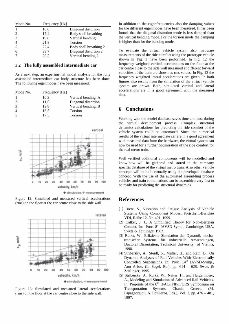
Figure 12: Simulated and measured vertical accelerations(rms) on the floor at the car centre close to the side wall.
Figure 13: Simulated and measured lateral accelerations(rms) on the floor at the car centre close to the side wall.
In addition to the eigenfrequencies also the damping valuesfor the different eigenmodes have been measured. It has beenfound, that the diagonal distortion mode is less damped thanthe vertical bending mode. For the torsion mode the dampingis higher than for the bending mode.
To evaluate the virtual vehicle system also hardwaremeasurements of the ride comfort using the prototype vehicleshown in Fig. 1 have been performed. In Fig. 12 thefrequency weighted vertical accelerations on the floor at thecar centre close to the side wall measured at different forwardvelocities of the train are shown as rms values. In Fig. 13 thefrequency weighted lateral accelerations are given. In bothfigures also results from the simulation of the virtual vehiclesystem are drawn. Both, simulated vertical and lateralaccelerations are in a good agreement with the measureddata.
6 Conclusions
Working with the model database saves time and cost duringthe virtual development process. Complex structuraldynamics calculations for predicting the ride comfort of thevehicle system could be automated. Since the numericalresults of the virtual intermediate car are in a good agreementwith measured data from the hardware, the virtual system cannow be used for a further optimisation of the ride comfort forthe real metro train.
Well verified additional components will be modelled andknow-how will be gathered and stored in the companyspecific database of the virtual metro train. Also other vehicleconcepts will be built virtually using the developed databaseconcept. With the use of the automated assembling processvehicles and train combinations can be assembled very fast tobe ready for predicting the structural dynamics.
References
[1] Dietz, S., Vibration and Fatigue Analysis of VehicleSystems Using Component Modes, Fortschritt-BerichteVDI, Reihe 12, Nr. 401, 1999.
[2] Kalker, J. J., A Simplified Theory for Non-HertzianContact. In: Proc. 8th IAVSD-Symp., Cambridge, USA,Swets & Zeitlinger, 1983.
[3] Rulka, W., Effiziente Simulation der Dynamik mecha-tronischer Systeme für industrielle Anwendungen,Doctoral Dissertation, Technical University of Vienna,1998.
[4] Stribersky, A., Steidl, S., Müller, H., and Rath, B., OnDynamic Analyses of Rail Vehicles With ElectronicallyControlled Suspensions. In: Proc. 14th IAVSD-Symp.,Ann Arbor, (L. Segel, Ed.), pp. 614 – 628, Swets &Zeitlinger, 1995.
[5] Stribersky, A., Rulka, W., Netter, H., and Haigermoser,A., Modeling and Simulation of Advanced Rail Vehicles.In: Preprints of the 8th IFAC/IFIP/IFORS Symposium onTransportation Systems, Chania, Greece, (M.Papageorgiou, A. Pouliezos, Eds.), Vol. 2, pp. 476 – 481,1997.


![MSSP modeling and validation of off-road vehicle ride ... · enhancement in vehicle ride vibration isolations and driver/passengers comfort and health [5-7]. However, the documented](https://static.documents.pub/doc/80x56/5ec7819a4a959e2b4d04a98d/mssp-modeling-and-validation-of-off-road-vehicle-ride-enhancement-in-vehicle.jpg)


