Page 1
1
INDIANA DEPARTMENT OF TRANSPORTATION—2012 DESIGN MANUAL
CHAPTER 409
Abutment, Bent, Pier, and
Bearing
NOTE: References to material in 2011 Design Manual have been highlighted in blue throughout
this document.
2012
Page 2
2
TABLE OF CONTENTS
LIST OF FIGURES ........................................................................................................................ 5
409-1.0 LIMIT STATES, RESISTANCE FACTORS, AND LOADS ......................................... 7
409-1.01 Limit States ................................................................................................................. 7
409-1.01(01) Service-Limit State .......................................................................................... 7
409-1.01(02) Strength-Limit State ......................................................................................... 7
409-1.01(03) Extreme-Event-Limit State .............................................................................. 8
409-1.02 Resistance Factors ...................................................................................................... 8
409-1.03 Load Combinations and Load Factors ........................................................................ 8
409-2.0 INTEGRAL ABUTMENT [Rev. Oct. 2012] .................................................................. 8
409-2.01 General [Rev. Oct. 2012] ........................................................................................... 8
409-2.02 Materials ..................................................................................................................... 9
409-2.03 Design Criteria ............................................................................................................ 9
409-2.03(01) Ends .................................................................................................................. 9
409-2.03(02) Passive Earth Pressure [Rev. Oct. 2012] ............................................................ 9
409-2.03(03) Interior Pile Bent ............................................................................................ 10
409-2.03(04) Shear and Moment ......................................................................................... 10
409-2.04 Design Requirements ................................................................................................ 10
409-2.04(01) General Requirements [Rev. Oct. 2012] ........................................................... 10
409-2.04(02) Pile Connection and Plans Details [Rev. Oct. 2012] .................................... 11
409-3.0 SEMI-INTEGRAL END BENT ..................................................................................... 13
409-3.01 General ..................................................................................................................... 13
409-3.02 Materials ................................................................................................................... 13
409-3.03 Details ....................................................................................................................... 13
409-4.0 PILES, DESIGN CONSIDERATIONS, AND DETAILS FOR END BENTS ............. 13
409-4.01 Piles .......................................................................................................................... 13
409-4.01(01) Pile Spacing ................................................................................................... 14
409-4.01(02) Number of Piles ............................................................................................. 14
409-4.01(03) Cap Overhang ................................................................................................ 14
409-4.01(04) Pile Overload.................................................................................................. 14
409-4.01(05) Live-Load Distribution .................................................................................. 14
409-4.02 Design Considerations .............................................................................................. 15
409-4.02(01) Integral End Bent ........................................................................................... 15
409-4.02(02) Semi-Integral End Bent .................................................................................. 16
409-4.02(03) Wingwalls ...................................................................................................... 16
409-4.03 Details ....................................................................................................................... 17
409-4.03(01) Construction Joint [Rev. Oct. 2012] ............................................................. 17
409-4.03(02) Longitudinal Open Joint................................................................................. 17
2012
Page 3
3
409-5.0 CANTILEVER ABUTMENT AND WINGWALLS..................................................... 17
409-5.01 General [Rev. Oct. 2012] .......................................................................................... 17
409-5.02 Materials ................................................................................................................... 18
409-5.03 Design Considerations .............................................................................................. 18
409-5.03(01) Integral Abutment .......................................................................................... 18
409-5.03(02) Expansion Joints ............................................................................................ 18
409-5.03(03) Abutment-Wingwall Junction ........................................................................ 18
409-5.03(04) Stem Batter ..................................................................................................... 19
409-5.03(05) Concrete Cover .............................................................................................. 19
409-5.03(06) Keyway .......................................................................................................... 19
409-5.03(07) Backfill ........................................................................................................... 19
409-5.03(08) Toe ................................................................................................................. 19
409-5.03(09) Soil Weight .................................................................................................... 20
409-5.03(10) Minimum Footing Thickness ......................................................................... 20
409-5.03(11) Piles ................................................................................................................ 20
409-5.03(12) Loads .............................................................................................................. 20
409-5.03(13) Details ............................................................................................................ 20
409-5.03(14) Drainage ......................................................................................................... 21
409-5.03(15) Construction Joints ......................................................................................... 21
409-6.0 INTERIOR SUPPORTS ................................................................................................. 22
409-6.01 General ..................................................................................................................... 22
409-6.01(01) Types of Interior Supports ............................................................................. 22
409-6.01(02) Usage .............................................................................................................. 22
409-6.02 Materials ................................................................................................................... 23
409-6.02(01) Epoxy-Coated Reinforcement Under Expansion Joint .................................. 23
409-6.02(02) Concrete ......................................................................................................... 23
409-6.03 General Design Considerations ................................................................................ 23
409-6.03(01) Pier in Waterway ............................................................................................ 23
409-6.03(02) Roadway-Grade Separation [Rev. Oct. 2012] .............................................. 24
409-6.03(03) Railroad-Grade Separation [Rev. Oct. 2012] ................................................ 24
409-6.03(04) Pier-Cap Reinforcement ................................................................................. 24
409-6.03(05) Column Reinforcement .................................................................................. 24
409-6.03(06) Reinforcing-Steel Splicing ............................................................................. 24
409-6.03(07) Compression Reinforcement .......................................................................... 24
409-6.03(08) Piles ................................................................................................................ 25
409-6.04 Specific Design Considerations ................................................................................ 25
409-6.04(01) Extended-Pile Bent ........................................................................................ 25
409-6.04(02) Hammerhead Pier ........................................................................................... 26
409-6.04(03) Frame Bent ..................................................................................................... 26
409-6.04(04) Compression .................................................................................................. 27
409-6.05 Details ....................................................................................................................... 27
2012
Page 4
4
409-6.05(01) Size ................................................................................................................. 27 409-6.05(02) Cap Extension ................................................................................................ 27 409-6.05(03) Step Cap ......................................................................................................... 27 409-6.05(04) Construction Joints ......................................................................................... 27 409-6.05(05) Reinforcement Clearance ............................................................................... 28 409-6.05(06) Backfill ........................................................................................................... 28
409-7.0 BEARINGS .................................................................................................................... 28 409-7.01 General ..................................................................................................................... 28
409-7.01(01) Movement ...................................................................................................... 28 409-7.01(02) Effect of Bridge Skew and Horizontal Curvature .......................................... 28 409-7.01(03) Thermal Effects .............................................................................................. 29 409-7.01(04) Loads and Restraint ........................................................................................ 29 409-7.01(05) Serviceability, Maintenance, and Protection Requirements .......................... 29 409-7.01(06) Clear Distance ................................................................................................ 30 409-7.01(07) Bearing Selection ........................................................................................... 30 409-7.01(08) Anchor Plates and Anchor Bolts .................................................................... 31
409-7.02 Elastomeric Bearing Pads and Steel-Reinforced Elastomeric Bearings ................... 31 409-7.02(01) Elastomer ....................................................................................................... 31 409-7.02(02) Steel-Reinforced Elastomeric Bearing Pad .................................................... 32 409-7.02(03) Elastomeric Bearing Pad ................................................................................ 32
409-7.03 Standardized Elastomeric Bearing Pads and Assemblies ......................................... 32 409-7.03(01) Standard Pad and Assembly Types ................................................................ 32 409-7.03(02) Design Parameters.......................................................................................... 33 409-7.03(03) Determining Standard Bearing-Device Type [Rev. Oct. 2012] .................... 33
409-7.04 Nonstandardized Elastomeric Bearing Device ......................................................... 34 409-7.05 Connections for Elastomeric Bearing or PTFE Bearing .......................................... 35 409-7.06 Shear Keys at Semi-Fixed Support ........................................................................... 35 409-7.07 Fixed Steel Bearing .................................................................................................. 36 409-7.08 Pot Bearing ............................................................................................................... 37 409-7.09 Miscellaneous Bearing-Connection Details ............................................................ 37
409-8.0 BRIDGE-SEAT ELEVATIONS .................................................................................... 37
409-9.0 REFERENCES [Rev. Oct. 2012] ................................................................................... 38
FIGURES ...................................................................................................................................... 39
2012
Page 5
5
LIST OF FIGURES
Figure Title
409-2A Use of Integral Abutment [Rev. Oct. 2012]
409-2B Intermediate Pier Detail for Integral Structure Located in Seismic Area with Seismic
Design Category Greater than A [Added Oct. 2012]
409-2C Suggested Integral Abutment Details, Method A, Beams Attached Directly to Piling
[Rev. Oct. 2012]
409-2D Suggested Integral Abutment Details, Method B, Beams Attached to Concrete Cap
[Rev. Oct. 2012]
409-2E Spiral Reinforcement [Added Oct. 2012]
409-2F Tooth Joint [Added Oct. 2012]
409-2G Integral Abutment Placed Behind MSE Wall [Added Oct. 2012]
409-3A Suggested Semi-Integral End Bent Details, Method 1
409-3B Suggested Semi-Integral End Bent Details, Method 2
409-3C Joint Membrane Detail
409-3D Pavement Ledge Detail (for Integral and Semi Integral End Bent)
409-5A Typical Wingwall Details
409-5B Flared-Wing Lengths and End Elevations, Square Structure
409-5C Flared-Wing Lengths and End Elevations, Structure Skewed to Right
409-5D Flared-Wing Lengths and End Elevations, Structure Skewed to Left
409-5E Flared-Wing Corner Dimensions, Square Structure
409-5F Flared-Wing Corner Dimensions, Structure Skewed to Right
409-5G Flared-Wing Corner Dimensions, Structure Skewed to Left
409-5H Typical Abutment Details
409-6A Extended Pile Bent
409-6B Wall Pier on Single Row of Piles
409-6C Hammerhead Pier
409-6D Geometrics for Frame Bent with Solid Stub Wall
409-6E Geometrics for Frame Bent with Individual Crashwalls
409-6F Step Cap
409-6G Suggested Reinforcing Details for Wall or Hammerhead Pier
409-7A Summary of Expansion Bearing Capabilities
409-7B Elastomeric Bearing Pad Types, Properties, and Allowable Values for AASHTO I-
409-7C Elastomeric Bearing Pad Types, Properties, and Allowable Values for Box Beams
409-7D Elastomeric Bearing Pad Types, Properties, and Allowable Values for Indiana Bulb-
Tee Members and Wide Bulb-Tee Members
409-7E Elastomeric Bearing Assembly Types, Properties, and Allowable Values for
Structural-Steel Members
409-7F Elastomeric Bearing Pad with Beveled Steel Plate
2012
Page 6
6
409-7G Nominal Shear Resistance of Anchor Bolts and Pintles
409-7H Minimum Connections for Fixed Steel Shoes
409-7 I Fixed Shoe Assembly
409-7J Elastomeric Bearing Assembly
409-7K Elastomeric Bearing Assembly
409-7L Elastomeric Bearing Assembly with Bottom Plate
409-7M PTFE Elastomeric Bearing Assembly
2012
Page 7
7
CHAPTER 409
ABUTMENTS, BENTS, PIERS,
AND BEARINGS
References shown following section titles are to the AASHTO LRFD Bridge Design
Specifications.
LRFD Section 11 discusses the design requirements for bents, piers, and abutments. Section 14
discusses the design requirements for bearings. This Chapter describes supplementary
information on the design of these structural components. See Chapter 402 for more information
on substructure types and their selection.
409-1.0 LIMIT STATES, RESISTANCE FACTORS, AND LOADS
409-1.01 Limit States
The design of abutments, bents, piers, and bearings shall be in accordance with LRFD.
409-1.01(01) Service-Limit State
Abutment, bents, and piers shall be investigated for excessive vertical and lateral displacement,
and overall stability, at the service-limit state.
LRFD 10.6.2.2, 10.7.2.2, and 10.8.2.2 apply to the investigation of vertical movements.
409-1.01(02) Strength-Limit State
Abutments, bents, and piers shall be investigated at the strength-limit state using LRFD Equation
1.3.2.1-1 for bearing resistance failure, lateral sliding or excessive loss of base contact, pullout
failure of anchors or soil reinforcements, or structural failure.
2012
Page 8
8
409-1.01(03) Extreme-Event-Limit State
Substructure elements for seismic loading shall be designed in accordance with AASHTO Guide
Specifications for LRFD Seismic Bridge Design. For all other extreme events, substructure
elements shall be designed in accordance with AASHTO LRFD Bridge Design Specifications.
409-1.02 Resistance Factors
For abutments, bents, and piers, see LRFD 11.5.6. The resistance factor for bearings shall be
taken as 1.0.
409-1.03 Load Combinations and Load Factors
See LRFD 3.4.1 and 11.5.5.
409-2.0 INTEGRAL ABUTMENT [REV. OCT. 2012]
409-2.01 General [Rev. Oct. 2012]
An integral abutment eliminates the expansion joint in the bridge deck, which reduces both the
initial construction costs and subsequent maintenance costs.
Integral abutments shall be used for a new structure in accordance with the geometric limitations
provided in Figure 409-2A. Minimum support-length requirements need not to be investigated
for an integral-abutments bridge. An integral structure of length of 500 ft or less will not require
seismic analysis, provided the abutment is detailed in accordance with the information provided
in this chapter. An integral structure of 500 ft or longer located in an area in a seismic design
category greater than A will be analyzed using elastic dynamic analysis.
For additional information and research supporting INDOT’s integral abutment design
philosophy, see the following publications:
1. Frosch, R.J., V. Chovichien, K. Durbin, and D. Fedroff. Jointless and Smoother Bridges:
Behavior and Design of Piles. Publication FHWA/IN/JTRP-2004/24. Joint
Transportation Research Program, Indiana Department of Transportation and Purdue
University, West Lafayette, Indiana, 2006. This study investigates the fundamental
2012
Page 9
9
principals affecting the integral abutment, gives recommendations concerning minimum
pile depths, and recommends the limits of use be extended to 500 feet.
2. Frosch, R.J., Kreger, M.E., and A.M. Talbott. Earthquake Resistance of Integral
Abutment Bridges. Publication FHWA/IN/JTRP-2008/11. Joint Transportation Research
Program, Indiana Department of Transportation and Purdue University, West Lafayette,
Indiana, 2009. This study investigates the seismic resistance of the integral abutment.
3. Frosch, R.J. and M.D. Lovell. Long-Term Behavior of Integral Abutment Bridges. Joint
Transportation Research Program, Indiana Department of Transportation and Purdue
University, West Lafayette, Indiana, 2011. This study extends the previous two studies to
further investigate skew and detailing of the integral abutment.
409-2.02 Materials
Class C concrete and epoxy-coated reinforcing steel are required.
The wingwalls concrete shall be Class C.
409-2.03 Design Criteria
Although each end of the superstructure is monolithically attached to an integral end bent, the
rotation permitted by the piles is sufficiently high, and the attendant end moment is sufficiently
low, to justify the assumption of a pinned-end condition for design. The following design
assumptions shall be considered.
409-2.03(01) Ends
The ends of the superstructure are free to rotate and translate longitudinally.
409-2.03(02) Passive Earth Pressure [Rev. Oct. 2012]
The restraining effect of passive earth pressure behind the abutments may be neglected in
considering superstructure longitudinal force distribution to the interior piers. Alternatively, the
effect of passive earth pressure behind the abutments may be considered by distributing the
longitudinal forces between the interior supports, abutment supports, and the soil behind the
abutments.
2012
Page 10
10
409-2.03(03) Interior Pile Bent
All longitudinal forces from the superstructure shall be distributed among the interior supports,
end bents, and soil behind the end bents based on relative stiffness in designing an interior pile
bent or a thin-wall pier on a single row of piles.
409-2.03(04) Shear and Moment
Force effects in the cap beam may be determined on the basis of a linear distribution of vertical
pile reactions. For minimum reinforcement, the cap shall be treated as a structural beam.
409-2.04 Design Requirements
409-2.04(01) General Requirements [Rev. Oct. 2012]
The following requirements must be satisfied.
1. Backfill. Each integral end bent for a beam- or girder-type superstructure shall be
backfilled with aggregate for end-bent backfill. Each reinforced-concrete-slab bridge end
bent shall be backfilled with flowable-backfill material. The INDOT Standard Drawings
provide backfill details for both concrete-slab and beam- or girder-type structures.
2. Bridge Approach. A reinforced-concrete bridge approach, anchored to the abutment with
#5 bars, epoxy coated, and spaced at 1’-0” centers, shall be used at each integral
abutment regardless of the traffic volume. The bars shall extend out of the pavement
ledge as shown in Figures 409-2C and 409-2D. Two layers of polyethylene sheeting
shall be placed between the reinforced-concrete bridge approach and the subgrade. A
rigid reinforced-concrete bridge approach is necessary to prevent compaction of the
backfill behind the abutment.
3. Bridge-Approach Joint. For a structure of length of less than 300 ft, a terminal joint of 2
ft width, as shown on the INDOT Standard Drawings, or a pavement-relief joint, should
be placed at the end of the reinforced-concrete bridge approach. An expansion joint
should be considered for an integral structure having length from 300 ft to 500 ft. An
expansion joint is required for an integral structure of length greater than 500 ft, as shown
in Figure 409-2F.
2012
Page 11
11
4. Wingwalls Configuration. Wingwalls shall extend parallel to the centerline of roadway.
This configuration reduces the loads imposed upon the bridge structure due to passive
earth pressure from the end-bent backfill. See Figure 409-5A for suggested wingwall
dimensioning details. The minimum thickness of a wingwall used with an integral end
bent shall be 1 ft. The wingwall length shall not be greater than 10 ft. A longer wingwall
will require additional analysis.
5. Wingwall Connection. Force effects in the connection between the wingwall and cap,
and in the wingwall itself, shall be investigated, and adequate reinforcing steel shall be
provided.
6. Interior Diaphragms for Steel Structure. Where steel beams or girders are used, an
interior diaphragm shall be placed within 10 ft of the end support to provide beam
stability prior to and during the deck pour.
7. Intermediate Pier Details for Integral Structure Located in Seismic Area with Seismic
Design Category Greater than A. Intermediate piers should include concrete restrainers
as shown in Figure 409-2B.
409-2.04(02) Pile Connection and Plans Details [Rev. Oct. 2012]
An integral abutment may be constructed using either of the methods as follows (see Figures
409-2C and 409-2D).
1. Method A. The superstructure beams are placed on and attached directly to the abutment
piling. The entire abutment is then poured at the same time as the superstructure deck.
This is the preferred method.
2. Method B. The superstructure beams are set in place and anchored to the previously cast-
in-place abutment cap. The concrete above the previously cast-in-place cap shall be
poured at the same time as the superstructure deck.
Optional construction joints may be placed in the abutment cap to facilitate construction. An
optional joint below the bottom of the beam may be used regardless of bridge length. The
optional construction joint at the pavement-ledge elevation shown in Figures 409-2C and 409-2D
allows the contractor to pour the reinforced-concrete bridge approach with the bridge deck.
Regardless of the method used, the abutment shall be in accordance with the following.
1. Width. The width shall not be less than 2.5 ft.
2012
Page 12
12
2. Cap Embedment. The embedment of the piles into the cap shall be 2 ft. The embedded
portion of the pile should be confined with spiral reinforcement as shown in Figure 409-
2E.
3. Beam Attachment. The beams shall be physically attached to the piling if using Method
A, or to the cast-in-place cap if using Method B.
4. Beam Extension. The beams shall extend at least 1.75 ft into the bent, as measured along
the centerline of the beam.
5. Concrete Cover. Concrete cover beyond the farthest-most edge of the beam at the rear
face of the bent shall be at least 4 in. This minimum cover shall also apply to the
pavement-ledge area. The top flanges of structural-steel or prestressed-concrete I-beams
may be coped to satisfy this requirement. Where the 4-in. minimum cover cannot be
maintained within a 2.5-ft cap, the cap shall be widened.
6. Stiffener Plates. Structural-steel members shall have stiffener plates welded to both sides
of their webs and to the flanges over the supports to anchor the beams into the concrete.
7. Reinforcement Through the Webs of Beams. A minimum of three holes shall be
provided through the webs of steel members near the front face of the bent for #6 bars to
be inserted through. Two holes shall be provided through prestressed-concrete I-beam
webs near the front face of the bent, to allow #6 bars to be inserted to further anchor the
beam to the cap. Box beams shall have two threaded inserts placed in each side face for
anchorage of #7 threaded bars.
8. End-Bent Reinforcement. The minimum size of stirrups shall be #6 spaced at a
maximum of 1’-0”. Longitudinal cap reinforcement shall be at least #7 at 1’-0”
maximum spacing along both faces of the bent. All reinforcing steel shall be epoxy
coated.
9. Corner Bars. Corner bars shall extend from the rear face of the cap into the top of the
deck at not more than 1’-0” spacing as shown in Figures 409-2B and 409-2C. The
figures show suggested details for an integral end bent with a structural-members bridge.
Other reinforcement and connection details shall be used where they are structurally
sound and afford an advantage if compared to that shown in the figures. See Figures 409-
2B and 409-2C for drainage-pipes placement behind an end bent. See LRFD 11.4.1 and
11.6.6 for additional drainage information.
2012
Page 13
13
10. If placed behind an MSE retaining wall, the abutment should be configured as shown in
Figure 409-2G.
409-3.0 SEMI-INTEGRAL END BENT
409-3.01 General
Semi-integral end bents shall be considered if integral end bents are not practical or feasible. For
a skew angle of greater than 30 deg or an expansion length of 250 ft or longer, twisting or
racking of the bridge shall be investigated.
Minimum support-length requirements shall be investigated for semi-integral end bent Method 2.
409-3.02 Materials
Semi-integral end bents and wingwalls will require the use of class C concrete and epoxy-coated
reinforcing steel.
409-3.03 Details
Figure 409-3A shows details for Method 1. Figure 409-3B shows details for Method 2. Figure
409-3C shows details for the joint-protection sheeting. Figure 409-3D shows details pavement-
ledge details for integral and semi-integral end bents. All applicable information shown in the
figures shall be shown on the plans.
Wingwalls details are similar to those for an integral end bent except for the connection method.
The wingwall is connected to the bent below the seat elevation. See Figure 409-5A for
suggested wingwall-dimensioning details. The minimum wingwall thickness of a wingwall shall
be 1 ft.
See LRFD 11.4.1 and 11.6.6 for additional drainage information.
409-4.0 PILES, DESIGN CONSIDERATIONS, AND DETAILS FOR END BENTS
409-4.01 Piles
The following criteria apply to piling for an integral, semi-integral, or non-integral end bent.
2012
Page 14
14
409-4.01(01) Pile Spacing
Pile spacing shall not exceed 10 ft. If the cap is properly analyzed and designed as a continuous
beam, this restriction need not apply. If practical, one pile may be placed beneath each girder.
See Chapter 408 for minimum pile spacing. For an integral end bent within the limits defined in
Figure 409-2A, or for a non-integral end bent, the piles are considered to be free-ended and
capable of resisting only horizontal and vertical forces.
409-4.01(02) Number of Piles
See Chapter 408 for the minimum number of piles.
409-4.01(03) Cap Overhang
The minimum cap overhang shall be 1.5 ft measured from centerline of pile.
409-4.01(04) Pile Overload
If an individual pile is overloaded due to the maximum beam or girder loads, the overload
amount may be considered equally distributed to the two adjacent piles provided that this
distribution of overloads does not cause either of the adjacent piles to exceed its allowable
bearing capacity. This distribution of overload will be permitted only if the allowable bearing
value for the pile is based upon the capacity of the soils and not on the structural strength of the
pile, and if the pile cap has enough beam strength to distribute the overload to the adjacent piles.
409-4.01(05) Live-Load Distribution
The wheel loads located out in the span shall be distributed to the substructure in accordance
with the live-load distribution factors shown in LRFD 4.6.2.2.2. For wheels located over the
support, a simple-span transverse distribution shall be used.
2012
Page 15
15
409-4.02 Design Considerations
409-4.02(01) Integral End Bent
The following criteria apply specifically to piles and loads.
1. Loads and Forces. Only vertical loads shall be considered in designing end-bent piling
for a structure which satisfies the requirements provided in Figure 409-2A. Force effects
in the end-bent piles due to temperature, shrinkage, and creep may be neglected.
An alternative analysis shall be used if the criteria in Figure 409-2A are not satisfied.
The analysis to be made is as follows.
a. The point of zero movement shall be established by considering the elastic
resistance of all substructure elements, bearing devices, and passive earth
pressure.
b. The effects of creep, shrinkage, and temperature shall be considered.
c. Movement at a point on the superstructure shall be taken as being proportional to
its distance to the point of zero movement.
d. Lateral curvature of the superstructure may be neglected if it satisfies LRFD
4.6.1.2.
e. Vertical force effects in the end-bent piles shall be distributed linearly with load
eccentricities properly accounted for.
f. Lateral soil resistance shall be considered in establishing force effects and
buckling resistance of piles.
Force effects shall be combined in accordance with LRFD 3.4.1.
2. Pile Type. Only steel H-piles or pipe piles shall be used with an integral end bent. Steel
H-pile webs shall be placed perpendicular to the centerline of the structure to minimize
flexural forces in the piling. All end bent piling shall be driven vertically. Only one row
of piling is permitted.
2012
Page 16
16
409-4.02(02) Semi-Integral End Bent
1. Pile Spacing. The minimum pile spacing shall be as specified in Chapter 408. For a
structure with deep girders, two rows of piles with staggered pile spacing shall be
considered.
2. Batter. Up to one-half of the piles may be battered to increase the resistance to horizontal
movement of the structure.
3. Overturning. If the pile spacing is less than 10 ft and one-half of the piles are battered,
overturning need not be investigated. If less than one-half of the piles are battered, or if
the pile spacing is 10 ft or greater, the stability due to overturning pressures shall be
investigated.
409-4.02(03) Wingwalls
With respect to a spill-through end bent, the following applies to wingwalls.
1. Usage. Each structural-steel or prestressed-concrete beam bridge requires wingwalls. A
reinforced-concrete slab bridge usually does not require wingwalls.
2. Dimensions. Wingwalls shall be of sufficient length and depth to prevent the roadway
embankment from encroaching onto the stream channel or clear opening. The slope of
the fill shall not be steeper than 2:1, perpendicular to the skew. Wingwall lengths can be
established on this basis. For more information, see LRFD 11.6.1.4 for more
information. See Figure 409-5A for suggested wingwall-dimensioning details. The
minimum thickness of a wingwall used with an end bent shall be 1 ft.
3. Pile Support. If the wingwalls for a non-integral or semi-integral end bent have a total
length of more than 10 ft, pile support shall be investigated. Pile-supported wings shall
not be used with an integral end bent.
4. Design. A non-pile-supported wingwall shall be designed as a horizontal cantilevered
wall. Because the wingwalls are rigidly attached to the remainder of the bent, the bent is
restrained from deflecting except laterally as a unit. Due to the lack of the usual
retaining-structure rotation, the active-soil-pressure condition cannot develop, and the
design soil pressure must be increased to a value between the active and at-rest condition.
Therefore, the horizontal earth pressure to be used in design shall be equal to 150% of the
2012
Page 17
17
value determined assuming an active-soil condition. Live-load surcharge shall be added
to the soil loads in accordance with LRFD3.11.6.2.
409-4.03 Details
409-4.03(01) Construction Joint [Rev. Oct. 2012]
The following applies to a construction joint at a spill-through end bent.
1. Type. Construction joint type A shall be used for each horizontal construction joint. See
the INDOT Standard Drawings.
2. Integral. See Figures 409-2C and 409-2D for construction-joint use at an integral
abutment.
409-4.03(02) Longitudinal Open Joint
If the bridge deck includes a longitudinal open joint, an expansion joint shall also be placed in
the end bent. Also, flashing shall be placed behind the joint in the end bent. See the INDOT
Standard Drawings.
409-5.0 CANTILEVER ABUTMENT AND WINGWALLS
409-5.01 General [Rev. Oct. 2012]
See Chapter 402 and LRFD 11.6 for more information on the selection and design of abutments.
An abutment functions as both an earth-retaining and vertical-load-carrying structure. A parapet
abutment is designed to accommodate thermal movements with strip-seal expansion devices
between the concrete deck and abutment end block. An integral abutment shall be designed to
accommodate movements at the roadway end of the approach panel.
A mechanically-stabilized-earth-wall bridge abutment placed adjacent to a roadway need not to
be checked for vehicle-collision forces as described in LRFD 3.6.5. However, if the wall must
be placed inside the clear zone, roadside safety shall be addressed.
A mechanically-stabilized-earth-wall bridge abutment placed adjacent to a railroad track shall be
in accordance with Section 409-6.03(03).
2012
Page 18
18
For soil conditions or bridge geometric dimensions not suitable for a spill-through end bent or
mechanically-stabilized-earth abutment, an abutment with wingwalls of the cantilever type shall
be used. Such a cantilever structural unit shall be founded on a spread footing, drilled shafts, or
a driven-pile footing with a minimum of two rows of piles. The front row of piles may be
battered a maximum of 1:4 to provide additional horizontal resistance.
409-5.02 Materials
For a mechanically-stabilized-earth abutment, the required materials are described in the INDOT
Standard Specifications.
For an abutment or wingwall, class A concrete shall be used for all components above the
footing. Class B concrete shall be used in the footing.
If an expansion joint is located directly over the abutment cap, all reinforcement in the abutment
wall shall be epoxy coated.
409-5.03 Design Considerations
409-5.03(01) Integral Abutment
An integral abutment shall be designed to resist and absorb creep, shrinkage, and thermal
deformations of the superstructure. Movement calculations shall consider temperature, creep,
and long-term prestress shortening in determining potential movements. See LRFD 11.6.1.3 for
more information.
409-5.03(02) Expansion Joints
Vertical expansion joints shall be considered for an abutment whose width exceeds 90 ft, as
indicated in LRFD 11.6.1.6.
409-5.03(03) Abutment-Wingwall Junction
The junction of the abutment wall and wingwall is a critical design element, requiring the
considerations as follows.
2012
Page 19
19
1. If the abutment wall and wingwall are designed using active earth pressure, the two
elements shall be separated by a filled expansion joint of ½-in. width to permit the
expected deformations. If the abutment is designed using at-rest earth pressure, an
expansion joint between the wingwall and abutment wall is not required.
2. If the wingwall is tied to the abutment wall with no joint, all horizontal steel
reinforcement shall be developed into both elements such that full moment resistance can
be obtained.
409-5.03(04) Stem Batter
Where a batter is used, it shall range from 1:10 through 1:15.
409-5.03(05) Concrete Cover
See LRFD Table 5.12.3-1 for more information.
409-5.03(06) Keyway
A keyway shall be used in each vertical expansion joints. See the INDOT Standard Drawings
for details.
409-5.03(07) Backfill
The abutment and wingwalls shall be backfilled with structure backfill. The neat-line limits shall
be shown on the Layout sheet.
409-5.03(08) Toe
The fill on the toe of footing shall be ignored in investigating sliding resistance.
2012
Page 20
20
409-5.03(09) Soil Weight
Only the weight of the soil which is vertically above the heel of the footing shall be included in
the overturning-stability analysis and the structural design of the footing.
409-5.03(10) Minimum Footing Thickness
The minimum thickness shall be 1.5 ft.
409-5.03(11) Piles
A footing on piles shall be analyzed to consider the structural contribution of the concrete below
the tops of the piles. Bottom-mat reinforcement shall be placed 4 in. above the bottom of the
footing.
The pile type shall be based on the recommendations provided in the geotechnical report. Pile
spacing shall be as described in Chapter 408. Pile embedment into the footing shall be at least
1.5 ft.
409-5.03(12) Loads
An abutment stem shall be designed for the imposed gravitational loads, weight of the stem, and
horizontal loads. The static earth pressure shall be determined in accordance with LRFD 3.11
and 11.6.1.2. Passive earth pressure shall not be assumed to be generated by the prism of earth
in front of the wall.
409-5.03(13) Details
Figure 409-5A shows typical wingwall details for integral, semi-integral, or non-integral end
bents. Figure 409-5E illustrates the preferred methods for determining the geometrics for a
flared wingwall for a square structure. Figures 409-5C and 409-5F illustrate this for a structure
skewed to the right. Figures 409-5D and 409-5G illustrate this for a structure skewed to the left.
Figure 409-5B provides an example for determining a flared-wing length and elevations.
Figure 409-5H provides suggested typical abutment details.
2012
Page 21
21
409-5.03(14) Drainage
Positive drainage shall be provided behind each abutment or wingwall. See the INDOT
Standard Drawings for a weephole detail. See LRFD 11.6.6 for more information. Drains shall
be located in an abutment or wingwall as follows.
1. Abutment with Wingwalls of 15 ft or Shorter. Drains shall be spaced at 12 ft maximum
in the abutment. Drains shall be omitted from the wingwalls.
2. Abutment with Wingwalls of Longer Than 15 ft. Drains shall be spaced at 12 ft
maximum in the abutment, with a 12-ft maximum distance from the ends of the
wingwalls.
3. Location of Drain Outlet. The outlet shall be placed 1 ft above the low-water elevation or
the proposed ground-line elevation.
409-5.03(15) Construction Joints
A construction joint type A shall be used for all horizontal construction joints in both the
abutment and wingwalls. See the INDOT Standard Drawings. Vertical construction joints shall
be placed as follows.
1. Abutment. Preferably at 30 ft center to center, with a maximum of 40 ft.
2. Wingwall of 20 ft or Longer. At 20 ft center-to-center and one batter face cut.
3. Wingwall Shorter than 20 ft. In the abutment section so that the combined length of
wingwall and abutment between joints is approximately 20 ft.
4. Either the Wingwall or the Abutment. Not less than 1.5 ft from the intersection of batter
faces at the top of the footing.
Joints shall not be placed under bridge bearing areas.
The horizontal reinforcing steel shall continue through the construction joint. Vertical bars shall
be placed at a minimum of 3 in. from the centerline of the joint.
2012
Page 22
22
409-6.0 INTERIOR SUPPORTS
409-6.01 General
409-6.01(01) Types of Interior Supports
1. Extended-Pile or Drilled-Shaft Bent. The economy of a substructure can be enhanced
under certain conditions by means of extending a deep foundation, such as a single row
of driven piles or drilled shafts above ground level to the superstructure. An extended-
pile bent may be of the integral type or the non-integral type. See Figure 409-6A for
details.
2. Stem-Type Pier. The types of stem piers are as follows.
a. Single-Wall. This is a relatively thin wall, set on a single row of piles, a spread
footing, or a pile cap with multiple rows of piles. The single-wall is most suitable
if its structural height is less than 20 ft. See Figure 409-6B for a wall pier on a
single row of piles.
b. Hammerhead. For a larger structural height or pier width, a hammerhead pier,
either with a rectangular or rounded stem, is often more suitable. See Figure 409-
6C for a hammerhead pier.
3. Frame Bent. A concrete frame bent may be used to support a variety of superstructures.
The columns may be either circular or rectangular in cross section. The columns may be
directly supported by the footing or by a partial-height wall. Figures 409-6D and 409-6E
illustrate a frame bent. If the columns rest directly on the footing, the footing shall be
designed as a two-way slab. Construction joints may be required in the cap if the
concrete-shrinkage moment introduced into the columns becomes excessive.
409-6.01(02) Usage
The selection of the interior-support type shall be based on the feature passing beneath the
bridge, as follows.
1. Major Water Crossing. A hammerhead, wall, or single round column-type pier supported
by a deep foundation or a spread footing on rock is preferred. Multiple round columns
may be used, but they may require a solid wall between columns to avoid the collection
2012
Page 23
23
of debris. This decision shall be coordinated with the Office of Hydraulics. A single-
wall pier may be a more suitable alternative.
2. Meandering River. For a meandering river or stream, or where the high flow is at a
different skew than the low flow, the most desirable pier type is normally a single,
circular pier column.
3. Highway- or Railroad-Grade Separation. A thin-wall or frame bent with multiple
columns shall be used. The aesthetics of the pier shall be considered. Solid wall piers
under a wide superstructure can lead to a tunnel effect for a motorist passing under the
structure, and may require the placement of a lighting system under the structure.
Surface treatments using form liners or other means shall be investigated, especially for a
wall pier.
409-6.02 Materials
409-6.02(01) Epoxy-Coated Reinforcement Under Expansion Joint
All reinforcing steel in the concrete above the footing, where an expansion joint is located
directly over the cap shall be epoxy coated. This includes the stem, cantilevers, and cap. This
applies only to a substructure which supports the ends of two superstructure units with an
expansion joint located directly over the cap.
409-6.02(02) Concrete
Class A concrete shall be used above the footing. Class B concrete shall be used in the footing.
409-6.03 General Design Considerations
409-6.03(01) Pier in Waterway
A stem-type pier shall have a solid wall to an elevation of 1 ft above the Q100 high-water level.
Depending on aesthetics and economics, the remainder of the wall may be either solid or
multiple columns. The dimensions of the wall may be reduced by providing cantilevers to form
a hammerhead pier. Round noses shall be considered for a pier in a waterway.
2012
Page 24
24
409-6.03(02) Roadway-Grade Separation [Rev. Oct. 2012]
A new-bridge pier located within 30 ft of the edge of roadway shall be designed for a vehicular
collision-static force of 600 kip, as indicated in LRFD 3.6.5.1.
409-6.03(03) Railroad-Grade Separation [Rev. Oct. 2012]
A pier within 25 ft of a present-track or a future-track centerline shall be designed in accordance
with the AREMA Manual for Railway Engineering.
409-6.03(04) Pier-Cap Reinforcement
Multiple layers of negative-moment reinforcement are permitted to minimize cap dimensions.
409-6.03(05) Column Reinforcement
The area of steel reinforcement provided across the interface between the base of the column or
pier stem and the top of footing shall not be less than 0.5% of the gross area of column or stem as
described in LRFD 5.13.3.8. According to LRFD 5.10.11.4.2, the minimum reinforcement ratio,
both horizontally and vertically in a pier, shall not be less than 0.0025. The vertical
reinforcement ratio shall not be less than the horizontal reinforcement ratio. The reinforcement
spacing, either horizontally or vertically, shall not exceed 1’-6”.
409-6.03(06) Reinforcing-Steel Splicing
If a pier-stem height is less than 10 ft, the steel extending out of the footing shall not be spliced.
See LRFD 5.11.5 for more information.
409-6.03(07) Compression Reinforcement
Compression steel tends to buckle once the concrete cover is gone or where the concrete around
the steel is weakened by compression. The criteria shown in LRFD 5.7.4.2 and 5.7.4.6 for ties or
spirals shall be used. See Figure 409-6G for suggested hammerhead- and wall-type-pier
reinforcement in columns without plastic hinging capability. Ties may be #3 bars for
longitudinal bars up to size #10.
2012
Page 25
25
Where column and pier-wall reinforcement is controlled by seismic requirements, see the
AASHTO Guide Specifications for LRFD Seismic Bridge Design Articles 8.6 and 8.8 for limits
of reinforcement.
409-6.03(08) Piles
For a pier on multiple rows of piles with a footing, pile embedment shall be at least 1.5 ft inside
the footing. Bottom-mat reinforcement shall be placed 4 in. above the bottom of the footing.
For a pier on a single row of piles, pile embedment inside the wall shall be 5 ft.
409-6.04 Specific Design Considerations
409-6.04(01) Extended-Pile Bent
1. Limitations. This type of support has little resistance to longitudinal forces, particularly
seismic forces, and shall not be used unless such forces are resisted by other substructure
units such as integral end bents or abutments. This support shall also not be used if the
stream carries large debris, heavy ice flow, or large vessels. If steel H-piles are used for
support, they shall be encased in concrete. The concrete encasement shall be extended to
2 ft below the flow-line elevation. Encasement details are provided on the INDOT
Standard Drawings. Scour shall be considered in establishing design pile lengths and for
the structural design of the piles.
2. Cap Beam. Extended piles require a cap beam for structural soundness, which may be an
integral part of the superstructure. Extended drilled shafts shall be arranged to support,
for example, widely-spaced beams without the presence of a cap beam if sufficient space
is provided at the top for mandatory jacking operations.
3. Loads. Girders may be fixed or semi-fixed at an extended pile bent. Because the piles
are relatively flexible compared to the end bent or abutment, the force effects induced in
the piles by lateral displacement is small. Where practical, one pile shall be placed
beneath each girder. The vertical load carried by the piles shall be the girder reaction and
the appropriate portion of the pile-cap dead load. Assuming the bent acts as a rigid frame
in a direction parallel to the bent, force effects due to lateral displacement and lateral
loads may be uniformly distributed among the extended piles.
2012
Page 26
26
4. Cap Design. The minimum reinforcement shall be #5 bars at 1’-0” spacing on all faces,
and shall be in accordance with LRFD 5.7.3.3. The cap shall be designed as a continuous
beam.
409-6.04(02) Hammerhead Pier
1. Cofferdam. If a cofferdam is anticipated to be required, the hammerhead portion of the
pier shall be above the average low-water level of the stream.
2. Bottom Elevation. The bottom of the hammerhead portion shall be a minimum of 6 ft
above the finished ground line at a stream crossing to help prevent debris accumulation.
3. Effective-Length Factor. LRFD Table 4.6.2.5-1 provides criteria for the effective length
factor, K. For beams on rockers or sliding bearings, K shall be taken as 2.1. For an
expansion pier with beams on a single row of neoprene pads, K shall be taken as 1.5. For
prestressed-concrete beams on semi-fixed bearings on a fixed pier, K shall be taken as
1.2. K shall be taken as 1.0 for the strong or transverse direction.
4. Pier Wall. A pier wall shall be designed as columns for biaxial bending. See LRFD
5.7.4.5 for more information.
409-6.04(03) Frame Bent
1. Column Fixity. The columns founded on a spread- or multiple-piles footing shall be
assumed to be fixed at the bottom.
2. Cantilevered Cap. The moments used for the cap design shall be calculated at the face of
the support for a square or rectangular column, or at the theoretical face of a circular
column.
3. Effective-Length Factor. The same K factors shall be taken as described for a
hammerhead pier in Section 409-6.04(02), in the weak, or longitudinal, direction. K shall
be taken as 1.0 for the strong, or transverse, direction. See LRFD 4.6.2.5 for more
information.
4. Structural Design. If the number of columns is kept to a minimum, and the components
are reasonably small, frame analysis is both appropriate and safe for a frame bent.
2012
Page 27
27
409-6.04(04) Compression
Reinforced-concrete piers, pier columns, and piles are referred to as compression members
although their design is normally controlled by flexure. Tall, slender columns or pier shafts are
relatively rare due to topography. The use of the moment magnification approach in LRFD
5.7.4.1 is most-often warranted. For exceptionally tall or slender columns or shafts, a refined
analysis, as outlined in LRFD 5.7.4.1, shall be performed.
For limits of reinforcement in compression members, see LRFD 5.7.4.
409-6.05 Details
409-6.05(01) Size
Columns can be rectangular, square, or round, with a minimum diameter or thickness of 2 ft.
Diameter increments shall be in multiples of 0.5 ft. A solid pier wall shall have a minimum
thickness of 2 ft, and may be widened at the top to accommodate the bridge seat.
409-6.05(02) Cap Extension
The width of the cap shall project beyond the sides of the columns. The added width of the cap
shall be a minimum of 1½ in. on the outside the columns. This width will reduce the
reinforcement interference between the column and cap. The cap shall have cantilevered ends to
balance positive and negative moments in the cap.
409-6.05(03) Step Cap
Where one end of the cap is on a considerably different elevation than the other, the difference
shall be accommodated by means of increasing the column heights as shown in Figure 409-6F.
The bottom of the cap shall be sloped at the same rate as the cross slope of the top of the bridge
deck. The top of the cap shall be stepped to provide level bearing surfaces.
409-6.05(04) Construction Joints
A construction joint type A shall be used for all horizontal construction joints. See the INDOT
Standard Drawings.
2012
Page 28
28
409-6.05(05) Reinforcement Clearance
The reinforcement clearances shall be checked to ensure that there is adequate space for the
proper placement of the concrete during construction.
409-6.05(06) Backfill
An interior bent or pier at the base of a slopewall shall be backfilled with structure backfill as
shown on the INDOT Standard Drawings. For an interior bent or pier adjacent to a railroad
track, the area shall be backfilled with structure backfill to a point 1.5 ft outside the neat lines of
the footing. Structure backfill shall not be provided as backfill material around a pier that is
located in a stream.
409-7.0 BEARINGS
409-7.01 General
Bearings ensure the functionality of a bridge by allowing translation and rotation to occur while
supporting the vertical loads. However, the use of integral abutments and possibly integral piers
shall be considered prior to deciding upon the use of bearings to support the structure.
409-7.01(01) Movement
Movement shall be considered. Movement includes both translations and rotations. The sources
of movement include bridge skew and horizontal-curvature effects, initial camber or curvature,
construction loads, misalignment or construction tolerances, settlement of supports, thermal
effects, creep, shrinkage, or traffic loading. Bearing pads on a skewed structure shall be oriented
parallel to the principal rotation axis.
409-7.01(02) Effect of Bridge Skew and Horizontal Curvature
A skewed bridge moves both longitudinally and transversely. The transverse movement
becomes significant on a bridge with a skew angle of greater than 20 deg and bearings not
oriented parallel to the movement of the structure.
2012
Page 29
29
A curved bridge moves both radially and tangentially. These complex movements are
predominant in a curved bridge with a small radius and with an expansion length of longer than
200 ft.
409-7.01(03) Thermal Effects
Thermal translation, Δo, is estimated as follows:
Δo = αLΔT
where L is the expansion length, α is the coefficient of thermal expansion of 6.0 x 10⁻⁶
/ F for
normal-density concrete, or 6.5 x 10⁻⁶
/ F for steel, and ΔT is the change in the average bridge
temperature from the installation temperature.
A change in the average bridge temperature causes a thermal translation. A change in the
temperature gradient induces bending and deflections. The design temperature changes are
specified in LRFD 3.12. Maximum and minimum bridge temperatures are defined depending
upon whether the location is viewed as a cold or moderate climate. Indiana is considered a cold
climate. See LRFD 3.12 for temperature-range values. An installation temperature of 60 F
shall be assumed. The change in average bridge temperature, ΔT, between the installation
temperature and the design extreme temperature is used to compute the positive and negative
movements. A given temperature change causes thermal movement in all directions. This
means that a short, wide bridge can experience greater transverse movement than longitudinal
movement.
409-7.01(04) Loads and Restraint
Restraint forces occur if part of a movement is prevented. Forces due to direct loads include the
dead load of the bridge and loads due to traffic, earthquakes, water, or wind. Temporary loads
due to construction equipment and staging also occur. The majority of the direct design loads
are reactions of the bridge superstructure on the bearing. Therefore, they can be estimated from
the structural analysis. The applicable LRFD load combinations shall be considered.
409-7.01(05) Serviceability, Maintenance, and Protection Requirements
Bearings under a deck joint collect large amounts of dirt and moisture, which promotes problems
of corrosion and deterioration. As a result, such bearings shall be designed and installed to have
2012
Page 30
30
the maximum possible protection against the environment and to allow easy access for
inspection.
The service demands on bridge bearings are severe and result in a service life that is typically
shorter than that of other bridge elements. Therefore, allowances for bearing replacement shall
be part of the design process. Lifting locations shall be provided to facilitate removal and re-
installation of bearings without damaging the structure. No additional hardware shall be
necessary for this purpose. The primary requirements are to allow space suitable for lifting jacks
based on the original design and to use devices that permit quick removal and replacement of the
bearing.
409-7.01(06) Clear Distance
The minimum clear distance between the bottom shoe of a steel bearing and the edge of the
bearing seat or cap shall be 3 in. For an elastomeric pad resting directly on the concrete bridge
seat, the minimum edge distance shall be 6 in. under a deck expansion joint, or 3 in. with 4 in.
desirable for all other locations. Seismic support lengths shall also be checked.
409-7.01(07) Bearing Selection
Bearing selection is influenced by factors such as loads, geometry, maintenance, available
clearance, displacement, rotation, deflection, availability, policy, designer preference,
construction tolerances, or cost.
Vertical displacements are prevented, rotations are allowed to occur as freely as possible, and
horizontal displacements may be either accommodated or prevented. The loads shall be
distributed among the bearings in accordance with the superstructure analysis.
Unless conditions dictate otherwise, conventional steel-reinforced elastomeric bearings shall be
used for a girder bridge. Where the practical limits of an elastomeric bearing pad are exceeded,
flat polytetrafluorethylene (PTFE) slider plates shall be considered in conjunction with a steel-
reinforced elastomeric bearing. See Figure 409-7A for a general summary of expansion-bearing
capabilities. The values shown in the figure are for guidance only.
The final step in the selection process consists of completing a design of the bearing in
accordance with LRFD 14.7. The resulting design will provide the geometry and other pertinent
specifications for the bearing.
2012
Page 31
31
For a structure widening, bearing types shall not be mismatched. Yielding type bearings, such as
elastomeric, shall not be used in conjunction with steel rockers or other non-yielding type
bearings.
A steel-beam bridge without integral end bents must have at least one fixed bearing line. Due to
the presence of the interior-diaphragm keyway, semi-fixed interior supports are allowed for a
prestressed-concrete beams bridge. If integral end bents in accordance with the empirical design
limits are used, interior fixed bearings are not required.
409-7.01(08) Anchor Plates and Anchor Bolts
Anchor plates shall be used only to attach the bottom steel shoe of an expansion bearing to the
concrete beam seat. Anchor bolts shall be used to connect fixed steel bearings to the concrete
beam seat.
409-7.02 Elastomeric Bearing Pads and Steel-Reinforced Elastomeric Bearings
Elastomers are used in both elastomeric bearing pads and steel-reinforced elastomeric bearings.
The behavior of both pads and bearings is influenced by the shape factor, S, as shown in LRFD
14.7.5.1.
Elastomeric bearing pads and steel-reinforced elastomeric bearings have fundamentally different
behaviors and, therefore, they are discussed separately. Elastomeric pads and bearings shall be
oriented so that the long side is parallel to the principal axis of rotation, as this facilitates the
accommodation of rotation.
Holes shall not be placed in an elastomeric bearing pad due to increased stress concentrations
around the hole. These increased stresses can cause tearing of the elastomer during an extreme
event, such as an earthquake. If holes are placed in a steel-reinforced bearing, the steel-
reinforcement thickness shall be increased in accordance with LRFD 4.7.5.3.7.
409-7.02(01) Elastomer
For details and material properties of elastomeric bearings, see the INDOT Standard Drawings,
and INDOT Standard Specifications, respectively.
2012
Page 32
32
409-7.02(02) Steel-Reinforced Elastomeric Bearing Pad
For design requirements, see LRFD 14.7.6.
409-7.02(03) Elastomeric Bearing Pad
For design requirements for PEP, FGP, and CDP bearing pads, see LRFD 14.7.6.
409-7.03 Standardized Elastomeric Bearing Pads and Assemblies
Standardized elastomeric bearing pads and assemblies have been developed for use with
AASHTO prestressed-concrete I-beams, Indiana prestressed-concrete bulb-tee beams,
prestressed-concrete hybrid bulb-tee beams, prestressed-concrete spread and adjacent box beams,
and structural-steel members. They have been designed based on LRFD 14.7.6, Design Method
A.
409-7.03(01) Standard Pad and Assembly Types
1. AASHTO Prestressed-Concrete I-Beam. Elastomeric bearing pads are designated as type
1, 2, 3, or 4 for this type of member. The details are shown on the INDOT Standard
Drawings.
2. Prestressed-Concrete Box Beam. Elastomeric bearing pads are designated as type 5, 6, or
7, and shape A or B, for this type of member. For a spread box beam, shape A or B may
be used. For an adjacent interior box beam, shape A shall be used. For the outside edge
under an adjacent exterior box beam, shape B shall be used. The details are shown on the
INDOT Standard Drawings.
3. Prestressed-Concrete Bulb-Tee Beam. Elastomeric bearing pads are designated as type
T, and shape 1, 2, 3, or 4, for this type of member. The details are shown on the INDOT
Standard Drawings.
4. Prestressed-Concrete Wide Flange Bulb-Tee Beam. Elastomeric bearing pads are
designated as type TH, and shape 5, 6, 7, or 8, for this type of member. The details are
shown on the INDOT Standard Drawings.
2012
Page 33
33
5. Steel Beam or Girder. Elastomeric bearing assemblies are designated as type S, with
bearing-area designation 1, 2, 3, 4, 5, 6, or 7, and effective-elastomer-thickness
designations a or b, for this type of member. The details and designations are shown on
the INDOT Standard Drawings.
The locations of elastomeric-bearing devices shall be shown on the plans with their type and
shape designations. However, they are not separate pay items.
409-7.03(02) Design Parameters
The design of bearing devices is governed by the parameters as follows:
1. dead-load plus live-load reaction at service limit state, impact not included;
2. expansion length, or distance from fixed support to expansion support; and
3. grade percentage due to nonparallel surfaces, considering dead-load rotation, profile
grade of member, and camber of member.
409-7.03(03) Determining Standard Bearing-Device Type [Rev. Oct. 2012]
The procedure for determining the applicable standard elastomeric bearing device is the same for
each structural-member type.
Determine the dead-load plus live-load reaction, and calculate the maximum expansion length
for the bridge at the support for which the device is located. Then enter Figure 409-7B, 409-7C,
409-7D, or 409-7E, Elastomeric Bearing Pad or Assembly Types, Properties, and Allowable
Values, for the appropriate structural-member type, with the reaction and maximum expansion
length. The required bearing-device size is that which corresponds to the reaction and
expansion-length values shown in the figure which are less than or equal to those determined. If
the reaction or expansion length is greater than the figure’s value, use the next larger device size.
If the reaction or expansion length is greater than the maximum value shown on the figure, the
pad must be properly resized and designed.
The maximum service limit state rotation due to total load, Өs, shall be calculated in accordance
with LRFD 14.4.2.1.
The requirement for a tapered plate shall be determined in accordance with LRFD 14.8.2.
2012
Page 34
34
409-7.04 Nonstandardized Elastomeric Bearing Device
The design shall be based on LRFD 14.7.6, Method A.
Each pad or assembly shall be sized according to the load capacities and expansion lengths that it
can accommodate.
An elastomeric bearing device not shown on the INDOT Standard Drawings may be used if its
parameters check, or its design is in accordance with LRFD 14.7.6. LRFD defines certain
limitations in terms of allowable stresses, movements, or minimum dimensions. These
limitations are as follows.
1. Shear Modulus. See LRFD 14.7.6.2. The design of an elastomeric bearing pad shall
include, but shall not be limited to, the consideration of increased G at a temperature
below 73 °F; see LRFD 14.6.3.1.
2. Design Shear Force. The elastomer with the lowest temperature tolerance shall be used.
The total elastomer thickness shall be sufficient to resist twice the design shear force.
3. Relationship of Device Dimensions. Both the width and the length of the device shall be
at least three times the total thickness of the pad. For a circular pad, the diameter of the
pad shall be at least four times the total thickness of the pad.
4. Stress Due to Dead Load Plus Live Load without Impact. This stress shall be less than or
equal to the lesser of 1.25 ksi or 1.25GS.
5. Rotational Deflection. Sufficient pad thickness or a beveled plate shall be provided to
prevent a liftoff condition on the leading edges of the device.
6. Anchorage. The pad or assembly shall be secured against seismic or other extreme-event
resistant anchorage to defy the horizontal movement in excess of that accommodated by
shear in the pad, unless it is intended to act as a fuse as required by LRFD 14.7.6.3.8.
The calculations are performed in the Strength-Limit state. The load modifiers for
ductility (LRFD 1.3.3), redundancy (LRFD 1.3.4), and importance (LRFD 1.3.5) must be
accounted for.
2012
Page 35
35
409-7.05 Connections for Elastomeric Bearing or PTFE Bearing
An elastomeric bearing or PTFE bearing shall be provided with adequate seismic-resistant
anchorage to resist the transverse horizontal forces in excess of those accommodated by shear in
the bearing. The restraint may be provided by one of the methods as follows:
1. steel side retainers with anchor bolts;
2. concrete shear keys placed in the top of the pier cap, or channel slots formed into the top
of the cap or mudwall at the end bent; or
3. concrete channels formed in the top of the end bent cap or expansion pier cap.
Steel side retainers and anchor bolts shall be designed to resist the minimum transverse seismic
force for the seismic category in which the bridge is located. The number of side retainers shall
be as required to resist the seismic forces. They shall be placed symmetrically with respect to the
cross section of the bridge. Side retainers will often be required on each side of the girder flange
of each beam line. The strength of the beams and diaphragms shall be sufficient to transmit the
seismic forces from the superstructure to the bearings. A minimum of two anchor bolts of 1 in.
diameter shall be provided for each side retainer.
Concrete channels formed around each beam in the top of the end bent cap or expansion pier cap
represent an acceptable alternative to steel side retainers. The top of the top shoe shall be set a
minimum of 4 in. below the top of the concrete channel. If a top shoe is not present, the bottom
of the beam shall be placed 4 in. below the top of the channel. The minimum depth of the
channel shall be 6 in. The horizontal clearance from the side of the top shoe or edge of the beam
to the side wall of the channel shall be at least 1 in.
Integral end bents are an effective way of accommodating horizontal seismic forces. An
integrally-designed end bent will inherently resist the transverse seismic forces.
409-7.06 Shear Keys at Semi-Fixed Support
Unreinforced shear keys shall be provided between the beams at each semi-fixed supports. The
shear keys rest in recessed keyways of 1 ft width by 3 ft length by 3 in. depth, the edges of which
are also unreinforced. Although the shear keys are not structurally designed, they are expected
to adequately resist the anticipated horizontal seismic forces.
To ensure that the shear keys will function as intended, keyways shall be provided between each
beam line at each semi-fixed support, and an expanded-polystyrene sheet, with a maximum
2012
Page 36
36
thickness of 1/2 in., shall be provided in the bottom of the keyway resulting in a minimum shear-
key extension of 2 1/2 in. into the keyway.
Seismic restraint for an adjacent-box-beams bridge shall be provided with retaining blocks at the
ends of the pier caps and end bent caps. The blocks shall be designed as reinforced shear keys
and shall be in accordance with LRFD 5.8.4.
409-7.07 Fixed Steel Bearing
The top shoe of a steel bearing shall be at least as wide as the beam flange, but not more than 2
in. wider. The maximum reaction is shown for each shoe type on the INDOT Standard
Drawings. An independent design is required if the design reaction is greater than the maximum
reaction shown, or if the beam or girder flange width is not in accordance with the Standard
Drawings.
If the flexibility of tall, slender piers is sufficient to absorb the horizontal movement at the
bearings due to temperature change without developing undue force in the superstructure, the
bearings, one pier, or two or more piers, may be fixed to distribute the longitudinal force among
the piers.
The connection between a fixed steel shoe and the pier cap shall be made with anchor bolts. The
ultimate shear resistance in the anchor bolts, pintles, and high-strength bolts in the top shoe shall
be verified that it is adequate to resist the calculated seismic forces. See LRFD 6.13.2.7 and
Figure 409-7G for determining the nominal shear resistance of anchor bolts and pintles. The
minimum connections shall be as shown in Figure 409-7 I.
Masonry anchor bolts shall extend into the concrete a minimum of 1’-3”. Anchor bolts shall be
in accordance with LRFD 14.8.3.
Anchor bolts shall be located beyond the limits of the bottom beam flange and interior
diaphragm to ensure adequate clearance for anchor-bolt installations and impact wrenches. The
grade of structural steel used for the anchor bolts or pintles shall be shown on the plans.
Where the pintles cannot be designed to accommodate the minimum seismic force of seismic
category A, a hooded top shoe as shown in Figure 409-7 I shall be provided. A hooded top shoe
is also an acceptable seismic restrainer. If seismic forces are large, a restraining device will be
required instead of the hooded shoe.
2012
Page 37
37
409-7.08 Pot Bearing
A fixed pot bearing shall be in accordance with the connection requirements for a fixed steel
shoe. The top bearing plate and lower masonry plate shall be bolted to the beam flange and the
pier cap respectively. Where welds are required between plates in the pot bearing, they shall be
made continuous around the perimeter of the smaller plate.
409-7.09 Miscellaneous Bearing-Connection Details
The following figures provide suggested details for acceptable connections for bearing
assemblies.
1. For a fixed-shoe assembly, see Figure 409-7 I.
2. For an elastomeric bearing assembly, see Figures 409-7J, 409-7K, and 409-7L.
3. For a PTFE bearing assembly, see Figure 409-7M.
The suggested details may be revised as necessary for each project. Also, see the INDOT
Standard Drawings for more bearing details.
409-8.0 BRIDGE-SEAT ELEVATIONS
In establishing bridge-seat elevations at both end and interior supports, the following shall be
considered.
1. Bridge-deck depth.
2. Fillet of ¾ in. The fillet distance is measured from bottom of the deck to the top of beam.
This distance is included to allow for variation in beam camber.
3. Residual beam camber.
4. Vertical curve effect: + for sag vertical curve, - for crest vertical curve.
5. Beam depth.
2012
Page 38
38
6. Middle-span correction for curved bridge with straight beams. Due to the distance variation from the bridge centerline and beam centerline, this shall appear at the supports and at the middle of the span.
7. Bearing thickness, including shims and taper plate. The accuracy for establishing bridge-seat elevations shall be to the nearer 0.001 ft. 409-9.0 REFERENCES [Rev. Oct. 2012] AASHTO. LRFD Bridge Design Specifications, 2012, American Association of State Highway and Transportation Officials, Washington, DC. AASHTO, 2009 Guide Specifications for LRFD Seismic Bridge Design, Edition 1 with all subsequent Interim Revisions, American Association of State Highway and Transportation Officials, Washington, DC. NHI course No. 130082A, LRFD for Highway Bridge Substructures and Earth Retaining Structures, 2006, with all subsequent Revisions, US Department of Transportation, Federal Highway Administration.
2012
Page 39
Figure 409-2A
USE OF INTEGRAL ABUTMENT
Bridge Length (ft)
Skew (deg)
100
200
300
400
500
600
700
800
900
1000
0
0 10 20 30 40 50 60
HP Piles Only
HP or Shells
Pile confinement spiral reinforcement required on all integral abutments.2.
greater than 30°.
structure with length of 500 feet or less, with a subtended angle in plan not
Integral abutments may be used in a curved-alignment or curved-girder 1.
over 500 ft located in Seismic Design Category B.
Elastic Dynamic Analysis required for structures of length
NOTES:
2012
Page 40
Bearing
Elastomeric
Beam
Bulb-Tee
Figure 409-2B
LOCATED IN SEISMIC AREA WITH SEISMIC-DESIGN CATEGORY GREATER THAN A
INTERMEDIATE PIER DETAIL FOR INTEGRAL STRUCTURE
all other surfaces
1" Expanded Polystyrene,
Bulb-Tee Beam (typ.)
concrete
between beam and
2" Expanded Polystyrene,
2012
Page 41
Polystyrene
1/2" x 4" Expanded (min. thickness 6 mils.)
2 Layers Polyethylene
Approach
R.C. Bridge
Drawings)
(See Standard
Geotextiles
End Bent Backfill
Aggregate for
(both faces)
#7 @ 1’-0" Max.
Drain Pipe
6" End Bent
1’-6"
Polystyrene
1/2" x 2" Expanded @ 1’-0"
599E
Dense Graded Subbase
below Pipe
End Bent Backfill
6" Aggregate for
4
1
2" Cl.
1’-6" W =2’-6" Min. 3’-0" Berm
W / 2W / 2
4"
PRESTRESSED CONCRETE I-BEAM
Construction Joint
Optional Type A
1’-0" c/c.
#6 Stirrups @
6" Min.6"
2" Cl.
2’-0"
Min.
1
2
#7 x Flange Width
(bottom row only)
Prestr. Strand Extension
#7 (between beams)
1 1/2" x 1 1/2" Fillet
Prestressed I-B
ea
m8"
#6 (spa. with stirrups)
Type 1A Joint
Construction Joint
Optional Type A
shall be epoxy coated.
NOTE: All reinforcing steel
Deck
Min.
bars between beams)
#6 (thru beams) (Lap w/ #7
3/4
"
6"
SUGGESTED INTEGRAL ABUTMENT DETAILS
Method A, Beams Attached Directly to Piling
Figure 409-2C
(Page 1 of 4)
Spiral Reinforcement
Steel Pipe Pile
Steel H-Pile or
#4
2012
Page 42
otherwise noted.
prestressed concrete I-beam section unless
and similar details are as shown on the
Reinforcing details, backfill behind end bent
PRESTRESSED CONCRETE BOX BEAMSTEEL BEAM OR GIRDER
Construction Joint
Optional Type A
of web)
Stiffener (both sides
5/8" Plate Anchorage
Construction Joint
Optional Type A
6"
6"
2’-0"
Min.
Ste
el Bea
mDeck
#7 bars between beams)
#6 (thru web) (Lap with
Construction Joint
Optional Type A
#4
6"
6" Min.
Construction Joint
Optional Type A
Deck
Box B
ea
m
Prestressed
between Beams
Threaded Bars
Inserts for 3/4" Ø
3/4" Ø Threaded
web thickness = 1/2")
H-Pile Bearing Beam (min.
the bottom row, whichever is less)
per beam or 1/2 the strands in
Prestressed Strand Extension (8
shall be epoxy coated.
NOTE: All reinforcing steel
2’-0"
Min.
(Page 2 of 4)
Figure 409-2C
Method A, Beams Attached Directly to Piling
SUGGESTED INTEGRAL ABUTMENT DETAILS
Steel Pipe Pile
Steel H-Pile or
Spiral Reinforcement
Spiral Reinforcement
2012
Page 43
CAP PLAN
FRONT ELEVATION
Stirrup
601
Stirrup
602
Lap 2’-10" Min.
5"
6" 4" min.
clear beam)
cut short to
face leg must be
602 (when front
601
601 (between beams)
clear beam)
cut short to
face leg must be
602 (when front
601
#6 (thru beams)
Face
Front
Face
Front
601 602
601
beam web)
#6 (thru
and Bearing
Cap, Piles
thru beams)
#7 (Lap w/ #6
Bent
Front Face
Beam or Girder
(Page 3 of 4)
Figure 409-2C
Method A, Beams Attached Directly to Piling
SUGGESTED INTEGRAL ABUTMENT DETAILS
2012
Page 44
CONCRETE BOX BEAM CONCRETE BOX BEAM
END VIEW SIDE VIEW
END VIEWSIDE VIEW
END VIEW
Shim (when required)
4" min.
1"–
3"–
2"–
8
Stiffener
1/2" Anchorage or Girder
Steel Beam
Pile
8
8
8
8
8
8
1/2" End-Welded Studs
Bearing
Pile and
1/2" Stiffener
1’-0" x 1/2"
6" x 3/4"
1/2" Stiffener Pile
Studs
1/2" Ø End-Welded
Pile and Bearing
1’-0" x 1/2"
1/2" Stiffener
Bearing Beam
Pile1/2" Stiffener
Bulb-Tee Beam
Concrete I- or
CONCRETE I- OR BULB-TEE BEAM
STEEL BEAM
CONCRETE I- OR BULB-TEE BEAM
Bearing Beam
6"
6" Min.
3"–
3"–
6"
4"
4"
3"–
3"–
2"–
Concrete Box Beam
Bulb-Tee Beam
Concrete I- or
(Page 4 of 4)
Figure 409-2C
Method A, Beams Attached Directly to Piling
SUGGESTED INTEGRAL ABUTMENT DETAILS
2012
Page 45
2" Cl.
be epoxy coated unless noted.
NOTE: All reinforcing steel shall
6"Ø End Bent Drain Pipe
(min. thickness 6 mils.)
2 Layers Polyethylene
End Bent Backfill
Aggregate for
(both faces)
#7 @ 1’-0" Max.
Bent Backfill below Pipe
6" Aggregate for End
dead load.
Reinforce cap to carry full
Main Cap Reinf. (#7 min.)
4
1
1’-6" W = 2’-6" Min. 3’-0" Berm
W / 2 W / 2
Constr. Joint
1’-6"
4"Drawings)
(See Standard
Geotextiles
Dense Graded Subbase
Assembly
Bearing
1
2
Deck
5"–
Construction Joint
Optional Type A
Polystyrene
1/2" x 2" Expanded
Type 1A Joint
Approach
R.C. Bridge
between beams)
#6 (thru beams) (Lap w/ #7 bars
#7 (between beams)
(bottom row only)
Prestr. Strand Extension
#6 (spa. with stirrups)
1 1/2" x 1 1/2" Fillet
Reinforcement
Spiral
2" Cl.
6" Min.
Min.
8"
Prestressed I-B
ea
m
2’-0"
Min.
3’-0"
Min.
#4
#7 x Flange Width
@1’-0" c/c.
#6 Stirrups
6"
Polystyrene
1/2" x 4" Expanded
PRESTRESSED CONCRETE I-BEAM
(Page 1 of 4)
Figure 409-2D
Method B, Beams Attached to Concrete Cap
SUGGESTED INTEGRAL ABUTMENT DETAILS
Steel Pipe Pile
Steel H-Pile or
2012
Page 46
Construction Joint
Optional Type A
between beams)
with #7 bars
#6 (thru web) (Lap
be epoxy coated unless noted.
NOTE: All reinforcing steel shall
between Beams
Threaded Bars
Inserts for 3/4"Ø
3/4"Ø Threaded
concrete I-beam section, unless otherwise noted.
similar details are as shown on the prestressed
Reinforcing details, backfill behind end bent, and
Spiral ReinforcementSpiral Reinforcement
of web)
Stiffener (both sides
5/8" Plate Anchorage
Joint
Construction
2’-0"
Min.
3’-0"
Min.
Min.
1’-0"
Deck
Ste
el Bea
m
Assembly Bearing
Joint
Construction
Construction Joint
Optional Type A
the strands in the bottom row, whichever is less.)
Prestressed Strand Extension (8 per beam or 1/2
Assembly Bearing
Deck
Prestressed B
ox B
ea
m
3’-0"
Min.
2’-0"
Min.
#4
6"
PRESTRESSED CONCRETE BOX BEAMSTEEL BEAM OR GIRDER
(Page 2 of 4)
Figure 409-2D
Method B, Beams Attached to Concrete Cap
SUGGESTED INTEGRAL ABUTMENT DETAILS
Steel Pipe Pile
Steel H-Pile or
6"
2012
Page 47
Beam or Girder
601 602
601
Face
Front
Seat
Br.
2’-6" Lap Face
Front
Stirrup
602
Stirrup
601
Bolt
Anchor
6" 4" Min.
5"–
Bearing
Piles and
Cap,
Bent
Front Face
web)
#6 (thru beam
Anchor
beams)
# 6 (Lap w/ #6 thru
#6 (thru beams)
(between beams)
601 @ 1’-0" c/c.Lap 2’-10" Min.
601 601
CAP PLAN
FRONT ELEVATIONto clear beam)
leg must be cut short
602 (when front face
to clear beam)
leg must be cut short
602 (when front face
(Page 3 of 4)
Figure 409-2D
Method B, Beams Attached to Concrete Cap
SUGGESTED INTEGRAL ABUTMENT DETAILS
2012
Page 48
Shim (when req’d.)
Br. seat
Width
Flange 4"
2"
2"
9" x 1"
6" x 1"
2"2"
S 3 x 7.5
SIDE VIEW
TOP / SIDE VIEW END VIEW
END VIEW
END VIEW
8
8
2"
4"
3"–
3" 3"
3"
1"
1"
4 1/2"
5
4 1/2"
S 3 x 7.5
match grade
Bevel to 6" x 1"
9" x 1"
6"
4"
8
1"–
1"–
2"
2"
4"
Studs
1/2" Ø End-Welded
4" Min.
or Anchor
Anchor Bolt
7/8" Ø x 1’-3"
or Anchor
Anchor Bolt
7/8" Ø x 1’-3"
Br. Seat
2"–
1’-0" x 1/2"
STEEL BEAM
CONCRETE BEAM CONCRETE BEAM
Concrete Beam
1 1/4" Ø Hole 9" x 1"
6" x 1"
With Anchor Bolt With Anchor
S 3 x 7.5
Bearing Assembly
Br. Seat
Bearing Assembly
Br. Seat
Br. Seat
(Page 4 of 4)
Figure 409-2D
Method B, Beams Attached to Concrete Cap
SUGGESTED INTEGRAL ABUTMENT DETAILS
BEARING ASSEMBLY BEARING ASSEMBLY
Stiffener
1/2" Anchorage
Beam
and Bearing
Beam
and Bearing
Pile
Girder
Steel Beam or
Concrete Beam
2012
Page 49
Figure 409-2E
SPIRAL REINFORCEMENT
of spiral
1 1/2 extra turns
of spiral
1 1/2 extra turns
(Out-to-Out)
b
bpL = [(a / c + 2(1 1/2 turns)]
Total Length of Spiral Reinforcement=L
Bar Diameter=d
Pitch=c
Outside Diameter=b
Spiral Height=a
KEY:
a
Norm
al Pitch S
pacin
g
c / 2
cc
cc / 2
cc
cc
2012
Page 50
1"
END VIEW
RoadwayRoadway
END VIEW
PLAN VIEWPLAN VIEW
Assembly (typ.)
Tooth-Plate-Anchor
Assembly (typ.)
Tooth-Plate-Anchor
3"
1"
(typ.)
Tooth Plate
(typ.)
Tooth Plate RCBA RCBA
INITIAL, CLOSED
INSTALLED TOOTH JOINT,
EXPANDED, OPEN
INSTALLED TOOTH JOINT,
Abutment
Tooth-Joint
Abutment
Tooth-Joint
4"
5"
5"
A
1/4
"
1"
A
rounded
corners
Edges and
(Page 1 of 4)
Figure 409-2F
TOOTH JOINT
Detail
See Tooth
Roadway
8"
1’-1"
(typ.)
5" x 4" Tooth
4"
9"
Roadway
3" Joint Expansion1" Initial Gap
Plate (typ.)
1/2" Steel
Roadway
RCBA
(typ.)
2"Ø Hole
(typ.)
5" x 5" Void
RCBA RCBA
TOOTH-JOINT COMPONENTS
PRE-INSTALLATION
TOOTH DETAIL
SECTION A-APLAN VIEW
2012
Page 51
See Plate-Stud Detail
Assembly Detail
See Tooth-Plate-Anchor
END VIEW
Roadway
(typ.)
Tooth Plate
RCBA
Abutment
Tooth-Joint
1/2" x 4" Stud
1’-1"
2"
9"
Roadway RCBA
1/2 x 4 x 4
1/2" x 4" Stud
Fill and grind smooth
Tooth Plate
2" Ø Hole in
(typ.)
Tooth Plate, 1/2" Steel
1" Ø x 1/2" Steel Plug
1" Ø x 1/2" Steel Plug
Tooth Plate
1/2 x 4 x 4
1/2 x 4 x 4
7/16
(Page 2 of 4)
Figure 409-2F
TOOTH JOINT
1/2" x 4" Stud
4 1/2"
PLATE-STUD DETAIL
1/2" Steel
Tooth Plate,
1/2" Steel
Tooth Plate,
1/2 x 4 x 4
PLAN VIEW
SECTION B-B
B B
TOOTH-PLATE-ANCHOR ASSEMBLY
2012
Page 52
(Page 3 of 4)
Figure 409-2F
TOOTH JOINT
EXPLODED VIEW
TOOTH-PLATE-ANCHOR ASSEMBLY
EXPANDED POSITION
ASSEMBLED TOOTH JOINT
in concrete surface
Plate-Stud embedded
of embedded plates
align holes with centers
Tooth Plate placed to
7/16
grind smooth.
hole. Fill space and
center of tooth-plate
1" Ø steel plug placed in
Roadway
RCBA
Abutment
Tooth-Joint
RCBA
2012
Page 53
SECTION A-A
2" cl.
1’-1"3’-0" 3’-0"
3" cl.
2" cl.
#5 (typ.)
7’-1"
6"
10"
3" cl.
(typ.)
1’-0"
#5 @ 6"
Class C concrete
491 @ 6"
1’-0"
491 x 3’-9"
(Page 4 of 4)
Figure 409-2F
TOOTH-JOINT ABUTMENT
FOOT OF ABUTMENT
QUANTITIES FOR ONE RUNNING
0.30 CFTConcrete, Class C
32.9 LBSReinforcing Bars
epoxy coated.
All reinforcing bars shall be NOTE:
2012
Page 54
abutment on MSE wall.
drain pipe are not required for
Coarse aggregate and 6" end-bent
NOTE:
Figure 409-2G
INTEGRAL ABUTMENT PLACED BEHIND MSE WALL
PLAN VIEW
MSE Wall
Styrofoam or Expanded Polystyrene
Reinforcement
Spiral
Abutment
Integral
MSE Wingwall
Abutment
Integral Expanded Styrene Limits of
2012
Page 55
1’-6"
2’-6" Min.
6" Pvmt. Ledge
Min.
6"
1"
SECTION AT BEAM
(Both F
aces)
#7 @ 1’-0"
Max.
3’-0" Berm
Min.6"
Min.
2’-0
#4
(Page 1 of 4)
Figure 409-3A
(Method 1)
SUGGESTED SEMI-INTEGRAL END BENT DETAILS
7
3
#7E x Flange WidthDense Graded Subbase
R.C. Bridge Approach SlabBridge Deck
#6E (Spa. with Stirrups)
5
8
6
21
# 5E
BentˆBrg. & ˆ
3" x 8" Keyway
10
4
#6E
9
3’-3"
Min.
2012
Page 56
1’-6"
2’-6" Min.
6" Pvmt. Ledge
SECTION BETWEEN BEAMS
(Both F
aces)
#7 @ 1’-0"
Max.
3’-0" Berm
Min.6"
#4
Min.
7"
2’-0 Min.
(Page 2 of 4)
Figure 409-3A
(Method 1)
SUGGESTED SEMI-INTEGRAL END BENT DETAILS
6
3
Dense Graded Subbase
R.C. Bridge Approach SlabBridge Deck
#6E (Spa. with Stirrups)
# 5E
Bent ˆ Brg. &ˆ
12
12
3" x 8" Keyway
114
#6E (Between Beams)
Min.
3’-3"
2012
Page 57
Type "A"
Constr. Joint,
Penetration Weld in ShopPrepare End for Full
Typ.
(Cast in Beam) 1#2" x 1’-0"˜
"165
Welded StudHeaded Automatic
" x 6" long (Min.)87 (Bar 6" x 1")
Anchor Plate
2" (typ.)
3" Min. (typ.)
ANCHOR PLATE DETAIL
(Page 3 of 4)
Figure 409-3A
(Method 1)
SUGGESTED SEMI-INTEGRAL END BENT DETAILS
2012
Page 58
1
" high-density plastic bearing strip with smooth side up.81
over
3 Layers of medium weight roofing felt with grease between layers
2
3
5
6
7
8
9
11
12
4
by designer, spa. @ 1�-0 min.
Main cap reinf. Reinforce for dead and live loads. Stirrups size determined
Construction joint type A.
Anchor plate, see Detail.
" x 1’-0", full width of beam, cast in beam.21
Plate
#6E x 6’-0" through 1" Ø holes cast in beams, lapped with #7E between beams.
10 Prestressed strand extension.
epoxy grout, min. pullout 26,500 Lb.
#6 reinforcing bar set in 1’-0" depth field-drilled hole filled with
Top of sleeve to be sealed before concrete is poured.
PVC sleeve, size determined by designer.
Expanded polystyrene, Size to be determined by designer.
that beam does not come in contact with construction-jointed concrete.
" outside limits of beam, so21
1" thickness expanded polystyrene, to be extended to
Polychoroprene joint membrane attached to concrete, See Figure 409-3C
Used only if uplift is expected, or if bridge is in Seismic Category B.
(Page 4 of 4)
Figure 409-3A
(Method 1)
SUGGESTED SEMI-INTEGRAL END BENT DETAILS
2012
Page 59
1’-6"
Dense Graded Subbase
R.C. Bridge Approach Slab
Bridge Deck
#6E (Spa. with Stirrups)6" Pvmt. Ledge
SECTION AT BEAM
(Both F
aces)
#7 @ 1’-0"
Max.
3’-0" Berm
Min.6"
#4
Min.
1’-0"
W/2W/2
# 5E
Bentˆ Brg. & ˆ
#7E x Flange Width
W = 2’-6" Min.
#6E
7
5
4
8
2
6
3
3’-3"
Min.
2’-0 Min.
(Page 1 of 3)Figure 409-3B
(Method 2)SUGGESTED SEMI-INTEGRAL END BENT DETAILS
2012
Page 60
1’-6"
Dense Graded Subbase
R.C. Bridge Approach Slab
Bridge Deck
#6E (Spa. with Stirrups)
6" Pvmt. LedgeBent ˆ Brg. &ˆ
SECTION BETWEEN BEAMS
(Both F
aces)
#7 @ 1’-0"
Max.
3’-0" Berm
Min.6"
#4Min.
1’-0"
W/2W/2
W = 2’-6" Min.
3
1
2
5
#6E
7
# 5E
2" x 8" Keyway10
9
(Page 2 of 3)Figure 409-3B
(Method 2)SUGGESTED SEMI-INTEGRAL END BENT DETAILS
2’-0 Min.
3’-3"
Min.
2012
Page 61
1
2
3
5
6
7
8
4 Elastomeric bearing pad.
Optional construction joint type A.
Prestressed strand extension.
1" expanded polystyrene (vertical face).
" expanded polystyrene (horizontal face),21
Stirrups size determined by designer, spa. @ 1�-0" min.
Main cap reinf. Reinforce for dead and live loads.
".21Expanded polystyrene cut to clear bearing pad by
9
10
epoxy grout, min. pullout 26,500 Lb.
#6 reinforcing bar set in 1’-0" depth field-drilled hole filled with
Top of sleeve to be sealed before concrete is poured.
PVC sleeve, size determined by designer.
(Page 3 of 3)Figure 409-3B
(Method 2)SUGGESTED SEMI-INTEGRAL END BENT DETAILS
Polychloroprene joint membrane attached to concrete, see Figure 409-3C
Used only if uplift is expected, or if bridge is in Seismic Category B.
2012
Page 62
Varies
Min. Overlap
1’-0"
1’-6"
1’-6"
Figure 409-3C
JOINT MEMBRANE DETAIL
Jointˆ
" thick., Min.81
Joint Membrane,Polychloroprene
2012
Page 65
X1
TO ˆ ROADWAY
^HALF ABUT. WIDTH
W
L
1
Z
X
X Y
NOTES
1. ROUND WING LENGTH, L, UP TO NEXT 0.50’.
2. ROUND END-WING EL. UP TO NEXT 0.25’.
WING LENGTH, L =cos
X - Z
X1 = L - W sin
BRK. PT. EL. - K + 0.50’
END WING EL. =
90°
W sin
Figure 409-5B
SQUARE STRUCTURE
FLARED-WING LENGTHS AND END ELEVATIONS,
WIDTH
HALF PVMT.
DR
OP
WIN
G
6"
MIN.
SHOULDER WIDTH
WING EL.TOP
CR. RDWY EL.
PV
MT.
ED
GE O
F
LIN
E
SH
OU
LD
ER
SHOULDER SLOPE OF FILL
SLOPE
FOR SLOPE = 3:1, K=0.3333FOR SLOPE = 2:1, K=0.5FOR SLOPE = 1.5:1, K=0.6667
CROSS SECTIONSPILL EL.
KK
RDWYˆ
BREAK-POINT EL.
PVMT. EL.EDGE
YX
TOE OF SLOPE
WING EL.END
X1
K
RUN OF FILL SLOPE
1K =
SPILL EL.
FROM BREAK-POINT EL. TO
= DROP IN EL.y K+x K
2012
Page 66
TO ˆ ROADWAY
^HALF ABUT. WIDTH
W
L
90°
1
X
Z
X
NOTES
1. ROUND WING LENGTH, L, UP TO NEXT 0.50’.
2. ROUND END-WING EL. UP TO NEXT 0.25’.
X1
WING LENGTH, L =cos
X - Z
X1 = L - W sin
BRK. PT. EL. - K + 0.50’
END WING EL. =
Y
W sin
Figure 409-5C
STRUCTURE SKEWED TO RIGHT
FLARED-WING LENGTHS AND END ELEVATIONS,
WIDTH
HALF PVMT.
DR
OP
WIN
G
6"
MIN.
SHOULDER WIDTH
WING EL.TOP
CR. RDWY EL.
PV
MT.
ED
GE O
F
LIN
E
SH
OU
LD
ER
SHOULDER SLOPE OF FILL
SLOPE
FOR SLOPE = 3:1, K=0.3333FOR SLOPE = 2:1, K=0.5FOR SLOPE = 1.5:1, K=0.6667
KK
CROSS SECTIONSPILL EL.
RDWYˆ
BREAK-POINT EL.
PVMT. EL.EDGE
YX
TOE OF SLOPE
WING EL.END
X1
K
RUN OF FILL SLOPE
1K =
SPILL EL.
FROM BREAK-POINT EL. TO
= DROP IN EL.y K+x K
2012
Page 67
W
L
TO ˆ ROADWAY
^HALF ABUT. WIDTH
90°
1
X
X
Z
NOTES
1. ROUND WING LENGTH, L, UP TO NEXT 0.50’.
2. ROUND END-WING EL. UP TO NEXT 0.25’.
X1
WING LENGTH, L =cos
X - Z
X1 = L - W sin
BRK. PT. EL. - K + 0.50’
END WING EL. =
Y
W sin
Figure 409-5D
STRUCTURE SKEWED TO LEFT
FLARED-WING LENGTHS AND END ELEVATIONS,
WIDTH
HALF PVMT.
DR
OP
WIN
G
6"
MIN.
SHOULDER WIDTH
WING EL.TOP
CR. RDWY EL.
PV
MT.
ED
GE O
F
LIN
E
SH
OU
LD
ER
SHOULDER SLOPE OF FILL
SLOPE
FOR SLOPE = 3:1, K=0.3333FOR SLOPE = 2:1, K=0.5FOR SLOPE = 1.5:1, K=0.6667
X
CROSS SECTIONSPILL EL.
KK
Y
RDWYˆ
BREAK-POINT EL.
PVMT. EL.EDGE
WING EL.END
TOE OF SLOPE
X1
K
RUN OF FILL SLOPE
1K =
SPILL EL.
FROM BREAK-POINT EL. TO
= DROP IN EL.y K+x K
2012
Page 68
TO ˆ ROADWAY
^HALF ABUTMENT WIDTH
W
HALF SUPERSTRUCTURE WIDTH T
M
2’-0"W sin
Figure 409-5E
SQUARE STRUCTURE
FLARED-WING-CORNER DIMENSIONS,
WIDTH
HALF PVMT. SHOULDER WIDTH
WING EL.TOP
CR. RDWY EL.
PV
MT.
ED
GE O
F
SHOULDER SLOPE
OF FILL
SLOPECROSS SECTION
RDWYˆ
BREAK-POINT EL.
PVMT. EL.EDGE
D
Dcos T
6"
MIN.
BY DESIGNER. T & M - TO BE AS DETERMINED
L1 =
= SKEW ANGLE D
RDWY.ˆ TO ^ = ANGLE BETWEEN WING AND LINE
D = TOP WING EL. - BREAK-POINT EL.
2012
Page 69
TO ˆ ROADWAY
^HALF ABUTMENT WIDTH
W
HALF SUPERSTRUCTURE WIDTH
PARALLEL TO SKEW
HALF ABUTMENT WIDTH
L1
D
T
M
2’-0"W sin
Figure 409-5F
STRUCTURE SKEWED TO RIGHT
FLARED-WING-CORNER DIMENSIONS,
WIDTH
HALF PVMT. SHOULDER WIDTH
WING EL.TOP
CR. RDWY EL.
PV
MT.
ED
GE O
F
SHOULDER SLOPE
OF FILL
SLOPECROSS SECTION
RDWYˆ
BREAK-POINT EL.
PVMT. EL.EDGE
D
Dcos T
6"
MIN.
BY DESIGNER. T & M - TO BE AS DETERMINED
L1 =
= SKEW ANGLE D
RDWY.ˆ TO ^ = ANGLE BETWEEN WING AND LINE
D = TOP WING EL. - BREAK-POINT EL.
2012
Page 70
TO ˆ ROADWAY
^HALF ABUTMENT WIDTH
PARALLEL TO SKE
WHALF ABUTMENT WID
TH
HALF SUPERSTRUCTURE WIDTH
L1
D
M
T
3’-1"
W sin W
Figure 409-5G
STRUCTURE SKEWED TO LEFT
FLARED-WING-CORNER DIMENSIONS,
WIDTH
HALF PVMT. SHOULDER WIDTH
WING EL.TOP
CR. RDWY EL.
PV
MT.
ED
GE O
F
SHOULDER SLOPE
OF FILL
SLOPECROSS SECTION
RDWYˆ
BREAK-POINT EL.
PVMT. EL.EDGE
D
Dcos T
6"
MIN.
BY DESIGNER. T & M - TO BE AS DETERMINED
L1 =
= SKEW ANGLE D
RDWY.ˆ TO ^ = ANGLE BETWEEN WING AND LINE
D = TOP WING EL. - BREAK-POINT EL.
2012
Page 71
ELEVATION
PLAN
BRIDGE SEAT (STEPPED AS REQUIRED)
C C
DD
B
B
A
A
TOP OF BATTER
C BRGS.
C BEAM
L
LP
AV
EM
EN
T L
ED
GE
BA
CK
WA
LL
(LEVEL)
TOP OF BATTER
JOINT
CONSTRUCTION
CLARIFICATION ONLY (TYP.)
BATTER, INDICATED FOR
BATTER
BOTTOM OF
JOINT
1/2" EXPANSION
JOINT
1/2" EXPANSION
TYPICAL ABUTMENT DETAILS
Figure 409-5H
(Page 1 of 2)
2012
Page 72
1
1
1
1
1
1
11
1
1
1
1
1
1
1
11
11
11
1
1
1
SECTION A-ASECTION B-B
SECTION D-D
SECTION C-C
BACKWALL REINFORCEMENT
ABUTMENT REINFORCEMENT
BARS TO BE DETERMINED BY DESIGN
n
12
n
12
1/2" EXP. JT.
1/2" EXP. JT.
1/2" EXP. JT.1/2" EXP. JT.
1’-0" 1’-0" 6"
1’-6"
KEYWAY
CONST. JT.
2" X 4"
OPTIONAL
(Page 2 of 2)
Figure 409-5H
TYPICAL ABUTMENT DETAILS
2012
Page 73
EXTENDED PILE BENT
Figure 409-6A
INTEGRALNON-INTEGRAL
ELEVATIONELEVATION
SECTIONSECTION
steel H-pile
Steel pipe pile or are used
where steel H-piles
Concrete encasement
Bottom of Slab Top Cap
Top Cap
encasement
H-pile with concrete
pipe pile or steel
Epoxy-coated steel
(typ.)
Min.
2’-0"
(typ.)
Min.
2’-0"
Min.
2’-6"
Min.
2’-0"
Min.
2’-6"
Min.
3’-0"
Min.
2’-6"
Min.
2’-0"
Varies Varies
2012
Page 74
ELEVATION SECTION
PLAN
TYPE "A"
CONSTR.
JOINT
VA
RIE
S
MIN.
JOINT
CONSTR.
TYPE "A"
FOR GRADE SEPARATIONS
CROSSING, RECTANGULAR
ROUND FOR STREAM
VARIES
AS REQUIRED
MUDSILL
(MIN. 2’-0")
2’-6" (MIN.)
2’-0"
6"
1’-0"
5’-0"
6" MIN.
the flowline elevation.
Note: Elevation of bottom of mudsill shall be below the contraction scour elevation but not more than 6’-0" below
GEOTECHNICAL REPORT.DETERMINED BY PILES TYPE AND SIZE AS
Figure 409-6B
WALL PIER ON SINGLE ROW OF PILES
2012
Page 75
CAP PLAN
ELEVATION
FOOTING PLAN
ALTERNATE SECTION
FOR WIDE CAPS
C APPROXIMATELY 30% TO 50% OF CAP LENGTH
D NOT TO BE MORE THAN LENGTH OF FOOTING.
E ROUND FOR STREAM CROSSING, RECTANGULAR FOR
CONSTR.
JOINT
JOINT
CONSTR.
TYPE "A"
AS REQUIRED
MIN.
D
CB
A
E
MIN. (TYP.)
VA
RIE
S
MIN.
B
JOINT
CONSTR.
TYPE "A"
CONSTR.
JOINT
GRADE SEPARATIONS.
E
MIN.
AS REQUIRED
TYPE "A"
CONSTR.
JOINT
JOINT
CONSTR.
E
E
A APPROXIMATELY 20% TO 50% OF B
B APPROXIMATELY 50% TO 100% OF C
6:1 SLOPE MIN.
2:1 SLOPE MAX.
2’-0" 2’-0"
(MIN. 2’-6")
3’-3"
6" MIN.
3"
TYPE A TYPE A
SECTION A-A
A
A
B
B
TYPE A
JOINT
CONSTR.
DESIGN
REQUIRED BY
HOOKS MAY BE
WIDTH DETERMINED BY DESIGN
SECTION "B-B"
TYPE A
1’-6"
MIN.
4"
CL.
BY DESIGN
BARS TO BE DETERMINED
OF REINFORCING
NUMBER AND SIZE
HAMMERHEAD PIER
Figure 409-6C
2012
Page 76
NOTES
ABOVE PROPOSED GROUND LINE.
LINE
GROUND
PROP.
IF REQUIRED BY ANALYSIS
CONSTRUCTION JOINT
MIN.
MIN.
MIN.
(TYP.)
CONSTRUCTION JOINT AT
"A"
"A"
"B"
"B"
JOINT
CONSTR.
3. BENT TO BE DESIGNED AS FRAME BENT.
4. COLUMN STEEL TO EXTEND INTO FOOTING.
5. CONSTRUCTION JOINTS IN CAP TO BE PLACED TO MISS BEARINGS AND COLUMNS.
WALL
STUB
MIN.
MIN.
COLUMN SPACING
25% TO 50% OF
DESIGN
REQUIRED BY
HOOKS MAY BE
WIDTH DETERMINED BY DESIGN
ELEVATION
SECTION
SECTION "A-A" SECTION "B-B"
KEYWAY
BARS TO BE DETERMINED BY DESIGN
NUMBER AND SIZE OF REINFORCING
BARS TO BE DETERMINED BY DESIGN
NUMBER AND SIZE OF REINFORCING
1. MINIMUM COLUMN SPACING TO BE 9’-2".
1 1/2"
6"
TOP OF CRASHWALL TO BE 2’-10" MINIMUM 30’-0" MAX. SPACING
2’-4"
2’-0"
2’-6"
2’-6"
1’-6"
MIN.
4"
CL.
2. MINIMUM OF 3 COLUMNS.
6. PILES TYPE AND SIZE AS DETERMINED BY GEOTECHNICAL REPORT.
Figure 409-6D
GEOMETRICS FOR FRAME BENT WITH SOLID STUB WALL
2012
Page 80
Bearing Type
Load Translation Rotation Costs
Min.
(kip)
Max.
(kip)
Min.
(in.)
Max.
(in.)
Limit
(rad) Initial Maint.
Elastomeric Pad
Plain (PEP)
Cotton Duck (CDP)
Fiberglass (FGP)
0
0
0
100
315
135
0
0
0
0.5
0.25
1
0.010
0.003
0.015
Low
Low
Low
Low
Low
Low
Steel Reinforced Elastomeric 50 1007 0 4 0.04 Low Low
Flat Polytetrafluoroethylene (PTFE) Slider 0 > 2250 1 > 4 0 Low Moderate
Curved Sliding Cylindrical 0 1575 0 0 > 0.04 Moderate Moderate
Pot 270 2250 0 0 0.02 Moderate High
Rocker 0 405 0 4 > 0.04 Moderate High
Single Roller 0 100 1 > 4 > 0.04 Moderate High
Curved PTFE 270 1575 0 0 > 0.04 High Moderate
Multiple Rollers 112 2250 4 > 4 > 0.04 High High
SUMMARY OF EXPANSION-BEARING CAPABILITIES
Figure 409-7A
2012
Page 81
Maximum
DL + LL Reaction,
(kip)
Maximum
Expansion
Length,
(ft)
Bearing-
Pad
Type
W (in.)
L (in.)
Area
(in.2)
Shape
Factor,
S
hrt
(in.)
Number of
Internal
Elastomeric
Layers, n
Allowable
Compressive
Stress,
σTL (psi)
124 230 1 14 10.5 147 6.00 2.0625 3 844
143 285 2 14 11.5 161 6.31 2.5625 4 887
190 285 3 18 11 198 6.83 2.5625 4 960
324 340 4 24 12 288 8.00 3.0625 5 1125
ELASTOMERIC BEARING PAD TYPES, PROPERTIES, AND
ALLOWABLE VALUES FOR AASHTO I-BEAMS
Figure 409-7B
2012
Page 82
Maximum
DL + LL Reaction,
(kip)
Maximum
Expansion
Length,
(ft)
Bearing-
Pad
Type
W (in.)
L (in.)
Area
(in.2)
Shape
Factor,
S
hrt
(in.)
Number of
Internal
Elastomeric
Layers, n
Allowable
Compressive
Stress,
σTL (psi)
249 285 5A 22 11 242 7.33 2.5625 4 1031
122 285 5B 12 12 144 6.00 2.5625 4 844
213 285 6A 22 10 220 6.88 2.5625 4 968
107 285 6B 12 11 132 5.74 2.5625 4 807
178 230 7A 22 9 198 6.39 2.0625 3 899
92 230 7B 12 10 120 5.45 2.0625 3 766
ELASTOMERIC BEARING PAD TYPES, PROPERTIES, AND
ALLOWABLE VALUES FOR BOX BEAMS
Figure 409-7C
2012
Page 83
Maximum
DL + LL Reaction,
(kip)
Maximum
Expansion
Length,
(ft)
Bearing-
Pad
Type
W (in.)
L (in.)
Area
(in.2)
Shape
Factor,
S
hrt
(in.)
Number of
Internal
Elastomeric
Layers, n
Allowable
Compressive
Stress,
σTL (psi)
306 341 T1 23 12 276 7.89 3.0623 5 1109
394 396 T2 23 14 322 8.70 3.5625 6 1224
452 532 T3 23 17 391 8.23 4.7812 7 1157
570 598 T4 24 19 456 8.93 5.3750 8 1250
547 341 TH1 36 12 432 9.00 3.0623 5 1266
714 396 TH2 36 14 504 10.88 3.5625 6 1418
837 532 TH3 36 17 612 9.72 4.7812 7 1367
1007 598 TH4 36 19 684 10.47 5.3750 8 1472
Note: Bearing pads with T designation are for Indiana bulb-tee members. Bearing pads with TH designation are for wide bulb-tee members.
ELASTOMERIC BEARING PAD TYPES, PROPERTIES, AND
ALLOWABLE VALUES FOR INDIANA BULB-TEE AND WIDE BULB-TEE MEMBERS
Figure 409-7D
2012
Page 84
Maximum
DL + LL Reaction,
(kip)
Maximum
Expansion
Length,
(ft)
Bearing-
Assembly
Type
W (in.)
L (in.)
Area
(in.2)
Shape
Factor,
S
hrt
(in.)
Number of
Internal
Elastomeric
Layers, n
Allowable
Compressive
Stress,
σTL (psi)
57 174 S1-a 11 8 88 4.63 1.5625 2 651
57 230 S1-b 11 8 88 4.63 2.0625 3 651
78 174 S2-a 12 9 108 5.14 1.5625 2 723
78 230 S2-b 12 9 108 5.14 2.0625 3 723
103 230 S3-a 13 10 130 5.65 2.0625 3 795
103 285 S3-b 13 10 130 5.65 2.5625 4 795
147 285 S4-a 15 11 165 6.35 2.5625 4 893
147 341 S4-b 15 11 165 6.35 3.0625 5 893
185 285 S5-a 16 12 192 6.86 2.5625 4 965
185 341 S5-b 16 12 192 6.86 3.0626 5 965
288 341 S6-a 20 13 260 7.88 3.0625 5 1108
288 396 S6-b 20 13 260 7.88 3.5625 6 1108
362 396 S7-a 20 15 300 8.57 3.5625 6 1205
362 452 S7-b 20 15 300 8.57 4.0625 7 1205
ELASTOMERIC BEARING ASSEMBLY TYPES, PROPERTIES, AND
ALLOWABLE VALUES FOR STRUCTURAL-STEEL MEMBERS
Figure 409-7E
2012
Page 86
Nominal Shear Resistance, Rn, (kip) * Anchor Bolts, threads
included ** Threads excluded,
or pintles included ** Grade of Steel
Minimum Tensile
Strength, FU, (ksi) 1 in. 1 1/8 in. 1 3/8 in. 1 in. 1 1/8 in. 1 3/8 in.
A 307 60 17.9 22.7 33.9 17.9 22.7 33.9
120 35.8 n/a n/a 45.2 n/a n/a A 325 High Strength 105 n/a 39.7 59.2 n/a 50.1 74.8
* One shear plane is assumed. Resistance value should be multiplied by number of shear
planes. ** Value should be multiplied by 0.80 for a connection longer than 50 in.
NOMINAL SHEAR RESISTANCE OF ANCHOR BOLTS AND PINTLES
Figure 409-7G
2012
Page 87
No. of Anchor Bolts
Diameter(in)
Span Length Range (ft)
4 1 20 ≤ Span < 100 4 1 1/8 100 ≤ Span < 1504 1 3/8 Span ≥ 150
MINIMUM CONNECTIONS FOR FIXED STEEL SHOES
Figure 409-7H
2012
Page 88
ELEVATION CROSS SECTION
ˆ BEARING ˆ GIRDER
SHIM PLATE
TOP SHOE
PINTLE
FIXED BASE
(SWEDGED)
ANCHOR BOLTS
(OPTIONAL)
HOOD
WITH WASHERS
A 325 BOLTS
1"
FIXED SHOE ASSEMBLY
Figure 409-7 I
2012


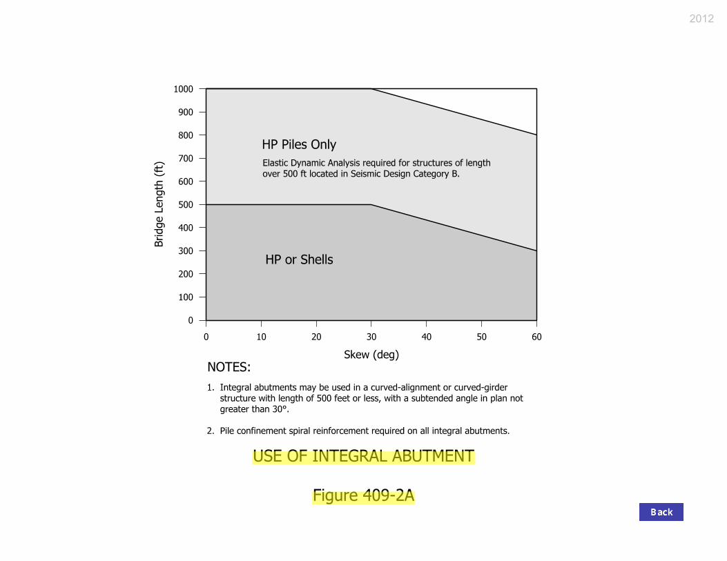


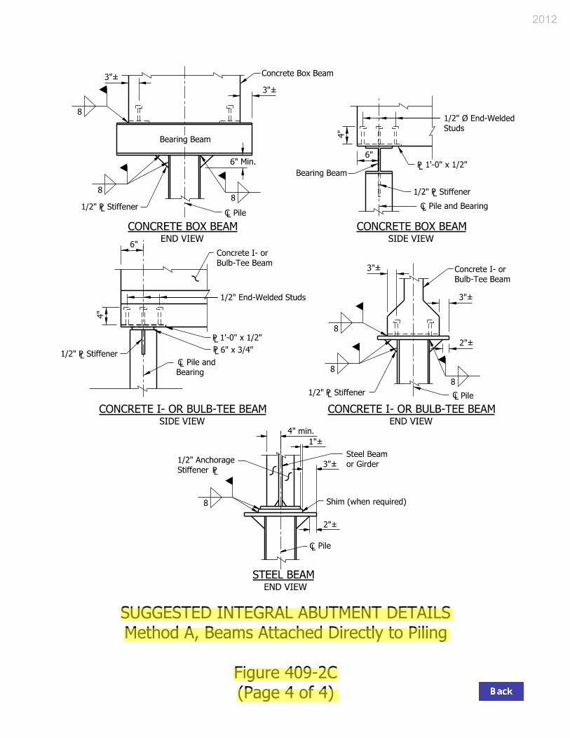

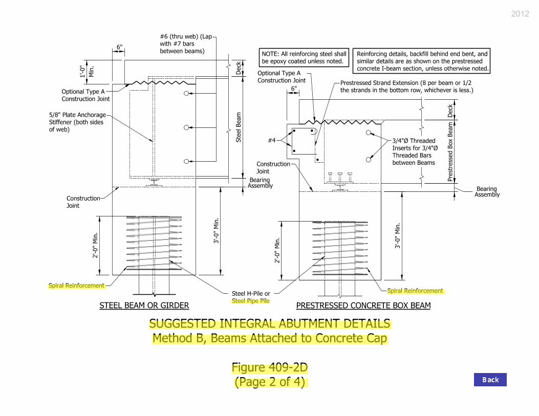

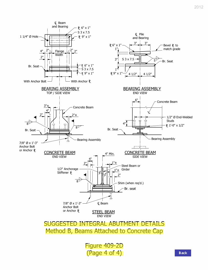


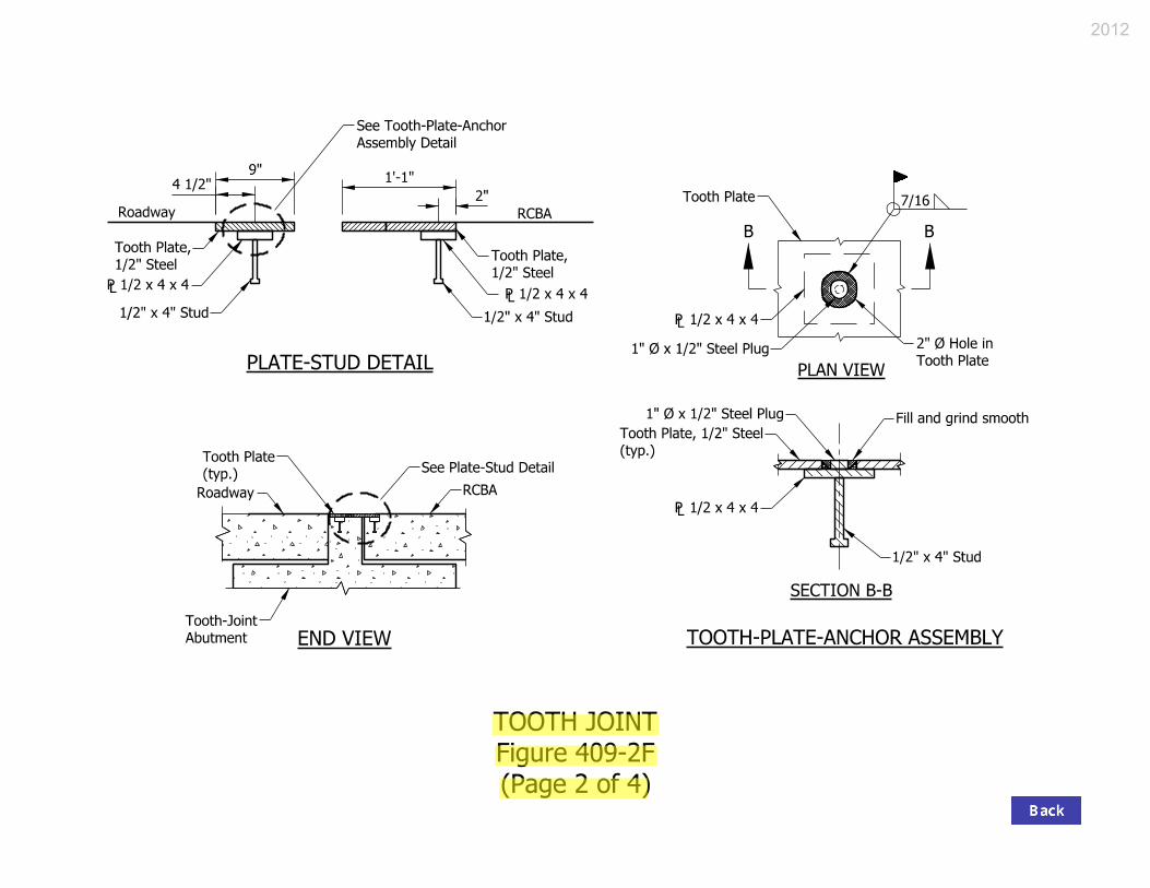
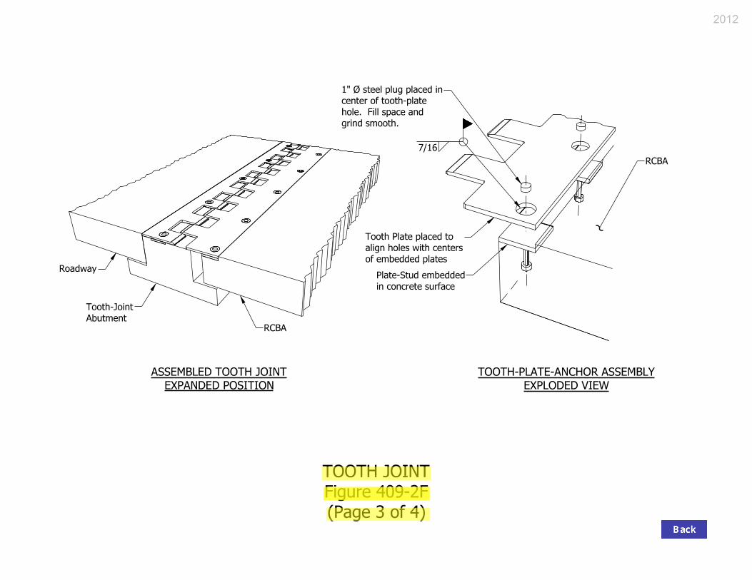


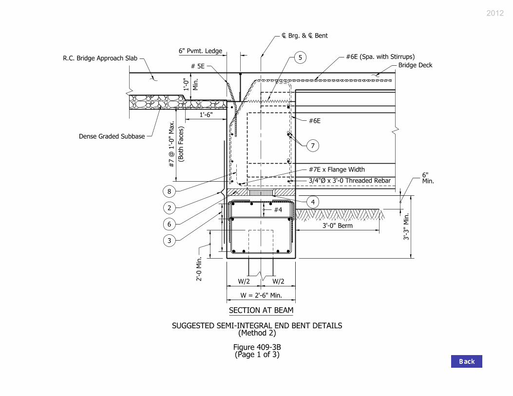


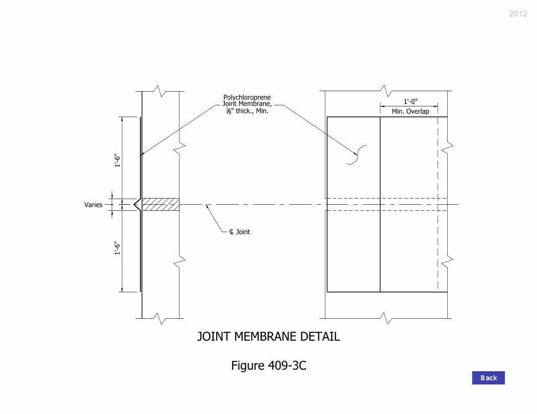


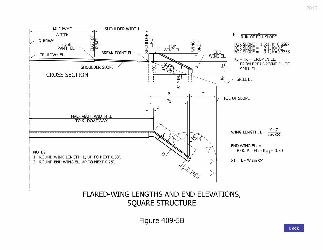

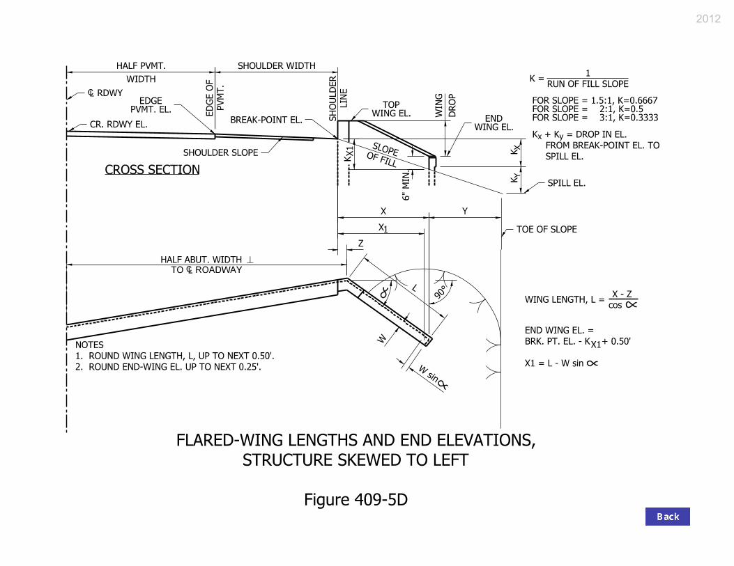


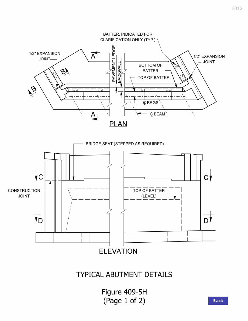


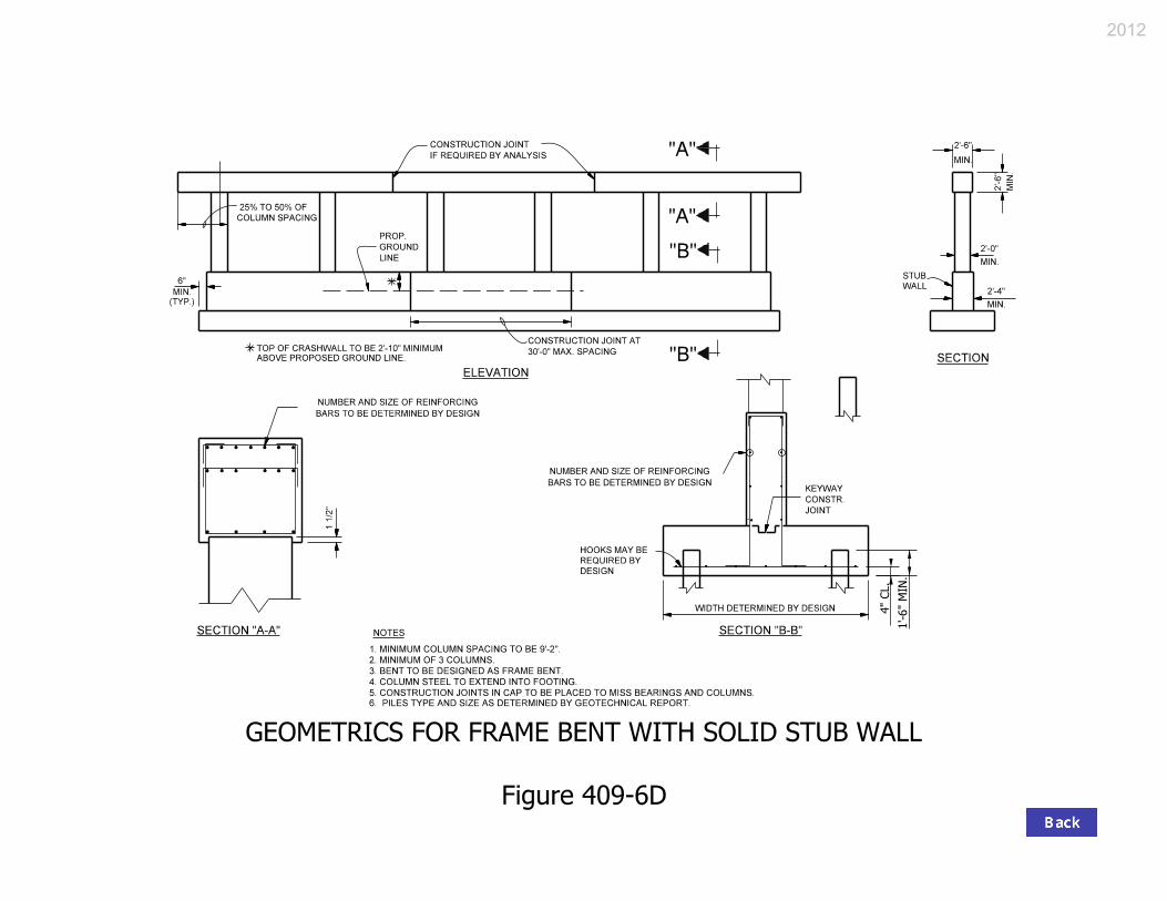
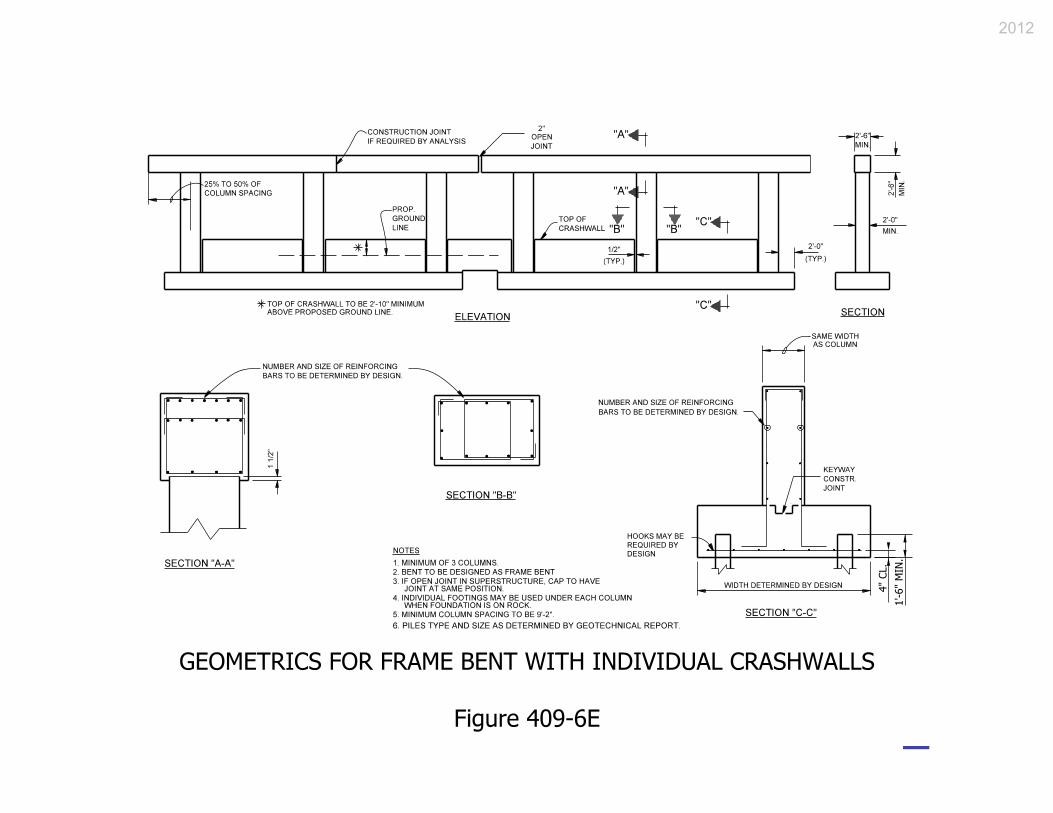
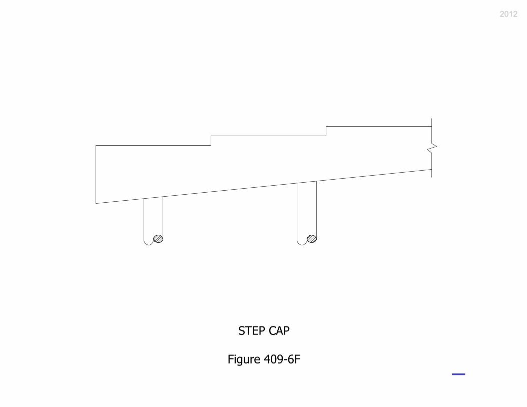
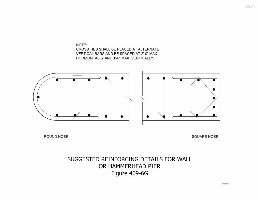
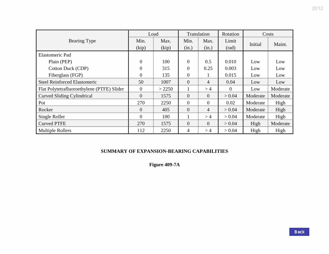


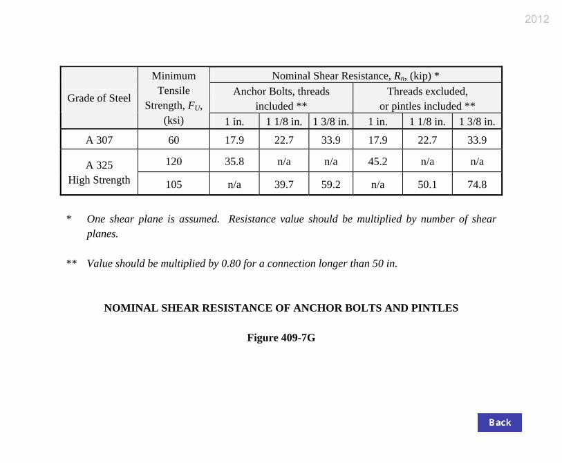

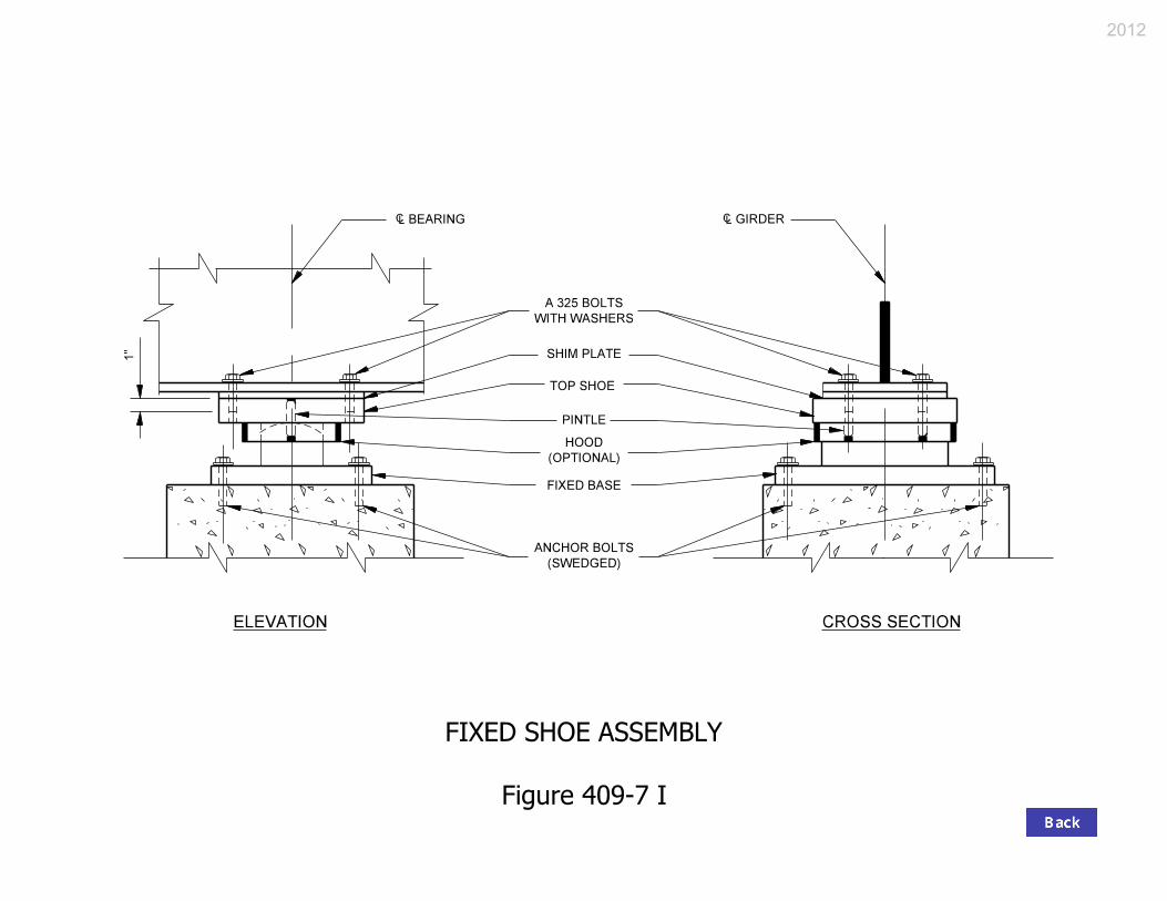


![Abutment, Bent, Pier, and Bearing 4...[Rev. Oct. 2012, Sep. 2016] 409-2E Spiral Reinforcement [Added Oct. 2012] 409-2F Tooth Joint [Del. May 2019] 409-2G Integral End Bent Placed Behind](https://static.documents.pub/doc/80x56/602404af3acfcb5cd87aa595/abutment-bent-pier-and-bearing-4-rev-oct-2012-sep-2016-409-2e-spiral.jpg)


![Abutment, Bent, Pier, and Bearing - Indiana 4/Chapter 409...409-3A Suggested Semi-Integral End Bent Details, Method 1 [Rev. Sep. 2016] 409-3B Suggested Semi-Integral End Bent Details,](https://static.documents.pub/doc/80x56/5f2b8b22b2d60c1f337daa6a/abutment-bent-pier-and-bearing-4chapter-409-409-3a-suggested-semi-integral.jpg)


