40
Safety and operation instruction AC 562

Safety and operation instruction
AC 562

- 2 -

- 3 -
1. USE OF THE MANUAL............................................................................pag. 4
2. NOTICES ON THE MACHINE..................................................................pag. 5
3. TECHNICAL DATA.....................................................................................pag. 8
4. LIFTING AND TRANSPORTATION...........................................................pag. 9
5. MAIN PARTS OF THE MACHINE..........................................................pag. 10
6. CONTROLS AND ADJUSTMENTS.......................................................pag. 12
7. ASSEMBLY INSTRUCTIONS FOR THE HANDLEBARS...............................pag. 14
8. SAFETY INFORMATION
A) GENERAL INSTRUCITONS...............................................................pag. 15
B) TRAINING..........................................................................................pag. 15
C) PREPARATION.................................................................................pag. 15
D) WORKING USE.................................................................................pag. 16
E) AFTER WORK...................................................................................pag. 17
9. TRANSPORTATION OF THE MACHINE...................................................pag. 18
10. SAFETY SYSTEMS AND GUARDS.........................................................pag. 19
11. OPERATIONS TO BE CARRIED OUT BEFORE SWITCHING ON.............pag. 19
12. STARTING AND DRIVING THE FLAIL MOWER......................................pag. 20
13. CUTTING TIPS.....................................................................................pag. 21
14. CHECKS
A) TYRE PRESSURE............................................................................pag. 22
B) CABLE CONTROL ADJUSTMENT....................................................pag. 23
C) BELT REPLACEMENT AND ADJUSTMENT........................................pag. 25
D) CHECKING AND REPLACING THE FLAILS......................................pag. 26
E) BRAKES ADJUSTMENT...................................................................pag. 27
F) SHARPENING THE FLAILS.................................................................pag. 27
G) CHECKING AND REPLACING THE TRANSMISSION OIL....................pag. 28
15. MAINTENANCE AND STORAGE............................................................pag. 29
16. CLEANING THE MACHINE....................................................................pag. 29
17. SEASONAL LONG-TERM STORAGE PERIODS.......................................pag. 30
18. DECOMMISSIONING AND SCRAPPING..................................................pag. 30
19. TECHNICAL ASSISTANCE......................................................................pag. 30
20. WARRANTY........................................................................................pag. 31
21. CE MARKING........................................................................................pag. 32
22. TROUBLESHOOTING............................................................................pag. 33
Enclosure 1. NOTESEnclosure 2. Declaration of Conformity
- FLAIL MOWER MANUAL -CONTENTS

- 4 -
Operating and Safety Instruction
FLAIL MOWER MOD. AC 562
FOREWORD
This machine may only be utilized for the purpose for which it was designed, i.e. agriculturaluse, for the cutting of shoots, grass and brushwood.Any other use other than that stated, not covered or deducible from this Manual and theenclosed Engine Manual is "PROHIBITED".Failure to comply with instructions in this Manual and in the Engine Manual releases themanufacturer from all liability, in particular for any damage resulting from improper orincorrect use, through negligence, superficial interpretation or flagrant disregard for thesafety requirements herein.Get your dealer to explain how to use the machine in optimum safety conditions.Always perform the checks as prescribed herein before each work session with the machine.Should any information given in the following pages be unclear or not straightfor-wardplease contact the manufacturer directly.
1. USE OF THE MANUALThis Manual consists of numbered pages and enclosures featured in the list of contents.Before operating the machine the user must read the instructions in the Operator's Manualcarefully as well as those of the Engine Manual enclosed.Use of the flail mower by more than one operator (individually), means that they musthave carefully read the Operator's Manual and the Engine Manual before using it.
The aforementioned manuals form an integral part of the machine and must therefore bekept intact and in good condition, in a known, easily accessible place for the entire workinglife of the machine, even if the flail mower is passed on to another owner. The purpose ofthese manuals is to provide the information necessary for the safe and competent use ofthe product. In the instance of wear or purely for a greater technical working knowledge,the manufacturer may be contacted directly. The Notes Section at the end of the Flailmower Manual is for the addition of any complementary notes.
In this Manual all safety information appears in special boxes headed “WARNING”.
WARNINGThis heading is used to draw the user's attention to hazardous areas or moving parts ofthe machine. It is also used in instances where failure to comply with the instructions givenmay result in injury to persons and animals or damage to property.

- 5 -
2. NOTICES ON THE MACHINE
The symbols affixed to the machine serving to warn of danger during its use andmaintenance are as follows:
THE USER MUST READ THE INSTRUCTION MANUAL PROVIDED
DANGER OF FOREIGN OBJECTS BEING THROWN OUTWARDS. KEEP A SAFE DISTANCE
ALWAYS DISCONNECT THE CABLE FROM THE ENGINE SPARK PLUG.
DANGER OF HAND INJURY. SWITCH OFF THE ENGINE

- 6 -
DANGER OF CRUSHING. KEEP A SAFE DISTANCE
DANGER OF INJURY TO BOTH UPPER AND LOWER LIMBS.DO NOT PUT HANDS OR FEET INSIDE THE CUTTING
ELEMENT WHILE IN MOTION
DANGER OF GETTING CAUGHT UP IN ROTATING PARTS. DO NOT PUT HANDS IN THE ROTATING PARTS
DANGER OF FOREIGN OBJECTS BEING THROWN OUTWARDS.SAFETY GOGGLES MUST BE WORN
- 7 -
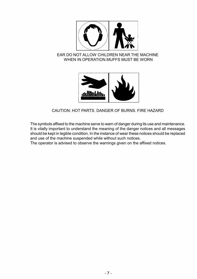
EAR DO NOT ALLOW CHILDREN NEAR THE MACHINE WHEN IN OPERATION.MUFFS MUST BE WORN
CAUTION: HOT PARTS. DANGER OF BURNS. FIRE HAZARD
The symbols affixed to the machine serve to warn of danger during its use and maintenance.It is vitally important to understand the meaning of the danger notices and all messagesshould be kept in legible condition. In the instance of wear these notices should be replacedand use of the machine suspended while without such notices.The operator is advised to observe the warnings given on the affixed notices.

- 8 -
3. TECHNICAL DATA OF THE MODEL AC 562
ENGINE: petrol HONDA GX 200
ENGINE CAPACITY: 4.1 kW
ENGINE FILTER: in oil bath
WORKING WIDTH: 50 cm
CUTTING HEIGHT: adjustable 20 - 80 mm
CUTTING SYSTEM: 24 flail rotor
SPEED GEARS: 1 forward gear - 1 reverse gear
TRASMISSION: mechanical
GEARS: in oil bath
SPEED: forward (1) 2.5 km/h
revers (1) 1.80 km/h
START: recoil
SERVICE BRAKE : on transmission pulley
ROTOR BRAKE : on rotor drive
HANDLEBARS: height adjustable
TYRES: Tractor 13 x 5.00-6
SIZE L x W x H (mm): 1500 x 580 x 1000
WEIGHT (kg): 108
ACOUSTIC PRESSURE, measured according to EN 12733 : 89 dBA
ACOUSTIC POWER, measured according to EN 12733 : LWA 98 dBA
MEASUREMENT UNCERTAINTY K 1 dBA
HANDLEBAR VIBRATION ( EN 12 733) AW : 3.8 m/s²
MEASUREMENT UNCERTAINTY U 1.8 m/s²
Environmental conditionsUnless otherwise stated at the time of ordering it is understood that the machine is to worknormally in the environmental conditions covered by the following points.Environmental conditions other than those described may cause mechanical breakageresulting in the creation of dangerous situations for persons.
- 9 -
ALTITUDE
The altitude of the place in which the machine is to be used must not exceed 1500 mabove sea level.TEMPERATURE
Minimum ambient temperature: -5°CMaximum ambient temperature:+50°CATMOSPHERIC CONDITIONS
The electrical equipment will function correctly in atmospheric conditions with a relativehumidity up to 50% at a temperature of 40°C and at 90% with a temperature up to 20°C(without condensate).ATMOSPHERE WITH RISK OF EXPLOSION AND/OR FIRE
The standard machine herein described is not designed to work in explosive atmospheresor in those with risk of fire.
4. LIFTING AND TRANSPORTATION
All material is carefully checked by the manufacturer before shipping. The flail mower isdelivered in a wooden crate or cardboard box with the handlebars disassembled.Upon receipt of the machine make sure that it has not been damaged during transit andthat the packaging has not been tampered or any parts removed. Report any damage ormissing parts immediately to the driver and the manufacturer with photographicdocumentation.
After assembling the handlebars, as per the instructions given in paragraph 7 of thismanual, the machine may be moved on its own wheels.The manufacturer is not liable for any damage caused by transportation of the machineafter its delivery.
WARNINGExtreme care must be taken during handling to prevent overturning. Avoid steep gradi-ents to prevent loss of control. Make sure that there are no persons present within thedanger area.
- 10 -
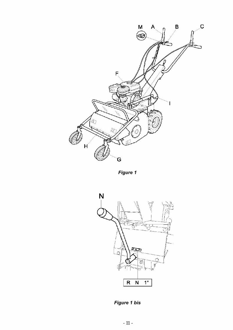
5. MAIN PARTS OF THE MACHINE
The machine consists of the following main parts:
A - FORWARD CLUTCH CONTROL LEVER
B - ACCELERATOR CONTROL LEVER
C - FLAIL ROTOR CLUTCH CONTROL LEVER
F - ENGINE
G - FRONT WHEELS
H - FRONT GUARD
I - CUTTING HEIGHT ADJUSTMENT LEVER
M - ON/OFF SWITCH (1/0)
N - GEAR SELECTOR HANDLE
- 11 -
Figure 1
Figure 1 bis
- 12 -
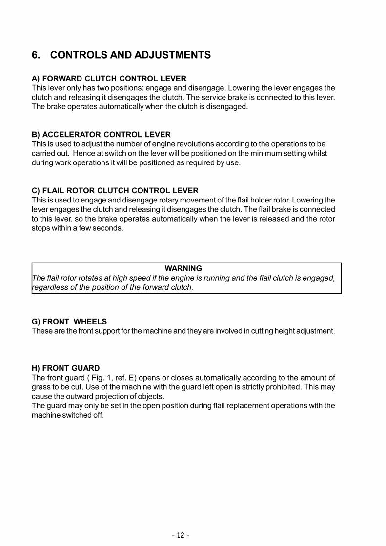
6. CONTROLS AND ADJUSTMENTS
A) FORWARD CLUTCH CONTROL LEVERThis lever only has two positions: engage and disengage. Lowering the lever engages theclutch and releasing it disengages the clutch. The service brake is connected to this lever.The brake operates automatically when the clutch is disengaged.
B) ACCELERATOR CONTROL LEVERThis is used to adjust the number of engine revolutions according to the operations to becarried out. Hence at switch on the lever will be positioned on the minimum setting whilstduring work operations it will be positioned as required by use.
C) FLAIL ROTOR CLUTCH CONTROL LEVERThis is used to engage and disengage rotary movement of the flail holder rotor. Lowering thelever engages the clutch and releasing it disengages the clutch. The flail brake is connectedto this lever, so the brake operates automatically when the lever is released and the rotorstops within a few seconds.
G) FRONT WHEELSThese are the front support for the machine and they are involved in cutting height adjustment.
H) FRONT GUARDThe front guard ( Fig. 1, ref. E) opens or closes automatically according to the amount ofgrass to be cut. Use of the machine with the guard left open is strictly prohibited. This maycause the outward projection of objects.The guard may only be set in the open position during flail replacement operations with themachine switched off.
WARNINGThe flail rotor rotates at high speed if the engine is running and the flail clutch is engaged,regardless of the position of the forward clutch.

- 13 -
M) ON SWITCHTwo-position switch:(1) for starting the engine(0) for switching off the engine
N) GEAR SELECTOR HANDLEThis handle is used to select the gears of the machine.The numbered positions indicate the gear settings ( 1 st - reverse) and the letter N indicatesthe neutral gear.
I) CUTTING HEIGHT ADJUSTMENT LEVERThis lever serves to adjust the cutting height. Warning: if the cutting height is set too low thefollowing undesirable consequences may occur:- foreign objects such as stones, etc., may be thrown outwards- dirt and mud may accumulate inside the rotor guard, thus impeding regular discharge of
cut grass.- premature flail wear and possible breakage of the same.

- 14 -
7. ASSEMBLY INSTRUCTIONS FOR THE HANDLEBARS ANDFRONT SUPPORT WITH WHEELS
The flail mower is delivered with the handlebars and front supporto with wheels disassembled.Remove the cardboard packaging or crate (to be disposed of in an appropriate manner, inaccordance with current regulations in force).To assemble, proceed as follows :
- Lift the handlebar (Fig. 2 ref. A) and insert it in the support shown in Fig. 2 ref. E.Then to fix the handlebar in the support by the screws.
- Position the support with front wheels and connect the height adjustment piece using thescrew and washer provided. Fix it to both sides on the bonnet as wellusing the screws,washers and spacers provided.
Fix the safety bar to the special holes on the two front sides of the wheel support using thescrews, washers and nuts provided.
Figure 2
Before switching on ensure that the machine has been fully assembled correctly.
- 15 -
8. SAFETY INFORMATION
Before using the flail mower it is essential that the operator has understood the warnings,do’s and don’ts and precautionary measures given in this manual and in the engine manual:the prevention of injury to the operator, third parties, animals or objects directly dependson observance of these instructions.
A) GENERAL INSTRUCTIONS Use of the flail mower for purposes other than those envisaged is strictly prohibited. Climbing aboard and/or riding on the flail mower is strictly prohibited. Tampering with the safety systems and guards is strictly prohibited. Modifications to devices/components not envisaged by the manufacturer are strictly
prohibited. The electrical parts of the engine must be protected at all times.B) TRAINING Read the Operator’s Manual and the Engine Manual before using the machine. Use of the machine by minors under the age of 16 years or by persons without the
necessary psychological and physical capabilities is forbidden. Do not use the machine near other persons or within enclosed areas. The placing of hands, other parts of the body and clothing in the moving parts of the
machine is prohibited. It is forbidden to approach the moving parts. Before carrying out any inspection or servicing operations make sure that the engine
has been switched off and the spark plug wire removed.C) PREPARATION Make sure that the working area around the machine is free of obstacles and has
sufficient lighting. Before switching on the engine make sure there are no persons, animals or vehicles in
the vicinity. Before switching on the engine make sure that both engagement levers (forward clutch
control lever - Fig. 1, ref. B and flail clutch control lever - Fig. 1, ref. A) are in thedisengaged position (released) ; the service brake will be on automatically.
Before switching on the machine make sure that the screws, fixing elements andprotection devices are in place and that the affixed notices are legible.
Then: Make sure that the wheel fixing bolts have been tightened fully. Secure all flail nuts and fixing bolts to prevent their loss during work operations. Replace
any old or worn flails. The guard in front of the flails ( Fig. 1, ref. E) must always be closed while the machine
is in use. When switching on the engine check the position of the various control levers (see the
section on “Controls and adjustments”). Supervise the clothing of personnel operating the machine: a long-sleeved jacket with
close-fitting cuffs, long, close-fitting trousers, heavy-duty footwear, and a protectivecap or helmet should be worn. Avoid wearing loose-tailed clothing, unbuttoned jacketsor torn, undone or partially zipped up items to prevent them from being caught up inthe moving parts.
Safety goggles and ear protection devices must be worn. Safety gloves must also beworn during machine operation and maintenance.
- 16 -
Do not switch on and operate the flail mower in enclosed areas since the engine givesoff carbon monoxide fumes which are colourless, odourless, tasteless and extremelydangerous.
Take care when handling fuel. Fuel is highly flammable and its vapours explosive :- Only use an approved container.- Take care not to remove fuel caps or top up the tank with the engine running.- Allow the engine to cool before proceeding with fuel-filling operations.- Do not smoke during this operation.- Never fill the machine with fuel in an indoor ambient.- It is advisable to use a wide funnel to prevent spillage of fuel on the engine and on
other surfaces of the flail mower.- If any fuel is spilled do not attempt to switch on the engine; simply move the machine
away from the area of spillage before switching on.- After filling up with fuel reposition and screw the fuel tank cap right down.
Do not rest the flail mower or the fuel container in indoor environments with nakedflames.
D) WORKING USE
When working keep everyone at a minimum distance of 10 metres from the machine. Keep the engine well ventilated and clog-free (materials and other residue) to prevent
damage to the engine and risk of fire. Clean the cooling fan and fins regularly.Clean the air filter at the same time as well.
Drive smoothly, avoiding brusque starts, braking and turns. Take care not to touch the silencer when hot. When reversing make sure there are no children or animals around. Take care not to
get caught up in the moving parts of the machine. If a slipping belt causes abnormal noise, smells or overheating, switch off the engine
immediately and check the machine to prevent the outbreak of fire and damage to thetransmission.
The rotating flails are extremely dangerous. Keep away from the rotor guard when theflails are in motion. Do not help the grass into the housing using hands or feet and donot allow anyone to stand either in front of the machine or in its direction of travel.
WARNINGDuring work operations the grass is shredded and expelled by the machine. However, ifthe grass is damp it tends to build up inside the flail housing, thus leading to the incorrectfeeding of the grass to be cut. The result is that even on short grass the engine may tendto cut out. Remove the build-up of grass inside the housing (with the engine switched off)using a stick of wood, or wait until the grass dries out before resuming cutting. If duringwork operations the engine tends to stop due to overloading, either a slower gear must beused or the cutting height must be increased, or else only part of the machine workingwidth must be used.
- 17 -
When working in a stony or obstacle-riddled area try to remove as many objects aspossible before commencing cutting. Then work at a greater cutting height than usual.
WARNINGStones and other objects may be thrown outwards in direction of the operator or of otherpersons in the vicinity. Keep at a safe distance from persons, animals and objects.
If the cutting mechanism accidentally comes into contact with an object (stump orstone), switch off the engine and carry out the following operations:- Inspect the damage.- Do not attempt to repair it if unskilled to do so.- Check that no parts have come loose.
Do not use the machine if it does not work properly or is broken: seek authorizedservice.
It is strictly prohibited to leave the flail mower running whilst unsupervised. It is strictly prohibited to transport the machine with the engine running. When loading
the machine onto a vehicle, the inclination of the ramps must not exceed 15°.
WARNINGEXERCISE CAUTION WITH GRADIENTS . Danger of machine overturning.
Given its outdoor use, it is advisable not to use the flail mower when it is raining. The area next to the engine exhaust may reach a high temperature.
WARNINGDanger of burns.
Do not go near water fountains or precipices and do not cross narrow bridges duringwork operations to prevent the risk of falling.
Do not work on steep banks with gradients in excess of 10°. Take special care on steep banks; avoid working upstream of the machine so as not to
run the risk of slipping under it, particularly when the ground is wet. Avoid working on the shoulder, between flat ground and a steep bank. The machine
may skid or slip. In the instance of difficulty or emergency stop simply release the forward clutch control
and flail rotor levers. Work on flat ground for the utmost safety.
E) AFTER USE Before moving away from the machine, switch off the engine by moving the switch
(Fig.1 bis,ref.I) to the 0 position. For greater safety shut off the feed cock (Fig. 3).

- 18 -
9. TRANSPORTATION OF THE MACHINE
LOADING AND UNLOADING FROM A VEHICLE
For transportation it is preferable to use a vehicle with an open bed. Choose firm, flat ground. Switch off the vehicle’s ignition, put into reverse gear, pull on the hand brake and block
the tyres with chocks to prevent accidental movement of the vehicle.
WARNINGRaise the flail mower cutting unit to maximum height to prevent danger of its catching theramp edges.
Do not stand in front of the machine Firmly hook the loading ramps onto the vehicle bed.
Use stable load ramps with a non-slip surface strong enough to take the weight of themachine.The inclination of the ramps must not exceed 15°.Recommended length : at least 31/
2 times the vehicle bed’s height from the ground.
Recommended width : to be chosen according to the tyre width of the machine Proceed with the loading of the machine, manoeuvring it carefully. Set the accelerator
lever at minimum (Fig. 1, ref. C) During loading/unloading operations on the ramps avoid operating the flail clutch
(Fig. 1, ref. A), and the right and left wheel release levers (fig. 1, ref. F and F1) becausesuch actions may prove extremely dangerous.
Line the front slide up with the centre of the loading ramps. Take care when the machine passes from the loading ramps to the vehicle bed, because
a shift in balance occurs. Once loaded, turn off the engine using the relative switch (Fig. 1 bis, ref. I), make sure
that the service brake has automatically come into operation upon release of the forwardclutch control lever ( fig. 1, ref. B), block the machine wheels using chocks and firmlytie the machine to the vehicle.

- 19 -
10. SAFETY AND GUARD SYSTEMS
WARNINGThe safety devices must never be tampered with. It is necessary to understand how theywork and safeguard their efficiency and correct operation. In the in-stance of doubt,problems or malfunction contact your dealer.
FORWARD CONTROL AND FLAIL MOVEMENT LEVERSWhen released both of these levers instantly disengage the transmission connected tothem, thus automatically engaging their respective brakes, hence the machine servicebrake in the first case and flail rotor rotation in the second.In this way they act as safety devices.In the instance of difficulty or sudden emergency, the quick release of these levers willreturn them to their standard position (raised).
FRONT GUARDThe front guard (Fig. 1, ref. E) opens or closes automatically according to the amount ofgrass to be cut. Use of the machine with the guard left open is strictly prohibited. This maycause the outward projection of objects.The guard may only be set in the open position during flail replacement operations withthe machine switched off.
11. OPERATIONS TO BE CARRIED OUT BEFORE SWITCHING ON
Position the flail mower outdoors on sufficiently firm, flat soil. Read the instructions providedby the engine manufacturer in the relative manual and follow them carefully to prevent situationsarising which may endanger either persons or the machine.Then check:- the state of the flails by inspecting them;- that all the screws are tightened, particularly those securing the flails;- that the guards and safety devices are securely tightened.- that there are no persons in the vicinity.During operation do not allow persons near the machine, especially children. The operatoris responsible for any harm done persons in the working area of the machine.
Oil recommendationsBefore switching on the engine check the oil level and top up, if necessary,while keeping it in a horizontal position. Do not overfill.Use of a high-grade detergent oil is recommended (Ref.er to the enclosed engine manual).Fuel recommendationsUse of fresh, clean lead-free petrol is advised.
WARNINGIt is advisable to consult the engine manual before swithcing on the machine.
- 20 -
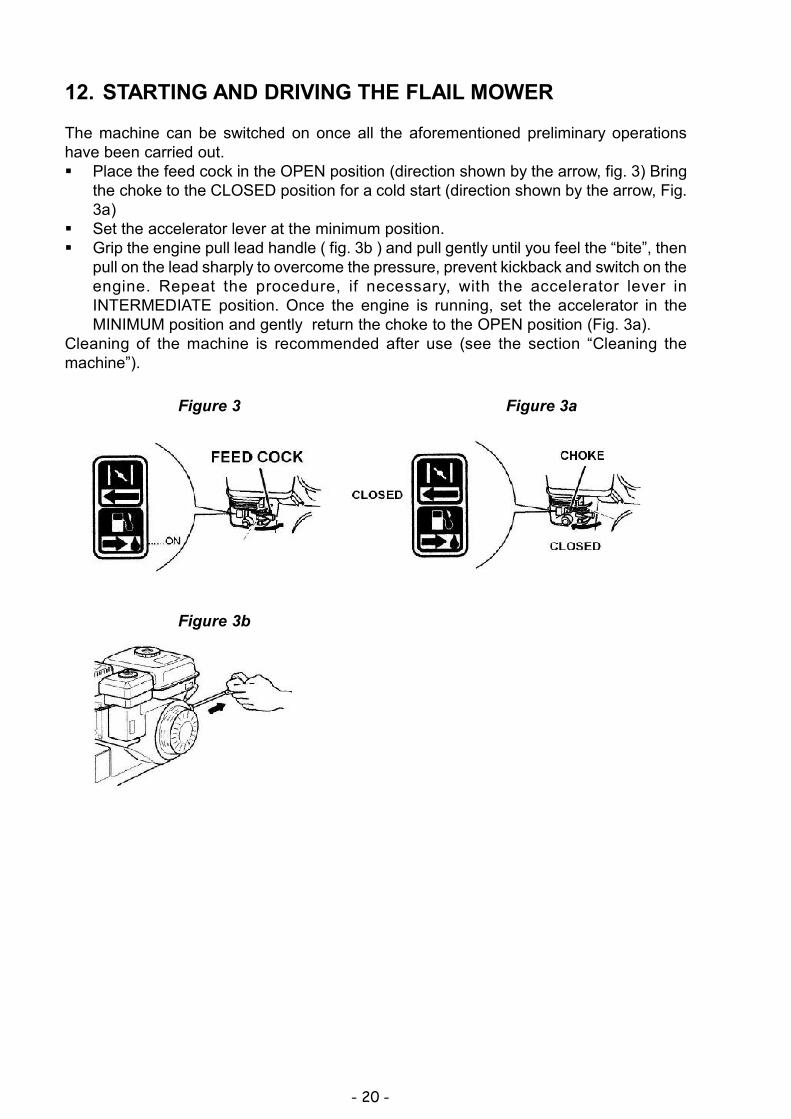
12. STARTING AND DRIVING THE FLAIL MOWER
The machine can be switched on once all the aforementioned preliminary operationshave been carried out. Place the feed cock in the OPEN position (direction shown by the arrow, fig. 3) Bring
the choke to the CLOSED position for a cold start (direction shown by the arrow, Fig.3a)
Set the accelerator lever at the minimum position. Grip the engine pull lead handle ( fig. 3b ) and pull gently until you feel the “bite”, then
pull on the lead sharply to overcome the pressure, prevent kickback and switch on theengine. Repeat the procedure, if necessary, with the accelerator lever inINTERMEDIATE position. Once the engine is running, set the accelerator in theMINIMUM position and gently return the choke to the OPEN position (Fig. 3a).
Cleaning of the machine is recommended after use (see the section “Cleaning themachine”).
Figure 3 Figure 3a
Figure 3b

- 21 -
WARNINGTake great care because the flails rotate at very high speed.
DRIVING THE MACHINE
WARNINGWhen using the machine for the first time it is advisable to get the feel of it by executingmanoeuvres on flat ground free of foreign objects. Cut in a straight line at low speed,slightly overlapping the section cut previously.
After switching on the engine following the instructions given in the previous paragraph:
1. Engage the flail rotor clutch control lever ( Fig. 1, ref. A) after accelerating a little.
WARNINGSelect a suitable cutting height to prevent the flails from striking foreign objects.
2. To move the machine, accelerate and then engage the forward clutch using the relativelever (Fig. 1, ref. B).
3. To stop the flails release the relative lever ( Fig. 1 ref. A); the flail rotor brake willfunction automatically.
4. To stop the machine, release the relative lever (Fig. 1 ref. B); the service brake willfunction automatically.Then switch off the engine by moving the switch to the position (O) as shown in figure1 bis, ref. I).
5. To move the machine with the engine switched off, disengage both wheel locks usingthe levers as shown in figure 1, ref. F and F1.Warning: to use the wheel release mechanism consult the section “Main parts of themachine”, refs. F and F1.
1. Before commencing cutting operations, read the safety instructions given in the previoussections.
2. Before engaging flail movement using the relative lever ( figure 1, ref. C) the guard ( fig.1, ref. H) must be fully lowered to prevent the outward projection of objects.
3. At first the setting of a relatively high cutting height is recommended (using the relativelever in figure 1, ref. I), lowering it gradually according to working conditions.
4. Engage the flail clutch (Fig. 1, ref. C) only after having carried out the machine switch-onand gear engagement operations.
5. Before engaging the flail clutch (Fig. 1, ref. C), gradually move the accelerator (Fig. 1, ref.B) until the required speed is reached.
6. Engage the flail clutch (Fig. 1, ref. C) gradually. Overly brusque flail clutch engagementmay stall the engine.
13. CUTTING TIPS
- 22 -
14. CHECKS
- Adjust the belt and cable control tension after the first few working hours to compensateinitial loosening.
- Briefly operate all the machine’s components to detect any abnormal noises oroverheating.
- During the initial running in period avoid heavy-duty usage to encourage proper settlingof the mechanical parts.
- Never neglect maintenance operations after work and carry out all prescribed checks
regularly.
A) TYRE PRESSURERegularly check the tyre pressure. (1.8 bar - 23 psi ). If both two tyres are not inflated to average pressure the machine will tend to travel sidewaysduring operation.
WARNING!ANY COMPLEX JOB AND ANY WORK AFFECTING THE SAFETY OFTHE OPEATOR AND/OR OTHER PERSONS MAY ONLY BE CARRIED
OUT AT AN AUTHORISED SERVICE CENTRE

- 23 -
B2) BLADE ROTOR CONTROL CABLE
The cable is controlled by the lever located on the handlebar as show Fig 5 Rif. D.Operating the lever acts on both at the same time: the blade rotor mmoves, its brakebecomming disengaged.For optimum regulation, follow the instructions, as described in sections C1 e D1.
B3) FORWARD CONTROL CABLEBRAKE CONTROL CABLE
Both cables are controlled at the same time by the lever located on the handlebar.(Fig.5 RifA).Operating the lever acts on both cables at the same time: the forward motion of the machineis engaged and the parking brake disengaged.For optimum regulation, follow the instructions, as described in sections C2 and D2.
Figure 5
A forward leverB forward cableC forward brake cableD rotor engagement leverE Rotor engagement cable
B) CABLE CONTROL ADJUSTMENTTo adjust the cables place the machine on flat ground, switch off the engine and disconnectthe wire from the spark plug.
- 24 -
Figure 7
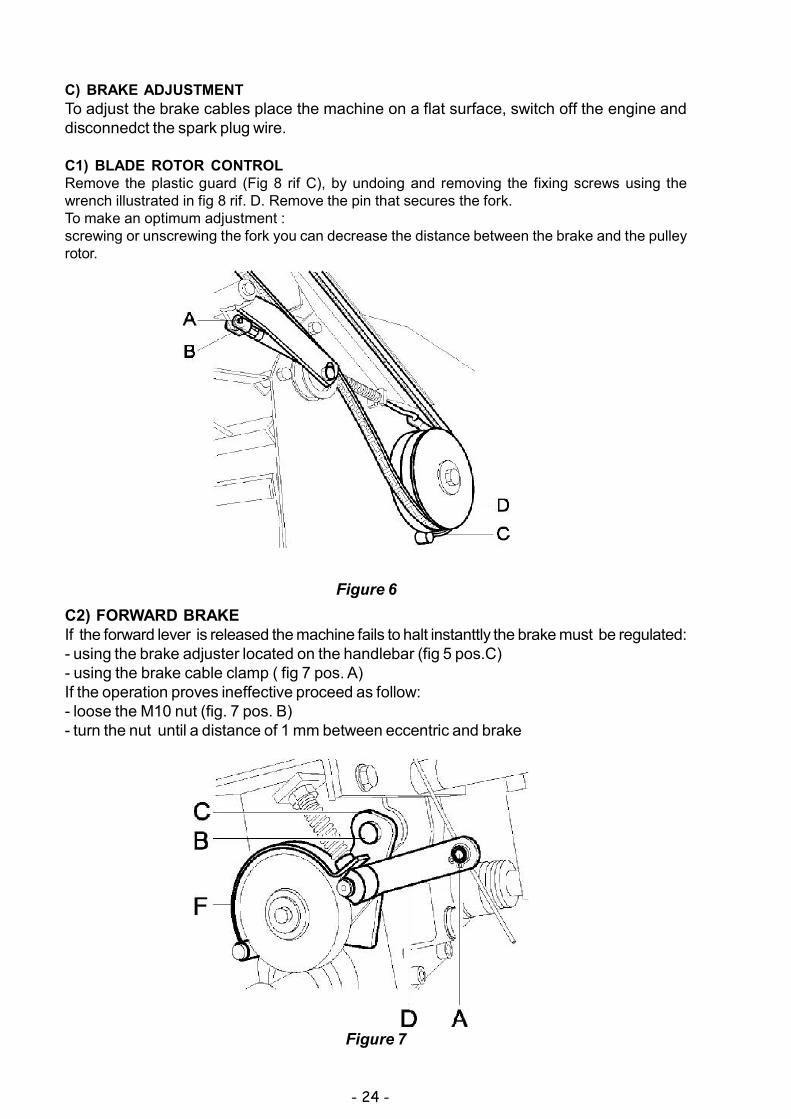
C2) FORWARD BRAKEIf the forward lever is released the machine fails to halt instanttly the brake must be regulated:- using the brake adjuster located on the handlebar (fig 5 pos.C)- using the brake cable clamp ( fig 7 pos. A)If the operation proves ineffective proceed as follow:- loose the M10 nut (fig. 7 pos. B)- turn the nut until a distance of 1 mm between eccentric and brake
C) BRAKE ADJUSTMENT
To adjust the brake cables place the machine on a flat surface, switch off the engine anddisconnedct the spark plug wire.
C1) BLADE ROTOR CONTROLRemove the plastic guard (Fig 8 rif C), by undoing and removing the fixing screws using thewrench illustrated in fig 8 rif. D. Remove the pin that secures the fork.To make an optimum adjustment :screwing or unscrewing the fork you can decrease the distance between the brake and the pulleyrotor.
Figure 6

- 25 -
Figure 8
D2) FLAIL ROTOR BELT
- Remove the plastic guard ( fig. 8 ref.C), by undoing and removing the fixing screws usingthe wrench illustrated in 8 ref. D.
- If the belt ( fig. 9 ref. E) is slack and therefore unable to ensure proper drive to the flailrotor, move the tightener ( fig. 9, ref. F) from the lower hole ( hole G ) to the upper hole (hole H).
- If the belt is worn or breaks it should be replaced.
Figure 9
D) BELT REPLACEMENT AND ADJUSTMENT
D1) BLADE ROTOR DRIVE BELT- Remove the plastic guard, by unscrewing and taking out the screws shown using the
wrench illustrated in fig. 8 pos D- If the belt ( fig. 9 ref. A) is slack and therefore unable to ensure proper drive to the flail rotor,
move the tightener ( fig. 9, ref. B) from the lower hole ( hole C ) to the upper hole ( hole D).- If the belt is worn or breaks it should be replaced.
WARNING
After having made the adjustments as described above, check that flail rotor brake is stillworking properly, stopping roller movement immediately.

- 26 -
D) CHECKING AND REPLACING THE FLAILSAlways check the state of the flails before commencing work. Do not forget to switch theengine off!
Checking and replacement of the flails requires the assistance of another person to holdthe handlebars down to tilt up the front part of the machine.The flails will be presented as shown in figure 10.
- During work operations if the flails (Fig. 10, ref. A ) strike stones or stumps stopstraightaway and make sure that they have not become bent or broken. Damagedflails must be replaced.
- If the flails are very worn, cracked or bent, they make snap and project objects outwards,risking serious accident.
- It requires specific experience and suitable equipment to replace and repair flails.- Use heavy-duty work gloves to check or replace the flails to avoid risk of injury to
hands.- The flail fixing screws and relative nuts ( fig. 10, ref. B) are also subject to wear.
Always replace them at the same time as the flails, using bolts and screws of thesame strength and type.
- When some of the flails are broken or bent they give rise to excessive vibration athigh speed.
- The flails are reversible, so when they become blunt on one side they can be assembledon the other.
- Generally speaking, unless it’s a question of only 1 or 2 flails, all the flails should bereplaced at the same time to prevent the occurrence of vibration.
- Even the flail rotor holder (fig. 10, ref. C) may cause vibration. If so, it should bereplaced.
- The flails wear more quickly on dry, sandy ground. In these conditions they should bereplaced more frequently.
It is advisable to keep spare flails handy.
Figure 10

- 27 -
E) BRAKES ADJUSTMENTThe two brakes are correctly adjusted when the flail rotor lever ( fig. 4, ref. B) and forwardcontrol lever ( fig. 4, ref. C) have 5 mm of play as indicated under the section “ADJUSTMENTOF THE CONTROL CABLES”. Should the said brakes fail to perform their safety functionafter correct lever adjustment, check the state of wear of the brake lining and replace thebrakes if necessary.
F) SHARPENING THE FLAILSTo sharpen the flails proceed as follows:
1. Wear a safety helmet, goggles and heavy-duty work gloves. Work with care.2. Hold the flail firmly.3. Do not grind parallel to the cutting edge. Do not grind the cutting edge to razor
sharpness; leave a flat edge of 0.4-0.6 mm. If honed to razor sharpness the cuttingflail will wear down very quickly.
4. Grind all the flails in the same way so as to maintain rotor balance.5. When grinding the flail only remove a little material at a time and spray with water to
lower the temperature. If the flail overheats during sharpening it will lose temper andbecome less wear resistant.
6. If the rotor is off balance after the flails have been sharpened the resulting vibrationsmay damage the machine.
To remove the flails proceed as follows:
1. Switch off the engine and disconnect the spark plug wire2. Adjust the cutting height to maximum3. Open the front housing.4. Check the state of the flails.5. Check that the flails are not cracked, bent, excessively worn or broken. If they are,
either reverse them (turning them 180°) or replace them.
- 28 -
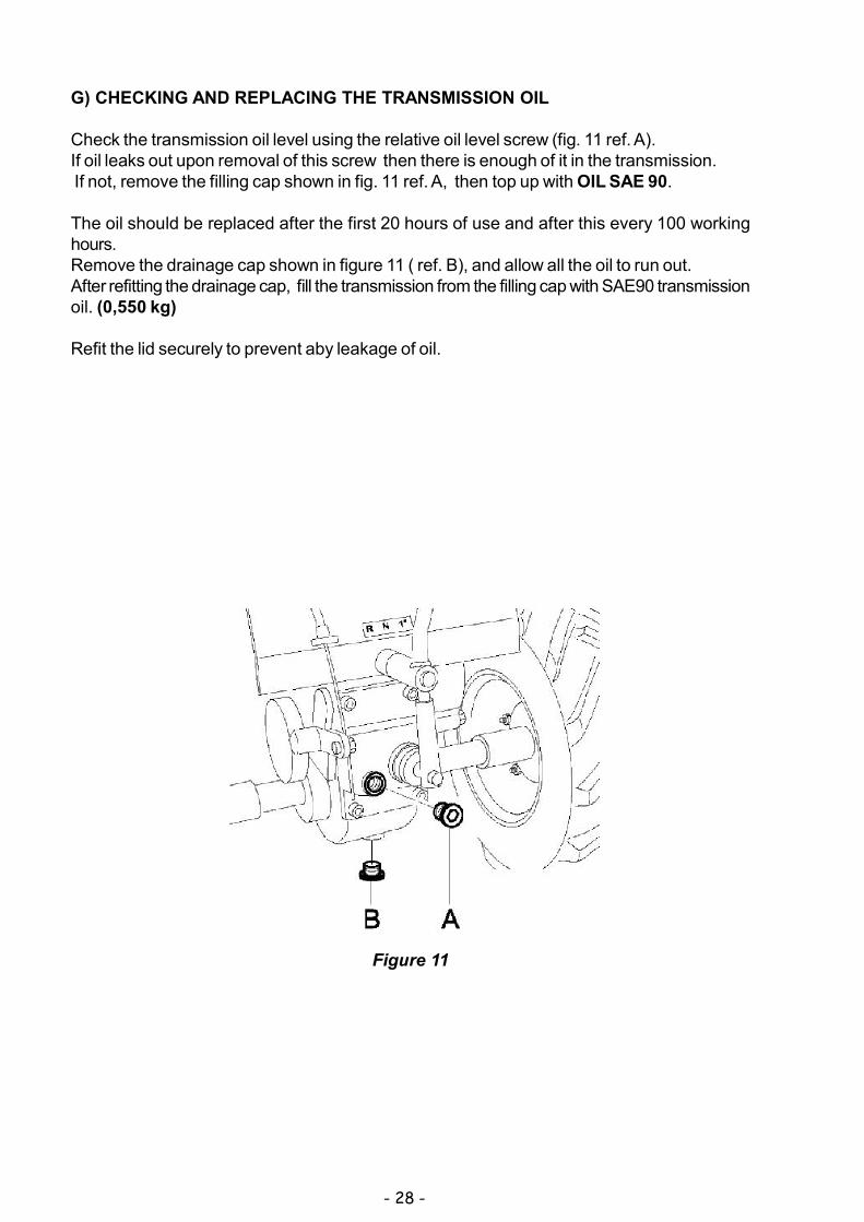
G) CHECKING AND REPLACING THE TRANSMISSION OIL
Check the transmission oil level using the relative oil level screw (fig. 11 ref. A).If oil leaks out upon removal of this screw then there is enough of it in the transmission. If not, remove the filling cap shown in fig. 11 ref. A, then top up with OIL SAE 90.
The oil should be replaced after the first 20 hours of use and after this every 100 workinghours.Remove the drainage cap shown in figure 11 ( ref. B), and allow all the oil to run out.After refitting the drainage cap, fill the transmission from the filling cap with SAE90 transmissionoil. (0,550 kg)
Refit the lid securely to prevent aby leakage of oil.
Figure 11

- 29 -
15. MAINTENANCE AND STORAGE
All operations on the machine must be carried out exclusively by authorized personnel. Always switch off the engine when checking, adjusting or servicing the machine. Allow the machine to cool down before inspection. The belt guards (Fig. 8 ref.C) and flail guards ( Fig. 1 ref. H) must always be correctly
installed and intact. If they become damaged, have them repaired before the machine isused again.
Make sure that all the guards of rotating and moving parts are in place. For greater safety, when replacing the flails replace all the fixing screws and nuts at
the same time, as described in section 14, point D. Inspect the fuel lines. These should be replaced if damaged or after a maximum of
three years, along with the fixing bands. Old lines may leak fuel. Check and regularly adjust the forward clutch control, flail clutch control, brakes and
accelerator. Cover the machine with a sheet after the engine and silencer have cooled down. Have the flail and service brakes replaced by an authorized workshop if their safety
function does not work perfectly. It is strictly forbidden to place/leave unattended on the flail mower any potentially
dangerous objects which may put the safety of persons or the machine at risk. Keep the machine in a good, clean state; do not leave it outside exposed to inclement
weather conditions. After use store the machine in a place where children have no access. Always allow
the machine to cool down before putting it away. After use store the machine in a place where fuel vapours cannot reach a naked flame
or sparks. In the instance of a long period of non-use, drain the fuel tank completely.
Use of the machine does not require specific lighting.However, the recommended minimum amount of light (e.g. 200 lux) is enough to be ableto read the notices on the machine and to operate it without running risks caused by poorlight.
16. CLEANING THE MACHINE
- Switch off the engine and disconnect the spark plug wire;- Clean the engine and the outside of the machine with a cloth soaked in a little oil.- Clean all parts of the machine, particularly the starting unit, air filter, exhaust and
carburetor. It is advisable to follow the instructions given in the engine manual.- Clean the inside of the belt guard (fig. 8, ref.C) with a blast of compressed air.- To clean the inside of the flail guard ( fig. 1 ref. H), wash with a jet of water straight after use
while still damp.When washing carefully cover and protect the electrical parts of the engine, thecarburetor, the air filter and the exhaust from the water to prevent engine problems.
- To clean the flail area a tool should be used (stick of wood).
- 30 -
17. SEASONAL LONG-TERM STORAGE PERIODS
To store the flail mower for prolonged periods of non-use, proceed as follows:
- Park the machine on flat, firm, clean ground.- Oil deposits on the ground where the machine is positioned may cause irreparable
damage to the tyres.- Disconnect the spark plug wire;- Clean the machine carefully as described in section “Cleaning the machine”- Make sure that all screws and nuts are fully tightened.- Retouch with paint any parts which have become exposed during use.- Store the machine in a clean, dry place.- Empty the fuel tank, following the instructions given in the engine manual;- Regularly check the tyre pressure, and adjust if necessary.- Lubricate all moving parts and have any necessary repairs to the machine carried out
18. DECOMMISSIONING AND SCRAPPING
After the working life of the flail mower the user must have it dismantled and its componentsremoved as per EEC directives or in accordance with current legislation in force in hiscountry, taking particular care over the dismantling of the following materials ofenvironmental impact:
- plastic parts- rubber parts- coated electric wiring- petrol engine- metal parts- toxic substances
19. TECHNICAL ASSISTANCE
Routine maintenance must be carried out as per the instructions given in this Manual. Forany instances not covered herein and for technical assistance in general contact yourdealer referring to the data given on the identification plate affixed to the machine.The right reference will ensure swift, precise answers.For swift delivery of spare parts always quote the following information on the order:- Machine model and serial number- Part description and quantity required
For assistance concerning the engine it is advisable to contact the service centre authorizedby the engine manufacturer (see engine manual supplied).

- 31 -
20. WARRANTY
The flail mower has a 12-month warranty which starts from the day of purchase, (or up to50 hours’ service, if for individual use) or 6 months (or up to 50 hours’ service, if forcommercial use) excluding the engine, for which the warranty supplied by its manufacturerapplies.The manufacturer will replace free of charge any parts it acknowledges to be faulty. Labourand transportation costs are to be paid by the customer.For any problems or repair enquiries please contact your dealer. Warranty applicationsmust be forwarded to the manufacturer via the dealer.Any damage during transit must be reported to the dealer immediately.
As regards any materials not manufactured by us, particularly the engine, the regulationsof the respective manufacturers apply. So, any applications for repairs must be forwardedto the specific service centres within those specific areas.
If maintenance work carried out on the machine does not conform to the instructionsprovided, involving the use of non-original spare parts or without the written authorizationof the manufacturer, thus jeopardizing the integrity of the machine or changing itscharacteristics, the manufacturer will not be liable for the safety of persons or for thefaulty operation of the machine.All unauthorized modifications to the machine invalidate the warranty agreement.
- 32 -
Figure 13
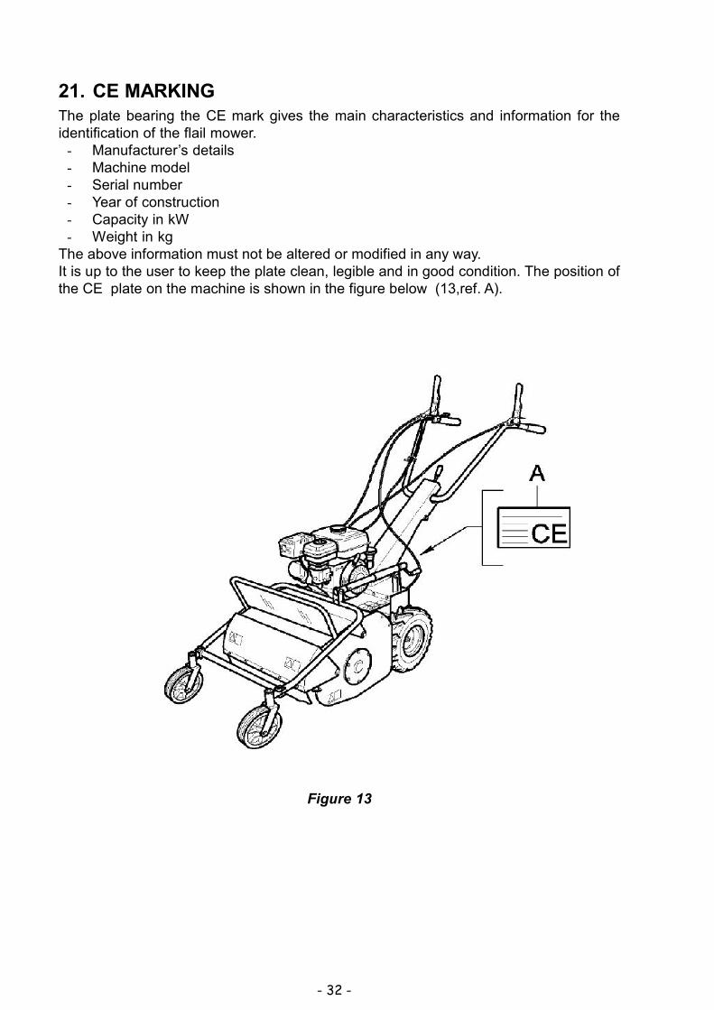
21. CE MARKINGThe plate bearing the CE mark gives the main characteristics and information for theidentification of the flail mower.
- Manufacturer’s details- Machine model- Serial number- Year of construction- Capacity in kW- Weight in kg
The above information must not be altered or modified in any way.It is up to the user to keep the plate clean, legible and in good condition. The position ofthe CE plate on the machine is shown in the figure below (13,ref. A).

- 33 -
22. TROUBLESHOOTINGThe following table illustrates some problems which may arise during operation.
FAULT CAUSE MEASURES TO BE TAKEN Grass ejection insufficient 1. Grass wet
2. Grass too long 3. Cutting height too low 4. Engine speed too low 5. Forward speed too high 6. Build-up of grass inside flail
housing
1. Wait until the grass has dried
2. Go over the grass twice, changing the cutting height
3. Increase the cutting height 4. Accelerate to maximum 5. Decrease forward speed 6. Clean the inside of the flail
housing Machine does not cut the grass completely
1. Forward speed too high 2. Engine speed too low 3. Grass too long 4. Flails worn or broken 5. Build-up of grass inside flail
housing
1. Decrease forward speed 2. Accelerate to maximum 3. Go over the grass twice,
changing the cutting height 4. Replace the flails 5. Clean the inside of the flail
housing Machine scalps the ground 1. Cutting height too low
2. Undulating terrain 3. Ground uneven
1. increase the cutting height 2. change cutting pattern
(e.g. direction) 3. increase cutting height
Belt slips 1. belt tension inadequate 2. Build-up of grass inside flail
housing 3. Belt worn
1. Adjust the belt tension 2. Clean the inside of the flail
housing 3. Replace belt
Machine vibrates excessively 1. Build-up of grass inside flail housing
2. Belt damaged 3. Flails bent or broken 4. Flail rotor warped
1. Clean the inside of the flail housing
2. Replace belt 3. Replace flails 4. Replace rotor
Engine overloads during work operations
1. Engine speed too low 2. Flails worn 3. Forward speed too high 4. Snarl or build-up of grass
on rotor 5. Grass too long 6. Cutting height too low
1. Accelerate to maximum 2. Invert or replace flails 3. Decrease forward speed 4. Remove grass from flail
rotor 5. Go over the grass twice,
changing the cutting height 6. increase the cutting height
Machine tends to run away on steep banks
1. ground too soft 2. operator cutting at right
angles to bank
1. wait until ground dries 2. work in direction of bank
The cutting unit projects objects outwards
1. front guard raised 2. front cover open 3. working in reverse gear
1. lower the front guard 2. close front cover firmly 3. only work in forward gear

- 34 -
ENGINE
FAULT CAUSE MEASURES TO BE TAKEN
Engine sluggish at switch on 1. accelerator not in start-up position
2. Choke not closed 3. Petrol does not arrive 4. Air bubbles or water inside
the petrol lines 5. Thick oil prevents rotation 6. Winding or start
mechanism faulty 7. Spark plug in poor
condition
1. move the accelerator to the intermediate position
2. Close the choke when cold. 3. Check the fuel tank and
remove any water or sediment. Make sure that the feed cock is open.
4. Check the lines and bands. Repair or replace if damaged
5. Use oil with a viscosity suited to the temperature
6. Replace winding or start mechanism
7. Clean or replace spark plug. Adjust the distance between the electrodes.
Poor power 1. No fuel 2. Air filter blocked 3. Elastic bands worn
1. Refill the tank 2. clean air filter 3. replace elastic bands
Engine stalls 1. no fuel 2. feed cock shut off
1. Refill tank with petrol 2. open feed cock
Exhaust fumes dark 1. low grade fuel 2. too much engine oil
1. replace with high grade fuel 2. restore engine oil to correct
level
Engine emits black smoke and power is poor
1. air filter blocked 2. choke not fully opened
1. clean air filter 2. open the choke completely
Exhaust fumes bluish 1. too much engine oil 2. Elastic bands worn
1. restore engine oil to correct level
2. replace elastic bands
Silencer becomes red through overheating
1. Air filter blocked 2. Inside of self-winding
starter blocked with grass cuttings
1. clean air filter 2. clean self-winding starter
housing
For any problems not easily resolved or in case of doubt you are advised to contact yourdealer.

- 35 -
NOTES_________________________________________________________________
_________________________________________________________________
_________________________________________________________________
_________________________________________________________________
_________________________________________________________________
_________________________________________________________________
_________________________________________________________________
_________________________________________________________________
_________________________________________________________________
_________________________________________________________________
_________________________________________________________________
_________________________________________________________________
_________________________________________________________________
_________________________________________________________________
_________________________________________________________________
_________________________________________________________________
_________________________________________________________________
_________________________________________________________________
_________________________________________________________________
_________________________________________________________________
_________________________________________________________________
_________________________________________________________________
_________________________________________________________________
_________________________________________________________________
_________________________________________________________________
_________________________________________________________________
- 36 -
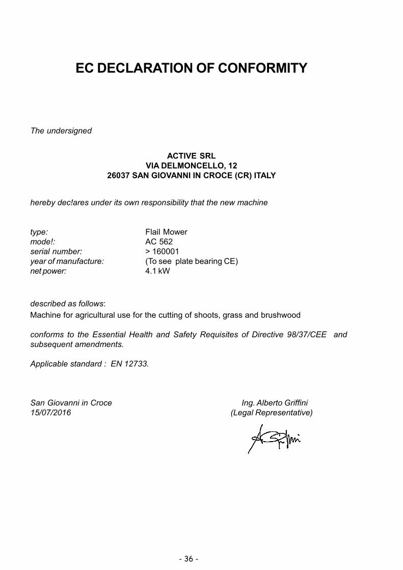
The undersigned
hereby dec!ares under its own responsibility that the new machine
type: Flail Mowermode!: AC 562serial number: > 160001year of manufacture: (To see plate bearing CE)net power: 4.1 kW
described as follows:
Machine for agricultural use for the cutting of shoots, grass and brushwood
conforms to the Essential Health and Safety Requisites of Directive 98/37/CEE andsubsequent amendments.
Applicable standard : EN 12733.
San Giovanni in Croce Ing. Alberto Griffini15/07/2016 (Legal Representative)
EC DECLARATION OF CONFORMITY
ACTIVE SRLVIA DELMONCELLO, 12
26037 SAN GIOVANNI IN CROCE (CR) ITALY

- 37 -

- 38 -

- 39 -

ACTIVE s.r.l. Via Delmoncello, 12 - 26037 S. Giovanni in Croce (CR)
Tel. 0375-91742 - Fax 0375-91684
email ITALY : [email protected] EXPORT : [email protected]
www.active-srl.com


