THE AC C T LE1SION RECEIVER PRACTICAL TELEVISION AND TELEVISION TIMES A N Armatioesaii. Vol. 3 No. AUGUST 19 2 FEATURED IN THIS ISSUE 14 . us " Queries An red Manufacture of CR. Tubes -Strays and Losses o ing the TV in the Classroom Franco-British TV
Transcript
THE AC C T LE1SION RECEIVER
PRACTICAL TELEVISION
AND TELEVISION TIMES
A N Armatioesaii. Vol. 3 No. AUGUST 19 2
FEATURED IN THIS ISSUE 14 . us " Queries An red Manufacture of CR. Tubes
-Strays and Losses
o ing the TV in the Classroom Franco-British TV
PRACTICAL TELEVISION August, 1952
LT he specification A L9Oo
AERIAL
ELEMENTS77
INSULATORS
MAST
_BRACKETS J rt
MODEL 55
ELEMENTS- constructed in light high Tensile duralumin fully heat treated and tempered. These elements are filled to prevent humming and processed to prevent corrosion ; of large diameter to ensure strength and the electrical characteristic of broad bandwidth. INSULATORS -of robust construction and streamlined shape to reduce windage. The insulator is fully waterproofed at the element and boom entry points. Fixing of elements and boom is
quick and positive and connections of the coaxial or twin feeder can be visually inspected by removal of the cap.
NAST -of high tensile duralumin combining great strength with lightness. Specially treated to prevent corrosion and of tin. o.d. and adequate gauge. Tested to withstand winds of 100
m.p.h. BRACKETS -of light aluminium alloy of special design to provide a strong fitting which will distribute stresses over a wide area of brickwork. The mast is rubber mounted in the brackets to eliminate any tendency of humming and to absorb vibrations.
ELECTRICAL PERFORMANCE High Gain -the model 55 (illustrated) is a widespread H aerial with a forward gain of 3.8 dB. Broad Bandwidth -large diameter tubes ensure a broad band- width and provide a picture with better definition. FrontlBack Ratio -the ratio is 11.0 dB giving the aerial valuable
directional characteristics which enables interference to be mini- mised, or eliminated completely. Acceptance Angle -of 180° which allows a useful degree rotation of the aerial before the signal is reduced. Range -dependent on the location and can exceed 70 mites from the transmitter.
Aerialite AERIALITE LTM.:BTALriRiI1RE, WEBIIIRE
D. & L'ì% RtDJOcrla TELEVISION
Available Shortly : LINE UHT TRANSFORMER. suite:We for P.T. AC /DC RECEIVER. 1916, plus 1!6 P. and P.
SMOOTHING CHOKE, suitable for above, Five Henry 250 mA. 50 ohms, 6/6. P. and P., 1/ , T.V. COILS, wound tin Aluminium :Can, size 21 s b with former and iron dust core, li -. FRAME OSCILLATOR TRANSFORMER, 416. P. & P., 9d. B7G VALVEHOLDER with screening can. L6. HEATER TRANSFORMER. -Pre 290-250 v. See. 2 v. 2i amp., 5 / -. Fri. 230 -250 v. Sec. (Iv. 1i amp.. 61 -. P. & P.. 1f-. SMOOTHING CHOKE. -150 mA. 2 Henry, 316. P. as P., 1 / -. P.M. FOCUS UNIT. -Any gin, or 12ín. Tube, except Mazda 12. State Tube, 12/6, with front adjustment. 15, -. For 12in. Mazda. 151 -. Similar to above, with front adjustment, 17,6. P. & P.. 1/6 each. MAINS TRANSFORMERS Primary 200 -250 v. P. & P. on each. LB extra. 300 -0-300. 100 mA., 6 v. 3 amp.. 5 v. 2 amp.. 17,6. 350- 0-350. 70 mA., 6 v. 2.5 amp., 5 v. 2 amp.. 14/6. 280-0-280.80 mA., 6 v. 3 amp., 4 v. 2 amp., drop- through, 14/ -. Semi -shrouded, drop -through, 260 -0-280 80 mA.. 4 ;v. G amp., 4 v. 2 amp., 12/6. 350- 0-350, 120 mA.. 4 v. 6 amp.. 4 V. 3 amp., drop -through. 21' -. 360-0480,130 mA., 4 v. 2 amp., 4 v. 4 amp. Upright or drop- through mounting, 161 -. Tube supporting Bracket in 18 gauge cadmium -plated steel, size 9.lin. x 41ín., with 311n. diameter cut -out complete with 12ín. Tube supporting clamps, 21. Frame output transformer. IO Henry matching 10-1. 918. Auto -wound, could be used In the Viewmaster, H.T. 280 v. 360
mA., 4 v: 3 amp.. 4 v. 3 amp.. 2 v. 3 amp., 2 v. 3 amP.. 10/.. plus 1r6 post and packing. gin. White rubber mask with armour -plate glass. lOr: 12111. Cream rubber mask with armour -plate glass, 15/-: 15ín. Rubber mask. 15/ -: 12in. Armour -plate glass, 4, -; gin. Armour -plate glass, 3 / -. TV CU SSIS.- -Size 91 x 91 x 3t. 18 gauge steel cadmium plated. complete with live coil cans. size í1m. s lin., with ironed cored farmer. These are wound for television tTequenCF. tWR, P. & P.,_1/6- Olin. ENERGISED TELEVCSmN SPEAKER by Flosses,. Field resistance 68 ohms with Humbucking coil. Will rasa eR to 300 naA. Require minimum 200 mA. to energise. These are cheaper than a TV choke, 916 each, 2 for 18f -. LINE I.H.T. TRANSFORMER. 7 Kv. 1337 rectifier wind[nr Extra winding easily added for EY51 (8 turns) or for voitaer doubling up to 14Kv. 19/6. P. & P.. 1/6.
TERMS OF BUSINESS CASH WITH ORDER. DISPATCH OF GOODS WITHIN 3 DAYS FROM RECEIPT OF
ORDER. Orders under S2 add 2 / -. Under I1 add 1/6 post and packinr,'..
All enquiries and lists, stamped, addressed envelope._
23, IIIGII St., ACTON, W.3- (IIÁCornIX. I d
The solder for all
HOME TELEVISION CONSTRUCTOR SETS
Designers of television constructor sets know that the efficiency of their equipment depends on the solder used by the constructor- that's why they recommend Ersin Multicore for trouble -free, waste - free soldering. Ersin Multicore, the only solder containing three cores of extra -active, non -corrosive Ersin Flux, is obtainable from all leading radio shops. Ask for Cat. Ref. 0.16018, 18 S.W.G. 60 40 High Tin Television and Radio Alloy. The size I Canon contains 37 feet of solder, costs 5/ -.
ERSIN a
I
, ,tCg.
rr® e r
SOtp4 3,
Ersin Multicore Solder In rase of d+,jL:dry in obtaining svpplirs, please write to
Everything supplied, total cost P =,r £20 approx.h..#
Cabinet and ready made chassis if required.
Send your application to -day as only 250 Hire Purchase transactions can be accepted and to delay may mean
R oq disappointment. All parts available separately, send for list. j<Oñ
PICISIONF®UIPMENT WINDMILL 152! 153 FLEET STREET,
R E C.4.
faithful reproduction from So c/s to to Kc's at 7!, in,'sec using
High - quality recorder reproducers demand high -quality tape to produce results that will satisfy the discriminating listener.
"SCOTCH BOY" MAGNETIC TAPE HAS: High, uniform sensitivity High fidelity at low speeds High signal /noise ratio Medium coercivity, easy erasure . Low distortion and transfer Special cellulose acetate base giving strength and durability.
in 1200', 60o', 300' reels and other sizes. If you want advice on any tape- recording problem, our entire technical knowledge is at your disposal.
>G I I ® o Te t Leads (SUBJECT TO TRADE DISCOUNT.)
Leather carry -. ing handle.
Mirror scale. ...
20,000 ohms per volt for D.C. and A.C.
Two ohms ranges operated fro m large internal h a t - tery. Z e r o setting holds over long periods.
Captive head terminal con-
' nectars for all ranges.
- Easy to read 2- colour dial.
Rotary switch selects ranges clearly marked.
Solid bakelite moulded case.
BRITISH ORATORIES HOUSEBOAT IN : II t
LETT HERTS Telephone: T 5674-5-6
98 PRACTICAL TELEVISION
CONDENSERS The abbreviated ranges of two
popular types given here are repre- sentative of the wide variety of T.C.C. Condensers available.
SUPER TROPICAL " METALPACKS " lin Aluminium Tubes)
Capacity Wkg. Volts D.C. Dimensions
!LF. lac 71 C.' at 100 C. Length Dia.
005 '02 I 25 S
I.0
Type No.
1,000 750 11.in. ' Ain. CP45W 750 600 11.M. lin. CP45U 350 I 200 I.;in. lin. CP45N 500 ' 350 21in. ;in. CP475 500 350 21in. I in. CP915
350 200 2iin. ' I in. CP9IN
SUPER TROPICAL MINIATURE "METALMITES" (in Aluminium Tubes)
Capacity Wkg. Volts D.C. Dimensions Type v.F. No.
a[ 71' C. at 100` C. Length'' Dia.
'0002 500 350 in. '2 in. CPI105 0005 500 350 din. '2 in. CPI IOS
'001 350 200 in. 2 in. CPI ION
'002 350 200 ein. .22in. CPIIIN 005 200 120 in. '22in.' CPI IIN '01 350 200 in. 34in. CP1 I 3
August, 1952
THE TELEGRAPH CONDENSER CO. LTD. Rodio Division : North Acton, London, W.3. Tel: Acorn 0061
gie. .
U el'I11l,lllu Ill
Dio des `'g ÿ The photograph shows a G.E.C.
germanium diode soldered between
adjacent tags of an octal socket in a
noise -suppression circuit. Standard half -watt and quarter -watt resistors provide an interesting
comparison in size.
It is important to note that this photograph is of a G.E.C. production television sub -chassis into which
the crystal is soldered without heat shunts and with the leads clipped to the required lengths.
For further information apply to Osram Valve & Electronics Dept.
THE CENERAL ELECTRIC CO. LTD., MAGNET HOUSE, KINGSWAY, LONDON, W.C.2
MEW 111111131111 & "TELEVISION TIMES"
Editor : F. J. CAMM Editorial and Advertisement Offices: " Practical Television," George Newneo. Ltd., Tower House, Southampton Street, Strand, Vs .C.2. 'Phone: Temple Bar 4383.
Telegrams: Newnes, Rand, London. Registered at the G.P.O. for transmission by Canadian Magazine Post.
Vol. 3 No. 27 EVERY MONTH AUGUST, 1952
Televiews
Franco -British TV Link -up IT will be remembered that on April 21st this
year a successful demonstration of a Franco- British TV link -up indicated the possibilities
of further development in this direction. Since April technical discussions have continued between the BBC and the French television authorities with a view to developing this two -country link -up. The original test showed that the system adopted was worthy of further experiment. Between July 8th and July 14th a number of programmes were televised from Paris, and were seen by viewers served by each of the British TV stations. Viewers were taken on a tele -tour of Paris, the tour including fashion parades, art galleries, churches, famous buildings, sports events, night clubs and ended with the famous " Storming of the Bastille " celebrations on July 14th.
British and French television engineers have worked in close co- operation for some months to bring this about and it is a tribute to a British engineer that British television camera and associated equipment was used for all the outside broadcasts. The British firm of Pye made the cameras. They used a com- plete mobile television set -up, as described elsewhere in this issue, which passed the television pictures simultaneously into the French and British television networks. The pictures seen by British viewers were passed to Paris to London through a series of special micro -wave links ; but before being trans- mitted across the Channel, the French 819 line signal was converted to the British 405 line signal.
A press reception was given by the BBC and the French television authorities at the Eiffel Tower on July 1st to a group of specially invited guests, includ- ing the P.T. special representative. His report will appear in our next issue.
This series of programmes marks a momentous step forward, and presages the time when British viewers will be able to look -in to countries more remote than France.
A DEALER'S LIABILITY JUDGE WALMSLEY discussed a dealer's liability
at Salford County Court and his views are worth recording for the benefit of our readers. He awarded £15 damages and costs to a man whose television set had proved unsatisfactory after two
months from the time of sale. The Judge pointed out that the set seemed to contain several faulty components. The plaintiff in evidence said he paid £60 for the receiver to the dealer and the set worked well for about two months, then the pictures deterio- rated in quality. They became ragged and there was considerable fading. The receiver had been returned to the manufacturers no less than four times, but each time upon its return there was no improvement in its performance and the set had been out of action since March.
The judgment was that the dealer had not supplied an instrument reasonably fit for its purpose and the Judge held that a dealer's liability under the Resale of Goods Act which places the onus on him to ensure that the goods supplied are satisfactory, was unaffected by the twelve -month guarantee of the manufacturers of such goods.
This is a point which dealers and manufacturers have not fully understood, and now that a judgment has been given it is obvious that the guarantee cannot be used as a means of escape from liability either on the part of the dealer or the manufacturer. The decision places a dealer in an unfortunate position, because when a receiver turns out on rare occasions to be as unsatisfactory as the one which figured in this case he lays himself open to a fine if the trouble is not remedied.
SPONSORED TV THE Government's White Paper on broadcasting,
which contains a clause providing for the introduction of sponsored television, was approved by the House of Commons by a majority of 28. An opposition amendment regretting the intention to provide for commercial TV programmes was defeated. The Assistant Postmaster -General in the debate said that the proposal for sponsored TV was an attempt to compromise between two opposite points of view and behind it was the vital principle that the Government did not believe in monopoly. These programmes will, of course, be entirely inde- pendent of the BBC programmes and competition will be admitted in frequencies higher than those now in use but competitors will have to provide their own equipment. He added that he hoped the experiment would be tried soon. -F. J. C.
100
rite
PRACTICAL. TELEVISION August, 1952
kiwi:won CONSTRUCTIONAL DETAILS OF A NEW RECEIVER FOR A.C. -D.C.
MAINS, 210 TO 250 VOLTS By S. A. Knight
(Continued from p. 75, July issue)
THE tube specified is a 9in. tetrode type, and the first anode normally requires some 300 volts to ensure a good focus ; this voltage is partly
obtained from the main H.T. rail and partly from the E.H.T. supply. The bleeder chain consisting of R77 (seven of 20 M Q resistances in series) and R78 is tapped at the latter, and the main H.T. supply is placed in series at this end ; an average first anode voltage of about 300 volts is obtained in this way.
There are four controls on the front panel, these being Brightness and On -Off, Frame Hold, CoAtrast, and Volume. Frame Hold is included as it has an effect on interlace, and so may be carefully set at the beginning of each programme to provide the best possible raster formation. The on -off switch is included on the .Bright- ness switch, thus ensuring that the tube is adequately
VALVE CENTRES
14-14.
blacked out before the receiver is switched off, and also, when switching on, if this control is not advanced for a few moments while the valves are warming up, the tube grid cannot become positive with respect to cathode.
The four pre -set controls are Frame and Line Linearity. and Line Hold and Height ; two are mounted on the rear panel and two on the actual chassis body. The width control (a plunger) is mounted on the tube rear support.
The following details deal with the construction of the receiver and the winding of the coils for the various channels.
61 FC6J tl
Construction The receiver is built on two chassis, each measuring
16in. x 8in. x 2¢in., these being bolted together along their 16in. sides to form a final unit 16in. square. The
MAIN NT OWE CZ7
I
....,...--5 (
HEAT
PT'
sa LINE
f0 r RNSNE F) C62AO GPM
00061 r.RS1 /T.tg
ICyRJ
69
IJ94 v R
LINEARITY 11.40 J iPSI
C1 /40 ' 4 (]R43V/'v TrT)
P. CSS
....N
CONNFrTON
ii ir L/N_ HOLD
2- 4,44
t
( j R C20,52/ Z8 / Od {
Vo j6 i I CL9 -I CENTRE ¡ ' L/0
(J.JIf,HriYI SS¡
___ .
FRAME /NEAPO"
CS4
TD TUBE GR /D
CS
P4B
CDC?.? FROM C47 TU8E
o MT AN 21 FROM JAG AOAPD
SOUNO_HT_uN_E _ w Ç2/
L/7 L,F
RS6
RB2 HOLD NOLD
/
NOIF.; I/16 /S MOUNTED ON TOP OF CHASSIS VISION AND SOUND VALVEHOLDFRS APE 2 BETWEEN CENTRES WIr, COIL CANS MIDWA.
BETWEEN
P40
47* LINF 1 I
[R20 s 'R/ -_ ___`_ . __` R4 kS
7 - O/4 }4 rY/. '- < ,Q/// R2
VALVE CENTRES'
-} SCREEN
',ACV( CENTRES
O
s - - -
I COAX/AL
INPUT
1 _
trA°, 36 3 TUBE
4EATEP LS
SOCKETS
O
Fig. 6.- Underchassis layout of valves and components, showing run of heaters and H.T. lines. This -la%t,ur
applies to the transitron frame oscillator. The principal measurements are given, but small changes are pernl, sible to suit alternative components, etc.
August, 1952 PRACTICAL
vision and sound receiver is built on one of these chassis, and the timebases and power unit on the other, and in construction each part can be built separately, the bolting together of the units taking place after most of the wiring is completed.
The chassis are of the open -ended types and the front and rear ends of each are completed by the fixing of
r
2z
/6
TELEVISION 101
instruction given in Fig. 8 and Table 1, particular note being taken of the fact that the sound input coil L11 is wound on a polystyrene former, and that for all models except London, two more of these are required (untapped) for sound rejectors. Details of winding and assembling the Haynes type screened coils have been given in previous issues (Oct., 1951), but for those constructors who do not
want the trouble of winding their I own, the complete set of coils can
be obtained ready wound from Bel Sound Products. The 100 pF. coupling condensers (C5, C9, Cl2 and C16) are included in the cans and are wired between pins 1 and 4. Great care must be taken in assem- bly and soldering to ensure that when the screening can is fitted, the side wires do not short across to it. One iron core is required for each vision coil, two for each sound transformer, and these cores should be well smeared with Plasticine before insertion to stiffen them in the former threads and so make tuning quite smooth.
On the vision -sound unit, all EF9I valveholder holes are tin. diameter, the output E1,42 (V12) being tin. diameter. Mount the holders in accordance with Fig. 6 so that the pins are correctly orientated, and mount the assemb- led coils between the holders so that the pin numbering corresponds to that shown in Fig.
9. The wiring can then follow the typical system shown trt this figure; 22 S.W.G. copper wire with 1 mm. sleeving is used for all wiring, but in general no sleeving need be used on those component wires which connect directly across from holder to tag strip. The dividing screens need not be fitted in place until the wiring is completed, but the holes for these should be previously drilled, of course. The lead from the coaxial input
- - ----4 -- - --o - --
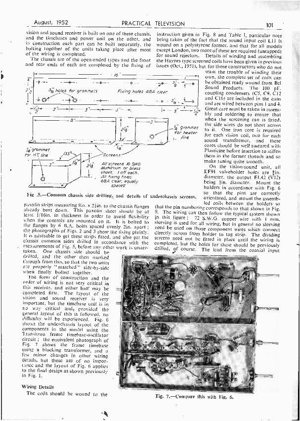
ho /es for grommets e
Fixing holes 4BA c /ear
3éß 3 "
1,
8"
'grommet for Hr line /35°
2I4
J.
A
Screens
A/1 screens /6, SWG aluminium or brass sheet. / off each. All fixing ho /es 68A clear, equally
spaced
Fig .5.- Common chassis side drilling, and details of
paxolin strips measuring 8in. x 2 1in. to the chassis flanges already bent down. This paxolin sheet should be at least 1116ín. in thickness in order to avoid flexibility when the controls are mounted on it. It is bolted to the flanges by 6 B.A. bolts spaced evenly 2in. apart ; the photographs of Figs. 2 and 3 show the fixing plainly. It is advisable to get these strips fitted, and also get the chassis common sides drilled in accordance with the measurements of Fig. 5, before any other work is under- taken. One chassis side should be drilled, and the other then marked through from this, so that the two units are properly " matched " side -by -side when finally bolted together.
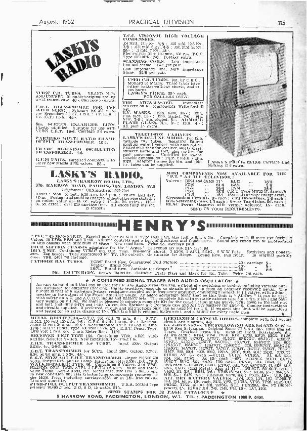
The form of construction and the order of wiring is not very critical in this receiver, and either half may be completed first. The layout of the vision and sound receiver is very important, but the timebase unit is in no way critical and, provided the general layout of this is followed, no difficulty will be experienced. Fig. 6 shows the underchassis layout of the components in the model using the Transitron frame timebase -oscillator circuit ; the equivalent photograph of Fig. 7 shows the frame timebase using a blocking transformer, and a few minor changes in other wiring details, but these are of no impor- tance and the layout of Fig. 6 applies to the final design as shown previously in Fig. 1.
Wiring Details The coils should be wound to the
grommet for heater
,line
underchassis screens.
'K#:^ 14M`k:::...
Fig. 7.- Compare this with Fig. 6.
102 PRACTICAL TELEVISION August, 1952
socket to the coupling coil (pins 1 and 3) of LI is a length of 70 ohm coaxial cable, and is clipped to the upper edge of the long central dividing screen. The outer braiding of this cable is joined to the body of the input socket by a tag under one of the fixing bolts.
Other points of particular importance are as follows :
the lead from C40 to the volume control R40 and the return to R41 are screened ; common earthing points for each stage must be used as shown in Fig. 1 and detailed in Fig. 9 ; the coil end projecting wires should not exceed some ¡in. in length below chassis ; and do not wire the damping resistances or other components across the coil pins so that the trimming hole at the base of each coil is obstructed.
Turning now to the timebase and power unit, here
; I
LI L2, L3 and other vision coils
LIO
L /2, L/3 LJ/ and and other traps sound coils when used
L /6
Fig. 8. -Coil winding details.
he wiring is not so critical, and no particular location for the leads and components is necessary. The valve positions are shown in Fig. 6, and the photographs of J=igs. 2 and 3 give the positions of the upper -chassis components. The preset controls R50 and R54 have screwdriver slots made in their spindles and they are tunable from above the chassis. The other preset controls are R64 and R65 and these are mounted on the rear paxolin strip. Valveholder holes for the valves apart from the three EF91 stages are 1¡in. diameter standard Octal. The holders should be mounted so that the pin orientation corresponds with that given in Fig. 6, where the direction of the keyways are shown. Points of importance are :
C63 and C66 have their positive holes earthy, and they should be mounted in insulating clips so that the metal cases are isolated from chassis. This is particularly impor- tant for C66 where the case is not isolated from the negative terminal. All high wattage resistances should be suspended well above the chassis, and the Thermistor CZ1 should be well clear of the shunting R81 and the chassis, as this component gets very hot in operation. The lead from the brightness control slider to the tube grid is screened and is run above chassis to the tube base.
The tagboard containing the seven
20- megohm resistances making up R77 is mounted above the chassis on the line of centres of the two chassis. The resistances are zig-
zagged on the board as shown in
Fig., 10, and, when mounted, the tags should be well clear of the chassis, especially at the positive
From PI?
E.H.T. end of the chain. R78 and C67 are also mounted on this strip. If desired, this strip may be mounted vertically between the frame transformer and VII, C67 being at the bottom end.
The connections to the line output transformer are shown in Fig. 11. The EY51 rectifier is wired directly across the upper tags, and the lead from its cathode to C65 is looped well clear of surrounding components. The inner polythene- covered lead of a piece of coaxial cable makes a suitable E.H.T. lead for this purpose. The connections to the line coils must be as shown, otherwise a narrow raster will be obtained. If the picture when first received is back to front, the connec- tions to the line coils must be reversed, not the trans- former connections.
t E.H.T. and final Anode
R77
H Tt
First Anode
Fig. 10.- Bleeder and first anode boost resistance panel details.
When the wiring of each chassis is completed, the
units may be bolted together, and the H.T. and heater wiring run through the appropriate grommets in the common wall. The video output is taken through a
grommet to the tagboard mounted on the tube rear support (see Fig. 2 and Fig. 12), and the input to the
sync separator is similarly fed through to the grid.
of V7.
To R6
C8
0
Inter vision-sound screen
H..T.
C29
0 ( From V3 6 To VI
ID
6 /
From V9 ) I To V/2 -
Fig. 9.- Layout of V2 and VS stages. This gives the general layout of all vision stages.
August, 1952 PRACTICAL TELEVISION 103
The Tube Mounting The tube is simply mounted, being supported at the
rear by the aluminium bracket shown in Fig. 13, and at the front, resting on two wooden supports, details of which will be given next month, and clamped around the mask by brass grips. The rear support is mounted centrally across the two chassis, and is placed so that it lies about 2Iin. from the rear chassis edge. In addition to
EYS /Anode
At the front, the wood blocks are screwed from below the chassis by wood screws in the position shown in Fig. 3, the distance from the chassis front edge being about lain. An ordinary rubber mask is fitted to the tube, and the brass clamps are screwed to the ends of the wood supports and grip the mask firmly around its circumference, a 6 B.A. bolt and nutlbeing used to fix the clamps together at the top. The hole in
Materia/: 16 S WG. Aluminium
I off
62
PL38 1-1.7.4 Line Anode Coils (v /5)
inner t cto c66 Outer tag to 120
Fig. 11. -Line output transformer wiring.
Position of Width control
494 clear fixing holes
4' Fig. 13. -Tube and focusing magnet support.
carrying the tagboard of Fig. 11, the focus magnet is mounted on this stand, as is also the width choke and condenser C64 with R75. The width coil locates in the }in. hole on the right of the support, and the shunting C64 -R75 are mounted on a small tagboard behind and under the focus magnet. The width plunger control is therefore accessible from the rear of the chassis.
Fig. 12.-Tagboard fitted to tube rear support. showing component
wiring.
the rear support should be packed out with a strip of felt to hold the tube neck central. When mounted, the tube should be quite firmly held, and the mask front should overhang the chassis front by about {in. A mask of the type which has a safety glass already fitted to it is best for this receiver but it is not essential.
(To be continued.)
TABLE I. -COIL WINDING DATA
Turns Coil Wire Remarks
London Wham ' Holme M.
LI 38 D.S.C. 30 D.S.C.
II 9
It 7
11 71
The aerial coupling winding is interwound at the earthy end of the main winding.
L2 38 enam. 90 90 90 L2 is close wound ; L3 spaced out by one diameter of wire. L3 30 D.S.C. 7 5 6 All other vision coils are identical.
L12 30 D.S.C. 7 6 61 Coil windings spaced out one diameter of wire. The other 113 6 5 51 sound coil is similar. Two tuning slugs are required.
LlO 38 enam. 50 50 50 Tbis coil is wound on a grommet slipped on a I -watt re- sistance, value á to I M D. The ends are connected to the resistance leads.
L11 22 tinned copper
8 6 7 For LII the winding is centre -tapped. For sound -trap use, no tap is required. The former is polystyrene with iron slug tuning.
L16 38 enam. - i - - Close wound to fill former to within tin. from each end, approx. length tin. Not critical. No core is used here.
N B. -IC .Irk o Shotts constructors use windings as for Birmingham. Wenvoe constructors use Birmingham windings less 4.turn.
p r
w 104
Some
1
PRACTICAL TELEVISION
Queries Answered, relating to- THE
August, 1952
TELEVISION REC: P`Ì.
SOME READERS' DIFFICULTIES OVERCOME
THE Argus was designed with two main objects in view : they were to produce a complete, yet inexpensive, televisor and to give plans so that
construction could be undertaken by the novice. Our correspondence has shown that both objectives have been reached, and the series of articles has brought television to many who could not afford a commercial televisor, and yet who did not have the technical knowledge which would enable them to build directly from theoretical circuits.
Now it has been said that it is very easy to wire up a circuit from a blue -print, but the difficulties arise when the power is switched on, and snags begin to crop up. It is at this point where past experience comes to the aid of the more advanced worker, but the constructor who is building a televisor for the first time is quite often puzzled by queer " faults " which are actually part and parcel of television phenomena.
We have found that queries on the Argus have fallen into three main categories : the first is in regard to the phenomena mentioned above, the second is about the liberties which can be taken with published designs, so that components which are on fiand can be utilised, and the third group is timebase troubles.
The Raster Dealing with the first group, one of the most frequent
queries is with regard to the appearance of the raster. If no signal is being injected into the tube circuit (i.e., with the Contrast control at zero or with V13 removed) then the normal appearance of the raster is as shown in Fig. 1. The line oscillator V15 and its associated amplifier valve V16 produce a line across the tube face ;
Frame flyback
lines
Fig. 1.- Normal appearance of a raster without picture detail.
the backward stroke of the beam, or " flyback " to give it its correct term, moves so rapidly that it is scarcely visible. The frame flyback is, however, clearly visible, but it does not travel in a straight line from the bottom to the top of the raster but zig -zags across the tube.
It will be found that with electrostatic tubes such as the VCR97 the flyback lines are about :A -¡in. apart.
When the televisor is first switched on. the raster will probably be found to consist of a fuzzy oblong shape. Operation of the Focus control will enable the lines to
be clearly discerned but the actual size of the raster will
be reduced. It must be remembered, therefore, that the operation of the Focus control will affect the overall dimensions of the raster.
It is quite probable that the frame flyback lines move up and down, the speed being varied by operation of the Frame Hold control. Sometimes, if the frame frequency is very low, the whole raster will jump up and down.
The Frame Hold control actually controls the frequency of the oscillations of the frame oscillator. In practice it is used so as to bring the natural frequency of the frame timebase close to that of the transmitted signal, until the synchronising pulse from the signal takes over, and controls the actual period of each frame stroke.
If the frame frequency is very low the lines of, the raster will be spaced very wide apart.
Another phenomenon is a high -pitched whistle which emanates from the timebase, and which can be varied in pitch by the operation of the Line Hold control. It will be found that this whistle can come from the line,
oscillator valve itself ; some valves are more prone to it than others. As the Line Hold control is varied it
be found that the whistle disappears : this is because it has reached a pitch which is beyond the range of the human ear to resolve.
Tubes VCR97's have been made by different manufacturers
and vary a little in their characteristics. Table I gives
the details of two types of VCR97. The constructor should take care to purchase a tube which is guaranteed to give full picture size ; some tubes have deflecting . plates so positioned that cut -off occurs and neither full
width nor full height can be obtained. Without any signal being injected into the tube,, it
should be possible to black -out the raster completely.l y
reducing the Brilliance control. Further details on this
August, 1952 PRACTICAL
point will be given later in the article. It is important to remember that the raster and the picture are, to all intents and purposes, separate items. The picture is not produced by modulating the raster with the picture signal. When receiving the picture the Brilliance control should be reduced until the raster completely disappears from the tube ; the tube face should be blank, when the Contrast control is at zero. It should only just be blank, as this is the most sensitive position.
When the Contrast control is advanced the picture signal should produce its own " raster." When the picture has been correctly locked by the Line and Frame Hold controls, then the flyback lines from the frame circuit will not be visible ; the picture itself blacks out the flyback. During the frame flyback the synchronising pulse applies a heavy negative potential to the grid of the CRT so that the cathode -ray beam is prevented from reaching the screen.
Adjusting the Controls The correct operating conditions to receive the picture
are as follows :
The Line and Frame Hold controls should be turned in any direction until they reach the limit of their travel. With the raster just blacked out, the Contrast control should be advanced until a pattern appears on the screen, the average brilliance of which is more or less equal to the previous brilliance of the raster. The pattern may be fairly steady or it may be moving -it doesn't matter which condition obtains.
The Line Hold control should now be turned slowly until the pattern changes into a number of broad hori- zontal lines which may be moving up and /or down, then as the control is further advanced the lines will commence to move at an angle until they become almost upright, and at this point the picture will be found to be resolving. The control is then adjusted steadily until the picture is completely resolved. The actual point of complete resolution is rather critical.
If the control is turned beyond this point the picture will collapse into lines again.
Should you find that, as you commence to turn the Line Hold control, multiple pictures appear it simply means that the frequency of the line oscillator is a multiple of the line frequency, and you should continue turning the control until the correct single picture is resolved. As a matter of interest you will quite often find that in travelling from one limit of the control to the other, double, treble and quadruple pictures can be received.
If the picture tends to slip upwards then it can be locked by operation of the Frame Hold control. If the Frame Hold control is at a point very far removed from the frame frequency, the unresolved pattern will flicker rapidly in a vertical direction. If you find that
Table / G.E.C. (VCR97)
Heater V = 4v. Heater I = / /A. Vat , = 2500 Max. Va2 = Va3xOs'75mean Vai z 5000 max. /000min Vg ' _ (Vat x 0'04)max
Mu /lard (VCR 97) Heater V - 4v. Heater I = rO A. Val Va3 2500V. Va2 260 to 450V. v9 _ / to /00v
Fig. 2 (right). - Appearance of the flyback lines with correct and one form of incorrect interlacing. On the left is a table of \'CR97 characteris-
tics.
TELEVISION 105 ' this is the case when you first turn up the Contrast control, then you will not be able to resolve the picture with the Line Hold control. The correct thing to do is to adjust the Frame Hold control first, until the pattern is fairly steady.
If you have two or more complete pictures one above the other, or if the picture has incorrectly locked so that the top half appears at the bottom and vice versa, then the Frame Hold control must be further adjusted, until a single complete picture is obtained.
Interlacing In most cases interlacing can be checked by advancing
the Brilliance control while the picture is on, until the flyback lines appear. (By " interlacing " is meant the alternate scanning of odd numbered and even numbered lines, which is done at the. transmitter.) The lines will not be complete across the whole of the tube, those at the bottom appearing in part. Under correct interlace conditions the lines should be evenly spaced, and not " paired." Adjustment of the Frame Hold control will ensure correct interlace, and it will be found that the correct position is a littlo critical. In the Argus, in spite of the simple circuits employed, it will be found that the interlacing is quite good, and a steady picture results. Fig. 2(a) shows lines " pairing."
To obtain the best relation in tonal values of the picture, the Contrast control and Brilliance control should be adjusted together so that the correct tones of white, neutral, grey and black appear on the tuning -in signal. The best method is to reduce the Brilliance control for the blacks, and to advance the Contrast control for the overall brightness of the picture. Fig. 3 shows the tuning -in signal.
Where the signal is weak, or where difficulty is being experienced in getting the vision signal, it is possible to advance the Brilliance control a little so that the raster appears very faint on the screen. The picture will then appear superimposed on the raster.
(a)
"Frame flyback ! lines "pairing' i They should be i as /n (b)
Frame flyback fines as they should appear
(b) Note: (a) and (b) are the conditions obtained when the brilliance control is advanced while receiving e
picture
106 PRACTICAL TELEVISION August; 1957 '
The Sound Receiver There should not be much difficulty with the sound
receiver, the only points to bear in mind here are that the trimmers TI, 2 and 3 (0 -30 pF) should be used for the tuning, the iron cores of the coils being used as
verniers for fine tuning. It should be noted when taking voltage checks that
there will be very little voltage on the second anode of V9 due to the high resistance of R23.
L2 is rather critical where the signal is on the weak
side ; it can be made less critical by connecting a 4.7k
across it. Remember that the tuning of this
coil and of LI affects both sound and vision.
Vision Receiver The blueprint shows no rejector coils for Alexandra
Palace. These are not required and can be omitted together with their associated con- densers C9, 10, 17, 18.
1f, when listening for the vision signal, it is found that the Contrast control goes " plop " at a certain adjustment, it means that the vision receiver is breaking into oscillation at this point. It can be cured by correctly tuning the coils, and checking the decoupling circuits.
The best method of aligning the receiver is by use of Test Card " C," which is radiated every morning of the week except Sunday. Full details of the Test Card were given in the June, 1951, issue of P.T.
It will be found that the quality of the picture signal can be affected by the sync. pulse. If too high a line sync. pulse is injected into the line oscillator then the edges of the picture will become very ragged, and /or the picture ,will appear very smeary and watery. The correct amplitude of sync. pulse is obtained by adjusting C48.
When a pre -amplifier is used and the contrast is at maximum then the background of the picture becomes affected, and it appears as though the scene is being televised in a snowstorm. This " snow " is the visual
representation of valve hiss. The only method of oyercoming it is to improve the aerial system.
Where a good signal is received, over -advancement of the Contrast control will produce a negative picture with the whites black and the blacks white -as in a
photographic negative.
Tracing Troubles Firstly, let us get a clear idea of what can be done. (a) The vision receiver can be made to work inde-
pendently of any of the rest of the televisor (with excep-
tion, of course, of power supplies). It is not necessary
to have the timebase working in order to receive the
vision signal ; it is, of course, necessary to have the
timebase and CRT network functioning to receive a
picture, but the vision signal can be tuned in and the
vision receiver adjusted by connecting a pair of ear-
phones across R33 or in series with V6 and R17. It
will sound like a very rough hum, which you can verify
is the picture signal by disconnecting the aerial. (b) The sound receiver will work without the rest of
;he receiver. It should be remembered that the tuning
of the sound receiver is affected by LI and L2. VI in
the vision receiver must therefore be functioning, though the remainder of the vision receiver can be disconnected.
(c) The timebase can be made to work independently of the rest of the circuit. It is not necessary to have the vision receiver working to produce a raster. It is necessary, of course, to have the E.H.T. and C.R.T. network functioning before a raster can be obtained.
(d) The C.R.T. network can be made to function independently of the timebase providing that the timebase H.T. is available at the VR8¡9 potentiometer network.
If the timebase is not functioning, a spot will be seen
on the tube ; the Brilliance control should be adjusted so that the spot is not too brilliant or you will burn a hole in the screen. The spot can be focused, widening out to almost l¡in. in diameter from a mere pin -point, by
operation of Focus and Brilliance controls. The spot
Fig. 3.- Details of the tuning signal.
can be shifted up or down and left or right by the shift controls.
In each case mentioned above the power pack must not be left too lightly loaded. The H.T. should not be
disconnected from more than one unit at any onetime. Do not run the E.H.T. transformer without the
rectifier and bleeder network in circuit. Peak voltages are liable to develop and cause a breakdown in the
transformer. If it is desired to test the circuit without the
E.H.T. supply, then disconnect the supply at R65 but leave the bleeder network VR9, R67, etc., in circuit. Alternatively, disconnect the primary of the E.H.T. transformer.
USING THE UNIT TO BUILD TWO A.C./D.C. PRE- AMPLIFIERS, AND TWO SUPERHET
CONVERTERS -THIS MONTH WE DESCRIBE THE REMAINING UNITS
(Continued from July issue)
T HE SP6I is quite a good valve, but its performance tends to fall off at the higher frequencies. The RF24 can be made to give a greater output than
that obtained by the modifications given in last month's issue, and although the further modifications are fairly simple a lot more work is involved and extra components will be required.
The new circuit diagram is shown in Fig. 8, and it will be seen that the main alteration consists of using EF54's (VR136) instead of the SP6I's.
The unit should be altered on the lines suggested previously, but the two coils LI and L2 with their associated tuning condensers, should be removed and replaced by new coils wound on Alladin coil fornis 3,8in. in diameter.
The two valveholders in VI and V2 positions must be replaced by B9G valveholders. The change -over of the wiring to the new valveholders is effected as given belonn :- I.st valve Wire going to pin 1 (SP61) now goes to pin 1 (EF54).
2 >, ,> 4 3 2
It 4 19 3 5 is disconnected and earthed. 6 8 now goes to pin 9 (EF54).
The EF54 pins 4, 5, 7 and 8 are joined together and the cathode decoupling increased by the addition of another 500 pF condenser. 2nd calve Wire going to pin 1 (SP6I) now goes to pin I (EF54).
2 9, 4 , 3 2
97 4 3 99
5 is disconnected and earthed.
8 now goes to pin 9 (EF54). The EF54 pins 4, 5, 7 and 8 are joined together and the cathode decoupling condenser is increased by an additional 500 pF condenser in parallel with it. The EF54 pin 6 goes'tö L2 viá a short length of coaxial cable, the otter 'sheath of which is earthed at both ends.
The coils LI and L2 are wound on tin. coil formers
with iron cores, and are mounted in the position shown in Fig. 9. The chassis must be drilled so that the cores can be easily adjusted from the outside. The small coil formers are used so as to keep the coils clear of the chassis.
LI is wound in accordance with the data given in Table III. The secondary is wound on first, starting from the bottom and winding in a clockwise direction. The primary coil is wound in a similar manner, on top of the secondary, using insulated wire.
The earthy ends of both primary and secondary windings are connected to the chassis by looping under the coil - retaining bolt. The other end of the secondary of LI goes to the grid of VI (pin 6). The other end of the primary goes to the aerial socket by means of a short length of 80 D coaxial cable which is earthed at both ends.
L2 is wound in accordance with the data given in Table III, and is mounted in the position shown in Fig. 9. The earthy end of L2 is earthed under the coil retaining bolt, and the other end is connected to C6. The other side of C6 is, of course, connected to the junction of R6 and R7.
Coaxial cable is used to connect the top of L2 (i.e.. at the junction of L2 and C6) to pin Y of V2. The outer sheath of the coaxial cable should be earthed at both ends.
Components The component numbers given in Fig. 8 (R2 .., etc.)
are the same as in Fig. 1, the items which are not used in the new modification being omitted. See list on page 108.
As the EF54's require only 0.3 amp for the heaters, the power supply circuit must be altered. It is best to dispense with the VR65 used as a rectifier and replace it with a small selenium rectifier capable of supplying 30 mA at 250 v. A barretter, type Philips CIC, can be used as a voltage dropper for the heaters. The modified power supply is shown in Fig. 8.
The modified unit now forms a powerful A.C. 'D.C. pre -amp. which is self- contained. The precautions given in the previous modification regarding the " live chassis should be observed. If desired, the barretter can be replaced with a small L.T. transformer, thus makina the unit purely A.C. operated.
108 PRACTICAL TELEVISInN August, 1952
TABLE III
Station LI Primary L1 Secondary L2
Wenvoe .. .. 14 74 74
Sutton C... .. lt} 8 8
Kirk o' Shotts 2 9 9
Holme Moss .. 2 10 10
Alexandra P. .. 21 11 10
in. coil formers, 22 s.w.g. wire ; primaries, insulated wire.
Front of
Chassis
Fig. 9.- Mounting position for 12.
A Superhet Converter for the Experimenter for Use with the R1355 The next modification is to use the RF24 unit as it
was originally intended to be used, but covering the TV frequency range.
As new TV stations are opened the number of fringe viewers becomes more, not less, because more areas are
brought within the range of fringe viewing. There are not a few pioneers among the readers of
this journal, and correspondence seems to indicate that some inexpensive unit is required so that the experimenter can determine the strength of reception in his area, before venturing into the expenditure involved in constructing a complete televisor.
The RF24 can be very easily and cheaply adapted
for this need. The idea is to modify it so that it acts as a superhet converter, providing the TV signal at an I.F. of 7 Mc/s. This can be injected into a broadcast receiver which is tuned to 7 Mc's.
An inexpensive aerial can be constructed and erected on a long ladder or something similar. Details for the making of such an aerial, costing only a few shillings, have been given in previous issues of PRACTICAL
Ti 0.30pF T2 0.30pF Cl (see coil data) C2.001F C3 300pF C4 .001 tiF C5 300pF C6 100pF C7 (see coil data) RI 47 0 R6 4.7K S3
R2 100 0 R7 22 !3
R3 10!3 R8 47 D. R4 10K !3 R9 2.2K S3
R5 221.0 RIO 2.2IC0
1
R11 1,0001 (2 w.) R12 See text R13 R14 33 D.
The modifications outlined in the following paragraphs will also make the unit suitable for the reception of sound on a broadcast receiver, and it can then be used solely as a sound receiver in its own right.
The alterations required follow closely the methods given previously. The circuit is shown in Fig. 10.
1. Remove the switch. 2. Remove all conponents
in compartment la, except one tuning condenser and the coil. (See Fig. 2.)
3. Remove all components in compartment 2a, except one tuning condenser and the coil.
4. Remove all components in compartment 3a except one
C14 tuning condenser and the coil. 5. Modify the coil in com-
partment la in accordance with the data given in Table I. (LI.)
6. Modify the coil in com- partment 2a as per the data in Table I. (L2.)
7. Modify the coil in com- partment 3a in accordance with the data given in Table IV.
It is important to keep all
T1/ I
R2 Condensers
and y are 500pFk
Fig. 8.- Circuit of the two-stage pre -amplifier.
August, 1952 PRACTICAL TELEVISION 109
wires short and rigid so as to avoid frequency drift. If it is found necessary to remove the connecting bar from the coil to the trimmers in compartment 3a, when removing the switch, it should be replaced.
A power pack must be constructed and can either form a separate unit or can be bolted on to the back of the RF24 unit. Fig. 11 gives the circuit of a suitable power pack.
No other modifications are necessary, but if it is desired to operate the unit as an A.C. /D.C. receiver,a power unit can be built as shown in Fig. 12. The heaters of the valves will have to be wired in series.
Having completed the alterations the output on the Jones plug (the coaxial cable tag), should be connected to the input of the broadcast receiver. The connection should be made with 80 9 coaxial cable and the outer sheath should be earthed at both ends, via a 500 pF condenser.
Set the tuning scale o the broadcast receiver to a quiet spot on the dial at about 7.5 Mc /s. Tune the oscillator in the RF24 unit (the last coil in compart- ment 3c), for maximum noise. Now tune the mixer con- denser for maximum noise and follow this with tuning the first RF condenser for maximum noise.
The next step is to connect an aerial to the input socket of the RF unit, using an aerial of the type in general use in your own locality. For the fringe viewer an aerial with one or more directors and a reflector should be used, erected as high as possible. It should now be possible to tune in the sound channel by means of the oscillator condenser, but do not forget to make certain that a programme is being radiated.
The mixer and RF stages should be tuned for maximum volume.
When the signal has been correctly tuned, the trimmers should be locked in position with a spot of wax.
!U
3OOpF 22Kí]
It is important that ,the lead from the RF unit to the receiver is well screened. Do 'not have long ends it the extremities of the coaxial cable or the receiver will pick up strong signals at the intermediate frequency.
600 0 50 W.
Fig. 12.- Modified circuit for A.C./D.C. use.
TABLE
Station Coil turns Coil tap Condenser
Wenvoe .. .. 21 f Nil Sutton C. .. .. 21 I 15pF Kirk o' Shotts .. 21 } 20+ 15pF Holme Moss .. 3 1 15pF Alexandra P. 3 11 20+ 10pF
(If you have difficulty in getting the correct IF, try adding a 10 pF condenser, in addition to the one quoted above.)
The modified unit, without the power pack, can be used in the R1355, with good results. There appears to be a dearth of R26 and R27 units which cover the higher TV channels.
2Kf) 300pF
Output 2 .2Kf)
300 pF
3.3.41
/00 pF /00 Kf) /0 0°1
50 Kf1 pF
25Kf)
470
HTf
47f) 50pF
00 /pF T300
PF
T300
PF Fig. 10.- Circuit of a superhet converter.
00
TnF
A
110 PRACTICAL TELEVISION August, 1952
A Long Range Superhet Converter The R1355 I.F. strip is one of the most powerful
of the ex- Government strips on the market. It has six stages of 1.F. amplification using five SP6I's and is
eminently suitable for long -range reception. When used in conjunction with the RF26 or 27, the signal -getting properties are remarkable.
Unfortunately there seems to be very few RF26 or 27 units about, and although the RF24 unit can be -used when modified as explained in the previous para- graphs, the RF26 or 27 will pull in a signal which the RF24 cannot touch.
-However, it is not too difficult to convert the RF24 into a unit which is almost as good as the RF27, by using EF54 valves in lieu of the SP6I's in the mixer and RF stages.
The circuit should be modified as shown in Fig. 8, and the alterations to the wiring in compartments la and 2a can be made as already given. Compartment 3a remains as it is and the existing coil which is in compartment 2b should remain in situ, the output wires being connected to the new mixer stage, in the same way that they were connected to the SP6I.
The power supply section of Fig. 8, should not be used, nor should the heater wiring of the unit be touched.
If it is desired to operate the unit as described in the previous section, for experimental purposes, the power pack data given in that section can be used, but the 6000 voltage droppers can be replaced with a Philips CIC barretter.
The oscillator coil should be modified as given in
Table IV, and in all respects the oscillator circuit should remain as explained in the previous section. ' Better results can be obtained by using a VR137 (EC52) as the oscillator valve instead of the SP6I. The required circuit is given in Fig. 13. It will be noted that
the method of injection of the oscillator frequency is modified.
(Mixer) V2
I11112
20F
roof) 100 KO
500
4
Coax ,........, L
LTt
Fig. 13.- Modified oscillator stage. L3 consists of 5 turns 22 s.w.g. on ¡in. former with iron slug for channels 1 and 2; no slug for channel 3 and brass slug
for channels 4 and 5.
Alignment details are the same as those given previously.
Miniature TV R.ecciVCr "'HIS MASTER'S VOICE " produced recently a
11 small lin. tube television receiver for demonstra- tion purposes, primarily to emphasise the large pictures given by the 15ín. and 21ín. receivers manufactured by
the company. Subsequently "His Master's Voice"
approached Her Majesty Queen Mary with a view to providing a similar model for Queen Mary's Doll's House at Windsor Castle.
The Gramophone Co. Ltd. are now privileged to announce that H.M. Queen Mary has been pleased to accept a specially- constructed miniature model for this 'purpose.
Complete in every external deta;l the - model for the doll's house is an exact
1/12th scale replica of the well -known " His Master's Voice " 15in. console receiver Model 1806.
This miniature model was handed personally to Her Majesty at Marl- borough House by Mr. George H, Watson of the Gramophone Co. Ltd..
,,.on May 28th. The . Royal Doll's House will thus
be keeping apace with modern developments And the small television set ,will take its place with the scale model gramophone and radio receiver which were previously presented by the company.
August, 1952 PRACTICAL TELEVISION
INTERNATIONAL TELEVISION TO -DAY
By CECIL MADDEN, Assistant to Controller, BBC Television Programmes
ON August 15th a new television transmitter opens at Wenvoe to serve Wales and the West of England. Then 75 per cent. of Britain will be able to see
pictures in the home and join the vast million- and -a -half licence -holding fafnilies distinguished by the now familiar television aerial.
Television is expensive in all its aspects, but despite every financial handicap in the world's forward march towards technical progress, the position of international television is very fascinating to watch as it grows steadily more earnest and purposeful. Let us study the European position first as it is the nearest.
Last summer Calais was linked to London for a day ;
last month Paris was linked to England and Scotland for a week. This direction is significant as television's tentacles reach out always a little farther. In Europe to -day, France, Denmark, Holland and Italy have already started services, in greater or lesser degree. Spain, Switzerland and Belgium are at the estimate stage. Germany is likewise discussing transmitters. Russia is still something of an unknown quantity. Recent news is that there are plans for television in Turkey.
France Not all of France is served as yet by Radio Diffusion
Française. So far Paris is only joined to Lille in the industrial north. Italy, the latest continental entrant, has new studios and transmitters at Turin and Milan, likewise their industrial north, but Radio Italiana have elaborate plans to open in Rome together with many other cities in 1954. This will be the opportunity for British apparatus and equipment. But it must be remembered that Italy has many special problems in developing television ; there are great riches and much poverty, with huge sprawling distances to cover, many mountainous, and stretching down as far as Sicily. Then Italy has a sunny disposition as well as climate, which encourages promenading out of doors, the very enemy of television, whereas our invariably cold and wet weather drives us in to our TV and teacups. The Italians have a great heritage of art and music, so that when the time comes for more international programme exchanges,- whether live or recorded, Italy has much to offer.
Italy Milan's television transmitter nestles inside an old
pre -war tower in the middle of its park. Turin TV programmes are carried up a high mountain (Trivero) and by an engineering feat are passed on to join the Milan output. Both opened simultaneously in April
this year for the Milan Fair. It is interesting to recall that the first London transmitter at " Ally Pally " opened for an exhibition. too, in August, 1936.
Sunday Plays It is fair to say that Britain's television is based on
plays on Sunday night -dramatic material in various forms, whether classical, comedy or drama, a decision I myself made very deliberately when programme organiser in charge of the production of the service back in 1938. This has undoubtedly had far -reaching consequences on the nation's life to -day in making the entire country play minded (may I emphasise that I do not mean theatre minded since no playhouse is involved) on the key viewing night of the week, when the whole family can be together. I believe the Sunday play to be my greatest contribution to British television and I am particularly proud of it. Even in 1937 I had seen to it that viewers were already accustomed to full -length plays on four nights of the week, with first showings in the afternoon. It became a question only of changing the days to Tuesdays, Thursdays, and even Saturdays (now these are sometimes serials). This has gone on ever since. On any night it can mean an audience of five to 10 million people for a dramatist. We do not lack actors and actresses : Britain has a wealth of acting talent, and dramatic schools pouring out newcomers regularly. Italy has many famous playwrights and brilliant film directors, but withal no such reservoir of professional stage folk, since all it has are occupied in film and theatre work. So its TV planners will pre- sumably have to look in another direction for its main and staple programme fare, which is more likely to be news telecasting in differing ways.
The Dominions The Dominions have not appeared in the world scene
as yet, but they are not far behind. True, for the time being, Australia has postponed the date for television indefinitely in favour of first things first, but Canada is opening in the east this year. Parts of Canada have, of course, been able to see American television programmes for some time.
U.S.A. Moving on into the New World the commercial
and sustaining television programmes of the U.S.A. have been much publicised and lately discussed in the press and elsewhere. Some stations pour out programmes all day and night. but what is less known is that two thirds of the United States have still only one outlet, a " captive
112 PRACTICAL
audience," as it is called there, and thus are in no different state from the United Kingdom viewer. The remaining third has choice, in fact, in New York City a viewer has the choice of six channels.
Latin America Farther south we come to Mexico, Cuba, Brazil and
Argentina with already flourishing daily schedules,. Mexico and Cuba can exchange programmes since both are Spanish- speaking. Brazil is so enormous there is room for a great deal of television in its coastal towns alone. So in Latin -America the television race has well and truly begun. All the republics are interested -which country will get in next ? Uruguay, Ecuador, Venezuela or Bolivia ? And what gear will be used', There is room for interesting competition, taking Into account national tendencies, temperament, climates. resources and the remaining imponderables.
The Lighter Side But there is another, lighter side to the general picture.
Television presents some amusing speculations on the new civilisation of the ether. It is presumed that pictures through the air can penetrate even Iron Curtains. Given the possibility of distant choice a Frenchman tunes into London and what does he see ? " Café Continental," full of his own favourite artistes. What does the Italia. find ? Perhaps a Pirandello play in English or an Italian film with sub -titles. A Spaniard looks to London and sees Flamenco dancing. Madame Ashkenazi might tune in to A pantomime on skates or the brothers Karamazov to a blonde announcer grappling with a gorilla. No longer will the three wistful Tchekov sisters look to Moscow as the Mecca of their hopes and aspirations -one will want to join the Twelve Toppers, another to become a Top Ten mannequin, the third in a low -cut V -neck evening dress will be quizzing in a panel show which is really only a modernised version of a children's parlour game. Yes, coaxial or air link travel will set curious new standards of behaviour as well as taste.
Speaking from experience of the . now not so new medium of television,
as the producer of the very first high - definition programme in the world from the Alexandra Palace studios in
August, 1936, and with continuous acquaintance of its operation since, I
believe firmly in the future of both regional and international television. .ft will change our own lives and possibly everyone else's as well. Let us welcome the west with its agricul- ture, Wales with its mines and song, Scotland with its industry, dramatic scenery and its pipers. All these obvious pictorial riches will add to "selling" Britain to Britain, a desirable result in these days of restricted
'foreign travel. But this international armchair magic carpet will be some- thing else besides ; for the Lancashire lad whose only holiday has been Blackpool, the vista is endless, a
vicarious view of Mi- Careme on the
TELEVISION August, 1952
Riviera, Holy Week in Rome, ticker tape on Broadway, Folies- Bergère in Paris, Toros in Seville, Mardi -Gras in New Orleans, fishing off Florida, Copacabana Beach at Rio, Gauchos on the Pampas, ski- jumping in Norway. It is quite a novel pastime imagining programmes for other countries and continents.
Our Royal Family The world, on the other hand, will want to sec us in our
islands, our Royal Family, our ancient traditions, our " London Town," Trooping the Colour, Changing of the Guard at Buckingham Palace and St. James's, Edinburgh Castle, Blackpool Tower -all manifestations of - our unique way of life whikh means so much to us and is so genuinely envied abroad.
A World Leveller So it is perhaps not impossible to hope that when we
can look into the homes of Marianne and Teresa and Fulvia and Gretchen and Ingrid and Katie and Sadie and Aischa, and their husbands, Alphonse and Luis and Guido and Hans and Henrik and Karl and Hiram and Ali, look into ours and realise that fundamentally we are much the same ; that cooking, babies and recreation occur everywhere- tbo.ph varied by customs and con- ditions -then as a medium for good television .may. indeed, come into its own both as a world leveller and a powerful instrument on the side of humanity.
Cecil Madden talks to Franco Eariga>ez, Italian television producer, in one of the studios at Lime Grove.
August, 1952 PRACTICAL TELEVISION 113
STRAYS AND LOSSES THE IMPORTANCE OF LAYOUT AND WIRING IN THE MODERN RECEIVER
By W. J. Delaney (G2FMY)
MANY constructors spend considerable time in studying articles on television theory, and when they eventually build a receiver, incorporating
those principles which they think desirable, are dis- appointed to find that the equipment does not measure up to their expectations. In most cases this is on account of the fact that they have failed to watch one point which is seldom mentioned in theoretical articles- - namely strays or losses. These are encountered mainly in the layout and wiring rather than in the theoretical considerations, and accordingly have not received the prominence they deserve. A simple example will serve to show what is meant by this title. Take the grid circuit of the first stage of a simple television receiver, either straight or superhet. It will consist in the main of a tuning coil with adjustable core, in all probability a damping resistor across it, and that is all (Fig.1). The usual tuning circuit consists of an inductance and capacity in parallel, and the principal tuning in the circuit just referred to is effected by the stray capacities, indicated in Fig. 1 'by the dotted condenser Cs. It should be obvious from this illustration that, in view of the very small inductance which is used at television frequencies, the magnitude of Cs.can have a very marked effect on the minimum range to which the circuit will tune. Most designers base their coil data on average stray capacities not exceeding 20 pF and as an indication of the effect of a small capacity it may be mentioned that a 0.7 ldH coil such as might be employed in a London receiver will tune to 45 Mc /s (the Vision frequency) with a parallel (stray) capacity of about 18 pF, whilst if this capacity is increased by only 4 pF it will tune to about 40 Mc /s or below the Sound frequency. These figurés ignore, of course, the effects of any iron or brass core which may, be included in the coil.
R.F. Circuits The stray capacities in an R.F. stage are introduced
Fig. 1 (above). -Stray capacities (Cs) in an R.F. circuit will affect the tuning range. Fig. 2 (right).- Strays in a video stage will affect picture
quality.
T Cp .+r. Cs
mainly by the wiring, in view of the very few com- ponents which are employed. There is. of course, a difference between a ceramic and a paxolin valve -holder, and slight differences are also introduced by screening cans over coils and also between a metallised and a non - metallised valve. These facts should, therefore, be borne in mind, especially if one is taking a published circuit and modifying it for individual use, or changing a published layout design. In some circuits rejectors and other coils may be found associated with pre -set con- densers of about 40 pF and in these, of course, slight additional modifications of stray capacities will not have such a marked effect as the adjustment of the pre- set will enable the change to be covered. Where, however, there is no such condenser care must be taken to try and keep within the stray capacities which have been allowed for by the designer.
Sync Circuit There is one other part of a modern circuit where
stray capacities can seriously affect performance, and
Fig. 3.- Excessive stray capacities in the grid circuit of a sync separator stage may result in lack of control in the time bases. C'S =pi
that is in the coupling between the video stage and th sync separator. In the video stage there is already large effective parallel capacity in the power supp1 . and this will produce resonance with any correction chokes which are included in the stage, and in several receivers which have been examined by the writer to find the cause of serious outlining (or black- after -white) it has been found to be due entirely to the stray capacities in the video stage. The correction chokes, again; have no intentional capacities connected to them, and in cases where black- after -white is found to he troublesome a temporary check may be made by short- circuiting any such chokes when it will be found, provided that the tuning circuits are not at fault, that the trouble will be removed, and then, if such chokes are thought desirable. some attempts should be made to reduce the associated stray capacities. The chokes should be mounted well clear of a metal chassis ; several connections should not be made to a single point, and the chokes should be made strictly to specification. In some output circuits it may be found that at the video anode there are shown in the theoretical diagram, an anode load resisto-. a
114 PRACTICAL TELEVISION August, 1952
feed choke to a potentiometer across H.T. feeding the C.R. tube, as well as a connection to the sync separator stage.. All these leads should not be hunched and taken to a single point, for instance, the video anode socket connection. It will be found preferable to take a single wire from the latter point to, say, one of the correction chokes, and then along this lead to take off the various incidehtal connections. Similarly, the lead to the sync separator stage will in most cases be taken through a condenser (and perhaps a resistor) to the separator stage, and this also should have a very low capacity not only in the interests of picture quality in the video 'stage, but also to avoid losses in the sync pulses. The condenser should, therefore, preferably be of the card- board case or mica type (rather than a metal -cased variety) and should not be placed close to the chassis. It should be supported in the wiring or mounted on a tag strip or component mounting panel in such a manner that only the end is presented to the metal surface of the chassis and the associated wiring should not run parallel to an earthed wire or surface.
Linearity Stray capacities in some time hase circuits may seriously
affect linearity, and where difficulty is experienced in - obtaining a linear result from a published design attention should be paid to any parallel stray capacity effects which might exist and call for a modification of con- densers which are fitted, or the removal of the excessive strays. In addition to the point mentioned above there is one other associated with capacities and that is leakage in a component such as a paper condenser. These do develop leakage in the course of time and also as a result of overloading, and in quite a number of circuits any leakage which exists may seriously affect the working of the circuit. For instance a leaky coupling condenser may result in a positive potential being applied to a valve grid and prevent the valve from functioning properly. Therefore, any condenser which acts as an isolating medium (rather than one which has a resistor in parallel with it) should be chosen to have as low a power factor as possible and old used capacitors should not be employed in such circuits.
Valve News DESIGNED to meet the demand for advance or more
complete information on Brimar valves, the new Brimar valve application report service has so far covered the following types :
A report on a time base for the CI4BM rectangular wide angle C.R. tube has also been published.
Extra copies of individual reports can be obtained for 2s. 6d., or 5s. each, depending on the type, and these are stitched into a protective grey cardboard stiffener.
New American Valves
The Sylvana Company of America announce two new
valves, 6BX7GT and 6111/2.
The 6BX7GT is a high perveance double- triode de-
signed for vertical deflection and oscillator service in television receivers.
The 6BX7GT is particularly well suited for reduction of vertical distortion in television receivers due to low plate supply voltage.
-The new tube is mou'ited in a T -9 bulb and is supplied with a short intermediate shell octal base with 8BD hase
connections. It may be mounted in any position. The tube is 1 sein. in diameter, 3 din long, and is 21in. high when seated.
Electrical characteristics of the 6BX7GT include :
Heater volts .. .. .. 6.3 Heater current, amperes .. .. 1.5 Plate volts (each section) .. ' .. 250.0 Plate current, mA (each section) .. 42.0 Plate resistance, ohms .. .. .. 1300.0 Transconductance, micromhos .. .. 7600.0 Amplification factor .. 10.0 Types 6111 and 6112 are sub -miniature double triodes. The new triodes were designed for use at relatively high
ambient temperatures where long life ana stable per- formance are required under severe shock and vibration
conditions in compact. lightweight equipment. Both of these tubes are suitable for use at frequencies ranging up into the U.H.F. region.
Type 6111 is a medium -mu double triode in a T -3 envelope, with characteristics similar to those of type 6SN7GT and may be used for similar applications within the 6111's ratings. Characteristics of the new sub- miniature 6111 include :
Filament, volts ,. 6.3 Filament, current, mA .. .. .. 300.0 Plate, volts (maximum) .. ... .. 150.0 Plate current, mA (maximum) .. .. 22.0 Plate dissipation, watts (maximum) .. 1.1 Transconductance, micromhos .. . ,. 5000.0 Amplification factor .. .. .. .. 20.0 Type 6112 is a high -mu double triode in a T -3 envelope
with characteristics similar to those of type 6S1.7GT and may be used fer similar applications within the 6112's ratings. Characteristics of the new subminiature 6112 include :
Wenvoe Tests THE BBC are making daily test transmissions on
medium power from the new television transmitting station at Wenvoe, in readiness for the opening -of the station on August 15th. The tests normally take place each week -day, apart from the Bank Holiday week -end, between 11 a.m. and 12 noon and between 3 p.m. and 4 p.m., but they are subject to interruption and alterations in timing in accordance with engineering requirements.
The morning transmissions consist either of demon- stration film or of still patterns, and the afternoon trans- missions of still patterns only.
These medium -power transmissions do not give the full coverage that will be obtained later on high power, and reception is more susceptible to interference.
August, 1952 PRACTICAL TELEVISION 115
1('4í97 C.R. TUBES. liltAND NEW AND UNUSED. In makers original sprung wood transit case. 40/ -. Carriage 5.- extra. E.H.T. TRANSFORMER FOR USE WITH VCR97. Primary 200 -2.50 v. 50 cps. Secondary 2.5 kV. 4 m a ; 4 v. 1.1 a. ;
4 v. (C.T.) 1.5 a. 45/ -.
6in, SCREEN ENLARGER LENS. Plastic oil -filled. Suitable for use with VCR97 C.R.T. 19/6. Carriage 26 extra. PARMERO MULTI RATIO FRAME OUTPUT TRANSFORMER 10 6.
FRAME BLOCKING OSCILLATOR TRANSFORMER. 4'6.
R.F.24 UNITS. Supplied complete with three new Mazda SP61 valves. 25; -.
T.C.C. VISCONOL HIGH VOLTAGE CONDENSERS. .04 mfd., 12.5 Kv.. 7/6 : .001 mfd. 12.5 Kv., 716: .001 mfd. 6 Kv., 4'6 : .001 mfd. 25 Kv., 25'- ; .1 mfd. 7 Kv.. 15' -. Electrolytic 32 + 100 mfd., 450 v.w. T.C.C. Type CE10PE, 7,6. Postage extra. SCANNING COILS. Low impedance line and frame. 14'C per pair. Low impedance line, high impedance frame. 12,6 per pair.
USED C.R. TUBES. 9in. by G.E.C., Mullard or Mazda. These tubes have either heater -cathode shorts, and'or ion burns. LASKY'S PRICE, 35'- each.
FOR CALLERS ONLY.
THE VIEWMASTER. Immediate delivery on all components. Write forfull list. -
TELEVISION CABINETS LASKY'S DELUXE MODEL. For 12ín. cathode ray tubes. Beautiful figured medium walnut veneer, with high polish. Fitted with shelf for receiver, safety glass, speaker bailie and fret, also castors for easy movement. Undrilled for knobs. Outside dimensions : 171in. x 16í1n. x 32in. high. Adaptor frames for 9in. and 10in. LASKY'S PRICE, £8.10.0. Carriage and c.r. tubes can be supplied. `
Hours : Mon. to Sat., 9.30 a.m. to 6 p.m. ; Thurs. half day, 1 p.m. Postage and packing charges (unless otherwise stated) on orders value £1 -1s. Od. extra ; £5-2s. Od. extra ; £10- Os. 6d. extra ; over £10 carriage free. All goods fully insured
In transit.
MOST COMPONENTS NOW AVAILABLE FOR THE P.T. " A.U.'DA1. TELEVISOR : Valves : EF91 and 6AM6 111- EL42 ... 181
PZ30 PL38 ...
21/6 É51 ... 16'6
P1í33 ... 18'8 C.R.T. Type ...
£13 13/8 PY31 ... 15'1 (Special carriage charge extra) Germanium Crystals, 3/- each ; ('Z1 Brlmistors, 8/6 each :
187G Screening Cans, 1'3 each ; 6-way Tag Strips, 6e1. each ; ELAC Focus Magnets with vernier adjustor, 15'- each.
SEND US YOUR REQUIREMENTS.
Iilê11111W1ü1i1@ 111111111111111EW111U1111111111111i HENRY, S 111111IIIIIIIIIIIIII° 1111 °IIIIIIIIIIIIIII11IIIIIIIII111I
" PTE " 45 MC/S STRIP. Special purchase of M.O.S. Type 3583 Unit, size 15in. x Bin. x 2in. Complete with 45 mc's Pye Strip, 12 Valves, 10 EF50, EB34 and EA50. Volume controls and a host of Resistors and Condensers. Sound and vision can be incorporated on this chassis with minimum of space. New condition. Price £5, carriage paid. FOUR SECTION CHASSIS adaptable for the " Argus " Television lay -out, 21/- carr. pd. 182A UNIT.' Containing VCR517 6in. C.R. Tube. Mu -metal shield. 3 EF50, 5 SP61, 5U4G. 9 W W Pots. Resistors and Condes sers. Tag boards. Tube guaranteed for TV. (No cut -off), Or suitable for Scope. Brand New, less relay. In original packín_ case. 791. plus 7/6 carriage. CATHODE RAY TUBES. VCR97 Brand New. Guaranteed Full Picture 40'- carriage 5:- VCR517. Brand New.
313P1. Brand New. Suitable for Scopes 40'- '- .. 2/6
ESCUTCIIEON. Brown Bakelite. Suitable Plate glass and Mask for 91n. Tube. Price 7/6 each.
* A COMBINED SIGNAL TRACER AND AUDIO OSCILLATOR * An easy -to -build unit that can be used for I.F. and Audio signal tracing, without any switching or tuning, including variable out- put oscillator, for. amplifier checking. Highly sensitive, responds to signals picked up from an ordinary receiving aerial. The circuit is that of a high -gain 2- stage, resistance -coupled audio frequency amplifier, employing 3 miniature 1.4 valves, with a 3 -inch speaker in the output of the Power Amplifier Stage. An added advantage being that as this Unit is All -Dry " it can be used with safety on A.C. and A.C.'D.C. mains and Battery sets. The complete Kit with portable cabinet (size 6ín. x lin. x 6in.) and bat- tery weighs only 4 lbs. We shall be pleased to supply a complete Kit for the construction of the above, right down to the last nut and bolt, including 2 -IT4 and 1 -154 Valves, 3ín. Speaker and Portable case and All -Dry Battery for 24/191. Concise instructions and circuits supplied. If preferred, circuit and instructions only can be supplied for 1'6. If required this Unit will be assembled and tested for an extra charge of 15' -. This is a highly efficient instrument, and a MUST for every radio man,
MIETAL. RECTIFIERS. -S.T.C. 300 volt 75 m'a, 6'- ' S.T.C. R.M 150 volt 120 m :a, 4,6 ; G.E.C. 6 volt 1 amp., 4'- ; Westing- house 12 volt 21 amp., 12/6 ; Westinghouse S.T.C. 12 volt 3( amp, 17/6 ; E.H.T. Pencil Type, 600 volt 1 in 'a. 4'7 : E.H.T. Pencil Type, [,000 volt 1 m'a, 6/ -. 1 m'a Meter Rect., 11 6. It EC'EIVER UNIT TYPE 159. Containing VR91, VR92, VR63 and 24v. Selector Switch. New condition, 15'- i Post 16). C.H.T. TRANSFORMER for VCR97. Input 230v. Output 2.500v. 4v., 2-0-2, 45' -. E.H.T. TRANSFORMER for 5('Pí. Input 230v. Output 3.250v. 6.3v. at 0.6 amp, 2-0-2v., 45 -. 5 R.V. STEK'ART 1.11:1, TRANSFORMER. -Input 210'230250 volts. Output 51cV. and 4v. 1 amp. Insulation volts 6.500v. D.C., 7916. WALKIE- TALKIE TYPE 46. Containing 6 Valves, 2 of VP23, ItL23 /DD, QP25. TP25. ATP4. 3 I.F.T's 1.6 Mc's. Mike and Inter - valve Trans. Aerial Rods, etc. Metal case, size 12ín. x 6in. x 4fn. In new condition but less transmitting components removed by the MOS. Price including carriage, t35/- or at 14/- less valves. Limited quantity. PUSH -PULL OUTPUT TRANSFORMER. U.S.A. potted type primary 10,000 D seo., 2 11, 8 0, 15 watts, 21/ -,
GERMANIUM CRYSTAL DIODES, complete with full wiring circuit and diagram, 4'6. EX.-GOVT. Valves. THE FOLLOWING ARE BRAND NEW :- EF50 Red Sylvanian. Original Boxes (U.S.A.). 10' -. EF50 English Types. Original boxes, 8 6. EF50 Ex Units, Guaranteed, 6' -. At 81 each : -EF54, VP41, CV66. EFI, EF36, EF39, EK32, EL32, U22, EBC33, 6K7GT, 6J7GT, 6L7GT, 6SK7GT, 6SJ7GT, 6B8GT, 6N7GT. 6J5GT, 6C5GT, 6AC7GT, 6SA7GT, 6SH7GT. 6D6, 606. 12SA7GT, 12SK6GT. 12SJ7GT, I2SQ7GT. 12C8, 12SR7GT, 12SH7GT, 12A6GT, 14A7GT, 12Q7GT, 7A7GT, 7C7GT, 7H7GT, 7S7GT, 7B6GT. 41MP, 955, 9001, 9002, 9003, 1299A, 28D7, 9132, 4D1; 15D2. RECTI- FIERS AT 5i- each :- VU111, VU133. VU120A. At 8/6 6X5, OZ4, 5Z4, 5Y3G. At 10 /- each : -6F7, ACOPEN, MU14, 6AM6, 6V6GT, 5U4G, 6Q7, 6A8G, U52, 6AG5. PEN46, 5R4, EG91, 80. At 12/6 each :- 12K8GT, 61í8G, KT33C, 6SL7GT, 6SN7GT, 43. 6K6, 6L6 6S67, 6AG7, (1622 Metal). Also at 11'- :-35L6GT, 50L6GT, KT61 VR92. Dl, 3/8 ; EB34, 3/6 : VR65 (SP61), 5/- ; RL18, 5/- ; 954. 5/- 6146, 5/. : S130, 7/6 : VR150 /30, VS70, 8/6 ; PX25, 10'- : U19. 10/- ALL DRY BATTERY VALVES. 3V4, 105, 1T4, 155, 1LN5GT 154, 354, all at 10'- each. BPI. VP2, TDD2A, VP23, TP25, HL23 /DD PEN25, TP22, all at 816. 2155G, KT2. PEN220A, 6 + -. P2 (Super- power), 4/ -. HIVAC XII, 7/6. 1105, 1N5, 10' -. 1A7. 12/6.
* SEND STAMPS FOR 28 PAGE CATALOGUE * 5 HARROW ROAD, PADDINGTON, LONDON, W.2. TEL : PADDINGTON 1008'9, 0401.
116 PRACTICAL TELEVISION August, 1952
T/V T E c HNOLOGY
Cs Home Study will give you a fuller understanding of Television problems
To the enthusiast for whom television is an absorb- ing interest and who wishes to understand more about it, or to those who are constructing their own sets and want complete knowledge of the theory underlying the constructional details, ICS offer a sound, practical and comprehensive course of instruction. It has given a high level of efficiency-to many, who studied in their own time. What about you ?
FOR THE ENTHUSIAST OR INTENDING T/V ENGINEER
Course 'A' provides a sound introduction to radio and television principles, deals with the principles of reception and transmission, and includes the pre- liminary study of Mathematics, Electrotechnics and Radio and Television. Course ' B' offers a more comprehensive treatment of receiving equipment, deals in detail with modern principles of transmission and reception, and contains the necessary introductory instruction in mathematics, electrotechnology and radio.
The ICS also offer the following Courses in Radio
Complete Radio Engineering Radio Service Engineers Radio Service and Sales
Advanced Short -Wave Radio Elementary Electronics, Radar and Radio
And the following Radio Examinations :
British Institution of Radio Engineers P.M.G. Certificates for Wireless Operators
City and Guilds Telecommunications C. and G. Radio Servicing Certificate (R.T.E.B.)
For FREE BOOKLET and full details of these highly successful courses, fill in and post the coupon below. Fees are moderate
THE RADIO MAIL RES. /CAP. BRIDGE KIT IS THE BEST RADIO VALUE OBTAINABLE TO -DAY 5 megohms -50,000 ohms 50 mfd. -.2 mfd. 100,000 ohms -1,000 ohms I mfd. -.of mfd. 1,000 ohms -10 ohms .01 mfd. -.0005 mfd. (500 pF.)
NO CALIBRATING. An accurately calibrated panel with each kit. As illustrated.
NEW COMPONENTS. Specially selected for accuracy.
EASILY ASSEMBLED. Instructions, circuit and diagrams.
RADIO MAIL 4, RALEIGH ST., NOTTINGHAM t Stamp for list and wich all enquiries, please
VIEWMASTER LONDON - MIDLAND - HOLME MOSS
KIRK O'SHOTTS AND WENVOE Thousands are building the most popular home constructed T.V. receiver. A complete constructional envelope is available with 34 page, fully illustrated " How to make it " Manual, eight full -size working drawings, alignment and operating details. If you can solder you can make it. Model " A " London, " &and E " Sutton Goldfield and Wenvoe, " C and D " Holme Moss and Kirk o' Shows. 716 each. Revised price list of Viewmaster components giving details of the 7 easy stages, 2(d. post free. " VIEWMASTER" KITS IN STAGES -Holme Moss, Kirk o' Shocts : (1)83.2.3, (2)82.2.9, (3)E5.I.10,(4)811I1,(5)£I0.8.3, (6) E7.5.3, (7) 82.13.11. Sutton Goldfield : (I) E3.3.0, (2) E2.2.9, (3) E5.I.4, (4) 81111 stages 5 -7 as for Holme. Moss. Wenvoe
Moss. London :
E5.I.4, L2..IO, (3)a£4.8.3,
Holme
stages 5 -7 as Holme Moss. Kit of coloured sleeving and screened sleeving SI -. Kit of unspecified bolts and nuts 51 -. SEPARATE VIEWMASTER COMPONENTS- Whiteley : -WB200 Video Chassis 1816, WB101 Video Chassis Support 61 -; WB102 T.B. and power pack chassis 1816, 'NB103 Mains Transformer 421 -, WB104 Choke 1516, WB105 Special Loudspeaker 3216, WB106 Frame Transformer 2516, WB107 3216,
WBI10 Width Control 101 -. Wearite Set of coils and L9 R.F. Choke :- London ni -, Midland 301 -, Holme Moss 301 -, Kirk o' Shotts 301 -, Wenvoe 281 -.
Please include postage on orders under E2.
CATALOGUE No. 8-54 pages, illustrated on fine art paper, :ontaining over 2,000 radio and television lines, 9d. post free.
ANNUAL HOLIDAYS -1952 ?le shall be closed August 18th to 23rd inclusive. No dispatches gill be made during this period. Please cover your requirements as far in advance as possible.
Southern Rodio & Electrical Supplies B5, FISHERTON STREET, SALISBURY, WILTS.
August, 1952 PRACTICAL TELEVISION 117
SOME INTERESTING DETAILS OF THE E.M.I. FACTORIES
THE rapid growth of television in this country has made the cathode -ray tube almost as familiar an item to the general public as, say, the loudspeaker
of a radio set. The way in which these tubes are made, the host of
involved and intricate processes necessary, and the complicated and ingenious machinery required in their manufacture provides a fascinating story.
A striking example of the application of modern mass - production methods to the manufacture of cathode -ray tubes is to be found in the EM.I. factories plant.
To follow the many processes entailed in the making of Emiscope tubes, an outline of the sequence of opera- tions, and descriptions of some of the numerous items of automatic equipment installed in the plant, are given in the following notes, with appropriate illustrations of certain parts of the process.
Bulb and Neck Welding The familiar glass envelopes of the tube arrive at the
E.M.I. factory in two component parts : the screen and bulb, and the cylindrical neck. Skilled glassworkers operating specially designed lathes weld the parts together to make the complete tube envelopes.
It is worthy of note that in spite of supply difficulties only hard glass is used in the manufacture of these tubes. Hard glass, because of its high resistance to thermal shock, enables much more rigorous and exacting process- ing to be performed than is possible with normal glass.
Screen Settling Once the complete tube envelope is assembled, the
next step is to apply the fluorescent screen to the face of the tube, but before this is done it is of vital importance that the glass is suitably prepared to receive the fluores- cent materials. This is achieved by shaking and rotating the tube so that a quantity of marble chips inserted in the bulb thoroughly cleanses the glass face.
Prior to the advent of the rotary shaking machine this extremely essential operation was performed manually. For the operators employed on this task it was a very strenuous and lengthy business. The tube had to be shaken and rotated at the same time so that the marble chips removed all contaminants from the glass face.
The E.M.I. rotary shaker now carries out this complex process automatically. Its ingenious mechanism not only faithfully reproduces the duplex shaking and rotary action necessary for efficient cleaning, but furthermore, at the pull of a lever the marble chips are ejected and the tube placed in position to receive the injections of acid and demineralised water which complete the operation. Before they are used again for the cleansing of other tubes the marble chips are thoroughly rewashed.
The decontaminated tubes are now almost ready to have the fluorescent screen deposited or " settled " on the glass face. This " settling " process is one of the most intricate in the manufacture of picture tubes and was originally carried out by hand. The process was a lengthy one requiring a high degree of skill, and in order to achieve a high output a large number of operators had to be employed on it. Recent expansions of the E.M.I. plant and the introduction of new manufacturing techniques have lead to the development of the three giant automatic screen settling conveyors now installed in the factory. They are the only machines of this type in Great Britain. Each measures about 60ft. long and 15ft. high and is attended by only three operators.
Before the tubes are settled they are given an initial rinse in a concentrated solution of caustic soda, followed by another in demineralised water. Overhead conveyors then carry them from the rinsing bays to the automatic screen settlers.
There they are placed on the moving conveyor belt which, as it travels, carries the tubes past the dispensing heads, where the correct amount of fluorescent screep
118 PRACTICAL TELEVISION' August, 1952
material (pre -mixed with demineralised water) is injected. The tubes travel slowly along to the other end of the conveyor to give the screen powder time to settle and then a film of nitro -cellulose is added, which settles on the surface of the demineralised water. (The nitro -cellulose is introduced to provide a suitably receptive surface for the aluminising film which is added later: It is removed during a subsequent stage of manu- facture by a baking process.)
At either end of the platform is a large drum. As the tubes, now containing the screen deposit, pass round the circumference of the drum at the far end of the conveyor the demineralised water is automatically tipped out, leaving the nitro -cellulose to settle evenly on the
the tube, and to spread this film evenly over the tube is a very delicate and refined operation, calling for .great care and accuracy. This film acts as a " mirror " to the light produced on the fluorescent screen by the impact of the beam of electrons shot from the electron gun, and by reflecting it in a forward direction towards the viewer, and not allowing any to escape back into the tube, greatly increases the brightness of the picture. Further- more, whilst being substantially transparent to the light - producing electrons, the aluminium film effectively prevents any ions that may be present in the tube from reaching the screen and causing the well -known ion burn.
To accommodate the vast numbers of aluminised tubes now being turned out, an automatic rotary aluminis-
ing machine has been devised, capable of performing this operation on a mass - production basis. Three of these machines -they are the only ones of their type in the country- are now in operation in the E.M.I. factory and between them are capable of aluminising nearly 100 tubes an hour.
The rotary aluminiser consists of a series of head units, each fitted with a sillicone vacuum pump on a rotating circular platform. Tubes are loaded on to the aluminiser and a filament carrying an aluminium pellet of carefully pre- determined size and weight is inserted into each tube. As the circular platform rotates, the pumps evacuate all gases from
Above is the annealing process, and on the right the circular aluminising table. At the bottom of the page may be seen the tubes being prepared to receive the screen
coating.
fluorescent screen. After the liquid has been removed the tubes are dried by jets of warm air and are then taken off the conveyor ready for the next stage of manufacture, that of aluminising. One of the settling conveyors has been fitted experimentally with an auto- matic drying conveyor, which runs in a pit beneath it. From here the dried tubes are transported to the aluminising bays.
Aluminising The aluminising of C.R. tubes is a comparatively
recent innovation, which E.M.I. were the first to perfect in this country. They have been manufacturing them on production scale since 1949. -
The aluminising process consists 'of depositing a micç scopically thin film of aluminium (about 5
millíbnths of a centimetre thick) on the face and bulb of
1
August, 1952 PRACTICAL
the tubes until a vacuum is obtained. An electric current is then passed through the filament so that the alu- minium pellets evaporate, and, due to the vacuum conditions inside the tubes, spread a microscopic film of aluminium evenly over the faces and bulbs of the tubes. Certain of the head units of one of the alumin- isers have been specially equipped to provide for alu- minising the neck of the tube in addition to the screen and bulb to enable the graphite coating, normally applied, to be dispensed with.
At this step it is necessary to remove the organic process materials, including the nitro -cellulose film, from the tubes. This is achieved by a rotary pre -bake oven, in which they are heated to a temperature of 450 deg. C.
Inserting the Electron Gun The glass bulbs, complete with fluorescent screen and
aluminising film are now ready to be fitted with the electron " gun " assembly, which shoots the beam of electrons on to the fluorescent screen. This done, the glass " pinch," through which the pins connected to the various gun electrodes protrude, is then sealed on, and the tube has almost assumed its final appearance.
Evacuation and Sealing The next stages in the manufacture of Emiscope
cathode -ray tubes -those of sealing the tubes on to the vacuum pumps, evacuating the tube envelopes, baking, degassing the electrodes and finally sealing up the tube -are all performed by a huge automatic pumping machine. This amazingly complicated apparatus consists of 28 trucks, each equipped to accommodate two tubes. These trucks travel round an oval- shaped track, and as they progress, skilled operators carry out their various processes.
The first of these processes is that of sealing the tubes on to the vacuum pumps so that the air can be evacuated
TELEVISION 119
from the envelopes. Then as the tubes travel slowly round the pumping operation takes place. While the pumping is in progress the tubes enter a baking oven where they are heated to a temperature of 500 deg. C. to remove gas from the glass bulb and walls. As the tubes emerge from the oven a high- frequency current from an eddy -current heater is applied to the modulator to outgas it effectively. No actual contact with the metal is made, the high -frequency current from the heater work coil being induced in it from outside the tube neck. It is interesting to note that the high- frequency heaters employed in both this operation and the getter firing process which follows are produced in the E.M.I. factories as part of their wide range of industrial electronic equipment. A , cathode surface is then " formed " by passing a voltage through the tube heater.
The evacuated tubes are " sealed off " from the vacuum pumps and are then fitted with their anode connecting caps. E.M.I. have developed a novel method of performing this operation quickly, simply and with no risk of damage to the tube. Into the hollow anode cap is inserted a brickette of thermo- plastic conductive cement. The cap is then placed into a heating element which is attached to an electrically heated soldering iron, and applied over the anode contact protruding from the bulb of the tube. The heat causes the cement to adhere firmly to the glass and to the anode contact, electrical connection between the cap and the contact being secured by means of the conducting properties of the cement.
Ageing and Testing The finished cathode -ray tubes are " aged " and tested
on yet another amazing piece of apparatus which might justifiably be mistaken by the laymen for a model railway. It consists of 55 self -contained test cabinets, each carrying a tube, which travels round on an oval - shaped track.
By the time they reach the end of the track the ageing process is complete and the tubes are then meticulously tested for brightness, focus, degree of vacuum, deflection linearity, etc., to ensure that all tubes leaving the factory measure up to the exacting standards of quality and reliability required of Emiscope tubes.
On the left is shown Modulator Outgassing process, whilst on the right may be seen the railway carrying the tubes for the ageing and testing process.
120 PRACTICAL TELEVISION
1 he complete Pre- autpliticr
A.THOUGH this pre -amplifier was originally designed for the " Argus" televisor, its compact- ness makes it suitable for use with practically
any televisor- homebuilt or commercial. It uses...eníe of the modern miniature valves (a Mazda 6F121, which provides high gain with low noise.
Fig. I shows the circuit. Following the principles of the Argus design, the amplifier has been kept as simple as possible, consistent with good results, so that it can be built with confidence by the novice.
The H.T. and heater supplies are obtained directly from the existing vision receiver, the slight extra drain (300 mA. L.T and 12 mA. H.T.) adding very little to the total load on the mains transformer.
Coil Details The prototype was designed to work on the Sutton
Coldfield transmitter, but the number of turns required for any channel are given in the table.
LI and L2 are wound in bare 22 s.w.g. wire, the turns being approximately 2 men. apart, though this figure is not too critical, and it will be found that the Alexandra
03 500pF
C2 4
o L2 p 0
R2 47Kn 2W.
H.T, -I- 250V
xp S
r \ ó
R/ /50 n
C/ 500pF
Output
HT-
500 LT+63V, pF
Fig. 1.- Theoretical circuit of the Pre -amplifier.
August, 1952
The `ARGUS" A HIGH -GAIN, COMPACT UNIT FOR TH
Palace transmitter will require closer spacing than this to accommodate the turns on the coil former.
The coil formers are 4in. in diameter and are tuned with iron -dust cores. LI is wound in a clockwise direction starting from the bottom of the coil, the earthy end of the winding being earthed under the coil -
retaining bolt. The tap is made while the coil is being wound and it will be found easier to make the winding- before the coil is mounted on the chassis. If the bare wire is so wound that adjacent turns are touching, the it will be found they will spring apart when the pre -,. is released and the correct spacing between turn obtained.
L2 has the primary wound first in bare wire. The
This illustration gives an idea of the size of the unit.
primary is the coil with the larger number of turns. The wire is wound in a clockwise direction, but as there is no earthy end the wire should not be terminated under the coil -retaining bolt. The secondary is wound next, the wire (22 s.w.g.) being covered with plastic sleeving. The turns are wound so that they come on top of the existing winding, at the bottom end of the coil. The earthy end is earthed under the coil- retaining bolt.
Fig. 2 shows the coil winding details.
COIL WINDING DATA
Coil Alex. ¡ Sutton Holme Kirk o'
Palace I Coldfield Moss Shotts Wencoe
LI tap 3 2 2j 2 14 LI 124 8 11 9} 6 L2p 121 8 11 94 6 L2 s 3 2 21 2 11
',in. coil -formers with iron -dust cores. Wire, 22 s.w.g. Bare. 2 mm. spacing between turns. L2 s 22 s.w.g. insulated wire.
A,ugus:. 1952
Pre - amplifier " ARGUS " TELEVISOR
Ir
.
The Chassis The chassis is very simple, con-
sisting of a sheet of aluminium measuring Sin. by Ijin. In the prototype the end pieces were made from hardwood jin. thick by lin. by I kin. It is suggested, however, that the aluminium chassis could be extended as shown in the diagram in Fig. 3.
W irbig The wiring diagram is given in
Fig. 4. The only point to re- member here is to keep the leads as short as possible. The input to LI is made by coaxial cable from the aerial socket on the Argus, and the output is also taken via coaxial cable to the first coil in the Argus, where the aerial is normally con- nected.
If the pre -amplifier is being used with another televisor then the connections will be similar, provided the tele- visor normally uses coaxial cable. If the televisor is of the balanced twin input type, then the coil circuits will have to be slightly modified as shown in Fig. 5.
PRACTICAL TELEVISION 121
The Pre -amplifier incorporated in the Argus.
Fitting The unit can be fitted at any convenient point,
preferably adjacent to the aerial and clear of power packs- and time -bases. A suggested position for the Argus is shown in Fig. 6.
LI Tjo
Compare titis illustration with Fig. 2 below.
LT+ C/
Coaxial Earth cable
R/ C3
Coaxial cable
Fig. 4.- Wiring details.
R2
Tag block insulated
H.T+
L2
Alignment Alignment is extremely simple ; all that is necessary
is to adjust the iron -dust cores for maximum vision. The best method of doing this is to adjust Brilliance and Contrast controls until a normal picture is received, and then to turn down the Brilliance control until the high lights of the picture can just be seen. It is preferable to do this on test card C, or even the opening tuning -in signal, as the high lights vary with picture content during the programme.
By adopting the above method it is then quite easy to obtain maximum picture amplification, the Brilliance control being reduced as the screen brightens.
ToP
Li 7F-1
I
4
Side View
Figs. 2 and 3.- Coil -winding details and chassis data.
122 PRACTICAL
It will be found that the tuning is not sharp, the amplifier passing a good bandwidth. On London, however, it may be found that the sound is not amplified sufficiently and the tuning should therefore be adjusted to obtain the best balance between sound and vision.
To Aerial
To Television Receiver
Figs. 5 (left) and 6 (below). -Coil modi- fication for balanced to in input and sug- gested position in the
Argus.
Pre -Amp
To 1st RE compartment . in vision receiver
If the bandwidth is found insufficient it can be broadened by connecting a 4.7 Kr? resistor across LI and another across the primary of L2.
Once the best tuning position has been obtained the
TELEVISION August, 1952
cores of the coils should be locked in position with a drop of wax.
General H.T. and L.T. supplies are obtained from the Vision
receiver supplies L.T. from pin 1 VI, and H.T. from any convenient point on the H.T. plus line.
If the pre- amplifier is being used with a televisor other than the Argus, then the L.T. will be obtained from the televisor's normal supply. If the valves are wired in parallel, then the L.T. is taken to the " live " L.T. line and H.T. to the H.T. plus line, the chassis of the unit being earthed to the chassis of the televisor. If, however, the valve heaters in the televisor are wired in series then the position is a little more difficult.
One method is to take two leads from the heaters of the 6F12 and Msert them' üy the 'Sétitfs -chain at some convenient point. One side of the heater of the 6F12 which is at present earthed must be disconnected from earth. The valve takes 0.3 A., which is the current generally flowing in series heater chains in televisors, but the dropping resistor at the end of the chain will have to be adjusted to compensate for the added heater. The method of making this adjustment will, of course, depend upon the televisor being used.
There should be no difficulty in finding the H.T. line, the H.T. plus from the pre -amp. being connected to this line. The chassis of the pre -amp. will have to be connected to the chassis of the televisor.
If the constructor is doubtful about interfering with the existing L.T. line, then an inexpensive LT. transformer can be used to supply heater current. Its output should be rated at 6.3 v. 0.3 A.
German Show Postponed Training for Wenvoe Dealers ACCORDING to a decision made by the Exhibition
Committee of the German Radio Industry in co- operation with the Nordwestdeutsche Ausstellungs- Gesellschaft in Düsseldorf the " Great German Radio and Television Exhibition " which was to take place in Düsseldorf from 22nd to 31st August will now be held from 27th February to 8th March, 1953.
The Department " Radio and Television " of the Main Union of the German Electrical Engineering Industry informs us that the Exhibition will offer a comprehensive show of the capacity of the German receiver manu- facturers and, in addition, feature receiving sets fully developed for ultra -short wave reception. It will also demonstrate the latest technical developments in respect of magnetophones and gramophones and, at the 'same time, be the start of regular television programmes in Western Germany.
As the North West German Radio will not be in a position to enable television programmes to be broadcast throughout the whole of Western Germany before spring, 1953, the Exhibition has been postponed until this date.
Although wireless sets have the main appeal to the ear, whilst television sets appeal to the eye, and that in consequence thereof there is a considerable difference between " electro- acoustic " and " electro- optical " sets, it would have been possible to arrange for a Great Radio. and Phono Exhibition to be held at the fixed date, and to dedicate another show to television when the regular German television transmissions start in spring, 1953. In order, however, to restrict thé number of German exhibitions as far as possible, the German Radio Industry prefers to postpone the whole arrangement.
THE new BBC Television Station at Wenvoe is scheduled to commence transmission on
August 15th and will create an urgent need for many expertly trained television service engineers to deal with the installation and service problems which will arise. -
E.M.I. Sales and Service, Ltd., the distributing and servicing organisation for the H.M.V. and Marconiphone companies, are beginning a series of " on- the -spot " training courses for dealers and members of their service staffs. Suitably equipped premises are being taken over in Cardiff at 31, Clare Street.
Free These courses will be free of charge, and in addition
to giving a general theoretical background of tele- vision, will familiarise dealers with the circuits, features and operation of all current " His Master's Voice " and Marconiphone Models. Courses of 10 days' duration are being arranged, scheduled to commence July 7th, July 21st, August 11th, August 25th and September 8th.
Accommodation Local accommodation will be found for those
attending the courses who may have some distance to travel into Cardiff.
" His Master's Voice " and Marconiphone dealers may obtain details from Mr. A. J. Lillicrap, Training Division, E.M.I. Sales and Service, Ltd., Sheraton Works, Wadsworth Road, Greenford, Middlesex.
i
August, 1952 PRACTICAL TELEVISION 123
3aítco-&hitith ffioi
JPkviALoJi ¿PJWqJLWflJYLQA DETAILS OF THE COMPREHENSIVE NETWORK USED FOR THIS MEMORABLE
BROADCAST WEEK
SOME 17 programmes were televised from Paris between July 8th and July 14th.
The programmes were arranged jointly by the BBC Television $5ryice 414 Télévision Françaises, ánd were seen simultaneously by \iewers in both countries.
The Link -up Since the Press demonstration at Alexandra Palace
on April 21st at the conclusion of the technical tests between Paris and London, discussions continued between engineers of Radiodiffusion et Télévision Françaises and the BBC. It was concluded that the technical methods adopted during the test period were basically satisfactory, and the same methods were followed for the week of the programmes just given.
The technical arrangements were as follows :
Paris From the O.B. points vision signals
were conveyed to a receiving point at the Eiffel Tower by radio link. Three 9,000 Mc /s radio link units were used, manufactured by the Compagnie des Compteurs. The programmes were broadcast to French viewers in the Paris Region from the two RTF trànsmitters in Paris, one operating on the 819 -line system and the other on the 441 -line system (the old French standard). The RTF converter devel- oped by the French firm Radio Industrie was used to convert the 819 -line pic- tures to the 441 -line standard.
Paris -Lille (136 miles) The 819 -line vision signals were
carried by the RTF experimental radio link with intermediate stations at Villiers -Cotterets (44 miles north -east of Paris) and Sailly -Saillissel near Peronne (50 miles from Villiers - Cotterets and 42 miles from Lille). This radio link worked on a frequency of 900 Mc, s approximately and was manufactured by Compagnie Française Thomson Houston. This link was used by RTF to supply programmes to the Lille television transmitter until the permanent radio link now being in- stalled by the French Post Office is ready.
Lille The programmes were broadcast from
the RTF transmitter at -Lille for the benefit of viewers in that area.
Cassel The Lille transmissions on 180 Mc's approximately
were picked up at Cassel by a special receiver manu- factured by Société Desmet. RTF also installed a
temporary radio link working on 9,000 Mc /s approxi- mately, manufactured by Compagnie des Compteurs. The signals thus received were fed to the converter developed by the BBC Research Department, for chang- ing pictures from French standards to British standards (819 -405 lines).
Cassel -Alembon (18 miles) BBC radio link on 7,000 Me /s approximately. Equip-
ment manufactured by Marconi's Wireless Telegraph Co., Ltd.
EOIN BV
BLACL(4STLE ILL
Cage routes Rod,' routes
mi
e á(TIMSNILL
GEME MOSS
CARIS
124 PRACTICAL TELEVISION August, 1952
Alembon -Swingate (Dover) (40 miles) BBC radio link on 4,500 Mc /s approximately. Equip-
ment manufactured by Electric and Musical Industries, Ltd.
Swingate -Wrotham (49 miles) BBC radio link on 4,500 Mc /s approximately. Equip-
ment manufactured by Electric and Musical Industries, Ltd.
Wrotham- London (23 miles) BBC radio link on 4,500 Mc/ s approximately. Equip-
ment manufactured by Standard Telephones and Cables, Ltd.
At various times during the week four different types of camera equipment were used, namely :
Manufacturer Type Pye, Ltd. .. .. .. Image- Orthicon Radio Industrie .. .. Image- Orthicon Compagnie Française Thomson
Houston.. Photicon Radio Industrie Image- Iconoscope
Pye Cameras Camera equipment, manufactured by Pye of Cambridge,
was used for all the outside broadcasts in Paris. Pye engineers, with a complete Pye Mobile Television Station, designed to work to the French 819 line system, passed Television pictures simultaneously into the French and British Television networks. The pictures seen by British viewers were passed from Paris to London, through the series of special micro -wave links mentioned on page 123.
Studio Reconstructions For part of the programme " Paris of the Arts," which
viewers saw on July 9th, a typical existentialist club was reconstituted in the studio. It was representative of all the Caves of St. Germain des Prés and gave a glimpse of the unique form of entertainment to be found there.
Night Club The outside location for the cabaret programme on
July 12th was " La Nouvelle Eve," the first elegant night club to open in the Pigalle district of Montmartre since the war. It is typically French and cosmopolitan, and it became instantly fashionable.
Radio Technicians May Get De ermenitt
TO increase the number of technicians available in the radio industry, the Radio Industry Council, in
agreement with the Ministry of Labour and National Service, is introducing a scheme of training for radio technical and laboratory assistants which may qualify them for deferment of military service. Trainees will register with the R.I.C. at the age of 16 or up to 17 and will be issued with a nationally recognised certificate on completion of training at the age of 21. Trainees will apply for deferment of military service in the normal way, with R.I.C. support. In a letter to member -firms the Secretary of the R.I.C. states :
" Not only will the long -term effect of the scheme be beneficial to the industry, but, in the short-term, the fact that the scheme has the approval of the Ministry of Labour means that trainees under it will be eligible for deferment from military service, thus maintaining the numbers already in training."
In a memorandum to its officers throughout the country the Ministry of Labour states that :
." Trainees are to be given progressive training through workshops, followed by a period in test departments and /or laboratories. The trainee should not normally be employed on lengthy repetition work except where such work is progressive and only as a stage in the training. The final year should be spent in the laboratories or test -room or on test- equipment maintenance or prototype construction ; all work being arranged in stages so as to provide an orderly course of training to the technician level as defined. t " Trainees are to be released from one day or two half -days per week for training in (1) A National Certificate Course in Electrical Engineering, (2) An Internal Grouped Course of the City & Guilds of London institute in Tele- communications Engineering, or (3) Such other course for the training of radio technicians as may be later determined by the Technical Training Committee of the Radio Industry Council in conjunction with the Ministry of Education."
The scheme, which has been approved by the four constituent associations of the R.I.C., lays down only the broad lines on which training should progress and does not supplant any training scheme operated by individual companies and recognised by local offices of the Ministry of Labour, the intention being to provide a national scheme embracing existing ones.
The Ministry of Labour defines a radio technician thus :
" A radio technician is a person who carries out in a responsible manner approved techniques which are either common knowledge amongst those who are technically expert in his branch of industry or specially prescribed by
professional radio engineers. These techniques are not those of the craftsman, though they may involve manual skill ; in many cases they include the skilled use of delicate and complicated instruments and may also require the intelligent and accurate use of approved methods of calculation. They involve practical experience of some limited branch of radio- engineering combined with the ability to complete the details of a project using well - established practice.
" To become a radio technician a person must have received a technical education up to a standard at least, and preferably beyond, that of the Ordinary National Certificate in Electrical Engineering, and in addition must have had training and experience in the particular sphere of radio- engineering in which he is to work."
NEW EDITION NOW READY
"PRACTICAL WIRELESS" CIRCUITS 15th Edition
6/ -, or 6/6 by post from GEORGE NEWNES LTD.,
Tower House, Southampton Street, Strand, W.C.2
August, 1952 PRACTICAL TELEVISION
Corne to CLASSIC for "THE VIEWMASTER"
Not just "The Television Specialists" but the "VIEWMASTER SPECIALISTS "
We are the boys, we have the goods, and we supply all Television Areas daily.
SEND FOR OUR LISTS TODAY ! !
VIEWMASTER Components for Cash - £30 Can also be bought Stage by Stage, or on available Hire
VIEW MASTER ELECTRONIC ENGINEERING & PRACTICAL TELEVISION SETS MINI -FOUR i ARGUS
In pack -flat kits or assembled cabinets. Radiogram, Radio and 'Television or combination cabinets made to suit customer's requirements, in quantities or singly. Tape Recorder Cabinets. Prices and literature on application Mini -four Cabinet, Blue Leathercloth, complete with grille and plastic handle ... 14/- incl. postage.
JAMES TALLON & SONS LTD. (Dept. P.T.I.)
MANOR WORKS . MANOR ROAD RUGBY
Telephone : RUGBY 2070
125
Only Wolf solderguns have all these
time and money- saving advantages--
OFF-STRAIGHT EASY -GRIP HANDLE
PERFECT CONTROL
LOW CURRENT CONSUMPTION
QUICKER HEAT -UP
MAINTAINS CORRECT HEAT
LOCALISED HEAT
MODELS FOR EVERY PURPOSE FROM FINE INSTRUMENT TO HEAVY INDUSTRIAL SOLDERING
HAVE you TRIED AUTOMATIC SOLDERING?
Win new efficiency and .cam
economy with Wolf Automatic Soldergun. Its automatic trigger solder -feed action and perfect balance make it indispensable to all modern assembly. TYPE 51
A /so
\Votf(c z SOLDERING IRONS
TYPE 22
For all who, for special reasons prefer = -_ s- TYPE 32
the conventional straight type handle. Identical as regards elements and bits
to Wolf Solderguns but with round -s TYPE 42
hard wooden handle with heat deflecting skirt.
614-~s. to goat we& ®fil ®I f ELECTRIC SOLDERGUNS E SOLDERING IRONS
* Obtainabie from all high -class stockists and ironmongers
WOLF ELECTRIC TOOLS LIMITED PIONEER WORKS
NA 1 LANE LONDON W.5 Telephone: PERI VALE 5631.4
Il
126 PRACTICAL TELEVISION August, 1952
OPEN TILL 6 PM SATURDAYS TELEPHONES: AMBASSADOR 4033 & PADDINGTON 3271/2
(REGD) 0.}(. MORRIS á C! (RADIO) LTD. E5T.40VEMIER RADIO C
BALANCED ARMATURE LOW RESISTANCE HEADPHONES. Type I, 5'11 pair. Type 2, 811 pair. HIGH RESISTANCE HEADPHONES. 12'6 pair. LIGHT- WEIGHT RIG II RESIST - ANCE HEADPHONES. 14 6 pair. BRAND NEW R1155 RB('EIVERS, in original cases, complete with 10 valves. £1111916. 1016 Packing and Carriage. BATTERY 'CHARGER KITS. All incorporate metal rectifiers. Trans- formers are suitable for 200250 v. A.C. 50 cycle Mains. Cat. No. 2002 Charges 6 volt accumulator
at 1 amp. Resistance sup- plied to charge 2 v.. accu- mulator ... £112/6
2003 Charges 12 volt accumulator at 1 amp.' ... ... ... £1/716
THREE PIECE AERIALS. -Brand New. 12ft. -3 4ft. screw -in sections of copper- plated steel, highly flexible with non -stick screw its., tapering tin. to lin. Brand new in container. 6'9. Also plug -In type. 4/9.'- Packing and carriage 1'6. Insulated Base. 31-. EX- U.S.A. U.H.F. AERIAL, with untuned detector stage consisting of VR92 valve, etc. Brand new in carton. 5í -. METAL RECTIFIERS -FULL WAVE. 6 v. 1 amp., 4,- 1 12 v. 1 amp., 8'- E.H.T.
Pencil Type- Output : 650 v. 1 mA., 4'7 each : 1,000 v. 1 mA., 6/- each.
CRYSTAL MICROPHONE An entirely insulated crystal microphone which can be safely used on A.C. /D.C. amplifiers. High impedance. No back- ground noise, really natural tone. The ideal Mike for tape, wire and disc record- ing and sound projectors. Price 22/6. MAINS NOISE ELIMINATOR RIT. Two specially designed chokes with three smoothing condensers. with circuit dia- gram. Cuts out all mains noise. Can be assembled inside existing receiver, 61-, complete. GERMANIUM CRYSTAL IIYIÓDES, wire ends, midget size. The ideal Crystal Detector. G.E.C. or B.T.H. 4'6 each.
AVAILABLE ONCE AGAIN !
A.C.R. IX C.R. TUBES. -IIin. Screen. 4 Volt Heater. This Electro- static Tube is recommended as eminently suitable for television. 15,- plus 2/6. Pkg. /Carr. and Ins. V.C.R. 97 C.R. TUBES. -We are once again able to offer this famous tube with the usual PREMIER guarantee of a full screen picture. free from cut- off. Every tube is television picture tested before despatch. £2!510. Post Paid.
T.V. K'HITE RUBBER MASKS (COR- RECT ASPECT). We can supply a speci- ally designed White Rubber Mask for Sin. C.R. tubes at 8/6 each. Oin. Whit° Masks, 9/6. 121n. White Masks, 16'11. For Round or Flat faced Tube.
NEW BABY ALARM KIT A tremendously improved and re- designed version of the famous Premier Baby Alarm Kit, consisting of a Kit of Parts in Plastic Cabinet to construct a device to enable Baby's cries, or even breathing to be heard in any selected room in the hew,. Consists Of 2 -valve amplifier (.4.C.' mainsopérated' 906/250 volts), with a Midget Telephone used as a Microphone. A 31ín. Loudspeaker is now incorporated in the kit which together with other improvements in the design have resulted in tremendously improved sensitivity and quality of reproduction. May be left permanently connected. Extra Micro- phones in different rooms may be used without impairing the efficiency of the Unit. The lead from Microphone to the Unit may be up to 60 ft. in length. Complete with Valves, Circuit and Instructions, 69/8. Already built and tested. 79 6. plus 26 pkg. /carr. PREMIER SUPERHET COILS. 16 -50, 180 -550, 800 -2,000 metres. Set. with circuit, 10'6.
TERMS OF BUSINESS : -CASH WITH ORDER OR C.O.D. OVER EI. Please add 11- for Post Orders under 101 -, III under 401 -, unless otherwise stated.
N O T E : Prices quoted are those ruling at the time of going to press, and are subject to alteration without notice.
THE HAM'S SHOP 65, DONECALL STREET, BELFAST DEFINITELY THE CHEAPEST RADIO AND ELECTRICAL SHOP IN UNITED KINGDOM Rod Aerials.- 12ft., 5/6. Why pay more ? Mains Transformers. - 250 -0-250 6.3 v. and 5 v. at 16 /- ; 350-0-350 6.3 v. and 5 v. at 17/6 :
350 -0-350 6.3 v. and 5 v. (RM) at £1.5.0. Metal Boxes with Lid. 5in. x 21 in. x tin. 1/6 ea. Filament Transformers. -6.3 v. 3 amp., at 7/6 ea. Electrolytic Condensers.-32 mfd., 3/. ; 50 mid. 50 v., 113 and 1/6 ea : 8. 16 mfd. 450 v. at 46 ea. : 6 mid. at 2,000v. at 6' -. Tubular Condensers. -.1 and .25, 4d. ea. Mica Condensers. - .001 to .0001, 6d. ea. Rectifiers. -230 v. 80 mla., 5/6 ea. Receivers Type 1155. 26.10.0 ea. Reel for Tape recorders, 2/- ea. Test Oscillators and signal generators, 30 to 40 me /s.. £8 ea. Crystal Diodes for crystal sets, 3/- each. cannot be repeated. Aladdin formers, with cores, at 6d. and 9d. Pre - Amplifiers, T.V., 151 - each. Plug and Sockets, 3 -pin, 5 amp., 2,6 ea. Smoothing iron elements. 1/9 ea. Transmitters (while they last), 1.216, less meters and resistances. Speaker gauze, 1/6 per sq. ft. Systofiex. All sizes from 2d. per yard. Transformers, I.F., 465 kc's., 10 /- per pair. Tubing (aluminium) for Television Aerials. Co -Ax. cables 1/3 per yard. Chassis, with components, 81- ea. Resistances from 4d. each. Chokes, 50 m /a., 48 ea. Chokes, 150 m'a. 151- : 80 m /a., 7 8 ea. Dials. S.M. Admiralty Pattern, 5l- ea. Motors, 6, 12, 24 volt, A.C. and D.C., 121- ea. Transmitting and coil formers, 31 ea. Cannot be repeated. Transmitting Condensers, split stators, various caps., 17 /6 ea. These are new (Sildon) and cannot be repeated. Varies.- 10,000 various, prices, etc., on application. Packing and Carriage extra. Enquirie: please enclose S.A.E.
Deliveries within 10 days.
Thousands of other bargains too numerous to mention. Always at your Service.
Canada's First I V Station CANADIAN television is due to
begin this month and the first test signal was recently transmitted from the Mount Royal station.
One of the test patterns was an Indian's heady,,, ythigh .may . becoilie Canada's television emblem.
Colour Trend THE annual report issued of the
Comptroller General of Patents, Designs and Trade Marks, Sir John L. Blake, states that the general trend in television invention and research during the past year was towards colour pictures and also more compact receivers with iron - cored transformers omitted, making them safer and cheaper.
Kirk o' Shotts High -power Trans- mitter
A T a meeting of the annual congress 1C of the Radio Industries Club of Scotland, Mr. Melville Dinwiddie, Controller of the BBC, Scotland, said that it was hoped that the high -power Kirk o' Shotts trans- mitter would be in operation by August and that a new O.B. unit would be ready early in the same month in time for the Edinburgh International Festival.
Surgical Operations Televised AMARCONi television demon-
stration team, which has just returned from a 10 -weeks tour of 19 Danish communities in addition to supplying outside broadcast pro- grammes to the Copenhagen television transmitter, has gone to Brussels to televise surgical operations at an international medical conference.
So that delegates can watch new operating techniques in comfort - it would not be possible to accommo- date them all in a normal operating theatre -a camera has to be set up in one theatre of each of three main hospitals. Six large screen monitors in adjoining lecture theatres provide the means of viewing.
Wreck Discovered by Underwater Camera
AT the first public demonstration of the new Pye deep -sea tele-
vision camera, given recently in
The Editor will be pleased to con- sider articles of a practical nature suitable for publication in "Practical Television." Such articles should be written on one side of the paper only. and should contain the name and address of the sender. Whilst the Editor does not hold himself respons- iblFtfQci manuscripts, every effort will be made to return them it a stamped and addressed envelope is enclosed. All correspondence intended for the Editor should be addressed to : The Editor, "Practical Television," George Newnes, Ltd., Tower House, Southampton Street, Strand, W.C.2.
Owing to the rapid progress in the design of wireless apparatus and to our efforts to keep our readers in touch with the latest deve!opmeuts, we gire no warranty that apparatus described in our columns is not the subject of letters patent.
Copyright in all drawings, photo- graphs and articles published in " Practical Television" is specifically reserved throughout the countries signatory to the Bone Convention and the U.S.A. Reproductions or imitation., of any of these are therefore expressly forbidden.
Falmouth Bay on board H.M.S. Reclaim (Lt. -Comm. Bathurst, R.N.), an unknown wreck was discovered at a depth of approximately 240ft. Pictures of the superstructure and rigging were clearly visible on screens fitted on the bridge and in the ward- room. Lt. -Comm. Bathurst has said that the uncharted wreck discovered by the camera was probably that of
some merchantman sunk during the last war.
The camera is capable of efficient operation at depths of 1,200ft., and has special facilities for lens changing and focusing by remote control.
Engineering Division Appointments THE BBC announces that Mr. J. P.
. Broadbent has been appointed Engineer -in- Charge of the new tele- vision transmitting station at Wenvoe, near Cardif.
Mr. Broadbent joined the staff of the BBC in 1931 and served at the Moorside Edge transmitting station until 1935 when he was transferred to Droitwich. In 1951 he was at the television transmitting station at Sutton Coldfleld for a short time, and later became Assistant Engineer - in- Charge at the Holme Moss tele- vision transmitter and has held this post until his present appointment.
" Of Mice and Men " WHEN the BBC televised "Of
Mice and Men" recently, it was the first full- length feature film to be shown in an evening's pro- gramme for some time.
Made in 1940, the film is an adaptation from John Steinbeck's book which was published in 1937,
Mr. Roland Beaulieu, CBC technician at the controls of the reception panel in the Mount Royal transmission station, looks at one of the test
patterns on the screen.
128 TELEVISION TIMES August, 1952
and, in dramatised form, won the New York critics' prize for the best play of 1937 -38.
Many thought, however, that the rough talk of the two wanderers around whom the action is centred would never pass the Hays Office and that to film it would be more than a gamble. But director Lewis Milestone and Hal Roach took the gamble and hired the Agoura Ranch of William Randolph Hearst at 25 dollars a day, prepared a script in collaboration with Steinbeck and with Burgess Meredith, Betty Field and Lon Chaney Jnr. in the leading roles shot the story. in 42 days.
" Stories in Stamps " ` QTORIES in Stamps " a new
series of programmes for Children's Television will begin in October, the BBC announces.
Previously, the series was planned to start in June.
Broadcast Receiving Licences A PPROXIMATELY 12.691,000 ri broadcast receiving licences, in- cluding 1,523,000 for television, were current in Great Britain and Northern Ireland at the end of May, 1952.
The number of television licences increased by about 36,000 during the month.
Motorists are again reminded that they need a separate broadcast receiving licence for a wireless set fitted in a car.
H.M.V. Trademark LEAVING its normal place of
safety for only the second time in its existence, the original painting of the H.M.V. /E.M.1. trademark was flown across the Atlantic by Pan - American Clipper recently.
Although the true purpose of its journey has not yet been announced, it is understood that E.M.I. held a conference in New York, probably with the R.C.A.- Victor, and that the painting was taken over as a publicity deal.
Also on the Clipper was Mr. David Bicknell, recording manager for E.M.L, who took part in the conference. He returned with the painting on the following Sunday.
Hangar to House Unit ?
THE BBC is considering, among other possible sites, a hangar at
Whitchurch airport as a means of housing a BBC outside broadcast unit to serve South Wales in con- junction with the new Wenvoe transmitter.
It is understood that the BBC
has applied for use of the site but has not yet obtained planning permission.
Protests Against " Piped " Service
HULL's scheme to provide
" piped " television to its people by means of a telephone network system has met with opposition, particularly from Rediffusion (York- shire), Ltd., the Radio and Tele- vision Traders' Association, the Relay Services Association of Great Britain and the Hull Chamber of Commerce.
The service would be cheaper than buying a commercial set although a special receiver would be ?vvielsary,
Eight -month Search FOR eight months, viewers in Port
Jefferson, Long Island, U.S.A. were constantly annoyed by black- outs on their screens until the mystery was solved by the local citizens' committee.
A railroad company was able to prove that its new diesel engines were not to blame, so a team of special engineers was brought from Washington.
They found the cause of the interference to be a street lamp with a faulty insulator which had been damaged by vibration.
Wenvoe Coverage ACCORDING to the Assistant
Postmaster -General, Mr. L. D. Gammans, the boundary line of the area to be served by the new Wenvoe transmitter is expected to run titoouglv'Bsrnstupley thiuerton, Teign- mouth, Swanage, Marlborough and Gloucester, and just north of Brecon, Carmarthen and Tenby.
As there are many mountainous districts in the area, reception quality may vary, especially during the first few months when the station will be operating on low power.
Workmen make last- minute adjustments to the mast at the Mount Royal transmission station before Canada's initial television try -out.
August, 1952 PRACTICAL TELEVISION 129
The "PRACTICAL WIRELESS" MINI FOUR BATTERY PORTABLE
A 4 -valve battery superhet receiver designed to receive 4 Pre -Set Stations, three on medium waveband and one on long waves to suit local conditions. Each station is obtained on the set by the turn of a rotary switch. No tuning is necessary.
It is of midget size, being' only 411n. x 61ín. x 411n. when completely built, and is very easily assembled from diagrams supplied. Cost of all components to com- pletely build the set, including a drilled and cut chassis and panel, and new valves, £911010 (or less valves for £61716). Plus Portable Carrying Case, 18/6. A blue print showing complete practical component layout and wiring diagram, together with an individual component price list, is available separately, 1i6. Our Mains Units available in kit form are suitable for use with this set.
A QUALITY "PUSH -PULL''- AMPLIFIER KIT A Kit of Parts to build a 6-8 watt Push -Pull Amplifier for operation on A.C. mains 200 -250 volts. Incorporates a simple arrangement to enable either a magnetic, crystal, or lightweight pick- uD to be used x -< . -,
i
i
s
A 10 -watt Output Transfor- mer is designed to match from 2 to 15 ohm speakers. Tone control is incorporated. The overall size of tho assembled chassis is loin. Bin. x 7510. high. Price of kit complete In every detail, including drilled chassis and valves, £6112'6. Component layout is supplied. Price of assembled chassis. supplied ready for use. £8.2 6.
THE "WIRELESS WORLD" 3 -VALVE SET A Midget 3 -valve T.R.F. Receiver for operation on A.C. mains. covering long and medium wavebands. We are able to supply all of the components to build this set, as designed, and specified in the Feb. 1950 issue, including the drilled chassis, valves and moving coil speaker, etc., at the following prices To construct complete chassis, less dial and drive assembly, £5,510. Ditto, including dial and drive assembly, £6. To construct the Complete Set, including dial and drive assembly and cabi- net, £7/3/6. Overall size of cabinet is 71in. x 511n. x 113 in. A reprint of the designer's article, giving Circuit and Assembly Instructions (this is available separately for Bd.), together with a Practical Component Layout is included with each of above assemblies.
"PERSONAL SET" BATTERY ELIMINATOR A complete kit of parts to build a Midget " Allldry " Battery Elimina- tor, giving approx. 69 volts and 1.4 volts. This Eliminator is for use on A.C. mains and Is suitable for any 4- valve Superhet Receiver requiring H.T. and L.T. voltage as above, volts. The kit is quite easily and q u i c k l y assembled and is housed in a light alulWnium case, size 41in. x llin. x 31ín. Price of complete kit, with easy to follow assembly in- structions, 42'6. In addition we can offer a similar COMPLETE KIT to provide approx, 90 volts and 1.4 volts. Size of assembled Unit 7in. x 211n. x li in. Price 47/6.
;r
* Send 9d. P.O. for our STOCK LIST, showing many KITS OF PARTS for Sets and Battery Chargers and " hundreds " of Wireless Components. When ordering please include 1/6 to cover cost of postage and packing.
STERN RADIO LTD., 109 & 115, FLEET STREET, E.C.4. Telephone: + CENtral 5814 & 2280
U.E.I. CORPN., THE " ARGUS " TELEVISOR The following items available ex -stock : MAINS TRANSFORMERS 425 -0-425v. 200ma., 6.3v. 4 a., 62v. 4 a., 5v. 3a. (postage 1/6) ... ... 50,- E.H.T. TRANSFORMER FOR CR97 TUBE
AK P.31. SPEERS (less transformer) Sin. Rola . ... ... ... .., 16 /6 Plessey .. ... ... 17.6
(Postage 1/6 per speaker) PENTODE OUTPUT TRANS- FORMER 51- PUBLICATIONS." ARGUS " TV REPRINT. The complete instruc- tions with Blue Print, post pd.ONLY 2.3 TV FAULTFINDING, -An 80-page publication giving reasons for vari- ous TV troubles, and how to cure them. Profusely illustrated with photographs taken from a Televisor Screen. Post paid ... ...ONLY 513 INEXPENSIVE TELEVISION. - The 48 -page book which gives details of TV construction from various ex- Govt. Radar Units. Post pd. ONLY 2/9 RDF 1 RECEIVER The unit reviewed in the October and November issues of this journal for conversion into a Televisor giving SOUND AND VISION ON THE ONE CHASSIS. Complete with 14 valves as follows 5 of SP61, 2 of P61, 3 of EA50, and 1 each CV63. E1334, EC52, 554G, also a complete reprint of the above review (carriage etc., 5,, -). ... ... .. ONLY 49/6 MAGNIFYING LENS FOR VCR97' TUBE First grade oil filled (post- age, 2l -) ... ... ONLY 251 - CHOKES. -20b. 80- 120ma. 96 30h. 100- 150ma. (post.ea.choke 1 / -) ... 12/6
TRANSFORMERS Manufactured to our specifications and fully guaranteed. Normal Primaries. 425v.-0-425v. 200ma., 6.3v. 6a., 6.3v. 6a., 5v, 3 a..0- 2- 4 -6.3v. 3a. ONLY 72-6 350v.- 0- 350v.160ma., 6.3v 6a., 6.3v. 3a. 5v. 3a. ... ONLY 42.6 250v.- 0 -250v. liorna., 6.3v. 6e., 5v. 3a. ... ONLY 32 6 All above are fully shrouded, up- right mounting. Universal Mounting : 350v.- 0 -350v. SOma., 0- 4 -e.3v. 4 a., and 0 -4 -5v. 2a.
ONLY 18,6 5.5 kV. E.H.T. with 2 windings of 2v. la. ... ONLY 72 6 7 kV. Ë.H.T. with 4v. la. ONLY 82 6 PLEASE ADD 16 POSTAGE FOR EACH TRANSFORMER. CHASSIS OF POWER UNIT 529. -Contains large transformer (not normal supply), 8 valve holders, 3 block condensers, 3 02 mfd. 5.000 v. condensers, 8 other tubular conden- sers, 14 resistors, potentiometer, chokes, etc. Complete in grey metal case, size 12ín. x 81 in. x 71in. Brand New (carriage. etc.. 3 6). ONLY 10 /- 10 VALVE 11 METRE RECEIVER LC'8931 For long- distance TV results. Valve line -up is 6 of SP61, 2 of EA50, and 1 each EF54 and EC52, and the 12 MC /s 6 -stage I.F. Strip gives tremendous amplification with ample bandwidth of 4 Mc,s. EASILY MODIFIED. full details being supplied (carriage, etc., 5/ -) ONLY 596 R.F. UNIT TYPE 24. For use with the R1355 Receiver, etc. Supplied Complete with 3 valves SP61 and Modification Data for all TV Stations (postage, etc., 21- )...ONLY 251-
Cash with order, please, and print name and address clearly. Open until 1 p.m. Saturdays, we are 2 nuns. from high Holborn (Chancery Lane Station), 5 mins. by bus from King's Cross,
130 PRACTICAL TELEVISION August, 1952
ALPHA RADIO SUPPLY CO. WIRE WOUND VOLUME CONTROLS
50, 200 n, 1 kit, RD, 101,!?, 15kQ, 20kí1, 261,5?, 501,5?, 5O00. All 2/9 each.
Model 189,'190. Complote with Olin. speaker, 12in. tube mask and all brackets and supports. Focus ring and scanning coil and one EY51 valve. These are offered with no guarantee and plo,not sold, as "(1js working order." All ' 6u need is'thE balance of the valves, 12in. tube, and 3 plug -in coils. Special price, 29,10;0, carriage 7/8. DIAL BULBS
6.3 v. .155., round M.E.9. , 6/e doz. 6.3 v. .3 a. tubular M.E.S., 81 doz.
OUTPUT TRANSFORMERS
Midget type for personal set:, 4/1 Standard Goodmans, 41. AUF PowerPentode, 9,8. PF CONDENSERS
CL .YDESDALE Bargains in Ex-Services Radio and Electronic Equipment
FOR INEXPENSIVE TELEVISION R.F. UNIT TYPE 27. In original carton. CLYDESDALE'S 63/- each
CA RI - PRICE ONLY
THE 5CPI CATHODE-RAY TUBE. In original carton. PRICE DALE'S 701.15.0 POST
PAID THE 113801 RECEIVER UNIT CLYDESDALE'S iA
I Z6 CARRIAGE PRCOY THE R3170A RECEIVER UNIT CLYDESDALE'S E 4.12.6 CARRIAGE
PAID INDICATOR UNIT TYPE 6H in maker's original ease Containing a VCR97 Cathode -ray Tube, with mu -metal screen,
4 /VR91's (EF50), 3 /VR54's (EB34), various w.w. pots, switches, H.V. Conds., Resistors, etc., built in metal chassis to fit into metal box 18 x 8i x 70 ins. All controls are brought to front panel beside viewing screen. CLYDESDALE'S
.e .6 CARRIAGE PRICE ONLY PAID
NEW LIST OF EX- SERVICE ITEMS No. BC. Now ready. Priced 1 /6. Price credited on purchase of 101- value or over.
INDICATOR UNIT TYPE 62 in maker's original case CLYDESDALE'S DALE'S 705.9.6 CARRIAGE
PAID " PRACTICAL TELEVISION " REPRINTS. The Article by B. L. Morley on making a T.V. Receiver with Indicator Type 62. Price 1/6. The " Argus " T.V. Receiver Blueprint and Data. Price 2/6. (Component price Lists free on request.)
Order direct from :
CLYDESDALE SUPPLY Co. LTD.
2, Bridge St., Glasgow, C.S. 'Phone : SOUTH 2706/9 Visit our Branches in Scotland, England and N. Ireland.
1
f
August, 1952 PRACTICAL TELEVISION 131
TRADE PropHoa
Cinesmith Chassis THE 12in. television chassis offered by Cinesmith
Products is a high- performance full bandwidth superhet receiver for use on 200/250v. A.C. or D.C. mains. The 12in. G.E.C. aluminised tube employed shows a large clear picture 11 ¡in. x 9in. of exceptional brightness and contrast range due to the aluminised screen and full bandwidth plus good resolution.
Any of the five TV channels can be received by means of plug -in coils ; the receiver is quite simple to operate, having only two main controls for day -to -day use, Brilliance On/Off and Volume set at the side, and usual Tyre -set controls at tadr Of the chassis. .:i ; e t
Hard valve time bases with fly -back E.H.T. and efficiency boost, permanent-magnet focusing, inter- ference limiters, and Brimar all -glass valves are features of the chassis whilst the neat and compact layout is the outward and visible sign of thorough design and careful assembly.
During the past 15 months considerable numbers of these receivers have been used daily in Yorkshire and London, and field tests carried out in all TV areas ensure reliable performance. The chassis is fully guaranteed and is factory assembled, wired, aligned, and " soak tested " for six hours. It represents excellent value to 'all potential viewers who have facilities for fitting it into a piece of furniture, wall, cupboard, or cabinet of their own choice or construction. Fully dimensioned drawings of an easily constructed cabinet are supplied with the chassis on request. Price of the chassis with tube, valves and speaker, aerial tested and ready for use, is £54, including P.T. It is also available in a table ,model cabinet of handsome appearance in figured walnut 'veneer, piano finished. Price 65 gns., including P.T. - 'Cinesmith Products, Britannic Works, Regent Street, Barnsley, Yorks.
Change of Address -R.C.E.E.A. Moves to Mayfair THE Radio Communication and Electronic Engineer-
ing Association (Secretary, S. Neill Christie) moved from 59, Russell Square to larger premises at ll, Green Street, London, W.1, on June 24. The new telephone number is Mayfair 7874/5.
Decals or Transfers AI1ANY constructors are interested in marking their 1ì7 apparatus, either for. pointer indications or for particular uses of switches, plugs, etc. Hitherto, it has not been a simple matter to obtain a " professional " look in such marking and transfers which were popular before the war are not now readily available. Messrs. Alexander Equipment, however, have now produced a neat book of such transfers in which the six pages are divided up into groups. Page 1 is primarily for use with communications equipment, amateur trans- mitters and audio amplifiers ; page 2 oscilloscopes and television ; page 3 radar and navigation ; page 4 general electronics, and pages 5 and 6 general. The price of the book is 4s. 9d. or 5s. by post, and all that is necessary to use them is to clean the surface of the panel or dial thoroughly, wet both the transfer and the dial, place the transfer or decal, as the makers prefer to
,call it, in position, squeeze away surplus water and leave to dry for half an hour or so. The backing paper is'then removed, the decal wetted and the thin tissue
covering slid away, leaving the lettering in white. The size of the lettering and style is thus : AERIAL. -Alexander Equipment, Ltd., Child's Place, Earl's Court, S.W.s.
E.M.I. Lower TV /Radio Prices EARLY in April the " His Master's Voice" and
Marconiphone companies introduced new " popu- lar- priced " television models.
The public reaction to these new low- priced high - quality models, coupled with the current expansion of the television service to Scotland and the South Western area, has resulted in a great stimulus to E.M.1. television production, particularly in the popular -priced 'fields.
By providing a far larger coverage for development and other overhead costs this increased production has enabled E.M.I. to ease materially the general level of their radio, radiogram and television prices.
Effective from June 30th, 1952, the new prices show reductions of up to 65 gns. in the case of the combined de Luxe TV!Radiogram.
Radar Kilovolter AS most readers are aware, it is not possible to measure
E.H.T. output with ordinary types of meter, usually an electrostatic instrument being emp!e:, a t.
The Kilovolter, however, makes use of an old principle adopted by most service engineers, namely the pro- duction of a spark from the E.H.T. terminal. Experienced servicemen often place the tip of a screwdriver on the E.H.T. or tube anode terminal and withdraw it slowly, when an arc takes place, and the length of the spark enables them to estimate the approximate E.H.T. voltage. In the Kilovolter two spherical balls are fitted, one rigidly mounted on the proiecting point and the other being adjustable by rotating the insulated head of the instrument. Attached to the moving rod is an indicator travelling over a scale reading from 3 to 30 kV., and in use a clip attached to the instrument is tapped on to the chassis or other earthed part of the set and the balls adjusted until an arc takes place. The contacts are then separated gently until the arcing ceases, when the voltage may be read off the scale. The instrument is very accurate in spite of its simplicity and the price is £3 17s. 6d.- Waveforms, Ltd., Radar Works, Truro Road, N.22.
The 12ín. TV chassis.marketed by Cinesmith Products,
132 PRACTICAL TELEVISION August, 1952
Television in the Classroom SOME POINTS OF VIEW ON A PRESENT -DAY CONTROVERSIAL SUBJECT
By A. E. Tongue
MUCH ill- informed rubbish is written in the popular press about both education and television. But when the question of TV as an educator
arises, prejudice often takes complete control; and those with no practical knowledge of either stand up and con- demn without evidence or common sense. We feel, there- fore, that PRACTICAL TELEVISION readers would welcome the views of someone who is both a qualified radio en- gineer and a school teacher in the type of school at present co- operating in the first experimental transmissions.
The problem must be clearly seen in two separate aspects. Firstly, is television in the school desirable at all ? Secondly, if it is desirable, what technical problems are posed ?
Progressive teachers welcome the present experiments, and they feel that, properly used, television can be of great benefit. But many are violently opposed to it as their predecessors opposed the introduction of sound broadcasts to schools. We hope that Middlesex will show positively that the Jeremiahs are wrong again.
But to prove them wrong, the themes chosen for the schools' programmes should be peculiar to the new medium, and should not encroach upon the established visual techniques. Projectors for film strip, micro -slides and moving film are well tried allies in the school, and the teacher has direct control over them. What can television provide that these aids cannot?
A view of the classroom in Amos Secondary Modern School where the first television for schools test was tried out recently. Explaining the set to the children before the lesson is Mr. Archer Hoare, chairman of the Middlesex Education Committee and vice- chairman
of the M.C.C.
" Live " Programmes The great thrill of " actuality " cannot be realised, for
interesting events may not be scheduled for 2 -2.30 p.m. !
With the excellent BBC repertory company at hand, however, scripture, history and literature could receive unique treatment. In science it would be possible to present a first -class series, using expensive apparatus not available to the school, together with speakers of high sçieraific repute. As we write the first experi- mental science lesson has been screened. It was a lesson which could have been equally well given in an average school, using apparatus on the premises -the very type of programme that will give the prejudiced a legitimate objection ! The method of presentation, therefore, seems clear. Leave out anything that the teacher can do equally well by other, and cheaper, means.
The technical problems do not present much difficulty.' The screen needs to be large enough to give detail to a group of between 30 and 40, brightness must be adequate to permit some room lighting during the lesson, and the controls must be simple and foolproof. The cabinet should be extra strong and there should be locking, protective doors over the screen face and the controls. Adequate maintenance arrangements are of paramount importance to prevent unnoticed picture deterioration.
There seems little doubt that if television is introduced to the classroom with knowledge, enthusiasm and vision, our children will be stimulated to action and creative thinking. If mishandled they will revert to mere passive viewers and a great opportunity will have been lost. Let us hope that does not happen.
Kinematography and Television TO meet the desires of members and to provide a
suitable avenue for a closer co- operation between those engaged in kinematography and television, a Television Division of the societyhas been inaugurated.
There is a large area of common interest to technicians and others engaged in both the kinematograph industry and in television and the activities of the division will enable the knowledge and experience gained in these two sister arts and technologies to be pooled for the benefit of both.
The division will operate similarly to, the other divisions, Film Production, Theatre and 16mm. Film, and enrolment will be open to all members of the society who are occupied or have an interest in any branch of television technology.
Further particulars are obtainable from : The Secretary, The British Kinematograph Society, 164, Shaftesbury Avenue, London, W.C.2.
BUILDING THE P.T. TELEVISION RECEIVER BLUEPRINTS (3 Sheets) 10 /6
Complete Descriptive Booklet 3/6
From : GEORGE NEWNES LTD., Tower House, Southampton Street, Strand, W.C.2
August, 1952 PRACTICAL TELEVISION 133
RADIO S U P P L1r CO. 15, WELLINGTON ST., LEEDS, 1.
Post Terms C.W.O. or C.O.D. No C.O.D. under £1. Postage 1,- charged on orders up to £1 ; from £1 to £3 add 1.6 ; over £3 post free. Open to callers 9 a.m. to 5.30 p.m. Saturdays until 1 p.m.
TOP SHROUDED, DROP THROUGH SMOOTHING CHOKES 260 -0-260 v 80 m.a., 6.3 v 2 a., 5 v 2 a. 15:9 250 ma. 8 -10 h. 50 ohms ... ..- 16'9 350 -0-350 v 80 ma.. 6.3 v 2 a., 5 v 2 a. 16:9 250 ma. 3 h. 100 ohms ... ... 8:9 250-0-250 v 100 Ina., 6.3 v 4 a., 5 v 3 a. 23 11 200 ma. 5 h. 100 ohms ... ... 7 6 350-0-350 v 100 ma.. 6.3 v-4 v 4 a. C.T. 100 ma. 10 h. 100 ohms .,. ... 6
0-4 -5 v 3 a. ... 23'11 90 ma. 10 h. 100 ohms ... ... 5,9 350 -0-350 v 120 ma., 6.3 v 4 a., 5 v 3 a. 28:11 80 ma. 10 h. 350 ohms 5/6 350 -0-350 v 150 ma.. 6.3 v 4 a., 5 V 3 a. 29.11 ELIMINATOR TRANSFORMERS CLAMPED UPRIGHT MOUNTING Primaries 200 -250 v 50 c /cs., 120 v 250-0 -250 v 100 ma.. 6.3 v 6 a., 5 v 3 a., 40 ma. ... ... ... 7 1:
for R1355 conversion .. 28'9 120-0-120 v 30 ma., 4 v 5 a. ... 12,9 350 -0-350 v 100 a., 6.3 v 3 A., 5 v 3 a. 239 OUTPUT TRANSFORMERS FULLY SHROUDED UPRIGHT Midget Battery, Pentode 66: 1 for 250-0 -250 v 60 ma.. 6.3 v 2 a.. 5 v 2 a. 354, etc.... .. ... 38
Midget type 21- 0-31n. .., .1, ",. 6, S37á11 Pentode. 5.000 ohms to 3 ohms 3 9 230-0 -250 v' 106' Ind., - 0 -4-6.3 VA a., Sta) iMilfPentode, 5,000 to 3 ohms ... 4 9
Mufti ratio 40 ma., 30: 1, 45: 1,
300 -0-300 v 100 ma.. 0 -4 -6.3 v 3 a., 60: 1, 90:1 Class B Push -Pull 5,6 25.9 Push -Pull 10 -12 watts 6V6 to 3 or 15
350-0-350 v 100 ma., 0-4-6.3 v 4 a.,
350-0-350v150ma.,6.3v4a.,5v3a. 350-0-350v160ma.,6.3v6a.,6.3v3a., 350-0-350 v 250 ma., 6.3 v 6 a., 4 v 8 a.,
0-2-6 v 2 a., 4 v 3 a., for Electronic Eng. Televisor .., .
425-0-425 v 200 ma., 6.3 v 4 a., C.T. 6.3 v 4 a., C.T., 5 v 3 a., suitable
` Argus Televisor," etc. ... .. 51 - 325-0-325 v 20 ma., 6.3 v 0.5 a., 6.3v
1.5 a for Wílliamson Preamplifier 17/6 FILAMENT TRANSFORMERS All with 200-250 v 50 c primaries: 6.3 v 2 a.. 7 6: 0-4-6.3 v 2 a., 7,9; 12 v l a., 7 11: 0..3 v 3 a., 10/11; 6.3 v 6 a.. 17/9- 0-2-4-5-6.3 v a i.179; 12 v 3 a.. or 24 v 1.5 a. 17r9 [ > %RGER TRANSFORMERS
! with 200-230-250 v 50 c;s Primaries 0:-15 v 1.5 a., 13.9; 0-9.15 v 3 a., 16'9 0-9-15 v Oa.. 2219: 0-4-9-15-24 v 3a.. 22 9 0-^-15-30 v 3 a., 23'9.
Push -Pull 10 -12 watts to match 6L6 PX4, 6V6, etc., to 3 -5-8 or 15 ohms 16.11
Push -Pull 15 -18 watts to match 6L6 etc., to 3 or 15 ohm Speaker ..
NEW EX GOV. VALVES. l. 1/3; RK34, 12H6Met, 4D1, VT61A, HL2, 1/11; 954. VU120A, EA50, 9D2, E334. 2/9; MS /PEN, SP9, SP4B, MH4, KT2, 4/11: 635GT, 12SH7Met, QP2I, 5:9; 6C5Met, 6117G, 637G, 6SG7Met. 6SS7Met, 7V7, 7F7. 12SR7, 126Q7, 12SL7, 6,9; 6V6GT. 6V6Met, 5Y3G, U50, 25L6GT. 8, ;9: 1T4, 1S4, 135. 1R5, 6X5GT, PEN46. MHLD6. VP4B, MU12 /14, 35L6GT, 9/8: 12K8GT, 12Q7GT, 12K7GT, 35Z4GT, 5391. 80, 6Q7GT, 10,6; UF42, ÚL41. UY4I, 6SL7GT, 10 /11: 6SN7GT, EF91, EF92, UCH42. 1119: ECL80, EF80, 12:9. SPECIAL OFFERS. Mains Trans. 200 -230 v Primaries, 6.3 v 1.5 a.. small 5/9 Ex Gov. Block Paper 4 mfd. 600 v. . 2,9 BRAND NEW VCR97. Suitable Argus Televisor, 39,6 plus Carr. 5 / -.
ILE. SPEAKERS, lin., R.. (2-3 ohms) Field 600 ohms, 122. VOL. CONTROLS. All values, long spindle, less switch. 2'9: with S.P. Switch. 311. CHASSIS.-10 s.w.g. Undrilled Aluminium. Receiver type.- 10- 51 -21n., 3,9: 11- ti- 2lin.. 4/3: 12- 8- 21in.. 5'3: 16- 0- 21ín., 6; 20-3 - 21in., 8,11. Amplifier type. -12- 8- 23in., 7/11; 16- 8- 25in.. 1011; 14 -10 -lin.. 12.0; CO -AX (:ABLE }in. 75 ohm. lid. yd. SELENIUM RECTIFIERS.-Ex New Equipment. 120 v 40 ma. (small), 33: New 36 v 50 ma.. lid. 12 -15 v 25 a., F.W. Bridge. 13/9. 12 -15v 41 a. F.W, Bridge. 18 9.
MISC. ITEMS. -Ex Govt. (Trop.) Choke 50 ma., 50 h. 1,000 ohms, 4:6: Pye Coax Plugs and Sockets, 7.6 doz. pairs. W.W. Pots. 5 k., 20 k., 50 k.. 1/11 each. Cream Mask,. 91n. (slightly soiled). 6'9. EF50 Valves tes. New Equip.), perfect condition. 8/8 each. EF54, 59; R1355 Receivers, with Valves, 59/6, plus 5 - carriage. ELECTROLYTICS. Tubular 8 mfd. 350 v
1/9: 8 mfd. 450 v 1,11: Can 16 mfd. 450 v
2/11: 8 -8 mfd. 450 v 311; 8 -16 mfd. 450 v
4/6 : 12 -12 mid. 350 v 3.3 ; 16-16 mfd. 450 c
4/11; 32 mfd. 450 v 4 11; 32 -32 mfd. 350 v 6 e -.
32-32 mid. 450 v 8/9 ; 32 -32 mfd. 350 v nh:d 25 mfd. 25 v 513 : 32 -32-8 mfd. 350 v 6 6: 50-50 mfd. 350 e 511. FULL RANGE OF STANDARD COM- PONENTS AVAILABLE AT KEEN PRICES. ALL GOODS GUARANTEED AND NEW, UNLESS OTHERWISE: STATED. QUANTITY QUOTATIONS GIVEN FOR STANDARD TYPE OR SPECIAL TRANS. S.A.R. PLEASE W1111 AIL ENOS IRI I ?S. FUI.I. S'l'O('K LIST. 40. SPIT(' AL LIST FOR Tit AILE, 40.
Tiilerisio®r r®/ 200 miles NEW MODEL SC23 TV PRE -AMPS. ALL CHANNELS
High gain and low noise. Customs built to the highest standards. Ample bandwidth for good definition. Ideal for the " difficult " fringe and ultra fringe areas. Each pre -amp. supplied guaranteed to have been ' air tested " and to have received both vision and sound at 200 miles using a standard commercial superhet receiver. Models SC22 and SC23 have self- contained metal rectifier power
onthsplgu 200/250
eev. A.C.
Immediate delivery. RETAIL PRICE LIST (Trade enquiries invited) SC23, new model, £5.5.0. SC22, two -stage, £8.10.0. SC21. two -stage, £6:6.0. requires power supply. SG12, TV Sig. Gen.,
£6.19.6. PG11, Patt.
Gen., £14.0.0.
SG12
TELEVISION SIGNAL GENERATOR Frequence range 40/70 Mies. Calibration chart for all Television Channels. Modulation on sound and vision optional. Sensitive meter fitted for use as grid dip oscillator. Ideal for service engineer and experimenter. Measures coil, aerial frequencies. etc. The only one of its kind on the market. Self- contained power supply. 200,250 v. A.C. 12 months' guarantee. Immediate delivery.
I. V. RADIO CO. 25, WILLIAM STREET,
PLYMOUTH. Manufacturers of Television Equipment. Tel. 4797
SAVES P.T. on T.V. Even small screens give you a BIG PIC- TURE when you use a Magnavista lens. That's why wise buyers see the Magnavista first -then save money on their sets !
Remember, it's optically correct, and the inside filter allows daylight viewing with a normal brilliance setting and saves overworking the tube.
PRICES There is a Mag- navista for every
set -from £5. 5. O.
A PRODUCT OF METROPEX LTD.
42a DENMARK HILL, LONDON, S.E.5. Telephone : BRIXTON 5416 3
134
G.E.C. & B.T.H. GERMANIUM
CRYSTAL DIODES G.E.C. GLASS TYPE e /1ein, x 3/loin. B.T.H. LATEST TYPE MOULDED IN
THERMO -SETTING PLASTIC Both Wire Ends for Easy Fixing.
SPECIAL OFFER -BRAND NEW PANELS.-Complete with 18 Condensers, 22 i -watt mixed resistors, 3- Westectors WX6, WX11. Only 4'9. BARGAIN. FEW ONLY. 25 K. VITREQi;S
CHAPELTOWN ROAD, LEEDS,7 CASH WITH ORDER. CARRIAGE PAID
ON GOODS OVER £1.
August, 1952
-THE MODERN BOOK CO. Television Receiver Practice, by
R. Holland. Price 5s. Od., postage 3d. Television Receiving Equipment,
by W. T. Cocking. Price 18s. Od., postage 9d. T.V. Fault Finding, compiled by ' The Radio Constructor'. Price
55. Od., postage 4d. Amplifiers, by G. A. Briggs and H. H.
Garner. Price 15s. 6d., postage 6d. Magnetic Recording, by RI. L.
Quartermaine. Price 4s. 6d., postage 4d.
Sound Recording and Reproduction, by J. W. Godfrey and S. t'. Amos. Price 30s. Od., postage 9d.
Television Principles and Practice, by F. J. Camm. Price 25s. Od., postage 6d.
The De Luxe Home Built Televisor and Radiogram, by W. I. Flach. Price 6s: ` 66.; postage 4d.
Practical Wireless Enievelopa.dia. by F. J. Comm. Price 21s. Od., Postage 9d.
The Williamson Amplifier. Price 3s. 64.. postage 3d.
The Radio Amateur's Handbook. by the A.R.R.L. Price 30s. Od.. postage ls. Od.
Television and F -M Receiver Sert ic- ing, by M. S. Slyer. Price 24s. 6d., postage Is. Od.
World -Radio Handbook for Listeners. by O. Lund Johansen. Price Ss. 6d.. postage 6d.
Radio Valve Data, compiled by Wireless World.' Price 3s. 6d.,
postage 3d. We have the finest selection of British and American radio books in the Country. Complete list on application. 19 -23, PRAED STREET (Dept. T.8.), LONDON, W.2. PADding ton 4185
EM
84 -PAGE BROCHURE
This free brochure describes the Courses of Training offered by E.M.I. Institutes - the only, Postal College which is pare of a world -famous Industrial Organisation.
Aeronautical Engineering Motor Engineering Draughtsmanship Elect. Engineering Production Engineering Management Languages Refrigeration Engineering Civil Service General Certificate of Education Radio, Television and Electronics University Training Mathematics Mechanical Engineering Heating & Ventilation Engineering Public Speaking Police Telecommunications, etc. etc. Special Courses for A.M.I.Mech.E., A. M. I. C. E., A. M. I. P. E., A.M.Brit.l.R.E., A.F.R.Ae.S., City & Guilds Exams., etc.
INSTITUTES,. associated with
COURSES FROM
MAEiCONIPHONE H. M. V. PETN i,DLUMBIA & H. +
lit °SI This coupon entitles you to a FREE \ copy of "Successful Careers ". Post to E.M.I. Institutes, Dept. 138, 43 Grove Park Road, Chiswick, London, W.4
Name
Address
IC9
i
August, 1952 PRACTICAL TELEVISION 135
TELEVISION PICK-UPS AND '--REFLECTIONS
UNDERNEA TM , 111E DIPOLE HORSES ON THE SCREEN
THERE seems to be some kind of
magic about the horse when dewed on the television screen. It does not seem to matter whether the horse appears solo, ridden by a policeman in a crowded street or in large numbers, as in a musical drive at the Royal Tournament at Earls Court or with, the çlegAnt;, high - stepping of the hackneys at the Richmond Royal Horse Show -they all rivet the attention of viewers. Then there are the racing events, so well covered by the BBC newsreel and by direct transmission from race- courses near London, the most important being the Ascot meetings. Here, the arrival of the Royal carriage is the most delightful picture, and the sight of the Queen's carriage drawn by dignified greys, preceded by prancing outriders, always gives a thrill, the climax of which is an unforgettable close -up of the Queen as the Roya vehicle turns off the course towards the Royal box. The Queen's horse, Winston, attracted much attention at the Trooping of the Colour.
TV IN THE RING IT cannot be denied that the horse
has become the most popular animal to appear on the TV screen, and the BBC are giving us plenty of chances to see it. They used to say that the horse was made for Techni- color because the first really successful colour films were those about horses - black horses (usually the " villain's "), bay and chestnut mares (with long- legged foals), greys (ridden by the soldier- heroes, either Con- federate or Federal, American Civil War) and, of course, piebald, the wonder pony of the circus heroine, or skewbald, favoured by film Red Indians for their alleged (but highly improbable) feats of speed.
These film conventions arise chiefly on account of the differing colour values, and the fact that various shades of brown seem to register well on most colour film systems.
THE HORSE IN BLACK -AND- WHITE ON television, however, the horse
has had to start from scratch. It is a strange fact that the horses seen in the ring and also in a coloured film or still photograph also register
By Iconós
the best in black- and -white TV. The relay from the Richmond Horse Show was excellent in the relative monochrome renderings of the infinite variations of shades of brown and black of the horses and their equip- ment. The hackney event was seen at its best when the competing horse had four white legs (" white sox "), which emphasised for the viewer the elegance of the high -stepping action. As usual, one of the most gripping features was the horse -jumping. The " ahs ! " and " ohs ! " of the huge crowd must have been echoed in thousands of homes as horses cleared or tipped the hurdles and walls. The television technical work was remarkable : smooth and steady panoraming of the camera, using long -focus lenses, kept the horses in close -up most of the time they were moving from jump to jump. The only confusion was when cuts were made from a camera with the horse going from right to left to another camera set -up, and continuing the event with the horse travelling in the reverse direction. This is a very small criticism, however. On one very dull evening, when viewing the picture on a set not many miles away from Richmond, I was very im- pressed by the technical excellence of the transmission under very dull lighting conditions. The sensitive cameras, suitably adjusted for con- trast, gave the effect of a bright sunlit scene -but without shadows !
CHILDREN'S TELEVISION THE children are receiving very
special attention from the BBC and, apart from their own special newsreels, are frequently served up with plays which adults would enjoy. C. E. Webber's The Florentine Painting was an example of a very well- produced and well -acted play which was put over to the children on a Sunday afternoon. Benvenuto Cellini was once again the principal character in the story, delightfully and wittily played by John Slater, who is also making such a big im-
pression on sound -radio. The Bishop's Treasure was another excel - lent playlet in the children's tele- vision hour, based upon an incident in Victor Hugo's Les Miserables. The Bishop was played by Harcourt Williams and the convict by Patric Crean. Many years ago the BBC Amateur Dramatic Society put this play on under the title The Bishop's Candlesticks, and the principal parts were played by Sir John Reith (then plain " Mr." and managing dîrector of the British Broadcasting Company Limited) as the convict and Admiral Carpendale (then BBC Controller) as the Bishop. The play was not broadcast, but the privileged audience were able to appreciate very fine performances by these distinguished amateur actors. Staff shows and birthday parties were broadcast from time to time in those early days and had a glorious, abandoned im- promptu atmosphere, especially when the chief engineer, Capt. P. P. Eckersley, was at the microphone. This phase in the development of television seems to have been missed. Everything is very professional, in- deed, and the children's hours have their full quota of professional actors and actresses- which, of course, is
as it should be.
GENTLE VULTURES.
MENTION of the British Broad-
casting Co. Ltd., predecessors of the British Broadcasting Corpora- tion (Unlimited), draws attention to certain similarities between_ it and the new unnamed company which has recently been formed to make sponsored films for home and abroad, together with " the provision of services for this country as envisaged by the Government's White Paper on broadcasting." The original BBC was a combination of five or six of the leading electrical and wireless equipment companies -Marconi's Radio Communication Co., G.E.C., B.T.H. and, I think, Standard Tele- phones and Cables, who subscribed much of the original capital ; but shares could also be purchased by other companies oL individuals. This company obtained the original concession to construct eight main stations of It kW. each by Act of Parliament, and appointed an inde- pendent Board of Governors ; J. C. W. Reith was managing director.
136 PRACTICAL TELEVISION August, 1952 ]ievenue was obtained frog licences and from a royalty upon all sets and certain classes of components. The latter method of collection was soon found to be impractical, since the royalty payments were evaded in a wholesale manner ! In the case of the first sponsored television company, the board includes Sir Alexander Aikman, chairman of E.M.I., Sir Robert Renwick, director of Associated Electrical Industries, Sir Alexander Korda, the film pro- ducer, Mr. Norman Collins. chair- man of High Definition Films and an ex -head of BBC television, Viscount Duncannon, the banker, and Mr. C. O. Stanley, chairman of Pye Radio and president of the Television Society. These are the people to whom one politician in
Parliament referred as " vultures." Personally, I think that the first entry into the field of sponsored television could hardly be made by a more responsible combination of brains than these emminent men, and the public judgment should be reserved until results can be seen. There is no doubt that the advertising splurges, feared by many people, will be handled with extreme discretion -and, in any case, if we don't like their programmes, we can always switch over to the BBC TV.
In the meantime, there has been quite a stir -up in the engineering side of the BBC, and several key men have accepted positions with brté or other branch of the new organisa- tion. Competition for the services
of personnel will precede competition for the viewing public ; but I have no fears that the responsible persons on the board of this first British sponsored TV company will pander to the lowest tastes, as do certain daily and Sunday newspapers.
Many names have been considered for the new company, and the choice of a proper name which slips easily from the tongue, with suitable initials, still eludes them. I put forward these suggestions : " British Electronic Entertainments "(B.E.E.) " Television Corporation of Britain " (T.C.B.) : or " Publicity Entertainment Proprietors'" (P.E.P.). T.V.Ç. could stand " Television Vultures Corporation," but I am sure that no vultures will fly over this gentlemanly body.
nipittfinknick ,n THL following notes have been submitted by the
Chief Engineer of Messrs. Denco (Clacton), Ltd., for the guidance of readers who are experi-
encing trouble due to electrical interference. It does not appear to be widely appreciated that
whereas a considerable amount of interference at broad- cast frequencies is carried from the source to the receiver by the mains wiring system, at television frequencies almost all such interference is radiated at the source and is picked up either on the television aerial or within the receiver itself. From this it can be understood that systems of filters are, to say the least, quite inadequate when connected in the mains leads of television receivers
Mains
1111,1
Motor Field
11111
Motor
Fig. 1.- Simple form of suppressor.
and even when located at the mains socket supplying the interfering motors of vacuum cleaners, hair dryers, etc. Principle
Basically the method of suppressing television inter- ference consists of fitting two inductors, one in each lead, as close as possible to the source which, in the case of most household appliances, is the sparking brushes of an electric motor.
The inductors used are arranged to have a high impedance at television frequencies and their construction to correctly proportion self capacity and inductance is quite critical. Suitable components are, however, marketed and are included in the range of Denco products ; TVC.1 and TVC.2 being of one and two amp rating respectively.
Where interference is not too severe the chokes by themselves will often give adequate suppression.
It cannot be over emphasised, however, that to be effective they must be close to the source of interference and the best connection, as shown in Fig. 1, is between the motor field and the brushes.
Where interference is more severe or is not sufficiently suppressed by the chokes alone, a decoupling condenser or con-
densers may be included as in Figs. 2(a) or (b). The condensers should be approximately 500 pF
and must be 2,250v. D.C. test in order to comply with the regulations laid down in British Standards specifi- cation B.S.613.
It may be found in some cases that better suppression is obtained if the condensers are connected on the mains side of the chokes but this is largely a matter for experi- ment in individual cases.
Vibrator motors used in electric shavers may be suppressed in the same manner where space allows.
Switches and controls which cause clicks and buzzes can often be dealt with by fitting a condenser in the order of .25 pF in series with 10 to 20 ohms across the
Mains
(b) Figs. 2(a) and (b). -More comprehensive circuit
arrangements. contacts. Where this is found to be inadequate tele- vision chokes may be inserted in the circuit leads as close as possible to the switch. Warning
Finally, a word of warning : the leads in which the chokes are fitted are at mains potential, so ensure that a well insulated joint is made between the wire which is removed from its usual terminal and the free end of the choke, particularly if there is any chance of it touching the metal frame of a motor as in the case of a vacuum cleaner,
August, 1952 PRACTICAL TELEVISION 137
" YOU CAN RELY ON US " FOR CLEAN COMPONENTS AT COMPETITIVE PRICES
48 HR. SERVICE AGAIN T.V. EHT UNIT
ARTHURS HAVE 1T2 LARGE VALVE STOCKS
TEST METERS IN STOCK "AVO," "TAYLOR" TEST METERS
SIGNAL GENERATORS. MEGGERS Leak Point One Amplifiers ... ... ... íE28
Leak Pre -amplifiers ,. .. .. ... 9
Leak Vari -slope Pre -amp. for Leak Point One 12
Leak Tuning Unit ,,, ... ... 36
Chapman Tuning Units ,,, .,, 17
Connoisseur Two-Speed Motor . ... 22 Decca Replacement Heads and Pickups. Goodman's Axiom 150 Speakers ... ... 10
Partridge Output Transformers for Williamson Amplifiers ,.. ,,, 6
SALVAGE RADIO -GRAM CHASSIS. Price £911718. 5 Valve S'Het. 1952 Models. Made to sell at three times this price. Latest pin -type 'Midget Valves (BMA series). Can be built into your own cabinet in combination with one of our salvage auto -change units to make a first -class radio -gram and save pounds. All units guaranteed and tested before despatch.
SALVAGE MAINS TRANS - FORMERS. Price 1218 each. 260- 0-260, 6.3 V.. 3 A. All tested and guaranteed for 3 mths. Postage 21 -. O.P. Transformers for TRF and Personal sets. Will match all normal O.P. valves to 3 ohm speech coil. Price 3/9 each. Postage 11 -. EXTENSION SPEAKERS. Price 19/9. Latest baffle type with gold- sprayed metal fret. lin. P.M., Speaker. Postage 1 / ,
TELEVISION COLOUR FILTERS. For loin. screens, 616. For 12ín. screens, 8/3. For 15ín, screens. 10/9. TELEVISION LENSES. Magnifies the picture li times. Best quality manufacture. For Bin. and 9in. screens, 551- ea. For loin. and 12ín. screens. 75// -. Tinted a pale blue for Day- light add Anti -glare viewing, 5/- extra. Post. and pack.. 2/6. SOLDER. Ersin, multi -core. 12/8 per llb.'reel, or 4d. yard. INSULATING TAPE. In fin. rolls (fib.). Unopened. 1/6.
STAMP FOR 1952 LIST C.W.O.
C.Oo.r D .
621, Romford Road, oad, DUK
p (Orangewood 6677) Orngew, E.12.
-Money Back
Guarantee.
6-9 kV. fully enclosed in louvred metal box, well smoothed, 126, -. Coil Only, fully wavewound on Polystrene former, 391 -. Leaflet available.
NOW'S THE TIME FOR PORTABLES Midget Twin Gangs enclosed in perapex, 10/6 with trimmers. Midget open type .0005 mid. with trimmers, 9/ -. Midget Coils, Weymouth " H " Coils, iron cored for Aerial HA type.
HF type, Oscillator Type HO. All 3/6 each. Midget Resistors Type " T," all values, 6d. each. Type " R,"
RADIO SERVICING CO. 444, WANDSWORTH ROAD, CLAPHAM,
LONDON, S.W.B. Telephone MACaulay 4155.
77. 77A, 168, 169 Buses, S.R. Station ; , Wandsworth Road. Open till 6.30 p.m. ' 1 o'clock Wednesday.
138
WENVOE CONVERSION Type AC/4 Convertor unit for use with Sutton Coldfield receivers. Optimum picture detail and Sound reception without retuning or alterations. Incorporates power supply unit, R.F. stage and highly successful double mixer stage en- suring freedom from noise and correct reception of the new single side -band transmitters. Also avail- able for Holme Moss on London type receivers. Price. complete with 5 valves, etc., 15 gns. C.O.D. if desired, or by arrangement with your own Dealer, The AC13 neutralized triode PRE- AMPLIFIER. A well designed and proved unit giving the best possible results for 'Fringe' and long distance viewers. Our confidence in the unit is revealed by our 7 days' approval offer. Price complete, 10 gns. C.O.D. if desired, or by arrangement through your Dealer. Illustrated leaflets and details, etc., available on request.
SPENCER WEST Quay Works, Gt. Yarmouth
Telephone : Gt. Yarmouth 3009.
PRACTICAL TELEVISION
NORMAN H. FIELD 68, HURST ST., BIRMINGHAM, 5.
Mail Order Dept. : 84-05 CHURCH LANE,
WOLVERHAMPTON.
August, 1952
A Good Meter for 716, suitable for " S " Meter, marked Oil or Air, Moving Coi:
basic 200 Microamps. Sensitive.
VALVES At 1216 : 6K8, ECC32, 6SN7. At 1116: 5Y315Z4, 6Q7, KT6I, KT66, 6F6. At 1016 : EF91, EL9I. At 101- : 6SQ7, PEN46, 50YGIGT, 3S4. At 916 : 6K6. At 91- : ARP6, 6X5, KT63, 174, 154. At 716 : 12SL7, 7R7, 77. 617, 6G6GT, VR119, 6AC7, OZ4, 12A6, I2AC7, VRI26. At 71- : 6B8, IGBIGT, IA51GT, 6K7G, VR53, ER39, EF39, EF36. At 616 : EF5Q, VR9I, 6H6, VP23. At 516 :
VI EWMASTER Coil Kits, Holme Moss and Birmingham. 14 Coils and R.F. Choke ... .., 2116 Plessey Focus Ring 72004... ... 2216 Scanning Coils ... ,.. ... 2913 Width Control ... ... ... 716 Heater Transformer... ... ... 2516 Frame Transformer ... ... 2516 Line Transformers, E.H.T. ... ... 3216 Boost Chokes 3 Mc. .. .. ... S1-
Please add something for Postage. Money Back Guaranteed.
144 pages
Television offers unlimited scope to the technically qualified. Details of the easiest way to study for A.M.Brit.I.R.E., R.T.E.B. Cert., City and Guilde, Television, Television Servicing, Sound Film Projection, Radio Diploma Courses, etc., are given in our 144 -page Handbook ` ENGINEER- ING OPPORTUNITIES" which also explains the benefits of our Appoint- ments Dept.
We Guarantee "NO PASS -NO FEE" If you are earning leas than
14 a week you must read s enlightening book.
Send for your copy NOW -FREE and without obligation.
WRITE TODAY! British Institute of Engineering Technology 237. Stratford House. 17-19. Stratford I E T London. W.1.
" ADCOLA " SOLDERING INSTRUMENTS Regd. Trade Mark FOR WIRELESS AND
TELEVISION ASSEMBLY
Regd. Design No. 860302
(British, U.S. and Foreign Patents.)
Simplify your construction with the aid of Adcola Soldering Instruments. SUPPLIES FOR ALL VOLT RANGES FROM 617 v. to 2301250 v.
3116ín. dia. Bit. Standard Model ... ... 2216 APPLY
Sole Manufacturers r
ADCOLA PRODUCTS LIMITED SALES OFFICES AND WORKS :
Cranmer Court, Clapham High Street, London, S.W.4 (MACaulay 4272)
RADIO EXCIIANGE CO. THE NEW 1355 CONVERSION . . . The now famous self- contained TV receiver. Data for all Five TV channels, 3/- per copy. MAINS TRANSFORMER, as specified, 52/6. 1355 RECEIVERS in original crates, 55/ -. BRAND NEW STROBE UNITS with six EF50 (red), four EA50, 574, dozens of resistors, condensers, pots, transformers, etc., 79/6. (Dimensions 18 x 81 x 71.) POWER UNIT 532. Containing 5Z4, VU120 EHT rectifier (5,000 v., 2 v. indirectly heated), two transformers, one smoothing choke, high resistance relay, .1, 2>1kV. condenser, two other condensers. etc., etc., complete with our 50 cps conversion data for EHT or H.T. (approx. 450 v. at 50 mA), 17/6. 14, ST. MARY'S, BEDFORD. Phone : 5568.
QUALITY TELEVISION COMPONENTS SCANNING COILS
6/IO kV. R.F., E.H.T. UNITS E.H.T. and OUTPUT TRANSFORMERS
LINE FLY -BACK E.H.T. UNITS "TELEVISION CIRCUITS"
Third Edition, 64 pages, 2/6
HAYNES RADIO Ltd., Queenswa
,Enfield,
VIEW MASTER SPECIAL OFFER
Complete set of resistors. Every resistor packeted and labelled with the value and position in the set.
London, 26/ -. All other models, 24/9.
INSTRUCTION BOOKS View Master instruction books for all Models are available at 7/10, post free. A fully detailed list of View Master Components is available upon request.
WATTS RADIO (WEYBRIDGE) LTD. 8 Baker Street, Weybridge, Surrey.
Telephone : Weybridge 2542
August, 1952 PRACTICAL TELEVISION 139
The Editor does not necessarily agree with the opinions expressed by his correspondents. All letters must be accompanied by the
name and address of the sender (not necessarily for publication).
COST OF UPKEEP CIR, -May I be permitted to reply tö the letters by
E. E. Fenn and A. B. Chinn, published in your June issue.
Valves replaced, as explained in my previous letter were as follows :-
Free under Guarantee Paid For 1 C.R.T. 4 Z66 4 Z66 2 D77
.t'c;r . :.;, "4 tlWtr t2 Uq,;`
In addition tó the valves a number of condensers and resistors have been replaced.
I am not an engineer and the receiver was serviced
by the dealer. On two occasions, however, it was
necessary for the maker's engineer to execute repairs on the spot, as the dealer was unable to diagnose the trouble, although in the second instance his attention was drawn to the article in your January, 1951, issue
under the heading of " Mains Hum," and the trouble was discovered in the E.H.T. supply for which the makers charged the amount of £3 18s.
While appreciating and agreeing with most of the in-
fprmation contained in Mr. Chinn's letter, l would like to know if he considers that replacement of 12 valves in
two years, whether under guarantee or not, is fair and should be considered normal maintenance for any type of television receiver. -H. COLLIER (Oxford).
SIR,- Regarding maintenance costs of TV sets, in
" Televiews," May issue of. PRACTICAL TELEVISION,
L would like to state my experience. I constructed a 9in. job based on the Electronic
Engineering circuit, in March, 1949, using ex- Govern- ment valves throughout with the exception of the gas -
filled triodes, which were 1 T41 and 1 GT1B.
The C.R.T. is . a pre -war Mazda 9MH (Serial No. E2829) and to my knowledge had been in use for two
years prior to my acquisition of it. The base was
originally a 7 -pin, which I changed to a Mazda octal, so
that a modern tube could be substituted for it if desired.
The E.H.T. transformer is the original which came with the tube, and the E.H.T. is augmented with line
output boost. The set transformer was wound to my own specifi-
cation, and electro- magnetic focusing is employed, the field of which is energised by the sound receiver H.T.
This set has been in constant use for three years and the total replacements during this period have been
1 5U4 and 1 EF50 valves. In the light of our readers' experiences, either I have
been very fortunate, or it obviously pays to build ones own set. Personally, I think it is the latter reason, for the following points. First -the set is A.C. operated. Second- higher wattage resistors are used than are found in the usual commercial set. Third -the mains transformer was wound to run well within its limits, and finally a home -built receiver is easily modified should the need arise.
I would like to add, in conclusion, that C.R.T. manu- facture appears to be a lost art, when one considers the age of mine. -E. J. WALKER (S.W.12).
POOR SYNC SIR, -Re G. Shore (Huddersfield), in June issue, if the
two sync valves (V1 and V2) are VR65s, then change them to VR116. The book states 6 VR65s on time base. Premiers had these two valves altered. Remaining four, are as stated, VR65.
The condenser Cl (small trimmer) underneath TSB is
connected one end to anooe and R5 and C20 (V1).
This should be adjusted to lock picture. Also check C20 for wrong connections.
When picture revolves, frame -hold control should be rotated till picture holds.
If picture still " breaks," and streaks and dots appear, adjust line hold control to bring picture back ; if still no result, try moving the EF50s in their sockets, especi- ally V2 and V4 ; these holders are tricky. I myself (through a hint in your column) used the Paxolin holders EF50 ; these hold the valves better.
But I think there appears poor sync on both time bases. If G. Shore has VR65s as sync valves 1 and 2,
he should change them to VR116, which can be obtained cheaply. Hoping this will be of service to him.
I built the Premier 6in. (V.C.R.97) I¡ years ago. I
still use the same tube with good results. I have just completed a 9in. or 12ín. Magnetic "Denco"
receiver -results, excellent. I would also humbly say that I have only one arm. -J. R. HARDY (New Malden).
REVENGE!
SIR, -May 1, through the courtesy of your columns
thank your contributor, Mr. E. N. Bradley, for his article on the Grid Dip Meter and Bar Generator.
As a result of his article I have built a similar generator to the one he describes, and it has given every satis- faction.
Incidentally, I have found that, if the screening of the oscillator is removed while unit is in operation, people for miles around complain that it interferes with their cars andjvacuum cleaners ! -P. C. MERRIMAN
(Upminster).
" QUALITY RECEIVER " SUGGESTION SIR, -I read with considerable interest Mr. Allisstone's
letter suggesting that you publish a design of a
" Quality TV Receiver." Probably. like myself and many others, he started with radar conversions and small tubes, subsequently scrapping them and building better sets with larger tubes. I heartily agree with his suggestion of your publishing such a design and would like to make one or two suggestions.
First, in my opinion, the tube should be mounted on an open framework such that all the chassis can be slid therein and interchanged as desired. Secondly, time bases and tuning units should be separated on small chassis, again for interchangeability. Thirdly, there should be no attempt to cut down the number of variable controls as it is much better to have permanent preset variable controls than subsequently to replace them by fixed resistors, and it is quite unimportant how many variables exist.
Provision should be made for alternative insertion of a
low gain local receiver or a high gain fringe receiver. Provision should also be made for a black level clamp, optional spot wobble, adjustability of scan and E.H.T. to suit any tube and the most up -to -date arrangement to give good regulation of E.H.T., presumably an_R.F. unit or separate flyback generator.
I think if other people would suggest suitable speci- fications you could then carefully examine them and
r
140 PRACTICAL
get together an ultimate result that would satisfy the most fastidious amateur. -G. T. LAYrON (Urmston).
AN AERIAL PRE - AMPLIFIER SIR, -With regard to the criticisms by Mr. S. West,
in the . July issue, of my article of the aerial pre- amplifier, I thought that I had made the reasons for the use of such an amplifier sufficiently clear. It is obvious that in fringe areas the greatest signal -to -noise ratio is required at the input terminals of the tekvisor.
If I can make use of Mr. West's simple arithmetic, then, supposing a signal of 1 volt is picked up by the aerial, and the noise picked up en route to the input terminals of the televisor is i volt, then the signal -to- noise ratio at the input terminals is 2 : 1. If now a pre- amplifier is connected to the line giving a gain of, say, five times, then we shall have 5 volts of signal to 21 volts of noise at the amplifier's output.
Supposing the amplifier were put at the aerial end of the circuit, then the signal passed to the transmission line would be 5 volts, and at the input terminals we should have a signal -to -noise ratio of 5 :1=10 : 1. A five - times amplifier now connected at the televisor would give at its output 25 volts of signal against 21 volts of noise.
The above has assumed that no signal attenuation takes place along the line. In actual practice it does, of course, and, as mentioned in my article, increasing the height of the aerial naturally means an increased length of transmission line with the result that part of the benefits of increased height is offset by the increased length of line. Moreover, a long line will pick up more noise than a short line, and it is possible for the signal - to -noise ratio to be the same for the higher aerial as for the lower aerial with the shorter line.
It should be quite clear, therefore, that an aerial pre -amplifier in such cases is of greater benefit than one fitted at the televisor.
With regard to the method of feeding the power to the amplifier I should consider that there would be some danger from mains -borne interference if the signal wire also carries the heater supply. -B. L. MORLEY (Bristol).
STEREOSCOPIC TELEVISION STR, -I havè the strongest doubts as to the efficacy
of reader A. V. Tomlinson's suggestions (July issue) as he does not appear to comply with the funda- mental requirements of stereoscopic representation. These insist that the two eyes of the viewer shall be presented with a view separate and exclusive from each other, the illusion of solidity being built up in the mind. For convincing results it is also desirable that the scene viewed should fill the field of vision.
These requirements are adequately met by the old- fashioned stereoscope with its monotonous diet of still -life photography. The replacement of the twin photographs by twin miniature screens, either cine or television, would yield animated stereoscopy at its best. The cost, however, would be prohibitive, every viewer in the family requiring a separate and compli- cated viewing instrument.
Stereoscopic entertainment is usually conceived as utilising a single screen for communal viewing, and here the . problems are much the same for television as for the cinema. Most readers will at one time or another have witnessed three -dimensional films in which the projected twin scenes are sorted out by special spectacles
TELEVISION August,- 1952
worn by the viewer. Fascinating though this idea can be as a novelty, it has not been accepted for general programme purposes, and would probably prove irksome for television viewing.
The sorting out could also be done by the use of lenticular screens, dispensing with individual optical attachments, but I think that whilst this may work for still pictures, it would be found that the inherent un- steadiness of the normal projected picture would be great enough to render impossible any accurate regis- tration of picture with screen elements, and entertain- ment would turn into headache.
Most important of all is the question of whether viewers would like stereoscopy if they had it. A twelve - inch screen certainly does not fill the field of vision, and a televised three- dimensional play might present a somewhat uncanny appearance with the actors taking the form of puppets suspended somewhere in the space between the viewer's nose and the back of the receiver cabinet ! -F. D. SIMPKINs (Rugby).
COMPONENT TESTING SIR, -I should like to report upon a small matter
which gave me considerable trouble in my com- mercial receiver. I had it back to the makers three or four times and always had a form of distortion on the frame scan' which did not satisfy me. Finally, the guarantee expired and the dealer had it for three weeks, finally sending it back as O.K. Within a week it developed the same trouble, but this rapidly grew worse and eventually there was a very cramped band at the bottom. I wrote to you for advice thinking I might be able to do something myself and you advised me to check three condensers, one of which was the bias condenser in the frame output stage. I had no tester suitable for con- densers, so took a chance and purchased a new con- denser for each position. The first one I put in was the electrolytic bias condenser, as you suggested this was a very likely cause of the trouble, and when I switched on the picture was perfect. This was six months ago, and the set has performed perfectly ever since. Surely dealers and manufacturers can test an electrolytic condenser, or is it the fact that they do not care ? Anyhow I thank you for your advice. -H. G. HUMBERSTONE (Leicester).
MAINTENANCE COSTS
SIR' TV Maintenance Costs, May, 1952, page
531, and L. R. (S.E.23), July, 1952, page 92, of PRACTICAL TELEVISION.
I have also had the sane difficulty in obtaining a service manual, and also further difficulty in obtaining replacement parts. The manufacturers will only supply through an agent or dealer. In view of this I suggest all experimenters to build their own sets, such as the Viewmaster or the sets described in PRACTICAL TELEVISION.
I have been experimenting in radio since the days of Spark Morse transmissions from Poldhu, Eiffel Tower and Cleethorpes, with thg zincite and bornite detector.
My first valve sets used the old R type valve. After years of experimenting, it is exasperating to be checked from making a repair to my own TV set by the lack of a service sheet or a replacement line transformer.
In view of these experiences, I am in favour of the suggestion that you should publish a design of "A Quality TV Receiver."-HAROLD A. HILL (Liverpool, 18).
August, 1952 Practical Television
BARGAINS : Condensers, 32/32 mfd, 350vw, 2/6; at 450v -8, 2/6, 8 -5 3/9, 8 -16 416, 86 -16 5/3, 32/32 7/6, 4:600V 216, 4/750v 3/ -. Mica -.01, .005, 2.2kV, 41- dos.; High Voltage, 5/3, 5kV 4/ -, 05 /16kV 6 / -, .15 twice/ 8kV 6 /, 01 /4kV 1/6, .001/4kV 1/6, .02 /5kV 1/6, .1 twice /2kV 6 /; IFTs, canned, new, 10/13 Ines 1/6, double - wound cored 2/6; Formers, i pax. slugged, 2in. long, 4 for 1/3; Alad- din d or ;in., 10d.; pre -amps, type 6048, 17/6, less valves 8/6. Parmeko
'Li' Trans. for 2kV EHT, 7/6; CRTs :3BP1, with base and screen, 25/ -; Indicator 182A, new, 75/ (carr. 7/6); R1355 47/6, R3132 70! -, either chassis only 15/- (carr. 7/6 each). Griddip- intervalves Trans. 3/ -, meter 5/6. Valves at 2/6: 7193, EB34. VR66, VR21. EA50: at 4 / -i VU111, CV54, VU120A, VR65, VI/65A, VR135, 6H6, 9004, VS70, 954..956B, VS110A; at 516: 2X2, EF50. EF54, EC52, CV66, 6SH7M, 6AC7, EF36, 12SK7, 12A6, MS /Pen(74; 0KTZ4I,.N1C1'tl/6C4/ 717A, IF amp type 178, with 7 /VR65, 1 /EA50, 32/6. 100s of other types below list price; postage extra: c.w.o. Queries s.a.e. please. W. A. BENSON, 308, Rathbone Rd., Liver- pool, 13. RELIABLE Mail Order Service. View- master Components; Instructions, 7/6; Engraved Knobs, white 1/6, brown 1/3; Morgar-ite Resistor Kits, 36/6; Perspex Colour Code free; Potentiometer Kits, 22/6; T.C.C. Con- densers, London, £7, others 7 gns.; Console Cabinets, £8110/ -; carriage extra; B.V.A. Valves; Adcola Solder- ing Irons, 22/6. C.T.S. ELEC- TRONICS. 1, Pitlake. Croydon. V.C.R. 131 12in. Static Tube, exactly as purchased; excellent T.V.; 901 -. 10, Tynemouth Rd.. Mitcham. Surrey. GUARANTEED VALVES: 6K60, 6SN7GT, 6SL7GT, 6L6G, 12AT7. 12ÁU7, 7A3, 11/ -; 6Q7G, 5U40. 50L6GT. MU14, 3137, 10 / -; U10, 12K8. 1 -V, 5Z4G, V1739, 807, 6V60. 9/6; 11D3. 6X5GT, 6K6GT, 1A5GT. 3Q5GT, 5Y3GT, 35Z4GT, 9/ -; 7C5. 7B6, 7R7. 7H7, 6C8G, 1625, 6C6. 6U5G, 6Z4, 2A3. 8/ -; 6B8G, 6K7G, f,J70, 6H7GT, 6SK7GT. 12SR7, 12A6, 6F8G, 6117, 6R7GT, 1LN5, 6/ -. Special offer: 4 of 6J5GT, 3D6. 2X2, 12J5GT or 76, 15/ -; c.w.o. or c.o.d.; postage 6d. ELECTRO- SERVICES & CO., 28. Ethelburga St., S.W.11. (Battersea 2964.) "VIEWMASTER" Valves, as speci- fied, all guaranteed brand new and boxed, comprising 5 EF50, 1 KT61, 1 6P25, 1 EBC33. 1 EB91, 2 6K25. 1 6P28, set of 12, £6/2/6 (postage and insurance 2/ -1: PL38. PZ30, 18/6; EY51, 14/6; 6P25. 10C1, 6C9. ECH42, X78, ECH21, ECH35, 13/6; EF80, DK32, IOPL3, 1OLD11, IOF9. 6F15, EC91, 12/6: 50L6GT, ECL80, ÚL41. UF41, UBC41, DF33. DL35. DAC32, DL33. 10 /6; 25Z5. 25Z6GT. AZ31, 5Z4G, UY41, U404, U119, APV4. 10/ -; 6V6GT, KT61, 9/6; 1S5, IR5, 1T4. 3V4, 8/9; EF91, 6F12. 6AM6. EB91. 8/6; EF39, EF8. EF50, 7/ -; 6K7G, HVR2A. 6 /3; 9D2, 4/8. All new and boxed. Postage and packing 4d. per valve extra; c.w.o. READERS RADIO, 24, Colberg Placed Stamford Hill, London, N.16. PREMIER T,V., complete with pre- amp., Including spares, valves, magnifying lens and extra tube. Working order, needs retuning, Sutton Coldfield wavelength. Working 160 Miles from station. Write Box 130. c/o PRACTICAL TELEVISION.
TO SELL URGENTLY, Viewmaster chassis (London). Complete all valves, less C.R.T. Working order. £42 or nearest offer. ISWL /5361, Great Bramshot Farm, Fleet, Hants. MAZDA C.R.Ts 12in., 65/; 9in., 55/ -. Can he seen working. 66, Brockhurst Road, Birmingham, 8.
Classified Advertisements 141
RATES : 4l- per line or part thereof, average live words to floe, minimum 2 lines. Box No. 1/- extra. Advertisements must be prepaid and addressed to Advertisement Manager, " Practical Television," Tower House,' Southampton St., Strand. London, W.C.2.
HANNEY OF BATH. offers the follow - ng from stock: -Viewmaster, com-
plete kits of parts, any channel. less valves. £31; Kit of 12 BVA Valves, inc. tax, £12/10/4. Constructors' En- velopes. state channel, 7/6, post free; or supplied in Stages as follows: - Stage 1, 61 / -; Stage 2, 42/9; Stage 3, £51118; Stage 4, 9/10; Stage 5, £1(7/4/; Stage 6, £715/9; Stage 7, 53/-. WB200/101/102/103/104/105. packed in one carton. £6/13/ -; WB200 S and V Chassis, 1816; WB101 Support, 6' -; WB102 Power Chassis, 18/6; WB104 Choke, 15/6; WB103 Traans., 42/ -; WB103A Trans., 52/6;"'tVVB165 Speaker, 32/6; WB106 Frame 'Trans., 25/6; WB107 Line Trans., 32/6; WB108 Scan Coils, 33/3; WB110 Width; 10 / -; WB111 Boost, 5/9; WB112 9in., 21/ -; WB112 12in., 21/6; WB300 Chassis, 17/6; WB Consol Conversion Kit, 35/ -; Wearite Coils: -L'Don, 22/ -; Wen - voe, 28/ -; B'ham., H. Moss and K.o' Shotts, 30/ -; B -Lee L707, 8/9; G.E.C. Neons, 3/6; Bulgin Kit, 13/6;
Ranite Typer T, 66., Typo
8d. 110 per cent. 2d. each extra); TCC Condensers, £717/ -, any Condenser supplied separately. Pre -amp Coils. 41- pair; .001 CP55QO, 4/6; CP55VO, 7/6; TCC .5 Metalpack, 3/ -; 36EHT50. 24/10; 36EHT45, 22/6; 36E14'1100. 20/5; 14D36, 11/7; 14A86, 20/4; WX3 and WX6. 3/9 each. Long and Hambly Masks, cream, 9in., 11 / -, 12in., 22/6. Coils, Resistors, Condensors, etc., etc., also available for W.W., E.E., and P.T. TV Receivers. Send 6d. stamp for our comprehensive lists now; all goods post free over £2. L F. HANNEY, 77, Lower Bristol Rd., Bath. (Telephone 3811.)
" VIEW MASTER. " -Complete set of Valves, incl. bases, new and boxed, £61016, incl. p /tax, post and regis- tration. CV140(EB91), 6/3; CV138 I EF91), 7/3; KT61, X61M. 6K8GT, 12K8, 12K7, 12Q7. 35L6, 35Z4, EBC33, 10 /- each; ECH35. 12/8; 6K7, 6,77, EL32. EK32, EF36. 6137. 6L7, 6B8, SP2, HD24. W21. 7C5, 7C6. 7B7, 7117, 787. HVR2A, TH233. 6/6 each; 5Z4, 6X5, 6V6, 6K6, 6F6. 1T4. 155. IR5. 1S4. 1A7, 1H5. 1N5. 105. 3Q5. 8/6 each. P.M. Speakers: Goodmans 5in., 10 /6; Plessey Bin. 12/6, IOin. 18/6; Rola 10in.. w /trans.. 22/8; Plessey 10in., M/ E, 1,250 ohms, 23/6. V/ Controls, L /make, Lisp., all values. 2/6; SP /sw, 4/6. Pent. 0 /trans, 3/9. Condensers for Argus. 8 x 8 and 16 x 16. 450v. 8/6 pair. Catalogue, circuits and data. 1 / -, post free. RADIO UNLIMITED, Elm Road, London, E.17.
P.T. SUPERHET, complete coilset to spec., 67/6. BEL, Marlborough Yard, London, N.19. (ARC. 5078.) 1950 Alba Superhet T.V. (London); good condition; delivery arranged; £27. 120, Langstone Rd., Portsmouth.
F- MATCH, 4 Element Aerials. for better fringe reception, wider band - width and higher gain than Delta or T- Match, constructional data, all bands. 2/6; special low -noise pre - amp Kits using push -pull neutralised Triodes, 35/ -, or data only, 1/9; Kits for low -cost Pattern Genera- tor also available. Further 1',V. Kits being developed. Watch for details. 2id. stamp with enquiries, please. Valve Bargains : 6BW6. 6CH6, N78, X78. 15/ -; 1858T, 12ÁT7, 12ÁU7. 6J6, 6AK5, 61(07. 12/6; 807. EF91. EC91, 6BA6, 10 / -; EL91, 6ÁG5. VR105/30, VR150 /30, 8 /6; D77, EF92, EAC91, 6C4, 6F6, EF50. 7,6; 9002, 6AC7, 6/0; 955, 9001, 9003. 51 -; EA50, 119. Post- age 9d. on orders under £2. ELECTRAD RADIO, 69, High St., Belfast. 50 SECONDHAND Televisions always for sale; famous makes. TOMLINS, 127, Brockley Rise. Forest Hill, S.E.23. (For. 5497.)
VIEWMASTER Televisor and Short Wave Radio Components. Service Aids. Valves, Speakers, etc. Send for free list. RADIO EQUIPMENT COMPANY (P.T. Dept.), Castor Rd., Brixham, Devon.
WANTED WANTED, Valves, small or large quantities. 61(8. 6V6, 5Z4. 6AC7, IRS. 1S5, FW4 /500, 6Q7. 121E8, 80, VU39, EBC33, 3S4, etc., etc. Prompt cash. WM. CARVIS, 103, North Street, Leeds, 7.
WANTED, Constant Voltage Trans- former, 150w 230v. TRAFFORD, 38. Sutton Ave., Tarleton, nr. Preston, Lancs.
SITUATIONS VACANT
The engagement of persons answering these advert(sements must be made through a Local Olive of the Ministry of Labour or a Scheduled Employment Agency if the applicant is a man aged 18-64, inclusive, or a woman aged 18-59, inclusive, unless he or she, or the employment is excepted from the provisions of the Notifica- tion of Vacancies Order, 1952.
TECHNICAL ASSISTANTS required for work of importance on electronic equipment in well- equipped labora- tories situated in S.W. London. Ability to read circuit diagrams and experience in wiring and sheet metal work essential.. Age 35 or under. The work is of an interesting nature and calls for men with initiative. Permanent poste, good prospects. Canteen facilities. Write Box 131, c/o PRACTICAL TELEVISION.
EDUCATIONIIL
FREE: Brochure giving details of Home Study Training in Radio, Tele- vision. and all branches of Elec- tronics. Courses for the hobby en- thusiast or for those aiming at the A.M.Brit.I.R.E.. City and Guilds Telecommunications. R.T.E.B., and other Professional examinations. Train with the College operated by Britain's largest Electronic organi- sation. Moderate fees. Write to E.M.1. INSTITUTES. Postal Division. Dept. PT28. 43, Grove Park Rd., London. W.4. (Associated with H.M.V.)
MERCHANT NAVY and Air Radio. Day, Evening and " Radiocerts " Postal Instruction. Apply THE RADIO OFFICER. The Wireless School, 21. Manor Gardens. Holloway, N.7. (ARC. 3694.)
142
The " F!ux:te Quins " at Work "Our aerial's a trifle ornate.
Looks to me like our old garden gate." Yelled 01 "Far from right, Made it up, with FLUXITE 1
The plain ' H ' is now oút of date."
See that FLUXITE Is always by you -in the house- garage - workshop- wherever speedy soldering is needed. Used for over 40 years in Govern- ment works and by leading engineers and manufacturers. Of all ironmongers -In tins, from 1/- upwards. The FLUXITE GUN puts FLUXITE where you want it by a simple pressure. Price 2/6, or filled 3 /6.
FLUXITE SIMPLIFIES ALL SOLDERING
Write for Book on the Art of " SOFT' Soldering and for Leaflets on CASE- HARDENING STEEL and TEMPERING TOOLS with FLU RITE. Price lid, each.
SINGLY OR IN QUANTITIES FROM OUR STANDARD RANGE OR TO YOUR SPECIFICATIONS
GOOD DELIVERIES REASONABLE PRICES
We have also a department for rewinds giving you a 24 -hour service and a better job. Please label all burnt -outs with your name
and address when despatching.
P. HOWORTH (Dept. P.T.)
51, POLLARD LANE, BRADFORD Tel.: 37030
SPECIAL ANNOUNCEMENT To every reader of " Practical Television " we offer free of charge our latest list of radio, television, and gram components.
Post coupon to -day
HOME RADIO 187, London Road. Mitcham,
Surrey
Name
Address
PRACTICAL TELEVISION August, 1952
Pre -Amplifier Transformer. Prim. 200/250 v., Sec. 230 v. at 30 mA., 6.3 v. at 1.5/2 amps., 23/ -. HS150. 350 -0 -350 at 150 mA. 6.3 v. 3 amps. C.T. 5 v. 3 amps. Half -shrouded, 30/9. FS43. 425 -0 -425 at 200 mA., 6.3 v. 4 amps. C.T., 6.3 v. 4 amps. C.T., 5 v. 3 amps. Fully shrouded, 51/ -. F35X. 350 -0 -350 v. at 250 mA., 6.3 v. 6 amps., 4 v. 8 amps., 4 v. 3 amps., 0 -2 -6.3 v. 2 amps. Fully shrouded, 71/6. FS160X. 350 -0 -350 v. 160 mA., 6.3 v. 6 amps., 6.3 v. 3 amps.. 5 v. 3 amps. Fully shrouded, 47/6. FS43X. 425 -0 -425 v. 250 mA., 6.3 v. 6 amps., 6.3 v. 6 amps., 5 v. 3 amps. Fully shrouded, 69' -. FS50. 450 -0 -450 v. 250 mA., '6:3 v. 4 amps. C.T. 6.3 v. 2 amps. C.T. 5 v. 3 amps. Fully shrouded, 75' -. F36. 250-0 -250 v. 100 mA., 6.3 v. C.T. 6 amps. 5 v. 3 amps. Fully shrouded, 32/6. FS150X. 350 -0 -350 v. 150 mA. 6.3 v. 2 amps. C.T. 6.3 v. 2 amps. C.T. 5 v. 3 amps. Fully shrouded, 34/9. F30X. 300 -0 -300 v. 80 mA., 6.3 v. 7 amps., 5 v. 2 amps. Framed, 31/9. The above have inputs of 200 -250 v. C.W.O. (ADD 1/3 in £ for carriage.)
H. ASHWORTH 676, Great Horton Road, Bradford, Yorks. Tel.: Bradford 71916.
CABINETS &F TELEVISION TV CONSOLE CABINET. Model TV /DD. Standard 12ín. Cabinet, with spring -locking doors. Complete with shelf, glass, grille and baffle. Wal- nut. 331n. high, 19in. wide, 191n. deep. Also obtainable to suit Double -deck Vfewmaster Chassis on application. CONSOLE RECORD PLAYER AND STORAGE CABINET. Model RSC /S3. With ball -bearing slide action drawer. To suit all types of record player. Storage space for approximately 290 discs. Walnut. 34111. high, 181ín. wide. 15in. deep. RADIOGRAM CABINET. Model RGA /63. Motor and sot boards cut to own specification. Will accommodate any Chassis up to 15in. long and all makes of record changers. Complete with baffle and grille. Walnut. 311ín. high 37 5111. wide. 15ún. deep.
PRICES ON APPLICATION. S. FISHER, 390, Hackney Road, London, E.2. Telephone : SHO. 4853.
It's NEW- SENSATIONAL POCKET -SIZE -" FLICK -A-
DISC " -VALVE CHART (Copyright reserved)
A FLICK O' THE DISC
AND YOUR VALVE EQUIVALENT
IS AT YOUR FINGERTIPS
Instant Equivalents to over 300 British, American, and Ex -W.D. Valves. All types from 1.4 to 40 volts. A MUST for the Service Engineer
2/6 EAC From Post 3d
H
RICHARD EDEN, 93, Westbourne Grove, London, W.2. Trade enquiries invited.
FIRST -CLASS TELEVISION and RADIO COURSES .
GET A CERTIFICATE! After brief, intensely interesting study -undertaken at home in your spare time -YOU can secure your pro- fessional qualification or learn Servicing and Theory. Let us show you how
®FREE GUIDE The New Free Guide contains 132 pages of information of the greatest importance to those seeking such success compelling qualifications as A.M.Brit.1.R.E., City and Guilds Final Radio, P.M.G. Radio Amateurs' Exams., Gen. Cert. of Educ., London B.Sc. (Eng.), A . M . I . P . E . , A.M.I.Mech.E., Draughtsmanship (all branches), etc., together with particulars of our remarkable Guarantee of SUCCESS OR NO FEE Write now for your copy of this invaluable publication. It may well prove to be the turning point in your
career. FOUNDED 1885 -OVER
150,000 SUCCESSES ..
NATIONAL INSTITUTE OF ENGINEERING
(Dept. 462), 148, HOLBORN, LONDON, E.C.I.
TELEVISION COMPONENTS
FOR THE Practical Television
Receiver THE VIEWMASTER
AND E. E. TELEVISORS IN STOCK
Price lists available on request
Prompt Postal Service
J. T. FILMER MAYPOLE ESTATE, BEXLEY, KENT
TEL. Bexleyheath 7267
a' Boo ed VALVES Gin. 1R5 9!8 61.15 8'61 KT81 12'6 APV4 1016 1T4 9/6 El? 9/0 KT66 1216 EF91 11.43 155 9/8 X61 12/6 6BE6 10 /8 EY51 12 /6 1S4 9/8 SP61 8/8 6857 12/8 EB91 8/6 EF50 Red Syl.10 /6, ex new equip 6 /6,etc.etc. BARGAIN Clearance, new and guar. valves Two 6E8 19/8, Two 6Q7 18/6, Two 12K8 17/0 Two 6V6 15/6, Two 5Z4 15/6, Two 35L6 17/0. Two 1T4 15 /0, Two 6X5 15 /6, Two 6K7 8 /8. Two 7S7 15 /0, Two 1A5 9 /0, Two EC91 15/0. 8011 COAX CABLE, std. tin. diam. 10d. yd. VOL. CONTROLS. Midget, long spindle, all values, 12 m. guar. Less Sw. 31 -, S.P.Sw. 4'0, D.P.Sw. 4/9. ELECTROLYTICS. -New, best makes. 81450 v. B.E.C., 2/616 +8 /450v., B.E.C., 4'- 16/450 v. T.C.C., 8 /618 +16I450v.,B.E.C., 5/- 16-18/450v.B.E.C.,513 25/25 y. B.E.C., 1/9 RESISTORS.-1 w., 4d., f w., 6d., 1 w., 8d. 2 w., 1 / -, 5 w.. 1 /9, 10 w.. 2'& SOLDER. M'core, 60140 grade, 16 g., '3d. per yd. 1 lb. reels. 11/8. All items P. and P. 6d. extra. £1 orders post free. T.R.S. 71, MEADVALE ROAD,
EAST CROYDON. Callers : 307, WHITEHORSE RD., WEST CROYDON THO 1665.
August, 1952 PRACTICAL TELEVISION 143
Whilst we are always pleased to assist readers with their technical difficulties, we regret that we are unable to supply diagrams or provide instructions for modifying surplus equipment. We rati at supply alternative details for constructional articles which appear in these pages. WE CANNOT UNDERTAKE TO ANSWER QUERIES OVER THE TELEPHONE. If a postal reply is required a stamped and addressed envelope must be enclosed.
I AULTY, E4,ECTROLY I IC I have a'$ iril (Townsman) telcs ision and for 14 months
everything has been all right, but now the picture has started breaking up. It starts on the right -hand side of the screen, which seems to indicate trouble in the line scan. When I took the set out I found that the electrolytic capacitor had broken down on the 120 itF, yet the 64 tiF side was intact, and it was quite hot to touch (smoothing capacitors in the FLT.). I tested other components but everything seemed all right, so I purchased a new capacitor and put in same.
When I switched on I got a perfect picture which lasted for two hours, and then the trouble started again.
I switched off and found that the capacitor was running hot once again, so could you help me find the trouble ?- .lohn E. Brettle (Birmingham).
It is possible that the new electrolytic had had a long shelf life at the shop where you purchased it and it broke down when put into use without gradual polaris- ation. If you get another condenser, polarise it on a low voltage (say 50 volts) for a half -hour or so, gradually increasing this voltage to the maximum rated working value,' if possible. Observe correct polarity, of course. If the condenser was new, however, the breakdown could be the result of excessive ripple current, and your main rectifier may be at fault, having suffered damage when the original condenser failed.
LINEARITY FAULT I should he extremely obliged if you could help me
with a little trouble I am in with my Viewmaster, i.e., a vertical line about 3in. from the left side of the picture, also a dark band 1 in. or so wide at left edge of same. 'The picture itself is very good but distorted or disappears on the line. My width has also narrowed about tin. to 3in. Height is O.K. I have been given to understand this is a fold -over on the scan. Both line valves have been replaced, a new choke for width control fitted, resistances to anodes, etc., of valves increased and decreased, extra small resistances of various sizes connected in series with width control condenser and car. resistance as suggested in your P.T.s, but the line still remains. No adjustment of the controls will remove same. I am using a 12in. aluminised G.E.C. tube, extra E.H.T. and all modifications for extra frame and line
amplitude as per your " P.T. ", June, 1951. Have removed the 1 MQ resistance as stated to remove line but no success. The width was O.K. ùp to a fortnight ago but 1 cannot account for any reason why it has suddenly narrowed. Control responds to make it narrower still, but no wider. -H. Wilkes (Nottingham).
From your description it is evident that VIO is being over- driven and it is necessary to increase slightly the value of R46. We suggest that this be done by connecting
a .1 MD variable resistor in series with R46, and adjust the variable resistor for best linearity with freedom from fold -over. A sudden fall in line amplitude will be due to either VIO having lost emission and requiring to be replaced or rectifier MR4 becoming faulty, causing a fall in voltage, and also having to be replaced.
LOW FRAME AMPLITUDE I am writing to ask your advice on a problem that has
arisen with my Viewmaster. I am using a 12ín. tube, but the picture will not fill
the screen area. The top and bottom edges of the picture do not reach the edges of the mask by about .Ain., and the
bottom edge shows a bright line. R65 and R64 are turned and adjusted to their full extent. I have tried changing the two 6K25 valves round, but this makes the picture still smaller. Looking at the screen from the view-
ing position, the three lines on the right -hand side of the
tuning clock have always been cramped or smaller thamthe ones on the left. -F. A. Farnworth (Blackburn).
Frame amplitude may be increased by slightly reducing R56, and deleting R67. Before doing this it will be necessary to carry out voltage measurements on the VII and V12 stages to make certain that there are no faults, particularly in the cathode of VI2 (we assume, of course, that the specified valves, scanning coils and frame transformer are being used).
To improve line linearity it is necessary in the first place to check that the voltages are close to the specified values ; if, for instance, the mains voltage is low, it
will have the effect of lowering the D.C. voltage in the receiver. It is also possible that rectifier MR4 is faulty and has an excessive voltage drop. If voltages are found to be correct, then R46 should be reduced to 47 Kf2 and a .1 M12 variable resistor connected in serie this being adjusted for best linearity.
LONG TUBE I have built a set using the Viewmaster time base and a
1355 vision receiver, modified as a straight set using cathode follower and D.C. restorer. The tube is grid modu- lated. The problem is this -my old tube, a Cossor 108K, gave perfect pictures but this tube developed a fault and it was necessary to get a new one. I decided to have a 12in., so I obtained a Mullard MW31'18. Now when I get the new tube in focus the 2.5 lines on the tuning signal dis- appear, but if I have it just off focus, you can see them quite plain. The tube has been back to the makers and they say that it is O.K. I borrowed another Cossor 108K
and this gave perfect pictures again. I have earthed the outer coating on the new tube so
this cannot be the trouble. I should be obliged if you could help me solve this problem. -G. W. Lawson (High Wycombe).
The peculiar effect on focusing which you describe is due to astigmatism caused by an uneven focusing field. The Cossor 108K is a long tube and the focusing arrangement is such that the field is further back from the screen than with the Mullard tube. We are not clear whether you are using the specified focus ring and scan- ning coils, but if not,this may be necessary, whilst a
further slight improvement may be obtained if the focus ring is mounted further back by means of spacers appròximately Ain. thick.
FRAME HOLD On switching on my television receiver (Marconi VT730A)
I find that the picture rolls in the vertical direction and to stop this I have to alter the Height control (the vertical
144 PRACTICAL
hold having no effect except to make it roll faster), but when it holds, the picture is too small, vertically. After the set has been on an hour or so the picture gradually increases in height until it almost fills the mask. The next time I switch on I have to do the same procedure again. I should like to mention that the pre -set controls are all at the ends of the slides. -R. C. Clark (Wolverhampton).
Both the Frame Hold and the Height controls are wired across the H.T. supply line, and it appears that, if the Hold control exercises no effect on the picture, the chain associated with this control is open- circuited. The Hold control is a 25 KO pot., and has a 10 K.2 fixed resistor in series on one size, the other side going to the Height slider and the frame oscillator blocking transformer. Check on all these components for con- tinuity, including a 2 MD resistance in the Hold slider lead.
TINTED SCREEN I have a Baird Townsman Television set, 12in. Mazda
tube, which is about two and a half years old. I would like to change to a black tinted tube ; is there a tube which would be suitable ? I have tried a tinted glass screen, but this does not make much difference in daylight. Is it possible to fit a 15in. tube instead of a 12ín. and where would there be any alterations to make to the circuit ?
I also get a lot of car interference although I am in a good area. Is there anything I can do about this ?- M. Timms (South Ruislip).
You will have to use a tinted filter, and there are several reliable manufacturers to choose from, a few of whom advertise regularly in PRACTICAL TELEVISION. It is not advisable to attempt to fit a 15in. tube in the Townsman receiver as some major modifications would be necessary, and the receiver is already working at a maximum efficiency for the number of valves used. The sound receiver incorporates a series type diode limiter stage ; this may not be effective due to a fault in an associated component.
%TEWMASTER FOR D.C. With reference to your article in June, 1952, issue of
PRACTICAL TELEVISION. You state that the Viewmaster cannot be operated
on D.C. without modifications. Other than the heater chains and the omission of R71.
no mods. have been carried out. This T.V. is working on 220 V. D.C. in Swindon. The aerial is a home made multi -array similar to
Belling Lee, and using co -ax. input. The pre -amp is from PRACTICAL TELEVISION, June, 1950, which com- prises three stages.
If you have any information which would improve the efficiency of the receiver, it would be most welcome. - R. J. Evans (Swindon).
The timebase valves used in the Viewmaster are unsuitable for series operation in view of the high heater currents, as well as the different values required for each of the valves, hence this arrangement is not recommended. Also, there is a very likely chance of a heater cathode breakdown in the valves which are not intended for large voltage differences on these electrodes. We have no doubt that it is possible to work individual receivers, but in view of the points raised above we naturally cannot recommend them. Further- more, since the H.T. available cannot exceed the mains
TELEVISION August, 1952
supply voltage, the receiver will work under adversa conditions with an E.H.T. voltage of only about 5 kv. or even less.
We regrét that we have no further information to improve operation.
AERIAL PRE -AMPLIFIER I have had a Premier 12in. Magnetic Television Kit in
operation for about five months, and I am unable to obtain good definition.
I have tried staggering the circuits, and adjusting the cores, and have been told that I have insufficient gain.
The aerial is a three element array, home -made, and is a big improvement over the " H " I had in use previously. We are approximately 65 miles from the Holme Moss transmitter, at sea level.
I have been- rather disappointed with-the- results so far, could it be that I need a pre -amplifier fitting ?- R. V. Hunter (Morecombe).
A pre -amplifier of the type that can be fitted to the mast head is the best solution of your problem, and a design as given in the centre pages of the May, 1952, issue of PRACTICAL TELEVISION should be ideal.
FAILING ELECTROLYTICS I have a Ferguson television -model 842T (9in. tube) -
which has worked very well for the last three years, but during a period of about a month it has developed a fault which I should like you to help me with and I will try to describe.
I think the best description I can give is a rumbling noise more or less in the background on the sound, which at intervals develops short sharp spasms of the same noise, only much louder. but at the same time alters the focus to a marked degree.
After the focus has been readjusted, this will remain set until the noise becomes louder again in the short spasms, and the focus will have to be altered again, this happens very often at intervals of minutes only, but some nights are better than others, although the background noise is still there.
I have tried several alterations in the valves, including the rectifier, but still with the same results. I have wondered whether it may be one of the electrolytics gone down. -A. J. Hickwell (Sidcup)
In the Ferguson 842T receiver, the focus is obtained from a 47042 focus coil which is shunted by the focus control, a 500(2 potentiometer in series with a 470_2 fixed resistor. The trouble would appear to be a breaking down electrolytic condenser ; the main smoothing condensers are a 60+ 100/IF and a 16+16 pF and you should check on these by temporary replace- ments. You should also check on the sound section itself, as the current for this section passes through the focus coil, and the breakdown of a valve or condenser could lead to the sounds and defocusing effects you mention.
UST PUBLISHED
TELEVISION PRINCIPLES & PRACTICE Price 25/ -. By post 25/8.
From GEORGE NEWNES, LTD., Tower House, Southampton Street, Strand, London, W.C.2
Published on the 22nd of each month by GEORGE NEWNES, LIMITED. Tower House, Southampton Street, Strand. London, W.C.2, and printed in England by W. SPEAIGHT & SONS, LTD.. Exmoor Sweet. London, W.10. Sole Agents for Australia and New Zealand : GORDON & GOTCH (A/sia). LTD. South Africa : CENTRAL NEWS AGENCY. LTD. Subscription rate including postage, for one ysar : Inland and Abroad 1S3. 6d. (Canada 13s.). Registered at the General Post Office for the Canadian Magazine Post.
i
'
August, 1952 PRACTICAL TELEVISION
telMIMINIOX
I
VALVES or COMPONENTS?
VALUE, QUALITY AND EXPRESS SERVICE FROM
COVENTRY RADIO COMPONENT SPECIALIST SINCE 1925
189, DUNSTABLE ROAD, LUTON, BEDS.
Phone : LUTON 2677
5/6 BB " 15/b including postage including postage
VIEW MASTER (W. B. PATTERN)
-_TUBE SUPPORT= KITS
B. B. SUPPLY COMPANY, 20, MANSELL ROAD, ACTON, W.3
TRADE ENQUIRIES INVITED
T.V. HOME CONSTRUCTORS !
SERVICE ENGINEERS !
Here at last is an inexpensive portable instrument for TV. and radio fault -finding -indispensable to the home constructor, invaluable to the service engineer on
outside calls, the N.E.E. Test Aid per- f o r ms the following fun ctions :
A.0 /.D.C. voltage mea- surement, 60 -1,000 v., I kV. to 15 kV. Continuity tests of leads, coils, etc., resistors and capacitors, and provides a
source of A.F. voltage for signal tracing. In an attractive metal case, complete with test leads, prods and clips, and with full instructions,
f2 -I9 -6° post
For more precise work the U14 multirange meter is available, either as a kit of parts, or ready for use. The heavy demand for this meter has enabled us to reduce the original price and this attractive model i. now available as a kit of parts at
f7 - 17 - 6° or ready for use,
f9-IO-O° _.,nd Cash with order or write for further details.
NORTHERN ELECTRONIC EQUIPMENT, II, KELSALL TERRACE, LEEDS, 5, YORKS.
3.5a. 0 -4-5V. 2a.. 17!- No. 2. As No. 1 but 350- 0- 350v.. 17; -. No. 3. 26v. 2.5e. tapped to give almost
any voltage up to 26v. Ideal for chargers, models, W.D. motors. etc., 16'6. No. 4. 4v. -0v. -201, 4 amp. For 2. 6 and 12 volt chargers. 16' -. No. 5. Auto wound, 10-0- 110 - 200 -230- 250v. 150 watts. For general voltage changing. up or down, 1616. No. 6. 250- 0-250v. 100
ma. 6.3v. 3.5e. 5v. 2a., 22/ -. No. 7. Television Auto with overwind.
Vic camas ter Ty,W.6.3v. 7a. 0- 2 -6.3v. 2a., 35' -. All types upright or drop through. No others available. Primaries on 1. 2, 4 and 6 tapped 200 -230 -250v. Interleaved, Im- pregnated. Screened, Guaranteed. Terms : C.W.O., C.O.D. or pro forma.
6IE All metal. 1118. Post 6d. Registered Post, 10d.
ARTHUR HOILE 5, Union Street, Maidstone, Kent
'Flwna : '.'.L
When you are planning to use
ALUMINIUM, LIGHT ALLOYS, BRASS, COPPER, BRONZE,
remember . you have a
choice of 3,000 stock sizes of TUBE, ROD, BAR, SHEET, STRIP, WIRE, ANGLE, CHANNEL, TEE
at
H. ROLLET & CO. LTD. 6, CHESHAM PLACE, LONDON, S.W.I
Phone : SLOane 3463 WORKS :
32136, ROSEBERY AVENUE, LONDON, E.C.I.
KIRKBY TRADING ESTATE LIVERPOOL
" No Quantity too Smell "
c
iv PRACTICAL TELEVISIOt'L August, 1952
ADVANTAGES OF THE
'ENGLISH ELECTRIC' METAL C.R. TUBES
70 Dsauble
Television constructors wanting to make use of the full horizontal diameter of the screen will obtain the best results with the ' ENGLISH ELECTRIC' Metal C.R. tube. With an all-glass tube the pressure on the face plate necessitates the thickening of the glass wall towards the periphery of the tube which may cause distortion. With an `E.E.' metal tube on the other hand, the spécial design of rim which supports the face plate, and the stiength of the metal-to-glass fusion of face plate to envelope, ainsiderably increase the safety factor and permit the use of a faaéplate of virtually uniform thickness and optical quality right to the edges. This allows advantage to be taken of the full 'double D' shape to be used with the minimum of dist6rtion.
BRITISH MADE BY 'ENGLISH ELECTRIC' PRICE £24 6 5 Tax Paid
For full technical details and price for quantities write to
THE ENGLISH ELECTRIC COMPANY LTD., TELEVISION DEPT., QUEENS HOUSE, KINGSWAY, LONDON, W.C.2.