32
AC Inverter Drives
| Date post: | 26-Jul-2018 |
| Category: |
Documents |
| Upload: | hoangquynh |
| View: | 246 times |
| Download: | 1 times |

AC Inverter Drives
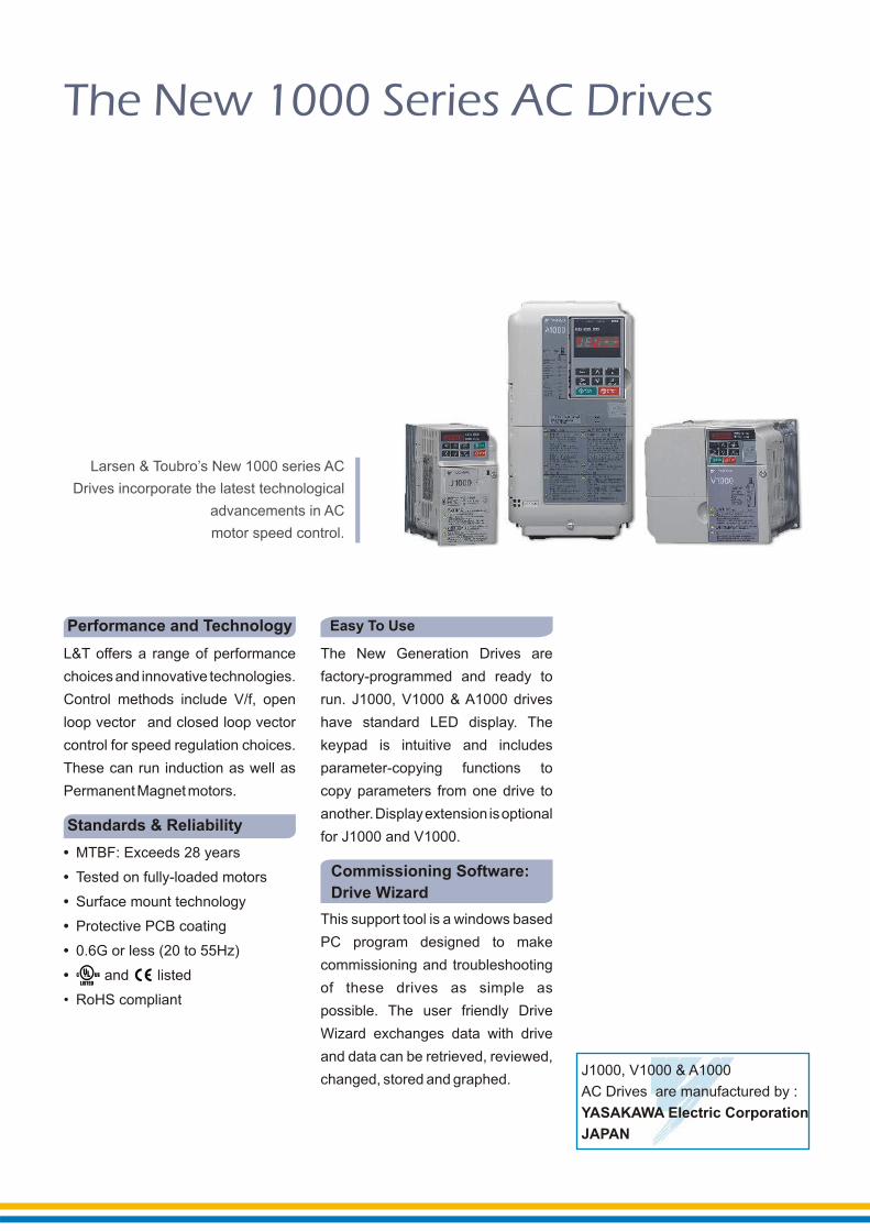
The New 1000 Series AC Drives
J1000, V1000 & A1000
AC Drives are manufactured by :
YASAKAWA Electric Corporation
JAPAN
The New Generation Drives are
factory-programmed and ready to
run. J1000, V1000 & A1000 drives
have standard LED display. The
keypad is intuitive and includes
parameter-copying functions to
copy parameters from one drive to
another.Displayextension isoptional
for J1000 and V1000.
L&T offers a range of performance
choices and innovative technologies.
Control methods include V/f, open
loop vector and closed loop vector
control for speed regulation choices.
These can run induction as well as
PermanentMagnetmotors.
Performance and Technology
Larsen & Toubro’s New 1000 series AC
Drives incorporate the latest technological
advancements in AC
motor speed control.
This support tool is a windows based
PC program designed to make
commissioning and troubleshooting
of these drives as simple as
possible. The user friendly Drive
Wizard exchanges data with drive
and data can be retrieved, reviewed,
changed, stored and graphed.
Commissioning Software:
Drive Wizard
• MTBF: Exceeds 28 years
• Tested on fully-loaded motors
• Surface mount technology
• Protective PCB coating
• 0.6G or less (20 to 55Hz)
• and listed
• RoHS compliant
Standards & Reliability
Torque limit
Heat sink over-heat to give overload protection to inverter
Motor overload protection
Phase-to-phase, ground fault and short circuit protection
Over/under torque protection
Input/output single phasing protection
Optically-isolated controls: to completely isolate control circuit from power circuit
Protection
1
L&T SWITCHGEAR
S A F E & S U R E
Low noise operation
High starting torque
High slip breaking
Volts/Frequency ratio: fullyadjustable
Kinetic energy buffering
Over-voltage suppression
Drive efficiency: 96 to 98%
Output frequency: 1.0 to 400 Hz
Torque boost: full range
Auto carrier reduction
Performance Monitors
Performance Features
Digital keypad operator
Copy keypad function
24 VDC control logic for sourcing sourcing outputs (both PNP or NPN transistors)
RJ-45 style digital operator connector
Multi speed settings plus jog speed
Flash RAM software memory for update
Split front cover for easy wiring
Heat sink fan: Plug-in with on-offcontrol
Functions
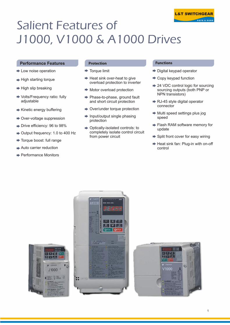
Salient Features ofJ1000, V1000 & A1000 Drives

The J1000 series offers ultimate
ease of use, portability and
opt ions for wide ranging
applications.
With this series, L&T brings
international standard inverter
drive that meet all automation
requirements for compact
applications with variable speed
operation and energy saving
characteristics. A wide range of
useful functions upgrade your
machine and offer greater
potential.
The concept of small size and
easy handling makes the J1000 a
handy alternative in the drive
m a r k e t n o t o n l y f o r i t s
performance but also for
economy of cost.
• Conveyor
• Pump
• Grinder
• Hoist
• Crane
• Screw Feeder
• Escalator
• Fan
• Elevator (door)
Common Applications
V/f Control
Plug’n Play installation function
High flux braking function
Easy parameter programmingand controller functions
Braking Chopper built-in
Heavy duty / normal duty rating
9 step speed
Slip compensation
Speed search
Momentary power log the ride through
Features
2
Micro Size OEM DriveJ1000
L&T SWITCHGEAR
S A F E & S U R E
J10
00
3
Specifications
Co
ntr
olF
un
ctio
ns
Fu
nctio
na
lity
Pro
tection
Functio
ns
Control methods V/f Control
Starting Torque 150%/3Hz
Speed Control Range 1:20~1:40 (V/f control)
Output frequency Range 0.01 Hz to 400 Hz
Frequency Reference Digital set value: ±0.01% (-10..+50°C)Accuracy Analogue set value: ±0.5% (25±10°C)
Resolution of frequency Digital set value: 0.01 Hz (<100Hz), 0.1 Hz (>100 Hz)Analogue set value: 1/1000 of maximum frequency (10 bit)
Resolution of output frequency 0.001 Hz
Heavy duty use: 150% rated output current for one minuteOverload capability Normal duty use: 120% rated output current for one minute
V/f Characteristics Preset V/f patterns and user-set program available
Analogue Inputs 1 analogue input: 0..10 V (20kÙ) at 0/4..20 mA (250kÙ)
Analogue Outputs 1 analogue output: 0..10V
Deceleration/acceleration times 0.01 Sec. to 6000 s
5 digit, 7 Segment LEDDisplay Error and status LED
Motor overload protection Motor overheat protection via output current sensor
Instantaneous overcurrent Drive stops when output exceeds 200% of the rated current (Heavy Duty)
Overload Heavy duty: A stop command will be entered after operative at 150% for 60 secNormal duty: A stop command will be entered after operative at 120% to 60 sec
Overvoltage Motor coasts to a stop if DC Bus voltage exceeds 820V for 400V class (410V for 200V class)
Drive stops when DC Bus voltage falls below following levels:Undervoltage 190V (3-phase 200V), 160V (Single-phase 200V), 380V (3-phase 400V)
Momentary power loss Following items are selectable: not provided (stop if power loss is 15 ms or longer), continuous operation if power returns within set time, Drive will restart if power returns as long as the CPU is working.
Cooling fin overheat Protected by thermistor
Stall prevention level Stall prevention is available during acceleration, deceleration and during run. type of stall prevention determine the current level at which stall prevention is triggered.
Ground fault Protected by electronic circuit (triggered by the same level as momentary current protection)
Degree of Protection IP20, NEMA1 available as an option
Ambient humidity 95% RH or less (without condensation)
Storage temperature -20°C to +60°C (short-term temperature during transportation)
Installation Indoor (no corrosive gas, dust, etc.)
Installation height Max. 1000 m (output derating of 1% per 100 m above 1000 m, max. 3000 m)
Vibration Up to 1G at 10 to 20 Hz, Up to 0.6G at 20 to 55 Hz
Setting
set value
Separate settings for each
Am
bie
ntC
on
ditio
ns
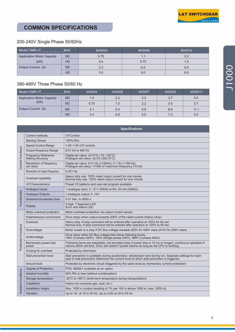
COMMON SPECIFICATIONS
200-240V Single Phase 50/60Hz
Output Current (A)
(kW)
Application Motor Capacity ND
0.75
4.1
3.4
1.5 2.2
1.5
5.4
4.8
HD
HD
ND
380-480V Three Phase 50/60 Hz
4A0004 4A0005
3.0
2.2
6.9
5.5
4A0007
3.7
3.0
8.8
7.2
4A0009
5.5
3.7
11.1
9.2
4A00011Model CIMR-JT_ _ _ _ _ _ _ _ _BAA
Application Motor Capacity
Output Current (A)
HD(kW)
HD
ND
ND 0.75
0.4
3.3
3.0
BA0003
1.1
0.75
6.0
5.0
BA0006
2.2
1.5
9.5
8.0
BA0010Model CIMR-JT_ _ _ _ _ _ _ _ _BAA

The V1000 drive is incredibly
compact, technologically advanced,
env i ronmenta l ly respons ib le
package capable of driving induction
as well as synchronous motor. With
its preset application function and
dual rating it can handle wide variety
of application ranging from Fan,
Pump Compressor, Elevator, Crane
Conveyor and many more. V1000
employs dual CPU concept that is 4
times faster than other drives, which
improves motor control performance
especia l ly in vector contro l
applications. Custom software,
network communications, plugin I/O
cards, packaging options as among
the many choices. V1000 with its
highly advanced features stands out
in its class and a perfect solutions for
most of your applications.
• Pump
• Fan
• HVAC (AHU)
• Conveyor
• Air Compressor
• Crane Hoist
• Crane (Travel)
• Elevator
• Packaging machines
• Extruders
• Centrifuge
Compact Current
Control Vector Drive
Normal & Heavy Duty
V1000
4
Common Applications Features
10 years performance life design
Normal Duty and Heavy Duty selection depending on the application
Single drive for both Induction &permanent magnet motors
Drive customization / PLC functionality
Dual microprocessor for faster control
Rotation & Static Auto-tuning
On-line Auto-tuning
200% starting torque
Allows side by side mounting-reduces panel space
High flux braking for faster stopping without use of braking resistors
Intelligent detachable terminal block
Stores last 10 faults
High speed serial communication at 115kbps
Optional LCD operator

L&T SWITCHGEAR
S A F E & S U R E
*1: Drives with a single-phase power supply input have Three-phase output and cannot be used for single phase motors.
*2: Based on a standard 4-pole motor for max. applicable motor output.
Note: Value inside parenthesis is for a single-phase drive.
200 V Class (Three-phase/Single-phase)
Normal Duty
Heavy Duty
Normal Duty
Heavy Duty
Normal Duty
Heavy Duty
Normal Duty
-
18.5
15.0
85.6
70.8
-
-
26.3
Heavy Duty 22.9
Normal Duty 69.0
Heavy Duty 60.0
Model
0.75
0.4
3.9
2.9
7.3
5.5
1.3
0003
1.1
3.5(3.3)
3.0
0004
1.1
0.75
7.3
5.8
13.8
11.0
2.3
0006
1.9
6.0
5.0
0006
2.2
1.5
10.8
7.5
20.2
14.1
0010
3.7
3.0
9.6
8.0
0010
5.5
3.7
24.0
18.9
-
35.0
0018
7.5
6.7
19.6
17.5
0020
7.5
5.5
34.7
26.0
-
-
-
11.4
9.5
30.0
250
0030
11.0
7.5
50.9
35.4
-
-
-
15.2
12.6
40.0
33.0
0040
15.0
11.0
69.4
51.9
-
-
-
21.3
17.9
56.0
47.0
0056 0069Three-Phase CIMR-VT2A*1
Single-Phase CIMR-VTBA
Max. Applicable Motor*2
Capacity (kW)
Inp
ut
Rated InputCurrent (A)
Rated OutputCapacity (kVA)
Three-Phase
Single-Phase
Ou
tpu
t
Rated Output Current (A)
Overload Tolerance
3.0
2.2
13.9
11.0
24.0
20.6
0012
4.6
4.2
12.0
11.0
0012
2 kHz (user-set, up to 15 kHz possible)
Three-Phase Power Supply: Three-Phase 200 to 240 V (relative to input voltage)
Single-Phase Power Supply: Three-Phase 200 to 240 V (relative to input voltage)
400 Hz
Three-Phase Power Supply: Three-Phase 200 to 240 V 50/60 Hz
Single-Phase Power Supply: Single-Phase 200 to 240 V 50/60 Hz
- 15 to 10%
±5%
Carrier Frequency
Max. Output Voltage
Max. Output Frequency 400 Hz
Po
we
r Rated Voltage/Rated Frequency
Allowable Voltage Fluctuation
Allowable Frequency Fluctuation
Normal Duty Rating: 120% of rated output current for 60 sec
Heavy Duty Rating: 150% of rated output current for 60 sec
400 V Class (Three-phase)
*1: Based on a standard 4-pole motor for max. applicable motor output.
Rated Output Current (A)
Max. Applicable Motor*1
Capacity (kW)
Normal Duty
Heavy Duty
Normal Duty
Heavy Duty
Normal Duty
Heavy Duty
Normal Duty
Heavy Duty
0002
0.75
0.4
2.1
1.8
1.6
1.4
2.1
1.8
0004
1.5
0.75
4.3
3.2
3.1
2.6
4.1
3.4
0005
2.2
1.5
5.9
4.4
4.1
3.7
5.4
4.8
0007
3.0
2.2
8.1
6.0
5.3
4.2
6.9
5.5
0009
3.7
3.0
9.4
8.2
6.7
5.5
8.8
7.2
0011
5.5
3.7
14.0
10.4
8.5
7.0
11.1
9.2
0018
7.5
5.5
20.0
15.0
13.3
11.3
17.5
14.8
0023
11.0
7.5
24.0
20.0
17.5
13.7
23.0
18.0
0031
15.0
11.0
38.0
29.0
23.6
18.3
31.0
24.0
0038
18.5
15.0
44.0
39.0
29.0
23.6
38.0
31.0
Model CIMR-VT4A
Input Rated Input Current (A)
Rated OutputCapacity (kVA)
Outp
ut
Overload Tolerance Normal Duty Rating: 120% of rated output current for 60 sec
Heavy Duty Rating: 150% of rated output current for 60 sec
2 kHz (user-set, up to 15 kHz possible)
Three-Phase 380 to 480 V (relative to input voltage)
400 Hz (user-set)
Three-Phase 380 to 480 V 50/60 Hz
- 15 to 10%
±5%
Carrier Frequency
Max. Output Voltage
Max. Output Frequency
Po
we
r
Rated Voltage/Rated Frequency
Allowable Voltage Fluctuation
Allowable Frequency Fluctuation
V1
00
0
5
STANDARD SPECIFICATIONS

COMMON SPECIFICATION
200%/0.5 Hz
50%/6 Hz
Open Loop Vector Control (Current Vector), V/f Control, PM Open Loop Vector Control (for SPM and IPM motors)
Momentary power loss ride-thru, Speed search, Over torque detection, Torque limit, 17-step speed (max),
Accel/Decel time switch, S-Curve accel/decel, 3-wire sequence, Auto-Tuning (Rotational, Stationary tuning
for resistance between lines), Cooling fan on/off switch, Slip compensation, Torque compensation,
Frequency jump, Upper/Lower limits for frequency reference, DC lnjection braking at start and stop, High slip
braking, PID control (With sleep function), Energy saving Control, Memobus comm. (RS-485/422 max 115.2 kbps),
Fault restart, Application presets, Removable terminal block with parameter backup function
Motor overheat protection based on output current, Momentary over-current protection, Overload p , Over-voltage
protection, Undervoltage protection, Momentary power loss ride-thru, Heatsink oveheat,
Braking resistance overheat protection, Stall prevention, Ground fault protection
rotection
6
L&T SWITCHGEAR
S A F E & S U R E
V1
00
0
7
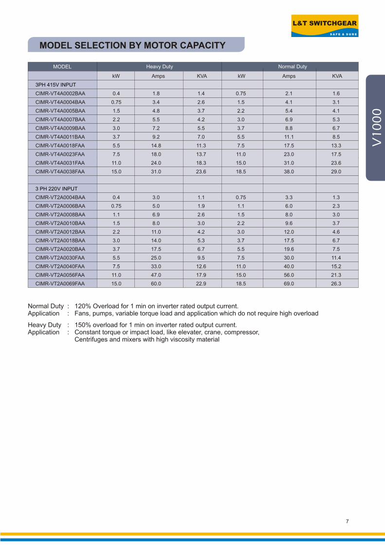
MODEL SELECTION BY MOTOR CAPACITY
Normal Duty : 120% Overload for 1 min on inverter rated output current.Application : Fans, pumps, variable torque load and application which do not require high overload
Heavy Duty : 150% overload for 1 min on inverter rated output current.Application : Constant torque or impact load, like elevater, crane, compressor,
Centrifuges and mixers with high viscosity material
3PH 415V INPUT
3 PH 220V INPUT
CIMR-VT4A0002BAA 0.4 1.8 1.4 0.75 2.1 1.6
CIMR-VT4A0004BAA 0.75 3.4 2.6 1.5 4.1 3.1
CIMR-VT4A0005BAA 1.5 4.8 3.7 2.2 5.4 4.1
CIMR-VT4A0007BAA 2.2 5.5 4.2 3.0 6.9 5.3
CIMR-VT4A0009BAA 3.0 7.2 5.5 3.7 8.8 6.7
CIMR-VT4A0011BAA 3.7 9.2 7.0 5.5 11.1 8.5
CIMR-VT4A0018FAA 5.5 14.8 11.3 7.5 17.5 13.3
CIMR-VT4A0023FAA 7.5 18.0 13.7 11.0 23.0 17.5
CIMR-VT4A0031FAA 11.0 24.0 18.3 15.0 31.0 23.6
CIMR-VT4A0038FAA 15.0 31.0 23.6 18.5 38.0 29.0
CIMR-VT2A0004BAA 0.4 3.0 1.1 0.75 3.3 1.3
CIMR-VT2A0006BAA 0.75 5.0 1.9 1.1 6.0 2.3
CIMR-VT2A0008BAA 1.1 6.9 2.6 1.5 8.0 3.0
CIMR-VT2A0010BAA 1.5 8.0 3.0 2.2 9.6 3.7
CIMR-VT2A0012BAA 2.2 11.0 4.2 3.0 12.0 4.6
CIMR-VT2A0018BAA 3.0 14.0 5.3 3.7 17.5 6.7
CIMR-VT2A0020BAA 3.7 17.5 6.7 5.5 19.6 7.5
CIMR-VT2A0030FAA 5.5 25.0 9.5 7.5 30.0 11.4
CIMR-VT2A0040FAA 7.5 33.0 12.6 11.0 40.0 15.2
CIMR-VT2A0056FAA 11.0 47.0 17.9 15.0 56.0 21.3
CIMR-VT2A0069FAA 15.0 60.0 22.9 18.5 69.0 26.3
MODEL Heavy Duty Normal Duty
kW Amps KVA kW Amps KVA
Common Applications
• Conveyors
• Mixers
• Machine tools
• Cut-to-length
• Centrifugal Pumps
• Centrifuges
• Extruders
• Packaging Machines
• HVAC
• Fan
• Compressor
10 years performance life design
Uses most advanced drive
technology to run induction and
synchronous motors
Positioning accuracy without use
of external sensors
Excellent torque characteristics
Loaded with new auto-tuning
features
Tackles power loss
Easy setup with application
presets
Open to all serial network
protocols
Easy to maintain
10 years performance life design
Environment friendly
Features
8
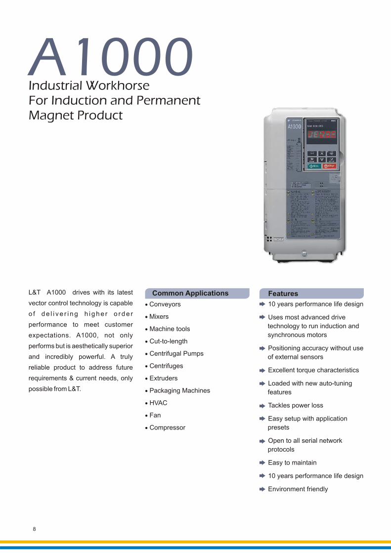
Industrial WorkhorseFor Induction and PermanentMagnet Product
A1000
L&T A1000 drives with its latest
vector control technology is capable
o f d e l i v e r i n g h i g h e r o r d e r
performance to meet customer
expectations. A1000, not only
performs but is aesthetically superior
and incredibly powerful. A truly
reliable product to address future
requirements & current needs, only
possible from L&T.

L&T SWITCHGEAR
S A F E & S U R E
A1
00
0
STANDARD SPECIFICATIONS
9
Optional
Optional

OPTIONS, PERIPHERAL DEVICES
10
Applied to further improve thepower factor of the inverter.
The Varispeed A1000 incorporatesDC Reactor on model of 22kW
or more.
OutputReactor
SemiconductorFuse
Accessories
Type Cat. Nos. Function
Complementry
PG cardPG-B3
Line DriverPG card PG-X3
CommunicationOption Cards
SI-P3
SI-P3/V
SI-N3
SI-N3/V
SI-C3 CC-Link interface card
CAN open interface card
MECHTOLINK-II interface card
Memobus / modbus interface card
Digital LCD operator display
USB Copy unit for copy & verifyfunctions
SI-S3
SI-T3
SI-485/J
JVOP-180
JVOP-181
For speed feedback input by connecting a motor encoder Input: 3 track (can be used with one or two tracks), for HTL encoder connection, 50 kHz max; Output: 3 track, open collector Encoder power supply: 12 V, max current 200 mA
For speed feedback input by connecting a motor encoder Input: 3 track (can be used with one or two tracks), line driver, 300 kHz max; Output: 3 track, line driver Encoder power supply: 5 V or 12 V, max current 200 mA
Profibus-DP interface cards
DeviceNet interface cards
Applicable For
A1000
A1000
A1000
V1000
A1000
V1000
A1000
J1000
V1000 & A1000

L&T SWITCHGEAR
S A F E & S U R E
Dyanamic Braking Unit (DBU) Dynamic Braking Resistance (DBR)Motor(kW)
0.4
0.75
1.5
2.2
3.7
5.5
7.5
11
15
18.5
22
30
37
45
55
75
90
110
132
160
185
220
250
315
355
ND/HD
HD
HD
HD
HD
HD
HD
HD
HD
HD
HD
HD
HD
HD
HD
HD
HD
HD
HD
HD
HD
HD
HD
HD
ND
ND
ND
ND
ND
ND
ND
ND
ND
ND
ND
ND
ND
ND
ND
ND
ND
ND
ND
ND
ND
ND
ND
Drive Model
CIMR-VT4A*******CIMR-AD4A*******
CIMR-JT4A*******CIMR-VT4A*******CIMR-AD4A*******
CIMR-VT4A*******CIMR-AD4A*******
CIMR-AD4A*******
CDBR-4045
Cat. No.
Built In
Built In
Built In
Built In
Built In
Built In
Built In
Built In
Built In
Built In
Built In
Built In
Built In
Built In
Built In
Built In
Built In
Built In
Built In
Built In
Built In
Built In
Built In
Built In
CDBR-4045
CDBR-4045
CDBR-4045
CDBR-4030
CDBR-4030
CDBR-4045
CDBR-4220
CDBR-4220
CDBR-4220
CDBR-4220
CDBR-4220
CDBR-4220
CDBR-4220
CDBR-4220
Quantity
-
-
-
-
-
-
-
-
-
-
-
-
-
-
-
-
-
-
-
-
-
-
-
-
1
1
1
2
2
2
1
1
1
1
1
1
2
2
70
70
260
260
390
520
780
1040
1560
4800
4800
6000
6000
9600
9600
9600
6000
6000
9600
9600
6000
9600
9600
9600
9600
9600
9600
9600
750
750
400
250
150
100
75
50
40
32
27.2
20
20
16
13.6
13.6
20
20
13.6
13.6
20
13.6
13.6
13.6
16
16
13.6
13.6
1
1
1
1
1
1
1
1
1
1
1
1
1
1
1
2
2
2
3
4
4
4
5
5
6
8
DBU & DBR selection Chart for400V J1000 / V1000 / A1000 AC drives
Note:1) Duty factor = 10% ED, for 10 seconds only; This chart is not applicable for Hoist / Elevator motions2) DBU shall be purchased from L&T however DBR of given values must be purchased from local vendors 3) ND = Normal Duty ; HD = Heavy Duty
11
Op
tio
ns
&A
cce
sso
rie
s

12
Guideline For Panel ComponentSelection : A1000/V1000/J1000 Drive
Note:1) For any other make for fuses, kindly insure pre-arc I ^ 2 t value mentioned in the bracket.2) Motor kW refers to a 4-pole motor. Rated output current of drive should be equal to or greater than the motor rated current.3) DN3-630S TM for 185 & 22kW motor is thermal-magnetic realease dsine MCCB.4) Panel Fan EBM make : 115W.5) Either use input AC choke or use DC choke upto CIMR-AD4A0044FMA models, V1000 and J1000 models.
0.4
0.75
1.5
2.2
3.7
5.5
7.5
11
15
18.5
22
30
37
45
55
75
90
110
132
160
185
220
250
315
355
HD
HD
HD
HD
HD
HD
HD
HD
HD
HD
HD
HD
HD
HD
HD
HD
HD
HD
HD
HD
HD
HD
HD
ND
ND
ND
ND
ND
ND
ND
ND
ND
ND
ND
ND
ND
ND
ND
ND
ND
ND
ND
ND
ND
ND
ND
Cat. No.for
kWMotor
A1000 AC Drive / Inverter / VFD / VFSD/
VVVF Drive
DriveRated
Amp @ 50°C
IncomerMCCB
SemiconductorInput Fuse: 3 quantity
Bussmann(Pre-arc I^2t)
DM16/5 Amp
DM166.3 Amp
DM167.5 Amp
DM1610 Amp
DM1616 Amp
DM10025 Amp
Chokes
I/P ACchoke DC choke
O/PChoke
PanelFanQty.
uH/A uH/A uH/A
HD/ND
Type
CIMR-AD4A0002FMA
CIMR-AD4A0002FMA
CIMR-AD4A0004FMA
CIMR-AD4A0004FMA
CIMR-AD4A0005FMA
CIMR-AD4A0005FMA
CIMR-AD4A0007FMA
CIMR-AD4A0007FMA
CIMR-AD4A0011FMA
CIMR-AD4A0011FMA
CIMR-AD4A0018FMA
CIMR-AD4A0018FMA
CIMR-AD4A0023FMA
CIMR-AD4A0023FMA
CIMR-AD4A0031FMA
CIMR-AD4A0031FMA
CIMR-AD4A0038FMA
CIMR-AD4A0038FMA
CIMR-AD4A0044FMA
CIMR-AD4A0044FMA
CIMR-AD4A0058AMA
CIMR-AD4A0058AMA
CIMR-AD4A0072AMA
CIMR-AD4A0072AMA
CIMR-AD4A0088AMA
CIMR-AD4A0088AMA
CIMR-AD4A0103AMA
CIMR-AD4A0103AMA
CIMR-AD4A0139AMA
CIMR-AD4A0139AMA
CIMR-AD4A0165AMA
CIMR-AD4A0165AMA
CIMR-AD4A0208AMA
1.80 FWH-40B (76)
2.10 FWH-40B (76)
3.40 FWH-50B (135)
4.10 FWH-50B (135)
4.80 FWH-70B (210)
5.40 FWH-70B (210)
5.50 FWH-70B (210)
6.90 FWH-70B (210)
9.20 FWH-90B (360)
11.10 FWH-90B (360)
14.80 FWH-80B (305)
17.50 FWH-80B (305)
18.00 FWH-100B (475)
23.00 FWH-100B (475)
24.00 FWH-125B (800)
31.00 FWH-125B (800)
31.00 FWH-200B (1900)
38.00 FWH-200B (1900)
39.00 FWH-250A (6300)
44.00 FWH-250A (6300)
45.00 FWH-250A (6300)
58.00 FWH-250A (6300)
60.00 FWH-250A (6300)
72.00 FWH-250A (6300)
75.00 FWH-250A (6300)
88.00 FWH-250A (6300)
91.00 FWH-250A (6300)
103.00 FWH-250A (6300)
112.00 FWH-350A (14500)
139.00 FWH-350A (14500)
150.00 FWH-400A (19200)
165.00 FWH-400A (19200)
180.00 FWH-500A (29200)
CIMR-AD4A0208AMA 208.00 FWH-500A (29200)
CIMR-AD4A0250AMA 216.00 FWH-600A (41300)
CIMR-AD4A0250AMA 250.00 FWH-600A (41300)
CIMR-AD4A0296AMA 260.00 FWH-700A (55000)
CIMR-AD4A0296AMA 296.00 FWH-700A (55000)
CIMR-AD4A0362AMA 304.00 FWH-800A (76200)
CIMR-AD4A0362AMA 362.00 FWH-800A (76200)
CIMR-AD4A0414AMA 370.00 FWH-800A (76200)
CIMR-AD4A0414AMA 414.00 FWH-800A (76200)
CIMR-AD4A0515AMA 450.00 FWH-1000A (92000)
CIMR-AD4A0515AMA 515.00 FWH-1000A (92000)
CIMR-AD4A0675AMA 605.00 FWH-1200A (122000)
CIMR-AD4A0675AMA 675.00 FWH-1200A (122000) 31/800
18000/2
18000/2
8400/4
8400/4
4200/5.5
4200/5.5
3600/7.5
3600/7.5
2200/10
2200/10
1420/15
1420/15
1060/20
1060/20
700/30
700/30
530/40
530/40
420/50
420/50
360/60
360/60
260/80
260/80
240/90
240/90
180/120
180/120
150/150
150/150
110/200
110/200
90/250
90/250
90/250
90/250
60/330
60/330
60/330
60/330
40/490
40/490
40/490
40/490
30/660
30/660
28000/3.2
28000/3.2
28000/3.2
28000/3.2
11000/5.7
11000/5.7
11000/5.7
11000/5.7
6300/12
6300/12
3600/23
3600/23
3600/23
3600/23
1900/33
1900/33
1900/33
1900/33
1300/47
1300/47
Built In
Built In
Built In
Built In
Built In
Built In
Built In
Built In
Built In
Built In
Built In
Built In
Built In
Built In
Built In
Built In
Built In
Built In
Built In
Built In
Built In
Built In
Built In
Built In
Built In
Built In
1
1
1
1
1
1
1
1
1
1
1
1
1
1
1
1
1
1
1
1
1
1
1
1
1
1
1
1
1
1
1
1
1
1
1
1
2
2
2
2
3
3
3
3
4
4
8072/2
8072/2
6538/4.2
6538/4.2
3710/5.5
3710/5.5
2446/7
2446/7
1899/12
1899/12
1076/18
1076/18
807/25
807/25
538/35
538/35
448/38
448/38
359/45
359/45
294/60
294/60
231/70
231/70
190/85
190/85
161/100
161/100
115/140
115/140
90/180
90/180
77/216
77/216
67/240
67/240
50/320
50/320
45/360
45/360
34/475
34/475
26/630
26/630
31/800
DM10025 Amp
DM10035 Amp
DM10050 Amp
DM10050 Amp
DM10070 Amp
DM10080 Amp
DN2-250M100 Amp
DN2-250M125 Amp
DN2-250M160 Amp
DN2-250M250 Amp
DN2-250M250 Amp
DN3-400M320 Amp
DN3-400M400 Amp
DN3-400M400 Amp
DTH800800 Amp
DN3-630S TM630 Amp
DN3-630S TM630 Amp
DTH800/800A
L&T SWITCHGEAR
S A F E & S U R E
Op
tio
ns
&A
cce
sso
rie
s
13
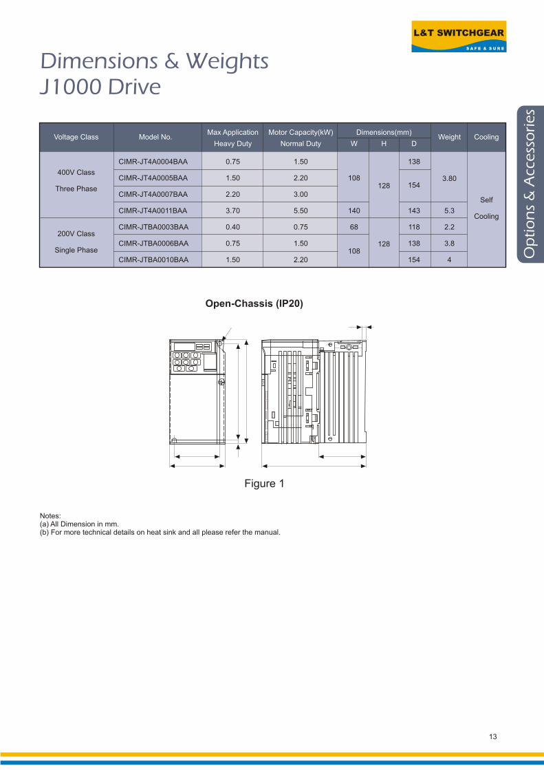
Dimensions & WeightsJ1000 Drive
Max Application Motor Capacity(kW) Dimensions(mm)Voltage Class Model No. Weight Cooling
Heavy Duty Normal Duty W H D
CIMR-JT4A0004BAA 0.75 1.50 138
400V ClassCIMR-JT4A0005BAA 1.50 2.20 108 3.80
154128Three PhaseCIMR-JT4A0007BAA 2.20 3.00
Self
CIMR-JT4A0011BAA 3.70 5.50 140 143 5.3Cooling
CIMR-JTBA0003BAA 0.40 0.75 68 118 2.2200V Class
CIMR-JTBA0006BAA 0.75 1.50 138 3.8128Single Phase 108
CIMR-JTBA0010BAA 1.50 2.20 154 4
Figure 1
Open-Chassis (IP20)
Notes:(a) All Dimension in mm.(b) For more technical details on heat sink and all please refer the manual.
14
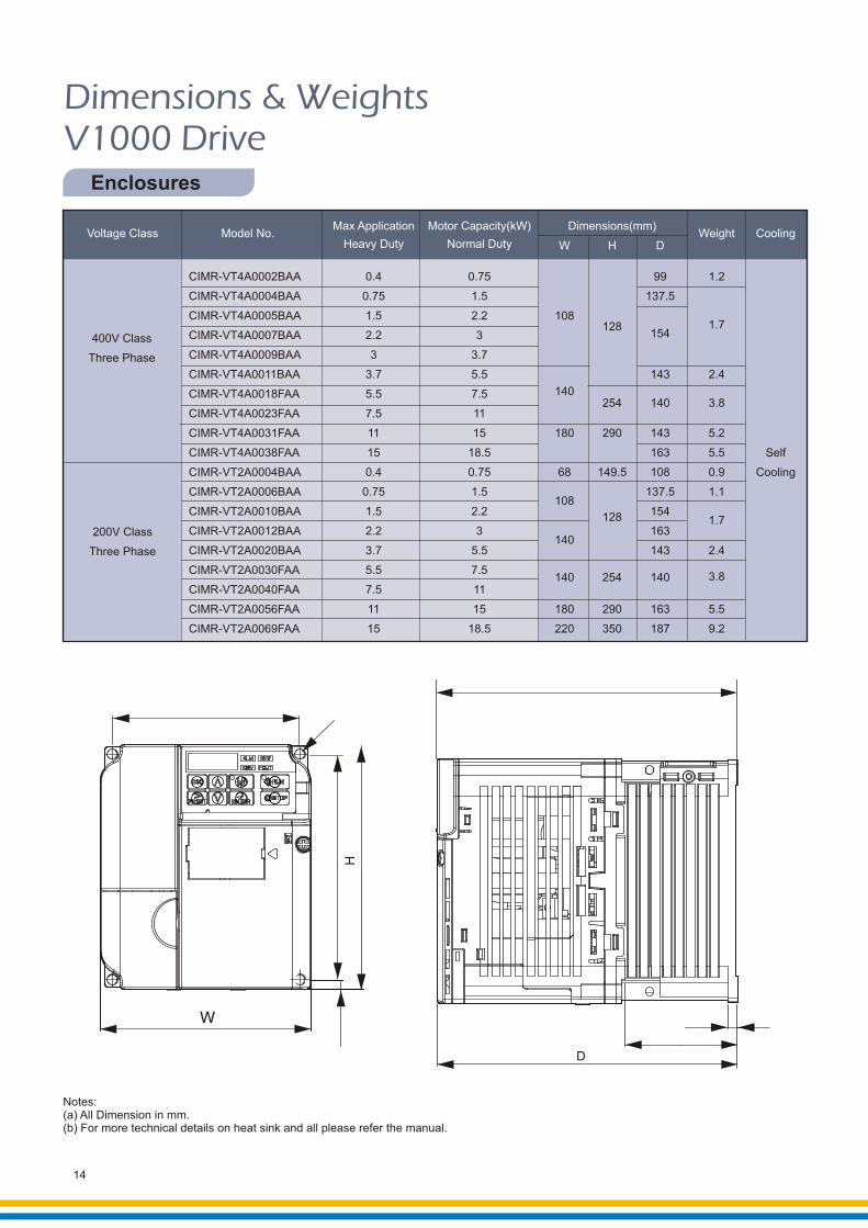
DimensionsV1000 Drive
& Weights
Enclosures
Notes:(a) All Dimension in mm.(b) For more technical details on heat sink and all please refer the manual.
Max Application Motor Capacity(kW) Dimensions(mm)Voltage Class Model No. Weight Cooling
Heavy Duty Normal Duty W H D
CIMR-VT4A0002BAA 0.4 0.75 99 1.2
CIMR-VT4A0004BAA 0.75 1.5 137.5
CIMR-VT4A0005BAA 1.5 2.2 1081.7128
154CIMR-VT4A0007BAA 2.2 3400V Class
CIMR-VT4A0009BAA 3 3.7Three Phase
CIMR-VT4A0011BAA 3.7 5.5 143 2.4
140CIMR-VT4A0018FAA 5.5 7.5254 140 3.8
CIMR-VT4A0023FAA 7.5 11
CIMR-VT4A0031FAA 11 15 180 290 143 5.2
CIMR-VT4A0038FAA 15 18.5 163 5.5 Self
CIMR-VT2A0004BAA 0.4 0.75 68 149.5 108 0.9 Cooling
CIMR-VT2A0006BAA 0.75 1.5 137.5 1.1108
CIMR-VT2A0010BAA 1.5 2.2 154128 1.7
CIMR-VT2A0012BAA 2.2 3 163200V Class140
CIMR-VT2A0020BAA 3.7 5.5 143 2.4Three Phase
CIMR-VT2A0030FAA 5.5 7.53.8140 254 140
CIMR-VT2A0040FAA 7.5 11
CIMR-VT2A0056FAA 11 15 180 290 163 5.5
CIMR-VT2A0069FAA 15 18.5 220 350 187 9.2

L&T SWITCHGEAR
S A F E & S U R E
Dim
en
sio
ns
&W
eig
hts
15
CIMR-AD4A0002FMA
CIMR-AD4A0004FMA
CIMR-AD4A0005FMA
CIMR-AD4A0007FMA
CIMR-AD4A0011FMA
CIMR-AD4A0018FMA
CIMR-AD4A0023FMA
CIMR-AD4A0031FMA
CIMR-AD4A0038FMA
CIMR-AD4A0044FMA
CIMR-AD4A0058AMA
CIMR-AD4A0072AMA
CIMR-AD4A0088AMA
CIMR-AD4A0103AMA
CIMR-AD4A0139AMA
CIMR-AD4A0165AMA
CIMR-AD4A0208AMA
CIMR-AD4A0250AMA
CIMR-AD4A0296AMA
CIMR-AD4A0362AMA
CIMR-AD4A0414AMA
CIMR-AD4A0515AMA
CIMR-AD4A0675AMA
0.75
1.5
2.2
3.0
5.5
7.5
11
15
18.5
22
30
37
45
55
75
90
110
132
160
185
220
250
355
0.4
0.75
1.5
2.2
3.7
5.5
7.5
11
15
18.5
22
30
37
45
55
75
90
110
132
160
185
220
315
140
140
180
220
250
275
325
325
450
500
500
670
260
260
300
350
400
450
510
550
705
800
950
1140
147
164
167
187
197
258
258
283
330
350
370
3.2
3.4
3.5
3.9
5.4
5.7
8.3
21
25
36
41
42
79
96
102
107
125
221
Self
cooling
Fan
cooling
Max. Application Motor Capacity (kw)
Normal Duty Heavy Duty
ModelCIMR-AD4A
Dimensions (mm)
W H D
Weight(kg) Cooling
400 V Class
DimensionsA1000 Drive
& Weights
Notes:(a) All Dimension in mm.(b) For more technical details on heat sink and all please refer the manual.

General Information
An AC or DC reactor should be installed in the following conditions:
• to suppress harmonic currents.
• to suppress peak currents when power factor correction capacitors in the power supply network are
switched.
• when the drive is connected to the same power supply system with thyristor converters like DC
drives.
When running a specialized motor or more than one motor in parallel from a single drive, the capacity
of the drive should be larger than 1.1 times of the total motor rated current.
Terminals B1, B2, F, +1, +2, - are provided for connecting optional features for the drive. Do not
connect other equipment designed by other manufacturers.
Acceleration / deceleration times are affected by how much torque the motor generates the load
torque.
Never connect the power supply lines to output terminals U/T1, V/T2 or W/T3. Doing so will destroy
the drive. Be sure to perform a final check of all sequence wiring and other connections before turning
the power on. Make sure there are no short circuits on the control terminals (+V, AC, etc.), as this
could damage the drive.
As a general principle, the user should avoid opening and closing the magnetic contactor between
the motor and the drive during run. Doing so can cause high peak currents and over current faults. If
magnetic contactors are used to bypass the drive by connecting the motor to the power supply
directly, make sure to close the bypass not before the drive is stopped and fully disconnected from the
motor. If the motor start running even while coasting, select the speed search functions. Set up
delayed release when using a magnetic contactor to handle momentary power loss.
In case of submersible motor, since rated current is greater than a standard motor, select the drive
capacity accordingly. Be sure to use a large enough motor cable to avoid decreasing the maximum
torque level on account of voltage drop caused by a long motor cable.
Variable speed drives are not designed for operating single phase motor. Using a capacitor to start
the motor causes excessive current to flow into the capacitor, potentially causing damage. A slit-
phase start or a repulsion start can end up burning out the starting coils because the internal
centrifugal switch is not activated. The drive can only be used with three phase motors.
16
L&T SWITCHGEAR
S A F E & S U R E
Pro
du
ct
Ra
ng
e
17
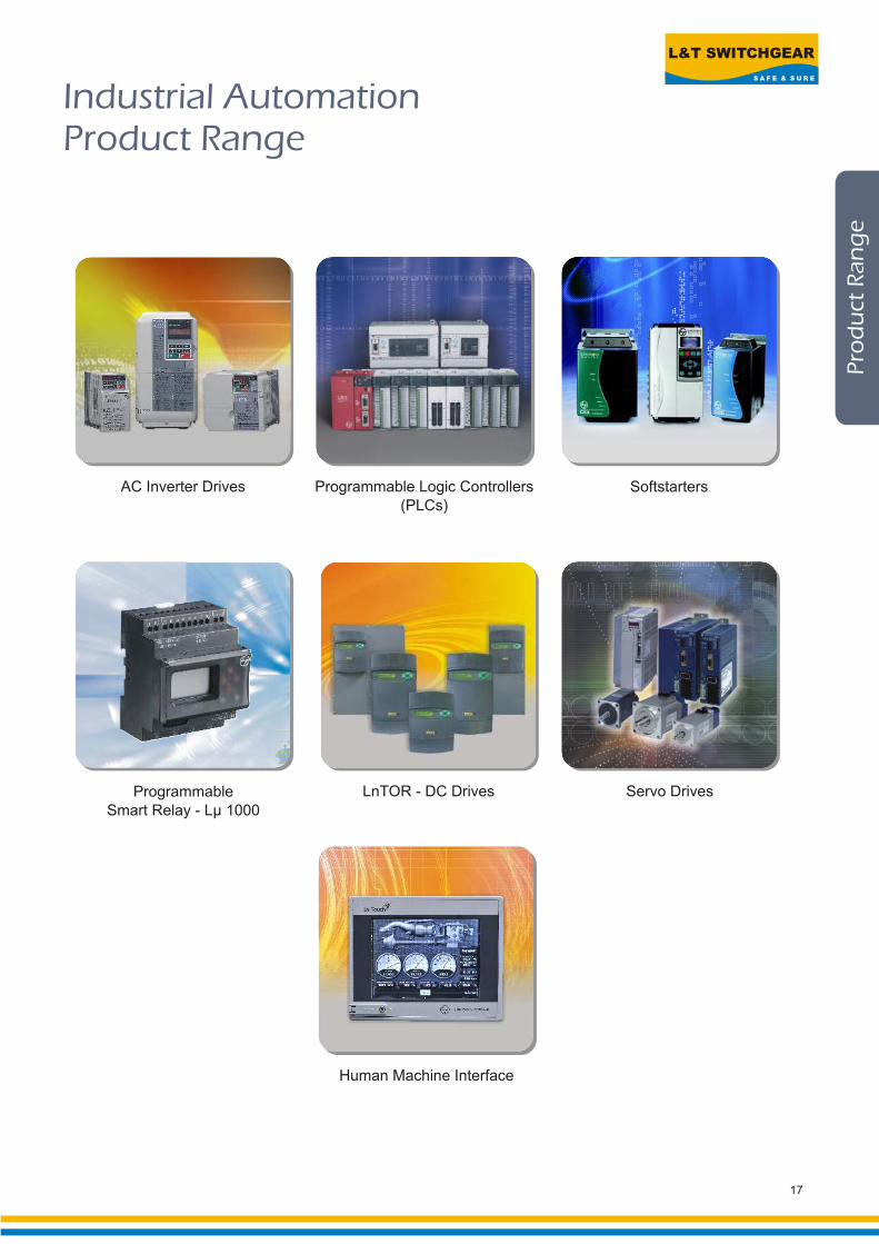
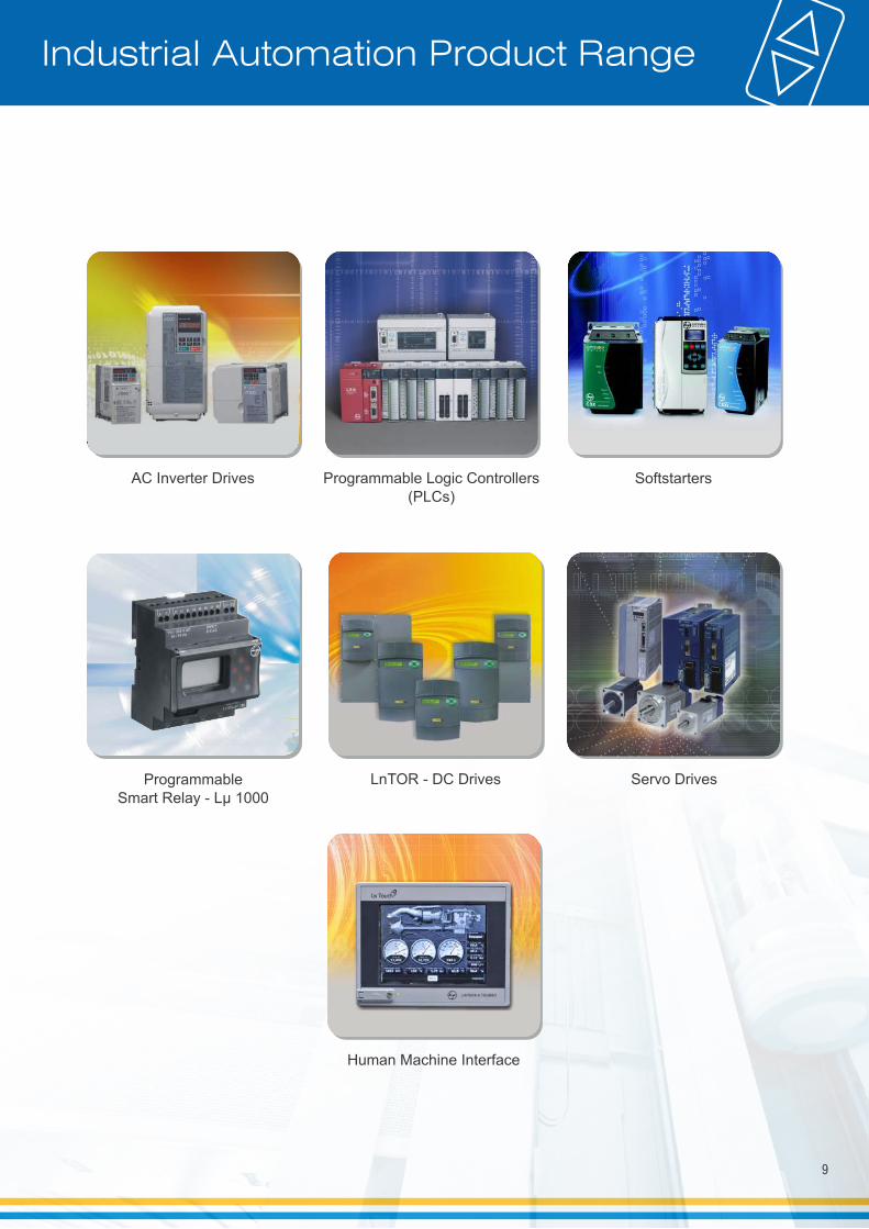
Industrial AutomationProduct Range
Programmable Logic Controllers
(PLCs)
AC Inverter Drives Softstarters
Servo Drives
Human Machine Interface
LnTOR - DC DrivesProgrammable
Smart Relay - Lµ 1000

REGISTERED OFFICE ANDHEAD OFFICEL&T House, Ballard EstateP. O. Box 278Mumbai 400 001Tel: 022-67525656Fax: 022-67525858Website: www.Larsentoubro.com
ELECTRICAL STANDARD PRODUCTS (ESP)501, Sakar Complex IOpp. Gandhigram Rly. Station Ashram RoadAhmedabad 380 009Tel: 079-66304007-11Fax: 079-26580491 / 66304025e-mail: [email protected]
38, Cubbon Road, P. O. Box 5098Bangalore 560 001Tel: 080-25020100Fax: 080-25580525e-mail: [email protected]
131/1, Zone IIMaharana Pratap NagarBhopal 462 011Tel: 0755-4098721 / 7 / 8 / 9Fax: 0755-2769264e-mail: [email protected]
Plot No. 559, Annapurna ComplexLewis RoadBhubaneswar 751 014Tel: 0674-6451342, 2436696Fax: 0674-2537309e-mail: [email protected]
SCO 32, Sector 26-D Madhya Marg, P. O. Box 14Chandigarh 160 026Tel: 0172-4646840, 4646853Fax: 0172-4646802e-mail: [email protected]
10, Club House RoadChennai 600 002Tel: 044-28462072 / 4 / 5 / 2109Fax: 044-28462102 / 3 e-mail: [email protected]
67, Appuswamy RoadPost Bag 7156 Opp. Nirmala CollegeCoimbatore 641 045Tel: 0422-2588120 / 1 / 5Fax: 0422-2588148e-mail: [email protected]
Product improvement is a continuous process. For the latest information and special applications, please contact any of our offices listed here.
Electrical Standard Products (ESP) Branch Offices:
L&T House, Group MIG-5 PadmanabhpurDurg 491 001Tel: 0788-2213833 / 14 / 21 / 29Fax: 0788-2213820
Khairasol, Degaul AvenueDurgapur 713 212Tel: 0343-2559848 / 2559849 / 2559844Fax: 0343-2553614e-mail: [email protected]
Milanpur Road, Bamuni MaidanGuwahati 781 021Tel: 0361-2550568Fax: 0361-2551308e-mail: [email protected]
II Floor, Vasantha Chambers5-10-173, Fateh Maidan RoadHyderabad 500004Tel: 040-66720250Fax: 040-23296468e-mail: [email protected]
D-24, Prithvi Raj Road, C-SchemeJaipur 302 001Tel: 0141-2385915 / 16 / 17 / 18Fax: 0141-2373280e-mail: [email protected]
Akashdeep Plaza, 2nd Floor P. O. GolmuriJamshedpur 831 003JharkhandTel: 0657-2340864 / 387Fax: 0657-2341250e-mail: [email protected]
Skybright Bldg; M. G. RoadRavipuram Junction, ErnakulamKochi 682 016Tel: 0484-4409420 / 4 / 5 / 7Fax: 0484-4409426e-mail: [email protected]
3-B, Shakespeare SaraniKolkata 700 071Tel: 033-44002572 / 3 / 4Fax: 033-22822589e-mail: [email protected]
A28, Indira Nagar, Faizabad Road Lucknow 226 016Tel: 0522-2312904 / 5 / 6Fax: 0522-2311671e-mail: [email protected]
No: 73, Karpaga Nagar,8th StreetK. PudurMadurai 625007Tel: 0452-2537404, 2521068Fax: 0452-2537552e-mail: [email protected]
EBG North Wing Office-Level 2 Gate 7, Powai CampusMumbai 400 072Tel: 022-67052874 / 2737 / 1156Fax: 022-67051112e-mail: [email protected]
#12, Shivaji NagarNorth Ambazari RoadNagpur 440 010Tel: 0712-2260012 / 3Fax: 0712-2260020 / 30e-mail: [email protected]
32, Shivaji Marg P. O. Box 6223New Delhi 110 015Tel: 011-41419514 / 5 / 6Fax: 011-41419600e-mail: [email protected]
L&T House P. O. Box 119191/1, Dhole Patil RoadPune 411 001Tel: 020-26135048Fax: 020-26124910, 26135048e-mail: [email protected]
3rd Floor Vishwakarma ChambersMajura Gate, Ring RoadSurat 395 002Tel: 0261-2473726Fax: 0261-2477078e-mail: [email protected]
Radhadaya ComplexOld Padra RoadNear Charotar SocietyVadodara 390 015Tel: 0265-6613610 / 1 / 2Fax: 0265-2336184e-mail: [email protected]
48-8-16, DwarakanagarVisakhapatnam 530 016Tel: 0891-6620411-2 / 3Fax: 0891-6620416e-mail: [email protected]
SP 50426 R3
Electrical Standard Products
Larsen & Toubro Limited
Powai Campus, Mumbai 400 072
Customer Interaction Center (CIC)
BSNL / MTNL (toll free) : 1800 233 5858
Reliance (toll free) : 1800 200 5858
Tel : 022 6774 5858
Fax : 022 6774 5859
E-mail : [email protected]
Website : www.LNTEBG.com
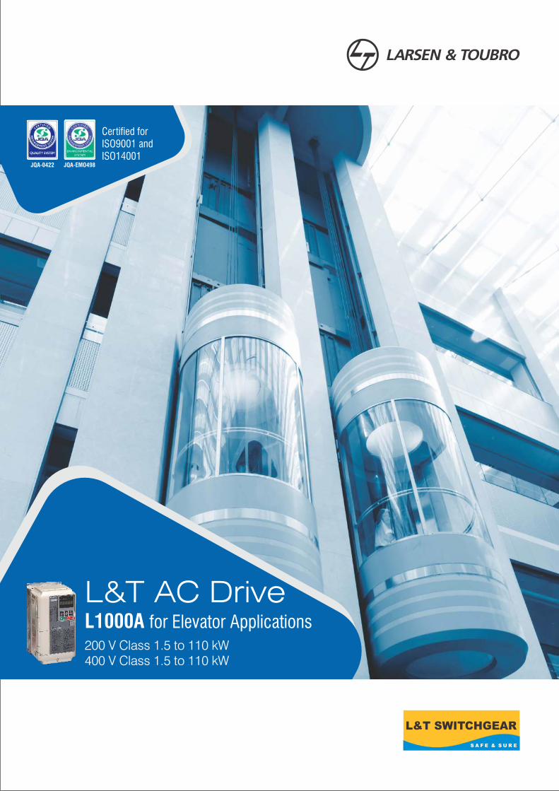
L&T AC DriveL1000A for Elevator Applications200 V Class 1.5 to 110 kW400 V Class 1.5 to 110 kW
Certified forISO9001 andISO14001
JQA-0422 JQA-EMO498

Larsen & Toubro infuses engineering with imagination. The Company offers a wide range of advanced solutions in the
field of Engineering, Construction, Electrical & Automation, Machinery and Information Technology.
L&T Switchgear, a part of the Electrical & Automation business, is India's largest manufacturer of low voltage
switchgear, with the scale, sophistication and range to meet global benchmarks. With over five decades of experience
in this field, the Company today enjoys a leadership position in the Indian market with a growing international
presence.
It offers a complete range of products including powergear, controlgear, industrial automation, building electricals &
automation, reactive power management, energy meters, and protective relays. These products conform to Indian
and International Standards.
L&T introduces L1000A drive designed specifically for the elevator industry.
About us
Powai Switchgear Factory, Mumbai

L1000A drive
L&T L1000A drive is a reliable product with superior aesthetics, power & high performance vector control technology
that meets the current needs & future requirements.
•Easy setup and maintenance
– Terminal block with parameter backup
– DriveWizard Plus
•Safety
– Rescue operation
– Safe disable function
– Fault detection during run
– Preventive warnings
– High performance with low harmonic
distortion
•Setting the trend
– Runs induction and synchronous motors
– Compatible with a wide range of encoders
– Reduced operation time and more powerfulbraking
– Direct-to-floor
– Short floor
• Smooth, comfortable ride
– Smooth operation
– High starting torque without sensors
– Overshoot and anti-vibration control
– Variety of braking functions
– Anti-rollback
Features
1

Setting the Trend
u Cutting-edge drive technology to run a newly installed gearless synchronous motor, or a refurbished geared induction motor.
Minimizes equipment required for your application.
Capacity Range
200 V Class 1.5 to 110kW400 V Class 1.5 to 110kW
Control Mode
PM motors ・Closed Loop Vector Control for PM motors (SPM/IPM drive)
Induction motors ・V/f ControlOpen Loop Vector ControlClosed Loop Vector Control
・・
Runs Induction and Synchronous Motors
L1000A
Induction motorSynchronous SPM motor(base-mount)
Synchronous IPM motor(ultra-thin)
Use parameters to switch between motor types
Control Mode Starting TorqueSpeedRange
Motor Encoders and Option Cards
V/f Control 500% at 3Hz* N/A
Open Loop Vector Control
200% at 0.3 Hz* N/A
Closed Loop Vector Control
200% at0 r/min*1
1:40
1:200
1:1500Incremental Encoders:·PG-X3 (Line Driver)·PG-B3 (Complementary)
Closed Loop Vector Control for PM
200% at0 r/min*
1:1500
Incremental Encoders:·PG-X3 (Line Driver) ·PG-B3 (Complementary) Absolute Encoders: ·PG-F3(EnDat) ·PG-E3(ERN1387)
Loaded with Auto - Tuning Features
u
u
“Direct-to-Floor” functionImproves operational efficiency as well as ensures superior stopping precision.
Short Floor minimizes the creep speed time
Improved operation efficiency
to minimize operation time.
Reduced Operation Time and More Powerful Braking
u Faster Operation Time u Short Flooru Direct-to-Floor
Floor Contact (if avaiable)
Stop
Stopping distance correction at stop
contact (if available)
Stopping distance set in the drive
Stopping distanceset in the drive
Speedreference Stopping
distance
LevelingStopFloor
Contact(if available)
Stop
Stop
Actualstoppingdistance setin the drive
Stoppingdistancecalculated inthe drive fromride profilesettings
Stoppingdistance correction at stop contract(if available)
Leveling
* Drive and motor must be matched appropriately.
High-performance current vector control generates torque and precision control at low speeds.
powerful starting
Interface to match gear-less, SPM synchronous motors and every type of absolute encoder. High resolution and pole position detection for a smooth and safe ride.
u
u
Compatible with a Wide Range of Encoders
2
Applications requiring high starting torque, high speed, and high accuracy. Tuning is performed on the motor alone, decoupled from the load.
Applications where the motor must remain connected to the load during the auto-tuning process.
For re-tuning when the cable length between the motor/drive has changed or when motor/drive capacities are different.
Fine tunes the home pulse position when using an encoder with a synchronous motor. Possible with both Rotational andStationary Auto-Tuning.
RotationalAuto-Tuning
StationaryAuto-Tuning
Motor ResistanceAuto-Tuning
Encoder OffsetAuto-Tuning
Motor Tuning
u
Loaded with a variety of Auto-Tuning methods to ensure top performance.
Motor tuning features optimize drive settings disconnect the rope or car.
Tuning features for connected machinery.
without needing to
u
u
u
u

Smooth, Comfortable Ride
u
High Performance Starting Torque without Sensors
• Advanced Anti-Rollback
Kv (C5 parameter)
Torque reference
Processing
+
+
“Position hold”command input
NEW
Kp(S3-01)
Positioning Speed regulator
+
-
+
-
Speed feedbackS3-02
Position feedback
*Advanced Anti-Rollback: Torque compensation function that eliminates shock at start up by
preventing the car from moving when the brake is released.
u
Zero servo gain 2 (S3-02)(Before adjustment)
Torquereference
MotorspeedRollback
Torq
ue
7.5 8 8.5 9 9.5 10 10.5 11 11.5 12
Previous ModelL1000A
Zero servo gain 2 (S3-02)(After adjustment)
Torquereference
Motorspeed
Torq
ue
7.5 8 8.5 9 9.5 10 10.5 11 11.5
RollbackSuppressed
Previous ModelL1000A
3
Ensures smooth ride even without a load sensor, by providing high-performance torque compensation (Advanced Anti-Rollback*) and high resolution absolute encoder
Easy to adjust Anti-Rollback with sensors, preventing shock start and stop
Smooth Operation
Feed Forward achieves ideal speed response, eliminating vibration &
making it easy to tweak the speed control loop (ASR). (available soon)
Adjust jerk settings at the start and end of acceleration and deceleration to
create a perfectly smooth ride.
u
u
Built-in braking transistor up to 18.5 kW
0.4 18.5
Built-in braking transistor up to 30 kW
Previous Models
L1000A
Variety of Braking Functions
Overshoot and Anti - Vibration Control
Secondary current (torque) control
+++
-
Speed reference
Speed detection
• Feed Forward
FeedForwardControl Speed control
u All models up to 30 kW are equipped with a braking transistor for even more powerful braking options by just adding a braking resistor.
• Overshoot Compensation
1050
900
750
00 0.5 1
Previous Speed Control
Time (s)
w/Feed Forward Control
Spe
ed (
r/m
in)
Time (s)
Suppresses overshoot at the end of acceleration
050
900
750
00 0.5 1
30 kW
• Torque Ripple Comparison (Closed Loop Vector at zero speed)
Time (0.2 s/div)
【Previous model】
【L1000】
(%)
(2%/div)
Torq
ue
u
u
Has half the torque ripple compared to earlier models for an even
smoother ride
Provides precise motor torque performance capability for smoother
acceleration and deceleration

Safety, Easy Setup and Maintenance
Rescue Operation switches to backup battery or UPS in case of a power outage
• UPS Wiring and Operation • Backup Battery Wiring and Operation
*The illustrations above have been simplified, omitting switches and control signals that are otherwise required. Refer to the wiring diagrams included with the components in question.
UPS220 V, single phase
L1000A
24VDC
48-96VDC
24 V power supply unit
L1000A
Protects the elevator application with immediate fault detection.
u
u
Protection over - acceleration, speed reversal, wiring errors, and improper parameter settings.
Immediate response of hardware sensors if the motor encoder signal is lost, ensuring an even higher level of safety.
by detection of
Performance Life Monitors
u L1000A is equipped with performance life monitors that notify the user of part wear and maintenance periods to prevent problems before they occur.
Safe Disable Function
Preventive Warnings
Rescue Operation
Fault Detection During Run
• OveraccelerationFault Detection
*Actual operation varies by the control mode and motor encoder.
L4-13
Accel during normal operation
SpeedMotor speed during fault
Time
Speed
Time
SignalOveraccel
(fault signal)
Closed Open
Motor speed during normal operation
Fault acceleration detection level
Accel during faultAccel
Safety regulations
u Fully compliant with EN954-1 Cat. 3, ISO13849-1 (Cat. 3, PLd), and IEC/EN61058 SIL2, while eliminating the need for extra peripherals. Helps to easily satisfy EU standard for elevators EN81-1.
Operator Display Corresponding Component
LT-1 Cooling fan
LT-2 Capacitor
LT-3 Inrush prevention relay
LT-4 IGBTs
• Alarm Signals Output PLC or Control Device
Monitor status of input power supply
u Customized hardware immediately detects phase loss from the input power supply.
Detection remains active regardless of whether the drive is running or stopped.
An output signal can also be setup if a phase loss occurs.
u Both single-phase and 3-phase 220 V UPS and 48 -96 Vdc(400 V class) battery (24 V control power supply) can keep the elevator running in case of an emergency. Possible with all 200 V and 400 V class models
Automatically speed adjustment during voltage drop to prevent loss in motor speed.
Light Load Direction Search function triggered by UPS and battery voltage
Vdc(200 V class)
u
u
4
No longer needed!
・Space-saving・Highly reliable・Cost-efficient
Emergency stop
Power supply
Motor
Safe Disable wiring example (source mode)
Switch
AC drive
H2
H1
HC24 V
Main power
Power moduleN P
Control circuit
Gate block
Gate block
Jumper S3(set to SOURCE)

Standard Specifications
5
Model CIMR-LT2A 0018 0025 0033 0047 0060 0075 0085 0115 0145 0180 0215 0283 0346 0415
Max. Applicable Motor Capacity kW 3.7 5.5 7.5 11 15 18.5 22 30 37 45 55 75 90 110
Rated Input Current A 18.9 28 37 52 68 80 82 111 136 164 200 271 324 394
Input Power kVA 9.5 14 18 27 36 44 37 51 62 75 91 124 148 180
Rated Output Current A 17.5 25 33 47 60 75 85 115 145 180 215 283 346 415
Rated Output Capacity kVA 6.7 9.5 12.6 17.9 23 29 32 44 55 69 82 108 132 158
Maximum Output Voltage Three-phase 200 to 240 Vac (proportional to input voltage)
Maximum Output Frequency 120 Hz (user adjustable)
Rated Voltage/ Rated Frequency Three-phase 200 to 240 Vac 50/60 Hz 270 to 340 Vdc
Carrier Frequency User adjustable between 2 and 15 kHz User adjustable between 2 and 10 kHz
Item Specifications
200
V Cl
ass
Model CIMR-LT4A 0009 0015 0018 0024 0031 0039 0045 0060 0075 0091 0112 0150 0180 0216Max. Applicable Motor CapacitykW 3.7 5.5 7.5 11 15 18.5 22 30 37 45 55 75 90 110
Rated Input Current A 10.4 15 20 29 39 44 43 58 71 86 105 142 170 207
Input Power kVA 10.0 14.6 19.2 28.4 37.5 46.6 39.3 53.0 64.9 78.6 96.0 129.9 155 189
Rated Output Current A 9.2 14.8 18 24 31 39 45 60 75 91 112 150 180 216Rated Output Capacity kVA 7 11.3 13.7 18.3 24 30 34 48 57 69 85 114 137 165Carrier Frequency User adjustable from 2 to 15 kHz User adjustable from 2 to 10 kHz
Max. Output Voltage Three-phase 380 to 480 V (proportional to input voltage)
Max. Output Frequency 120 Hz (user adjustable)
Rated Voltage/Rated Frequency Three-phase 380 to 480 Vac 50/60 Hz 510 to 680 Vdc
Common Specifications
Allowable Voltage Fluctuation -15 to 10%
Allowable Frequency Fluctuation ±5%
Overload Tolerance 150% of rated output current for 60 s
+
400
V Cl
ass
Harmonics Suppression
Braking Function Braking Transistor Built-in Option Use drive parameters to select from the following control modes:
V/f Control, Open Loop Vector Control, Closed Loop Vector Control, Closed Loop Vector Control for PM
Frequency Control Range 0.01 to 120 HzFrequency Accuracy Digital reference: within ± 0.01% of the max. output frequency (-10 to +40˚C)(Temperature Fluctuation) Analog reference: within ± 0.1% of the max. output frequency (25˚C ± 10˚C)
Digital reference: 0.01 Hz, Analog reference: 0.03 Hz / 60 Hz (11 bit)Output Frequency Resolution 0.001 HzFrequency Setting Resolution -10 to 10 V, 0 to 10 V
150% / 3 Hz (V/f Control) 200%/ 0 r/min (Closed Loop Vector Control)
200% / 0.3 Hz (Open Loop Vector Control) 200% / 0 r/min (Closed Loop Vector Control for PM) 1:40 (V/f Control) 1:1500 (Closed Loop Vector Control)
1:200 (Open Loop Vector Control) 1:1500 (Closed Loop Vector Control for PM)Speed Control Accuracy ± 0.2% in Open Loop Vector Control (25˚C ± 10˚C), ± 0.02% in Closed Loop Vector Control (25˚C ± 10˚C)
10 Hz in Open Loop Vector Control (25˚C ± 10˚C), 50 Hz in Closed Loop Vector +Control (25˚C ± 10˚C)(excludes temperature fluctuation when performing Rotational Auto-Tuning)
Torque Limit All vector control modes allow separate settings in four quadrants with accuracy ± 5%Accel/Decel Time 0.00 to 6000.0 s (4 selectable combinations of independent acceleration and deceleration settings)Braking Torque Approximately 125% when using a braking resistor optionV/f Characteristics User-selected programs and V/f preset patterns possible
Torque compensation at start, Auto-Tuning (for motor and encoder offset), braking sequence, Feed Forward,
Short Floor, Rescue Operation using back-up power supply, Light Load Direction Search,
Removable Terminal Block with Parameter BackupMotor Protection, Momentary Over current Protection, Overload Protection, Overvoltage Protection, Undervoltage
Protection, Heatsink Overheat Protection, Stall Prevention, Ground Fault Protection, Charge LEDArea of Use IndoorsAmbient Temperature - 10 to +50˚CHumidity 95% RH or less (no condensation)Storage Temperature -20 to +60˚C (short-term temperature during transportation)Altitude Up to 1000 meters
2 2Shock 10 Hz to 20 Hz, 9.8 m/s max. 20 Hz to 55 Hz, 5.9 m/s max. UL508C, EN61800-3, EN61800-5-1,EN954-1 Cat. 3, ISO13849-1 (Cat.3, PLd), IEC/EN61508 SIL2
Protective Design
Speed Response
IP20/NEMA Type 1 (CIMR-LT2A0018 to 2A0075 and 4A0009 to 4A0039), IP00 for further models
Direct-to-Floor,
Option Built-inDC Reactor
Control Method
Frequency Setting Resolution
Cont
rol C
hara
cter
istic
s
Starting Torque
Speed Control Range
Main Control Functions
Prot
ectio
n
Main Protection functions
Envi
ronm
ent
Standards Compliant

Peripherals Devices and Options
ERN1387:
Maximum input frequency: 20 kHz
Pulse monitor: Matches RS-422
Voltage output for encoder: 5 V, 200 mA max.
*Encoder cable: 10 m max.
Pulse monitor cable: 30 m max.
*Use a 17-pin encoder cable
For line drivers:
3 track (A, B, Z pulse)
Single track compatible (A pulse)
Maximum input frequency: 300 kHz
Pulse monitor: Matches RS-422
Voltage output for PG: 5 or 12V, max. 200mA
For complimentary and open collector types:
3 track (A, B, Z pulse)
Single track compatible (A pulse)
Maximum input frequency: 50 kHz
Pulse monitor output: Open collector
Voltage output for PG: 12V, max. 200mA
PG-E3Encoder Type (ERN1387)
EnDat2.1/01, EnDat2.2/01:
Maximum input frequency: 20 kHz
Pulse monitor: Matches RS-422
Voltage output for encoder: 5 V, 330 mA max or
8 V, 150 mA max.
Encoder cable: 20 m max.*
Pulse monitor cable: 30 m max.
*Use a 17-pin encoder cable
PG-F3Encoder Type (EnDat)
PG-X3Line Driver PG
PG-B3Complimentary Type PG
Connects the drive to a CANopen network.SI-S3CANopen
Device
PG
Spe
ed C
ontr
olle
r C
ard
Com
mun
icat
ions
Pulse generators
and encoders are
combined with a
feedback signal to
detect motor speed.
Allows the drive to
control the output
frequency to keep
motor speed constant.
PurposeModel
Back power supply for the control circuit and option boards for when the main
circuit loses power. Allows the user to refer to parameter settings and view drive
monitors during a power loss.
PS-A10LPS-A10H
24V Power Supply
Copy parameter settings in a single step, then transfer those settings to another drive.JVOP-181USB Copy Unit
Oth
er O
ptio
nsB
raki
ng
Braking Unit CDBR-4045CDBR-4030
CDBR-4220
Consume regenerative energy from motor in the braking resistor unit at deceleration and improve drive braking ability. *Note: Braking transistor is built-in upto 30 kW.
6
Simplify interfacing with the drive to perform tasks like- Read or modify, copy drive
parameters to another drive, operate the drive and monitor drive status.JVOP-180LCD Display

Braking Unit & Braking Resistor
7
Note: DBU shall be purchased from L&T, however DBR of given values must be purchased from local vendors.
L1000A Dynamic Braking Unit Dynamic Braking Resistor
Model
CIMR-LT4A CDBR- (W)
0009 390 150 1
0015 520 100 1
0018 780 75 1
0024 1040 50 1
0031 1560 40 1
0039 4800 32 1
0045 4800 27.2 1
0060 6000 20 1
0075 4045 1 9600 16 1
0091 4045 1 9600 13.6 1
0112 4030 2 6000 20 2
0150 4045 2 9600 13.6 2
0180 4045 2 9600 13.6 2
0216 4220 1 6000 20 3
Model Qty. Wattage Resistance Quantity
(Ω)
Built-in
200V
400V
L1000A Dynamic Braking Unit Dynamic Braking Resistor
Model
CIMR-LT2A CDBR-
0018 390 40 1
0025 520 30 1
0033 780 20 1
0047 2400 13.6 1
0060 1560 40 1
0075 3000 10 1
0085 3000 10 1
0115 4800 6.8 1
0145 2015 2 3000 10 2
0180 2022 2 4800 6.8 2
0215 2022 2 4800 6.8 2
0283 2110 1 4800 6.8 3
0346 2110 1 4800 6.8 4
0415 2110 1 4800 8 5
Model Qty. Wattage Resistance Quantity
(W) (Ω)
Built-in

Dimensions400 V
Cla
ss
Dimensions (mm)
IP00
WeightApplicable Motor (kW)
3
Fig
ure
9075
110
5545373022
CIMR-0180AAACIMR-0150AAA
CIMR-0216AAA
CIMR-0112AAACIMR-0091AAACIMR-0075AAACIMR-0060AAACIMR-0045AAA
ModelCIMR-LT4A
450325
500
325325325275250
W
705550
800
550510510450400
H
7942
96
4136362521
(kg)
330283
350
283258258258258
D
325260
370
260260260220195
W1
680535
773
535495495435385
H1
M10M6
M12
M6M6M6M6M6
d
Dimensions (mm)
NEMAType 1
WeightApplicable Motor (kW)
CIMR-0039FAACIMR-0031FAACIMR-0024FABCIMR-0018FABCIMR-0015FABCIMR-0009FAB
ModelCIMR-LT4A
2
1
Fig
ure
220180180140140140
W
350300300260260260
H
197187167167167164
D
192160160122122122
W1
335284284248248248
H1
M6M5M5M5M5M5
d
8.35.75.43.93.93.5
(kg)
18.515117.55.53.7
400 V
Cla
ss
20
0 V
Cla
ss
Dimensions (mm)
335335284248248248
H1
192192160122122122
W1
197197187167167164
D
365350300260260260
H
220220180140140140
W
2
1
Fig
ure
NEMA Type 1
CIMR-0075FAACIMR-0060FAACIMR-0047FABCIMR-0033FABCIMR-0025FABCIMR-0018FAB
ModelCIMR-LT2A
9.78.75.64.04.03.5
Weight
(kg)
M6M6M5M5M5M5
d
18.515117.55.53.7
Applicable Motor (kW)
20
0 V
Cla
ss Dimensions (mm) Weight
Applicable Motor (kW)
Fig
ure
45373022
CIMR-0180AAACIMR-0145AAACIMR-0115AAACIMR-0085AAA
ModelCIMR-LT4A
325325275250
W
550550450400
H
38372521
(kg)
283283258258
D
260260220195
W1
535535435385
H1
M6M6M6M6
d
IP003
8
Industrial Automation Product Range
Programmable Logic Controllers(PLCs)
AC Inverter Drives Softstarters
Servo Drives
Human Machine Interface
LnTOR - DC DrivesProgrammableSmart Relay - Lµ 1000
9
301111SP 50568
REGISTERED OFFICE AND HEAD OFFICEL&T House, Ballard EstateP. O. Box 278Mumbai 400 001Tel: 022-67525656Fax: 022-67525858Website: www.Larsentoubro.com
ELECTRICAL STANDARD PRODUCTS (ESP)501, Sakar Complex I Opp. Gandhigram Rly. Station Ashram RoadAhmedabad 380 009Tel: 079-66304006-11Fax: 079-66304025e-mail: [email protected]
38, Cubbon Road, P. O. Box 5098Bangalore 560 001Tel: 080-25020100/25020324Fax: 080-25580525e-mail: [email protected]
131/1, Zone IIMaharana Pratap NagarBhopal 462 011Tel: 0755-4098721/7/ 8 / 9Fax: 0755-2769264e-mail: [email protected]
Plot No. 559, Annapurna ComplexLewis RoadBhubaneswar 751 014Tel: 0674-6451342, 2436696Fax: 0674-2537309e-mail: [email protected]
SCO 32, Sector 26-D Madhya Marg, P. O. Box 14Chandigarh 160 026Tel: 0172-4646840, 4646853Fax: 0172-4646802e-mail: [email protected]
10, Club House Road, Annasalai Chennai 600 002Tel: 044-28462072 / 4 / 5 / 2109Fax: 044-28462102 / 3 e-mail: [email protected]
67, Appuswamy RoadPost Bag 7156 Opp. Nirmala CollegeCoimbatore 641 045Tel: 0422-2588120 / 1 / 5Fax: 0422-2588148e-mail: [email protected]
Product improvement is a continuous process. For the latest information and special applications, please contact any of our offices listed here.
Electrical Standard Products (ESP) Branch Offices:
L&T House, Group MIG-5 PadmanabhpurDurg 491 001Tel: 0788-2213833 / 14 / 21 / 29Fax: 0788-2213820e-mail: [email protected]
Khairasol, Degaul AvenueDurgapur 713 212Tel: 2559848, 2559849, 2559844Fax: 0343-2553614e-mail: [email protected]
Milanpur Road, Bamuni MaidanGuwahati 781 021Tel: 0361-2550562 / 65Fax: 0361-2551308e-mail: [email protected]
II Floor, Vasantha Chambers5-10-173, Fateh Maidan RoadHyderabad 500004Tel: 040-66720250Fax: 040-23296468e-mail: [email protected]
D-24, Prithvi Raj Road, C-SchemeJaipur 302 001Tel: 0141-2385915 / 16 / 17 / 18Fax: 0141-2373280e-mail: [email protected]
Akashdeep Plaza, 2nd Floor P. O. GolmuriJamshedpur 831 003JharkhandTel: 0657-2312205 / 38Fax: 0657-2341250e-mail: [email protected]
Skybright Bldg; M. G. RoadRavipuram Junction, ErnakulamKochi 682 016Tel: 0484-4409420 / 4 / 5 / 7Fax: 0484-4409426e-mail: [email protected]
3-B, Shakespeare SaraniKolkata 700 071Tel: 033-44002572 / 3 / 4 Fax: 033-22821025/7587e-mail: [email protected]
A28, Indira Nagar, Faizabad Road Lucknow 226 016Tel: 0522-2312904 / 5 / 6Fax: 0522-2311671e-mail: [email protected]
No: 73, Karpaga Nagar, 8th StreetK. PudurMadurai 625007Tel: 0452-2537404, 2521068Fax: 0452-2537552e-mail: [email protected]
EBG North Wing Office-Level 2 Gate 7, Powai CampusMumbai 400 072Tel: 022-67052874 / 2737 / 1156Fax: 022-67051112e-mail: [email protected]
12, Shivaji NagarNorth Ambazari RoadNagpur 440 010Tel: 0712-2260012/3Fax: 0712-2260020/30e-mail: [email protected]
32, Shivaji Marg P. O. Box 6223New Delhi 110 015Tel: 011-41419514 / 5 / 6Fax: 011-41419600e-mail: [email protected]
L&T House P. O. Box 119 191/1, Dhole Patil RoadPune 411 001Tel: 020-26135048/26164048Fax: 020-26124910, 26135048e-mail: [email protected]
3rd Floor Vishwakarma ChambersMajura Gate, Ring RoadSurat 395 002Tel: 0261-2473726Fax: 0261-2477078e-mail: [email protected]
Radhadaya ComplexOld Padra RoadNear Charotar SocietyVadodara 390 015Tel: 0265-6613610 / 1 / 2Fax: 0265-2336184e-mail: [email protected]
48-8-16, DwarakanagarVisakhapatnam 530 016Tel: 0891-6620411-2 / 3Fax: 0891-6620416e-mail: [email protected]
Electrical Standard ProductsLarsen & Toubro LimitedPowai Campus, Mumbai 400 072Customer Interaction Center (CIC)BSNL / MTNL (toll free) : 1800 233 5858Reliance (toll free) : 1800 200 5858Tel : 022 6774 5858Fax : 022 6774 5859E-mail : [email protected] : www.LNTEBG.com


