47
. AC Motor Basics

.
AC Motor Basics

For internal use only.
Basic Motor Terminology
Air Gap - opening between stator and rotor
Altitude - operational/installation altitude
Ambient – temperature of the space around the motor
Base – adapter base used to convert “T” frame motors to “U” frame; slide base is an adjustable frame on which the motor sets (belt apps)
Bearing Housing – end bell or bracket which houses the motor bearing and supports rotor
Breather Drain – plug type device use to provide drainage
Conduit Box – also terminal box, contains motor leads or terminals connected to power source
Design – letter assigned by NEMA to denote standard performance characteristics

For internal use only.
Basic Motor Terminology
Drip Cover – umbrella type cover used to keep water out of motor (vertical mounting)Duty Cycle – continuous duty, suitable for 24 hour day operationEnclosure – motor housingFlange – also called “Face”, a specially machined drive end bearing housing used to provide easy mounting to driven equipmentInsulation System – maximum allowed operating temperature of the motorLaminations – slotted stampings or punchings of thin electrical grade steel, stacked and joined togetherRotor – rotating element of the motorStator – stationary part of the motor that contains the windings

For internal use only.
Magnetism
Magnetic Line of FluxA magnet’s invisible forceNorth Pole/South PoleUnlike Poles Attract/ Like Poles Repel
For internal use only.
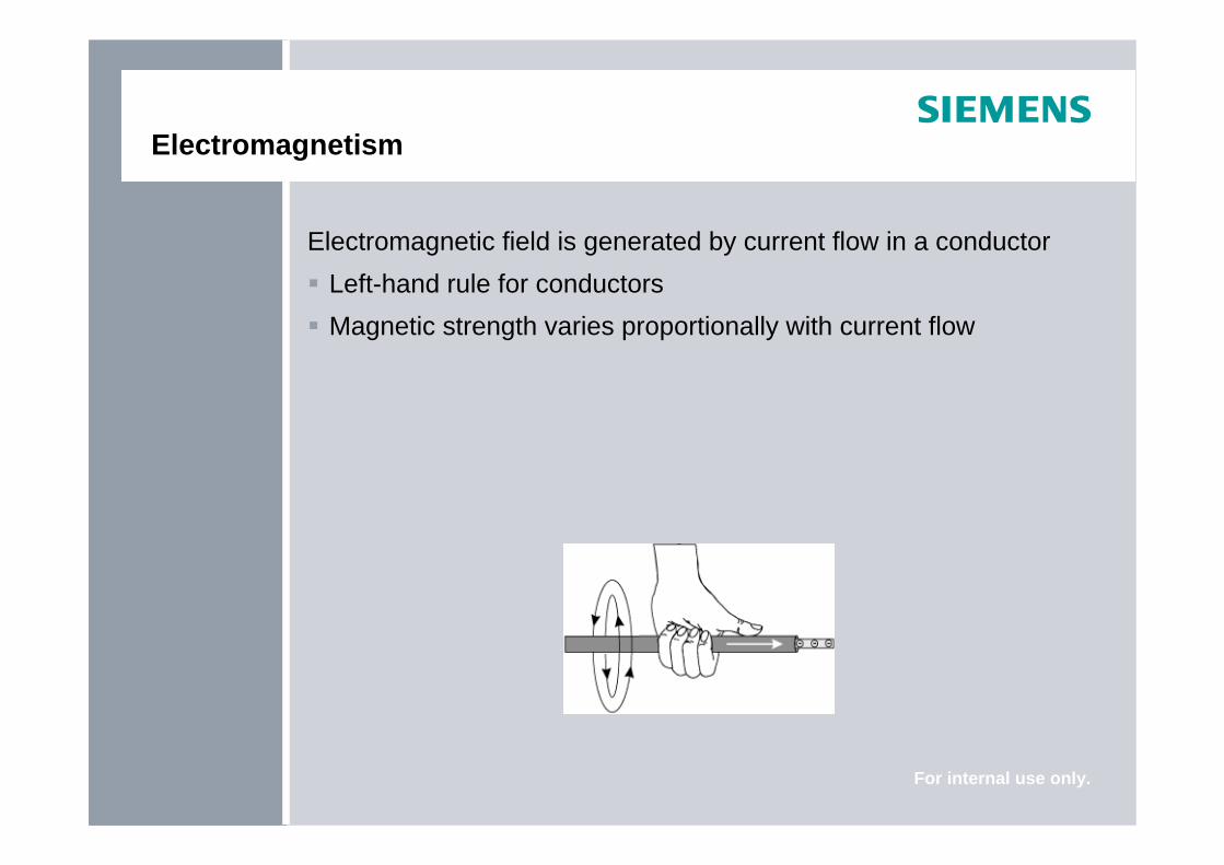
Electromagnetism
Electromagnetic field is generated by current flow in a conductorLeft-hand rule for conductorsMagnetic strength varies proportionally with current flow

For internal use only.
Electromagnetism
Electromagnet is made by winding a conductor into a coil around a core
Core is usually a soft ironCurrent passing through coil magnetizes coreLeft-hand rule for coilsMagnetic strength varies proportionally with the number of turns

For internal use only.
Motor Specifications

For internal use only.
Motor Specifications
HorsepowerHorsepower (US) = (T x rpm) / 5250kilowatts (Europe) = .746 x HPFractional: 1/3, ¼, ½, ¾Integral: 1-20,000 + Hp
VoltageElectromotive (emf) force required to make electricity flow through a conductor115, 200, 230, 460, 575, 2300, 4000, 4600, 6600, 7200V and 13.2 kV

For internal use only.
Motor Specifications
FrequencyLike a magnet the magnetic field of an electromagnet has a northand south poleWhen direction of current flow changes, polarity of electromagnet changesThe process repeats itself 60 or 50 times a second
AltitudeMotors suitable for 3300 ft ASL or 1000 mClass F Insulation suitable for 9900 ft ASL

For internal use only.
Motor Specifications
No. of Poles Synchronous Speed
2 3600/3000
4 1800/1500
6 1200/1000
8 900/750
10 720/600
# Pole = (120)Hz/Ns

For internal use only.
Motor Specifications
SlipRelative difference between speed of rotor and rotating magneticfieldNecessary to produce torque
% Slip =
% Slip =
% Slip = Ns-NrNs
x 100
1800-17651800
x 100
1.9%

For internal use only.
Motor Specifications
Service FactorA multiplier applied to the rated power1.0, 1.15 or 1.25
Motor DesignNEMA Design A, B, C, DStandard for motor performance
EfficiencyIndicates how much input AC energy is converted to output mechanical energy

For internal use only.
Motor Specifications
Insulation Class Class F Class HSlot Liner/Wedges and Coil Separator
100% fill polyester fiber-polyester film-polyester fiber laminate
Nomex laminate-polyester film-Nomex laminate
SleevesAcrylic coated glass impregnated with varnish
Flexible silicone rubber trated fiberglass
Tie Cord Heat shrinkable polyester Heat shrinkable polyesterVarnish 100% solids polyester resin 100% solids polyester resinLeads Cross linked polymer or Teflon Silicone Rubber or Teflon
Maximum Winding Temperature Rise °C1.0 SF 1.15 SF
A B F H A B F60 80 105 125 70 90 11540 deg C ambient, Resistance Method

For internal use only.
NEMA Motor Characteristics
NEMA Design A - not often used ( high LRA )NEMA Design B - most commonNEMA Design C - high torqueNEMA Design D - high torque and high slip
For internal use only.
NEMA Motor Characteristics
NEMA Design B Most commonThe relationship between speed and torque from moment of start until motor reaches full-load torque at rated speed is expressed in a Speed-torque curve

For internal use only.
Speed-torque Curve
Starting (Locked Rotor) TorqueAccelerating TorqueBreakdown TorqueFull Load Torque
For internal use only.
Motor Torque
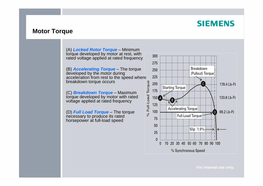
(A) Locked Rotor Torque – Minimum torque developed by motor at rest, with rated voltage applied at rated frequency
(B) Accelerating Torque – The torque developed by the motor during acceleration from rest to the speed where breakdown torque occurs
(C) Breakdown Torque – Maximum torque developed by motor with rated voltage applied at rated frequency
(D) Full Load Torque – The torque necessary to produce its rated horsepower at full-load speed

For internal use only.
Current
Locked-Rotor Current: starting current measured from supply line at rated voltage and frequency with the rotor at rest (600-650% for NEMA B)Full-Load Current: current measured from supply line at rated voltage, frequency and load with the rotor up to speed
For internal use only.
NEMA Motor Characteristics
NEMA Design A Higher LRA will yield NEMA Design AUsed for special load torque or inertia requirements
NEMA Design CStarting torque approximately 225%High inertia load applications (conveyors, plunger pumps)Single speed motors from 5-200 HP
For internal use only.
NEMA Motor Characteristics
NEMA Design D Starting torque approximately 280%Very high inertia load applications (punch presses, cranes, hoists)No true breakdown torqueAfter initial LRT is reached, torque decreases until FLT is reachedHigh slip (5-8% or 8-13%)

For internal use only.
Motor Construction
Three basic partsRotorStatorEnclosure
Enclosure
Stator
Rotor
For internal use only.
Stator Construction
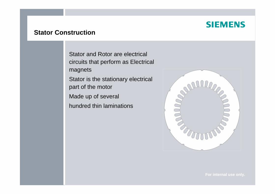
Stator and Rotor are electrical circuits that perform as Electrical magnetsStator is the stationary electrical part of the motorMade up of several hundred thin laminations

For internal use only.
Stator Construction
Stator laminations stacked together forming a hollow cylinderCoils of insulated wire inserted into stator core slots

For internal use only.
Stator Construction
Each grouping of coils, together with the steel core it surrounds form an electromagnetStator windings connected to power source

For internal use only.
Rotor Construction
The rotor is the rotating part of the electromagnet circuit
For internal use only.
Rotor Construction
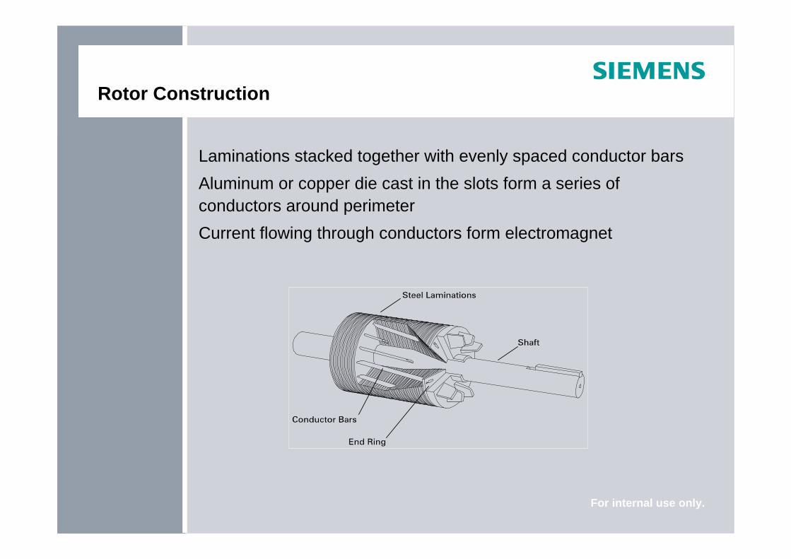
Laminations stacked together with evenly spaced conductor barsAluminum or copper die cast in the slots form a series of conductors around perimeterCurrent flowing through conductors form electromagnet

For internal use only.
Enclosures
Consists of Frame (Yoke) and two end brackets (bearing housings)Stator is mounted inside frameRotor fits inside stator
Slight air gapNo physical contact between stator and rotor

For internal use only.
Enclosures
Protects electrical and operating parts of motor from harmful environmental effects

For internal use only.
Enclosures
ODP: Open Drip ProofTEFC: Totally Enclosed Fan CooledTENV: Totally Enclosed Non-ventilatedTEAO: Totally Enclosed Air-overWP1/WP2: Weather Protected 1 and 2TEAAC: Totally Enclosed Air-to-Air CooledTEWAC: Totally Enclosed Water-to-Air Cooled

For internal use only.
Open Drip Proof (ODP)
Permit cooling air to flow through motorVent opening prevent liquids and solids from entering at from above angles up to 15º

For internal use only.
Totally Enclosed Non-ventilated
TENV restricts free exchange of air between inside and outside of motorAll heat dissipates by means of conduction Indoors and outdoorsMost TENV motors are fractional

For internal use only.
Totally Enclosed Fan Cooled
TEFC is similar to TENV with addition of a fanCan be used in dirty, moist, or mildly corrosive conditionsMore widely used for integral HP
Fan

For internal use only.
Explosion Proof (XP)
Similar in appearance to TEFCMost are Cast IronApplication subject to agencies such as NEC and UL

For internal use only.
Mounting
NEMA Dimensions- 143T14/4 = 3.5 (shaft height)3 = distance between bolt holes

For internal use only.
Mounting Positions
F-1StandardConduit box on left-hand side of motor when viewed from shaft end
F-2Conduit box on right-hand side of motor when viewed from shaft end

For internal use only.
Mounting Positions
Wall mounted“W” Prefix
Ceiling mounted“C” Prefix

For internal use only.
Flanges or Faces
For mounting directly to equipment
For internal use only.
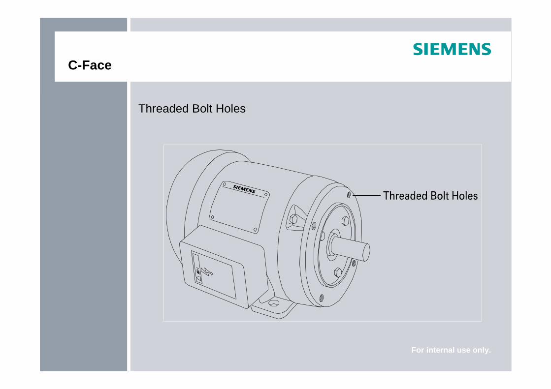
C-Face
Threaded Bolt Holes
For internal use only.
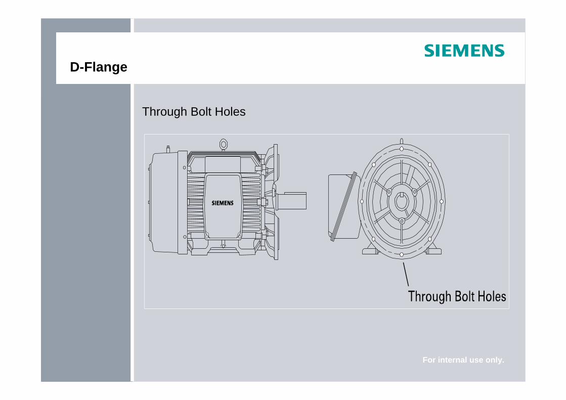
D-Flange
Through Bolt Holes

For internal use only.
Vertical Pump Motors
P Flange, Hollow ShaftNo longer offered by Siemens25 to 250 HP at 1800 RPM460 VAC
P Flange, Solid Shaft3 to 100 HP at 3600 RPM, 3 to 250 HP at 1200 and 1800 RPM

For internal use only.
Siemens Product Lines – New NEMA
Totally Enclosed Fan CooledGP100A, GP100SD10MS, SD100, SD100 IEEERGZVESD, RGZVILESD
Explosion Proof MotorsXP100XP100ID1

For internal use only.
Siemens Product Lines – ODP and Legacy Motors
Open Drip Proof (no longer available)DP10 RGE1, RGE, RG
Totally Enclosed Fan CooledRGZP, RGZESD,RGZEESD, RGZEESDX (841)
Totally Enclosed Fan Cooled, Explosion ProofRGZZESD
Definite Purpose MotorsRGZVESD, RGZVILESD, RGZESDI

For internal use only.
Siemens New NEMA Motor Nomenclature
GP = General PurposeA = Aluminum FrameIEEE = IEEE 84110 = EPACT EfficiencyNP = NEMA Premium (meets)
SD = Severe DutyXP = Explosion ProofBrake = Brake Duty Motor100 = NEMA Premium EfficiencyNPP = NEMA Premium Plus (exceeds)

For internal use only.
Siemens New NEMA Motor Nomenclature
Type DescriptionGP10 (OBSOLETE) TEFC, EPACTGP10A (OBSOLETE) TEFC, EPACT, AL frameGP10A Brake (OBSOLETE) TEFC, EPACT, AL frame, Brake dutyGP100 TEFC, NPGP100A TEFC, NP, AL frameSD10 (OBSOLETE) TEFC, SD, EPACTSD100 TEFC, SD, NPSD100 IEEE TEFC, SD, NP, IEEE 841XP100 TEFC, XP, SD, NPXP100 ID1 TEFC, XP, SD, NP, Group D

For internal use only.
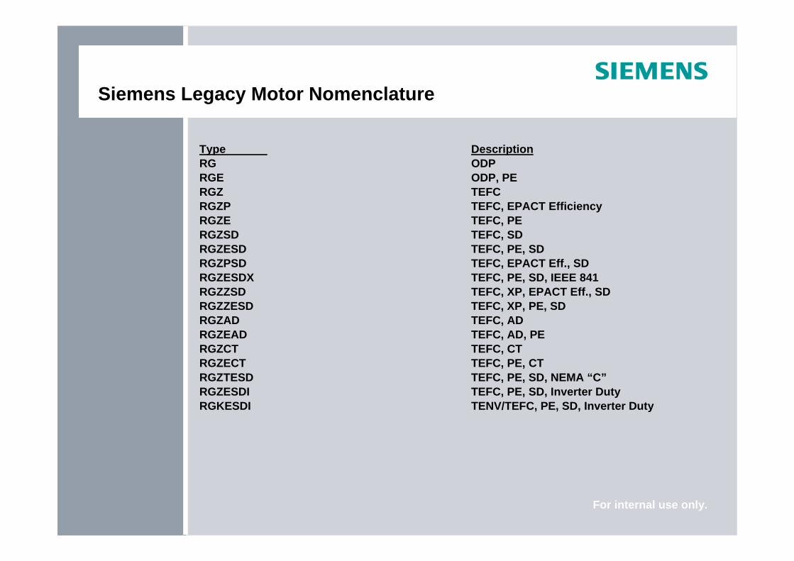
Siemens Legacy Motor Nomenclature
RG = ODPE = Premium EfficiencyEE = NEMA Premium EfficiencySD = Severe DutyZZ = Explosion Proof (XP)I = Inverter DutyF = C-flange, foot mountedCT = Cooling Tower
RGZ = TEFCP = EPACT EfficiencyX = IEEE 841AD = Automotive DutyT = NEMA Design CIL = In-Line Pump “P”V = C-flange, Round Body
For internal use only.
Siemens Legacy Motor Nomenclature
Type DescriptionRG ODPRGE ODP, PERGZ TEFCRGZP TEFC, EPACT EfficiencyRGZE TEFC, PERGZSD TEFC, SDRGZESD TEFC, PE, SDRGZPSD TEFC, EPACT Eff., SDRGZESDX TEFC, PE, SD, IEEE 841RGZZSD TEFC, XP, EPACT Eff., SDRGZZESD TEFC, XP, PE, SDRGZAD TEFC, ADRGZEAD TEFC, AD, PERGZCT TEFC, CTRGZECT TEFC, PE, CTRGZTESD TEFC, PE, SD, NEMA “C”RGZESDI TEFC, PE, SD, Inverter DutyRGKESDI TENV/TEFC, PE, SD, Inverter Duty

For internal use only.
Questions


