AC WLAN Product Family Operating instructions (applicable to firmware versions 2.x to 5.x) GB • Factory settings IP address range 192.168.0.xxx IP access http://192.168.0.5 Subnet address 255.255.255.0 SSID Rutenbeck Password Web interface admin WLAN password wireless123 • Your preferences Please note and keep ! IP access ........................................... Subnet address ........................................... SSID ........................................... Password web interface ........................................... WLAN password ........................................... MAC address (Rear side / label) ........................................... Technical Support +49 2355 82-111 [email protected]Commercial Support +49 2355 82-137 [email protected]
Transcript
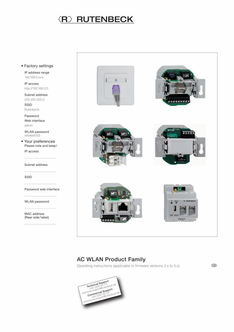
AC WLAN Product FamilyOperating instructions (applicable to firmware versions 2.x to 5.x) GB
Product spectrum ........................................................................................ 5 Distinction of AC WLAN versions without or with USB .................................... 5 General ....................................................................................................... 6 Documentation / instructions ......................................................................... 7 License notices ........................................................................................... 7 - License information .................................................................................... 7 - Availability of the source codes ................................................................... 7 Installation / assembly of the AC WLAN (flush-mounting version) ...................... 7 IP address assignment ................................................................................. 7 Settings ....................................................................................................... 8 - WLAN settings .......................................................................................... 8 - Roaming settings ....................................................................................... 8 Basic information on interfaces ..................................................................... 8 System prerequisites .................................................................................... 9 User interface of the web interface ................................................................ 9 Data protection ............................................................................................ 9
Configuration
Initial configuration ........................................................................................ 10 Individual configuration ................................................................................. 10 - Change the password for the web interface ................................................ 11 - Change the password for WLAN ................................................................ 11 - Changing the SSID .................................................................................... 12 - Changing the device name ........................................................................ 12 - Changing the time zone and language ........................................................ 12 Status information ........................................................................................ 13 Overview in the network ............................................................................... 13 Backup / software update ............................................................................. 14 - Download backup ..................................................................................... 14 - Restore backup ......................................................................................... 14 - Reset delivery status .................................................................................. 15 - Flash new firmware image .......................................................................... 15 Logout ........................................................................................................ 16 Restart ........................................................................................................ 16 Meaning of LED ........................................................................................... 16 Reset .......................................................................................................... 16 Operating modes ......................................................................................... 18 - Notes on the graphical representation ......................................................... 18
Examples 1 to 14 – graphic representations and detailed descriptions
General information about the examples ........................................................ 19
AC WLAN without USB 1. Access point to existing data socket, front feed via patch cable .................. 20 2. Access point on the router, infeed via fixed connection ............................... 20 3. Multiple access points on the switch (star-shaped, fixed connection) ........... 21 4. Bridge ..................................................................................................... 22 5. Repeater function (RELAYED) – WLAN Range extension ............................. 23 - Set up repeater function ......................................................................... 25 6. Multiple repeating with roaming – free movement in the WLAN without logging in ..................................................................................... 27 7. Repeating / forwarding via permanent connection – free movement in the WLAN without logging in ................................................................. 28
AC WLAN with PoE 9. Cabling via PoE switch (e.g. Rutenbeck SR 10 GTX B PoE ......................... 31
AC WLAN with USB 10. Network access to the USB interface of various devices .......................... 32 11. USB printer activation via LAN / WLAN ..................................................... 32 - Access for Apple devices to the USB interface of the AC WLAN via ‘File browser’ app .............................................................................. 33 - Access to a USB printer via operating system or app ............................... 35 - General ............................................................................................... 35 - Direct activation (Win) ........................................................................... 35 - Direct control (Mac, HP Officejet printer as an example) ......................... 36 - Direct control (Linux, HP Deskjet printer as an example) ......................... 36 - Control USB printers with mobile devices via WLAN ................................ 37 - General ............................................................................................... 37 - App for iOS ......................................................................................... 37 - App for android .................................................................................... 37 12. Router-independent internet access via LTE stick ..................................... 38 - Set up router-independent Internet access via LTE stick .......................... 38 13. Connection of a Smart TV without an own WLAN interface ....................... 40 14. Mobile hotspot on the smartphone .......................................................... 41
Advanced functions
Remote control (possible from Firmware 4.x) .................................................. 42 Timer function for LAN / WLAN ...................................................................... 43 - General information about enabling and disabling the WLAN ........................ 43 - Set up timer function .................................................................................. 43 Control AC WLAN via UDP ........................................................................... 45 Expert diagrams .......................................................................................... 46 Network diagnostics .................................................................................... 47 Command Reference - Detail Settings .......................................................... 48 - Status ....................................................................................................... 48 - System ..................................................................................................... 48 - Network .................................................................................................... 50 - Set up VLAN (port-based) ........................................................................ 50
Annex
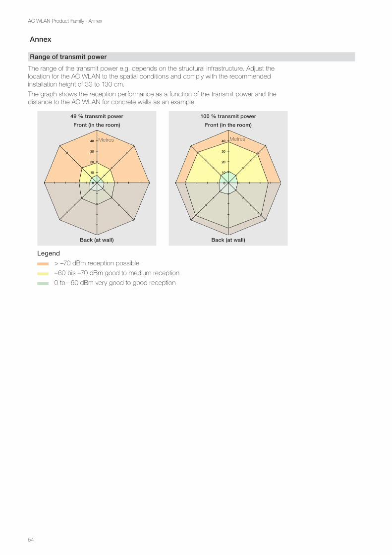
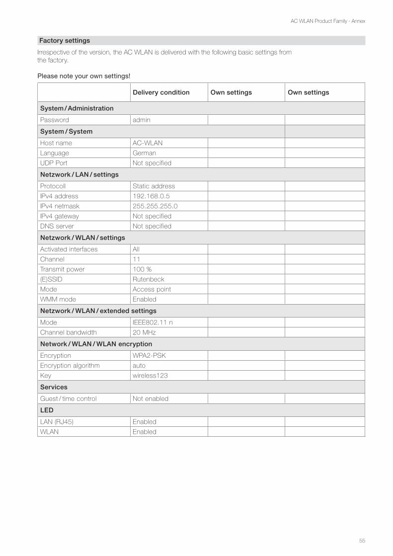
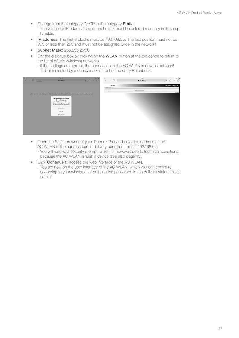
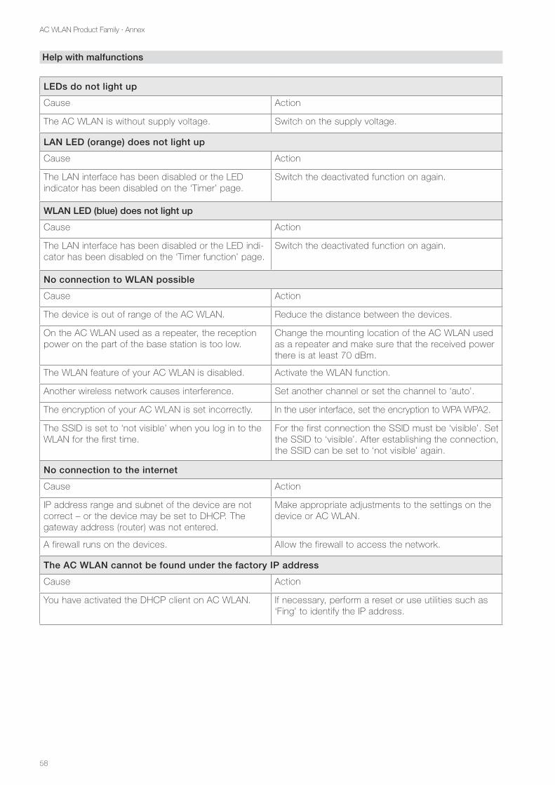
Range of transmit power .............................................................................. 54 Factory settings ........................................................................................... 55 Adjustments when accessing the AC WLAN through Apple mobile devices .... 56 Help with malfunctions ................................................................................. 58 Glossary ...................................................................................................... 59 Notes .......................................................................................................... 61 Address ...................................................................................................... 62
5
AC WLAN Product Family · Introduction
Introduction
Product spectrum
The product range of AC WLAN is constantly expanding. Currently the following devices are available. New developments can be found at rutenbeck.de
Flush-mounted variants:
• AC WLAN Up rw (Item No. 226 104 10)
• AC WLAN UAE Up rw (Item No. 226 104 030)
• AC WLAN POF / UAE 1xUp rw 2.2 mm (Item No. 226 104 050)
• Voltage supply SVR 52 V PoE+ (Item No. 235 103 04)
Distinction of AC WLAN versions without or with USB
• Left image section: Use of the AC WLAN without USB: Internet access via router, wired connection to AC WLAN, e.g. no print server functionality
• Right image section: Use of the AC WLAN with USB: Connection of external USB data carrier or router function via separate LTE stick, printer control from e.g. smartphone via print server
Router
AC-WLAN without
USBPrinter
Internet
USB stick, NAS or
internet via LTE stick
iPhone
Laptop
Laptop
USB versions
The AC WLAN ver-sions with USB port come with a different firmware version (e.g. 5.x.x.1.x), which is to be considered for updates.
In contrast to the standard application (e.g. 5.0.x), only this application that belongs to USB ver-sions offers functionali-ties such as: e.g. print server (see below).
6
AC WLAN Product Family · Introduction
General
The AC WLAN offers a contemporary alternative to meet the requirements of modern net-work infrastructures according to DIN 18015-2 and RAL-RG 678, without sacrificing the flexible use of modern, mobile technologies such as tablet PCs or laptops and restricting the wireless data rates.
In addition, the AC WLAN works like a normal data outlet with RJ45 outlet for a conventional data terminal (data rate 100 Mbit/s). Power is supplied directly via 230 V on the back, via separate power supplies (REG devices) or in the case of special versions via PoE.
The AC WLAN is connected to the internal data network via classic copper data cable or via polymer optical fibres (POF).
The WLAN range can be adapted to the conditions prevailing in the room and limited to the room. This results in powerful room radio cells, which ensure maximum wireless band-width within the room and work with low power consumption and low radiation. Due to its low energy requirement and thus low radio emission, delimitation problems under individual access points and over-coupling of the WLAN areas or losses in the data rates are largely avoided.
The AC WLAN can also be controlled directly via UDP and has extensive programming, time switching and additional protocol functions (see page 45).
In principle, the following functional principles (1.-3.) / application options (4.-8.) can be distinguished:
AC WLAN
1. Access point: AC WLAN as access point, bidirectional communication of all WLAN terminals via the Cu/POF interface to the router / internet
2. Client: Devices without a WLAN adapter (e.g. TV box) are becoming ‘WLAN-capable’, bidirectional communication
3. Bridge: Connection of two network segments via two AC WLAN, bidirectional communication
4. Repeater: Range increase of a router or/and an AC WLAN through another AC WLAN
5. Roaming: Free movement with mobile WLAN devices in all rooms, secure identification of network IDs in all rooms (identical SSID)
6. Guest: Access to the Internet is possible via guest access, access to the in-house network is not possible!
7. Time-controlled LAN/WLAN: The WLAN as well as the front socket can be switched on and off in a time-controlled manner.
8. Central programming: Changes to the most important network configurations of all AC WLANs via just one logon to the network
AC WLAN POE
- PoE data exchange: Connection / operation of additional class 2 / 6.49 W PoE terminals (e.g. IP cameras) – the necessary voltage is provided by means of a PoE injector or PoE switch.
AC WLAN UAE / USB version
- USB data exchange: Provision of content from USB devices on the internal network.
- USB network printer: Provision of a USB printer as a network printer.
- Router function: By means of an additional LTE / GSM stick, the AC WLAN assumes the router function in the network.
Do not use the AC WLAN for any other purpose and use it indoors only.
7
AC WLAN Product Family · Introduction
Documentation / instructions
The AC WLAN is accompanied by several instructions / notes for the following areas:
- License notice (GNU)
- Installation instructions / quick guides – in the relevant device scope of delivery
- Operating instructions – in the download area under www.rutenbeck.de
• Electrical voltage! Danger to life and fire hazard possible by electrical voltage of 230 V. Work on the 230 V network may only be carried out by qualified electricians!
Before using the AC WLAN, it is essential to observe the following infor-mation in order to avoid damage of any kind or functional restrictions.
License notices
Parts of the firmware are subject to the GNU General Public License.
License information
This product contains third-party software under the terms of the GNU General Public License. You may modify or distribute this free software under the terms of the GNU General Public License.
Availability of the source codes
Upon request, we will send you the entire source code of the GNU General Public License licensed software - including all scripts to control the compilation and installation of the driv-ers. Full details of the license can be found in a separate document.
Installation / assembly of the AC WLAN (flush-mounting version)
• For installation / connection, only use connection / junction boxes or multiple sockets (e.g. electronic boxes, Kaiser Elektro) in accordance with DIN 49073.
• Do not place metal objects (shelves, etc.) directly in front of the installation posi-tion of the AC WLAN, as this may affect the range.
• Choose a mounting height between 0.3 to 1.3 m in the wall. Do not mount the AC WLAN on the ceiling as the built-in antennas are not opti-mized for this purpose.
• When used as a repeater, the signal strength of the signal to be amplified at the installation site must be ≥ 70 dBm.
• Only install the AC WLAN indoors.
• In case of malfunctions, do not open the housing of the AC WLAN – if necessary, contact our technical service.
IP address assignment
- All AC WLANs of a network must be in the same IP address range as the corresponding router. These are the first three number blocks of the IP address: (192.168.xxx). Likewise, the subnet address must be the same (usually 255.255.255.0).
- There must be no duplicate IP addresses within a network!
• Put the devices in operation one after the other! Switch off unprogrammed devices to avoid IP address collisions! From version 4.0.0.0, the central ‘remote control’ can be used for central program-ming. This allows installation without prior programming. In any case, note down the MAC address of the AC WLAN in connection with the installation location in order to be able to clearly identify it during central programming later!
For system devices within the network such as the AC WLAN, fixed (static) IP addresses assigned to the automatic assignment by the router (DHCP) are preferable ! In the event of a malfunction, you can keep track of and access the devices and increase the reliability of your system !
Note:
The AC WLAN is the world’s first WLAN access point in a standard installation box, and also fits all design programs of well-known switch manufacturers.
Important!
Observe the notes in the installation instruc-tions / quick guides of the respective devices.
8
AC WLAN Product Family · Introduction
• Document the IP addresses, the associated MAC addresses (rating plate and label), the installation location, the firmware version as well as the associated passwords and access data for a possible service case (see also page 55 or title page).
Settings
WLAN settings
The less WLAN devices can ‘hear’ each other in the WLAN network, the higher the perfor-mance. If there is a long distance between WLAN devices or if an older WLAN device with low bandwidth (e.g. in accordance with IEEE 802.11-b) is connected to the AC WLAN, the transmission rate is automatically adapted to the performance of this application. Higher data rates will then not be available for closer or more powerful devices.
• Choose a channel that is hardly used in its environment.
• If necessary, adjust the channel spacing of the devices (a distance of four channels is optimal).
• If necessary, adjust the transmit power and, with this, the sensitivity of the AC WLAN to avoid overlapping (as few as necessary).
• Look for identical encryption algorithms on ‘all’ WLAN devices. WPA is out of date, no longer safe and no longer allowed for new equipment!
The operating bandwidth can be switched internally from 20 to 40 MHz. This doubles the data rate. For physical reasons, however, the range is reduced to half, so that this setting is suitable only for short distances.
Roaming settings (see examples on page 26 et seq.)
Easy roaming can be ensured with the same SSID of all access points / routers in the net-work, as well as with different SSIDs. After a single sign on mobile devices to an access point, the devices remember the credentials and automatically switch to the strongest signal in the environment when the signal is weak.
This switching threshold can usually not be changed in the devices or depends on the manufacturer / operating system – changeover usually occurs only with a very weak signal (-70 dB).
With several SSIDs, it is easier to check, in the case of transmission problems, if the device is really logged in to the nearest access point. A performance improvement may be achieved by selecting a stronger access point.
Basic information on interfaces
This manual often mentions the use or the specification of interfaces. Basically, two types are distinguished (see figure below):
- External interfaces, e.g. front socket (RJ45)) on the hardware side
- Internal functional interfaces, e.g. additional transceiver units for guest access or repeater function
WLAN
RJ45
Cu/PoF
Client (RELAYED)
Guest etc.
Interfaces on the hardware side
Function interfaces
AC WLAN
Note:
The described facts are due to physical / technical conditions and not a feature of the AC WLAN.
Note:
With SSID, it is assumed that within a network there is only one access point that maps the router. If there are several SSIDs within a network, which may then be the same, this is called ESSID.
For simplicity’s sake, these instructions always refer to SSID.
9
AC WLAN Product Family · Introduction
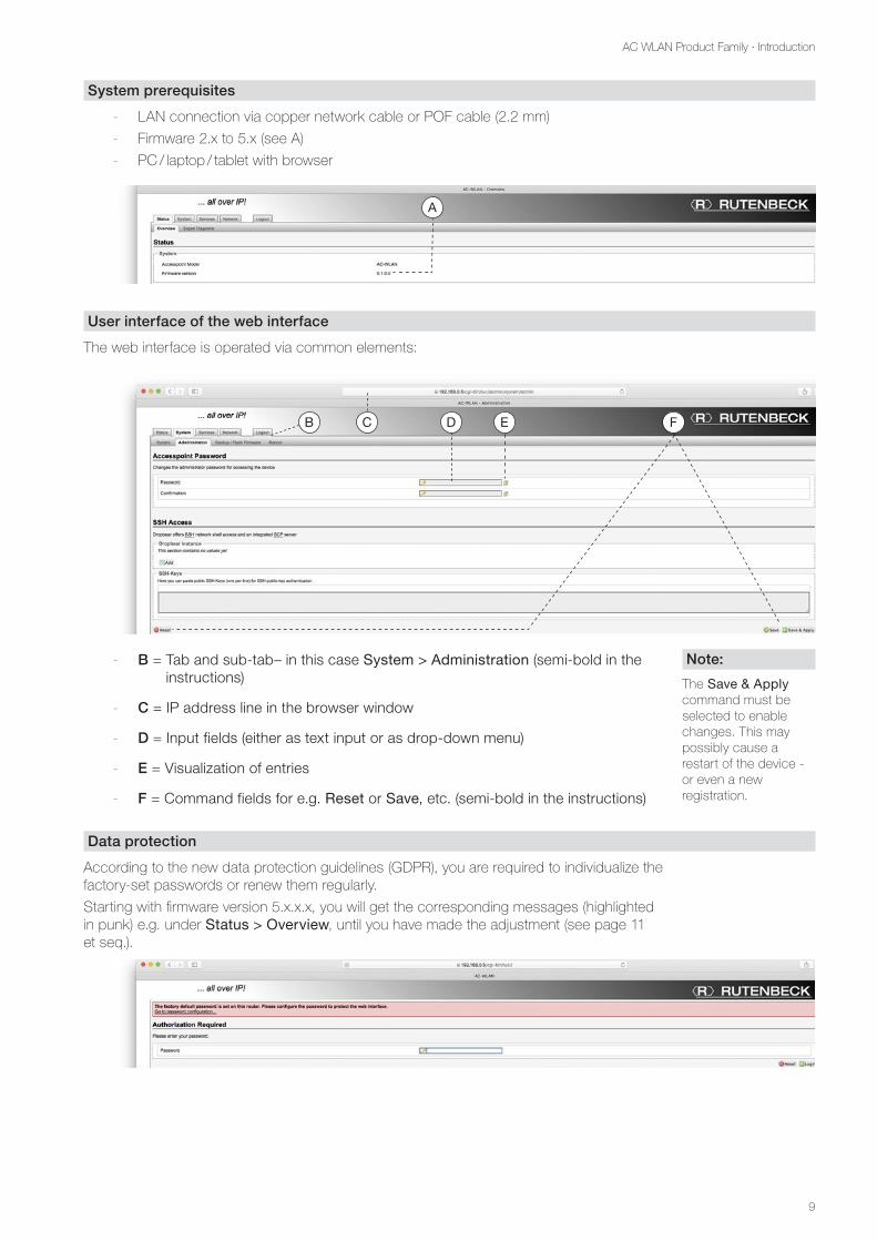
System prerequisites
- LAN connection via copper network cable or POF cable (2.2 mm)
- Firmware 2.x to 5.x (see A)
- PC / laptop / tablet with browser
User interface of the web interface
The web interface is operated via common elements:
- B = Tab and sub-tab– in this case System > Administration (semi-bold in the instructions)
- C = IP address line in the browser window
- D = Input fields (either as text input or as drop-down menu)
- E = Visualization of entries
- F = Command fields for e.g. Reset or Save, etc. (semi-bold in the instructions)
Data protection
According to the new data protection guidelines (GDPR), you are required to individualize the factory-set passwords or renew them regularly.
Starting with firmware version 5.x.x.x, you will get the corresponding messages (highlighted in punk) e.g. under Status > Overview, until you have made the adjustment (see page 11 et seq.).
Note:
The Save & Apply command must be selected to enable changes. This may possibly cause a restart of the device - or even a new registration.
DB C E F
A
10
AC WLAN Product Family · Configuration
Configuration
Initial configuration
Make sure the device is properly connected. You will find information in the associated installation instructions.
In order to avoid connection interruptions after the changing of settings, it is recommended to carry out the initial configuration via one of the LAN interfaces of the device – e.g. via the front socket.
• Use a patch cable to connect the LAN interface of your PC / tablet with that of the AC WLAN.
The address of the programming PC / tablet must be in the range 192.168.0.xxx (x ≥ 0 ≤ 255, x ≠ 5!), the subnet mask must be set to 255.255.255.0.
• Start your browser (e.g. Chrome, Edge, Firefox, Safari, etc.) and enter https://192.168.0.5 in the address bar. - The communication between your browser and the AC WLAN
is encrypted (https://).
For websites, a security certificate is usually exchanged prior to communication, and both parties must be aware of this. AC WLAN is a device, not a website – no certificate is provided.
If the corresponding browser messages (e.g. Chrome: ‘This is not a secure connection’) appear, you can switch to Advanced Mode and allow the connection. To avoid having to do this step each time, you should add an exception in the browser and download a certificate that is then provided.
• To access the web interface, enter the appropriate password admin (as delivered state).
• Log in by clicking on the green icon at the bottom right.
If the initial configuration can only be done via WLAN, first search the AC WLAN via the radio interface of the device intended for commissioning (tablet, PC or similar). The AC WLAN logs on to the network with the SSID Rutenbeck. The WLAN password is wireless123 when delivered. Possibly, the IP address of the tablet / PC must be adjusted manually beforehand ! (192.168.0.xxx, Subnet 255.255.255.0) – see e.g. page 56.
Individual configuration
When delivered, the AC WLAN is provided with factory settings (see page 55) and ready for operation.
Via the web interface, you can configure the AC WLAN and thus adapt it to your needs (e.g. the language). Access is possible via patch cable, fixed connection or WLAN.
We recommend adapting the following factory settings:
- Password of web interface: admin (see page 11)
- Password of WLAN: wireless123 (see page 11)
- SSID: Rutenbeck (see page 12)
- Device name: AC WLAN (see page 12)
- Time zone: Europe / Berlin (see page 12)
- Language: German (see page 12)
Password assign.
For a change of pass-words, SSID etc., use only numbers and let-ters (without spaces).
Pop-up blocker
If the blocking of pop-ups is enabled in the browser, you must explicitly allow access beforehand via the cor-responding dialogue.
Note:
For information on remote access via SSH, see page 49.
11
AC WLAN Product Family · Configuration
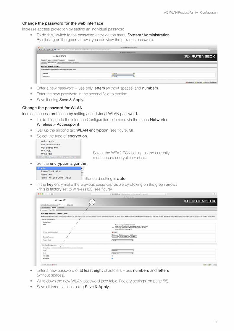
Change the password for the web interface
Increase access protection by setting an individual password.
• To do this, switch to the password entry via the menu System / Administration. By clicking on the green arrows, you can view the previous password.
• Enter a new password – use only letters (without spaces) and numbers.
• Enter the new password in the second field to confirm.
• Save it using Save & Apply.
Change the password for WLAN
Increase access protection by setting an individual WLAN password.
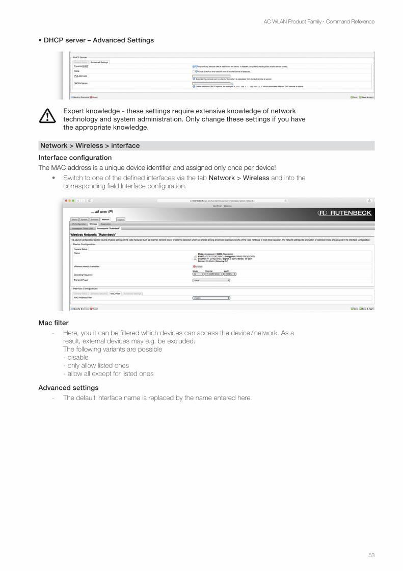
• To do this, go to the Interface Configuration submenu via the menu Network> Wireless > Accesspoint.
• Call up the second tab WLAN encryption (see figure, G).
• Select the type of encryption.
Select the WPA2-PSK setting as the currently most secure encryption variant..
• Set the encryption algorithm.
Standard setting is auto
• In the key entry make the previous password visible by clicking on the green arrows - this is factory set to wireless123 (see figure).
• Enter a new password of at least eight characters – use numbers and letters (without spaces).
• Write down the new WLAN password (see table ‘Factory settings’ on page 55).
• Save all three settings using Save & Apply.
G
12
AC WLAN Product Family · Configuration
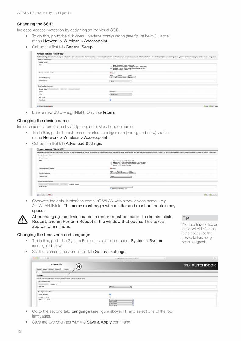
Changing the SSID
Increase access protection by assigning an individual SSID.
• To do this, go to the sub-menu Interface configuration (see figure below) via the menu Network > Wireless > Accesspoint.
• Call up the first tab General Setup.
• Enter a new SSID – e.g. INtakt. Only use letters.
Changing the device name
Increase access protection by assigning an individual device name.
• To do this, go to the sub-menu Interface configuration (see figure below) via the menu Network > Wireless > Accesspoint.
• Call up the first tab Advanced Settings.
• Overwrite the default interface name AC WLAN with a new device name – e.g. AC-WLAN-INtakt. The name must begin with a letter and must not contain any spaces.
After changing the device name, a restart must be made. To do this, click Restart, and on Perform Reboot in the window that opens. This takes approx. one minute.
Changing the time zone and language
• To do this, go to the System Properties sub-menu under System > System (see figure below).
• Set the desired time zone in the tab General settings.
• Go to the second tab, Language (see figure above, H), and select one of the four languages.
• Save the two changes with the Save & Apply command.
Tip
You also have to log on to the WLAN after the restart because the new data has not yet been assigned.
H
13
AC WLAN Product Family · Configuration
Status information
Status > Overview shows the current values of the system and which devices are connect-ed to the AC WLAN.
The System sub-item displays the following information:
- Mode: The standard setting is Access point
- Firmware version: The current version is 5.x.x.x For information on updates see page 14 et seq.
In the Wireless sub-item, further details are displayed – especially
- the signal quality (87 % in the figure) and the channel (i.e. channel 11).
In the sub-item Registered stations, you will find the following details
• about SSID, MAC and IP address (also see page 52)
• about useful and interference signal (noise)
• about transfer rates and channel bandwidth (20 / 40 MHz)
A signal power of 20 % should not be underrun to ensure secure data transmission to the relevant device.
Overview in the network
For a further overview, all devices are listed in Network > IP Configuration under the inter-faces sub-item.
The following actions are available to you:
• Connect: enables the relevant interface
• Stop: disables the relevant interface
• Edit: allows the configuration of the relevant interface
• Delete: deletes the relevant interface
• Add new interface: adds another interface
The interface symbols in the left field at the bottom ( I ) mean:
- Copper / POF (cable connection)
- Front connection (RJ45 front socket)
- WLAN
If one of the symbols is missing, the corresponding interface is not available or deleted.
Note:
Due to the operating system, the first station may be displayed twi-ce. This is not an error!
Note:
The functionality of the Expert Diagrams is described on page 46.
Note:
The changes made here can lead to exten-sive changes in the device function and should only be perfor-med if you are certain! After modification, the device may not be accessible via this interface!
I
14
AC WLAN Product Family · Configuration
• Under Network > Wireless, the overview can be specified further.
There are two different types of action available:
• Scan: The network is scanned again for existing interfaces.
• Add: New interfaces can be added.
• Disable: The interface is disabled.
• Edit: Allows the configuration of the relevant interface.
• Remove: Deletes the interface – this step cannot be undone! There must be at least one interface – otherwise you will lose access to the device.
Backup / software update
For safety reasons, you can save your individual settings on a PC, restore them from there or reset them to the factory settings.
Download backup
• To do this, go to System > Backup / Software Update under Actions > Backup / Restore (see figure below).
• Download a backup by clicking on Generate archive (K).
• The backup is stored as a compressed file with the suffix .bin in the download folder of your PC. - The file name will be assigned automatically.
• If necessary, rename the file and save it to a location of your choice.
Restore backup
Now proceed as follows:
• To do this, go to the menu item System > Backup / Software Update to the Actions sub-item as described above or shown.
• Click on Select file (J).
• Select the desired backup with the suffix .bin.
• Download the backup to the AC WLAN by clicking on Restore backup. - The process must not be interrupted and takes about 2 to 3 minutes.
‘REMOVED‘
After a backup restore, all WLAN passwords must be re-assigned. Otherwise, the WLAN will remain inactive.
Tip
If you want to install several AC WLANs with the same configu-ration, you can save the backup of one device and load it into other devices.
Note:
The presentation may differ slightly if you are logged in via WLAN (not via the front socket).
K LJ
15
AC WLAN Product Family · Configuration
Reset delivery status
A reset resets the AC WLAN to the delivery status of the last firmware installed. A reset can be made as follows:
- with the aid of a Reset magnet (order No. 293 749) – hardware-dependent (see page 16 et seq.)
- via web browser (on the software side for all devices)
When resetting via web browser, proceed as follows:
• To do this, go to the menu item System > Backup / Software Update to the sub-item Actions as described or shown above.
If you reset the configuration in the following, all individual definitions regarding passwords, language settings etc. will be lost !
• Click on Perform reset (L). - This process must not be interrupted and takes about 2 to 3 minutes.
Flash new firmware image
The latest firmware can be downloaded from our website in the download area. Now pro-ceed as follows:
• Save the file on your PC.
• Change to the submenu Actions > Flash new firmware image via the menu System > Backup / Software Update as shown.
• Click on Select file and select the file.
Important:
- With a ‘large’ software update (e.g. from 4.x.x.x to 5.x.x.x), no settings can be applied. Be sure to disable the Keep configuration option.
- With a ‘small’ software update within the respective ‘version’ (e.g. 4.0.0.0 and 4.0.0.1), however, all settings in the device can be retained after the update, provided that the check mark ‘Retain configuration’ was set.
• If you want to keep the current configuration, confirm this.
• Click on Flash image (M). - Up to version 5.0.0.0, all variants are consistently backwards compatible.
• Click on Continue in the following dialogue.
- The process must not be interrupted and takes about 2 to 3 minutes.
• After successfully updating the firmware, you must log in again.
Tip
The file has the suffix .bin and is named e.g. for version 5.0: acw-rk-5000.bin
M
16
AC WLAN Product Family · Configuration
Logout
• By clicking on the Logout tab on the far right, you leave the user interface of the AC WLAN. - You must first save the settings you have made for acceptance. - In order to make further changes (at a later date), you must log in again with your
password.
Restart
• To do this, go to the relevant sub-item via System > Reboot.
• Click the Reboot command button.
A reboot will accomplish the following:
- New connection to the router / internet
- New connection to the registered devices
Meaning of LED
The state of the LED can be used to understand the start-up and for detailed error analysis. The following LED is available:
LED (RJ45 socket)
- blue = WLAN
- orange = LAN
- green =
External Ethernet-port (Cu data cable / POF)
- LED blue = WLAN
- LED orange = LAN
- LED purple (blue + orange) = WLAN / LAN active
- Flashing = data traffic
Reset
A reset resets the AC WLAN to the delivery status of the last firmware installed.
A reset can be made as follows:
- by means of the Reset magnet accessory outside of the device (Order No. 293 749)
- by means of web browser via System > Reboot
For all device versions with illuminated socket, a reset must be made exter-nally by means of a reset magnet.
Performing a reset while preserving the settings
Depending on the device variant, the reed contact may be located at a different point on the device. Please observe the associated installation instructions.
Important
Please observe the instructions accom-panying the reset magnet to avoid per-sonal injury and damage to property.
Note:
The LED may have been switched off via the user interface of the AC WLAN and would have to be swit-ched on again for the described functionality - e.g. Services > Remote Control
17
AC WLAN Product Family · Configuration
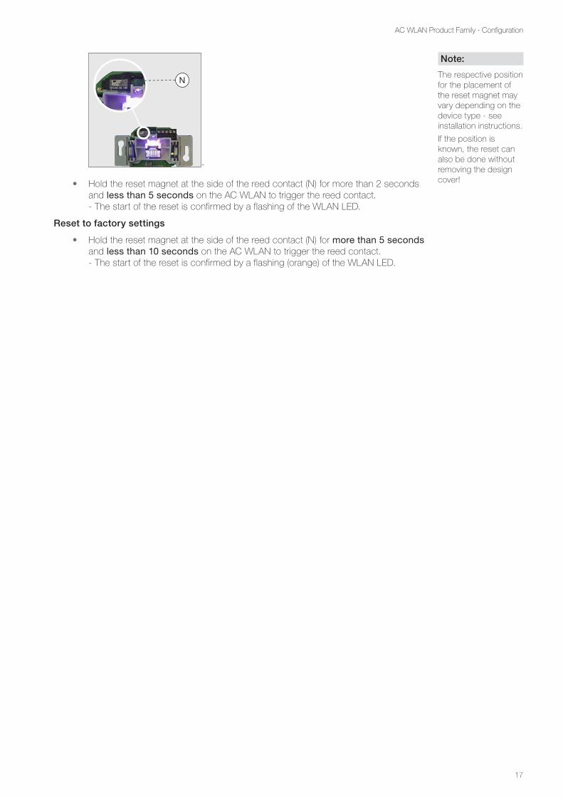
N
-
• Hold the reset magnet at the side of the reed contact (N) for more than 2 seconds and less than 5 seconds on the AC WLAN to trigger the reed contact. - The start of the reset is confirmed by a flashing of the WLAN LED.
Reset to factory settings
• Hold the reset magnet at the side of the reed contact (N) for more than 5 seconds and less than 10 seconds on the AC WLAN to trigger the reed contact. - The start of the reset is confirmed by a flashing (orange) of the WLAN LED.
Note:
The respective position for the placement of the reset magnet may vary depending on the device type - see installation instructions.
If the position is known, the reset can also be done without removing the design cover!
18
AC WLAN Product Family · Configuration
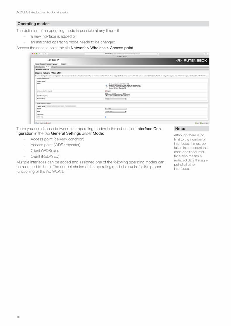
Operating modes
The definition of an operating mode is possible at any time – if
- a new interface is added or
- an assigned operating mode needs to be changed.
Access the access point tab via Network > Wireless > Access point.
There you can choose between four operating modes in the subsection Interface Con-figuration in the tab General Settings under Mode:
- Access point (delivery condition)
- Access point (WDS / repeater)
- Client (WDS) and
- Client (RELAYED)
Multiple interfaces can be added and assigned one of the following operating modes can be assigned to them. The correct choice of the operating mode is crucial for the proper functioning of the AC WLAN.
Note:
Although there is no limit to the number of interfaces, it must be taken into account that each additional inter-face also means a reduced data through-put of all other interfaces.
19
AC WLAN Product Family · Examples AC WLAN without USB
Examples AC WLAN without USB
General information about the examples
The AC WLAN acts as an interface between WLAN, permanently connected data devices and cabling in the network. Depending on the operating mode, different operating parame-ters must be set.
The following descriptions assume manual assignment of the IP addresses of the devices. When using a router with a DHCP server function, IP address assignment in the network takes place automatically.
Please note that the automatically assigned IP address of the AC WLAN or other devices is not known to you and further programming /changes to the settings could therefore be difficult.
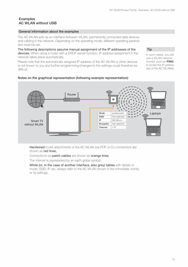
Notes on the graphical representation (following example representation):
Router
Laptops
Smart TVwithout WLAN
Mode access point
SSID free selection
IP 192.168.x.x
Encryption free selection
Channel 1–13
- Hardwired router attachments of the AC WLAN (via POF or Cu connection) are shown as red lines,
- Connections via patch cables are shown as orange lines.
- The internet is represented by an earth globe symbol.
- White (or, in the case of another interface, also grey) tables with details of mode, SSID, IP, etc. always refer to the AC WLAN shown in the immediate vicinity or its settings.
Tip
In such cases, you will use a WLAN network monitor such as FING to locate the IP addres-ses of the AC WLAN(s).
20
AC WLAN Product Family · Examples AC WLAN without USB
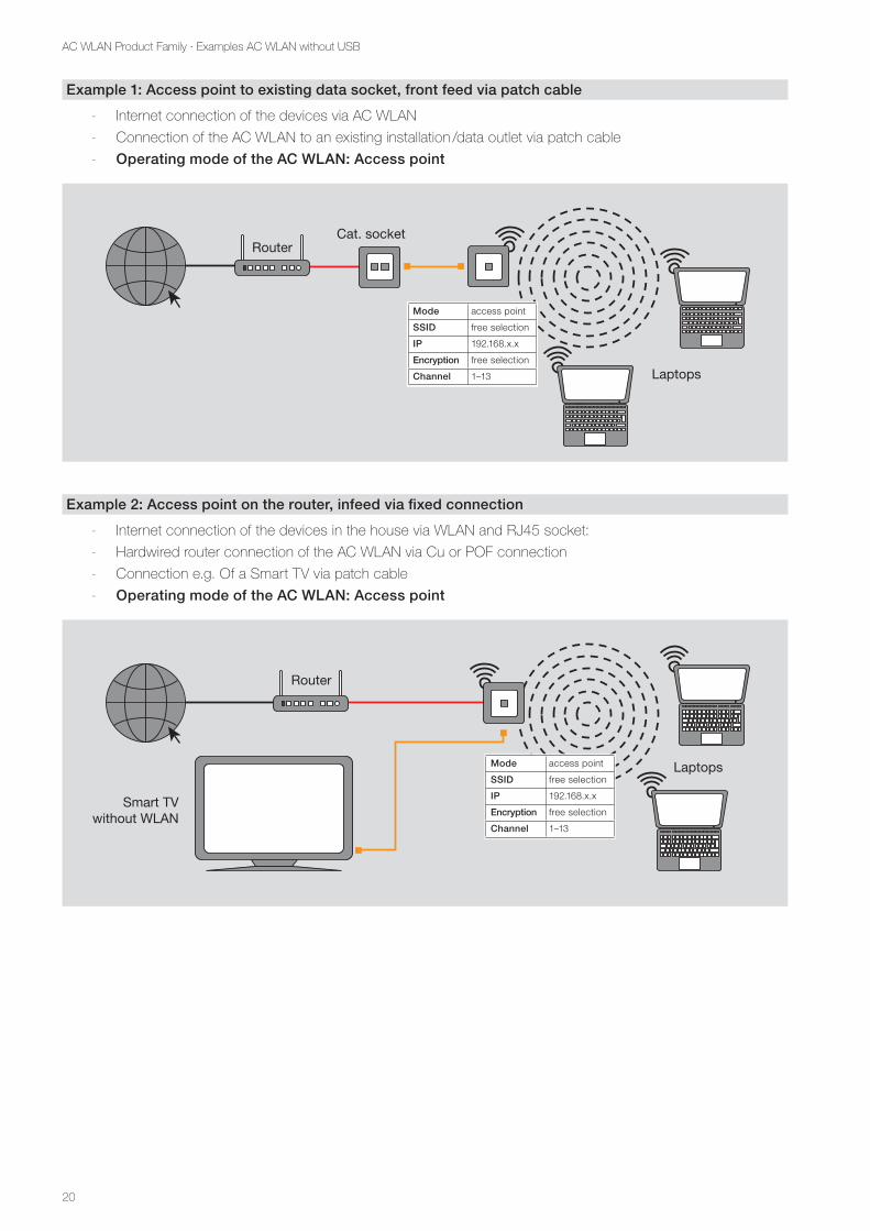
Example 1: Access point to existing data socket, front feed via patch cable
- Internet connection of the devices via AC WLAN
- Connection of the AC WLAN to an existing installation /data outlet via patch cable
- Operating mode of the AC WLAN: Access point
Router
Laptops
Cat. socket
Mode access point
SSID free selection
IP 192.168.x.x
Encryption free selection
Channel 1–13
Example 2: Access point on the router, infeed via fixed connection
- Internet connection of the devices in the house via WLAN and RJ45 socket:
- Hardwired router connection of the AC WLAN via Cu or POF connection
- Connection e.g. Of a Smart TV via patch cable
- Operating mode of the AC WLAN: Access point
Router
Laptops
Smart TVwithout WLAN
Mode access point
SSID free selection
IP 192.168.x.x
Encryption free selection
Channel 1–13
21
AC WLAN Product Family · Examples AC WLAN without USB
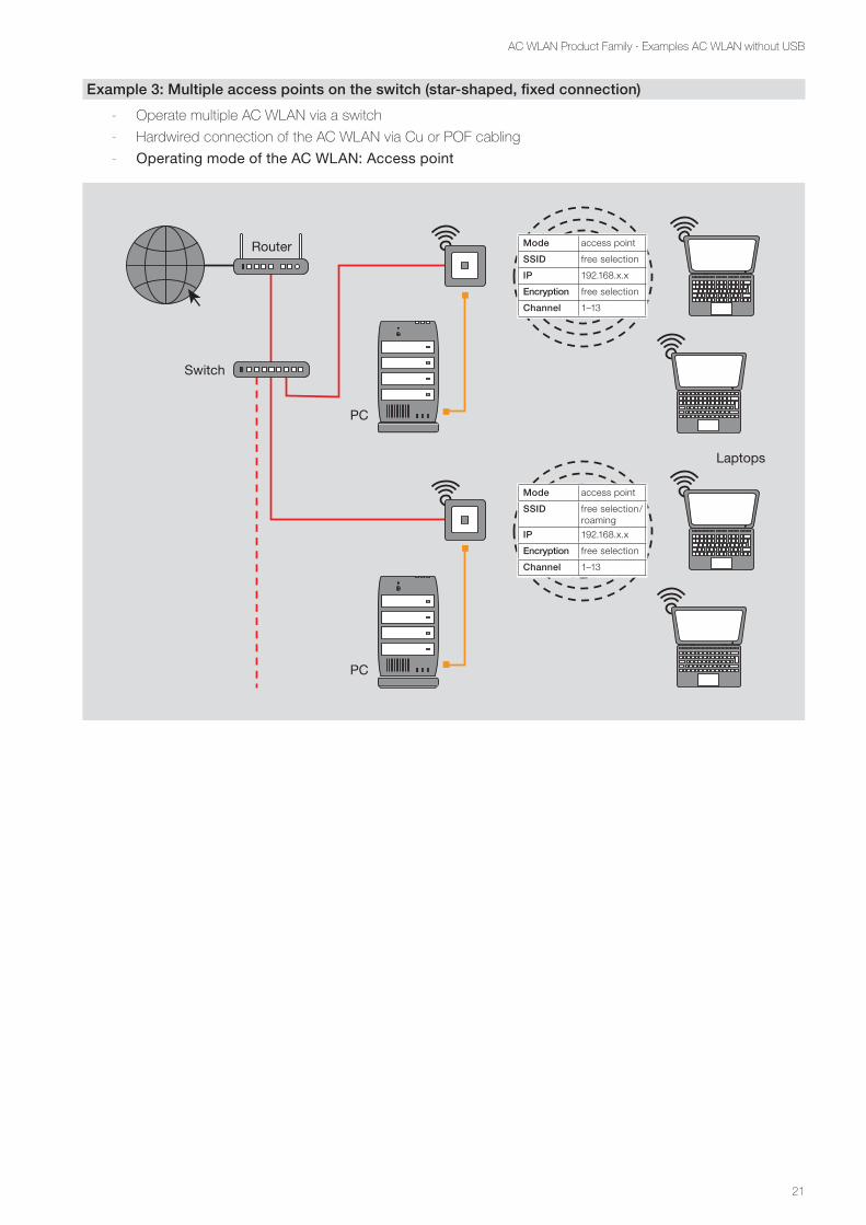
Example 3: Multiple access points on the switch (star-shaped, fixed connection)
- Operate multiple AC WLAN via a switch
- Hardwired connection of the AC WLAN via Cu or POF cabling
- Operating mode of the AC WLAN: Access point
Router
Laptops
PC
PC
Switch
Mode access point
SSID free selection
IP 192.168.x.x
Encryption free selection
Channel 1–13
Mode access point
SSID free selection/roaming
IP 192.168.x.x
Encryption free selection
Channel 1–13
22
AC WLAN Product Family · Examples AC WLAN without USB
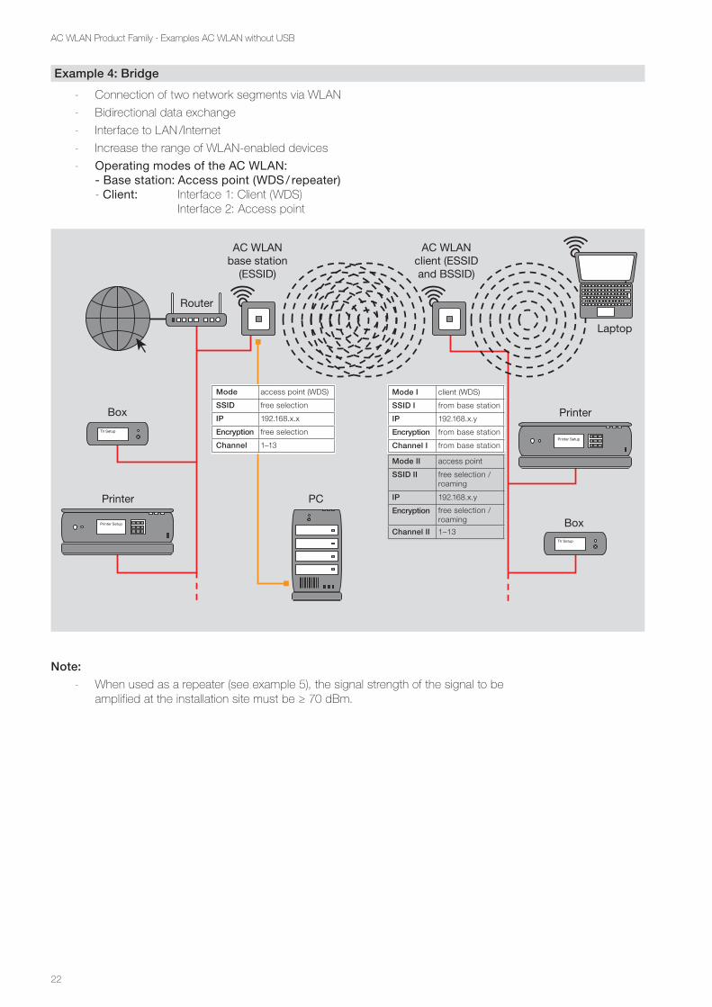
Example 4: Bridge
- Connection of two network segments via WLAN
- Bidirectional data exchange
- Interface to LAN /Internet
- Increase the range of WLAN-enabled devices
- Operating modes of the AC WLAN: - Base station: Access point (WDS / repeater) - Client: Interface 1: Client (WDS) Interface 2: Access point
Router
AC WLAN base station
(ESSID)
AC WLAN client (ESSIDand BSSID)
Laptop
Printer
PrinterBox
Box
PC
Mode access point (WDS)
SSID free selection
IP 192.168.x.x
Encryption free selection
Channel 1–13
Mode I client (WDS)
SSID I from base station
IP 192.168.x.y
Encryption from base station
Channel I from base station
Mode II access point
SSID II free selection /roaming
free selection /roaming
IP 192.168.x.y
Encryption
Channel II 1–13
Note:
- When used as a repeater (see example 5), the signal strength of the signal to be amplified at the installation site must be ≥ 70 dBm.
23
AC WLAN Product Family · Examples AC WLAN without USB
Example 5: Repeater function (RELAYED) – WLAN Range extension
• Connection of the devices to a WLAN router
• Interface to LAN / Internet
• Increase the range of WLAN enabled devices - General functionality – see first image - Exemplary application – see second illustration
• Operating modes of the AC WLAN: - Interface 1: Client (RELAYED) - Interface 2: Access point
AC WLAN 1 AC WLAN 2
Smart-phone 1
Smart-phone 2
Router
Original signal Signal strength on AC WLAN ≥ 75 dBm 2x repeated (25 % data rate),1x repeated (50 % data rate),Router 100 % data rate
possible detailing see below(not recommended any more)
Receivinginterface:client (RELAYED)
Sending interface:access point
Receivinginterface:client (RELAYED)
Sending interface:access point
Mode access point
SSID free selection
IP 192.168.x.x
Encryption free selection
Channel 1–13
Mode I client (RELAYED)
SSID I from Router
IP 192.168.x.y
Encryption from Router
Channel I from Router
Mode II access point
SSID II free selection /roaming
IP 192.168.x.y
Encryption free selection /roaming
Channel II automatically
Router
AC WLAN Client (ESSIDand BSSID)
Laptop
Box
PC
24
AC WLAN Product Family · Examples AC WLAN without USB
- When used as a repeater, the signal strength of the signal to be amplified at the installation site must be ≥ 70 dBm.
- With each ‘Repeating’, the signal cuts the data throughput and thus the overall performance of your WLAN network to half. This has physical reasons and is not a peculiarity of the AC WLAN !
Set up repeater function
General
• Install the AC WLAN correctly and in the correct position (installation height 0.3 – 1.3 m) according to the installation instructions. - After approx. one minute (after switching on) the device is ready for operation,
which is signalled by the function of the LED.
In order to be able to make the necessary settings for integration into the network, access must be made directly to the device.
• The programming of the repeater function is preferably done via the front panel or via the network in order to avoid connection interruptions after the changing of settings. It should not be done through WLAN! The AC WLAN and the accessing device must be in the same IP address range.
In repeater mode, the AC WLAN must record a WLAN signal and amplify it again. For this purpose, a second transceiver unit (interface) is activated and programmed in the AC WLAN.
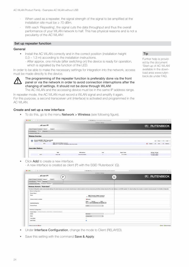
Create and set up a new interface
• To do this, go to the menu Network > Wireless (see following figure).
• Click Add to create a new interface. - A new interface is created as client (P) with the SSID ‘Rutenbeck’ (Q).
• Under Interface Configuration, change the mode to Client (RELAYED).
• Save this setting with the command Save & Apply.
Tip
Further help is provid-ed by the document ‘Start-up of AC WLAN’ available in the down-load area www.ruten-beck.de under FAQ.
QP
25
AC WLAN Product Family · Examples AC WLAN without USB
• If you have been connected to the AC WLAN via WLAN, your connection has now been disconnected.
• Reconnect to the AC WLAN through the front port or over the network until the complete setup is complete.
• Restart the AC WLAN and open the menu item Network > Wireless > Client (RELAYED). - The changes have now been applied.
• Change the SSID of the ‘Client (RELAYED)’ interface as well as the encryption password (see page 11 et seq.).
• The following settings must be identical to those of the router: - SSID - Channel number - WLAN encryption
• Customize these settings and enable the changes using the Save & Apply command button.
• Now configure the ‘other’ network ‘Access Point XY’ (R) according to your ideas.
• Activate all changes made via Save & Apply.
• To edit the respective interfaces, go back to Network > Wireless. - Here you can see a list of the individual interfaces. You can use the command
fields e.g. to change the settings and disable or remove interfaces.
R
Attention
One interface (access point) must at least be retained - otherwise you lose access to the device!
26
AC WLAN Product Family · Examples AC WLAN without USB
Example 6: Multiple repeating with roaming - free movement in the WLAN without logging in
- Increase the range of WLAN-enabled devices
- Interface to LAN / Internet
- For all WLAN devices: - same SSID - same encryption - same IP range
- Operating modes of the AC WLAN: - Base station: Access point - Per client: Interface 1: Client (RELAYED) Interface 2: Access point
Mode I client (RELAYED)
SSID from base station
IP 192.168.x.y
Encryption from base station
Channel I from base station
Mode II access point
SSID free selection /roaming
free selection /roaming
IP 192.168.x.y
Encryption
Channel II automatically
Mode I client (RELAYED)
SSID from base station
IP 192.168.x.y
Encryption from base station
Channel I from base station
Mode II access point
SSID free selection /roaming
free selection /roaming
IP 192.168.x.z
Encryption
Channel II automatically
Mode access point
SSID free selection
IP 192.168.x.x
Encryption free selection
Channel 1–13
Router
AC WLAN Base
station
AC WLAN Client 1
Laptops
Smartphone
PC
AC WLAN Client 2
Note:
• When used as a repeater (see e.g. example 5 on page 23), the signal strength of the signal to be amplified at the installation site must be ≥ 70 dBm.
27
AC WLAN Product Family · Examples AC WLAN without USB
Example 7: Repeating / forwarding via permanent connection – free movement without logging in
- Cross-border use of the Internet via WLAN, interface to the LAN / Internet, same encryption in all rooms
- Same SSID for client and base station (room 1 and 2), other SSID for room 3
- Same range for IP address for client and base station (room 1 and 2)
- Operating modes of the AC WLAN: - Base station (room 1): Access point - Client (room 2): Interface 1: Client (RELAYED) Interface 2: Access point - Access point (room 3): Access point
Mode access point
SSID free selection
IP 192.168.x.z
Encryption free selection
Channel 1–13
Mode access point
SSID free selection
IP 192.168.x.x
Encryption free selection
Channel 1–13
Mode I client (RELAYED)
SSID from base station
IP 192.168.x.y
Encryption from base station
Channel I from base station
Mode II access point
SSID free selection / roaming
free selection / roaming
IP 192.168.x.y
Encryption
Channel II automatically
RouterAC WLAN Base station
AC WLAN Client
AC WLAN Access point
Laptop
Laptop
Smartphone
PC
PC
Note:
• When used as a repeater (see e.g. example 5), the signal strength of the signal to be amplified at the installation site must be ≥ 70 dBm.
28
AC WLAN Product Family · Examples AC WLAN without USB
Example 8: Guest access
- Only Internet access via guest WLAN
- Full network access through Access point
- Hardwired connection of the AC WLAN via Cu or POF cabling
- No access to internal network
- Number of ‘guests‘ depending on the available internet bandwidth!
- Operating mode of the AC WLAN: Interface 1: Guest
Interface 2: Access point
Mode I guest
SSID automatically
IP automatically
Encryption automatically
Channel I automatically
Mode II access point
SSID free selection
IP 192.168.x.x
Encryption free selection
Channel II 1–13
Router AC WLAN
Laptops
PC
Set up guest interface
The AC WLAN offers the possibility of providing a ‘guest connection’ via WLAN. The in-house LAN as well as the access to the AC WLAN are not available to guests. To set up a guest interface, do the following:
• For the following steps, it is recommended to connect to the AC WLAN via one of the fixed network connections.
• Enter the IP address of your AC WLAN in the address bar of your browser (factory setting is 192.168.0.5).
• Then go to the Network > Wireless menu.
• Click Add to create a new interface.
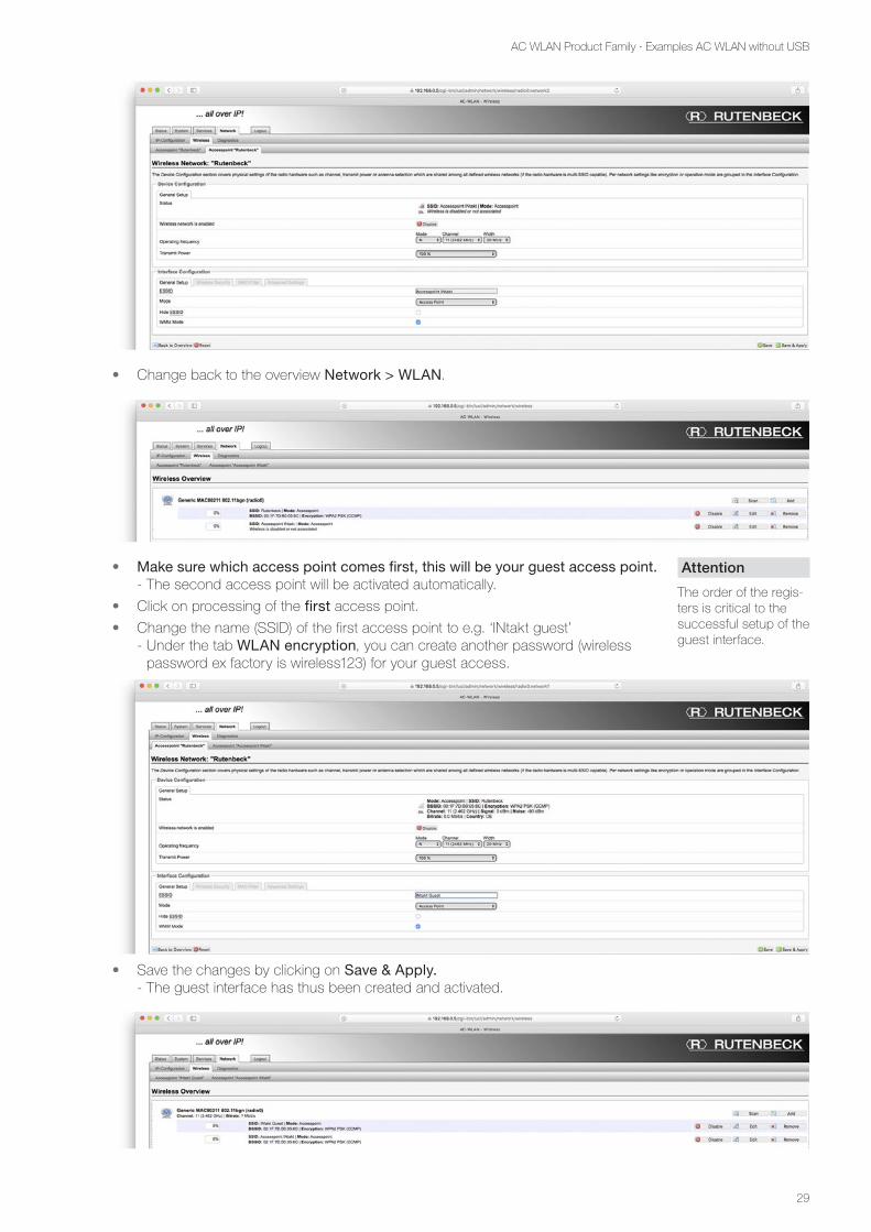
• For example, change the SSID to ‘Access point INtakt’. - This will be the main access.
• Important: Save the changes using the Save command field, not the Save & Apply command field.
29
AC WLAN Product Family · Examples AC WLAN without USB
• Change back to the overview Network > WLAN.
• Make sure which access point comes first, this will be your guest access point. - The second access point will be activated automatically.
• Click on processing of the first access point.
• Change the name (SSID) of the first access point to e.g. ‘INtakt guest’ - Under the tab WLAN encryption, you can create another password (wireless
password ex factory is wireless123) for your guest access.
• Save the changes by clicking on Save & Apply. - The guest interface has thus been created and activated.
Attention
The order of the regis-ters is critical to the successful setup of the guest interface.
30
AC WLAN Product Family · Examples AC WLAN without USB
Enable / disable guest connection
• Change to the Services > Guest Connections tab.
• Activate guest accounting offers two options. - Tick not set: The guest connection is disabled. The WLAN interface is still present
in the device and can be re-enabled later.
- Tick set: The guest connection is enabled.
• Save changes made using the Save & Apply command field.
Remove guest connection
• The Reset command can have far-reaching consequences. You receive the following message: Really shut down the network? Access to the device could be lost if you are connected through this interface.
Delete guest log
The guest log can only be viewed for reasons of data protection, but it cannot be saved.
• If necessary, delete the protocol via the red command field.
31
AC WLAN Product Family · AC WLAN with PoE
AC WLAN with PoE
Example 9: Cabling via PoE switch (e.g. Rutenbeck SR 10 GTX B PoE)
- Internet access via router and REG Switch PoE
- Star-shaped wiring to max. six AC WLAN PoE
- Bidirectional data exchange
- Connection / power supply of the PoE devices via patch cable
- Operating mode of the relevant AC WLAN PoE: Access point
Router
Laptops
toPoE
devices
to thePoE
device
to thePoE
deviceto
PoEdevices
PoE Voltagesupply
REG Switch/Switch
48 V / PoE
AC-WLAN PoE
AC-WLAN PoE
AC-WLAN PoE
AC-WLAN PoE
AC-WLAN PoE
AC-WLAN PoE
Note:
- Each AC WLAN PoE requires 15.4 W PoE power (class 0). A PoE device with PoE class 2 (7 W) can be operated on the front socket.
32
AC WLAN Product Family · AC WLAN with USB
AC WLAN with USB
Example 10: Network access to the USB interface of various devices
- Internet access via router
- Hardwired router connection of the AC WLAN via POF or Cu cabling
- Interface to LAN/Internet
- Bidirectional data exchange
- Operating mode of the AC WLAN USB: Access point
Router
Laptop
iPhone
Data on USB stick
Notes
- The USB port is a full-fledged USB 2.0 interface compatible with all USB storage devices.
- If a USB system is not sufficiently supplied with power (5 V / 500 mA), a separate power supply is required (usually included with the USB device).
Example 11: USB printer activation via LAN / WLAN
- Internet access via router
- Hardwired router connection of the AC WLAN via POF or Cu cabling
- Interface to LAN/Internet
- Bidirectional data exchange (for Apple devices via app - see page 33 et seq.)
- Printer control via print server functionality (see page 35 et seq.)
- Operating mode of the AC WLAN USB: Access point
Router
Laptop
iPhone
Printer
33
AC WLAN Product Family · AC WLAN with USB
Access for Apple devices to the USB interface of the AC WLAN via ‘File browser’ app
Since Apple offers no visible data directory (such as ‘Explorer’) on the iPhone or on the iPad, you must download a corresponding app as a replacement. The following describes the use of the ‘File Browser’ app (available for free from Apple’s App Store). Now proceed as follows:
a. b. c.
• Go to Apple’s App Store and search for ‘Rile Browser’. Install the free or paid version (Fig. a.).
• Open the file browser after the installation (Fig. b.)
• In the start window (Fig. c.) of the app, click on the + symbol in the upper right corner
d. e. f.
• In the list above, click on Computer / Network Hard Disk (Fig. d.) to connect to the USB flash drive / device.
• Click on PC (Fig. e.) in the above list to determine the type. When the connection is established, a tick appears behind the Windows icon (Fig. f.)
g. h. i.
• Touch the input field at address (Fig. g) level. Optionally, select Empty as the user name – then the query for user name and password will be omitted.
• Enter the address of the AC WLAN (USB version). By default, this 192.168.0.5 ... is 192.168.0.10 in the example (Fig. h.). And confirm with Done in the top right corner. - The AC WLAN is now displayed in the overview Remote with the Windows
symbol (Fig. i).
Tip
Before making the connection, you should already have connected the USB stick or the USB device to the AC WLAN.
Tip
If the scanning process takes too long or is disconnected, use Manual Setup.
34
AC WLAN Product Family · AC WLAN with USB
j. k. l.
• Select your AC WLAN. In the dialogue box that pops up (Fig. j or k), enter only the password - the user name in the not required in the login field (these options are not controlled by the AC WLAN but by the app). The password of the AC WLAN is factory set: wireless123
• Click on Connect. You will now see a directory share through which you can access or save the data of your USB stick / device (Fig. l).
m. n.
• If the connection cannot be established, you will receive a red marked error mes-sage (Fig. m). Click on the i.
- In the following illustration, you will find possible causes or information on trouble-shooting (Fig. n). - AC WLAN interface to cable disabled / removed - Device (iPhone or AC WLAN) switched on? - Incorrect IP address of the iPhone or the AC WLAN - No access to the IP address (incorrect IP address range / SubNet) - Firewall settings / data sharing
• When the connection is made, a drive name share is displayed.
• Click on this drive. - The files of the stick etc. are displayed.
• Click on the desired file to open it.
35
AC WLAN Product Family · AC WLAN with USB
Access to a USB printer via operating system or app
General
Via the AC WLAN in USB version you can control USB printers in two different ways:
- Direct control via a computer in the network or
- Controlling a printer with mobile devices via WLAN
Direct activation (Win)
For configuration, proceed as follows:
• Connect a USB printer via cable to the USB port of the AC WLAN.
• In the Web interface of the AC WLAN, click on the tab Services > Print Server in the Settings field to activate the button. - Leave the bidirectional mode active.
• Enable the setting using the Save & Apply command button.
• On the PC, under Control Panel > Hardware and Sound > Devices and
Printers, or under Printers and Faxes (Windows XP), add a printer by clicking the appropriate button.
• Select the option Add a local printer.
• Select Create New Port and select Default TCP/IP Port for the port type.
• Enter the host name or the IP address of the AC WLAN for Host Name or IP Address. If necessary, you can change the name of the port.
Note:
For Windows XP, the function ‘Plug & Play’ must be disabled.
36
AC WLAN Product Family · AC WLAN with USB
• Under Device Type, be sure to select Custom. Shortly thereafter, a window for selecting the selected printer will be displayed.
• If necessary, change the printer name.
• Then decide whether the printer should be ‘released’ or not. - When the printer is ‘freed’, all computers in the network of the AC WLAN have
access to the printer.
After that, you will receive a confirmation that the selected printer has been successfully added. You also have the option to print a test page.
Direct control (Mac, HP Deskjet printer as an example)
For configuration, proceed as follows:
• Plug the USB cable of the printer into the USB port of the AC WLAN.
• Activate the functionality of the print server in the AC WLAN as described under Direct Control WIN.
• From the Apple menu, go to System Settings > Printers & Scanners.
• In the local left sidebar, add a new printer using the ‘+’ sign.
• The Bonjour function automatically finds the printer under the Standard tab.
• If necessary, assign your own name for the printer.
• The printer driver is automatically loaded and can also be configured.
• The Printers & Scanners dialogue box allows you to share the printer on the Network.
Direct control (Linux, HP Deskjet printer as an example)
For configuration, proceed as follows:
• Plug the USB cable of the printer into the USB port of the AC WLAN.
• Enable the functionality of the print server in the AC WLAN as described under Direct Control WIN.
• Go to the settings on the PC and select the Printer icon in the Hardware section.
• Confirm the button Add.
• Click on the option Find network printer and, under Host, enter the IP address of the AC WLAN to which the USB printer is connected.
37
AC WLAN Product Family · AC WLAN with USB
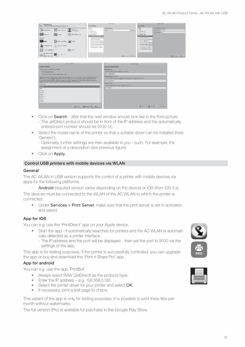
• Click on Search - after that the next window should look like in the third picture.
- The JetDirect protocol should be in front of the IP address and the automatically entered port number should be 9100 (V).
• Select the model name of the printer so that a suitable driver can be installed (here ‘Generic’). - Optionally, further settings are then available to you - such. For example, the
assignment of a description (see previous figure).
• Click on Apply.
Control USB printers with mobile devices via WLAN
General
The AC WLAN in USB version supports the control of a printer with mobile devices via apps for the following platforms:
- Android (required version varies depending on the device) or iOS (from iOS 5.x)
The devices must be connected to the WLAN of the AC WLAN to which the printer is connected.
• Under Services > Print Server, make sure that the print server is set to activated and saved.
App for iOS
You can e.g. use the ‘PrintDirect’ app on your Apple device.
• Start the app - it automatically searches for printers and the AC WLAN is automati-cally detected as a printer interface. - The IP address and the port will be displayed - then set the port to 9100 via the
settings of the app.
This app is for testing purposes. If the printer is successfully controlled, you can upgrade the app or buy and download the ‘Print n Share Pro’ app.
App for android
You can e.g. use the app ‘PrintBot’.
• Always select RAW (JetDirect) as the protocol type.• Enter the IP address – e.g. 192.168.0.126.• Select the printer driver for your printer and select OK.• If necessary, print a test page to check.
This variant of the app is only for testing purposes. It is possible to print three files per month without watermarks.
The full version (Pro) is available for purchase in the Google Play Store.
38
AC WLAN Product Family · AC WLAN with USB
Example 12: Router-independent internet access via LTE stick
- Internet access via LTE stick on AC WLAN USB
- Bidirectional data exchange
- Operating mode of the AC WLAN USB: Access point
Laptop
Smart-phone
Router
LTE stick
Set up router-independent Internet access via LTE stick
General
The AC WLAN USB supports a variety of GSM / LTE sticks. A constantly updating list of compatible sticks can be found in the download area at www.rutenbeck.de
• Please note that due to the large number of firmware variants of the different manufacturers, small deviations in the procedure may occur.
For configuration, proceed as follows:
• Plug the GSM / LTE stick into the USB port of the AC WLAN.
• Enter the IP address of the AC WLAN USB into your browser.
• Log in by means of a password.
• Call up the settings for DHCP server via Network > IP Configuration > LAN.
• Uncheck ‘Ignore interfaces’ to enable the DHCP server. - If necessary, you can change the settings of the DHCP server that have been
made visible regarding ‘Start’, ‘Limit’, and ‘Uptime’.
• Apply the settings with Save & Apply.
• Under Network > IP Configuration, add a new interface.
39
AC WLAN Product Family · AC WLAN with USB
• Assign exactly the name ‘mobile’ to the interface.
• Select as protocol ‘UMTS / GPRS / EV-DO’.
• Confirm the settings using the command field Submit.
The interface must now be configured.
• To this end, enter the access data of the provider.
• If you enter the PIN number of the SIM card incorrectly, your SIM card will be blocked!
• As modem device, ‘/dev/tty/USB0’ must be used. - The entry is available after about 30 seconds after the stick has been inserted.
After about half a minute, the GSM / LTE stick should have connected to the mobile network.
• After clicking the Save & Apply command button, the display changes to Network > IP Configuration.
Now you can establish a connection to the devices via the LAN or WLAN interface of the AC WLAN and they are automatically assigned an IP address.
The configuration is now complete.
Note:
Smartphones in the vicinity are also dis-played in the overview with the designation MOBILE.
When editing, make sure you select the LTE stick.
40
AC WLAN Product Family · AC WLAN with USB
Example 13: Connection of a Smart TV without an own WLAN interface
- Internet access via router
- Interface to LAN / Internet
- Bidirectional data exchange
- Connection e.g. of a Smart TV via patch cable
- Operating mode of the AC WLAN USB: Access point
Router
DataUSB stick
Smart-Phone
Smart TV
The router connected to the Internet has an AC WLAN connected to it via a cable connec-tion. Via a Smartphone, the control of a USB data storage – e.g. a 16 GB stick – is possible.
Notes:
- Depending on the Smartphone manufacturer, an additional software (app) may be required (possibly subject to a charge). The procedure is described on page 33 et seq.
- The additional network socket on the AC WLAN allows direct connection of the Smart TV to the network / internet.
41
AC WLAN Product Family · AC WLAN with USB
Example 14: Mobile hotspot on the smartphone
- Internet access via smartphone with active hotspot
- Bidirectional data exchange
- Data exchange and / or printer activation
- Connection e.g. of a Smart TV via patch cable
- Operating mode of the AC WLAN USB: Client (RELAYED)
Mode hotspot
SSID free selection
IP fix via smartphone
Encryption free selection
Channel fix via smartphone
Mode I Client (RELAYED)
SSID I from hotspot
IP f. hotspot (DHCP)
Encryption from hotspot
Channel I from base station
Mode II virtualaccess point
SSID II free selectionroaming
IP from hotspot(DHCP)
Encryption free selectionroaming
Channel II automatically
Smartphone with active
hotspot
AC WLAN Client (ESSIDand BSSID) Laptop
Box
PC
Notes:
- IMPORTANT: All devices must be set to DHCP.
- Depending on the hotspot, only a limited number of simultaneous devices at the hotspot is possible!
- The data throughput and the number of possible devices depend in this mode exclusively on the technical characteristics of the hotspot. Please observe the operator / manufacturer information!
42
AC WLAN Product Family · Advanced functions
Advanced functions
Remote control (possible from Firmware 4.x)
From version 4.x, it is possible to centrally configure other networked AC WLANs.
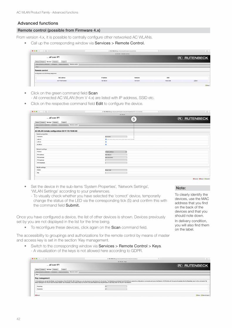
• Call up the corresponding window via Services > Remote Control.
• Click on the green command field Scan - All connected AC WLAN (from V 4.x) are listed with IP address, SSID etc.
• Click on the respective command field Edit to configure the device.
• Set the device in the sub-items ‘System Properties’, ‘Network Settings’, ‘WLAN Settings’ according to your preferences. - To visually check whether you have selected the ‘correct’ device, temporarily
change the status of the LED via the corresponding tick (S) and confirm this with the command field Submit.
Once you have configured a device, the list of other devices is shown. Devices previously set by you are not displayed in the list for the time being.
• To reconfigure these devices, click again on the Scan command field.
The accessibility to groupings and authorizations for the remote control by means of master and access key is set in the section ‘Key management.
• Switch to the corresponding window via Services > Remote Control > Keys. - A visualization of the keys is not allowed here according to GDPR.
Note:
To clearly identify the devices, use the MAC address that you find on the back of the devices and that you should note down.
In delivery condition, you will also find them on the label.
S
43
AC WLAN Product Family · Advanced functions
The master key ‘symbolizes’ the AC WLAN from which the configuration commands are sent and which scans the network. AC WLANs with identical access keys respond to these commands.
• In delivery condition, both passwords are not assigned. Thus, all AC WLANs have the same master and access key - i.e. each AC WLAN is allowed to configure any other AC WLAN on the same network.
To change this mechanism, proceed as follows:
• Enter separate passwords under Services > Remote control > Keys and save them using the corresponding command field. - For the WLAN passwords via the remote control system, only the following
characters may be used for system-related reasons: All printable ASCII characters from 32 (spaces) to 126 except quotation marks (34) and high bar (39).
- The password length must be between 8 and 63 characters.
Timer function for LAN / WLAN
The AC WLAN has an integrated timer functionality with extensive definition options.
• If you switch off the WLAN, where you are currently logged in, via software, you can only access the device again as follows:
- Access via the wired network
- Access via the front socket
- Access via reset
- If you have switched off WLAN and LAN manually, a new access to the device is only possible via the wired network or after a reset!
General information about enabling and disabling the WLAN
The WLAN can be enabled or disabled by the timer function as well as in the WLAN set-tings. If several WLAN interfaces have been created, they can be enabled / disabled individ-ually in the WLAN settings. In the timer function, all WLAN interfaces are always enabled / disabled at the same time (the tick ‘Activate timer’ must be set).
If a WLAN interface has been enabled / disabled in the WLAN settings via the corresponding button, then this setting is retained until the next switching time created in the timer. If the timer is disabled, the connection is disconnected until it is re-enabled. Devices that are likewise connected will be disconnected at the set time.
Set up timer function
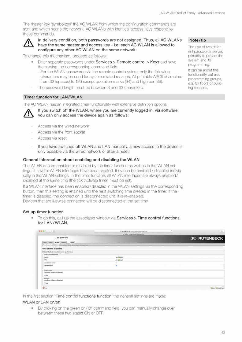
• To do this, call up the associated window via Services > Time control functions for LAN / WLAN.
In the first section ‘Time control functions function’ the general settings are made:
WLAN or LAN on/off
• By clicking on the green on / off command field, you can manually change over between these two states ON or OFF.
Note / tip
The use of two differ-ent passwords serves primarily to protect the system and its programming.
It can be about this functionality but also programming groups, e.g. for floors or build-ing sections.
44
AC WLAN Product Family · Advanced functions
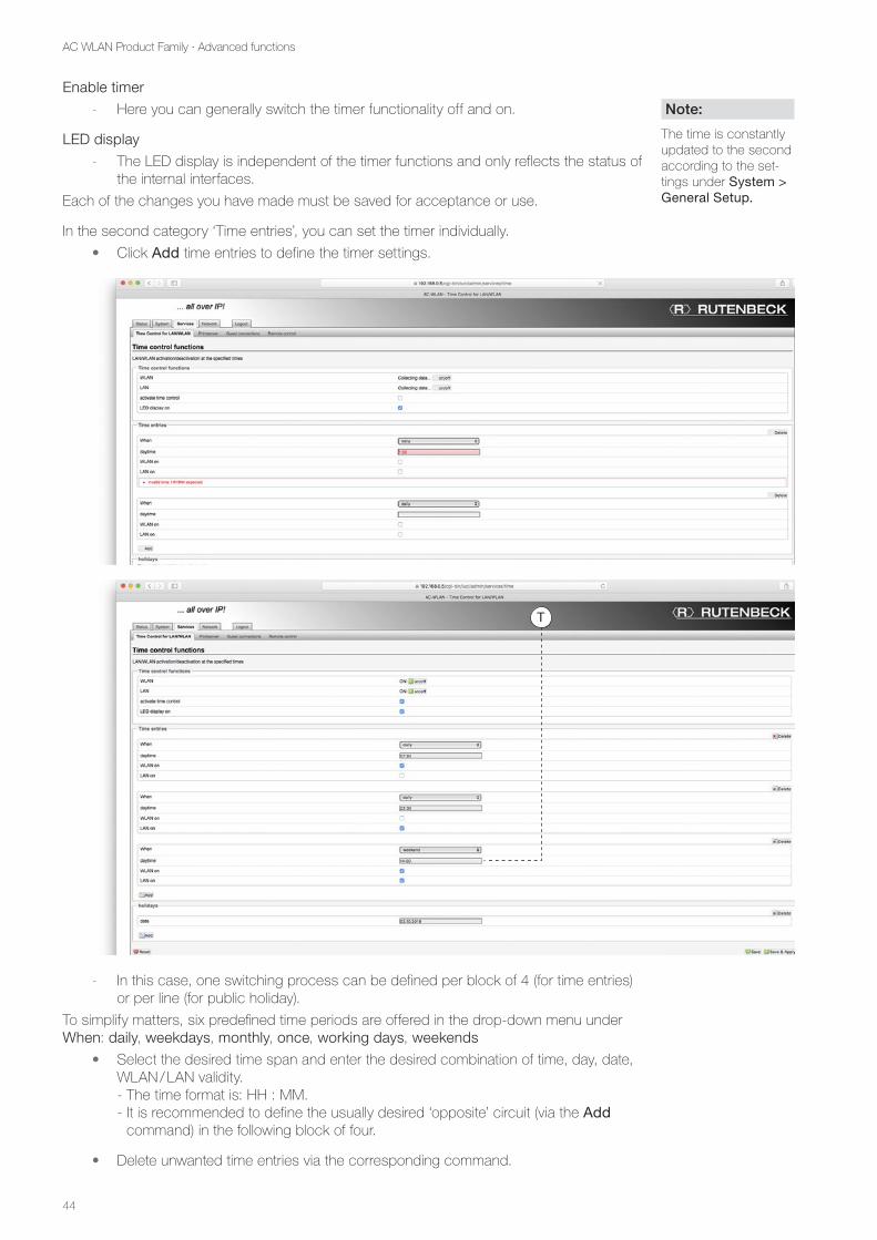
Enable timer
- Here you can generally switch the timer functionality off and on.
LED display
- The LED display is independent of the timer functions and only reflects the status of the internal interfaces.
Each of the changes you have made must be saved for acceptance or use.
In the second category ‘Time entries’, you can set the timer individually.
• Click Add time entries to define the timer settings.
- In this case, one switching process can be defined per block of 4 (for time entries) or per line (for public holiday).
To simplify matters, six predefined time periods are offered in the drop-down menu under When: daily, weekdays, monthly, once, working days, weekends
• Select the desired time span and enter the desired combination of time, day, date, WLAN / LAN validity. - The time format is: HH : MM. - It is recommended to define the usually desired ‘opposite’ circuit (via the Add
command) in the following block of four.
• Delete unwanted time entries via the corresponding command.
Note:
The time is constantly updated to the second according to the set-tings under System > General Setup.
T
45
AC WLAN Product Family · Advanced functions
In addition, holidays can be defined.
• Enter the respective date in the order DD.MM.YYYY. - The holiday circuit is treated as defined under Weekend. - If there are no time entries for weekend - see previous figure (T), nothing
happens on the set holidays!
• Activate the switching times via the Save & Apply button.
Control AC WLAN via UDP
The WLAN interface of the device can be switched on and off via UDP command.
• Switch to the System > System tab. - In the delivery state, no port is set.
• Enter the desired port (U) in the System Properties field and save the entry using Save & Apply.
• To take over the entered UDP port, it is absolutely necessary to restart the AC WLAN..
• To do this, click on the System > Reboot tab and Perform reboot in the window that opens. - The restart takes approx. one minute. - After that, the UDP function is available.
Via WLAN (smartphone / tablet), switching-off is possible, but no switching-on.
UDP commands
Command Meaning
WLAN ON Turning on WLAN interface
WLAN OFF Turning off WLAN interface
WLAN ? Check status
- When making entries, pay attention to capitalization and spaces.
- The AC WLAN confirms a sent UDP command by returning the current state.
U
46
AC WLAN Product Family · Advanced functions
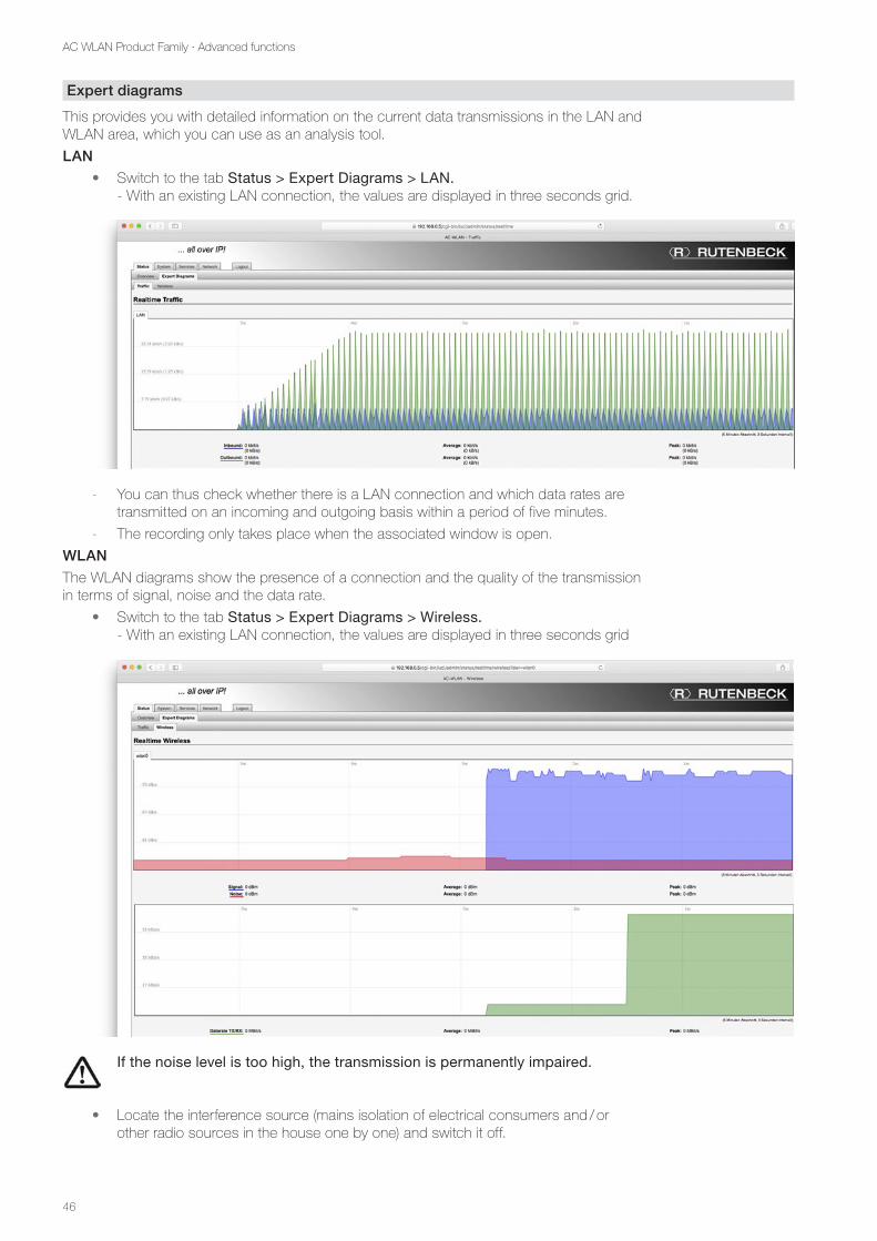
Expert diagrams
This provides you with detailed information on the current data transmissions in the LAN and WLAN area, which you can use as an analysis tool.
LAN
• Switch to the tab Status > Expert Diagrams > LAN. - With an existing LAN connection, the values are displayed in three seconds grid.
- You can thus check whether there is a LAN connection and which data rates are transmitted on an incoming and outgoing basis within a period of five minutes.
- The recording only takes place when the associated window is open.
WLAN
The WLAN diagrams show the presence of a connection and the quality of the transmission in terms of signal, noise and the data rate.
• Switch to the tab Status > Expert Diagrams > Wireless. - With an existing LAN connection, the values are displayed in three seconds grid
• If the noise level is too high, the transmission is permanently impaired.
• Locate the interference source (mains isolation of electrical consumers and / or other radio sources in the house one by one) and switch it off.
47
AC WLAN Product Family · Advanced functions
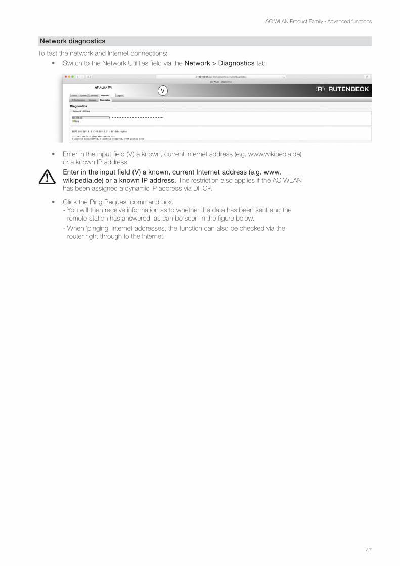
Network diagnostics
To test the network and Internet connections:
• Switch to the Network Utilities field via the Network > Diagnostics tab.
• Enter in the input field (V) a known, current Internet address (e.g. www.wikipedia.de) or a known IP address.
• Enter in the input field (V) a known, current Internet address (e.g. www. wikipedia.de) or a known IP address. The restriction also applies if the AC WLAN has been assigned a dynamic IP address via DHCP.
• Click the Ping Request command box. - You will then receive information as to whether the data has been sent and the
remote station has answered, as can be seen in the figure below.
- When ‘pinging’ internet addresses, the function can also be checked via the router right through to the Internet.
V
48
AC WLAN Product Family · Command Reference
Command Reference
So far, most of the settings have been described in a functional context or as examples.
Not all setting options were discussed in detail, as this would usually have led to an unma-nageable amount of information. For completeness, individual setting options / functionali-ties in the order of the tabs and sub-tabs are described below.
Status
All settings and functions have already been described – e.g. see Expert Diagrams on page 46.
System > System
Time synchronisation
The Network Time Protocol (NTP) is a standard for synchronizing clocks in computer sys-tems over packet-based communication networks. NTP uses the connectionless transport protocol UDP. It has been specifically designed to provide reliable time information over vari-able packet delay networks.
The setting is mainly relevant for the timer function (see page 43 et seq.) of the AC WLAN.
Enable NTP client• Enable this option so that the AC WLAN can access preset time servers (NTP) of
the respective time zone via the internet in order to ensure a reliable time control.
Offer NTP server• Enable the NTP server to use the AC WLAN as an NTP server for devices within
the network.
NTP server candidates• Here you have the option of defining, adding or deleting various NTP servers. The
most common NTP servers are pre-set for Europe. - An NTP server always stays selected.
49
AC WLAN Product Family · Command Reference
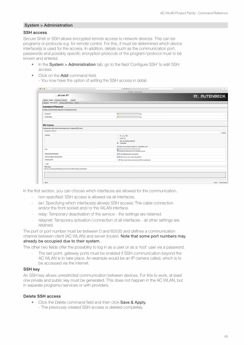
System > Administration
SSH access
Secure Shell or SSH allows encrypted remote access to network devices. This can be programs or protocols e.g. for remote control. For this, it must be determined which device interface(s) is used for the access. In addition, details such as the communication port, passwords and possibly specific encryption protocols of the program / protocol must to be known and entered.
• In the System > Administration tab, go to the field ‘Configure SSH’ to edit SSH access.
• Click on the Add command field. - You now have the option of setting the SSH access in detail.
In the first section, you can choose which interfaces are allowed for the communication.
- non-specified: SSH access is allowed via all interfaces.
- lan: Specifying which interface(s) allow(s) SSH access: The cable connection and/or the front socket and / or the WLAN interface.
- relay: Temporary deactivation of the service - the settings are retained.
- relaynet: Temporary activation / connection of all interfaces - all other settings are retained.
The port or port number must be between 0 and 65535 and defines a communication channel between client (AC-WLAN) and server (router). Note that some port numbers may already be occupied due to their system.
The other two fields offer the possibility to log in as a user or as a ‘root’ user via a password.
- The last point, gateway ports must be enabled if SSH communication beyond the AC WLAN is to take place. An example would be an IP camera called, which is to be accessed via the internet.
SSH key
An SSH key allows unrestricted communication between devices. For this to work, at least one private and public key must be generated. This does not happen in the AC WLAN, but in separate programs / services or with providers.
Delete SSH access
• Click the Delete command field and then click Save & Apply. - The previously created SSH access is deleted completely.
50
AC WLAN Product Family · Command Reference
Network
Set up VLAN (port-based)
VLANs allow you to set up logical subnetworks within a network structure. The data of a subnetwork are not automatically forwarded to another VLAN. The switches in the network must support this function (VLAN according to IEEE 802.3q).
• Click on the Network tab.
• Click the Create interface command button.
• Enter the name of the new interface – e. g. VLAN01. - This name / ID must be identical for all devices within the same VLAN!
• Select a protocol (see figure on the right) for the new interface. - With static address assignment (recommended), a detailing is required after
the interface has been created (see following figure).
• Create a network bridge by ticking there (X). Only if the network bridge is set up, several interfaces can be selected / covered in the following field.
• Set the designation (W) of the custom interface.
• Click the Submit command button to save the settings. - Then the newly generated interface (here VLAN01) becomes visible in the register
Network and can be specified further.
XW
51
AC WLAN Product Family · Command Reference
• Common configuration - General setup
Protocol
You have the following possibilities:
Static address
- The IP address is assigned permanently. Recommended for the most secure configuration.
DHCP Client
- The IP address assignment takes place automatically via the router / server.
The following settings with additional information are required in case the device is operated via LTE / GSM-Stick. This sets the procedure for authentication to the provider.
• Please note the information provided by your provider or the LTE / GSM stick!
The following settings are available:
- PPP - PPtP - PPPoE - PPPoATM
- UMTS / GPRS / EV-DO - L2TP - PPPoSSH
IPv4 address
- An Internet Protocol (IP) address is a numeric designation. Each device connected to a network has an assigned IP address. This IP address uses the internet protocol for the communication.
IPv4 netmask
You have various possibilities:
- 55.255.255.0 Standard setting
- 55.255.0.0 Useful for ‘big’ networks with more than 254 devices.
IPv4 broadcast
Each subnet / netmask has a reserved broadcast address that allows all network subscrib-ers to be reached independently of the device IP. Usually this is the last address (255 = limited broadcast) of the respective subnet / netmask (eg 255.255.255.255).
If another broadcast address is to be used, specify it.
Use own DNS servers
If your network has its own DNS server, it can be specified here.
52
AC WLAN Product Family · Command Reference
• Common configuration – Advanced Settings
Overwrite MAC address
- Some programs or network configurations require a specific MAC address in the adapter. At this point, an adaptation can be made directly in the AC WLAN.
Overwrite MTU value
- The Maximum Transmission Unit (MTU) describes the maximum size of the user data that can be transmitted in a single data packet. For DSL connections made via PPPoE (Point to Point Protocol over Ethernet), the max. MTU is e.g. 1.492 bytes. The internet provider can reduce the MTU by using additional protocols.
Use gateway metrics
- For manual gateway metric setting e.g. the PC network adapter, this can also be adapted here.
IPTV mode (IGMP snooping)
- Version 3 of the IGMP snooping protocol is used or automatically switched to the lower version of a remote site (router, switch, etc.). This issue can help with prob-lems with IP / video streaming.
• DHP server – General Setup
If the DHCP server is enabled, the AC WLAN assumes the IP address assignment within the network according to the configuration – e.g. in training networks without their own router, which are only used occasionally.
• Click on the command field Configure DHCP server to make the necessary settings.
• DHCP server - General setup
Ignore interface
- DHCP server will be turned off.
Start
- The first IP address in the automatically assigned area. If the device has the IP address 192.168.0.x, the first automatic address is 192.168.0.100.
Limit
- Maximum number of IP addresses that can be assigned via the DHCP server.
Running time
- The time for which the assigned IP address is stored.
53
AC WLAN Product Family · Command Reference
• DHCP server – Advanced Settings
• Expert knowledge - these settings require extensive knowledge of network technology and system administration. Only change these settings if you have the appropriate knowledge.
Network > Wireless > interface
Interface configuration
The MAC address is a unique device identifier and assigned only once per device!
• Switch to one of the defined interfaces via the tab Network > Wireless and into the corresponding field Interface configuration.
Mac filter
- Here, you it can be filtered which devices can access the device / network. As a result, external devices may e.g. be excluded. The following variants are possible - disable - only allow listed ones - allow all except for listed ones
Advanced settings
- The default interface name is replaced by the name entered here.
54
AC WLAN Product Family · Annex
Annex
Range of transmit power
The range of the transmit power e.g. depends on the structural infrastructure. Adjust the location for the AC WLAN to the spatial conditions and comply with the recommended installation height of 30 to 130 cm.
The graph shows the reception performance as a function of the transmit power and the distance to the AC WLAN for concrete walls as an example.
Back (at wall) Back (at wall)
Front (in the room)
Metres Metres
Front (in the room)
49 % transmit power 100 % transmit power
Legend
> –70 dBm reception possible
–60 bis –70 dBm good to medium reception
0 to –60 dBm very good to good reception
55
AC WLAN Product Family · Annex
Factory settings
Irrespective of the version, the AC WLAN is delivered with the following basic settings from the factory.
Please note your own settings!
Delivery condition Own settings Own settings
System / Administration
Password admin
System / System
Host name AC-WLAN
Language German
UDP Port Not specified
Netzwork / LAN / settings
Protocoll Static address
IPv4 address 192.168.0.5
IPv4 netmask 255.255.255.0
IPv4 gateway Not specified
DNS server Not specified
Netzwork / WLAN / settings
Activated interfaces All
Channel 11
Transmit power 100 %
(E)SSID Rutenbeck
Mode Access point
WMM mode Enabled
Netzwork / WLAN / extended settings
Mode IEEE802.11 n
Channel bandwidth 20 MHz
Network / WLAN / WLAN encryption
Encryption WPA2-PSK
Encryption algorithm auto
Key wireless123
Services
Guest / time control Not enabled
LED
LAN (RJ45) Enabled
WLAN Enabled
56
AC WLAN Product Family · Annex
Adjustments when accessing the AC WLAN through Apple mobile devices
AC WLAN and the accessing device (iPhone / iPad) must be in the same IP address range. The following describes the procedure for accessing via WLAN via an iPhone / iPad:
• If you have not already done so, turn on the WLAN switch in the Settings Apple menu. - The device will connect to a locally available WLAN network, as far as this is / was
already known in the network!
• Otherwise, select from the available WLAN networks that of the AC WLAN to be configured and select this by tapping. - In this example ‘Rutenbeck‘ - The password is requested. In delivery condition, this is ‘wireless123‘.
• After entering, select the command Connect. - For a successful connection, the IP address of the iPhone / iPad must be adapted
to the address range of the AC WLAN.
• On the device (Rutenbeck) that is selected now, tap on the info symbol (below the WLAN switch).
• - Typically, you will see values for DHCP that prevent you from connecting to AC WLAN.
57
AC WLAN Product Family · Annex
• Change from the category DHCP to the category Static - The values for IP address and subnet mask must be entered manually in the emp-
ty fields.
• IP address: The first 3 blocks must be 192.168.0.x. The last position must not be 0, 5 or less than 256 and must not be assigned twice in the network!
• Subnet Mask: 255.255.255.0
• Exit the dialogue box by clicking on the WLAN button at the top centre to return to the list of WLAN (wireless) networks. - If the settings are correct, the connection to the AC WLAN is now established!
This is indicated by a check mark in front of the entry Rutenbeck.
• Open the Safari browser of your iPhone / iPad and enter the address of the AC WLAN in the address bar! In delivery condition, this is: 192.168.0.5 - You will receive a security prompt, which is, however, due to technical conditions,
because the AC WLAN is ‘just’ a device (see also page 10).
• Click Continue to access the web interface of the AC WLAN. - You are now on the user interface of the AC WLAN, which you can configure
according to your wishes after entering the password (in the delivery status, this is admin).
58
AC WLAN Product Family · Annex
Help with malfunctions
LEDs do not light up
Cause Action
The AC WLAN is without supply voltage. Switch on the supply voltage.
LAN LED (orange) does not light up
Cause Action
The LAN interface has been disabled or the LED indicator has been disabled on the ‘Timer’ page.
Switch the deactivated function on again.
WLAN LED (blue) does not light up
Cause Action
The LAN interface has been disabled or the LED indi-cator has been disabled on the ‘Timer function’ page.
Switch the deactivated function on again.
No connection to WLAN possible
Cause Action
The device is out of range of the AC WLAN. Reduce the distance between the devices.
On the AC WLAN used as a repeater, the reception power on the part of the base station is too low.
Change the mounting location of the AC WLAN used as a repeater and make sure that the received power there is at least 70 dBm.
The WLAN feature of your AC WLAN is disabled. Activate the WLAN function.
Another wireless network causes interference. Set another channel or set the channel to ‘auto’.
The encryption of your AC WLAN is set incorrectly. In the user interface, set the encryption to WPA WPA2.
The SSID is set to ‘not visible’ when you log in to the WLAN for the first time.
For the first connection the SSID must be ‘visible’. Set the SSID to ‘visible’. After establishing the connection, the SSID can be set to ‘not visible’ again.
No connection to the internet
Cause Action
IP address range and subnet of the device are not correct – or the device may be set to DHCP. The gateway address (router) was not entered.
Make appropriate adjustments to the settings on the device or AC WLAN.
A firewall runs on the devices. Allow the firewall to access the network.
The AC WLAN cannot be found under the factory IP address
Cause Action
You have activated the DHCP client on AC WLAN. If necessary, perform a reset or use utilities such as ‘Fing’ to identify the IP address.
59
AC WLAN Product Family · Annex
Glossary
Designation Abbrev. Function
Access point AP Base station, interface for wireless communication, devices are registered via WLAN at the access point, which is wired to the network, comparable to bridges or switches, based on Layer 2.
Adapter Connects a wired communication device via WLAN to an access point.
Advanced Encryption Standard
AES Freely available encryption algorithm with 128, 192 or 256 bit key length and 128 bit block size.
Basic Service Set BSS Created by synchronization of relevant parameters by multiple devices.
Basic Service Set Identifier
BSSID Matches either the MAC address of the AP or is randomly generated and unequivocally identifies each BSS.
Cipher Mode in which texts can be encrypted that are longer than the block cipher length (e.g. AES).
Client Connects a wired communication device via WLAN to an AP, also referred to as a repeater and wireless adapter
DNS Server Computer (server) that does the name resolution
Domain Name System DNS Is the name resolution, i.e. conversion of a host name into the associated IP address.
Extended Service Set ESS Coupling of several WLAN radio cells to a larger radio cell.
Extended Service Set Identifier
ESSID Connecting multiple APs to a network requires the same SSID, which in this case is called ESSID.
High Throughput HT mode In the HT-40 mode, a greater bandwidth and thus greater speed are possible. Range is reduced, speed advantage only partially realistic (IEEE 802.11n devices required, optimal connection required).
Independent Basic Ser-vice Set
IBSS IBSS is a closed network, without connection to other networks.
IPv4 address Fourth version of the Internet Protocol, 32-bit address in four blocks of 8-bit decimal notation, a range of 0-255 and separated by periods (xxx.xxx.xxx.xxx).
IPv4 gateway Connects networks of different protocols with each other, indicates the path to the internet.
IPv4 netmask Distribution between network and address part of the IP address, com-puters are in the same network if the address part is the same (the bits of the netmask which are equal to ‘1’).
Channel The available frequency range in the 2.4 GHz range is divided into 14 channels for better utilization, with the first 13 available in Europe.
Copper cable Cu Network cable
Local Area Network LAN Local network with max. 500 meters expansion, mostly home to small businesses.
Polymer Optical Fibre POF Plastic optical fibre
Port Part of a network address to map packets between client and server. With UDP, the port number of the service is sent, which should receive the data.
Power over Ethernet PoE Power over the network line (given a network infrastructure).
60
AC WLAN Product Family · Annex
Designation Abbrev. Function
Print server Accepts print jobs in a computer network and forwards them to printers.
Protocol Software agreement for data transmission
Repeater Signal amplifier, which increases the range
Key Host name
Password
Roaming
Name of the access point
Access protection
Take the WLAN connection from one AP to the next AP.
Secure Shell SSH / Open SSH
Technology that encrypts all traffic to prevent eavesdropping, hijacking and other attacks. In addition, OpenSSH offers a wide range of secure tunnelling capabilities, various authentication methods, and advanced configuration options.
Transmit power Delivered power of the AP - usually given in dBm.
Service Set Identifier SSID Freely selectable name of a WLAN, up to 32 characters long, setting in the AP and all connected clients.
Temporal Key Integrity Protocol
TKIP Security protocol in WLAN or other wireless networks based on the IEEE 802.11 standard.
Universal Serial Bus USB Serial interface for transferring data - Use in AC WLAN: USB 2.0
User Datagram Protocol UDP Simple, connectionless network protocol for the transmission of data. To assign the data to the right applications, ports are used.
VLAN A Virtual Local Area Network is a logical subnet within a physical network. It can spread across multiple switches.
WDS Method for addressing data frames, setting up a wireless network with several APs, WDS both with a WLAN interface (single-radio WDS, con-nection to the AP and client), as well as with multiple dual-radio WDS, an interface to the AP and a different to the client) at the AP, distinction in bridging (2 WLAN bridges connected) and repeating mode (multiple APs connected via WDS).