33
AC05 AC05 Intronics Power Inc. 1400 Providence Highway, Building 2, Norwood, MA 02062-5015 ● Phone: 1-781-551-5500 ● Fax: 1-781-551-5555

AC05AC05
Intronics Power Inc. 1400 Providence Highway, Building 2, Norwood, MA 02062-5015 ●
Phone: 1-781-551-5500 ●
Fax: 1-781-551-5555
FILE NAME: AC350 Series.doc, REVISION: July 12, 2007 V10
1
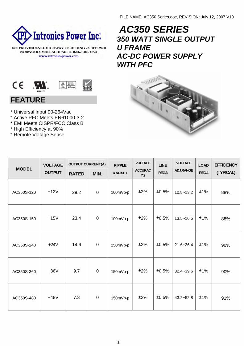
AC350 SERIES 350 WATT SINGLE OUTPUT U FRAME
AC-DC POWER SUPPLY WITH PFC
FEATURE * Universal lnput 90-264Vac * Active PFC Meets EN61000-3-2 * EMI Meets CISPR/FCC Class B * High Efficiency at 90% * Remote Voltage Sense
OUTPUT CURRENT(A) MODEL
VOLTAGE
OUTPUT RATED MIN.
RIPPLE
& NOISE 1
VOLTAGE
ACCURACY 2
LINE
REG.3
VOLTAGE
ADJ.RANGE LOAD
REG.4
EFFICIENCY (TYPICAL)
AC350S-120 +12V 29.2 0 100mVp-p ±2% ±0.5% 10.8~13.2 ±1% 88%
AC350S-150 +15V 23.4 0 100mVp-p ±2% ±0.5% 13.5~16.5 ±1% 88%
AC350S-240 +24V 14.6 0 150mVp-p ±2% ±0.5% 21.6~26.4 ±1% 90%
AC350S-360 +36V 9.7 0 150mVp-p ±2% ±0.5% 32.4~39.6 ±1% 90%
AC350S-480 +48V 7.3 0 150mVp-p ±2% ±0.5% 43.2~52.8 ±1% 91%

FILE NAME: AC350 Series.doc, REVISION: July 12, 2007 V10
2
SPECIFICATIONS Typical at 25℃, nominal line and 75% load, unless otherwise Specified
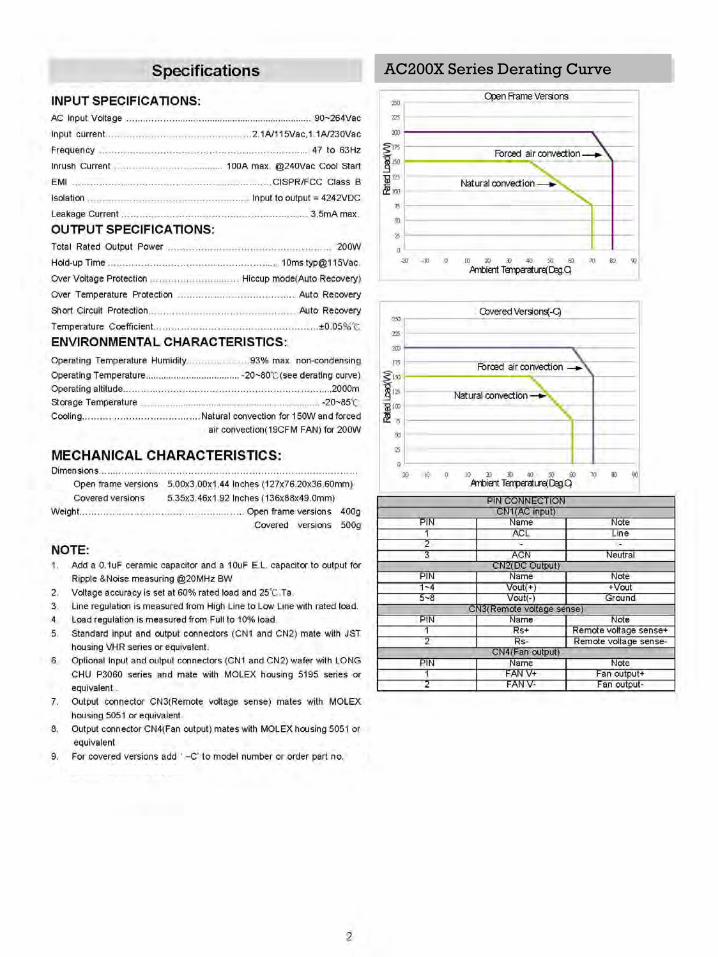
INPUT SPECIFICATIONS: AC350S Series Derating Curve AC lnput Voltage …....………........…........................................... 90~264Vac Frequency ………………………………………….……………..... 47 to 63Hz lnrush Current ………………….……………....................................... 85A max.
EMI …………………………..…………………………..……CISPR/FCC Class B
lsolation ……………………………………………...…lnput to output =3000VDC
Leakage Current………………………………………………….……… 2mA max
OUTPUT SPECIFICATIONS:
Total Rated Output Power……………………………………………………350W (with 20CFM air flow or optional fan)
Remote Voltage Sense………………………..…Compensates for wire Voltage Hold-up Time ………………………………………………………..……16mS typ. Over Voltage Protection………………………..…….Recycle AC input to restart Over Temperature Protection……………….………………….….Auto Recovery Short Circuit Protection…………………………………..………. .Auto Recovery
ENVIRONMENTAL CHARACTERISTICS:
0102030405060708090
100
-10 0 10 20 30 40 50 60 70Ambient Temperature(Deg.C)
Load
(%)
Operating Temperature ......................................................................-10~65℃
45~65℃ with 2%/℃ Derating
PSU will be in thermal protection for exceeding the rated power output
or the operating temperature
Storage Temperature ………………………………...….......……........ -40~85℃
MECHANICAL CHARACTERISTICS:
Dimensions…………………………………………………...…235.2x101.5x38mm
NOTE: 1: Add a 0.1uF ceramic capacitor and a 47uF E.L. capacitor to output for Ripple &
Noise measuring @20MHz BW.
2: Voltage accuracy is set at 60% rated load and 25℃.Ta.
3: Line regulation is measured from High Line to Low Line with rated load.
5: Load regulation is measured at 60%±40% rated load.
6: Dimensions tolerance : +/- 1mm. 7: CN1(AC lnput) : Molex 5273-05A or equivalent
CN2(DC Output) : Molex 5273-09A or equivalent CN3(DC Output) : Molex 5273-09A or equivalent
PIN CONNECTION CN1 (AC lnput)
Pin Name NOTE 1 FG GOUND
2,4 N/A 3 N 5 L
CN2 (AC lnput)
Pin Name NOTE1~9 +48
CN3 (AC lnput)
Pin Name NOTE10~18 GND
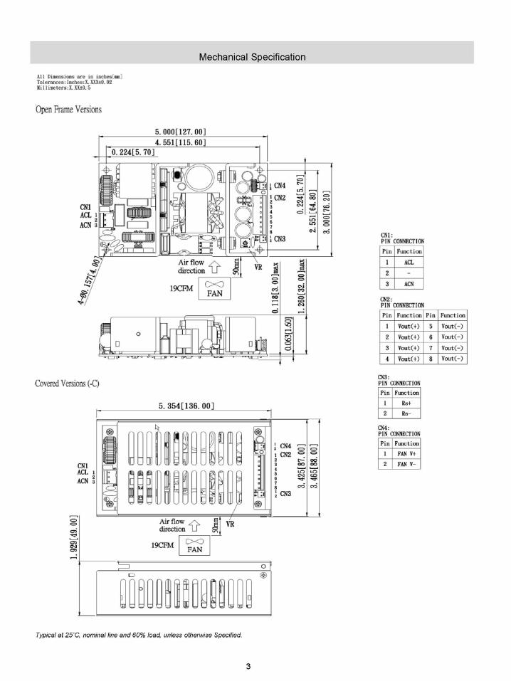
Mechanical Specification
Typical at 25˚C, nominal line and 75% load, unless otherwise Specified

1400 PROVIDENCE HIGHWAY • BUILDING 2 NORWOOD, MASSACHUSETTS 02062-5015PHONE: 781-551-5500 FAX: 781-551-5555
AC200X
SERIES
AC200X12
AC200X24
AC200X36
AC200X48
AC200X
Series Derating
Curve

AC 200 Series New Product 200 Watt Single Output U Frame
AC-DC Modules with PFC
FEATURES SPECIFICATIONS
Input Characteristics
AC Input Voltage Frequency Inrush Current EMI Isolation Leakage Current
90 ~ 264Vac 47 to 63Hz 60A Max. CISPR/FCC Class B Input to output = 4,242Vdc 3.5mA max.
Output Characteristics Total Rated Output Power Current Share Remote Voltage Sense Hold-up Time Over Voltage Protection Over Temperature Protection Short Circuit Protection
200W (with 30CFM air flow or optional fan) Single wire current sharing Compensates for wire voltage drop 16mS typ.
Recycle AC input to restart Auto Recovery Auto Recovery
Environmental Characteristics Operating Temperature Storage Temperature
0 ~ 70 degrees C 50~70 C with 2.5%/ degrees C derating
PSU will be in thermal protection for exceeding the rated power output or the operating temperature
-20 ~ 85 C Mechanical Outline
Standard U Frame 150mmx100mmx38.1mm ( 5.91”*3.94”*1.5”)
1.5” Low Profile, 4”X6” Footprint Universal Input : 90 ~ 264Vac Active PFC Meets EN61000-3-2 EMI Meets CISPR/FCC Class B High Efficiency at 80% Typical Current Share Remote Voltage Sense AC OK Signal (Logic High) DC OK Signal (Logic High) PS ON/OFF Remote Control (Inhibit PSU by adding Logic High)
NOTE 1: Optional function can be added when ordering: Top Cover with Fan (when forced air is needed) 2: Add a 0.1uF ceramic capacitor and a 47uF E.L. capacitor to output for Ripple & Noise measuring @20MHz BW. 3: Voltage accuracy is set at 60% rated load and 25℃ Ta. 4: Line regulation is measured from High Line to Low
Line with rated load. 5: Load regulation is measured at 60%±40% rated load. 6: Dimensions tolerance : +/- 1mm. 7: Connectors:
CN1(AC Input) : Molex 5273-05A or equivalent CN2(DC Output) : Molex 38700-7504 or equivalent CN6(Signals) : Molex 70247-10 or equivalent CN3,CN4,CN5(FAN) : Molex 5045-02A or equivalent With Optional Fan 150mmx101.6mmx58.5mm
( 5.91”*4”*2.3”)
BAUART
TYPEAPPROVED
GEPRUFT
. .
..
Output Output Current (A) Ripple Voltage Line Load
Model Voltage Rated Min. & Noise Accuracy Reg. Reg.
AC200-033 +3.3V 40.0 0 1% ±1% ±1% ±1%
AC200-050 +5.0V 40.0 0 1% ±1% ±1% ±1%
AC200-120 +12V 16.7 0 1% ±1% ±1% ±1%
AC200-150 +15V 13.4 0 1% ±1% ±1% ±1%
AC200-180 +18V 11.2 0 1% ±1% ±1% ±1%
AC200-240 +24V 8.4 0 1% ±1% ±1% ±1%
AC200-280 +28V 7.2 0 1% ±1% ±1% ±1%
AC200-300 +30V 6.7 0 1% ±1% ±1% ±1%
AC200-360 +36V 5.6 0 1% ±1% ±1% ±1%
AC200-480 +48V 4.2 0 1% ±1% ±1% ±1%
Typical @25℃, 230Vac and 60% rated load, unless otherwise specified.

AC 200 Series New Product 200 Watt Single Output U Frame
AC-DC Modules with PFC
DRAWINGS: (Preliminary)
CN1
Fig.1. Mechanical Outline of AC200 Unit: inch (mm)
Fig.2. Mechanical Outline of AC200-F (With Optiona1 Fan) Unit: inch (mm)
PIN CONNECTION:
PIN9: NCPIN10: NC
PIN5: +V VS
PIN7: +V CSW
PIN3: AC OK
PIN1: GND
PIN4: PS ON/OFF
PIN2: DC OK
PIN8: NC
CN6(Signals)
PIN6: +V GS
CN1 (AC Input)
PIN NO. ASSIGNMENT
1 Earth Ground
2 NC
3 Neutral
4 NC
5 Line
CN2 (DC Output, T.B.)
PIN NO. ASSIGNMENT
1 +V
2 +V
3 PWR GND
4 PWR GND
CN3,CN4,CN5 (FAN Output)
PIN NO. ASSIGNMENT
1 +12V(FAN)
2 GND(FAN)
Note: VS means Remote Sense ”+”
GS means Remote Sense “Return”
Fig.3. Output Derating Curve 2006/11/06 Ver. 19.0
0255075
100125150175200
0 10 20 30 40 50 60 70 80
Ambient Temperature (Deg.C)
Rat
ed L
oad
(W
With 30CFM Forced Air
Convection Cool

1400 PROVIDENCE HIGHWAY • BUILDING 2 NORWOOD, MASSACHUSETTS 02062-5015PHONE: 781-551-5500 FAX: 781-551-5555
AC100X
SERIES
AC100X12
AC100X15
AC100X20
AC100X24
AC100X48

AC100X
SERIES

AC100 SERIES
Rev C December 2007
ISOLATED AC-DC Converter
AC100 SERIES
APPLICATION NOTE Rev C
Page 1

AC100 SERIES
Rev C December 2007
Page 2
Content 1. INTRODUCTION 3 2. AC100 CONVERTER FEATURES 3 3. GENERAL DESCRIPTION 3 ABSOLUTE MAXIMUM RATINGS 4
5. MAIN FEATURES AND FUNCTIONS 6 5.1 Operating Temperature Range 6
5.2 Output Voltage Adjustment 6
5.3 Over Current Protection 6
5.4 Over Voltage Protection 6
5.5 V-Sense 6
6. SAFETY 6 7. APPLICATIONS 6 7.1 Power De-Rating Curves 7
7.2 Efficiency vs. Load Curves 9
7.3 Test Set-Up 11
7.4 Output Ripple and Noise Measurement 11
7.5 Output Capacitance 11
7.6 EMI 11
8. MECHANICAL OUTLINE DIAGRAMS 12 8.1 AC100 Mechanical Outline Diagrams 12 9.INSTALLATION INSTRUCTION 12 10. PART NIMBER 14
AC100 SERIES
Rev C December 2007
1. Introduction This application note describes the features and functions of Intronics power’s AC100 series of open frame, Isolated AC-DC Converters. These are highly efficient, reliable and compact, high power density, single output AC/DC converters. Ultra-high efficiency operation is achieved through the use of synchronous rectification and drive control techniques. The modules are fully protected against short circuit and over-voltage conditions. Intronics power’s world class automated manufacturing methods, together with an extensive testing and qualification program; ensure that all AC100 series converters are extremely reliable.
2. AC100 Converter Features • 100W Isolated Output • High Efficiency Up to 85% • Fixed Switching Frequency • Power factor correction Up to 0.9
• Universal Input Range • Regulated Outputs • Continuous Short Circuit Protection • 3” X 5” size • Open-Frame Type
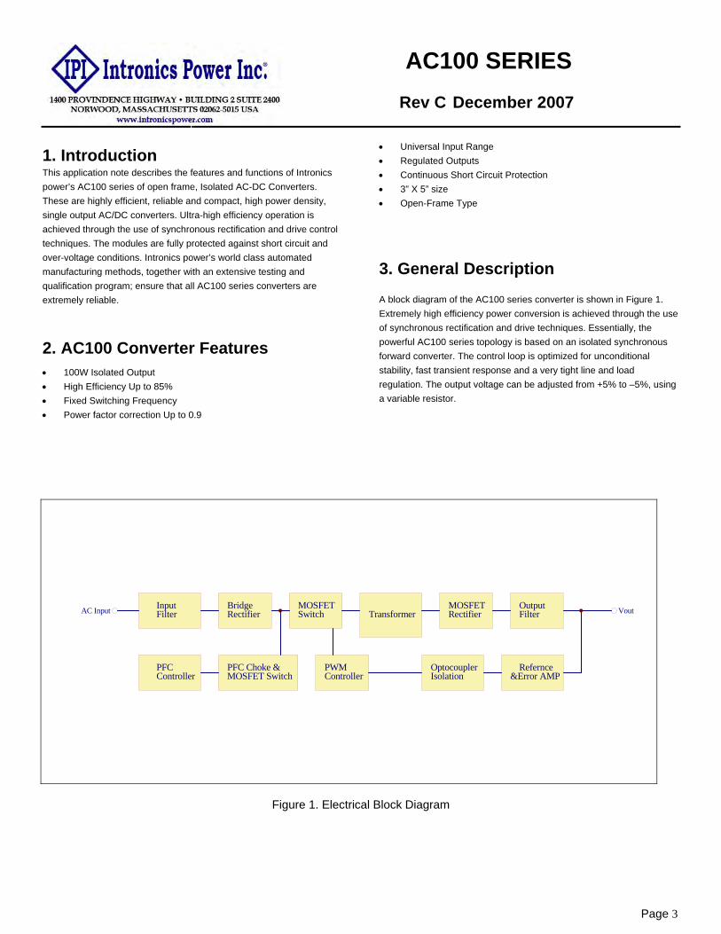
3. General Description A block diagram of the AC100 series converter is shown in Figure 1. Extremely high efficiency power conversion is achieved through the use of synchronous rectification and drive techniques. Essentially, the powerful AC100 series topology is based on an isolated synchronous forward converter. The control loop is optimized for unconditional stability, fast transient response and a very tight line and load regulation. The output voltage can be adjusted from +5% to –5%, using a variable resistor.
Figure 1. Electrical Block Diagram
InputFilter
BridgeRectifier
PFCController
PFC Choke &MOSFET Switch
PWMController
MOSFETSwitch Transformer
MOSFETRectifier
OptocouplerIsolation
Refernce&Error AMP
OutputFilter VoutAC Input
Page 3

AC100 SERIES
Rev C December 2007
Page 4
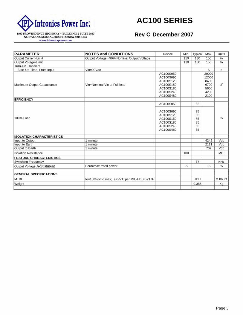
4. Technical Specifications (All specifications are typical at nominal input, full load at 25℃ unless otherwise noted.) PARAMETER NOTES and CONDITIONS Device Min. Typical Max. Units
ABSOLUTE MAXIMUM RATINGS Input Voltage
Continuous 90 264 Vdc Operating Temperature 0 +40 ℃
Storage Temperature -20 +85 ℃ Input/Output Isolation Voltage 1 minute 4242 Vdc INPUT CHARACTERISTICS Operating Voltage Range 100 240 Vac Input Frequency Range 47 63 Hz Maximum Input Current 100% Load, Vin=90Vac 1.5 A Power factor correction 100% Load, Vin=Nominal Vin 0.9
No-Load Input Power Vin=264Vac
AC100S050 AC100S090 AC100S120 AC100S150 AC100S180 AC100S240 AC100S480
7.0 6.0 5.0 5.0 5.0 5.0 4.0
W
Leakage Current 3.5 mA Inrush Current Vin=240Vac, cold start at 250C. 80 A OUTPUT CHARACTERISTIC
Output Voltage Set Point Vin=Nominal Vin , Io=Io.max, Tc=25℃
AC100S050 AC100S090 AC100S120 AC100S150 AC100S180 AC100S240 AC100S480
4.95 8.91
11.88 14.85 17.82 23.76 47.52
5.0 9.0
12.0 15.0 18.0 24.0 48.0
5.05 9.09
12.1215.1518.1824.2448.48
Vdc
Operating Output Current Range
AC100S050 AC100S090 AC100S120 AC100S150 AC100S180 AC100S240 AC100S480
20.0 11.2 8.4 6.7 5.6 4.2 2.1
A
Holdup Time Vin=115Vac 20 mS Output Voltage Regulation
Load Regulation 10% load to Full load ±1.0 %
Line Regulation Vin=high line to low line ±0.5 %
Output Voltage Ripple and Noise 20MHz bandwidth
Full load, 0.1uF ceramic and 220uF E.L capacitor AC100S050 AC100S090 AC100S120
100 90
120 mV
Peak-to-Peak
Full load, 0.1uF ceramic and 10uF E.L capacitor
AC100S150 AC100S180 AC100S240 AC100S480
150 180 240 480
mV
AC100 SERIES
Rev C December 2007
Page 5
PARAMETER NOTES and CONDITIONS Device Min. Typical Max. Units Output Current-Limit Output Voltage =90% Nominal Output Voltage 110 130 150 % Output Votage-Limit 110 130 150 % Turn-On Transient
Start-Up Time, From Input Vin=90Vac 5 s
Maximum Output Capacitance Vin=Nominal Vin at Full load
AC100S050 AC100S090 AC100S120 AC100S150 AC100S180 AC100S240 AC100S480
20000120008400 6700 5600 4200 2100
uF
EFFICIENCY AC100S050 82
100% Load
AC100S090 AC100S120 AC100S150 AC100S180 AC100S240 AC100S480
85 85 85 85 85 85
%
ISOLATION CHARACTERISTICS Input to Output 1 minute 4242 Vdc Input to Earth 1 minute 2121 Vdc Output to Earth 1 minute 707 Vdc Isolation Resistance 100 MΩ FEATURE CHARACTERISTICS Switching Frequency 67 KHz Output Voltage Adjustment Pout=max rated power -5 +5 % GENERAL SPECIFICATIONS MTBF Io=100%of Io.max;Ta=25℃ per MIL-HDBK-217F TBD M hoursWeight 0.385 Kg

AC100 SERIES
Rev C December 2007
Page 6
5. Main Features and Functions 5.1 Operating Temperature Range
Intronics power’s AC100 series converters highly efficient converter design has resulted in its ability to operate ambient temperature environment (0℃ to 40℃). Due consideration must be given to the de-rating curves when ascertaining maximum power that can be drawn from the converter. The maximum power drawn is influenced by a number of factors, such as: • Input voltage range. • Output load current. • These can be effective heat sinks for the converter.
5.2 Output Voltage Adjustment The output voltage on all models is in the range from +5% to –5% but can't exceed the watt value of the products . 5.3 Over Current Protection
All different voltage models have a full continuous short-circuit protection. The unit will auto recover once the short circuit is removed. To provide protection in a fault condition, the unit is equipped with internal over-current protection. The unit operates normally once the fault condition is removed. The power module will supply up to 150% of rated current. In the event of an over current converter will go into a hiccup mode protection.
5.4 Over Voltage Protection
All different voltage models have a full continuous over voltage protection. The power module will supply up to 150% of rated voltage. In the event of an over voltage converter will go into a hiccup mode protection.
5.5 V-Sense
V-sense measures the use as outputting the voltage. The maximum length of the sense lines is 1200mm. The min gauge wire that can be used 26AWG. If does not use and needn't need to join .
6. Safety CB Approval TUV Approval UL Approval
7. Applications

AC100 SERIES
Rev C December 2007
7.1 Power De-Rating Curves
Figure 6a. Typical Power De-rating for AC100S050 Figure 6b.Typical Power De-rating for AC100S090
Figure 6c.Typical Power De-rating for AC100S120 Figure 6d.Typical Power De-rating for AC100S150
g
0%
25%
50%
75%
100%
0 10 20 30 40 50 60 7Ambient temperature(oC)
Out
put l
oad
0%
25%
50%
75%
100%
0 10 20 30 40 50 60 7Ambient temperature(oC)
Out
put l
oad
0 0
0%
25%
50%
75%
100%
0 10 20 30 40 50 60 7Ambient temperature(oC)
Out
put l
oad
0%
25%
50%
75%
100%
0 10 20 30 40 50 60 7Ambient temperature(oC)
Out
put l
oad
0 0
Page 7

AC100 SERIES
Rev C December 2007
Figure 6g.Typical Power De-rating for AC100S180 Figure 6h.Typical Power De-rating for AC100S240
Figure 6i.Typical Power De-rating for AC100S480
0%
25%
50%
75%
100%
0 10 20 30 40 50 60 70Ambient temperature(oC)
Out
put l
oad
0%
25%
50%
75%
100%
0 10 20 30 40 50 60 7Ambient temperature(oC)
Out
put l
oad
0
g
0%
25%
50%
75%
100%
0 10 20 30 40 50 60 7Ambient temperature(oC)
Out
put l
oad
0
Page 8

AC100 SERIES
Rev C December 2007
7.2 Efficiency vs. Load Curves
AC100S050
30.0
40.0
50.0
60.0
70.0
80.0
90.0
1 2 3 4 5 6 7 8 9 10 11 12 13 14 15 16 17 18 19 20Output Current (A)
Effic
ienc
y (%
115VAC230VAC
AC100S090
50.0
55.0
60.0
65.0
70.0
75.0
80.0
85.0
90.0
95.0
1 2 3 4 5 6 7 8 9 10 11 11.2
Output Current (A)Ef
ficie
ncy
(%
115VAC
230VAC
Figure 7a. AC100S050 Figure 7b. AC100S090
AC100S120
50.055.060.065.070.075.080.085.090.095.0
0.5 1 1.5 2 2.5 3 3.5 4 4.5 5 5.5 6 6.5 7 7.5 8 8.5Output Current (A)
Effic
ienc
y (%
115VAC230VAC
AC100S150
50.0
55.0
60.0
65.0
70.0
75.0
80.0
85.0
90.0
95.0
0.5 1 1.5 2 2.5 3 3.5 4 4.5 5 5.5 6 6.5 7
Output Current (A)
Effic
ienc
y (%
)
115VAC
230VAC
Figure 7c. AC100S120 Figure 7d. AC100S150
Page 9

AC100 SERIES
Rev C December 2007
AC100S180
50.055.060.065.070.075.080.085.090.095.0
0.5 1 1.5 2 2.5 3 3.5 4 4.5 5 5.5 5.6Output Current (A)
Effic
ienc
y (%
115VAC230VAC
AC100S240
50.0
55.0
60.0
65.0
70.0
75.0
80.0
85.0
90.0
95.0
0.5 1 1.5 2 2.5 3 3.5 4 4.2Output Current (A)
Effic
ienc
y (%
115VAC
230VAC
Figure 7g. AC100S180 Figure 7h. AC100S240
AC100S480
50.0
55.0
60.0
65.0
70.0
75.0
80.0
85.0
90.0
95.0
0.25 0.5 0.75 1 1.25 1.5 1.75 2 2.1
Output Current (A)
Effic
ienc
y (%
115VAC
230VAC
Figure 7i. AC100S480
Page 10

AC100 SERIES
Rev C December 2007
7.3 Test Set-Up The basic test set-up to measure parameters such as efficiency and load regulation is shown in Figure 8. When testing the Intronics power’s AC100 series under any transient conditions please ensure that the transient response of the source is sufficient to power the equipment under test. We can calculate the • Efficiency • Load regulation and line regulation. The value of efficiency is defined as:
%100××
=Pin
IoVoη
Page 11
Where: Vo is output voltage,
Io is output current, Pin is input power,
The value of load regulation is defined as:
%100. ×−
=NL
NLFL
VVVregLoad
Where: VFL is the output voltage at full load
VNL is the output voltage at 10% load
The value of line regulation is defined as:
%100. ×
−=
LL
LLHL
VVVregLine
Where: VHL is the output voltage of maximum input voltage at full load.
VLL is the output voltage of minimum input voltage at full load.
V
A
LoadAC
Supply
+Vo
-Vo
L
N
Pin
Figure 8. AC100 Series Test Setup
7.4 Output Ripple and Noise Measurement The test set-up for noise and ripple measurements is shown in Figure 10. Measured method : Add a terminal wire is 50mmMIN that the output end needs to connect the sub length of line of one end . 1. Add a 0.1 uF ceramic capacitor and a 220 uF electrolytic capacitor
to output at 20 MHz Band Width for AC100S050 , AC100S090 and AC100S120.
2. Add a 0.1 uF ceramic capacitor and a 10 uF electrolytic capacitor to output at 20 MHz Band Width for AC100S150 , AC100S180 , AC100S240 and AC100S480.
+Vo
-Vo
L
N0.1uF
+
10uF/100V or220uF/35V
AC
Suppl
AC100
Loa
Terminal wire
Oscillosco
Figure 10. Output Voltage Ripple and Noise Measurement Set-Up
7.5 Output Capacitance Intronics power’ AC100 series converters provide unconditional stability with or without external capacitors. Intronics power’ converters are designed to work with load capacitance up-to 1000uF per amp.
7.6 EMI
Conductive EMI meets CISPR/FCC Class B

AC100 SERIES
Rev C December 2007
8. Mechanical Outline Diagrams 8.1 AC100 Mechanical Outline Diagrams
Dimensions are in millimeters Tolerance: x.x ±0.5mm, unless otherwise noted Annotations:All models height does not exceed 34mmMAX .
Page 12
for AC100S050
Figure 11. AC100 Mechanical Outline Diagram
9. Installation Instruction
Please use the mounting hold as: AC100S series : 4 holds of ψ 3.17
And insert the spacer (Maxψ 6) of height over 8mm to lift the unit .The vibration spec. is the value take when the unit is raised by 8mm spacers.

AC100 SERIES
Rev C December 2007
Please reserve 4mm space from the surfaces and the sides of PCB, especially from the solder surface, 8mm space is necessary. If the space is not enough, the specification of insulation and withstand will not be satisfied.
FG should be connected to the earth terminal of the apparatus. If not, the conducted noise and output noise will increase.
Page 13

AC100 SERIES
Rev C December 2007
10. Part Number
AC – XXX S XXX
Page 14
AC SERIES
100: Supply Max. Power
S: Single Output
050:Output Voltage 5.0 VDC 090:Output Voltage 9.0 VDC 120:Output Voltage 12 VDC 150:Output Voltage 15 VDC 180:Output Voltage 18 VDC 240:Output Voltage 24 VDC 480:Output Voltage 48 VDC
INTRONICS POWER INCORPORATED.

® 1400 PROVIDENCE HIGHWAY • BUILDING 2
NORWOOD, MASSACHUSETTS 02062-5015
AC60 Single
Rev A January 2007
AC-DC Switching Power Module
AC60 series
APPLICATION NOTE Rev A
Page 1

® 1400 PROVIDENCE HIGHWAY • BUILDING 2
NORWOOD, MASSACHUSETTS 02062-5015
AC60 Single
Rev A January 2007
Content 1. INTRODUCTION 3 2. AC60 SERIES CONVERTER FEATURES 3 3. TECHNICAL SPECIFICATIONS 4 4. MAIN FEATURES AND FUNCTIONS 5 4.1 Operating Temperature Range 5
4.3 Output Protection 5
5. SAFETY 5 6. APPLICATIONS 5 6.1 Power De-Rating Curve 5
6.2 Test Set-Up 6
6.3 Output Ripple and Noise Measurement 6
6.4 Installation Instruction 6
7. AC60 SERIES MECHANICAL OUTLINE DIAGRAMS 7 8. PART NUMBER 8
Page 2

®
1400 PROVIDENCE HIGHWAY • BUILDING 2
NORWOOD, MASSACHUSETTS 02062-5015
AC60 Single
Rev A January 2007
1. Introduction This application note describes the features and functions of Intronics AC60 series of open frame, switching AC-DC power module. These are highly efficient, reliable and compact, high power density, single output AC/DC power module. The module is fully protected against short circuit and over-voltage conditions. Intronics world class automated manufacturing methods, together with an extensive testing and qualification program; ensure that the AC60S480 power module is extremely reliable.
2. AC60 series Converter Features • 60W Isolated Output • High Efficiency Up to 88% • Fixed Switching Frequency • Universal Input Range • Regulated Output • Continuous Short Circuit Protection • 2” X 4” size, low profile • Open-Frame Type
Page 3
®
1400 PROVIDENCE HIGHWAY • BUILDING 2
NORWOOD, MASSACHUSETTS 02062-5015
AC60 Single
Rev A January 2007
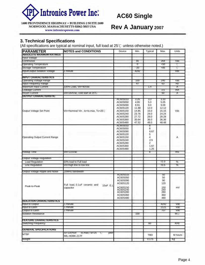
3. Technical Specifications (All specifications are typical at nominal input, full load at 25℃ unless otherwise noted.)
PARAMETER NOTES and CONDITIONS Device Min. Typical Max. Units ABSOLUTE MAXIMUM RATINGS Input Voltage Continuous 90 264 Vac Operating Temperature 0 +50 ℃
Storage Temperature -20 +85 ℃
Input/Output Isolation Voltage 1 minute 4242 Vdc
INPUT CHARACTERISTICS Operating Voltage Range 100 240 Vac Input Frequency Range 47 63 Hz Maximum Input Current 100% Load, Vin=90Vac 1.4 A Leakage Current 3.5 mA Inrush Current Vin=264Vac, cold start at 250C. 50 A OUTPUT CHARACTERISTIC
AC60S033 3.26 3.3 3.33 AC60S050 4.95 5.0 5.05 AC60S090 8.91 9.0 9.09 AC60S120 11.88 12.0 12.12
Output Voltage Set Point Vin=Nominal Vin , Io=Io.max, Tc=25℃ AC60S150 14.85 15.0 15.15 Vdc AC60S240 23.76 24.0 24.24 AC60S280 27.72 28.0 28.28 AC60S360 35.64 36.0 36.36 AC60S480 47.52 48.0 48.48 AC60S033 8 AC60S050 8 AC60S090 6.67 AC60S120 5
Operating Output Current Range AC60S150 4 A AC60S240 2.5 AC60S280 2 AC60S360 1.67 AC60S480 1.25
Holdup Time Vin=115Vac 8 mS
Output Voltage Regulation Load Regulation 10% load to Full load ±1.0 % Line Regulation Vin=high line to low line ±0.5 %
Output Voltage Ripple and Noise
Peak-to-Peak ISOLATION CHARACTERISTICS Input to Output Input to Earth Output to Earth
20MHz bandwidth
Full load, 0.1uF ceramic and capacitor
1 minute 1 minute 1 minute
AC60S033 50 AC60S050 50 AC60S090 90 AC60S120 120
10uF E.L AC60S150 150 mV AC60S240 240 AC60S280 280 AC60S360 360 AC60S480 480
4242 Vdc 2121 Vdc 707 Vdc
Isolation Resistance 100 MΩ
FEATURE CHARACTERISTICS Switching Frequency 60 KHz GENERAL SPECIFICATIONS
MTBF
Weight
Io=100%of Io.max;Ta=25 MIL-HDBK-217F
℃ per TBD M hours 0.175 Kg
Page 4

®
1400 PROVIDENCE HIGHWAY • BUILDING 2
NORWOOD, MASSACHUSETTS 02062-5015
AC60 Single
R ev A January 2007
4. Main Features and Functions 4.1 Operating Temperature Range Intronics AC60 series power modules, which highly efficient design, has resulted in its ability to operate ambient temperature environment (0℃ to 50℃). Due to consideration must be given to the de-rating curves when ascertaining maximum power that can be drawn from the power module. The maximum power drawn is influenced by a number of factors, such as: • Input voltage range. • Output load current. • These can be effective heat sinks for the power module.
4.3 Output Protection The power modules provide a full continuous short-circuit protection. The unit will auto recover once the short circuit is removed. To provide protection in a fault condition, the unit is equipped with internal over-current protection. The unit will operate normally once the fault condition is removed. The power module will go to hiccup mode if the output current or voltage is set from 110% to 150% of rated current or voltage.
5. Safety CB Approval TUV Approval UL Approval CE Approval
6. Applications
6.1 Power De-Rating Curve
Page 5
®
1400 PROVIDENCE HIGHWAY • BUILDING 2
NORWOOD, MASSACHUSETTS 02062-5015
AC60 Single
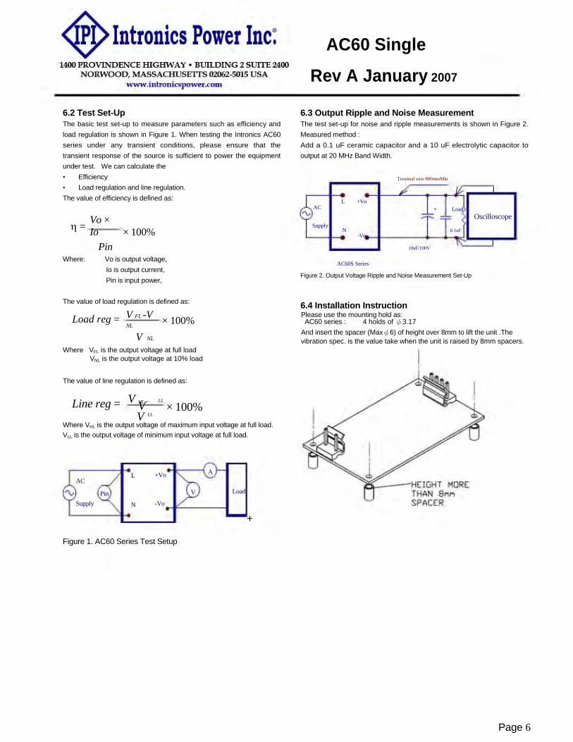
Rev A January 2007 6.2 Test Set-Up The basic test set-up to measure parameters such as efficiency and load regulation is shown in Figure 1. When testing the Intronics AC60 series under any transient conditions, please ensure that the transient response of the source is sufficient to power the equipment under test. We can calculate the • Efficiency • Load regulation and line regulation. The value of efficiency is defined as:
6.3 Output Ripple and Noise Measurement The test set-up for noise and ripple measurements is shown in Figure 2. Measured method : Add a 0.1 uF ceramic capacitor and a 10 uF electrolytic capacitor to output at 20 MHz Band Width.
Terminal wire 800mmMin
L +Vo
η = Vo × Io
Pin
AC
Supply × 100%
+ Load Oscilloscope
N 0.1uF -Vo
10uF/100V
Where: Vo is output voltage, Io is output current, Pin is input power,
The value of load regulation is defined as:
AC60S Series
Figure 2. Output Voltage Ripple and Noise Measurement Set-Up
6.4 Installation Instruction Load reg = V FL -V
NL
V NL
Please use the mounting hold as: × 100% AC60 series : 4 holds of ψ3.17
And insert the spacer (Maxψ6) of height over 8mm to lift the unit .The vibration spec. is the value take when the unit is raised by 8mm spacers.
Where VFL is the output voltage at full load VNL is the output voltage at 10% load
The value of line regulation is defined as:
Line reg = V
HL − V
LL
× 100% V LL
Where VHL is the output voltage of maximum input voltage at full load. VLL is the output voltage of minimum input voltage at full load.
L +Vo A AC
Pin V Load
Supply N -Vo
+ Figure 1. AC60 Series Test Setup
Page 6

®
1400 PROVIDENCE HIGHWAY • BUILDING 2
NORWOOD, MASSACHUSETTS 02062-5015
AC60 Single
Rev A January 2007
7.AC60 Series Mechanical Outline
Please reserve 4mm space from the surfaces and the sides of PCB, especially from the solder surface, 8mm space is necessary. If the space is not enough, the specification of insulation and withstand will not be satisfied.
FG should be connected to the earth terminal of the apparatus. If not, the conducted noise and output noise will increase.
Diagrams Dimensions are in millimeters Tolerance: x.x ±0.5mm, unless otherwise noted Annotations:All models height does not exceed 34mmMAX .
Figure 6. AC60 series Mechanical Outline Diagram
Page 7

®
1400 PROVIDENCE HIGHWAY • BUILDING 2
NORWOOD, MASSACHUSETTS 02062-5015
AC60 Single
Rev A January 2007
8. Part Number
AC XX S XXX AC SERIES
60:
Supply Max. Power S:Single Output
• 033:Output Voltage3.3 VDC • 050:Output Voltage 5.0 VDC • 090:Output Voltage 9.0 VDC • 120:Output Voltage 12 VDC • 150:Output Voltage 15 VDC • 240:Output Voltage 24 VDC • 280:Output Voltage 28 VDC • 360:Output Voltage 36 VDC • 480:Output Voltage 48 VDC
Page 8

AC10 / 15AC10 / 15


