68
AC 100 V 30 W - 200 W, AC 200 V 30 W - 25kW Ver.2
AC100 V 30 W-200 W, AC 200 V 30 W-25kW
Ver.2
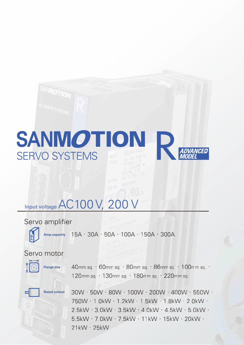
Input voltage AC100 V, 200 V Servo amplifier
111155A・3000A・5500AAAA・・1100000AAAA・・・・11155000A・33333000000AAA
Servo motor
440mm sq.・6660mmmm sssqqq.・8800mmm sqqq.・888666mmmmmmmm sssqq.・・・11000000mmmm sq.・120mm sq..・・1133300mmmm sssqq.・11888000mmmm sssqq.・22222222000mmmmm sqq..
30W・50000WWW・80W・100W・220000000WW・・440000WWW・550W・750W・1.0kW・1.2kW・1.5kkWWWW・111.8kW・2.0kW・2.5kW・3.0kW・3.5kW・444.000kW・4.5kW・5.0kW・5.5kWW・7.0kW・7.555kkkWWW・11kW・15kW・20kW・21kWWW・25kW
Amp.capacity
Flange size
Rated output
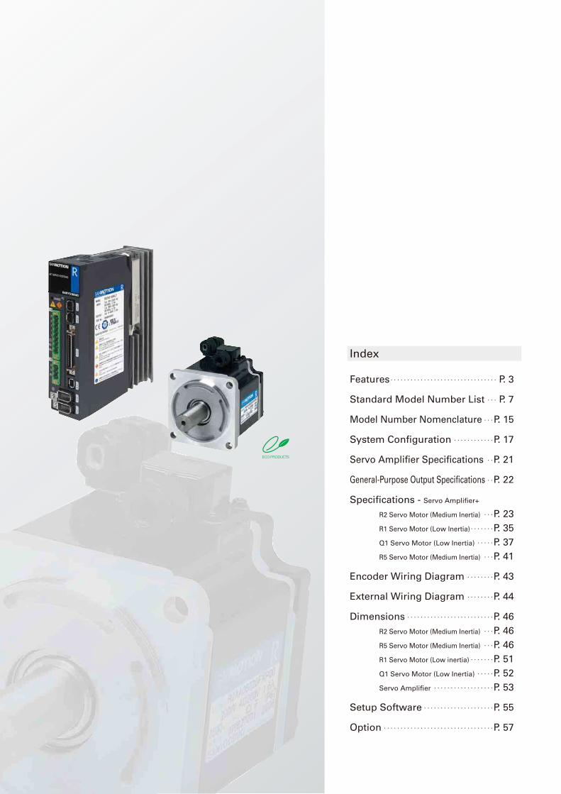
Index
Features・・・・・・・・・・・・・・・・・・・・・・・・・・・・・・・・ P. 3
Standard Model Number List ・・・ P. 7
Model Number Nomenclature ・・・P. 15
System Configuration ・・・・・・・・・・・・P. 17
Servo Amplifier Specifications ・・P. 21
General-Purpose Output Specifications ・・P. 22
Specifications - Servo Amplifier+
R2 Servo Motor (Medium Inertia) ・・・P. 23
R1 Servo Motor (Low Inertia)・・・・・・・P. 35
Q1 Servo Motor (Low Inertia) ・・・・・P. 37
R5 Servo Motor (Medium Inertia) ・・・P. 41
Encoder Wiring Diagram ・・・・・・・・P. 43
External Wiring Diagram ・・・・・・・・P. 44
Dimensions ・・・・・・・・・・・・・・・・・・・・・・・・・・P. 46
R2 Servo Motor (Medium Inertia) ・・・P. 46
R5 Servo Motor (Medium Inertia) ・・・P. 46
R1 Servo Motor (Low inertia)・・・・・・・P. 51
Q1 Servo Motor (Low Inertia) ・・・・・P. 52
Servo Amplifier ・・・・・・・・・・・・・・・・・・P. 53
Setup Software ・・・・・・・・・・・・・・・・・・・・・P. 55
Option ・・・・・・・・・・・・・・・・・・・・・・・・・・・・・・・・・P. 57
3
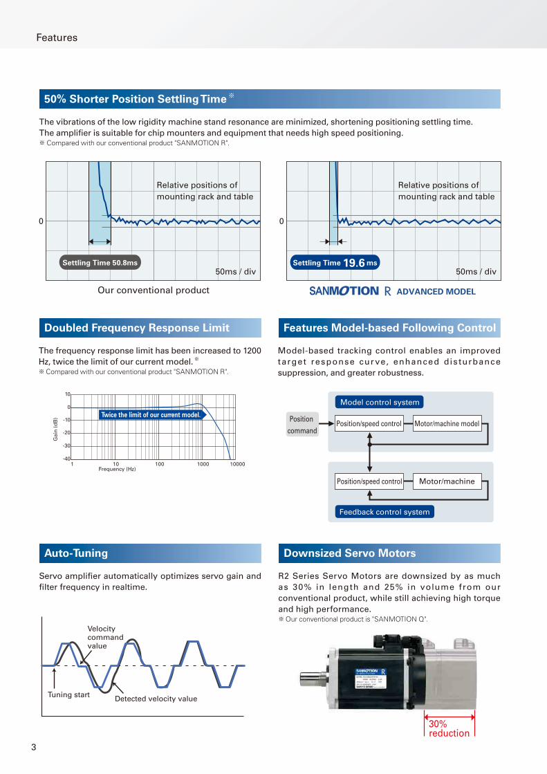
50% Shorter Position Settling Time※
Doubled Frequency Response Limit Features Model-based Following Control
The vibrations of the low rigidity machine stand resonance are minimized, shortening positioning settling time.
The amplifi er is suitable for chip mounters and equipment that needs high speed positioning.※ Compared with our conventional product "SANMOTION R".
The frequency response limit has been increased to 1200
Hz, twice the limit of our current model.※
※Compared with our conventional product "SANMOTION R".
Model-based tracking control enables an improved
target response cur ve, enhanced dis turbance
suppression, and greater robustness.
0
Relative positions of
mounting rack and table
Our conventional product ADVANCED MODEL
50ms / div
0
Relative positions of
mounting rack and table
50ms / divSettling Time 19.6 msSettling Time 50.8ms
Auto-Tuning
Servo amplifi er automatically optimizes servo gain and
fi lter frequency in realtime.
Tuning startDetected velocity value
Velocity command value
Downsized Servo Motors
R2 Series Servo Motors are downsized by as much
as 30% in length and 25% in volume from our
conventional product, while still achieving high torque
and high performance.※Our conventional product is "SANMOTION Q".
30% reduction
Features
10 100 10001 10000
Ga
in (
dB
)
-20
-30
-40
-10
0
10
Frequency (Hz)
Twice the limit of our current model.
Position/speed controlPosition
commandMotor/machine model
Position/speed control Motor/machine
Model control system
Feedback control system
4
Featu
res a
nd
Fu
ncti
on
sM
odel
No.
Lis
t
・Mod
el
Num
ber
Nom
encl
atur
eS
tan
dard
S
pecifi
cati
on
sE
nco
der
Wir
ing
D
iag
ram
Exte
rnal W
irin
g
Dia
gra
mD
imen
sio
ns
Setu
p S
oft
ware
Op
tio
nS
yste
m
Co
nfi
gu
rati
on
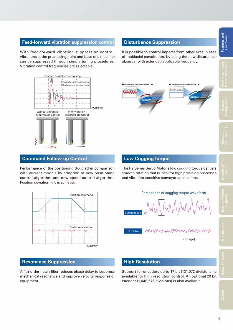
Resonance Suppression
A 4th-order notch fi lter reduces phase delay to suppress
mechanical resonance and improve velocity response of
equipment.
Feed-forward vibration suppression control
With feed-forward vibration suppression control,
vibrations at the processing point and base of a machine
can be suppressed through simple tuning procedures.
Vibration control frequencies are selectable.
Position deviation during stop
With vibration suppression control
Without vibration suppression control
100ms/div
With vibration
suppression controlWithout vibration
suppression control
Disturbance Suppression
It is possible to control impacts from other axes in case
of multiaxial constitution, by using the new disturbance
observer with extended applicable frequency.
Oscillation waveform of direct drive section
Oscillation waveform of direct drive section
Disturbance observer function OFF Disturbance observer function ON
DisturbanceDisturbance
Command Follow-up Control
Performance of the positioning doubled in comparison
with current models by adoption of new positioning
control algorithm and new speed control algorithm.
Position deviation≒ 0 is achieved.
Position deviation
Position command
20ms/div
Low Cogging Torque
The R2 Series Servo Motor's low cogging torque delivers
smooth rotation that is ideal for high precision processes
and vibration-sensitive conveyor applications.
High Resolution
Support for encoders up to 17 bit (131,072 divisions) is
available for high resolution control. An optional 20 bit
encoder (1,048,576 divisions) is also available.
R motor
Current model
Comparison of cogging torque waveform
(Image)
5
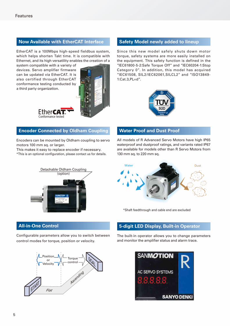
Encoder Connected by Oldham Coupling
Encoders can be mounted by Oldham coupling to servo
motors 100 mm sq. or larger.
This makes it easy to replace encoder if necessary.
*This is an optional confi guration, please contact us for details.
Water Proof and Dust Proof
All models of R Advanced Servo Motors have high IP65
waterproof and dustproof ratings, and variants rated IP67
are available for models other than R Servo Motors from
130 mm sq. to 220 mm sq.
*Shaft feedthrough and cable end are excluded
Water Dust
All-in-One Control
Confi gurable parameters allow you to switch between
control modes for torque, position or velocity.
START
GOAL
Position
or
Velocity
Torque
control
Flat
Ascen
ding
5-digit LED Display, Built-in Operator
The built-in operator allows you to change parameters
and monitor the amplifi er status and alarm trace.
Now Available with EtherCAT Interface
EtherCAT is a 100Mbps high-speed fieldbus system,
which helps shorten Takt time. It is compatible with
Ethernet, and its high versatility enables the creation of a
system compatible with a variety of
devices. Servo amplifier firmware
can be updated via EtherCAT. It is
also certified through EtherCAT
conformance testing conducted by
a third party organization.
Features
Safety Model newly added to lineup
Since this new model safely shuts down motor
torque, safety systems are more easily installed on
the equipment. This safety function is defined in the
”IEC61800-5-2:Safe Torque Off” and ”IEC60204-1:Stop
Category 0”. In addition, this model has acquired
”IEC61508, SIL2/IEC62061,SILCL2” and ”ISO13849-
1:Cat.3,PL=d”.
Detachable Oldham Coupling(option)
6
Featu
res a
nd
Fu
ncti
on
sM
odel
No.
Lis
t
・Mod
el
Num
ber
Nom
encl
atur
eS
tan
dard
S
pecifi
cati
on
sE
nco
der
Wir
ing
D
iag
ram
Exte
rnal W
irin
g
Dia
gra
mD
imen
sio
ns
Setu
p S
oft
ware
Op
tio
nS
yste
m
Co
nfi
gu
rati
on
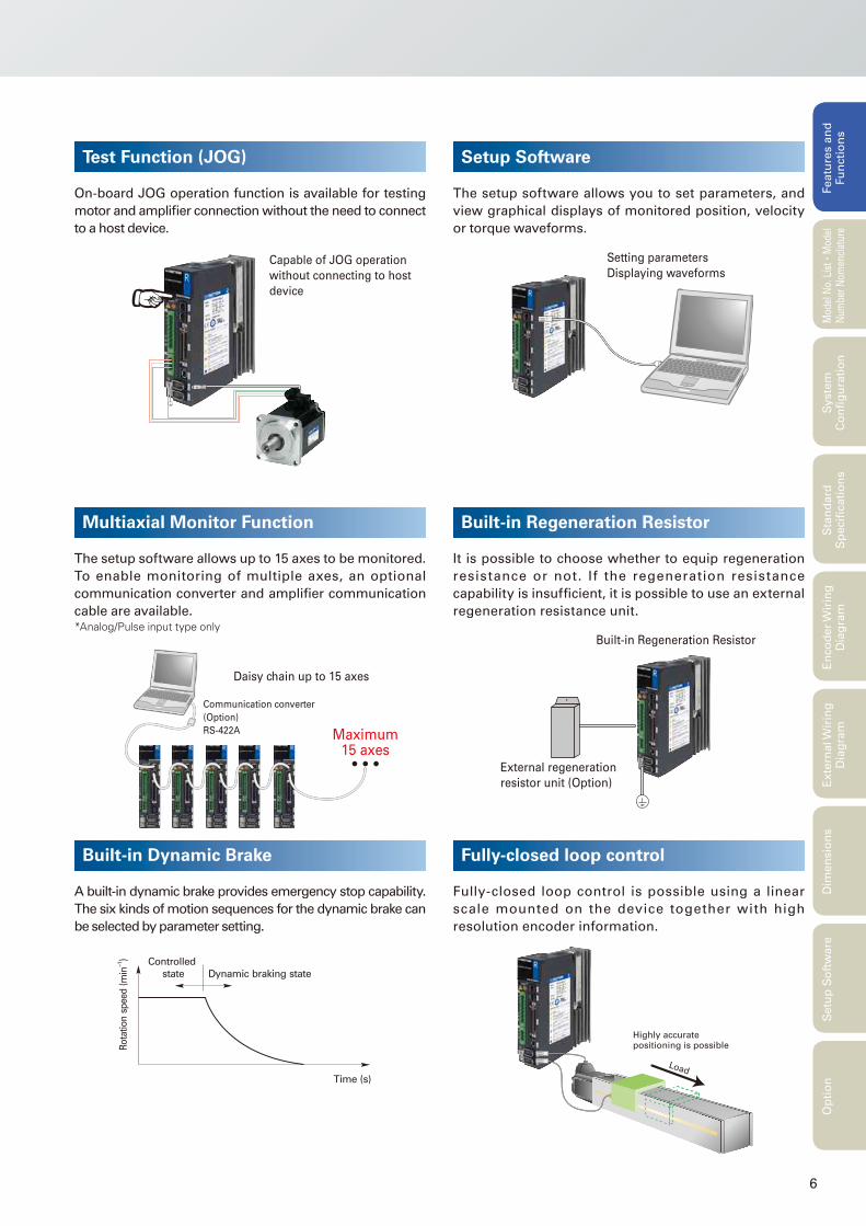
Test Function (JOG)
On-board JOG operation function is available for testing
motor and amplifi er connection without the need to connect
to a host device.
Capable of JOG operation
without connecting to host
device
Setup Software
The setup software allows you to set parameters, and
view graphical displays of monitored position, velocity
or torque waveforms.
Multiaxial Monitor Function
The setup software allows up to 15 axes to be monitored.
To enable monitoring of multiple axes, an optional
communication converter and amplifi er communication
cable are available.*Analog/Pulse input type only
Setting parameters
Displaying waveforms
Daisy chain up to 15 axes
Communication converter
(Option)
RS-422A Maximum15 axes
Built-in Regeneration Resistor
It is possible to choose whether to equip regeneration
resistance or not. If the regeneration resistance
capability is insuffi cient, it is possible to use an external
regeneration resistance unit.
Built-in Dynamic Brake
A built-in dynamic brake provides emergency stop capability.
The six kinds of motion sequences for the dynamic brake can
be selected by parameter setting.
Built-in Regeneration Resistor
External regeneration
resistor unit (Option)
Ro
tatio
n s
peed
(m
in−1)
Time (s)
Controlled
state Dynamic braking state
Fully-closed loop control
Fully-closed loop control is possible using a linear
scale mounted on the device together with high
resolution encoder information.
Load
Highly accurate positioning is possible
7
Standard Model Number List
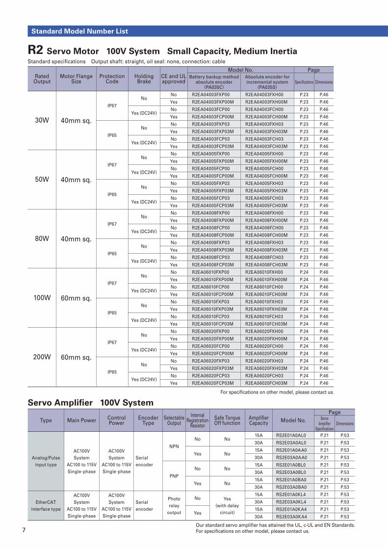
Servo Amplifi er 100V System
Type Main PowerControl Power
Encoder Type
Selectable Output
Internal Registration
Resistor
Safe Torque Off function
Amplifi er Capacity
Model No.
PageServo
Amplifi er Specifi cations
Dimensions
Analog/Pulse
input type
AC100V
System
AC100 to 115V
Single-phase
AC100V
System
AC100 to 115V
Single-phase
Serial
encoder
NPN
No No15A RS2E01A0AL0 P.21 P.53
30A RS2E03A0AL0 P.21 P.53
Yes No15A RS2E01A0AA0 P.21 P.53
30A RS2E03A0AA0 P.21 P.53
PNP
No No15A RS2E01A0BL0 P.21 P.53
30A RS2E03A0BL0 P.21 P.53
Yes No15A RS2E01A0BA0 P.21 P.53
30A RS2E03A0BA0 P.21 P.53
EtherCAT
interface type
AC100V
System
AC100 to 115V
Single-phase
AC100V
System
AC100 to 115V
Single-phase
Serial
encoder
Photo
relay
output
No Yes
(with delay
circuit)
15A RS2E01A0KL4 P.21 P.53
30A RS2E03A0KL4 P.21 P.53
Yes15A RS2E01A0KA4 P.21 P.53
30A RS2E03A0KA4 P.21 P.53
Our standard servo amplifi er has attained the UL, c-UL and EN Standards.
For specifi cations on other model, please contact us.
For specifi cations on other model, please contact us.
R2 Servo Motor 100V System Small Capacity, Medium Inertia Standard specifi cations Output shaft: straight, oil seal: none, connection: cable
Rated Output
Motor Flange Size
Protection Code
Holding Brake
CE and ULapproved
Model No. Page
Battery backup methodabsolute encoder(PA035C)
Absolute encoder forincremental system
(PA035S)Specifi cations Dimensions
30W 40mm sq.
IP67
NoNo R2EA04003FXP00 R2EA04003FXH00 P.23 P.46
Yes R2EA04003FXP00M R2EA04003FXH00M P.23 P.46
Yes (DC24V)No R2EA04003FCP00 R2EA04003FCH00 P.23 P.46
Yes R2EA04003FCP00M R2EA04003FCH00M P.23 P.46
IP65
NoNo R2EA04003FXP03 R2EA04003FXH03 P.23 P.46
Yes R2EA04003FXP03M R2EA04003FXH03M P.23 P.46
Yes (DC24V)No R2EA04003FCP03 R2EA04003FCH03 P.23 P.46
Yes R2EA04003FCP03M R2EA04003FCH03M P.23 P.46
50W 40mm sq.
IP67
NoNo R2EA04005FXP00 R2EA04005FXH00 P.23 P.46
Yes R2EA04005FXP00M R2EA04005FXH00M P.23 P.46
Yes (DC24V)No R2EA04005FCP00 R2EA04005FCH00 P.23 P.46
Yes R2EA04005FCP00M R2EA04005FCH00M P.23 P.46
IP65
NoNo R2EA04005FXP03 R2EA04005FXH03 P.23 P.46
Yes R2EA04005FXP03M R2EA04005FXH03M P.23 P.46
Yes (DC24V)No R2EA04005FCP03 R2EA04005FCH03 P.23 P.46
Yes R2EA04005FCP03M R2EA04005FCH03M P.23 P.46
80W 40mm sq.
IP67
NoNo R2EA04008FXP00 R2EA04008FXH00 P.23 P.46
Yes R2EA04008FXP00M R2EA04008FXH00M P.23 P.46
Yes (DC24V)No R2EA04008FCP00 R2EA04008FCH00 P.23 P.46
Yes R2EA04008FCP00M R2EA04008FCH00M P.23 P.46
IP65
NoNo R2EA04008FXP03 R2EA04008FXH03 P.23 P.46
Yes R2EA04008FXP03M R2EA04008FXH03M P.23 P.46
Yes (DC24V)No R2EA04008FCP03 R2EA04008FCH03 P.23 P.46
Yes R2EA04008FCP03M R2EA04008FCH03M P.23 P.46
100W 60mm sq.
IP67
NoNo R2EA06010FXP00 R2EA06010FXH00 P.24 P.46
Yes R2EA06010FXP00M R2EA06010FXH00M P.24 P.46
Yes (DC24V)No R2EA06010FCP00 R2EA06010FCH00 P.24 P.46
Yes R2EA06010FCP00M R2EA06010FCH00M P.24 P.46
IP65
NoNo R2EA06010FXP03 R2EA06010FXH03 P.24 P.46
Yes R2EA06010FXP03M R2EA06010FXH03M P.24 P.46
Yes (DC24V)No R2EA06010FCP03 R2EA06010FCH03 P.24 P.46
Yes R2EA06010FCP03M R2EA06010FCH03M P.24 P.46
200W 60mm sq.
IP67
NoNo R2EA06020FXP00 R2EA06020FXH00 P.24 P.46
Yes R2EA06020FXP00M R2EA06020FXH00M P.24 P.46
Yes (DC24V)No R2EA06020FCP00 R2EA06020FCH00 P.24 P.46
Yes R2EA06020FCP00M R2EA06020FCH00M P.24 P.46
IP65
NoNo R2EA06020FXP03 R2EA06020FXH03 P.24 P.46
Yes R2EA06020FXP03M R2EA06020FXH03M P.24 P.46
Yes (DC24V)No R2EA06020FCP03 R2EA06020FCH03 P.24 P.46
Yes R2EA06020FCP03M R2EA06020FCH03M P.24 P.46
8
Featu
res a
nd
Fu
ncti
on
sM
odel
No.
Lis
t
・Mod
el
Num
ber
Nom
encl
atur
eS
tan
dard
S
pecifi
cati
on
sE
nco
der
Wir
ing
D
iag
ram
Exte
rnal W
irin
g
Dia
gra
mD
imen
sio
ns
Setu
p S
oft
ware
Op
tio
nS
yste
m
Co
nfi
gu
rati
on
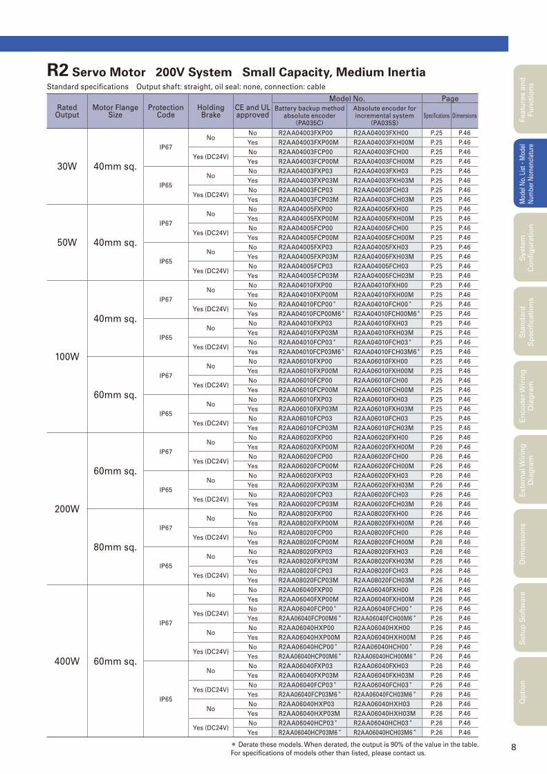
* Derate these models. When derated, the output is 90% of the value in the table.
For specifi cations of models other than listed, please contact us.
R2 Servo Motor 200V System Small Capacity, Medium Inertia Standard specifi cations Output shaft: straight, oil seal: none, connection: cable
Rated Output
Motor Flange Size
Protection Code
Holding Brake
CE and ULapproved
Model No. Page
Battery backup methodabsolute encoder(PA035C)
Absolute encoder forincremental system
(PA035S)Specifi cations Dimensions
30W 40mm sq.
IP67
NoNo R2AA04003FXP00 R2AA04003FXH00 P.25 P.46
Yes R2AA04003FXP00M R2AA04003FXH00M P.25 P.46
Yes (DC24V)No R2AA04003FCP00 R2AA04003FCH00 P.25 P.46
Yes R2AA04003FCP00M R2AA04003FCH00M P.25 P.46
IP65
NoNo R2AA04003FXP03 R2AA04003FXH03 P.25 P.46
Yes R2AA04003FXP03M R2AA04003FXH03M P.25 P.46
Yes (DC24V)No R2AA04003FCP03 R2AA04003FCH03 P.25 P.46
Yes R2AA04003FCP03M R2AA04003FCH03M P.25 P.46
50W 40mm sq.
IP67
NoNo R2AA04005FXP00 R2AA04005FXH00 P.25 P.46
Yes R2AA04005FXP00M R2AA04005FXH00M P.25 P.46
Yes (DC24V)No R2AA04005FCP00 R2AA04005FCH00 P.25 P.46
Yes R2AA04005FCP00M R2AA04005FCH00M P.25 P.46
IP65
NoNo R2AA04005FXP03 R2AA04005FXH03 P.25 P.46
Yes R2AA04005FXP03M R2AA04005FXH03M P.25 P.46
Yes (DC24V)No R2AA04005FCP03 R2AA04005FCH03 P.25 P.46
Yes R2AA04005FCP03M R2AA04005FCH03M P.25 P.46
100W
40mm sq.
IP67
NoNo R2AA04010FXP00 R2AA04010FXH00 P.25 P.46
Yes R2AA04010FXP00M R2AA04010FXH00M P.25 P.46
Yes (DC24V)No R2AA04010FCP00* R2AA04010FCH00* P.25 P.46
Yes R2AA04010FCP00M6* R2AA04010FCH00M6* P.25 P.46
IP65
NoNo R2AA04010FXP03 R2AA04010FXH03 P.25 P.46
Yes R2AA04010FXP03M R2AA04010FXH03M P.25 P.46
Yes (DC24V)No R2AA04010FCP03* R2AA04010FCH03* P.25 P.46
Yes R2AA04010FCP03M6* R2AA04010FCH03M6* P.25 P.46
60mm sq.
IP67
NoNo R2AA06010FXP00 R2AA06010FXH00 P.25 P.46
Yes R2AA06010FXP00M R2AA06010FXH00M P.25 P.46
Yes (DC24V)No R2AA06010FCP00 R2AA06010FCH00 P.25 P.46
Yes R2AA06010FCP00M R2AA06010FCH00M P.25 P.46
IP65
NoNo R2AA06010FXP03 R2AA06010FXH03 P.25 P.46
Yes R2AA06010FXP03M R2AA06010FXH03M P.25 P.46
Yes (DC24V)No R2AA06010FCP03 R2AA06010FCH03 P.25 P.46
Yes R2AA06010FCP03M R2AA06010FCH03M P.25 P.46
200W
60mm sq.
IP67
NoNo R2AA06020FXP00 R2AA06020FXH00 P.26 P.46
Yes R2AA06020FXP00M R2AA06020FXH00M P.26 P.46
Yes (DC24V)No R2AA06020FCP00 R2AA06020FCH00 P.26 P.46
Yes R2AA06020FCP00M R2AA06020FCH00M P.26 P.46
IP65
NoNo R2AA06020FXP03 R2AA06020FXH03 P.26 P.46
Yes R2AA06020FXP03M R2AA06020FXH03M P.26 P.46
Yes (DC24V)No R2AA06020FCP03 R2AA06020FCH03 P.26 P.46
Yes R2AA06020FCP03M R2AA06020FCH03M P.26 P.46
80mm sq.
IP67
NoNo R2AA08020FXP00 R2AA08020FXH00 P.26 P.46
Yes R2AA08020FXP00M R2AA08020FXH00M P.26 P.46
Yes (DC24V)No R2AA08020FCP00 R2AA08020FCH00 P.26 P.46
Yes R2AA08020FCP00M R2AA08020FCH00M P.26 P.46
IP65
NoNo R2AA08020FXP03 R2AA08020FXH03 P.26 P.46
Yes R2AA08020FXP03M R2AA08020FXH03M P.26 P.46
Yes (DC24V)No R2AA08020FCP03 R2AA08020FCH03 P.26 P.46
Yes R2AA08020FCP03M R2AA08020FCH03M P.26 P.46
400W 60mm sq.
IP67
NoNo R2AA06040FXP00 R2AA06040FXH00 P.26 P.46
Yes R2AA06040FXP00M R2AA06040FXH00M P.26 P.46
Yes (DC24V)No R2AA06040FCP00* R2AA06040FCH00* P.26 P.46
Yes R2AA06040FCP00M6* R2AA06040FCH00M6* P.26 P.46
NoNo R2AA06040HXP00 R2AA06040HXH00 P.26 P.46
Yes R2AA06040HXP00M R2AA06040HXH00M P.26 P.46
Yes (DC24V)No R2AA06040HCP00* R2AA06040HCH00* P.26 P.46
Yes R2AA06040HCP00M6* R2AA06040HCH00M6* P.26 P.46
IP65
NoNo R2AA06040FXP03 R2AA06040FXH03 P.26 P.46
Yes R2AA06040FXP03M R2AA06040FXH03M P.26 P.46
Yes (DC24V)No R2AA06040FCP03* R2AA06040FCH03* P.26 P.46
Yes R2AA06040FCP03M6* R2AA06040FCH03M6* P.26 P.46
NoNo R2AA06040HXP03 R2AA06040HXH03 P.26 P.46
Yes R2AA06040HXP03M R2AA06040HXH03M P.26 P.46
Yes (DC24V)No R2AA06040HCP03* R2AA06040HCH03* P.26 P.46
Yes R2AA06040HCP03M6* R2AA06040HCH03M6* P.26 P.46
9
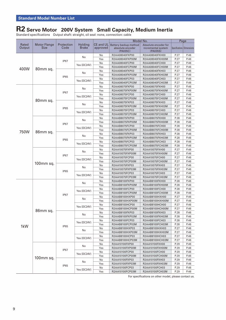
Standard Model Number List
For specifi cations on other model, please contact us.
Rated Output
Motor Flange Size
Protection Code
Holding Brake
CE and ULapproved
Model No. Page
Battery backup methodabsolute encoder(PA035C)
Absolute encoder forincremental system
(PA035S)Specifi cations Dimensions
400W 80mm sq.
IP67
NoNo R2AA08040FXP00 R2AA08040FXH00 P.27 P.46
Yes R2AA08040FXP00M R2AA08040FXH00M P.27 P.46
Yes (DC24V)No R2AA08040FCP00 R2AA08040FCH00 P.27 P.46
Yes R2AA08040FCP00M R2AA08040FCH00M P.27 P.46
IP65
NoNo R2AA08040FXP03 R2AA08040FXH03 P.27 P.46
Yes R2AA08040FXP03M R2AA08040FXH03M P.27 P.46
Yes (DC24V)No R2AA08040FCP03 R2AA08040FCH03 P.27 P.46
Yes R2AA08040FCP03M R2AA08040FCH03M P.27 P.46
750W
80mm sq.
IP67
NoNo R2AA08075FXP00 R2AA08075FXH00 P.27 P.46
Yes R2AA08075FXP00M R2AA08075FXH00M P.27 P.46
Yes (DC24V)No R2AA08075FCP00 R2AA08075FCH00 P.27 P.46
Yes R2AA08075FCP00M R2AA08075FCH00M P.27 P.46
IP65
NoNo R2AA08075FXP03 R2AA08075FXH03 P.27 P.46
Yes R2AA08075FXP03M R2AA08075FXH03M P.27 P.46
Yes (DC24V)No R2AA08075FCP03 R2AA08075FCH03 P.27 P.46
Yes R2AA08075FCP03M R2AA08075FCH03M P.27 P.46
86mm sq.
IP67
NoNo R2AAB8075FXP00 R2AAB8075FXH00 P.28 P.46
Yes R2AAB8075FXP00M R2AAB8075FXH00M P.28 P.46
Yes (DC24V)No R2AAB8075FCP00 R2AAB8075FCH00 P.28 P.46
Yes R2AAB8075FCP00M R2AAB8075FCH00M P.28 P.46
IP65
NoNo R2AAB8075FXP03 R2AAB8075FXH03 P.28 P.46
Yes R2AAB8075FXP03M R2AAB8075FXH03M P.28 P.46
Yes (DC24V)No R2AAB8075FCP03 R2AAB8075FCH03 P.28 P.46
Yes R2AAB8075FCP03M R2AAB8075FCH03M P.28 P.46
100mm sq.
IP67
NoNo R2AA10075FXP00 R2AA10075FXH00 P.27 P.46
Yes R2AA10075FXP00M R2AA10075FXH00M P.27 P.46
Yes (DC24V)No R2AA10075FCP00 R2AA10075FCH00 P.27 P.46
Yes R2AA10075FCP00M R2AA10075FCH00M P.27 P.46
IP65
NoNo R2AA10075FXP03 R2AA10075FXH03 P.27 P.46
Yes R2AA10075FXP03M R2AA10075FXH03M P.27 P.46
Yes (DC24V)No R2AA10075FCP03 R2AA10075FCH03 P.27 P.46
Yes R2AA10075FCP03M R2AA10075FCH03M P.27 P.46
1kW
86mm sq.
IP67
NoNo R2AAB8100FXP00 R2AAB8100FXH00 P.28 P.46
Yes R2AAB8100FXP00M R2AAB8100FXH00M P.28 P.46
Yes (DC24V)No R2AAB8100FCP00 R2AAB8100FCH00 P.28 P.46
Yes R2AAB8100FCP00M R2AAB8100FCH00M P.28 P.46
NoNo R2AAB8100HXP00 R2AAB8100HXH00 P.27 P.46
Yes R2AAB8100HXP00M R2AAB8100HXH00M P.27 P.46
Yes (DC24V)No R2AAB8100HCP00 R2AAB8100HCH00 P.27 P.46
Yes R2AAB8100HCP00M R2AAB8100HCH00M P.27 P.46
IP65
NoNo R2AAB8100FXP03 R2AAB8100FXH03 P.28 P.46
Yes R2AAB8100FXP03M R2AAB8100FXH03M P.28 P.46
Yes (DC24V)No R2AAB8100FCP03 R2AAB8100FCH03 P.28 P.46
Yes R2AAB8100FCP03M R2AAB8100FCH03M P.28 P.46
NoNo R2AAB8100HXP03 R2AAB8100HXH03 P.27 P.46
Yes R2AAB8100HXP03M R2AAB8100HXH03M P.27 P.46
Yes (DC24V)No R2AAB8100HCP03 R2AAB8100HCH03 P.27 P.46
Yes R2AAB8100HCP03M R2AAB8100HCH03M P.27 P.46
100mm sq.
IP67
NoNo R2AA10100FXP00 R2AA10100FXH00 P.29 P.46
Yes R2AA10100FXP00M R2AA10100FXH00M P.29 P.46
Yes (DC24V)No R2AA10100FCP00 R2AA10100FCH00 P.29 P.46
Yes R2AA10100FCP00M R2AA10100FCH00M P.29 P.46
IP65
NoNo R2AA10100FXP03 R2AA10100FXH03 P.29 P.46
Yes R2AA10100FXP03M R2AA10100FXH03M P.29 P.46
Yes (DC24V)No R2AA10100FCP03 R2AA10100FCH03 P.29 P.46
Yes R2AA10100FCP03M R2AA10100FCH03M P.29 P.46
R2 Servo Motor 200V System Small Capacity, Medium Inertia Standard specifi cations Output shaft: straight, oil seal: none, connection: cable
10
Featu
res a
nd
Fu
ncti
on
sM
odel
No.
Lis
t
・Mod
el
Num
ber
Nom
encl
atur
eS
tan
dard
S
pecifi
cati
on
sE
nco
der
Wir
ing
D
iag
ram
Exte
rnal W
irin
g
Dia
gra
mD
imen
sio
ns
Setu
p S
oft
ware
Op
tio
nS
yste
m
Co
nfi
gu
rati
on
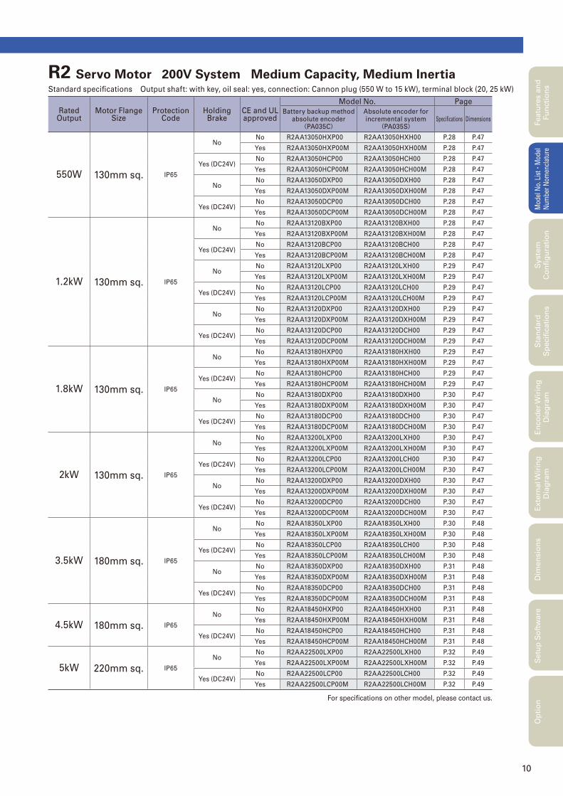
For specifi cations on other model, please contact us.
R2 Servo Motor 200V System Medium Capacity, Medium Inertia Standard specifi cations Output shaft: with key, oil seal: yes, connection: Cannon plug (550 W to 15 kW), terminal block (20, 25 kW)
Rated Output
Motor Flange Size
Protection Code
Holding Brake
CE and ULapproved
Model No. Page
Battery backup methodabsolute encoder(PA035C)
Absolute encoder forincremental system
(PA035S)Specifi cations Dimensions
550W 130mm sq. IP65
NoNo R2AA13050HXP00 R2AA13050HXH00 P.28 P.47
Yes R2AA13050HXP00M R2AA13050HXH00M P.28 P.47
Yes (DC24V)No R2AA13050HCP00 R2AA13050HCH00 P.28 P.47
Yes R2AA13050HCP00M R2AA13050HCH00M P.28 P.47
NoNo R2AA13050DXP00 R2AA13050DXH00 P.28 P.47
Yes R2AA13050DXP00M R2AA13050DXH00M P.28 P.47
Yes (DC24V)No R2AA13050DCP00 R2AA13050DCH00 P.28 P.47
Yes R2AA13050DCP00M R2AA13050DCH00M P.28 P.47
1.2kW 130mm sq. IP65
NoNo R2AA13120BXP00 R2AA13120BXH00 P.28 P.47
Yes R2AA13120BXP00M R2AA13120BXH00M P.28 P.47
Yes (DC24V)No R2AA13120BCP00 R2AA13120BCH00 P.28 P.47
Yes R2AA13120BCP00M R2AA13120BCH00M P.28 P.47
NoNo R2AA13120LXP00 R2AA13120LXH00 P.29 P.47
Yes R2AA13120LXP00M R2AA13120LXH00M P.29 P.47
Yes (DC24V)No R2AA13120LCP00 R2AA13120LCH00 P.29 P.47
Yes R2AA13120LCP00M R2AA13120LCH00M P.29 P.47
NoNo R2AA13120DXP00 R2AA13120DXH00 P.29 P.47
Yes R2AA13120DXP00M R2AA13120DXH00M P.29 P.47
Yes (DC24V)No R2AA13120DCP00 R2AA13120DCH00 P.29 P.47
Yes R2AA13120DCP00M R2AA13120DCH00M P.29 P.47
1.8kW 130mm sq. IP65
NoNo R2AA13180HXP00 R2AA13180HXH00 P.29 P.47
Yes R2AA13180HXP00M R2AA13180HXH00M P.29 P.47
Yes (DC24V)No R2AA13180HCP00 R2AA13180HCH00 P.29 P.47
Yes R2AA13180HCP00M R2AA13180HCH00M P.29 P.47
NoNo R2AA13180DXP00 R2AA13180DXH00 P.30 P.47
Yes R2AA13180DXP00M R2AA13180DXH00M P.30 P.47
Yes (DC24V)No R2AA13180DCP00 R2AA13180DCH00 P.30 P.47
Yes R2AA13180DCP00M R2AA13180DCH00M P.30 P.47
2kW 130mm sq. IP65
NoNo R2AA13200LXP00 R2AA13200LXH00 P.30 P.47
Yes R2AA13200LXP00M R2AA13200LXH00M P.30 P.47
Yes (DC24V)No R2AA13200LCP00 R2AA13200LCH00 P.30 P.47
Yes R2AA13200LCP00M R2AA13200LCH00M P.30 P.47
NoNo R2AA13200DXP00 R2AA13200DXH00 P.30 P.47
Yes R2AA13200DXP00M R2AA13200DXH00M P.30 P.47
Yes (DC24V)No R2AA13200DCP00 R2AA13200DCH00 P.30 P.47
Yes R2AA13200DCP00M R2AA13200DCH00M P.30 P.47
3.5kW 180mm sq. IP65
NoNo R2AA18350LXP00 R2AA18350LXH00 P.30 P.48
Yes R2AA18350LXP00M R2AA18350LXH00M P.30 P.48
Yes (DC24V)No R2AA18350LCP00 R2AA18350LCH00 P.30 P.48
Yes R2AA18350LCP00M R2AA18350LCH00M P.30 P.48
NoNo R2AA18350DXP00 R2AA18350DXH00 P.31 P.48
Yes R2AA18350DXP00M R2AA18350DXH00M P.31 P.48
Yes (DC24V)No R2AA18350DCP00 R2AA18350DCH00 P.31 P.48
Yes R2AA18350DCP00M R2AA18350DCH00M P.31 P.48
4.5kW 180mm sq. IP65
NoNo R2AA18450HXP00 R2AA18450HXH00 P.31 P.48
Yes R2AA18450HXP00M R2AA18450HXH00M P.31 P.48
Yes (DC24V)No R2AA18450HCP00 R2AA18450HCH00 P.31 P.48
Yes R2AA18450HCP00M R2AA18450HCH00M P.31 P.48
5kW 220mm sq. IP65
NoNo R2AA22500LXP00 R2AA22500LXH00 P.32 P.49
Yes R2AA22500LXP00M R2AA22500LXH00M P.32 P.49
Yes (DC24V)No R2AA22500LCP00 R2AA22500LCH00 P.32 P.49
Yes R2AA22500LCP00M R2AA22500LCH00M P.32 P.49
11
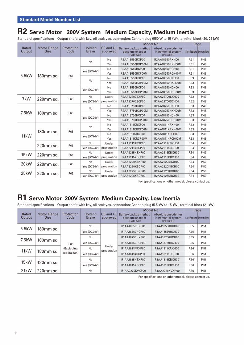
For specifi cations on other model, please contact us.
For specifi cations on other model, please contact us.
Standard Model Number List
R1 Servo Motor 200V System Medium Capacity, Low Inertia Standard specifi cations Output shaft: with key, oil seal: yes, connection: Cannon plug (5.5 kW to 15 kW), terminal block (21 kW)
Rated Output
Motor Flange Size
Protection Code
Holding Brake
CE and ULapproved
Model No. Page
Battery backup methodabsolute encoder(PA035C)
Absolute encoder forincremental system
(PA035S)Specifi cations Dimensions
5.5kW 180mm sq.
IP65
(Excluding
cooling fan)
No
Under
preparation
R1AA18550HXP00 R1AA18550HXH00 P.35 P.51
Yes (DC24V) R1AA18550HCP00 R1AA18550HCH00 P.35 P.51
7.5kW 180mm sq.No R1AA18750HXP00 R1AA18750HXH00 P.35 P.51
Yes (DC24V) R1AA18750HCP00 R1AA18750HCH00 P.35 P.51
11kW 180mm sq.No R1AA1811KRXP00 R1AA1811KRXH00 P.36 P.51
Yes (DC24V) R1AA1811KRCP00 R1AA1811KRCH00 P.36 P.51
15kW 180mm sq.No R1AA1815KBXP00 R1AA1815KBXH00 P.36 P.51
Yes (DC24V) R1AA1815KBCP00 R1AA1815KBCH00 P.36 P.51
21kW 220mm sq. No R1AA2220KVXP00 R1AA2220KVXH00 P.36 P.51
Rated Output
Motor Flange Size
Protection Code
Holding Brake
CE and ULapproved
Model No. Page
Battery backup methodabsolute encoder(PA035C)
Absolute encoder forincremental system
(PA035S)Specifi cations Dimensions
5.5kW 180mm sq. IP65
NoNo R2AA18550RXP00 R2AA18550RXH00 P.31 P.48
Yes R2AA18550RXP00M R2AA18550RXH00M P.31 P.48
Yes (DC24V)No R2AA18550RCP00 R2AA18550RCH00 P.31 P.48
Yes R2AA18550RCP00M R2AA18550RCH00M P.31 P.48
NoNo R2AA18550HXP00 R2AA18550HXH00 P.33 P.48
Yes R2AA18550HXP00M R2AA18550HXH00M P.33 P.48
Yes (DC24V)No R2AA18550HCP00 R2AA18550HCH00 P.33 P.48
Yes R2AA18550HCP00M R2AA18550HCH00M P.33 P.48
7kW 220mm sq. IP65No Under
preparation
R2AA22700SXP00 R2AA22700SXH00 P.32 P.49
Yes (DC24V) R2AA22700SCP00 R2AA22700SCH00 P.32 P.49
7.5kW 180mm sq. IP65
NoNo R2AA18750HXP00 R2AA18750HXH00 P.33 P.48
Yes R2AA18750HXP00M R2AA18750HXH00M P.33 P.48
Yes (DC24V)No R2AA18750HCP00 R2AA18750HCH00 P.33 P.48
Yes R2AA18750HCP00M R2AA18750HCH00M P.33 P.48
11kW180mm sq. IP65
NoNo R2AA1811KRXP00 R2AA1811KRXH00 P.33 P.48
Yes R2AA1811KRXP00M R2AA1811KRXH00M P.33 P.48
Yes (DC24V)No R2AA1811KRCP00 R2AA1811KRCH00 P.33 P.48
Yes R2AA1811KRCP00M R2AA1811KRCH00M P.33 P.48
220mm sq. IP65No Under
preparation
R2AA2211KBXP00 R2AA2211KBXH00 P.34 P.49
Yes (DC24V) R2AA2211KBCP00 R2AA2211KBCH00 P.34 P.49
15kW 220mm sq. IP65No Under
preparation
R2AA2215KBXP00 R2AA2215KBXH00 P.34 P.49
Yes (DC24V) R2AA2215KBCP00 R2AA2215KBCH00 P.34 P.49
20kW 220mm sq. IP65No Under
preparation
R2AA2220KBXP00 R2AA2220KBXH00 P.34 P.50
Yes (DC24V) R2AA2220KBCP00 R2AA2220KBCH00 P.34 P.50
25kW 220mm sq. IP65No Under
preparation
R2AA2225KBXP00 R2AA2225KBXH00 P.34 P.50
Yes (DC24V) R2AA2225KBCP00 R2AA2225KBCH00 P.34 P.50
R2 Servo Motor 200V System Medium Capacity, Medium Inertia Standard specifi cations Output shaft: with key, oil seal: yes, connection: Cannon plug (550 W to 15 kW), terminal block (20, 25 kW)
12
Featu
res a
nd
Fu
ncti
on
sM
odel
No.
Lis
t
・Mod
el
Num
ber
Nom
encl
atur
eS
tan
dard
S
peci�
cati
on
sE
nco
der
Wir
ing
D
iag
ram
Exte
rnal W
irin
g
Dia
gra
mD
imen
sio
ns
Setu
p S
oft
ware
Op
tio
nS
yste
m
Co
n�
gu
rati
on
For speci� cations on other model, please contact us.
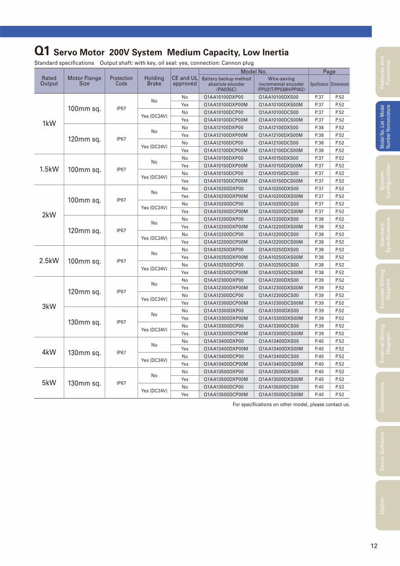
Q1 Servo Motor 200V System Medium Capacity, Low Inertia Standard speci� cations Output shaft: with key, oil seal: yes, connection: Cannon plug
Rated Output
Motor Flange Size
Protection Code
Holding Brake
CE and ULapproved
Model No. Page
Battery backup methodabsolute encoder(PA035C)
Wire-savingincremental encoder(PP031T/PP038H/PP062)
Speci� cations Dimensions
1kW
100mm sq. IP67
NoNo Q1AA10100DXP00 Q1AA10100DXS00 P.37 P.52
Yes Q1AA10100DXP00M Q1AA10100DXS00M P.37 P.52
Yes (DC24V)No Q1AA10100DCP00 Q1AA10100DCS00 P.37 P.52
Yes Q1AA10100DCP00M Q1AA10100DCS00M P.37 P.52
120mm sq. IP67
NoNo Q1AA12100DXP00 Q1AA12100DXS00 P.38 P.52
Yes Q1AA12100DXP00M Q1AA12100DXS00M P.38 P.52
Yes (DC24V)No Q1AA12100DCP00 Q1AA12100DCS00 P.38 P.52
Yes Q1AA12100DCP00M Q1AA12100DCS00M P.38 P.52
1.5kW 100mm sq. IP67
NoNo Q1AA10150DXP00 Q1AA10150DXS00 P.37 P.52
Yes Q1AA10150DXP00M Q1AA10150DXS00M P.37 P.52
Yes (DC24V)No Q1AA10150DCP00 Q1AA10150DCS00 P.37 P.52
Yes Q1AA10150DCP00M Q1AA10150DCS00M P.37 P.52
2kW
100mm sq. IP67
NoNo Q1AA10200DXP00 Q1AA10200DXS00 P.37 P.52
Yes Q1AA10200DXP00M Q1AA10200DXS00M P.37 P.52
Yes (DC24V)No Q1AA10200DCP00 Q1AA10200DCS00 P.37 P.52
Yes Q1AA10200DCP00M Q1AA10200DCS00M P.37 P.52
120mm sq. IP67
NoNo Q1AA12200DXP00 Q1AA12200DXS00 P.38 P.52
Yes Q1AA12200DXP00M Q1AA12200DXS00M P.38 P.52
Yes (DC24V)No Q1AA12200DCP00 Q1AA12200DCS00 P.38 P.52
Yes Q1AA12200DCP00M Q1AA12200DCS00M P.38 P.52
2.5kW 100mm sq. IP67
NoNo Q1AA10250DXP00 Q1AA10250DXS00 P.38 P.52
Yes Q1AA10250DXP00M Q1AA10250DXS00M P.38 P.52
Yes (DC24V)No Q1AA10250DCP00 Q1AA10250DCS00 P.38 P.52
Yes Q1AA10250DCP00M Q1AA10250DCS00M P.38 P.52
3kW
120mm sq. IP67
NoNo Q1AA12300DXP00 Q1AA12300DXS00 P.39 P.52
Yes Q1AA12300DXP00M Q1AA12300DXS00M P.39 P.52
Yes (DC24V)No Q1AA12300DCP00 Q1AA12300DCS00 P.39 P.52
Yes Q1AA12300DCP00 Q1AA12300DCS00 P.39 P.52
130mm sq. IP67
NoNo Q1AA13300DXP00 Q1AA13300DXS00 P.39 P.52
Yes Q1AA13300DXP00M Q1AA13300DXS00M P.39 P.52
Yes (DC24V)No Q1AA13300DCP00 Q1AA13300DCS00 P.39 P.52
Yes Q1AA13300DCP00M Q1AA13300DCS00M P.39 P.52
4kW 130mm sq. IP67
NoNo Q1AA13400DXP00 Q1AA13400DXS00 P.40 P.52
Yes Q1AA13400DXP00M Q1AA13400DXS00M P.40 P.52
Yes (DC24V)No Q1AA13400DCP00 Q1AA13400DCS00 P.40 P.52
Yes Q1AA13400DCP00M Q1AA13400DCS00M P.40 P.52
5kW 130mm sq. IP67
NoNo Q1AA13500DXP00 Q1AA13500DXS00 P.40 P.52
Yes Q1AA13500DXP00M Q1AA13500DXS00M P.40 P.52
Yes (DC24V)No Q1AA13500DCP00 Q1AA13500DCS00 P.40 P.52
Yes Q1AA13500DCP00M Q1AA13500DCS00M P.40 P.52
55
This software allows you to set servo system parameters from a PC. It also allows you
easily to start up or test run the servo system. The software can be downloaded from
Production Information on our website. URL : http://www.sanyodenki.co.jp
Start-up Screen
Main Screen
Alarm Record Display
Current and past alarm occurrence can be checked.
Con� guration parameters
Enables parameter loading, saving, etc., via PC connection
Setup Software Title:R ADVANCED MODEL-Setup Software
Main Functions
Servo ampli� er parameter setting
Servo ampli� er status display
Alarm display and reset
Test run execution
Auto-tuning of vibration control frequency, etc.
Analog command offset adjustment
※ Use the optional PC connection cable (model No.: AL-00689703-01) to
connect the servo ampli� er and the RS-232C port on the PC.
Supported OS
Windows 98/SE/Me/2000/XP/Vista/7
※See our website for details of supported versions.
Monitor Display
Observe Operation and Input/Output signal status
Setup Software
M M
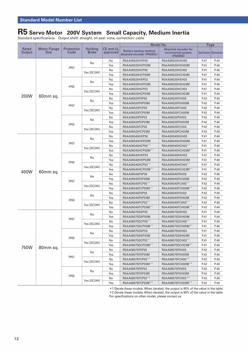
13
Standard Model Number List
*1 Derate these models. When derated, the output is 95% of the value in the table.*2 Derate these models. When derated, the output is 90% of the value in the table.
For specifi cations on other model, please contact us.
Rated Output
Motor Flange Size
Protection Code
Holding Brake
CE and ULapproved
Model No. Page
Battery backup methodabsolute encoder(PA035C)
Absolute encoder forincremental system
(PA035S)Specifi cations Dimensions
200W 60mm sq.
IP67
NoNo R5AA06020HXP00 R5AA06020HXH00 P.41 P.46
Yes R5AA06020HXP00M R5AA06020HXH00M P.41 P.46
Yes (DC24V)No R5AA06020HCP00 R5AA06020HCH00 P.41 P.46
Yes R5AA06020HCP00M R5AA06020HCH00M P.41 P.46
IP65
NoNo R5AA06020HXP03 R5AA06020HXH03 P.41 P.46
Yes R5AA06020HXP03M R5AA06020HXH03M P.41 P.46
Yes (DC24V)No R5AA06020HCP03 R5AA06020HCH03 P.41 P.46
Yes R5AA06020HCP03M R5AA06020HCH03M P.41 P.46
IP67
NoNo R5AA06020FXP00 R5AA06020FXH00 P.42 P.46
Yes R5AA06020FXP00M R5AA06020FXH00M P.42 P.46
Yes (DC24V)No R5AA06020FCP00 R5AA06020FCH00 P.42 P.46
Yes R5AA06020FCP00M R5AA06020FCH00M P.42 P.46
IP65
NoNo R5AA06020FXP03 R5AA06020FXH03 P.42 P.46
Yes R5AA06020FXP03M R5AA06020FXH03M P.42 P.46
Yes (DC24V)No R5AA06020FCP03 R5AA06020FCH03 P.42 P.46
Yes R5AA06020FCP03M R5AA06020FCH03M P.42 P.46
400W 60mm sq.
IP67
NoNo R5AA06040HXP00 R5AA06040HXH00 P.41 P.46
Yes R5AA06040HXP00M R5AA06040HXH00M P.41 P.46
Yes (DC24V)No R5AA06040HCP00*1 R5AA06040HCH00*1 P.41 P.46
Yes R5AA06040HCP00M*1 R5AA06040HCH00M*1 P.41 P.46
IP65
NoNo R5AA06040HXP03 R5AA06040HXH03 P.41 P.46
Yes R5AA06040HXP03M R5AA06040HXH03M P.41 P.46
Yes (DC24V)No R5AA06040HCP03*1 R5AA06040HCH03*1 P.41 P.46
Yes R5AA06040HCP03M*1 R5AA06040HCH03M*1 P.41 P.46
IP67
NoNo R5AA06040FXP00 R5AA06040FXH00 P.42 P.46
Yes R5AA06040FXP00M R5AA06040FXH00M P.42 P.46
Yes (DC24V)No R5AA06040FCP00*1 R5AA06040FCH00*1 P.42 P.46
Yes R5AA06040FCP00M*1 R5AA06040FCH00M*1 P.42 P.46
IP65
NoNo R5AA06040FXP03 R5AA06040FXH03 P.42 P.46
Yes R5AA06040FXP03M R5AA06040FXH03M P.42 P.46
Yes (DC24V)No R5AA06040FCP03*1 R5AA06040FCH03*1 P.42 P.46
Yes R5AA06040FCP03M*1 R5AA06040FCH03M*1 P.42 P.46
750W 80mm sq.
IP67
NoNo R5AA08075DXP00 R5AA08075DXH00 P.41 P.46
Yes R5AA08075DXP00M R5AA08075DXH00M P.41 P.46
Yes (DC24V)No R5AA08075DCP00*1 R5AA08075DCH00*1 P.41 P.46
Yes R5AA08075DCP00M*1 R5AA08075DCH00M*1 P.41 P.46
IP65
NoNo R5AA08075DXP03 R5AA08075DXH03 P.41 P.46
Yes R5AA08075DXP03M R5AA08075DXH03M P.41 P.46
Yes (DC24V)No R5AA08075DCP03*1 R5AA08075DCH03*1 P.41 P.46
Yes R5AA08075DCP03M*1 R5AA08075DCH03M*1 P.41 P.46
IP67
NoNo R5AA08075FXP00 R5AA08075FXH00 P.42 P.46
Yes R5AA08075FXP00M R5AA08075FXH00M P.42 P.46
Yes (DC24V)No R5AA08075FCP00* 2 R5AA08075FCH00* 2 P.42 P.46
Yes R5AA08075FCP00M* 2 R5AA08075FCH00M* 2 P.42 P.46
IP65
NoNo R5AA08075FXP03 R5AA08075FXH03 P.42 P.46
Yes R5AA08075FXP03M R5AA08075FXH03M P.42 P.46
Yes (DC24V)No R5AA08075FCP03* 2 R5AA08075FCH03* 2 P.42 P.46
Yes R5AA08075FCP03M* 2 R5AA08075FCH03M* 2 P.42 P.46
R5 Servo Motor 200V System Small Capacity, Medium Inertia Standard specifi cations Output shaft: straight, oil seal: none, connection: cable
14
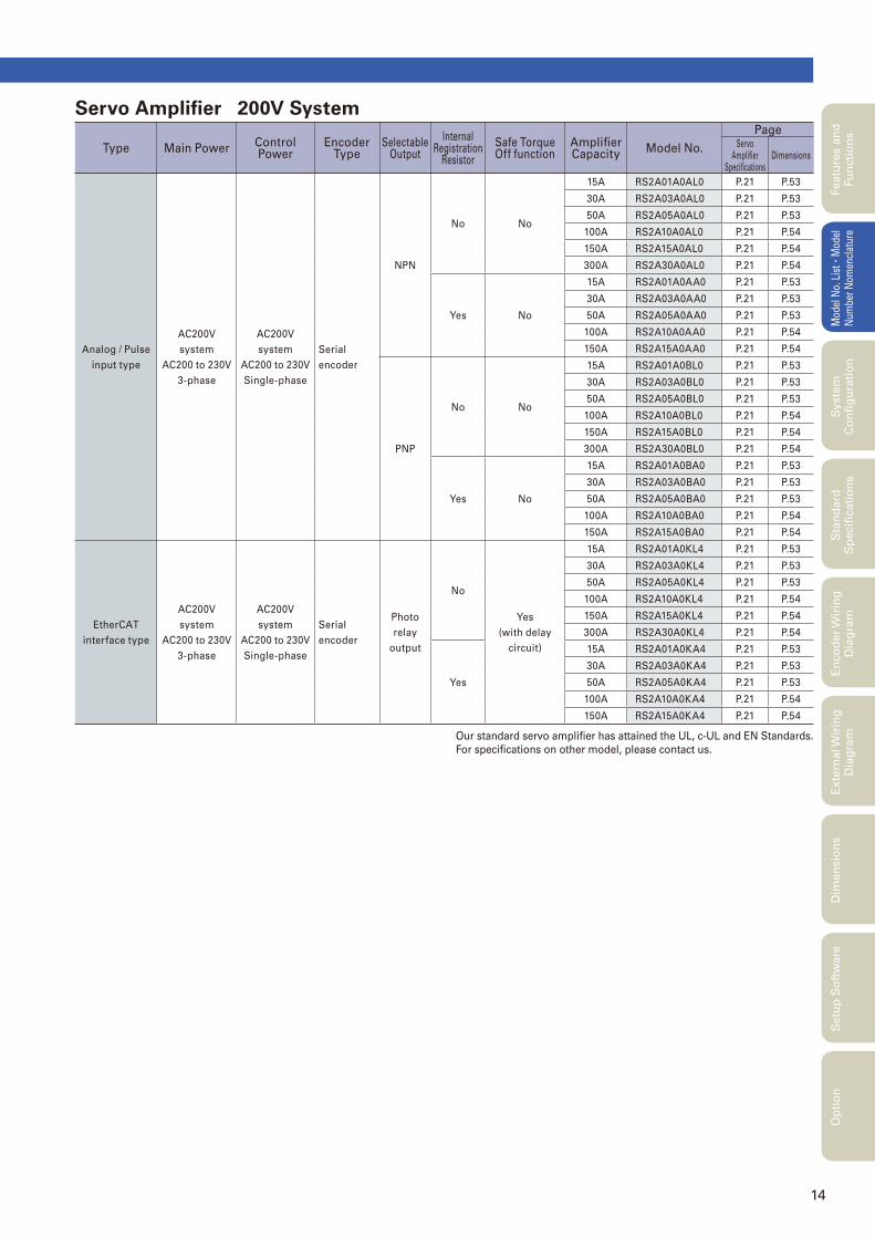
Servo Amplifi er 200V System
Type Main PowerControl Power
Encoder Type
Selectable Output
Internal Registration
Resistor
Safe Torque Off function
Amplifi er Capacity
Model No.
PageServo
Amplifi er Specifi cations
Dimensions
Analog / Pulse
input type
AC200V
system
AC200 to 230V
3-phase
AC200V
system
AC200 to 230V
Single-phase
Serial
encoder
NPN
No No
15A RS2A01A0AL0 P.21 P.53
30A RS2A03A0AL0 P.21 P.53
50A RS2A05A0AL0 P.21 P.53
100A RS2A10A0AL0 P.21 P.54
150A RS2A15A0AL0 P.21 P.54
300A RS2A30A0AL0 P.21 P.54
Yes No
15A RS2A01A0AA0 P.21 P.53
30A RS2A03A0AA0 P.21 P.53
50A RS2A05A0AA0 P.21 P.53
100A RS2A10A0AA0 P.21 P.54
150A RS2A15A0AA0 P.21 P.54
PNP
No No
15A RS2A01A0BL0 P.21 P.53
30A RS2A03A0BL0 P.21 P.53
50A RS2A05A0BL0 P.21 P.53
100A RS2A10A0BL0 P.21 P.54
150A RS2A15A0BL0 P.21 P.54
300A RS2A30A0BL0 P.21 P.54
Yes No
15A RS2A01A0BA0 P.21 P.53
30A RS2A03A0BA0 P.21 P.53
50A RS2A05A0BA0 P.21 P.53
100A RS2A10A0BA0 P.21 P.54
150A RS2A15A0BA0 P.21 P.54
EtherCAT
interface type
AC200V
system
AC200 to 230V
3-phase
AC200V
system
AC200 to 230V
Single-phase
Serial
encoder
Photo
relay
output
No
Yes
(with delay
circuit)
15A RS2A01A0KL4 P.21 P.53
30A RS2A03A0KL4 P.21 P.53
50A RS2A05A0KL4 P.21 P.53
100A RS2A10A0KL4 P.21 P.54
150A RS2A15A0KL4 P.21 P.54
300A RS2A30A0KL4 P.21 P.54
Yes
15A RS2A01A0KA4 P.21 P.53
30A RS2A03A0KA4 P.21 P.53
50A RS2A05A0KA4 P.21 P.53
100A RS2A10A0KA4 P.21 P.54
150A RS2A15A0KA4 P.21 P.54
Our standard servo amplifi er has attained the UL, c-UL and EN Standards.
For specifi cations on other model, please contact us.
Featu
res a
nd
Fu
ncti
on
sM
odel
No.
Lis
t
・Mod
el
Num
ber
Nom
encl
atur
eS
tan
dard
S
pecifi
cati
on
sE
nco
der
Wir
ing
D
iag
ram
Exte
rnal W
irin
g
Dia
gra
mD
imen
sio
ns
Setu
p S
oft
ware
Op
tio
nS
yste
m
Co
nfi
gu
rati
on
15
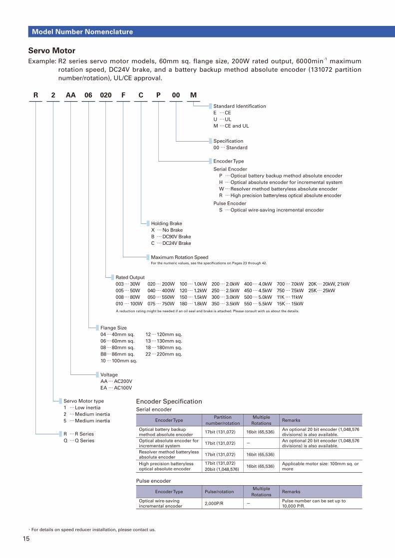
Servo Motor
Example: R2 series servo motor models, 60mm sq. flange size, 200W rated output, 6000min-1 maximum
rotation speed, DC24V brake, and a battery backup method absolute encoder (131072 partition
number/rotation), UL/CE approval.
Model Number Nomenclature
Voltage
AA … AC200V
EA … AC100V
Servo Motor type
1 … Low inertia
2 … Medium inertia
5 … Medium inertia
R … R Series
Q … Q Series
P 00R 2 AA 06 020 F C M
Standard Identification
E … CE
U … UL
M … CE and UL
Specification
00 … Standard
Encoder Type
Serial Encoder
P … Optical battery backup method absolute encoder
H … Optical absolute encoder for incremental system
W … Resolver method batteryless absolute encoder
R … High precision batteryless optical absolute encoder
Pulse Encoder
S … Optical wire-saving incremental encoder
Holding Brake
X … No Brake
B … DC90V Brake
C … DC24V Brake
Maximum Rotation SpeedFor the numeric values, see the specifications on Pages 23 through 42.
Flange Size
04 … 40mm sq.
06 … 60mm sq.
08 … 80mm sq.
B8 … 86mm sq.
10 … 100mm sq.
12 … 120mm sq.
13 … 130mm sq.
18 … 180mm sq.
22 … 220mm sq.
Rated Output
003 … 30W
005 … 50W
008 … 80W
010 … 100W
020 … 200W
040 … 400W
050 … 550W
075 … 750W
100 … 1.0kW
120 … 1.2kW
150 … 1.5kW
180 … 1.8kW
200 … 2.0kW
250 … 2.5kW
300 … 3.0kW
350 … 3.5kW
400 … 4.0kW
450 … 4.5kW
500 … 5.0kW
550 … 5.5kW
700 … 7.0kW
750 … 7.5kW
11K … 11kW
15K … 15kW
20K … 20kW, 21kW
25K … 25kW
A reduction rating might be needed if an oil seal and brake is attached. Please consult with us about the details.
・For details on speed reducer installation, please contact us.
Encoder Specifi cation
Serial encoder
Encoder TypePartition
number/rotation
Multiple
RotationsRemarks
Optical battery backup
method absolute encoder17bit (131,072) 16bit (65,536)
An optional 20 bit encoder (1,048,576
divisions) is also available.
Optical absolute encoder for
incremental system17bit (131,072) - An optional 20 bit encoder (1,048,576
divisions) is also available.
Resolver method batteryless
absolute encoder17bit (131,072) 16bit (65,536)
High precision batteryless
optical absolute encoder
17bit (131,072)
20bit (1,048,576)16bit (65,536)
Applicable motor size: 100mm sq. or
more
Pulse encoder
Encoder Type Pulse/rotationMultiple
RotationsRemarks
Optical wire-saving
incremental encoder2,000P/R - Pulse number can be set up to
10,000 P/R.
16
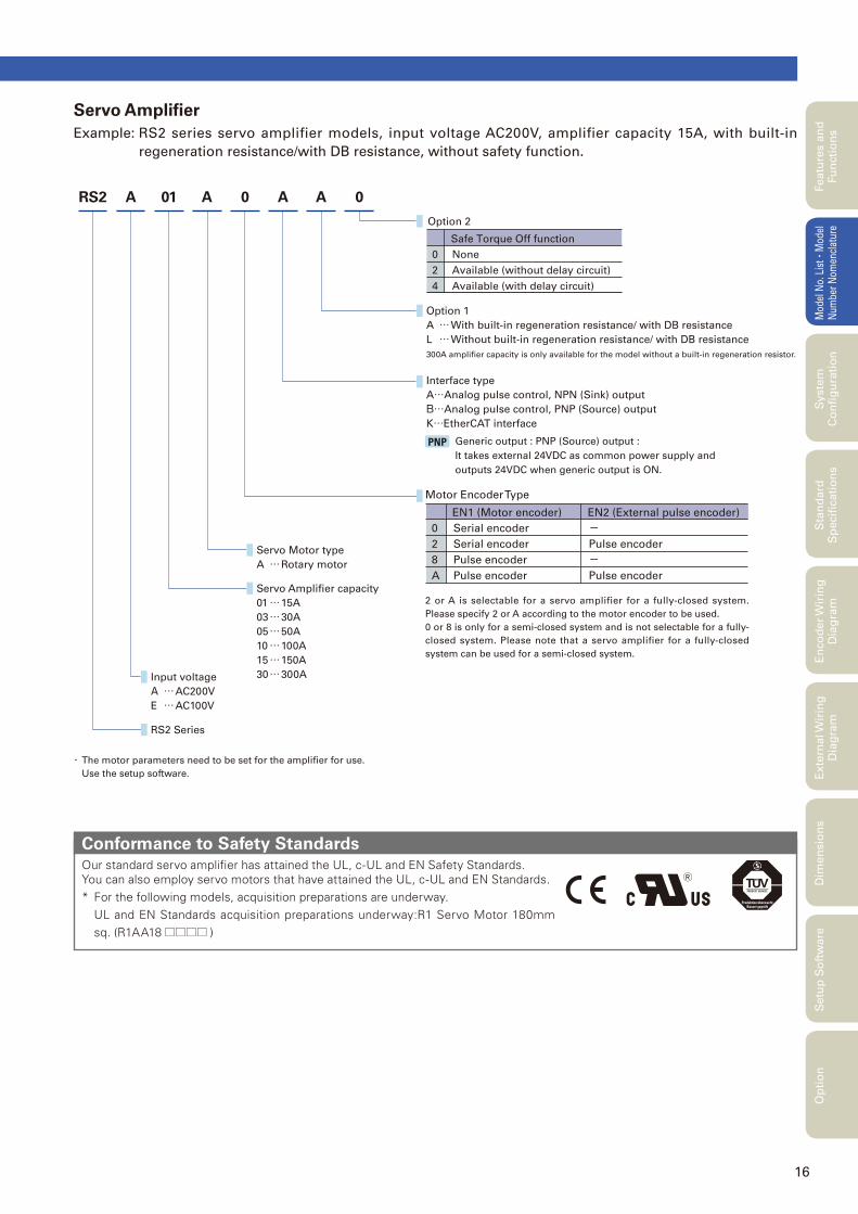
Servo Amplifi er
Example: RS2 series servo amplifier models, input voltage AC200V, amplifier capacity 15A, with built-in
regeneration resistance/with DB resistance, without safety function.
Our standard servo amplifi er has attained the UL, c-UL and EN Safety Standards.You can also employ servo motors that have attained the UL, c-UL and EN Standards.* For the following models, acquisition preparations are underway. UL and EN Standards acquisition preparations underway:R1 Servo Motor 180mm
sq. (R1AA18 □□□□ )
Conformance to Safety Standards
Servo Amplifier capacity
01 … 15A
03 … 30A
05 … 50A
10 … 100A
15 … 150A
30 … 300AInput voltage
A … AC200V
E … AC100V
RS2 Series
0RS2 A 01 A 0 A A
Option 1
A … With built-in regeneration resistance/ with DB resistance
L … Without built-in regeneration resistance/ with DB resistance
300A amplifier capacity is only available for the model without a built-in regeneration resistor.
Interface type
A…Analog pulse control, NPN (Sink) output
B…Analog pulse control, PNP (Source) output
K…EtherCAT interface
Servo Motor type
A … Rotary motor
0
2
4
None
Available (without delay circuit)
Available (with delay circuit)
Safe Torque Off function
Option 2
Generic output : PNP (Source) output :
It takes external 24VDC as common power supply and
outputs 24VDC when generic output is ON.
PNP
0
2
8
A
Serial encoder
Serial encoder
Pulse encoder
Pulse encoder
0
2
8
A
EN1 (Motor encoder)
-Pulse encoder
-Pulse encoder
EN2 (External pulse encoder)
Motor Encoder Type
・ The motor parameters need to be set for the amplifi er for use.
Use the setup software.
2 or A is selectable for a servo amplifier for a fully-closed system.
Please specify 2 or A according to the motor encoder to be used.
0 or 8 is only for a semi-closed system and is not selectable for a fully-
closed system. Please note that a servo amplifier for a fully-closed
system can be used for a semi-closed system.
Featu
res a
nd
Fu
ncti
on
sM
odel
No.
Lis
t
・Mod
el
Num
ber
Nom
encl
atur
eS
tan
dard
S
pecifi
cati
on
sE
nco
der
Wir
ing
D
iag
ram
Exte
rnal W
irin
g
Dia
gra
mD
imen
sio
ns
Setu
p S
oft
ware
Op
tio
nS
yste
m
Co
nfi
gu
rati
on
17
System Configuration
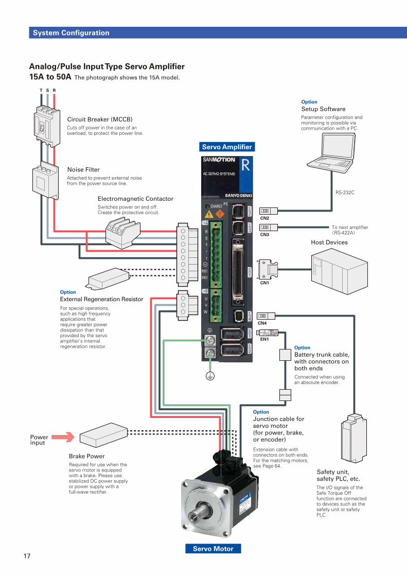
Analog/Pulse Input Type Servo Amplifi er
15A to 50A The photograph shows the 15A model.
Servo Amplifier
Servo Motor
Power input
CN1
EN1
CN3
Cuts off power in the case of an overload, to protect the power line.
Circuit Breaker (MCCB) Parameter configuration and monitoring is possible via communication with a PC.
Setup Software
Host Devices
Attached to prevent external noise from the power source line.
Noise Filter
Switches power on and off.Create the protective circuit.
Electromagnetic Contactor
Required for use when the servo motor is equipped with a brake. Please use stabilized DC power supply or power supply with a full-wave rectifier.
Brake Power
For special operations, such as high frequency applications that require greater power dissipation than that provided by the servo amplifier's internal regeneration resistor.
External Regeneration Resistor
To next amplifier(RS-422A)
RS-232C
CN2
T S R
Option
Extension cable with connectors on both ends.For the matching motors, see Page 64.
Junction cable for servo motor (for power, brake, or encoder)
Option
Connected when using an absolute encoder.
Battery trunk cable, with connectors on both ends
Option
The I/O signals of the Safe Torque Off function are connected to devices such as the safety unit or safety PLC.
Safety unit, safety PLC, etc.
CN4
Option
18
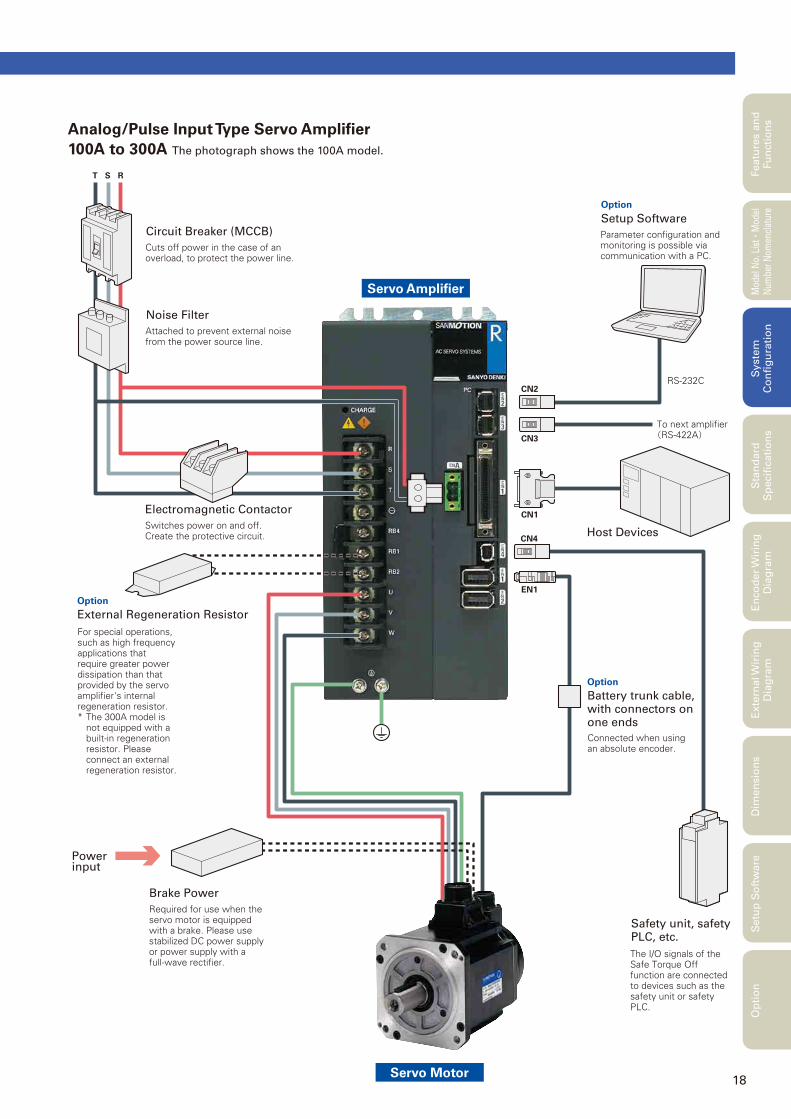
Analog/Pulse Input Type Servo Amplifi er
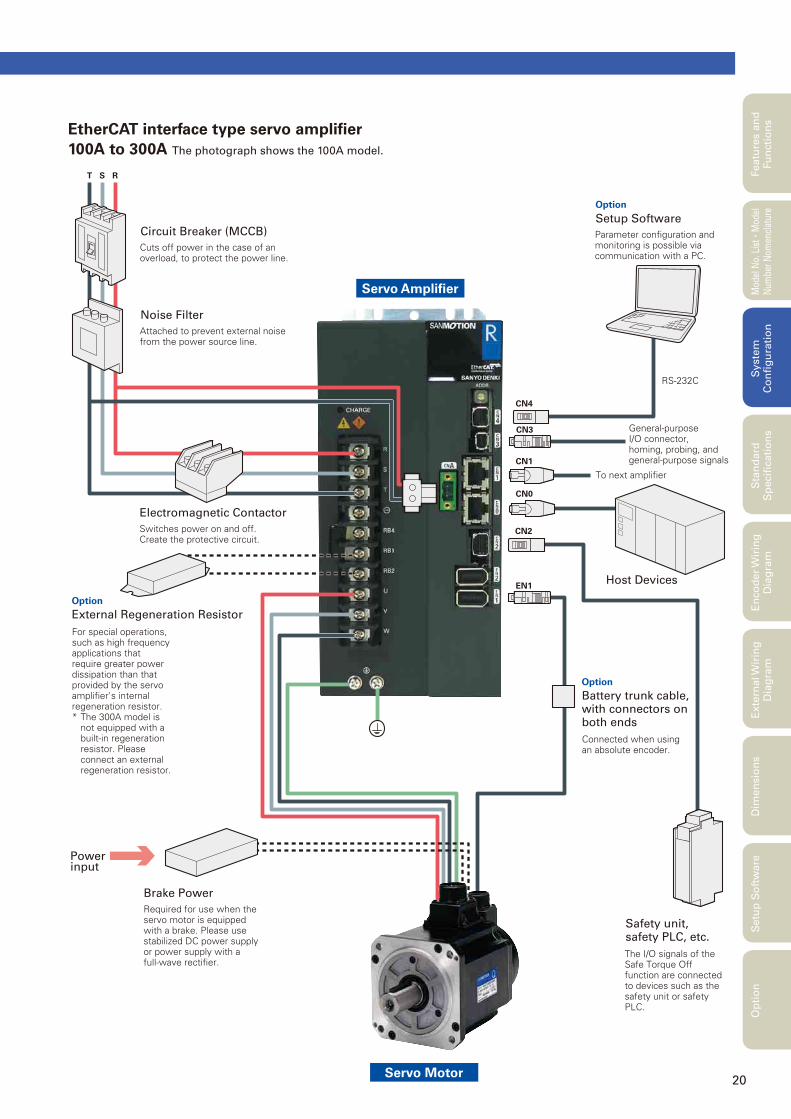
100A to 300A The photograph shows the 100A model.
Featu
res a
nd
Fu
ncti
on
sM
odel
No.
Lis
t
・Mod
el
Num
ber
Nom
encl
atur
eS
tan
dard
S
pecifi
cati
on
sE
nco
der
Wir
ing
D
iag
ram
Exte
rnal W
irin
g
Dia
gra
mD
imen
sio
ns
Setu
p S
oft
ware
Op
tio
nS
yste
m
Co
nfi
gu
rati
on
Servo Amplifier
Servo Motor
Power input
CN1
EN1
CN3
Cuts off power in the case of an overload, to protect the power line.
Circuit Breaker (MCCB) Parameter configuration and monitoring is possible via communication with a PC.
Setup Software
Host Devices
Attached to prevent external noise from the power source line.
Noise Filter
Switches power on and off.Create the protective circuit.
Electromagnetic Contactor
Required for use when the servo motor is equipped with a brake. Please use stabilized DC power supply or power supply with a full-wave rectifier.
Brake Power
For special operations, such as high frequency applications that require greater power dissipation than that provided by the servo amplifier's internal regeneration resistor.* The 300A model is
not equipped with a built-in regeneration resistor. Please connect an external regeneration resistor.
External Regeneration Resistor
To next amplifier(RS-422A)
RS-232CCN2
T S R
Option
Connected when using an absolute encoder.
Battery trunk cable, with connectors on one ends
Option
The I/O signals of the Safe Torque Off function are connected to devices such as the safety unit or safety PLC.
Safety unit, safety PLC, etc.
CN4
Option
19
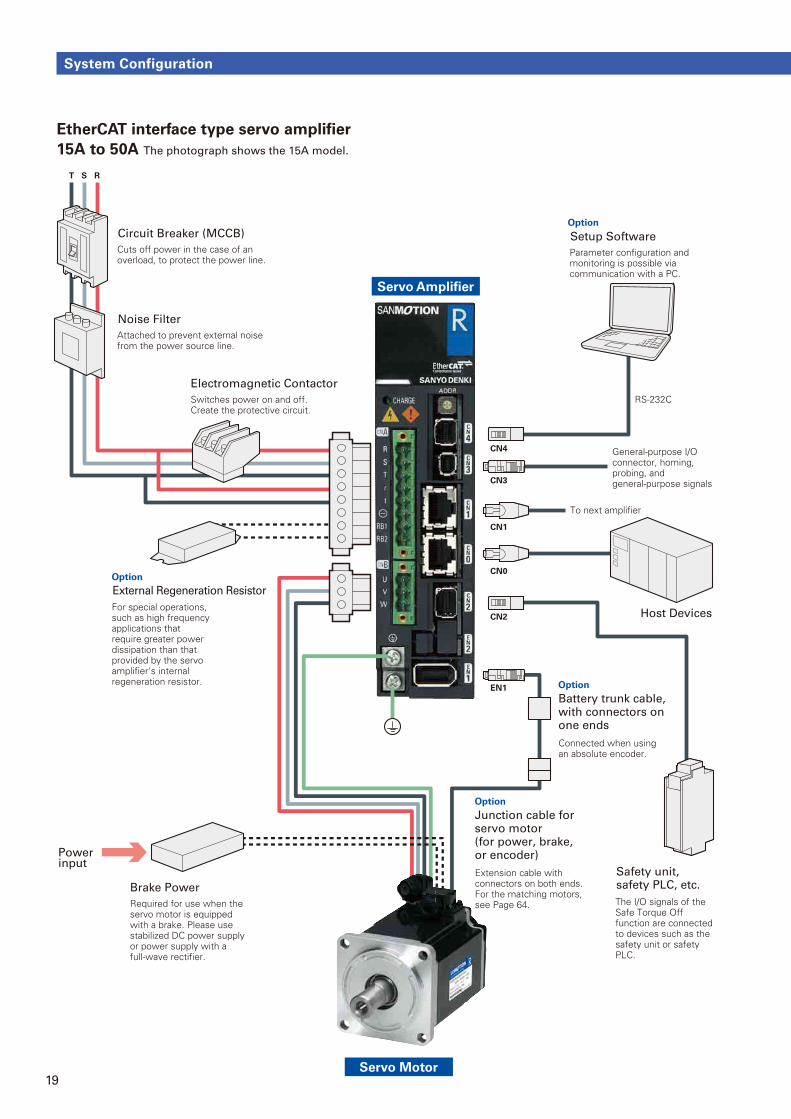
System Configuration
EtherCAT interface type servo amplifi er
15A to 50A The photograph shows the 15A model.
Servo Amplifier
Servo Motor
Power input
CN0
CN1
EN1
CN3
Cuts off power in the case of an overload, to protect the power line.
Circuit Breaker (MCCB)
Parameter configuration and monitoring is possible via communication with a PC.
Setup Software
Attached to prevent external noise from the power source line.
Noise Filter
Switches power on and off.Create the protective circuit.
Electromagnetic Contactor
Required for use when the servo motor is equipped with a brake. Please use stabilized DC power supply or power supply with a full-wave rectifier.
Brake Power
For special operations, such as high frequency applications that require greater power dissipation than that provided by the servo amplifier's internal regeneration resistor.
External Regeneration Resistor
The I/O signals of the Safe Torque Off function are connected to devices such as the safety unit or safety PLC.
Safety unit, safety PLC, etc.
General-purpose I/O connector, homing, probing, and general-purpose signals
To next amplifier
CN2
CN4
T S R
Option
Host Devices
Option
RS-232C
Extension cable with connectors on both ends. For the matching motors, see Page 64.
Junction cable for servo motor (for power, brake, or encoder)
Option
Connected when using an absolute encoder.
Battery trunk cable, with connectors on one ends
Option
20
EtherCAT interface type servo amplifi er
100A to 300A The photograph shows the 100A model.
Featu
res a
nd
Fu
ncti
on
sM
odel
No.
Lis
t
・Mod
el
Num
ber
Nom
encl
atur
eS
tan
dard
S
pecifi
cati
on
sE
nco
der
Wir
ing
D
iag
ram
Exte
rnal W
irin
g
Dia
gra
mD
imen
sio
ns
Setu
p S
oft
ware
Op
tio
nS
yste
m
Co
nfi
gu
rati
on
Servo Amplifier
Servo Motor
Power input
CN0
CN1
CN3 General-purpose I/O connector, homing, probing, and general-purpose signals
To next amplifier
EN1
Cuts off power in the case of an overload, to protect the power line.
Circuit Breaker (MCCB) Parameter configuration and monitoring is possible via communication with a PC.
Setup Software
Host Devices
Attached to prevent external noise from the power source line.
Noise Filter
Switches power on and off.Create the protective circuit.
Electromagnetic Contactor
Required for use when the servo motor is equipped with a brake. Please use stabilized DC power supply or power supply with a full-wave rectifier.
Brake Power
For special operations, such as high frequency applications that require greater power dissipation than that provided by the servo amplifier's internal regeneration resistor.* The 300A model is
not equipped with a built-in regeneration resistor. Please connect an external regeneration resistor.
External Regeneration Resistor
RS-232C
CN4
T S R
Option
Connected when using an absolute encoder.
Battery trunk cable, with connectors on both ends
Option
The I/O signals of the Safe Torque Off function are connected to devices such as the safety unit or safety PLC.
Safety unit, safety PLC, etc.
CN2
Option
21
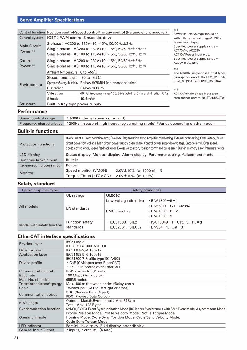
Servo Amplifier Specifications
Performance
Position control/Speed control/Torque control (Parameter changeover)
IGBT:PWM control Sinusoidal drive
Control function
Control system
Main Circuit
Power ※1
Environment
Structure
Control
Power ※1
3-phase:AC200 to 230V+10, -15%, 50/60Hz±3Hz
Single-phase:AC200 to 230V+10, -15%, 50/60Hz±3Hz ※2
Single-phase:AC100 to 115V+10, -15%, 50/60Hz±3Hz ※3
Ambient temperature
Storage temperature
Operation/Storage humidity
Elevation
Vibration
Shock
Built-in tray type power supply
0 to +55℃-20 to +65℃Below 90%RH (no condensation)
Below 1000m
4.9m/s2 Frequency range 10 to 55Hz tested for 2h in each direction X.Y.Z
19.6m/s2
Single-phase:AC200 to 230V+10, -15%, 50/60Hz±3Hz
Single-phase:AC100 to 115V+10, -15%, 50/60Hz±3Hz ※3
※1
Power source voltage should be
within the specified range AC200V
Power input type:
Specified power supply range =
AC170V to AC253V
AC100V Power input type:
Specified power supply range =
AC85V to AC127V
※2
The AC200V single-phase input types
corresponds only to the RS2□01 (15A),
RS2□03 (30A), and RS2□05 (50A).
※3
AC100V single-phase input type
corresponds only to, RS2□01/RS2□03
1:5000 (Internal speed command)
1200Hz (In case of high frequency sampling mode) *Varies depending on the model.
Speed control range
Frequency characteristics
Protection functions
LED display
Dynamic brake circuit
Regeneration process circuit
Monitor
Over current, Current detection error, Overload, Regeneration error, Amplifier overheating, External overheating, Over voltage, Main
circuit power low voltage, Main circuit power supply open phase, Control power supply low voltage, Encoder error, Over speed,
Speed control error, Speed feedback error, Excessive position, Position command pulse error, Built-in memory error, Parameter error
Status display, Monitor display, Alarm display, Parameter setting, Adjustment mode
Built-in
Built-in
Speed monitor (VMON)
Torque (Thrust) (TCMON)
2.0V±10%(at 1000min-1)2.0V±10%(at 100%)
UL ratings
Servo amplifier type Safety standards
UL508C
Low-voltage directive
EMC directive
・IEC61508,SIL2
・IEC62061,SILCL2
・ISO13849-1,Cat.3,PL=d
・EN954-1,Cat.3
・EN61800-5-1
・EN55011 G1 ClassA
・EN61000-6-2
・EN61800-3
EN standardsAll models
Model with safety functionFunction safety
standards
Built-in functions
Safety standard
EtherCAT interface specifi cations
Physical layer
Data link layer
Application layer
Device profile
Communication port
Baud rate
Max. No. of nodes
Transmission distance/topology
Cable
Communication object
PDO length
Synchronization function
Operation mode
LED indicator
General Input/Output
IEC61158-2
IEEE802.3u 100BASE-TX
IEC61158-3,-4 Type12
IEC61158-5,-6 Type12
IEC61800-7 Profile type1(CiA402)
・CoE (CANopen over EtherCAT)
・FoE (File access over EtherCAT)
RJ45 connector (2 ports)
100 Mbps (Full duplex)
65535 nodes
Max. 100 m (between nodes)/Daisy-chain
Twisted-pair CAT5e (straight or cross)
SDO (Service Data Object)
PDO (Process Data Object)
Output:Max.64Byte,Input:Max.64Byte
Total: Max. 128 Bytes
SYNC0, SYNC1 Event Synchronization Mode (DC Mode),Synchronous with SM2 Event Mode, Asynchronous Mode
Profile Position Mode, Profile Velocity Mode, Profile Torque Mode,
Homing Mode, Cycle Sync Position Mode, Cycle Sync Velocity Mode,
Cycle Sync Torque Mode
Port 0/1 link display, RUN display, error display
2 inputs, 2 outputs (4 total)
22
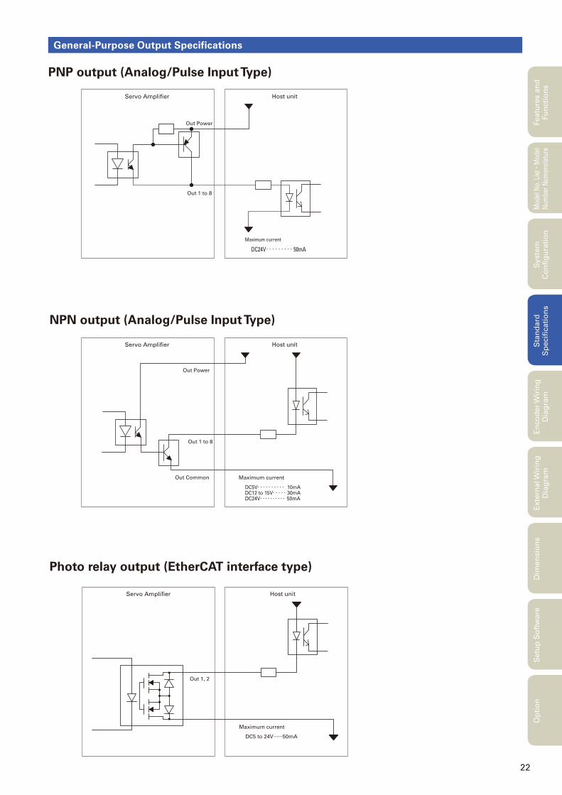
General-Purpose Output Specifications
Servo Amplifier
Out 1, 2
Host unit
Maximum current
DC5 to 24V......50mA
Featu
res a
nd
Fu
ncti
on
sM
odel
No.
Lis
t
・Mod
el
Num
ber
Nom
encl
atur
eS
tan
dard
S
pecifi
cati
on
sE
nco
der
Wir
ing
D
iag
ram
Exte
rnal W
irin
g
Dia
gra
mD
imen
sio
ns
Setu
p S
oft
ware
Op
tio
nS
yste
m
Co
nfi
gu
rati
on
Servo Amplifier Host unit
Out 1 to 8
Out Power
Maximum current
DC24V. . . . . . . . . 50mA
Servo Amplifier
Out Power
Out 1 to 8
Out Common
Host unit
Maximum current
DC5V. . . . . . . . . . 10mADC12 to 15V. . . . . 30mADC24V. . . . . . . . . . 50mA
PNP output (Analog/Pulse Input Type)
NPN output (Analog/Pulse Input Type)
Photo relay output (EtherCAT interface type)
23
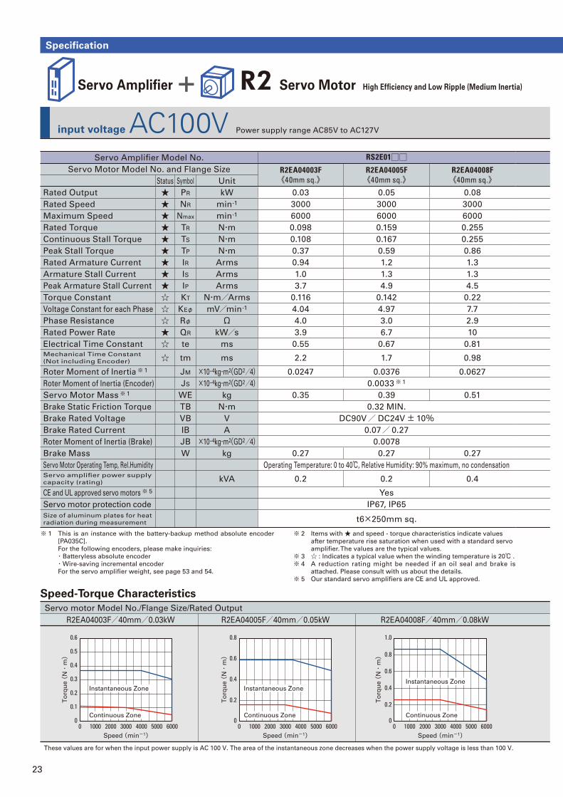
Servo Amplifi er + R2 Servo Motor High Effi ciency and Low Ripple (Medium Inertia)
input voltage AC100V Power supply range AC85V to AC127V
Specification
Servo motor Model No./Flange Size/Rated Output
R2EA04003F/40mm/0.03kW R2EA04005F/40mm/0.05kW R2EA04008F/40mm/0.08kW
0
0.1
0.2
0.3
0.4
0.5
0.6
6000500040003000Speed (min-1)
To
rqu
e (
N・
m)
2000100000
1.0
0.8
0.6
0.4
0.2
6000500040003000Speed (min-1)
To
rqu
e (
N・
m)
2000100000
0.8
0.6
0.4
0.2
6000500040003000Speed (min-1)
To
rqu
e (
N・
m)
200010000
These values are for when the input power supply is AC 100 V. The area of the instantaneous zone decreases when the power supply voltage is less than 100 V.
Instantaneous Zone
Continuous Zone
Instantaneous Zone
Continuous Zone
Instantaneous Zone
Continuous Zone
Servo Amplifi er Model No. RS2E01□□Servo Motor Model No. and Flange Size R2EA04003F
《40mm sq.》R2EA04005F《40mm sq.》
R2EA04008F《40mm sq.》Status Symbol Unit
Rated Output ★ PR kW 0.03 0.05 0.08
Rated Speed ★ NR min-1 3000 3000 3000
Maximum Speed ★ Nmax min-1 6000 6000 6000
Rated Torque ★ TR N・m 0.098 0.159 0.255
Continuous Stall Torque ★ TS N・m 0.108 0.167 0.255
Peak Stall Torque ★ TP N・m 0.37 0.59 0.86
Rated Armature Current ★ IR Arms 0.94 1.2 1.3
Armature Stall Current ★ IS Arms 1.0 1.3 1.3
Peak Armature Stall Current ★ IP Arms 3.7 4.9 4.5
Torque Constant ☆ KT N・m/Arms 0.116 0.142 0.22
Voltage Constant for each Phase ☆ KEφ mV/min-1 4.04 4.97 7.7
Phase Resistance ☆ Rφ Ω 4.0 3.0 2.9
Rated Power Rate ★ QR kW/s 3.9 6.7 10
Electrical Time Constant ☆ te ms 0.55 0.67 0.81Mechanical Time Constant
(Not including Encoder) ☆ tm ms 2.2 1.7 0.98
Roter Moment of Inertia※ 1 JM ×10-4kg・m2(GD2/4) 0.0247 0.0376 0.0627
Roter Moment of Inertia (Encoder) JS ×10-4kg・m2(GD2/4) 0.0033※ 1
Servo Motor Mass※ 1 WE kg 0.35 0.39 0.51
Brake Static Friction Torque TB N・m 0.32 MIN.
Brake Rated Voltage VB V DC90V/ DC24V± 10%Brake Rated Current IB A 0.07/ 0.27
Roter Moment of Inertia (Brake) JB ×10-4kg・m2(GD2/4) 0.0078
Brake Mass W kg 0.27 0.27 0.27
Servo Motor Operating Temp, Rel.Humidity Operating Temperature: 0 to 40℃, Relative Humidity: 90% maximum, no condensationServo amplifi er power supply
capacity (rating) kVA 0.2 0.2 0.4
CE and UL approved servo motors※ 5 Yes
Servo motor protection code IP67, IP65
Size of aluminum plates for heat
radiation during measurement t6×250mm sq.
※ 1 This is an instance with the battery-backup method absolute encoder
[PA035C].
For the following encoders, please make inquiries:
・Batteryless absolute encoder
・Wire-saving incremental encoder
For the servo amplifi er weight, see page 53 and 54.
※ 2 Items with ★ and speed - torque characteristics indicate values
after temperature rise saturation when used with a standard servo
amplifi er. The values are the typical values.
※ 3 ☆ : Indicates a typical value when the winding temperature is 20℃ .
※ 4 A reduction rating might be needed if an oil seal and brake is
attached. Please consult with us about the details.
※ 5 Our standard servo amplifi ers are CE and UL approved.
Speed-Torque Characteristics
24
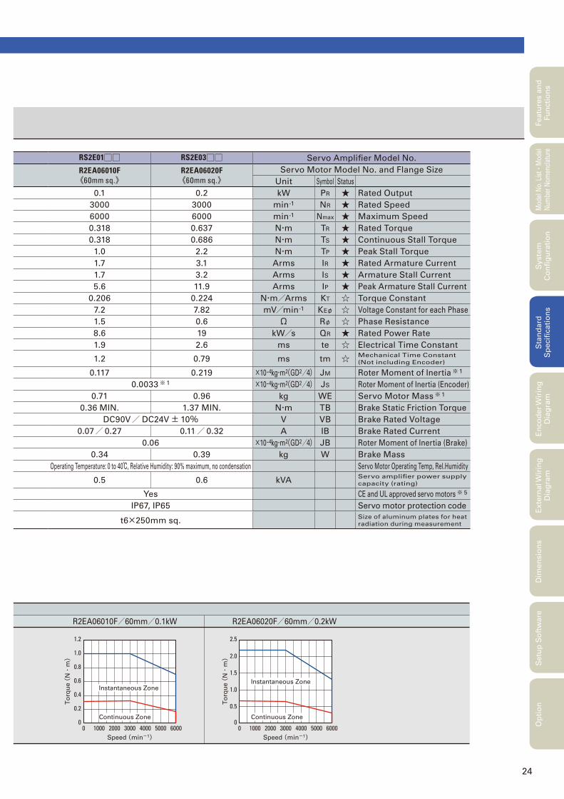
R2EA06010F/60mm/0.1kW R2EA06020F/60mm/0.2kW
0
0.2
0.4
0.6
0.8
1.0
1.2
6000500040003000Speed (min-1)
To
rqu
e (
N・
m)
2000100000
2.5
2.0
1.5
1.0
0.5
6000500040003000Speed (min-1)
To
rqu
e (
N・
m)
200010000
Instantaneous Zone
Continuous Zone
Instantaneous Zone
Continuous Zone
Featu
res a
nd
Fu
ncti
on
sM
odel
No.
Lis
t
・Mod
el
Num
ber
Nom
encl
atur
eS
tan
dard
S
pecifi
cati
on
sE
nco
der
Wir
ing
D
iag
ram
Exte
rnal W
irin
g
Dia
gra
mD
imen
sio
ns
Setu
p S
oft
ware
Op
tio
nS
yste
m
Co
nfi
gu
rati
on
RS2E01□□ RS2E03□□ Servo Amplifi er Model No.
R2EA06010F《60mm sq.》
R2EA06020F《60mm sq.》
Servo Motor Model No. and Flange Size
Unit Symbol Status
0.1 0.2 kW PR ★ Rated Output
3000 3000 min-1 NR ★ Rated Speed
6000 6000 min-1 Nmax ★ Maximum Speed
0.318 0.637 N・m TR ★ Rated Torque
0.318 0.686 N・m TS ★ Continuous Stall Torque
1.0 2.2 N・m TP ★ Peak Stall Torque
1.7 3.1 Arms IR ★ Rated Armature Current
1.7 3.2 Arms IS ★ Armature Stall Current
5.6 11.9 Arms IP ★ Peak Armature Stall Current
0.206 0.224 N・m/Arms KT ☆ Torque Constant
7.2 7.82 mV/min-1 KEφ ☆ Voltage Constant for each Phase
1.5 0.6 Ω Rφ ☆ Phase Resistance
8.6 19 kW/s QR ★ Rated Power Rate
1.9 2.6 ms te ☆ Electrical Time Constant
1.2 0.79 ms tm ☆ Mechanical Time Constant
(Not including Encoder)
0.117 0.219 ×10⁻⁴kg・m2(GD2/4) JM Roter Moment of Inertia※ 1
0.0033※ 1 ×10⁻⁴kg・m2(GD2/4) JS Roter Moment of Inertia (Encoder)
0.71 0.96 kg WE Servo Motor Mass※ 1
0.36 MIN. 1.37 MIN. N・m TB Brake Static Friction Torque
DC90V/ DC24V± 10% V VB Brake Rated Voltage
0.07/ 0.27 0.11/ 0.32 A IB Brake Rated Current
0.06 ×10⁻⁴kg・m2(GD2/4) JB Roter Moment of Inertia (Brake)
0.34 0.39 kg W Brake Mass
Operating Temperature: 0 to 40℃, Relative Humidity: 90% maximum, no condensation Servo Motor Operating Temp, Rel.Humidity
0.5 0.6 kVAServo amplifi er power supply
capacity (rating)
Yes CE and UL approved servo motors※ 5
IP67, IP65 Servo motor protection code
t6×250mm sq.Size of aluminum plates for heat
radiation during measurement
25
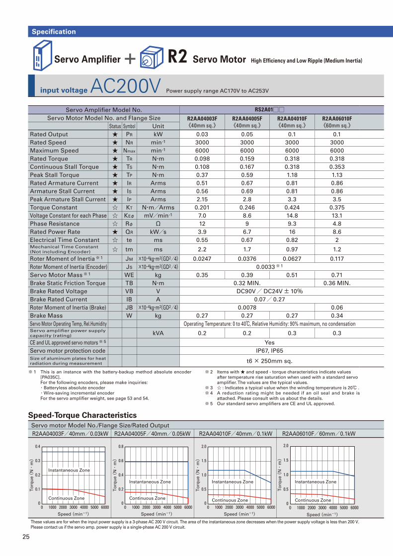
input voltage AC200V Power supply range AC170V to AC253V
Specification
Servo motor Model No./Flange Size/Rated Output
R2AA04003F/40mm/0.03kW R2AA04005F/40mm/0.05kW R2AA04010F/40mm/0.1kW R2AA06010F/60mm/0.1kW
These values are for when the input power supply is a 3-phase AC 200 V circuit. The area of the instantaneous zone decreases when the power supply voltage is less than 200 V.
Please contact us if the servo amp. power supply is a single-phase AC 200 V circuit.
0
2.0
1.5
1.0
0.5
6000500040003000
Speed (min-1)
To
rqu
e (
N・
m)
2000100000
0.8
0.6
0.4
0.2
6000500040003000
Speed (min-1)
To
rqu
e (
N・
m)
2000100000
0.4
0.3
0.2
0.1
6000500040003000
Speed (min-1)
To
rqu
e (
N・
m)
2000100000
2.0
1.5
1.0
0.5
6000500040003000
Speed (min-1)
To
rqu
e (
N・
m)
200010000
Instantaneous Zone
Continuous Zone
Instantaneous Zone
Continuous Zone
Instantaneous Zone
Continuous Zone
Instantaneous Zone
Continuous Zone
Servo Amplifi er + R2 Servo Motor High Effi ciency and Low Ripple (Medium Inertia)
Servo Amplifi er Model No. RS2A01□□Servo Motor Model No. and Flange Size R2AA04003F
《40mm sq.》R2AA04005F《40mm sq.》
R2AA04010F《40mm sq.》
R2AA06010F《60mm sq.》Status Symbol Unit
Rated Output ★ PR kW 0.03 0.05 0.1 0.1
Rated Speed ★ NR min-1 3000 3000 3000 3000
Maximum Speed ★ Nmax min-1 6000 6000 6000 6000
Rated Torque ★ TR N・m 0.098 0.159 0.318 0.318
Continuous Stall Torque ★ TS N・m 0.108 0.167 0.318 0.353
Peak Stall Torque ★ TP N・m 0.37 0.59 1.18 1.13
Rated Armature Current ★ IR Arms 0.51 0.67 0.81 0.86
Armature Stall Current ★ IS Arms 0.56 0.69 0.81 0.86
Peak Armature Stall Current ★ IP Arms 2.15 2.8 3.3 3.5
Torque Constant ☆ KT N・m/Arms 0.201 0.246 0.424 0.375
Voltage Constant for each Phase ☆ KEφ mV/min-1 7.0 8.6 14.8 13.1
Phase Resistance ☆ Rφ Ω 12 9 9.3 4.8
Rated Power Rate ★ QR kW/s 3.9 6.7 16 8.6
Electrical Time Constant ☆ te ms 0.55 0.67 0.82 2Mechanical Time Constant
(Not including Encoder) ☆ tm ms 2.2 1.7 0.97 1.2
Roter Moment of Inertia※ 1 JM ×10-4kg・m2(GD2/4) 0.0247 0.0376 0.0627 0.117
Roter Moment of Inertia (Encoder) JS ×10-4kg・m2(GD2/4) 0.0033※ 1
Servo Motor Mass※ 1 WE kg 0.35 0.39 0.51 0.71
Brake Static Friction Torque TB N・m 0.32 MIN. 0.36 MIN.
Brake Rated Voltage VB V DC90V/ DC24V± 10%Brake Rated Current IB A 0.07/ 0.27
Roter Moment of Inertia (Brake) JB ×10-4kg・m2(GD2/4) 0.0078 0.06
Brake Mass W kg 0.27 0.27 0.27 0.34
Servo Motor Operating Temp, Rel.Humidity Operating Temperature: 0 to 40℃, Relative Humidity: 90% maximum, no condensationServo amplifi er power supply
capacity (rating) kVA 0.2 0.2 0.3 0.3
CE and UL approved servo motors※ 5 Yes
Servo motor protection code IP67, IP65
Size of aluminum plates for heat
radiation during measurement t6 × 250mm sq.
Speed-Torque Characteristics
※ 1 This is an instance with the battery-backup method absolute encoder
[PA035C].
For the following encoders, please make inquiries:
・Batteryless absolute encoder
・Wire-saving incremental encoder
For the servo amplifi er weight, see page 53 and 54.
※ 2 Items with ★ and speed - torque characteristics indicate values
after temperature rise saturation when used with a standard servo
amplifi er. The values are the typical values.
※ 3 ☆ : Indicates a typical value when the winding temperature is 20℃ .
※ 4 A reduction rating might be needed if an oil seal and brake is
attached. Please consult with us about the details.
※ 5 Our standard servo amplifi ers are CE and UL approved.
26
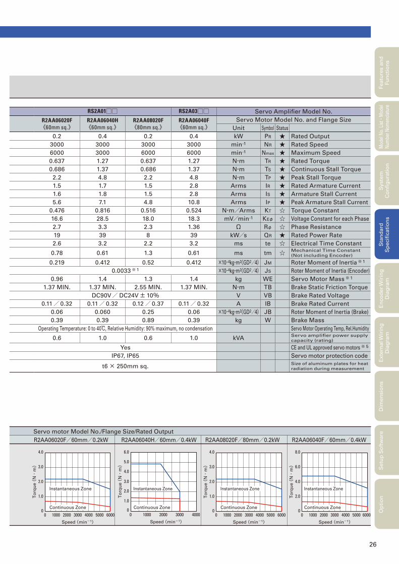
Servo motor Model No./Flange Size/Rated Output
R2AA06020F/60mm/0.2kW R2AA06040H/60mm/0.4kW R2AA08020F/80mm/0.2kW R2AA06040F/60mm/0.4kW
0
4.0
3.0
2.0
1.0
6000500040003000
Speed (min-1)
To
rqu
e (
N・
m)
200010000
Speed (min-1)
To
rqu
e (
N・
m)
0
4.0
3.0
2.0
1.0
6000500040003000
Speed (min-1)
To
rqu
e (
N・
m)
200010000
400020001000 3000
1.0
0
2.0
3.0
4.0
5.0
6.0
00
8.0
6.0
4.0
2.0
5000 600040003000
Speed (min-1)
To
rqu
e (
N・
m)
200010000
Instantaneous Zone
Continuous Zone
Instantaneous Zone
Continuous Zone
Instantaneous Zone
Continuous Zone
Instantaneous Zone
Continuous Zone
Featu
res a
nd
Fu
ncti
on
sM
odel
No.
Lis
t
・Mod
el
Num
ber
Nom
encl
atur
eS
tan
dard
S
pecifi
cati
on
sE
nco
der
Wir
ing
D
iag
ram
Exte
rnal W
irin
g
Dia
gra
mD
imen
sio
ns
Setu
p S
oft
ware
Op
tio
nS
yste
m
Co
nfi
gu
rati
on
RS2A01□□ RS2A03□□ Servo Amplifi er Model No.
R2AA06020F《60mm sq.》
R2AA06040H《60mm sq.》
R2AA08020F《80mm sq.》
R2AA06040F《60mm sq.》
Servo Motor Model No. and Flange Size
Unit Symbol Status
0.2 0.4 0.2 0.4 kW PR ★ Rated Output
3000 3000 3000 3000 min-1 NR ★ Rated Speed
6000 3000 6000 6000 min-1 Nmax ★ Maximum Speed
0.637 1.27 0.637 1.27 N・m TR ★ Rated Torque
0.686 1.37 0.686 1.37 N・m TS ★ Continuous Stall Torque
2.2 4.8 2.2 4.8 N・m TP ★ Peak Stall Torque
1.5 1.7 1.5 2.8 Arms IR ★ Rated Armature Current
1.6 1.8 1.5 2.8 Arms IS ★ Armature Stall Current
5.6 7.1 4.8 10.8 Arms IP ★ Peak Armature Stall Current
0.476 0.816 0.516 0.524 N・m/Arms KT ☆ Torque Constant
16.6 28.5 18.0 18.3 mV/min-1 KEφ ☆ Voltage Constant for each Phase
2.7 3.3 2.3 1.36 Ω Rφ ☆ Phase Resistance
19 39 8 39 kW/s QR ★ Rated Power Rate
2.6 3.2 2.2 3.2 ms te ☆ Electrical Time Constant
0.78 0.61 1.3 0.61 ms tm ☆ Mechanical Time Constant
(Not including Encoder)
0.219 0.412 0.52 0.412 ×10⁻⁴kg・m2(GD2/4) JM Roter Moment of Inertia※ 1
0.0033※ 1 ×10⁻⁴kg・m2(GD2/4) JS Roter Moment of Inertia (Encoder)
0.96 1.4 1.3 1.4 kg WE Servo Motor Mass※ 1
1.37 MIN. 1.37 MIN. 2.55 MIN. 1.37 MIN. N・m TB Brake Static Friction Torque
DC90V/ DC24V± 10% V VB Brake Rated Voltage
0.11/ 0.32 0.11/ 0.32 0.12/ 0.37 0.11/ 0.32 A IB Brake Rated Current
0.06 0.060 0.25 0.06 ×10⁻⁴kg・m2(GD2/4) JB Roter Moment of Inertia (Brake)
0.39 0.39 0.89 0.39 kg W Brake Mass
Operating Temperature: 0 to 40℃, Relative Humidity: 90% maximum, no condensation Servo Motor Operating Temp, Rel.Humidity
0.6 1.0 0.6 1.0 kVAServo amplifi er power supply
capacity (rating)
Yes CE and UL approved servo motors※ 5
IP67, IP65 Servo motor protection code
t6 × 250mm sq.Size of aluminum plates for heat
radiation during measurement

27
input voltage AC200V Power supply range AC170V to AC253V
Specification
Servo motor Model No./Flange Size/Rated Output
R2AA08040F/80mm/0.4kW R2AA08075F/80mm/0.75kW R2AA10075F/100mm/0.75kWR2AAB8100H/86mm/1.0kW
These values are for when the input power supply is a 3-phase AC 200 V circuit. The area of the instantaneous zone decreases when the power supply voltage is less than 200 V.
Please contact us if the servo amp. power supply is a single-phase AC 200 V circuit.
0
8.0
6.0
4.0
2.0
6000500040003000
Speed (min-1)
To
rqu
e (
N・
m)
200010000
0
10
8
6
4
2
6000500040003000
Speed (min-1)
To
rqu
e (
N・
m)
200010000
Speed (min-1)
To
rqu
e (
N・
m)
15000
10
5
0
15
500 1000 30002000 2500 3500
Speed (min-1)
To
rqu
e (
N・
m)
3000
10
10000
2
0
4
6
8
2000 700050004000 6000
Instantaneous Zone
Continuous Zone
Instantaneous Zone
Continuous Zone
Instantaneous Zone
Continuous Zone
Instantaneous Zone
Continuous Zone
Servo Amplifi er + R2 Servo Motor High Effi ciency and Low Ripple (Medium Inertia)
Servo Amplifi er Model No. RS2A03□□Servo Motor Model No. and Flange Size R2AA08040F
《80mm sq.》R2AA08075F《80mm sq.》
R2AAB8100H《86mm sq.》
R2AA10075F《100mm sq.》Status Symbol Unit
Rated Output ★ PR kW 0.4 0.75 1.0 0.75
Rated Speed ★ NR min-1 3000 3000 3000 3000
Maximum Speed ★ Nmax min-1 6000 6000 3000 6000
Rated Torque ★ TR N・m 1.27 2.39 3.18 2.39
Continuous Stall Torque ★ TS N・m 1.37 2.55 3.92 2.55
Peak Stall Torque ★ TP N・m 4.4 8.5 11.6 8.6
Rated Armature Current ★ IR Arms 2.6 4.6 4.6 4.4
Armature Stall Current ★ IS Arms 2.6 4.6 4.7 4.6
Peak Armature Stall Current ★ IP Arms 8.9 15.5 15.5 15.5
Torque Constant ☆ KT N・m/Arms 0.559 0.559 0.825 0.582
Voltage Constant for each Phase ☆ KEφ mV/min-1 19.5 19.5 28.8 20.3
Phase Resistance ☆ Rφ Ω 0.93 0.4 0.85 0.69
Rated Power Rate ★ QR kW/s 16 31 42 29
Electrical Time Constant ☆ te ms 2.5 3 4.6 7.0Mechanical Time Constant
(Not including Encoder) ☆ tm ms 0.93 0.7 0.89 1.2
Roter Moment of Inertia※ 1 JM ×10-4kg・m2(GD2/4) 1.04 1.82 2.38 2.00
Roter Moment of Inertia (Encoder) JS ×10-4kg・m2(GD2/4) 0.0033※ 1
Servo Motor Mass※ 1 WE kg 1.7 2.7 3.6 3.3
Brake Static Friction Torque TB N・m 2.55 MIN. 3.92 MIN.
Brake Rated Voltage VB V DC90V/ DC24V± 10%Brake Rated Current IB A 0.12/ 0.37 0.09/ 0.30
Roter Moment of Inertia (Brake) JB ×10-4kg・m2(GD2/4) 0.25 0.343
Brake Mass W kg 0.89 0.89 0.84 0.9
Servo Motor Operating Temp, Rel.Humidity Operating Temperature: 0 to 40℃, Relative Humidity: 90% maximum, no condensationServo amplifi er power supply
capacity (rating) kVA 1.0 1.6 2.0 1.7
CE and UL approved servo motors※ 5 Yes
Servo motor protection code IP67, IP65
Size of aluminum plates for heat
radiation during measurement t6 × 250mm sq. t12 × 305mm sq.
Speed-Torque Characteristics
※ 1 This is an instance with the battery-backup method absolute encoder
[PA035C].
For the following encoders, please make inquiries:
・Batteryless absolute encoder
・Wire-saving incremental encoder [PP031T]
For the servo amplifi er weight, see page 53 and 54.
※ 2 Items with ★ and speed - torque characteristics indicate values
after temperature rise saturation when used with a standard servo
amplifi er. The values are the typical values.
※ 3 ☆ : Indicates a typical value when the winding temperature is 20℃ .
※ 4 A reduction rating might be needed if an oil seal and brake is
attached. Please consult with us about the details.
※ 5 Our standard servo amplifi ers are CE and UL approved.
28
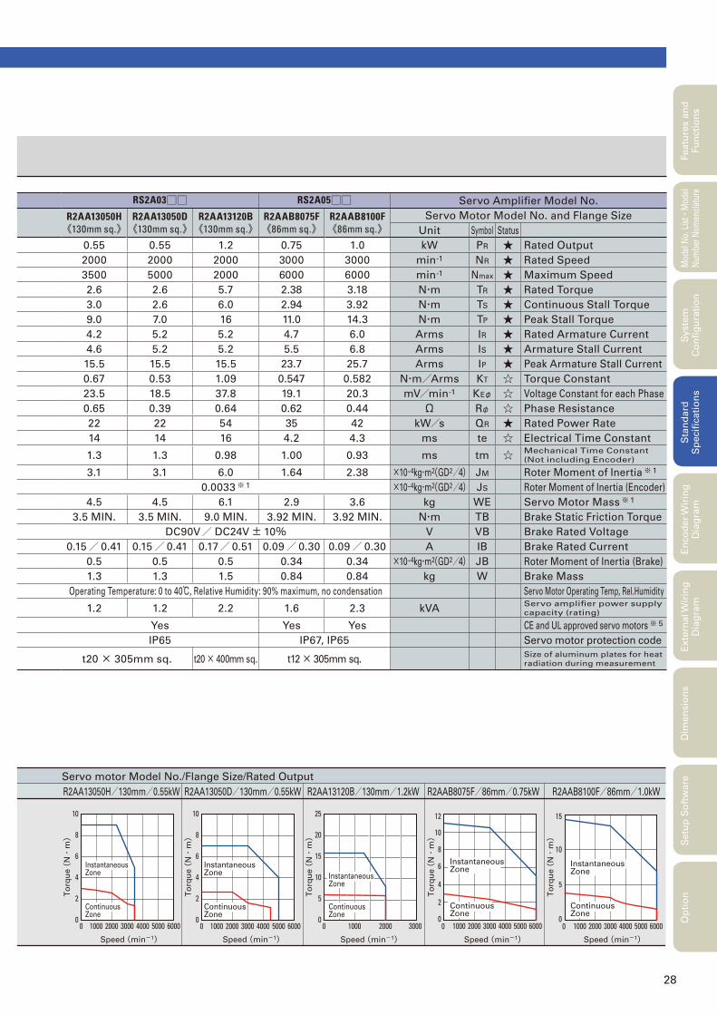
Servo motor Model No./Flange Size/Rated Output
R2AA13050H/130mm/0.55kW R2AA13120B/130mm/1.2kWR2AA13050D/130mm/0.55kW R2AAB8100F/86mm/1.0kWR2AAB8075F/86mm/0.75kW
Speed (min-1)
To
rqu
e (
N・
m)
Speed (min-1)
To
rqu
e (
N・
m)
Speed (min-1)
To
rqu
e (
N・
m)
Speed (min-1)
To
rqu
e (
N・
m)
Speed (min-1)
To
rqu
e (
N・
m)
0 6000500040003000200010000
5
10
15
0 6000500040003000200010000
4
2
8
10
6
1210
8
6
4
2
010000 2000 3000 4000 5000 6000
10
8
6
4
2
010000 2000 3000 4000 5000 6000
25
20
15
10
5
01000 2000 30000
Instantaneous Zone
Continuous Zone
Instantaneous Zone
Continuous Zone
Instantaneous Zone
Continuous Zone
Instantaneous Zone
Continuous Zone
Instantaneous Zone
Continuous Zone
Featu
res a
nd
Fu
ncti
on
sM
odel
No.
Lis
t
・Mod
el
Num
ber
Nom
encl
atur
eS
tan
dard
S
pecifi
cati
on
sE
nco
der
Wir
ing
D
iag
ram
Exte
rnal W
irin
g
Dia
gra
mD
imen
sio
ns
Setu
p S
oft
ware
Op
tio
nS
yste
m
Co
nfi
gu
rati
on
RS2A03□□ RS2A05□□ Servo Amplifi er Model No.
R2AA13050H《130mm sq.》
R2AA13050D《130mm sq.》
R2AA13120B《130mm sq.》
R2AAB8075F《86mm sq.》
R2AAB8100F《86mm sq.》
Servo Motor Model No. and Flange Size
Unit Symbol Status
0.55 0.55 1.2 0.75 1.0 kW PR ★ Rated Output
2000 2000 2000 3000 3000 min-1 NR ★ Rated Speed
3500 5000 2000 6000 6000 min-1 Nmax ★ Maximum Speed
2.6 2.6 5.7 2.38 3.18 N・m TR ★ Rated Torque
3.0 2.6 6.0 2.94 3.92 N・m TS ★ Continuous Stall Torque
9.0 7.0 16 11.0 14.3 N・m TP ★ Peak Stall Torque
4.2 5.2 5.2 4.7 6.0 Arms IR ★ Rated Armature Current
4.6 5.2 5.2 5.5 6.8 Arms IS ★ Armature Stall Current
15.5 15.5 15.5 23.7 25.7 Arms IP ★ Peak Armature Stall Current
0.67 0.53 1.09 0.547 0.582 N・m/Arms KT ☆ Torque Constant
23.5 18.5 37.8 19.1 20.3 mV/min-1 KEφ ☆ Voltage Constant for each Phase
0.65 0.39 0.64 0.62 0.44 Ω Rφ ☆ Phase Resistance
22 22 54 35 42 kW/s QR ★ Rated Power Rate
14 14 16 4.2 4.3 ms te ☆ Electrical Time Constant
1.3 1.3 0.98 1.00 0.93 ms tm ☆ Mechanical Time Constant
(Not including Encoder)
3.1 3.1 6.0 1.64 2.38 ×10⁻⁴kg・m2(GD2/4) JM Roter Moment of Inertia※ 1
0.0033※ 1 ×10⁻⁴kg・m2(GD2/4) JS Roter Moment of Inertia (Encoder)
4.5 4.5 6.1 2.9 3.6 kg WE Servo Motor Mass※ 1
3.5 MIN. 3.5 MIN. 9.0 MIN. 3.92 MIN. 3.92 MIN. N・m TB Brake Static Friction Torque
DC90V/ DC24V± 10% V VB Brake Rated Voltage
0.15/ 0.41 0.15/ 0.41 0.17/ 0.51 0.09/ 0.30 0.09/ 0.30 A IB Brake Rated Current
0.5 0.5 0.5 0.34 0.34 ×10⁻⁴kg・m2(GD2/4) JB Roter Moment of Inertia (Brake)
1.3 1.3 1.5 0.84 0.84 kg W Brake Mass
Operating Temperature: 0 to 40℃, Relative Humidity: 90% maximum, no condensation Servo Motor Operating Temp, Rel.Humidity
1.2 1.2 2.2 1.6 2.3 kVAServo amplifi er power supply
capacity (rating)
Yes Yes Yes CE and UL approved servo motors※ 5
IP65 IP67, IP65 Servo motor protection code
t20 × 305mm sq. t20 × 400mm sq. t12 × 305mm sq.Size of aluminum plates for heat
radiation during measurement
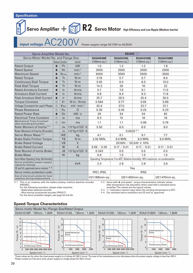
29
input voltage AC200V Power supply range AC170V to AC253V
Specification
Servo motor Model No./Flange Size/Rated Output
R2AA10100F/100mm/1.0kW R2AA13120L/130mm/1.2kW R2AA13180H/130mm/1.8kWR2AA13120D/130mm/1.2kW
These values are for when the input power supply is a 3-phase AC 200 V circuit. The area of the instantaneous zone decreases when the power supply voltage is less than 200 V.
Please contact us if the servo amp. power supply is a single-phase AC 200 V circuit.
Speed (min-1)
To
rqu
e (
N・
m)
Speed (min-1)
To
rqu
e (
N・
m)
Speed (min-1)
To
rqu
e (
N・
m)
Speed (min-1)
To
rqu
e (
N・
m)
10
4000
4
2
00
6
8
20001000 3000 5000 6000
16
14
12
25
20
15
10
5
01000 2000 40003000
25
20
15
10
5
010000 0 2000 3000 4000 5000 6000
20
25
10
15
5
010000 2000 3000 4000
Instantaneous Zone
Instantaneous Zone
Instantaneous Zone
Continuous Zone Continuous ZoneContinuous Zone
Instantaneous Zone
Continuous Zone
Servo Amplifi er + R2 Servo Motor High Effi ciency and Low Ripple (Medium Inertia)
Servo Amplifi er Model No. RS2A05□□Servo Motor Model No. and Flange Size R2AA10100F
《100mm sq.》R2AA13120L《130mm sq.》
R2AA13120D《130mm sq.》
R2AA13180H《130mm sq.》Status Symbol Unit
Rated Output ★ PR kW 1.0 1.2 1.2 1.8
Rated Speed ★ NR min-1 3000 2000 2000 2000
Maximum Speed ★ Nmax min-1 6000 3000 5000 3500
Rated Torque ★ TR N・m 3.18 5.7 5.7 8.6
Continuous Stall Torque ★ TS N・m 3.92 6.0 6.0 10.0
Peak Stall Torque ★ TP N・m 14.3 20 16 22
Rated Armature Current ★ IR Arms 5.7 7.6 9.1 11.0
Armature Stall Current ★ IS Arms 6.8 8.4 9.3 11.8
Peak Armature Stall Current ★ IP Arms 25.7 26.5 25.4 26.5
Torque Constant ☆ KT N・m/Arms 0.584 0.77 0.65 0.89
Voltage Constant for each Phase ☆ KEφ mV/min-1 20.4 27.0 22.7 31.1
Phase Resistance ☆ Rφ Ω 0.35 0.35 0.23 0.23
Rated Power Rate ★ QR kW/s 29 54 54 82
Electrical Time Constant ☆ te ms 8.3 15 16 18Mechanical Time Constant
(Not including Encoder) ☆ tm ms 1.1 1.1 0.98 0.78
Roter Moment of Inertia※ 1 JM ×10-4kg・m2(GD2/4) 3.50 6.0 6.0 9.0
Roter Moment of Inertia (Encoder) JS ×10-4kg・m2(GD2/4) 0.0033※ 1
Servo Motor Mass※ 1 WE kg 4.1 6.1 6.1 7.7
Brake Static Friction Torque TB N・m 3.92 MIN. 9.0 MIN. 9.0 MIN. 9.0 MIN.
Brake Rated Voltage VB V DC90V/ DC24V± 10%Brake Rated Current IB A 0.09/ 0.30 0.17/ 0.51 0.17/ 0.51 0.17/ 0.51
Roter Moment of Inertia (Brake) JB ×10-4kg・m2(GD2/4) 0.343 0.5 0.5 0.5
Brake Mass W kg 0.9 1.5 1.5 1.5
Servo Motor Operating Temp, Rel.Humidity Operating Temperature: 0 to 40℃, Relative Humidity: 90% maximum, no condensationServo amplifi er power supply
capacity (rating) kVA 2.3 2.8 2.8 3.6
CE and UL approved servo motors※ 4 Yes
Servo motor protection code IP67, IP65 IP65
Size of aluminum plates for heat
radiation during measurement t12×305mm sq. t20×400mm sq. t20×470mm sq.
Speed-Torque Characteristics
※ 1 This is an instance with the battery-backup method absolute encoder
[PA035C].
For the following encoders, please make inquiries:
・Batteryless absolute encoder
・Wire-saving incremental encoder [PP031T]
For the servo amplifi er weight, see page 53 and 54.
※ 2 Items with ★ and speed - torque characteristics indicate values
after temperature rise saturation when used with a standard servo
amplifi er. The values are the typical values.
※ 3 ☆ : Indicates a typical value when the winding temperature is 20℃ .
※ 4 Our standard servo amplifi ers are CE and UL approved.
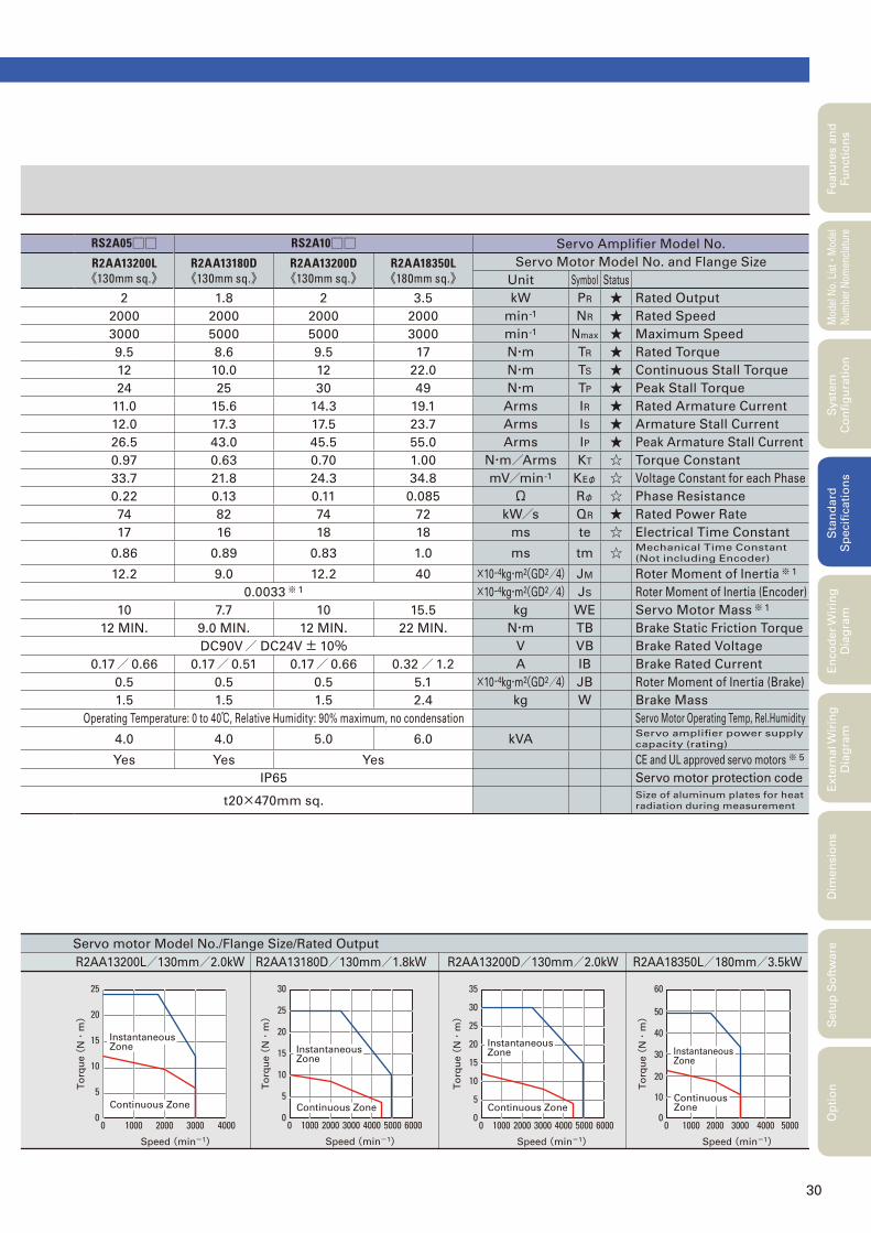
30
Servo motor Model No./Flange Size/Rated Output
R2AA13180D/130mm/1.8kWR2AA13200L/130mm/2.0kW R2AA18350L/180mm/3.5kWR2AA13200D/130mm/2.0kW
Speed (min-1)
To
rqu
e (
N・
m)
Speed (min-1)
To
rqu
e (
N・
m)
Speed (min-1)
To
rqu
e (
N・
m)
Speed (min-1)
To
rqu
e (
N・
m)
35
30
20
25
10
15
5
010000 2000 3000 4000 5000 6000
30
20
25
10
15
5
010000 2000 3000 4000 5000 6000
60
50
40
20
30
10
010000 2000 3000 4000 5000
25
20
15
10
5
01000 2000 400030000
Instantaneous Zone
Continuous Zone
Instantaneous Zone
Continuous Zone
Instantaneous Zone
Continuous Zone
Instantaneous Zone
Continuous Zone
Featu
res a
nd
Fu
ncti
on
sM
odel
No.
Lis
t
・Mod
el
Num
ber
Nom
encl
atur
eS
tan
dard
S
pecifi
cati
on
sE
nco
der
Wir
ing
D
iag
ram
Exte
rnal W
irin
g
Dia
gra
mD
imen
sio
ns
Setu
p S
oft
ware
Op
tio
nS
yste
m
Co
nfi
gu
rati
on
RS2A05□□ RS2A10□□ Servo Amplifi er Model No.
R2AA13200L《130mm sq.》
R2AA13180D《130mm sq.》
R2AA13200D《130mm sq.》
R2AA18350L《180mm sq.》
Servo Motor Model No. and Flange Size
Unit Symbol Status
2 1.8 2 3.5 kW PR ★ Rated Output
2000 2000 2000 2000 min-1 NR ★ Rated Speed
3000 5000 5000 3000 min-1 Nmax ★ Maximum Speed
9.5 8.6 9.5 17 N・m TR ★ Rated Torque
12 10.0 12 22.0 N・m TS ★ Continuous Stall Torque
24 25 30 49 N・m TP ★ Peak Stall Torque
11.0 15.6 14.3 19.1 Arms IR ★ Rated Armature Current
12.0 17.3 17.5 23.7 Arms IS ★ Armature Stall Current
26.5 43.0 45.5 55.0 Arms IP ★ Peak Armature Stall Current
0.97 0.63 0.70 1.00 N・m/Arms KT ☆ Torque Constant
33.7 21.8 24.3 34.8 mV/min-1 KEφ ☆ Voltage Constant for each Phase
0.22 0.13 0.11 0.085 Ω Rφ ☆ Phase Resistance
74 82 74 72 kW/s QR ★ Rated Power Rate
17 16 18 18 ms te ☆ Electrical Time Constant
0.86 0.89 0.83 1.0 ms tm ☆ Mechanical Time Constant
(Not including Encoder)
12.2 9.0 12.2 40 ×10-4kg・m2(GD2/4) JM Roter Moment of Inertia※ 1
0.0033※ 1 ×10⁻⁴kg・m2(GD2/4) JS Roter Moment of Inertia (Encoder)
10 7.7 10 15.5 kg WE Servo Motor Mass※ 1
12 MIN. 9.0 MIN. 12 MIN. 22 MIN. N・m TB Brake Static Friction Torque
DC90V/ DC24V± 10% V VB Brake Rated Voltage
0.17/ 0.66 0.17/ 0.51 0.17/ 0.66 0.32/1.2 A IB Brake Rated Current
0.5 0.5 0.5 5.1 ×10⁻⁴kg・m2(GD2/4) JB Roter Moment of Inertia (Brake)
1.5 1.5 1.5 2.4 kg W Brake Mass
Operating Temperature: 0 to 40℃, Relative Humidity: 90% maximum, no condensation Servo Motor Operating Temp, Rel.Humidity
4.0 4.0 5.0 6.0 kVAServo amplifi er power supply
capacity (rating)
Yes Yes Yes CE and UL approved servo motors※ 5
IP65 Servo motor protection code
t20×470mm sq.Size of aluminum plates for heat
radiation during measurement
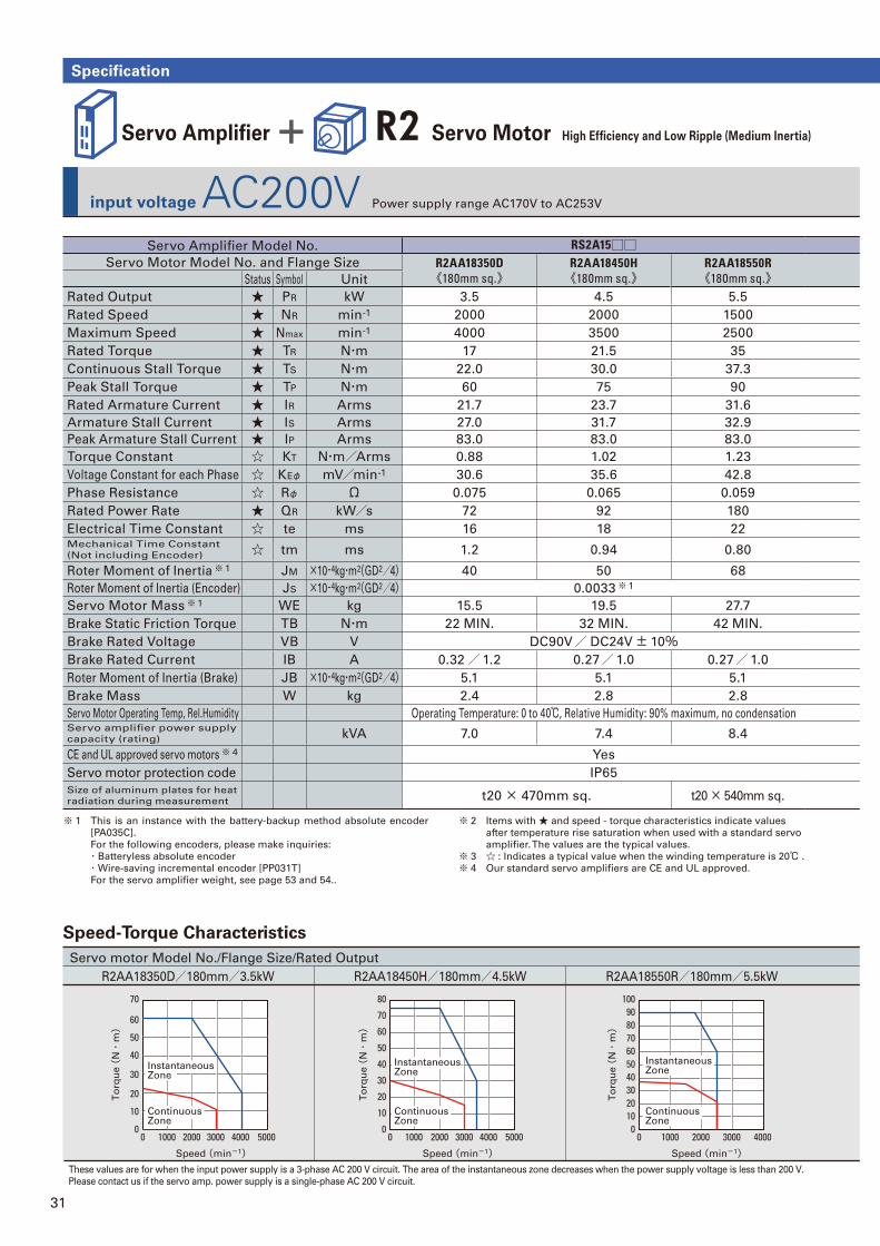
31
input voltage AC200V Power supply range AC170V to AC253V
Specification
Servo motor Model No./Flange Size/Rated Output
R2AA18350D/180mm/3.5kW R2AA18450H/180mm/4.5kW R2AA18550R/180mm/5.5kW
These values are for when the input power supply is a 3-phase AC 200 V circuit. The area of the instantaneous zone decreases when the power supply voltage is less than 200 V.
Please contact us if the servo amp. power supply is a single-phase AC 200 V circuit.
Speed (min-1)Speed (min-1)
To
rqu
e (
N・
m)
Speed (min-1)
To
rqu
e (
N・
m)
To
rqu
e (
N・
m)
80
70
60
50
40
30
10
20
010000 2000 3000 4000 5000
100
708090
60504030
1020
010000 2000 3000 4000
70
60
50
40
30
10
20
01000 2000 3000 40000 5000
Instantaneous Zone
Instantaneous Zone
Continuous Zone
Continuous Zone
Instantaneous Zone
Continuous Zone
Servo Amplifi er + R2 Servo Motor High Effi ciency and Low Ripple (Medium Inertia)
Servo Amplifi er Model No. RS2A15□□Servo Motor Model No. and Flange Size R2AA18350D
《180mm sq.》R2AA18450H《180mm sq.》
R2AA18550R《180mm sq.》Status Symbol Unit
Rated Output ★ PR kW 3.5 4.5 5.5
Rated Speed ★ NR min-1 2000 2000 1500
Maximum Speed ★ Nmax min-1 4000 3500 2500
Rated Torque ★ TR N・m 17 21.5 35
Continuous Stall Torque ★ TS N・m 22.0 30.0 37.3
Peak Stall Torque ★ TP N・m 60 75 90
Rated Armature Current ★ IR Arms 21.7 23.7 31.6
Armature Stall Current ★ IS Arms 27.0 31.7 32.9
Peak Armature Stall Current ★ IP Arms 83.0 83.0 83.0
Torque Constant ☆ KT N・m/Arms 0.88 1.02 1.23
Voltage Constant for each Phase ☆ KEφ mV/min-1 30.6 35.6 42.8
Phase Resistance ☆ Rφ Ω 0.075 0.065 0.059
Rated Power Rate ★ QR kW/s 72 92 180
Electrical Time Constant ☆ te ms 16 18 22Mechanical Time Constant
(Not including Encoder) ☆ tm ms 1.2 0.94 0.80
Roter Moment of Inertia※ 1 JM ×10-4kg・m2(GD2/4) 40 50 68
Roter Moment of Inertia (Encoder) JS ×10-4kg・m2(GD2/4) 0.0033※ 1
Servo Motor Mass※ 1 WE kg 15.5 19.5 27.7
Brake Static Friction Torque TB N・m 22 MIN. 32 MIN. 42 MIN.
Brake Rated Voltage VB V DC90V/ DC24V± 10%Brake Rated Current IB A 0.32/1.2 0.27/1.0 0.27/1.0
Roter Moment of Inertia (Brake) JB ×10-4kg・m2(GD2/4) 5.1 5.1 5.1
Brake Mass W kg 2.4 2.8 2.8
Servo Motor Operating Temp, Rel.Humidity Operating Temperature: 0 to 40℃, Relative Humidity: 90% maximum, no condensationServo amplifi er power supply
capacity (rating) kVA 7.0 7.4 8.4
CE and UL approved servo motors※ 4 Yes
Servo motor protection code IP65
Size of aluminum plates for heat
radiation during measurement t20 × 470mm sq. t20 × 540mm sq.
Speed-Torque Characteristics
※ 1 This is an instance with the battery-backup method absolute encoder
[PA035C].
For the following encoders, please make inquiries:
・Batteryless absolute encoder
・Wire-saving incremental encoder [PP031T]
For the servo amplifi er weight, see page 53 and 54..
※ 2 Items with ★ and speed - torque characteristics indicate values
after temperature rise saturation when used with a standard servo
amplifi er. The values are the typical values.
※ 3 ☆ : Indicates a typical value when the winding temperature is 20℃ .
※ 4 Our standard servo amplifi ers are CE and UL approved.
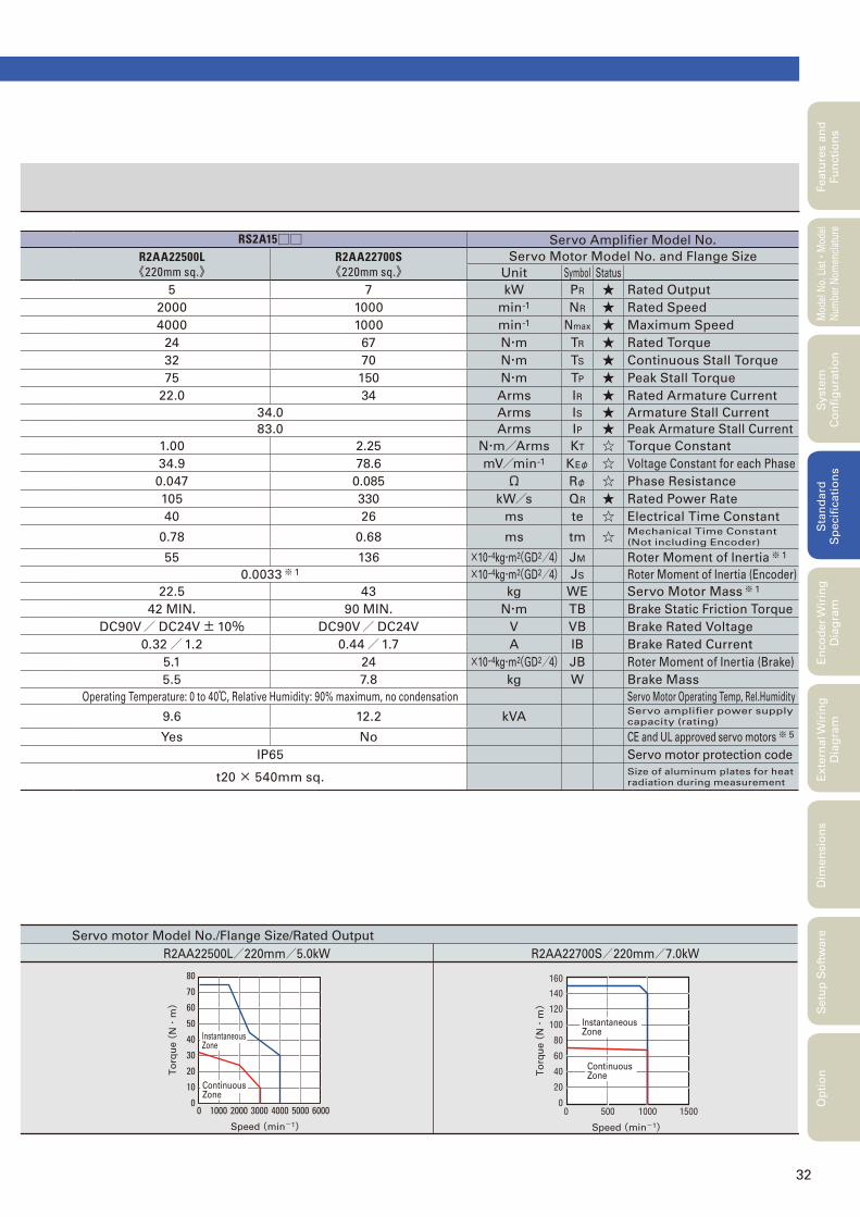
32
Servo motor Model No./Flange Size/Rated Output
R2AA22500L/220mm/5.0kW
Speed (min-1)
To
rqu
e (
N・
m)
80
70
60
50
40
30
10
20
010000 2000 3000 4000 5000 6000
Instantaneous Zone
Continuous Zone
R2AA22700S/220mm/7.0kW
5000 150010000
20
80
60
40
100
160
140
120Instantaneous Zone
Speed (min-1)
To
rqu
e (
N・
m)
Continuous Zone
Featu
res a
nd
Fu
ncti
on
sM
odel
No.
Lis
t
・Mod
el
Num
ber
Nom
encl
atur
eS
tan
dard
S
pecifi
cati
on
sE
nco
der
Wir
ing
D
iag
ram
Exte
rnal W
irin
g
Dia
gra
mD
imen
sio
ns
Setu
p S
oft
ware
Op
tio
nS
yste
m
Co
nfi
gu
rati
on
RS2A15□□ Servo Amplifi er Model No.
R2AA22500L《220mm sq.》
R2AA22700S《220mm sq.》
Servo Motor Model No. and Flange Size
Unit Symbol Status
5 7 kW PR ★ Rated Output
2000 1000 min-1 NR ★ Rated Speed
4000 1000 min-1 Nmax ★ Maximum Speed
24 67 N・m TR ★ Rated Torque
32 70 N・m TS ★ Continuous Stall Torque
75 150 N・m TP ★ Peak Stall Torque
22.0 34 Arms IR ★ Rated Armature Current
34.0 Arms IS ★ Armature Stall Current
83.0 Arms IP ★ Peak Armature Stall Current
1.00 2.25 N・m/Arms KT ☆ Torque Constant
34.9 78.6 mV/min-1 KEφ ☆ Voltage Constant for each Phase
0.047 0.085 Ω Rφ ☆ Phase Resistance
105 330 kW/s QR ★ Rated Power Rate
40 26 ms te ☆ Electrical Time Constant
0.78 0.68 ms tm ☆ Mechanical Time Constant
(Not including Encoder)
55 136 ×10-4kg・m2(GD2/4) JM Roter Moment of Inertia※ 1
0.0033※ 1 ×10⁻⁴kg・m2(GD2/4) JS Roter Moment of Inertia (Encoder)
22.5 43 kg WE Servo Motor Mass※ 1
42 MIN. 90 MIN. N・m TB Brake Static Friction Torque
DC90V/ DC24V± 10% DC90V/ DC24V V VB Brake Rated Voltage
0.32/1.2 0.44/1.7 A IB Brake Rated Current
5.1 24 ×10-4kg・m2(GD2/4) JB Roter Moment of Inertia (Brake)
5.5 7.8 kg W Brake Mass
Operating Temperature: 0 to 40℃, Relative Humidity: 90% maximum, no condensation Servo Motor Operating Temp, Rel.Humidity
9.6 12.2 kVAServo amplifi er power supply
capacity (rating)
Yes No CE and UL approved servo motors※ 5
IP65 Servo motor protection code
t20 × 540mm sq.Size of aluminum plates for heat
radiation during measurement
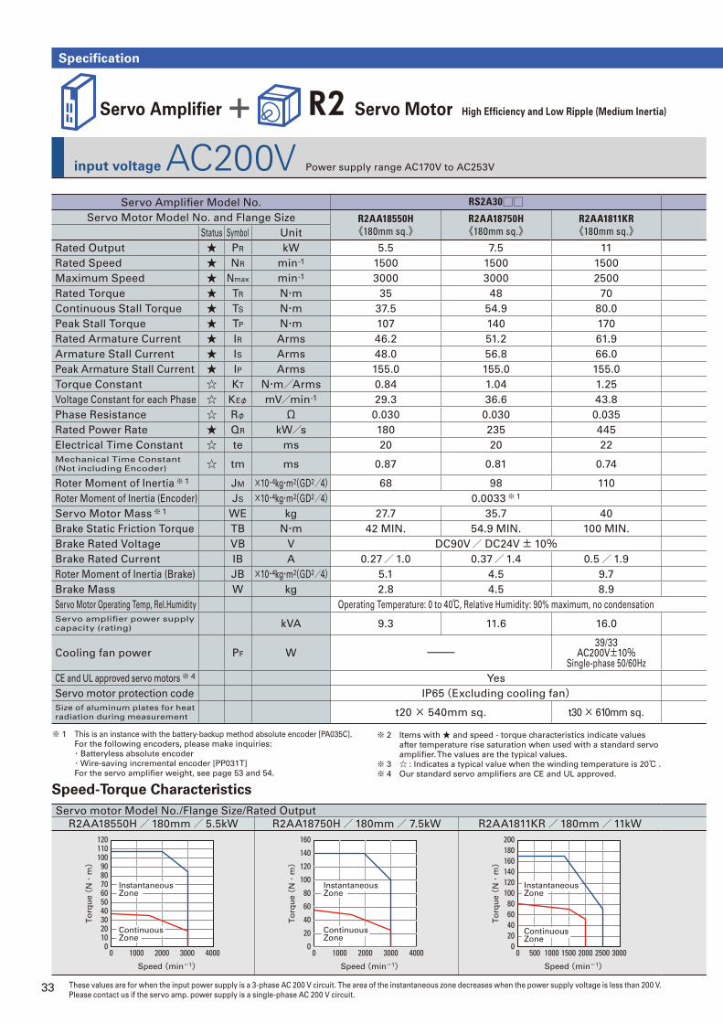
33
Specification
input voltage AC200V Power supply range AC170V to AC253V
Servo Amplifi er + R2 Servo Motor High Effi ciency and Low Ripple (Medium Inertia)
These values are for when the input power supply is a 3-phase AC 200 V circuit. The area of the instantaneous zone decreases when the power supply voltage is less than 200 V.
Please contact us if the servo amp. power supply is a single-phase AC 200 V circuit.
Servo motor Model No./Flange Size/Rated Output
R2AA18550H/180mm/ 5.5kW R2AA18750H/180mm/ 7.5kW R2AA1811KR/180mm/11kW
Speed (min-1)
To
rqu
e (
N・
m)
120
7080
100110
90
60504030
1020
010000 2000 3000 4000
Instantaneous Zone
Continuous Zone
Speed (min-1)
To
rqu
e (
N・
m)
160
140
120
100
80
60
20
40
010000 2000 3000 4000
Instantaneous Zone
Continuous Zone
Speed (min-1)
To
rqu
e (
N・
m)
200
140160180
120100
8060
2040
0500 10000 1500 2000 2500 3000
Instantaneous Zone
Continuous Zone
Servo Amplifi er Model No. RS2A30□□Servo Motor Model No. and Flange Size R2AA18550H
《180mm sq.》R2AA18750H《180mm sq.》
R2AA1811KR《180mm sq.》Status Symbol Unit
Rated Output ★ PR kW 5.5 7.5 11
Rated Speed ★ NR min-1 1500 1500 1500
Maximum Speed ★ Nmax min-1 3000 3000 2500
Rated Torque ★ TR N・m 35 48 70
Continuous Stall Torque ★ TS N・m 37.5 54.9 80.0
Peak Stall Torque ★ TP N・m 107 140 170
Rated Armature Current ★ IR Arms 46.2 51.2 61.9
Armature Stall Current ★ IS Arms 48.0 56.8 66.0
Peak Armature Stall Current ★ IP Arms 155.0 155.0 155.0
Torque Constant ☆ KT N・m/Arms 0.84 1.04 1.25
Voltage Constant for each Phase ☆ KEφ mV/min-1 29.3 36.6 43.8
Phase Resistance ☆ Rφ Ω 0.030 0.030 0.035
Rated Power Rate ★ QR kW/s 180 235 445
Electrical Time Constant ☆ te ms 20 20 22
Mechanical Time Constant
(Not including Encoder) ☆ tm ms 0.87 0.81 0.74
Roter Moment of Inertia※ 1 JM ×10-4kg・m2(GD2/4) 68 98 110
Roter Moment of Inertia (Encoder) JS ×10-4kg・m2(GD2/4) 0.0033※ 1
Servo Motor Mass※ 1 WE kg 27.7 35.7 40
Brake Static Friction Torque TB N・m 42 MIN. 54.9 MIN. 100 MIN.
Brake Rated Voltage VB V DC90V/ DC24V± 10%Brake Rated Current IB A 0.27/1.0 0.37/1.4 0.5/1.9
Roter Moment of Inertia (Brake) JB ×10-4kg・m2(GD2/4) 5.1 4.5 9.7
Brake Mass W kg 2.8 4.5 8.9
Servo Motor Operating Temp, Rel.Humidity Operating Temperature: 0 to 40℃, Relative Humidity: 90% maximum, no condensation
Servo amplifi er power supply
capacity (rating) kVA 9.3 11.6 16.0
Cooling fan power PF W ー39/33
AC200V±10%Single-phase 50/60Hz
CE and UL approved servo motors※ 4 Yes
Servo motor protection code IP65(Excluding cooling fan)Size of aluminum plates for heat
radiation during measurement t20 × 540mm sq. t30 × 610mm sq.
Speed-Torque Characteristics
※ 1 This is an instance with the battery-backup method absolute encoder [PA035C].
For the following encoders, please make inquiries:
・Batteryless absolute encoder
・Wire-saving incremental encoder [PP031T]
For the servo amplifi er weight, see page 53 and 54.
※ 2 Items with ★ and speed - torque characteristics indicate values
after temperature rise saturation when used with a standard servo
amplifi er. The values are the typical values.
※ 3 ☆ : Indicates a typical value when the winding temperature is 20℃ .
※ 4 Our standard servo amplifi ers are CE and UL approved.
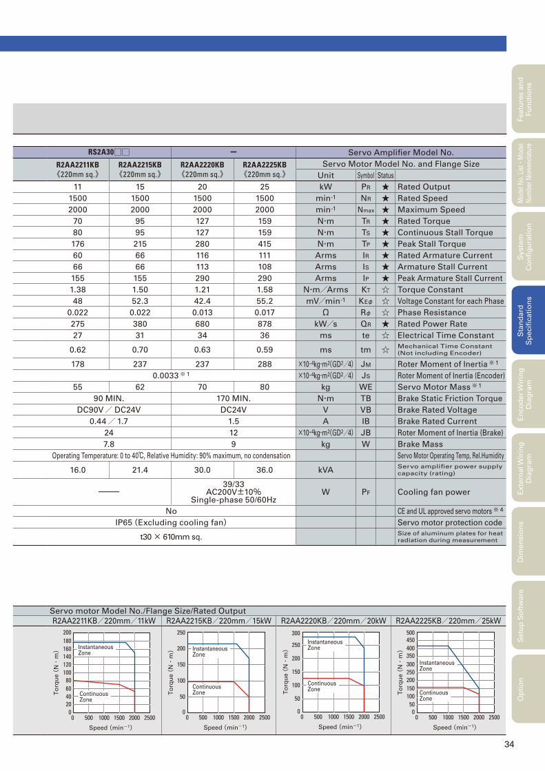
34
Featu
res a
nd
Fu
ncti
on
sM
odel
No.
Lis
t
・Mod
el
Num
ber
Nom
encl
atur
eS
tan
dard
S
pecifi
cati
on
sE
nco
der
Wir
ing
D
iag
ram
Exte
rnal W
irin
g
Dia
gra
mD
imen
sio
ns
Setu
p S
oft
ware
Op
tio
nS
yste
m
Co
nfi
gu
rati
on
Servo motor Model No./Flange Size/Rated Output
R2AA2211KB/220mm/11kW R2AA2215KB/220mm/15kW R2AA2220KB/220mm/20kW R2AA2225KB/220mm/25kW
5000 1500 2500200010000
20
806040
100
200180160140120
Instantaneous Zone
Speed (min-1)
To
rqu
e (
N・
m)
Continuous Zone
5000 1500 2500200010000
50
200
150
100
250
Instantaneous Zone
Speed (min-1)
To
rqu
e (
N・
m)
Continuous Zone
5000 1500 2500200010000
50
200
150
100
250
300Instantaneous Zone
Speed (min-1)
To
rqu
e (
N・
m)
Continuous Zone
5000 1500 20001000 25000
50
200150100
250
500450400350300 Instantaneous
Zone
Speed (min-1)
To
rqu
e (
N・
m)
Continuous Zone
RS2A30□□ - Servo Amplifi er Model No.
R2AA2211KB《220mm sq.》
R2AA2215KB《220mm sq.》
R2AA2220KB《220mm sq.》
R2AA2225KB《220mm sq.》
Servo Motor Model No. and Flange Size
Unit Symbol Status
11 15 20 25 kW PR ★ Rated Output
1500 1500 1500 1500 min-1 NR ★ Rated Speed
2000 2000 2000 2000 min-1 Nmax ★ Maximum Speed
70 95 127 159 N・m TR ★ Rated Torque
80 95 127 159 N・m TS ★ Continuous Stall Torque
176 215 280 415 N・m TP ★ Peak Stall Torque
60 66 116 111 Arms IR ★ Rated Armature Current
66 66 113 108 Arms IS ★ Armature Stall Current
155 155 290 290 Arms IP ★ Peak Armature Stall Current
1.38 1.50 1.21 1.58 N・m/Arms KT ☆ Torque Constant
48 52.3 42.4 55.2 mV/min-1 KEφ ☆ Voltage Constant for each Phase
0.022 0.022 0.013 0.017 Ω Rφ ☆ Phase Resistance
275 380 680 878 kW/s QR ★ Rated Power Rate
27 31 34 36 ms te ☆ Electrical Time Constant
0.62 0.70 0.63 0.59 ms tm ☆ Mechanical Time Constant
(Not including Encoder)
178 237 237 288 ×10-4kg・m2(GD2/4) JM Roter Moment of Inertia※ 1
0.0033※ 1 ×10⁻⁴kg・m2(GD2/4) JS Roter Moment of Inertia (Encoder)
55 62 70 80 kg WE Servo Motor Mass※ 1
90 MIN. 170 MIN. N・m TB Brake Static Friction Torque
DC90V/ DC24V DC24V V VB Brake Rated Voltage
0.44/1.7 1.5 A IB Brake Rated Current
24 12 ×10-4kg・m2(GD2/4) JB Roter Moment of Inertia (Brake)
7.8 9 kg W Brake Mass
Operating Temperature: 0 to 40℃, Relative Humidity: 90% maximum, no condensation Servo Motor Operating Temp, Rel.Humidity
16.0 21.4 30.0 36.0 kVAServo amplifi er power supply
capacity (rating)
ー39/33
AC200V±10%Single-phase 50/60Hz
W PF Cooling fan power
No CE and UL approved servo motors※ 4
IP65(Excluding cooling fan) Servo motor protection code
t30 × 610mm sq.Size of aluminum plates for heat
radiation during measurement
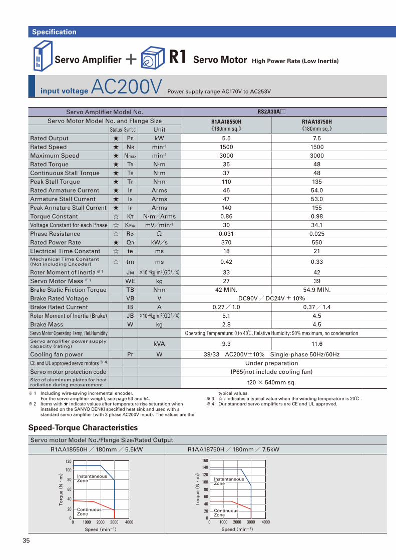
35
Specification
input voltage AC200V Power supply range AC170V to AC253V
Servo Amplifi er + R1 Servo Motor High Power Rate (Low Inertia)
Servo motor Model No./Flange Size/Rated Output
R1AA18550H/180mm/ 5.5kW R1AA18750H/180mm/ 7.5kW
Servo Amplifi er Model No. RS2A30A□Servo Motor Model No. and Flange Size R1AA18550H
《180mm sq.》R1AA18750H《180mm sq.》Status Symbol Unit
Rated Output ★ PR kW 5.5 7.5
Rated Speed ★ NR min-1 1500 1500
Maximum Speed ★ Nmax min-1 3000 3000
Rated Torque ★ TR N・m 35 48
Continuous Stall Torque ★ TS N・m 37 48
Peak Stall Torque ★ TP N・m 110 135
Rated Armature Current ★ IR Arms 46 54.0
Armature Stall Current ★ IS Arms 47 53.0
Peak Armature Stall Current ★ IP Arms 140 155
Torque Constant ☆ KT N・m/Arms 0.86 0.98
Voltage Constant for each Phase ☆ KEφ mV/min-1 30 34.1
Phase Resistance ☆ Rφ Ω 0.031 0.025
Rated Power Rate ★ QR kW/s 370 550
Electrical Time Constant ☆ te ms 18 21
Mechanical Time Constant
(Not including Encoder) ☆ tm ms 0.42 0.33
Roter Moment of Inertia※ 1 JM ×10-4kg・m2(GD2/4) 33 42
Servo Motor Mass※ 1 WE kg 27 39
Brake Static Friction Torque TB N・m 42 MIN. 54.9 MIN.
Brake Rated Voltage VB V DC90V/ DC24V± 10%Brake Rated Current IB A 0.27/1.0 0.37/1.4
Roter Moment of Inertia (Brake) JB ×10-4kg・m2(GD2/4) 5.1 4.5
Brake Mass W kg 2.8 4.5
Servo Motor Operating Temp, Rel.Humidity Operating Temperature: 0 to 40℃, Relative Humidity: 90% maximum, no condensation
Servo amplifi er power supply
capacity (rating) kVA 9.3 11.6
Cooling fan power PF W 39/33 AC200V±10% Single-phase 50Hz/60Hz
CE and UL approved servo motors※ 4 Under preparation
Servo motor protection code IP65(not include cooling fan)
Size of aluminum plates for heat
radiation during measurement t20 × 540mm sq.
typical values.
※ 3 ☆ : Indicates a typical value when the winding temperature is 20℃ .
※ 4 Our standard servo amplifi ers are CE and UL approved.
Speed-Torque Characteristics
※ 1 Including wire-saving incremental encoder.
For the servo amplifi er weight, see page 53 and 54.
※ 2 Items with ★ indicate values after temperature rise saturation when
installed on the SANYO DENKI specifi ed heat sink and used with a
standard servo amplifi er (with 3 phase AC200V input). The values are the
10000 2000 3000 40000
20
80
60
40
100
120
Instantaneous Zone
Continuous Zone
Speed (min-1)
To
rqu
e (
N・
m)
10000 2000 3000 40000
20
80
60
40
100
120
140160
Instantaneous Zone
Continuous Zone
Speed (min-1)
To
rqu
e (
N・
m)
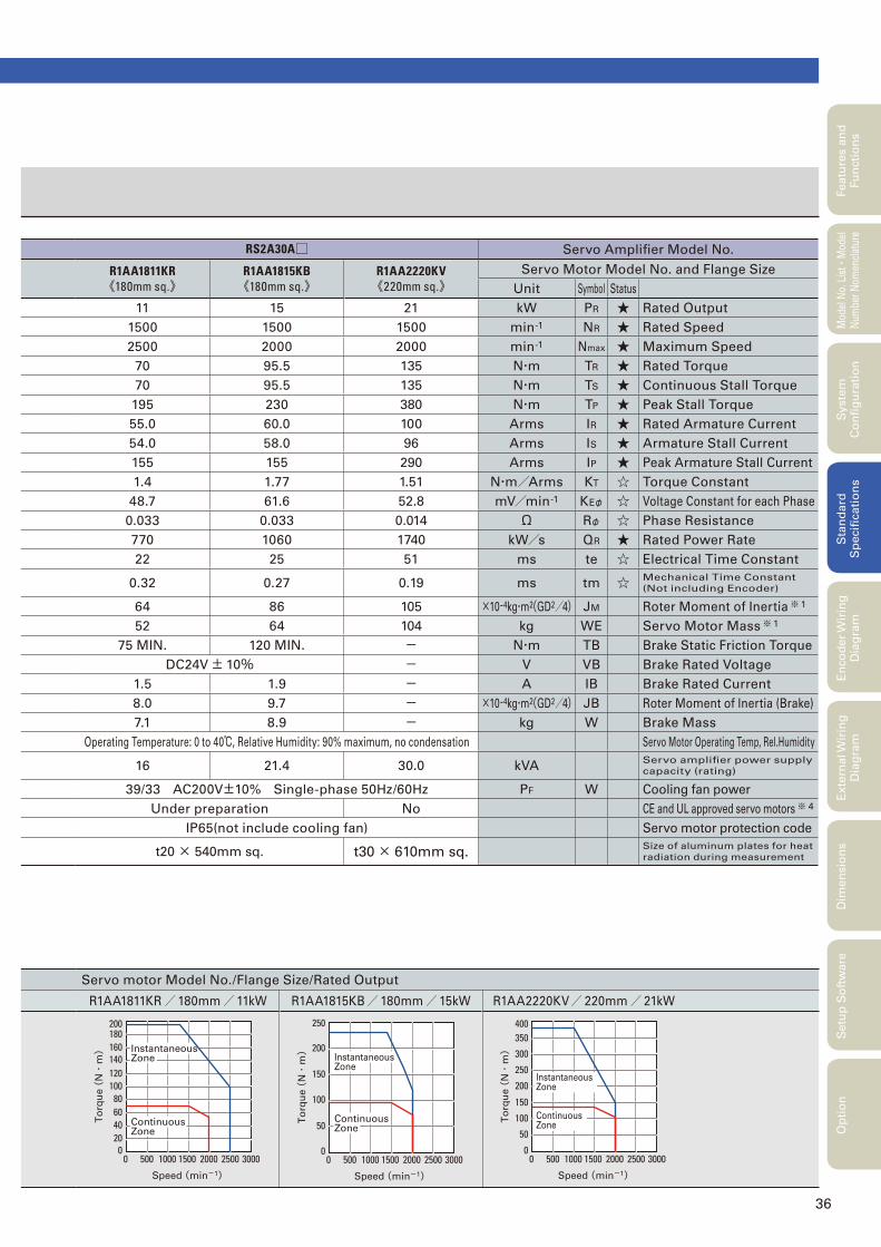
36
Featu
res a
nd
Fu
ncti
on
sM
odel
No.
Lis
t
・Mod
el
Num
ber
Nom
encl
atur
eS
tan
dard
S
pecifi
cati
on
sE
nco
der
Wir
ing
D
iag
ram
Exte
rnal W
irin
g
Dia
gra
mD
imen
sio
ns
Setu
p S
oft
ware
Op
tio
nS
yste
m
Co
nfi
gu
rati
on
Servo motor Model No./Flange Size/Rated Output
R1AA1811KR/180mm/11kW R1AA1815KB/180mm/15kW R1AA2220KV/ 220mm/ 21kW
5000 1500 250020001000 30000
20
806040
100
200180160140120
Instantaneous Zone
Continuous Zone
Speed (min-1)
To
rqu
e (
N・
m)
5000 1500 250020001000 30000
100
50
250
200
150
Continuous Zone
Instantaneous Zone
Speed (min-1)
To
rqu
e (
N・
m)
5000 1500 250020001000 30000
100
50
150
400350
300
250
200Instantaneous Zone
Speed (min-1)
To
rqu
e (
N・
m)
Continuous Zone
RS2A30A□ Servo Amplifi er Model No.
R1AA1811KR《180mm sq.》
R1AA1815KB《180mm sq.》
R1AA2220KV《220mm sq.》
Servo Motor Model No. and Flange Size
Unit Symbol Status
11 15 21 kW PR ★ Rated Output
1500 1500 1500 min-1 NR ★ Rated Speed
2500 2000 2000 min-1 Nmax ★ Maximum Speed
70 95.5 135 N・m TR ★ Rated Torque
70 95.5 135 N・m TS ★ Continuous Stall Torque
195 230 380 N・m TP ★ Peak Stall Torque
55.0 60.0 100 Arms IR ★ Rated Armature Current
54.0 58.0 96 Arms IS ★ Armature Stall Current
155 155 290 Arms IP ★ Peak Armature Stall Current
1.4 1.77 1.51 N・m/Arms KT ☆ Torque Constant
48.7 61.6 52.8 mV/min-1 KEφ ☆ Voltage Constant for each Phase
0.033 0.033 0.014 Ω Rφ ☆ Phase Resistance
770 1060 1740 kW/s QR ★ Rated Power Rate
22 25 51 ms te ☆ Electrical Time Constant
0.32 0.27 0.19 ms tm ☆ Mechanical Time Constant
(Not including Encoder)
64 86 105 ×10-4kg・m2(GD2/4) JM Roter Moment of Inertia※ 1
52 64 104 kg WE Servo Motor Mass※ 1
75 MIN. 120 MIN. - N・m TB Brake Static Friction Torque
DC24V± 10% - V VB Brake Rated Voltage
1.5 1.9 - A IB Brake Rated Current
8.0 9.7 - ×10-4kg・m2(GD2/4) JB Roter Moment of Inertia (Brake)
7.1 8.9 - kg W Brake Mass
Operating Temperature: 0 to 40℃, Relative Humidity: 90% maximum, no condensation Servo Motor Operating Temp, Rel.Humidity
16 21.4 30.0 kVAServo amplifi er power supply
capacity (rating)
39/33 AC200V±10% Single-phase 50Hz/60Hz PF W Cooling fan power
Under preparation No CE and UL approved servo motors※ 4
IP65(not include cooling fan) Servo motor protection code
t20 × 540mm sq. t30 × 610mm sq.Size of aluminum plates for heat
radiation during measurement
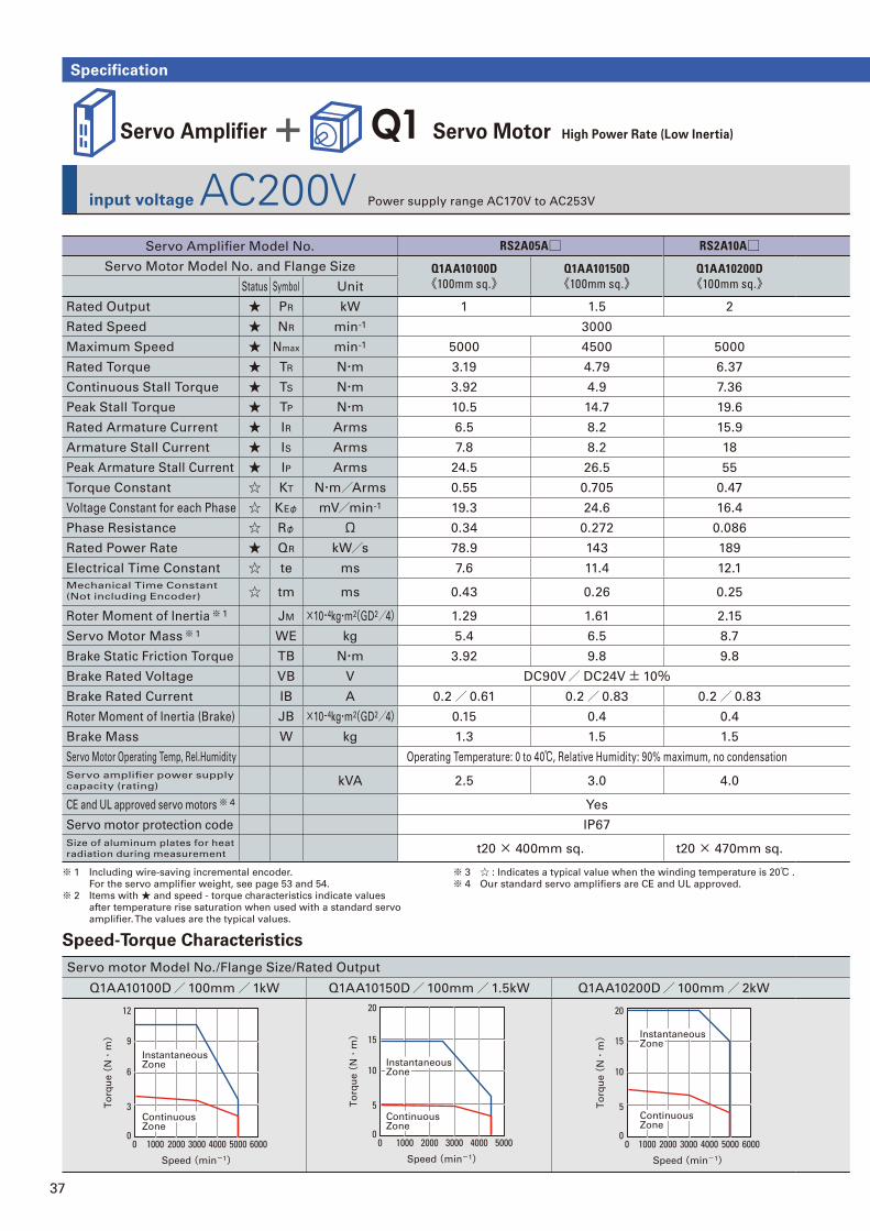
37
Specification
input voltage AC200V Power supply range AC170V to AC253V
Servo Amplifi er + Q1 Servo Motor High Power Rate (Low Inertia)
Servo motor Model No./Flange Size/Rated Output
Q1AA10100D/100mm/1kW Q1AA10150D/100mm/1.5kW Q1AA10200D/100mm/ 2kW
Servo Amplifi er Model No. RS2A05A□ RS2A10A□Servo Motor Model No. and Flange Size Q1AA10100D
《100mm sq.》Q1AA10150D《100mm sq.》
Q1AA10200D《100mm sq.》Status Symbol Unit
Rated Output ★ PR kW 1 1.5 2
Rated Speed ★ NR min-1 3000
Maximum Speed ★ Nmax min-1 5000 4500 5000
Rated Torque ★ TR N・m 3.19 4.79 6.37
Continuous Stall Torque ★ TS N・m 3.92 4.9 7.36
Peak Stall Torque ★ TP N・m 10.5 14.7 19.6
Rated Armature Current ★ IR Arms 6.5 8.2 15.9
Armature Stall Current ★ IS Arms 7.8 8.2 18
Peak Armature Stall Current ★ IP Arms 24.5 26.5 55
Torque Constant ☆ KT N・m/Arms 0.55 0.705 0.47
Voltage Constant for each Phase ☆ KEφ mV/min-1 19.3 24.6 16.4
Phase Resistance ☆ Rφ Ω 0.34 0.272 0.086
Rated Power Rate ★ QR kW/s 78.9 143 189
Electrical Time Constant ☆ te ms 7.6 11.4 12.1
Mechanical Time Constant
(Not including Encoder) ☆ tm ms 0.43 0.26 0.25
Roter Moment of Inertia※ 1 JM ×10-4kg・m2(GD2/4) 1.29 1.61 2.15
Servo Motor Mass※ 1 WE kg 5.4 6.5 8.7
Brake Static Friction Torque TB N・m 3.92 9.8 9.8
Brake Rated Voltage VB V DC90V/ DC24V± 10%Brake Rated Current IB A 0.2/ 0.61 0.2/ 0.83 0.2/ 0.83
Roter Moment of Inertia (Brake) JB ×10-4kg・m2(GD2/4) 0.15 0.4 0.4
Brake Mass W kg 1.3 1.5 1.5
Servo Motor Operating Temp, Rel.Humidity Operating Temperature: 0 to 40℃, Relative Humidity: 90% maximum, no condensation
Servo amplifi er power supply
capacity (rating) kVA 2.5 3.0 4.0
CE and UL approved servo motors※ 4 Yes
Servo motor protection code IP67
Size of aluminum plates for heat
radiation during measurement t20 × 400mm sq. t20 × 470mm sq.
10000 2000 3000 4000 5000 60000
3
6
9
12
Instantaneous Zone
Continuous Zone
Speed (min-1)
To
rqu
e (
N・
m)
30000 50004000200010000
5
10
15
20
Speed (min-1)
To
rqu
e (
N・
m)
Instantaneous Zone
Continuous Zone
30000 600050004000200010000
5
10
15
20
Speed (min-1)
To
rqu
e (
N・
m) Instantaneous
Zone
Continuous Zone
Speed-Torque Characteristics
※ 1 Including wire-saving incremental encoder.
For the servo amplifi er weight, see page 53 and 54.
※ 2 Items with ★ and speed - torque characteristics indicate values
after temperature rise saturation when used with a standard servo
amplifi er. The values are the typical values.
※ 3 ☆ : Indicates a typical value when the winding temperature is 20℃ .
※ 4 Our standard servo amplifi ers are CE and UL approved.
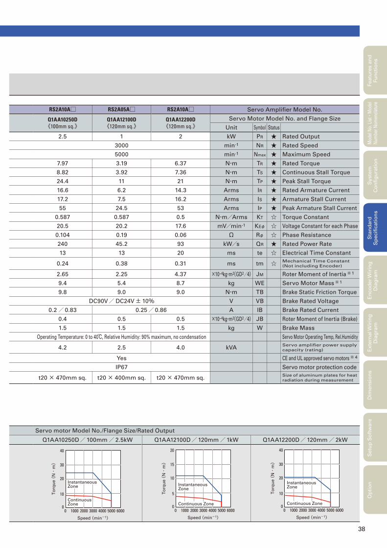
38
Featu
res a
nd
Fu
ncti
on
sM
odel
No.
Lis
t
・Mod
el
Num
ber
Nom
encl
atur
eS
tan
dard
S
pecifi
cati
on
sE
nco
der
Wir
ing
D
iag
ram
Exte
rnal W
irin
g
Dia
gra
mD
imen
sio
ns
Setu
p S
oft
ware
Op
tio
nS
yste
m
Co
nfi
gu
rati
on
Servo motor Model No./Flange Size/Rated Output
Q1AA10250D/100mm/ 2.5kW Q1AA12100D/120mm/1kW Q1AA12200D/120mm/ 2kW
RS2A10A□ RS2A05A□ RS2A10A□ Servo Amplifi er Model No.
Q1AA10250D《100mm sq.》
Q1AA12100D《120mm sq.》
Q1AA12200D《120mm sq.》
Servo Motor Model No. and Flange Size
Unit Symbol Status
2.5 1 2 kW PR ★ Rated Output
3000 min-1 NR ★ Rated Speed
5000 min-1 Nmax ★ Maximum Speed
7.97 3.19 6.37 N・m TR ★ Rated Torque
8.82 3.92 7.36 N・m TS ★ Continuous Stall Torque
24.4 11 21 N・m TP ★ Peak Stall Torque
16.6 6.2 14.3 Arms IR ★ Rated Armature Current
17.2 7.5 16.2 Arms IS ★ Armature Stall Current
55 24.5 53 Arms IP ★ Peak Armature Stall Current
0.587 0.587 0.5 N・m/Arms KT ☆ Torque Constant
20.5 20.2 17.6 mV/min-1 KEφ ☆ Voltage Constant for each Phase
0.104 0.19 0.06 Ω Rφ ☆ Phase Resistance
240 45.2 93 kW/s QR ★ Rated Power Rate
13 13 20 ms te ☆ Electrical Time Constant
0.24 0.38 0.31 ms tm ☆ Mechanical Time Constant
(Not including Encoder)
2.65 2.25 4.37 ×10⁻⁴kg・m2(GD2/4) JM Roter Moment of Inertia※ 1
9.4 5.4 8.7 kg WE Servo Motor Mass※ 1
9.8 9.0 9.0 N・m TB Brake Static Friction Torque
DC90V/ DC24V± 10% V VB Brake Rated Voltage
0.2/ 0.83 0.25/ 0.86 A IB Brake Rated Current
0.4 0.5 0.5 ×10⁻⁴kg・m2(GD2/4) JB Roter Moment of Inertia (Brake)
1.5 1.5 1.5 kg W Brake Mass
Operating Temperature: 0 to 40℃, Relative Humidity: 90% maximum, no condensation Servo Motor Operating Temp, Rel.Humidity
4.2 2.5 4.0 kVAServo amplifi er power supply
capacity (rating)
Yes CE and UL approved servo motors※ 4
IP67 Servo motor protection code
t20 × 470mm sq. t20 × 400mm sq. t20 × 470mm sq.Size of aluminum plates for heat
radiation during measurement
10000 2000 3000 4000 5000 60000
10
20
30
40
Speed (min-1)
To
rqu
e (
N・
m)
Instantaneous Zone
Continuous Zone
10000 2000 3000 4000 5000 60000
5
10
15
20
Speed (min-1)
To
rqu
e (
N・
m)
Instantaneous Zone
Continuous Zone
10000 2000 3000 4000 5000 60000
10
20
30
40
Speed (min-1)
To
rqu
e (
N・
m)
Instantaneous Zone
Continuous Zone
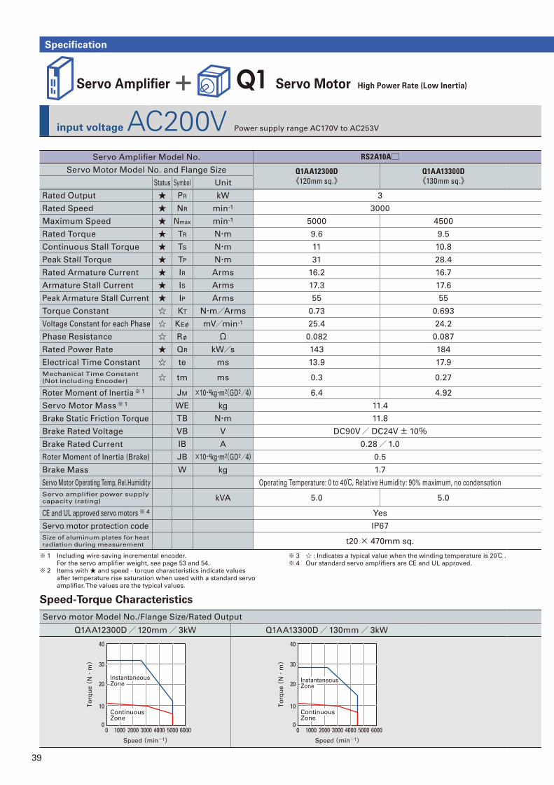
39
Specification
input voltage AC200V Power supply range AC170V to AC253V
Servo Amplifi er + Q1 Servo Motor High Power Rate (Low Inertia)
Servo motor Model No./Flange Size/Rated Output
Q1AA12300D/120mm/ 3kW Q1AA13300D/130mm/ 3kW
10000 2000 3000 4000 5000 60000
10
20
30
40
Instantaneous Zone
Continuous Zone
Speed (min-1)
To
rqu
e (
N・
m)
10000 2000 3000 4000 5000 60000
10
20
30
40
Instantaneous Zone
Continuous Zone
Speed (min-1)
To
rqu
e (
N・
m)
Servo Amplifi er Model No. RS2A10A□Servo Motor Model No. and Flange Size Q1AA12300D
《120mm sq.》Q1AA13300D《130mm sq.》Status Symbol Unit
Rated Output ★ PR kW 3
Rated Speed ★ NR min-1 3000
Maximum Speed ★ Nmax min-1 5000 4500
Rated Torque ★ TR N・m 9.6 9.5
Continuous Stall Torque ★ TS N・m 11 10.8
Peak Stall Torque ★ TP N・m 31 28.4
Rated Armature Current ★ IR Arms 16.2 16.7
Armature Stall Current ★ IS Arms 17.3 17.6
Peak Armature Stall Current ★ IP Arms 55 55
Torque Constant ☆ KT N・m/Arms 0.73 0.693
Voltage Constant for each Phase ☆ KEφ mV/min-1 25.4 24.2
Phase Resistance ☆ Rφ Ω 0.082 0.087
Rated Power Rate ★ QR kW/s 143 184
Electrical Time Constant ☆ te ms 13.9 17.9
Mechanical Time Constant
(Not including Encoder) ☆ tm ms 0.3 0.27
Roter Moment of Inertia※ 1 JM ×10-4kg・m2(GD2/4) 6.4 4.92
Servo Motor Mass※ 1 WE kg 11.4
Brake Static Friction Torque TB N・m 11.8
Brake Rated Voltage VB V DC90V/ DC24V± 10%Brake Rated Current IB A 0.28/1.0
Roter Moment of Inertia (Brake) JB ×10-4kg・m2(GD2/4) 0.5
Brake Mass W kg 1.7
Servo Motor Operating Temp, Rel.Humidity Operating Temperature: 0 to 40℃, Relative Humidity: 90% maximum, no condensation
Servo amplifi er power supply
capacity (rating) kVA 5.0 5.0
CE and UL approved servo motors※ 4 Yes
Servo motor protection code IP67
Size of aluminum plates for heat
radiation during measurement t20 × 470mm sq.
Speed-Torque Characteristics
※ 1 Including wire-saving incremental encoder.
For the servo amplifi er weight, see page 53 and 54.
※ 2 Items with ★ and speed - torque characteristics indicate values
after temperature rise saturation when used with a standard servo
amplifi er. The values are the typical values.
※ 3 ☆ : Indicates a typical value when the winding temperature is 20℃ .
※ 4 Our standard servo amplifi ers are CE and UL approved.
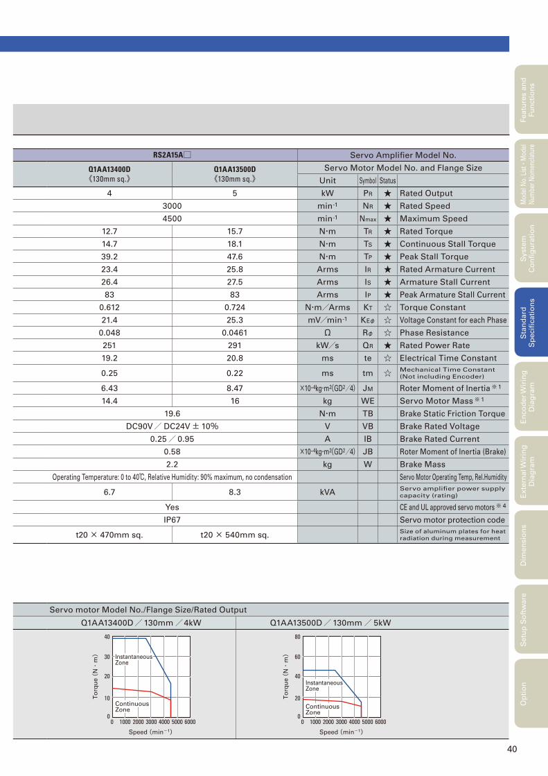
40
Featu
res a
nd
Fu
ncti
on
sM
odel
No.
Lis
t
・Mod
el
Num
ber
Nom
encl
atur
eS
tan
dard
S
pecifi
cati
on
sE
nco
der
Wir
ing
D
iag
ram
Exte
rnal W
irin
g
Dia
gra
mD
imen
sio
ns
Setu
p S
oft
ware
Op
tio
nS
yste
m
Co
nfi
gu
rati
on
Servo motor Model No./Flange Size/Rated Output
Q1AA13400D/130mm/4kW Q1AA13500D/130mm/ 5kW
10000 2000 3000 4000 5000 60000
10
20
30
40
Instantaneous Zone
Continuous Zone
Speed (min-1)
To
rqu
e (
N・
m)
30000 600050004000200010000
20
40
60
80
Instantaneous Zone
Continuous Zone
Speed (min-1)
To
rqu
e (
N・
m)
RS2A15A□ Servo Amplifi er Model No.
Q1AA13400D《130mm sq.》
Q1AA13500D《130mm sq.》
Servo Motor Model No. and Flange Size
Unit Symbol Status
4 5 kW PR ★ Rated Output
3000 min-1 NR ★ Rated Speed
4500 min-1 Nmax ★ Maximum Speed
12.7 15.7 N・m TR ★ Rated Torque
14.7 18.1 N・m TS ★ Continuous Stall Torque
39.2 47.6 N・m TP ★ Peak Stall Torque
23.4 25.8 Arms IR ★ Rated Armature Current
26.4 27.5 Arms IS ★ Armature Stall Current
83 83 Arms IP ★ Peak Armature Stall Current
0.612 0.724 N・m/Arms KT ☆ Torque Constant
21.4 25.3 mV/min-1 KEφ ☆ Voltage Constant for each Phase
0.048 0.0461 Ω Rφ ☆ Phase Resistance
251 291 kW/s QR ★ Rated Power Rate
19.2 20.8 ms te ☆ Electrical Time Constant
0.25 0.22 ms tm ☆ Mechanical Time Constant
(Not including Encoder)
6.43 8.47 ×10⁻⁴kg・m2(GD2/4) JM Roter Moment of Inertia※ 1
14.4 16 kg WE Servo Motor Mass※ 1
19.6 N・m TB Brake Static Friction Torque
DC90V/ DC24V± 10% V VB Brake Rated Voltage
0.25/ 0.95 A IB Brake Rated Current
0.58 ×10⁻⁴kg・m2(GD2/4) JB Roter Moment of Inertia (Brake)
2.2 kg W Brake Mass
Operating Temperature: 0 to 40℃, Relative Humidity: 90% maximum, no condensation Servo Motor Operating Temp, Rel.Humidity
6.7 8.3 kVAServo amplifi er power supply
capacity (rating)
Yes CE and UL approved servo motors※ 4
IP67 Servo motor protection code
t20 × 470mm sq. t20 × 540mm sq.Size of aluminum plates for heat
radiation during measurement
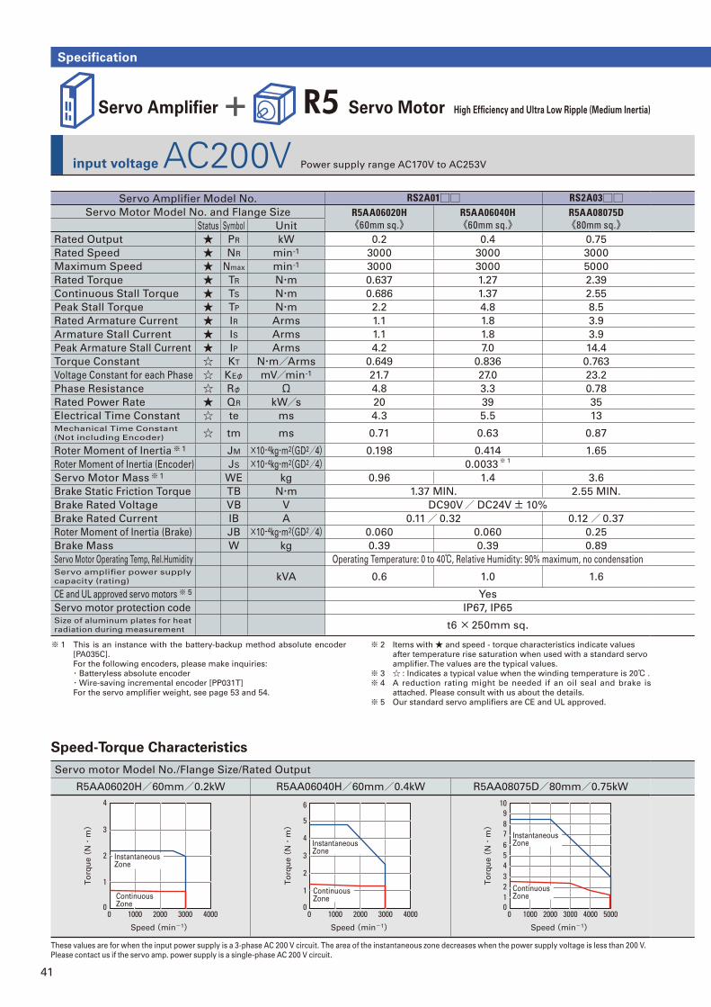
41
input voltage AC200V Power supply range AC170V to AC253V
Specification
Servo Amplifi er + R5 Servo Motor High Effi ciency and Ultra Low Ripple (Medium Inertia)
Servo Amplifi er Model No. RS2A01□□ RS2A03□□Servo Motor Model No. and Flange Size R5AA06020H
《60mm sq.》R5AA06040H《60mm sq.》
R5AA08075D《80mm sq.》Status Symbol Unit
Rated Output ★ PR kW 0.2 0.4 0.75
Rated Speed ★ NR min-1 3000 3000 3000
Maximum Speed ★ Nmax min-1 3000 3000 5000
Rated Torque ★ TR N・m 0.637 1.27 2.39
Continuous Stall Torque ★ TS N・m 0.686 1.37 2.55
Peak Stall Torque ★ TP N・m 2.2 4.8 8.5
Rated Armature Current ★ IR Arms 1.1 1.8 3.9
Armature Stall Current ★ IS Arms 1.1 1.8 3.9
Peak Armature Stall Current ★ IP Arms 4.2 7.0 14.4
Torque Constant ☆ KT N・m/Arms 0.649 0.836 0.763
Voltage Constant for each Phase ☆ KEφ mV/min-1 21.7 27.0 23.2
Phase Resistance ☆ Rφ Ω 4.8 3.3 0.78
Rated Power Rate ★ QR kW/s 20 39 35
Electrical Time Constant ☆ te ms 4.3 5.5 13 Mechanical Time Constant
(Not including Encoder) ☆ tm ms 0.71 0.63 0.87
Roter Moment of Inertia※ 1 JM ×10-4kg・m2(GD2/4) 0.198 0.414 1.65
Roter Moment of Inertia (Encoder) JS ×10-4kg・m2(GD2/4) 0.0033※ 1
Servo Motor Mass※ 1 WE kg 0.96 1.4 3.6
Brake Static Friction Torque TB N・m 1.37 MIN. 2.55 MIN.
Brake Rated Voltage VB V DC90V/ DC24V± 10%
Brake Rated Current IB A 0.11/ 0.32 0.12/ 0.37
Roter Moment of Inertia (Brake) JB ×10-4kg・m2(GD2/4) 0.060 0.060 0.25
Brake Mass W kg 0.39 0.39 0.89
Servo Motor Operating Temp, Rel.Humidity Operating Temperature: 0 to 40℃, Relative Humidity: 90% maximum, no condensationServo amplifi er power supply
capacity (rating) kVA 0.6 1.0 1.6
CE and UL approved servo motors※ 5 Yes
Servo motor protection code IP67, IP65Size of aluminum plates for heat
radiation during measurement t6 × 250mm sq.
※ 1 This is an instance with the battery-backup method absolute encoder
[PA035C].
For the following encoders, please make inquiries:
・Batteryless absolute encoder
・Wire-saving incremental encoder [PP031T]
For the servo amplifi er weight, see page 53 and 54.
※ 2 Items with ★ and speed - torque characteristics indicate values
after temperature rise saturation when used with a standard servo
amplifi er. The values are the typical values.
※ 3 ☆ : Indicates a typical value when the winding temperature is 20℃ .
※ 4 A reduction rating might be needed if an oil seal and brake is
attached. Please consult with us about the details.
※ 5 Our standard servo amplifi ers are CE and UL approved.
Servo motor Model No./Flange Size/Rated Output
R5AA06020H/60mm/0.2kW R5AA06040H/60mm/0.4kW R5AA08075D/80mm/0.75kW
0 300020001000 40000
1
3
2
4
Instantaneous Zone
Speed (min-1)
To
rqu
e (
N・
m)
Continuous Zone
0 300020001000 40000
1
6
5
4
3
2
Speed (min-1)
To
rqu
e (
N・
m)
Continuous Zone
Instantaneous Zone
0 2000 400030001000 500001
432
5
109876
Speed (min-1)
To
rqu
e (
N・
m)
Continuous Zone
Instantaneous Zone
These values are for when the input power supply is a 3-phase AC 200 V circuit. The area of the instantaneous zone decreases when the power supply voltage is less than 200 V.
Please contact us if the servo amp. power supply is a single-phase AC 200 V circuit.
Speed-Torque Characteristics
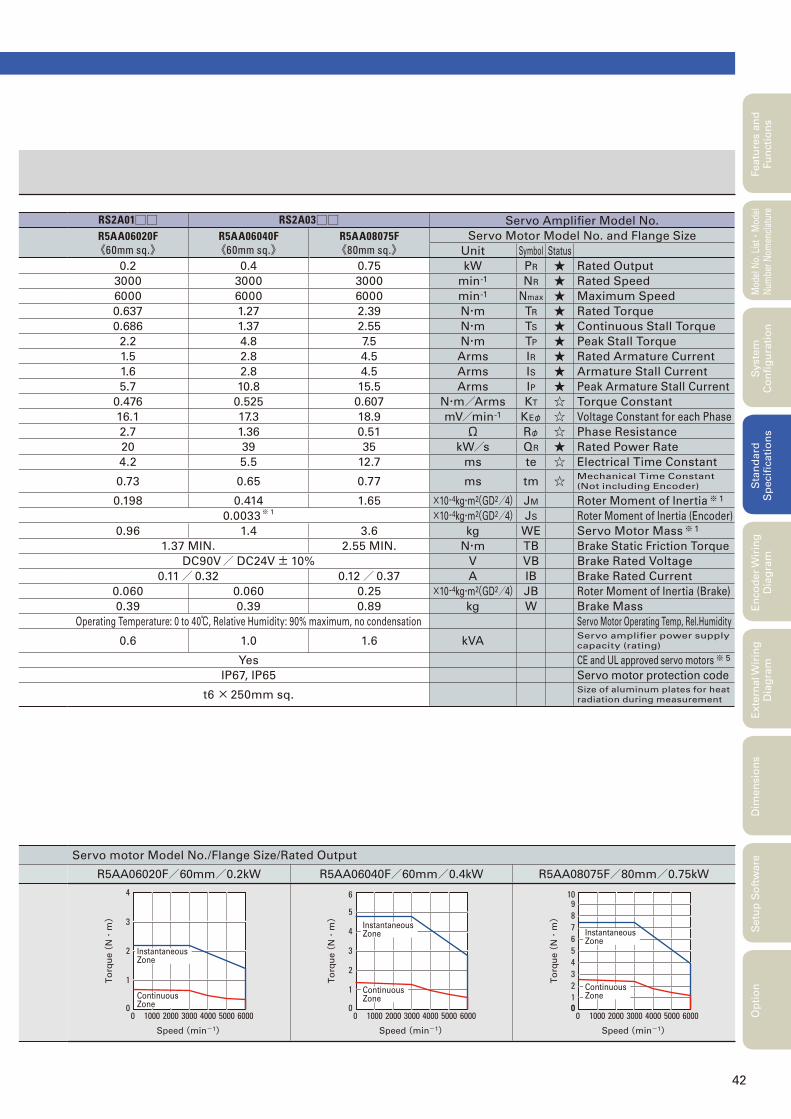
42
RS2A01□□ RS2A03□□ Servo Amplifi er Model No.
R5AA06020F《60mm sq.》
R5AA06040F《60mm sq.》
R5AA08075F《80mm sq.》
Servo Motor Model No. and Flange Size
Unit Symbol Status
0.2 0.4 0.75 kW PR ★ Rated Output
3000 3000 3000 min-1 NR ★ Rated Speed
6000 6000 6000 min-1 Nmax ★ Maximum Speed
0.637 1.27 2.39 N・m TR ★ Rated Torque
0.686 1.37 2.55 N・m TS ★ Continuous Stall Torque
2.2 4.8 7.5 N・m TP ★ Peak Stall Torque
1.5 2.8 4.5 Arms IR ★ Rated Armature Current
1.6 2.8 4.5 Arms IS ★ Armature Stall Current
5.7 10.8 15.5 Arms IP ★ Peak Armature Stall Current
0.476 0.525 0.607 N・m/Arms KT ☆ Torque Constant
16.1 17.3 18.9 mV/min-1 KEφ ☆ Voltage Constant for each Phase
2.7 1.36 0.51 Ω Rφ ☆ Phase Resistance
20 39 35 kW/s QR ★ Rated Power Rate
4.2 5.5 12.7 ms te ☆ Electrical Time Constant
0.73 0.65 0.77 ms tm ☆ Mechanical Time Constant
(Not including Encoder)
0.198 0.414 1.65 ×10⁻⁴kg・m2(GD2/4) JM Roter Moment of Inertia※ 1
0.0033※ 1 ×10⁻⁴kg・m2(GD2/4) JS Roter Moment of Inertia (Encoder)
0.96 1.4 3.6 kg WE Servo Motor Mass※ 1
1.37 MIN. 2.55 MIN. N・m TB Brake Static Friction Torque
DC90V/ DC24V± 10% V VB Brake Rated Voltage
0.11/ 0.32 0.12/ 0.37 A IB Brake Rated Current
0.060 0.060 0.25 ×10⁻⁴kg・m2(GD2/4) JB Roter Moment of Inertia (Brake)
0.39 0.39 0.89 kg W Brake Mass
Operating Temperature: 0 to 40℃, Relative Humidity: 90% maximum, no condensation Servo Motor Operating Temp, Rel.Humidity
0.6 1.0 1.6 kVAServo amplifi er power supply
capacity (rating)
Yes CE and UL approved servo motors※ 5
IP67, IP65 Servo motor protection code
t6 × 250mm sq.
Size of aluminum plates for heat
radiation during measurement
Servo motor Model No./Flange Size/Rated Output
R5AA06020F/60mm/0.2kW R5AA06040F/60mm/0.4kW R5AA08075F/80mm/0.75kW
10000 3000 500040002000 60000
1
3
2
4
Speed (min-1)
To
rqu
e (
N・
m)
Continuous Zone
Instantaneous Zone
0 300020001000 40000
1
6
5
4
3
2
5000 6000
Speed (min-1)
To
rqu
e (
N・
m)
Continuous Zone
Instantaneous Zone
00 3000 4000 500020001000 6000
01
109
45678
32
Speed (min-1)
To
rqu
e (
N・
m)
Continuous Zone
Instantaneous Zone
Featu
res a
nd
Fu
ncti
on
sM
odel
No.
Lis
t
・Mod
el
Num
ber
Nom
encl
atur
eS
tan
dard
S
pecifi
cati
on
sE
nco
der
Wir
ing
D
iag
ram
Exte
rnal W
irin
g
Dia
gra
mD
imen
sio
ns
Setu
p S
oft
ware
Op
tio
nS
yste
m
Co
nfi
gu
rati
on
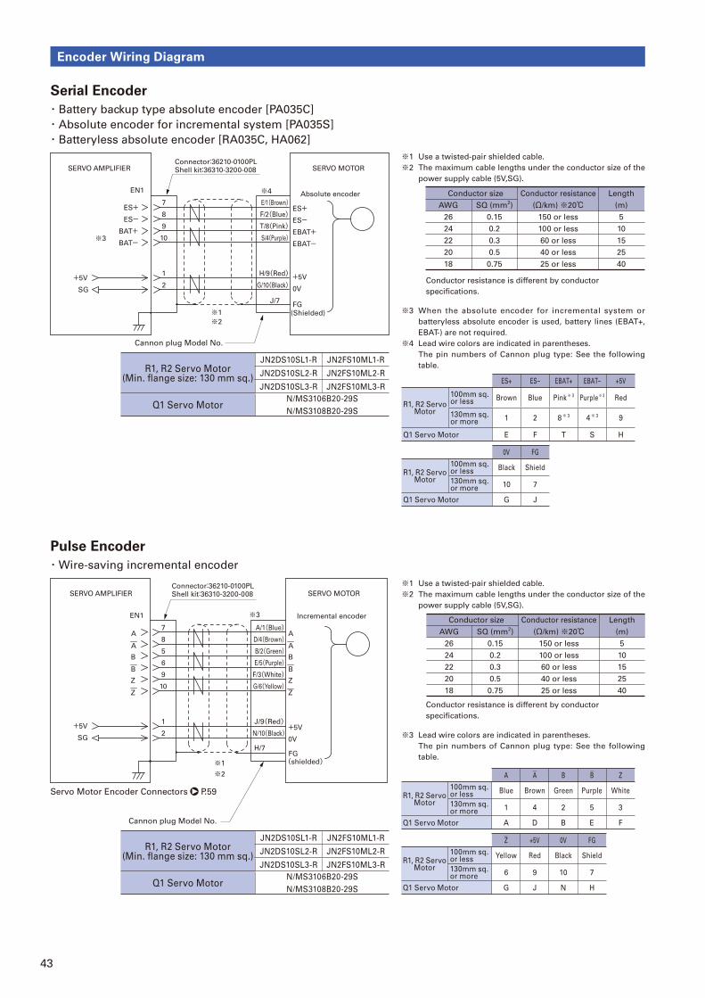
43
Encoder Wiring Diagram
Servo Motor Encoder Connectors P.59
Serial Encoder
・Battery backup type absolute encoder [PA035C]
・Absolute encoder for incremental system [PA035S]
・Batteryless absolute encoder [RA035C, HA062]
Pulse Encoder
・Wire-saving incremental encoder
※1 Use a twisted-pair shielded cable.
※2 The maximum cable lengths under the conductor size of the
power supply cable (5V,SG).
※1 Use a twisted-pair shielded cable.
※2 The maximum cable lengths under the conductor size of the
power supply cable (5V,SG).
※3 When the absolute encoder for incremental system or
batteryless absolute encoder is used, battery lines (EBAT+,
EBAT-) are not required.
※4 Lead wire colors are indicated in parentheses.
The pin numbers of Cannon plug type: See the following
table.
※3 Lead wire colors are indicated in parentheses.
The pin numbers of Cannon plug type: See the following
table.
Conductor resistance is different by conductor
specifi cations.
Conductor resistance is different by conductor
specifi cations.
※1
※4
2
1
8
7ES+ES-
+5V
SG
ES+ES-
+5V
0V
FG
E/1(Brown)F/2(Blue)
H/9(Red)G/10(Black)
J/7
(Shielded)
SERVO AMPLIFIER SERVO MOTOR
Absolute encoderEN1
Connector:36210-0100PLShell kit:36310-3200-008
BAT-BAT+
9
10 S/4(Purple)T/8(Pink)
EBAT-EBAT+
※2
※3
Cannon plug Model No.
AWG
26
24
22
20
18
SQ (mm2)
0.15
0.2
0.3
0.5
0.75
Conductor resistance
(Ω/km) ※20℃150 or less
100 or less
60 or less
40 or less
25 or less
Length
(m)
5
10
15
25
40
Conductor size
AWG
26
24
22
20
18
SQ (mm2)
0.15
0.2
0.3
0.5
0.75
Conductor resistance
(Ω/km) ※20℃150 or less
100 or less
60 or less
40 or less
25 or less
Length
(m)
5
10
15
25
40
Conductor size
※1
2
1
8
7A
A
+5V
SG
A
A
+5V
0V
A/1(Blue)
J/9(Red)N/10(Black)
H/7FG
SERVO AMPLIFIER SERVO MOTOR
EN1 Incremental encoder
5
6 E/5(Purple)
D/4(Brown)
9
10 G/6(Yellow)F/3(White)
B
B
Z
Z
B
B
Z
Z
B/2(Green)
(shielded)
※2
※3
Connector:36210-0100PLShell kit:36310-3200-008
Cannon plug Model No.
ES+ ES– EBAT+ EBAT– +5V
R1, R2 Servo Motor
100mm sq. or less Brown Blue Pink※ 3 Purple※ 3 Red
130mm sq. or more 1 2 8※ 3 4※ 3 9
Q1 Servo Motor E F T S H
0V FG
R1, R2 Servo Motor
100mm sq. or less Black Shield
130mm sq. or more 10 7
Q1 Servo Motor G J
A A B B Z
R1, R2 Servo Motor
100mm sq. or less Blue Brown Green Purple White
130mm sq. or more 1 4 2 5 3
Q1 Servo Motor A D B E F
Z +5V 0V FG
R1, R2 Servo Motor
100mm sq. or less Yellow Red Black Shield
130mm sq. or more 6 9 10 7
Q1 Servo Motor G J N H
R1, R2 Servo Motor(Min. fl ange size: 130 mm sq.)
JN2DS10SL1-R JN2FS10ML1-R
JN2DS10SL2-R JN2FS10ML2-R
JN2DS10SL3-R JN2FS10ML3-R
Q1 Servo MotorN/MS3106B20-29S
N/MS3108B20-29S
R1, R2 Servo Motor(Min. fl ange size: 130 mm sq.)
JN2DS10SL1-R JN2FS10ML1-R
JN2DS10SL2-R JN2FS10ML2-R
JN2DS10SL3-R JN2FS10ML3-R
Q1 Servo MotorN/MS3106B20-29S
N/MS3108B20-29S
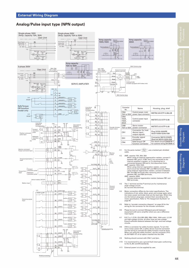
44
External Wiring Diagram
Analog/Pulse input type (NPN output)
Featu
res a
nd
Fu
ncti
on
sM
odel
No.
Lis
t
・Mod
el
Num
ber
Nom
encl
atur
eS
tan
dard
S
pecifi
cati
on
sE
nco
der
Wir
ing
D
iag
ram
Exte
rnal W
irin
g
Dia
gra
mD
imen
sio
ns
Setu
p S
oft
ware
Op
tio
nS
yste
m
Co
nfi
gu
rati
on
DC12Vto 24V
DC5V,
3-phase 200V
MC
System error
MC
CN1
MC
S
R
r
T
t
SG
17
18
SG
SG
SG
SG
SG
19
F-PC
F-PC
SG
R-PC
R-PC
SG
+5V
+5V+5V
+5V
SG
SG
U
W
V
EN1
RY1
90V(24V)
26
27
47
28
29
48
/T-REF
SG20
21-
+
V-REF
SG
SG
SG
+
-
23
22
SG
SG
T-COMP
F-TLA
SG
R-TLA
SGBTP-I
BTN-I
1
2
CONT-COM
CONT1DC5V to 24V
50
37
36 CONT2
35 CONT3
34 CONT4
33 CONT5
32 CONT6
SG38
16
15
CONT8
SG
CONT8
SG SG
SG
13
14
CONT7
CONT7
+5V +5V
SG
+5V +5V
OUT-COM
OUT-COM
46OUT8
OUT7 45
44OUT6
43OUT5
42OUT4
41OUT3
40OUT2
39OUT1
49OUT-PWR
SG
31SG
30MON1
SG
11
12
ZOP
SG
SG
10PS
9PS
8
7
ZO
ZO
6BO
5BO
4
3
AO
AO
24
25
※4
※6
※11
※11
※6
SH SH
SH
SH
※51
2
4
3
6
5
8
NC
NC
HWGOFF1-
HWGOFF1+
HWGOFF2-
HWGOFF2+
7 EDM-
EDM+
CN4
DC24V
DC24V
※9
※11
※11
※8
CNA
SERVO AMPLIFIER
※10
Single-phase 200V (Amp. capacity 15A to 50A)
MCMC
MC
User Unit
※10
RB
2
P RB
1
+
-
Amp.capacity100A,150A
Amp.capacity300A
RB
1
-
+
RB
2
RB
4
※2
※3
※2
※3
Amp.capacity
15A to 50A
ONStart ready
OFFStart ready
MC
User Unit
System error
MCMC
Emergency stop
Power Supply Single-phase
100 to 115V
50/60Hz
Single-phase 100V (Amp. capacity 15A, 30A)
Forward revolution pulse
Backward revolution pulse
SERVO MOTOR
Red
(Green/Yellow)
White
Black
Green Holding brake(models equipped with brakes only)
Orange (Yellow)
Orange (Yellow)
Encoder
Forward revolution pulse
Backward revolution pulse
Lithium battery DC3.6V
Line receiverHD26C32 Corresponding
50A: CNB100 to 300A: Terminalblock
50A: CNA 100 to 300A:
Terminalblock
Line driverHD26C31 Corresponding
Line driverHD26C31 Corresponding
Line receiverHD26C32 Corresponding
Position command pulse input
Velocity command / Torque command input
Torquecompensation input
Torque limit input
Battery input
General-purpose input
Shield processing
General-purpose output
Monitor output
Encoder divisionsignal output
CNA100A,150A,300A
Control power input connector
NameConnector
No.
CN1
EN1
Connector for host device input / output signals
Encoder signal connector
Housing, plug, shell
Shield processing
MSTBT2.5/2-STF-5.08
CNB15A to 50A
Servo motor power connector
MSTBT2.5/3-STF-5.08
CNA15A to 50A
Control power, main power input connector
MSTB2.5/8-STF-5.08LUB
Plug:10150-3000PEShell:10350-52A0-008
CN4 Safe Torque Off function connector
For short-circuit:2040978-1For customer wining:2013595-3
Connector:36210-0100PLShell kit:36310-3200-008
200 to 230V
50/60Hz
System error
Start ready
OFFStart ready
ON
Power Supply
3-phase
200 to 230V
50/60HzTerminalblock
External regeneration resistor
External regeneration resistor
Terminalblock
Built in regeneration resistor
With Cannon plug
With Cannon plug
Emergency stop
Start ready
OFFStart ready
ON
Emergency stop
User Unit
Power Supply
Single-phase
Safe Torque Off function model only
RB
1
+
※3
RB
2
※2
CN
A
※10
Built in regeneration resistor
※1 For the parts marked ,use a twisted pair shielded cable.
※2 AMP. capacity 15A, 30A, 50A When using an external regeneration resistor, connect it
between RB1 and 2. If RB1 and 2 are connected to the internal amplifier's resistor, or if a shorting bar is connected between RB1and 4, first disconnect them.
AMP. capacity 100A,150A When using internal regeneration resistor, connect
short-circuit bar between RB1 and RB4 terminals. When using external regeneration resistor, connect it between RB1 and RB2 terminals after removing short-circuit bar between RB1 and RB4 terminals.
AMP. capacity 300A Connect external regeneration resistor between RB1 and
RB2 terminals.
※3 The -○ terminal and the P terminal are for maintenance (high-voltage circuit).
Do not wire this terminal.
※4 Motor connection differs by the motor specifications. The indications of red, white, black, green and orange apply when the motor power and brake lines are the lead type. When they are the Cannon plug type, connect them according to the motor specification. Refer to "Pin Assignment Symbols" on page 60.
※5 Refer to "encoder connection diagram" on page 43 for the wiring for the connector for the encoder connection.
※6 Please be sure to connect SG(signal ground) between equipment with servo amplifier when you use a difference input signal.
※7 R,S,T,t,r,-○,P,DL1,DL2,RB1,RB2, RB4 (100A, 150A only), U,V,W are high-voltage circuits, all other lines are low-voltage. Ensure sufficient distance between the high- and low-voltage circuits.
※8 CN4 is a connector for safety function signals. To turn the servo motor power ON, a safety device must be connected and the wiring to activate the safety function must be done. When not using the safety function, use the connector (P.N : AL-00718251-01) of an option inserted into the CN4.
※9 Nothing should connect with CN4-1 and 2pin.
※10 It is recommend to use a ground fault interrupter conforming to the UL,IEC and EN standards.
※11 External power is to be supplied by user.
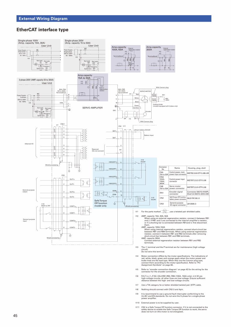
45
External Wiring Diagram
EtherCAT interface type
CN0/1
S
R
r
T
t
U
W
V
EN1
RY1
90V(24V)
1
2
OUT1+
OUT1-
CONT1+
CONT1-
※4
SH SH
CNA
※5
4
5
8
7
6
3
CN3
CONT2-
CONT2+
SH
1
2
3
4
BAT+
BAT-
SH
※11
DC5V to 24V
※10
CN2
OUT2-
OUT2+
SH
1
2
3
4
5
6
7
8
※7
※8
3-phase 200V (AMP. capacity 50 to 300A)
MCMC
MC
User Unit
※9
Single-phase 200V (Amp. capacity 15 to 50A)
MCMC
MC
User Unit
※9
RB
2
P RB
1
+
-
Amp.capacity100A,150A
Amp.capacity300A
RB
1
-
+
RB
2
RB
4
※2
※3
※2
※3
Amp.capacity
15A to 50A
RB
1
+
※3
RB
2
※2
CN
A
Single-phase 100V (Amp. capacity 15A, 30A)
MC
User Unit
MCMC
100 to 115V
50/60Hz
ONStart ready
OFFStart ready
System error
Emergency stop
Power Supply Single-phase
SERVO MOTOR
Encoder
NameConnector
No.
Safe Torque Off function, battery power connector
Housing, plug, shell
Encoder signal connector
Connector:36210-0100PLShell kit:36310-3200-008
MUF-PK10K-X
General-purpose I/O signal connector
2013595-3
Battery input
Lithium battery DC3.6V
CN2
EN1
CN3
Ethernet I/O
General-purpose output
General-purpose input
Reserved(Do not connect)
Power Supply
3-phase
200 to 230V
50/60Hz
200 to 230V
50/60Hz
External regeneration resistor
External regeneration resistor
Terminalblock Terminalblock
Built in regenerationresistor
With Cannon plug
With Cannon plug
Shield processing
CNA100A,150A,300A
Control power input connector
MSTBT2.5/2-STF-5.08
CNB15A to 50A
Servo motor power connector
MSTBT2.5/3-STF-5.08
CNA15A to 50A
Control power, main power input connector
MSTB2.5/8-STF-5.08LUB
Red
(Green/Yellow)
White
Black
GreenHolding brake(models equipped with brakes only)
Orange (Yellow)
Orange (Yellow)
50A: CNB100~300A: Terminalblock
50A: CNA100 to 300A:
Terminalblock
SERVO AMPLIFIER
Power Supply
Single-phase
Built in regenerationresistor
System error
Start ready
OFFStart ready
ON
Emergency stop
System error
Start ready
OFFStart ready
ON
Emergency stop
Shield processing
Shield processing
※9
Safe Torque Off function model only
※1 For the parts marked ,use a twisted pair shielded cable.
※2 AMP. capacity 15A, 30A, 50A When using an external regeneration resistor, connect it between RB1
and 2. If RB1 and 2 are connected to the internal amplifier's resistor, or if a shorting bar is connected between RB1and 4, first disconnect them.
AMP. capacity 100A,150A When using internal regeneration resistor, connect short-circuit bar
between RB1 and RB4 terminals. When using external regeneration resistor, connect it between RB1 and RB2 terminals after removing short-circuit bar between RB1 and RB4 terminals.
AMP. capacity 300A Connect external regeneration resistor between RB1 and RB2
terminals.
※3 The -○ terminal and the P terminal are for maintenance (high voltage circuit).Do not wire this terminal.
※4 Motor connection differs by the motor specifications. The indications of red, white, black, green and orange apply when the motor power and brake lines are the lead type. When they are the Cannon plug type, connect them according to the motor specification. Refer to "Pin Assignment Symbols" on page 60.
※5 Refer to "encoder connection diagram" on page 43 for the wiring for the connector for the encoder connection.
※6 R,S,T,t,r,-○,,P,DL1,DL2,RB1,RB2, RB4 (100A, 150A only), U,V,W are high-voltage circuits, all other lines are low-voltage. Ensure sufficient distance between the high- and low-voltage circuits.
※7 Use a TIA category 5e or better shielded twisted pair (STP) cable.
※8 Nothing should connect with CN2-3 and 4pin.
※9 It is recommend to use a ground fault interrupter conforming to the UL,IEC and EN standards. Do not wire the S phase for a single-phase power amplifier.
※10 External power is to be supplied by user.
※11 CN2 is a Safe Torque Off function connector. If it is not connected to the safety device to enable the Safe Torque Off function to work, the servo does not turn on (the motor is not energized).
※10
DC24V
※10
DC24V
7
8
9
10
6
5HWGOFF1+
EDM+
HWGOFF1-
HWGOFF2-
HWGOFF2+
EDM-
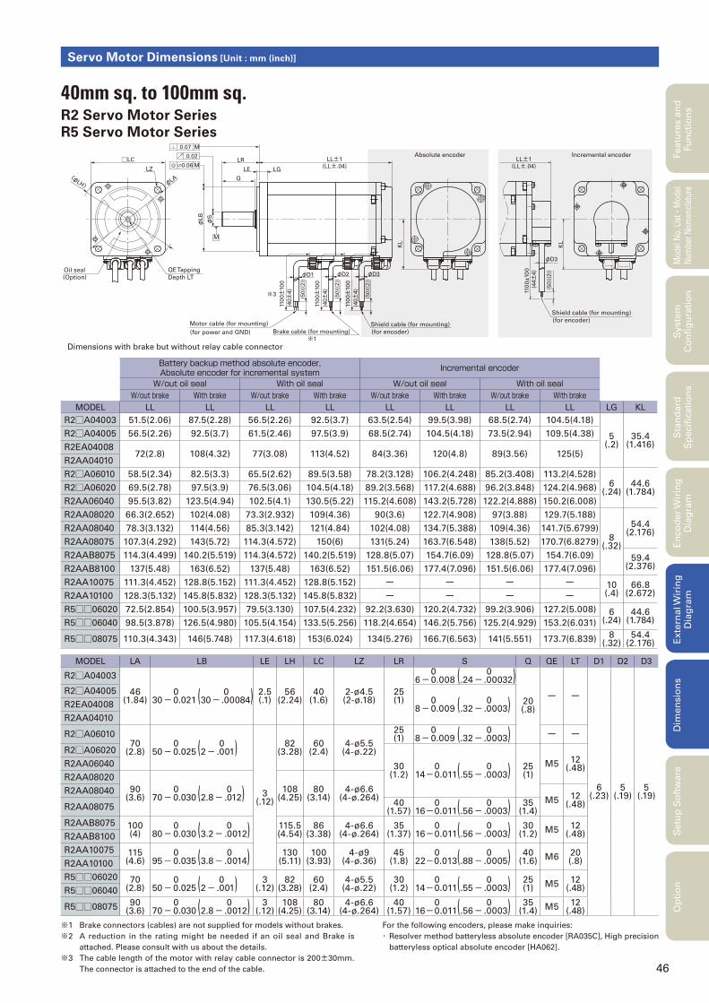
46
Servo Motor Dimensions [Unit : mm (inch)]
(50)(
(2))
110
0±
10
0
φD3
KL
Absolute encoder Incremental encoder
(for power and GND)
Motor cable (for mounting)
Brake cable (for mounting)
※1
※3
(for encoder)
Shield cable (for mounting)(for encoder)
Shield cable (for mounting)
(50)(
(2))
(50)(
(2))
0.06
0.07
0.02
M
M
φS
φLB
Q
LR
LE LG
LL±1
(LL±.04)
LL±1
(LL±.04)
φD2φD1 φD3
□LC
LZ
(Option)
Oil seal
Depth LT
QE Tapping
KL
110
0±10
0
(40±
4) (4
4±4)
(40±
4)
(50)(
(2))
(40±
4)
110
0±10
0
110
0±10
0
M
φLA(φ
LH)
Dimensions with brake but without relay cable connector
※1 Brake connectors (cables) are not supplied for models without brakes.
※2 A reduction in the rating might be needed if an oil seal and Brake is
attached. Please consult with us about the details.
※3 The cable length of the motor with relay cable connector is 200±30mm.
The connector is attached to the end of the cable.
For the following encoders, please make inquiries:
・ Resolver method batteryless absolute encoder [RA035C], High precision
batteryless optical absolute encoder [HA062].
Battery backup method absolute encoder,Absolute encoder for incremental system Incremental encoder
W/out oil seal With oil seal W/out oil seal With oil sealW/out brake With brake W/out brake With brake W/out brake With brake W/out brake With brake
MODEL LL LL LL LL LL LL LL LL LG KL
R2□A04003 51.5(2.06) 87.5(2.28) 56.5(2.26) 92.5(3.7) 63.5(2.54) 99.5(3.98) 68.5(2.74) 104.5(4.18)
5(.2)
35.4(1.416)
R2□A04005 56.5(2.26) 92.5(3.7) 61.5(2.46) 97.5(3.9) 68.5(2.74) 104.5(4.18) 73.5(2.94) 109.5(4.38)
R2EA0400872(2.8) 108(4.32) 77(3.08) 113(4.52) 84(3.36) 120(4.8) 89(3.56) 125(5)
R2AA04010
R2□A06010 58.5(2.34) 82.5(3.3) 65.5(2.62) 89.5(3.58) 78.2(3.128) 106.2(4.248) 85.2(3.408) 113.2(4.528)6
(.24)44.6
(1.784)R2□A06020 69.5(2.78) 97.5(3.9) 76.5(3.06) 104.5(4.18) 89.2(3.568) 117.2(4.688) 96.2(3.848) 124.2(4.968)
R2AA06040 95.5(3.82) 123.5(4.94) 102.5(4.1) 130.5(5.22) 115.2(4.608) 143.2(5.728) 122.2(4.888) 150.2(6.008)
R2AA08020 66.3(2.652) 102(4.08) 73.3(2.932) 109(4.36) 90(3.6) 122.7(4.908) 97(3.88) 129.7(5.188)
8(.32)
54.4(2.176)R2AA08040 78.3(3.132) 114(4.56) 85.3(3.142) 121(4.84) 102(4.08) 134.7(5.388) 109(4.36) 141.7(5.6799)
R2AA08075 107.3(4.292) 143(5.72) 114.3(4.572) 150(6) 131(5.24) 163.7(6.548) 138(5.52) 170.7(6.8279)
R2AAB8075 114.3(4.499) 140.2(5.519) 114.3(4.572) 140.2(5.519) 128.8(5.07) 154.7(6.09) 128.8(5.07) 154.7(6.09) 59.4(2.376)R2AAB8100 137(5.48) 163(6.52) 137(5.48) 163(6.52) 151.5(6.06) 177.4(7.096) 151.5(6.06) 177.4(7.096)
R2AA10075 111.3(4.452) 128.8(5.152) 111.3(4.452) 128.8(5.152) ー ー ー ー 10(.4)
66.8(2.672)R2AA10100 128.3(5.132) 145.8(5.832) 128.3(5.132) 145.8(5.832) ー ー ー ー
R5□□06020 72.5(2.854) 100.5(3.957) 79.5(3.130) 107.5(4.232) 92.2(3.630) 120.2(4.732) 99.2(3.906) 127.2(5.008) 6(.24)
44.6(1.784)R5□□06040 98.5(3.878) 126.5(4.980) 105.5(4.154) 133.5(5.256) 118.2(4.654) 146.2(5.756) 125.2(4.929) 153.2(6.031)
R5□□08075 110.3(4.343) 146(5.748) 117.3(4.618) 153(6.024) 134(5.276) 166.7(6.563) 141(5.551) 173.7(6.839) 8(.32)
54.4(2.176)
MODEL LA LB LE LH LC LZ LR S Q QE LT D1 D2 D3
R2□A04003
46(1.84)
030-0.021
0(30- .00084) 2.5(.1)
56(2.24)
40(1.6)
2-ø4.5(2-ø.18)
25(1)
06-0.008
0(.24- .00032)
20(.8)
ー ー
6(.23)
5(.19)
5(.19)
R2□A04005 08-0.009
0(.32- .0003)R2EA04008
R2AA04010
R2□A0601070
(2.8) 050-0.025
0(2- .001)
3(.12)
82(3.28)
60(2.4)
4-ø5.5(4-ø.22)
25(1)
08-0.009
0(.32- .0003) ー ー
R2□A06020
30(1.2)
014-0.011
0(.55- .0003) 25(1)
M5 12(.48)R2AA06040
R2AA08020
90(3.6)
070-0.030
0(2.8- .012) 108(4.25)
80(3.14)
4-ø6.6(4-ø.264)
R2AA08040M5 12
(.48)R2AA08075 40(1.57)
016-0.011
0(.56- .0003) 35(1.4)
R2AAB8075 100(4)
080-0.030
0(3.2- .0012) 115.5(4.54)
86(3.38)
4-ø6.6(4-ø.264)
35(1.37)
016-0.011
0(.56- .0003) 30(1.2) M5 12
(.48)R2AAB8100
R2AA10075 115(4.6)
095-0.035
0(3.8- .0014) 130(5.11)
100(3.93)
4-ø9(4-ø.36)
45(1.8)
022-0.013
0(.88- .0005) 40(1.6) M6 20
(.8)R2AA10100
R5□□06020 70(2.8)
050-0.025
0(2- .001) 3(.12)
82(3.28)
60(2.4)
4-ø5.5(4-ø.22)
30(1.2)
014-0.011
0(.55- .0003) 25(1) M5 12
(.48)R5□□06040
R5□□08075 90(3.6)
070-0.030
0(2.8- .0012) 3(.12)
108(4.25)
80(3.14)
4-ø6.6(4-ø.264)
40(1.57)
016-0.011
0(.56- .0003) 35(1.4) M5 12
(.48)
Featu
res a
nd
Fu
ncti
on
sM
odel
No.
Lis
t
・Mod
el
Num
ber
Nom
encl
atur
eS
tan
dard
S
pecifi
cati
on
sE
nco
der
Wir
ing
D
iag
ram
Exte
rnal W
irin
g
Dia
gra
mD
imen
sio
ns
Setu
p S
oft
ware
Op
tio
nS
yste
m
Co
nfi
gu
rati
on
40mm sq. to 100mm sq.R2 Servo Motor Series
R5 Servo Motor Series
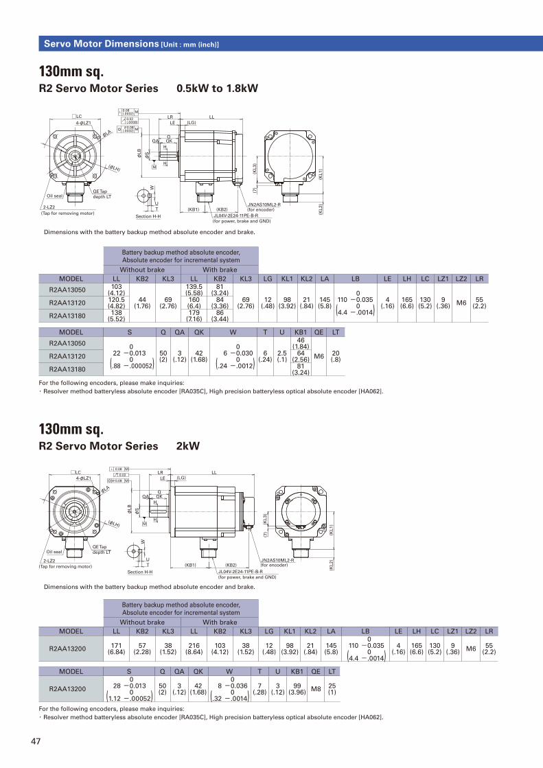
47
Servo Motor Dimensions [Unit : mm (inch)]
Dimensions with the battery backup method absolute encoder and brake.
Dimensions with the battery backup method absolute encoder and brake.
For the following encoders, please make inquiries:
・ Resolver method batteryless absolute encoder [RA035C], High precision batteryless optical absolute encoder [HA062].
For the following encoders, please make inquiries:
・ Resolver method batteryless absolute encoder [RA035C], High precision batteryless optical absolute encoder [HA062].
4-φLZ1
2-LZ2
QE Tap
depth LT
MH
0.02(.0008)
0.08(.0032) M
0.08(.0032)
M
H
JL04V-2E24-11PE-B-R
(for power, brake and GND)
JN2AS10ML2-R(for encoder)
Oil seal
(Tap for removing motor)Section H-H
QA
W
(φLH)
□LC
φLA
φLB
φS
T (KB1)
U
(KB2)
(7)
(KL3)
QKQ
LE (LG)
LR LL
(KL2)
(KL1)
Battery backup method absolute encoder,
Absolute encoder for incremental system
Without brake With brake
MODEL LL KB2 KL3 LL KB2 KL3 LG KL1 KL2 LA LB LE LH LC LZ1 LZ2 LR
R2AA13050103
(4.12)44
(1.76)69
(2.76)
139.5(5.58)
81(3.24)
69(2.76)
12(.48)
98(3.92)
21(.84)
145(5.8)
110
(4.4
0-0.035 0-.0014)
4(.16)
165(6.6)
130(5.2)
9(.36)
M655
(2.2)R2AA13120
120.5(4.82)
160(6.4)
84(3.36)
R2AA13180138
(5.52)179
(7.16)86
(3.44)
MODEL S Q QA QK W T U KB1 QE LT
R2AA13050
22
(.88
0-0.013 0-.000052)
50(2)
3(.12)
42(1.68)
6
(.24
0-0.030 0-.0012)
6(.24)
2.5(.1)
46(1.84)
M620(.8)
R2AA1312064
(2.56)
R2AA1318081
(3.24)
130mm sq.R2 Servo Motor Series 0.5kW to 1.8kW
130mm sq.R2 Servo Motor Series 2kW
Battery backup method absolute encoder,
Absolute encoder for incremental system
Without brake With brake
MODEL LL KB2 KL3 LL KB2 KL3 LG KL1 KL2 LA LB LE LH LC LZ1 LZ2 LR
R2AA13200171
(6.84)57
(2.28)38
(1.52)216
(8.64)103
(4.12)38
(1.52)12
(.48)98
(3.92)21
(.84)145(5.8)
110
(4.4
0-0.035 0-.0014)
4(.16)
165(6.6)
130(5.2)
9(.36)
M655
(2.2)
MODEL S Q QA QK W T U KB1 QE LT
R2AA1320028
(1.12
0-0.013 0-.00052)
50(2)
3(.12)
42(1.68)
8
(.32
0-0.036 0-.0014)
7(.28)
3(.12)
99(3.96)
M825(1)
JL04V-2E24-11PE-B-R
(for power, brake and GND)
(Tap for removing motor)
2-LZ2T
Section H-H
(KB1) (KB2)
U
M(φLH)
W
φLA
φLB
φS
QA
4-φLZ1
□LC0.02
0.08
0.08
M
M
H
H
QQK
LR
LE (LG)
LL
(for encoder)
(KL1)
(KL2)JN2AS10ML2-R
(KL3)
(7)
QE Tap
depth LTOil seal
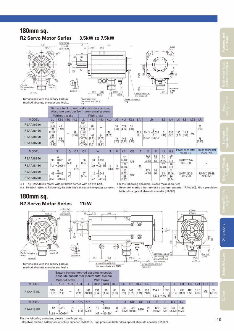
48
Featu
res a
nd
Fu
ncti
on
sM
odel
No.
Lis
t
・Mod
el
Num
ber
Nom
encl
atur
eS
tan
dard
S
pecifi
cati
on
sE
nco
der
Wir
ing
D
iag
ram
Exte
rnal W
irin
g
Dia
gra
mD
imen
sio
ns
Setu
p S
oft
ware
Op
tio
nS
yste
m
Co
nfi
gu
rati
on
180mm sq.R2 Servo Motor Series 3.5kW to 7.5kW
180mm sq.R2 Servo Motor Series 11kW
Battery backup method absolute encoder,
Absolute encoder for incremental system
Without brake With brake
MODEL LL KB2 KB3 KL3 LL KB2 KB3 KL3 LG KL1 KL2 LA LB LE LH LC LZ1 LZ2 LR
R2AA1811K395
(15.55)60
(2.4)ー 81
(3.19)467
(18.39)133
(5.24)90
(3.54)81
(3.19)19
(.76)143
(5.63)23
(0.91)200
(7.87)114.3
(4.572
0-0.035 0-.0014)
3(.12)
230(9.2)
180(7.2)
13.5(.54)
M879
(3.16)
MODEL S Q QA QK W T U KB1 QE LT IE IF IL1 IL2
R2AA1811K42
(1.68
0-0.016 0-.00064)
75(3)
3(12)
67(2.64)
12
(.47
0-0.043 0-.00169)
8(.31)
3(.12)
220(8.66)
M1025(1)
123(4.92)
50(2)
63(2.52)
108(4.25)
Battery backup method absolute encoder,
Absolute encoder for incremental system
Without brake With brake
MODEL LL KB2 KB3 KL3 LL KB2 KB3 KL3 LG KL1 KL2 LA LB LE LH LC LZ1 LZ2 LR
R2AA18350155(6.2) 48
(1.92)
ー 38(1.52)
205(8.07) 98
(3.86)ー
38(1.52)
16(.64)
123(4.92)
21(.84)
200(8)
114.3
(4.572
0-0.035 0-.0014)
3(.12)
230(9.2)
180(7.2)
13.5(.54)
M8
65(2.6)
R2AA18450172
(6.88)222
(8.74)
R2AA18550228
(9.12) 59(2.36)
274(10.79)
107(4.21)
64(2.52) 19
(.76)144
(5.76)22
(.88)79
(3.16)R2AA18750
273(10.92)
329(12.95)
117(4.61)
74(2.91)
MODEL S Q QA QK W T U KB1 QE LT IE IF IL1 IL2Power connector
model No.Brake connector
model No.
R2AA1835035
(1.4
0-0.016 0-.00064)
60(2.4)
3(.12)
50(1.97)
10
(.39
0-0.036 0-.00141) 8
(.32)3
(.12)
92(3.68)
M8
25(1)
123※ 1
(4.92)
50※ 1
(2)
47※ 1
(1.85)
20※ 1
(.8) JL04V-2E24-11PE-B-R
ー※ 2
R2AA18450109
(4.36)
123(4.92)
50(2)
57(2.28)
20(.8)
R2AA1855042
(1.68
0-0.016 0-.00064)
75(3)
67(2.64)
12
(.47
0-0.043 0-.00169)
153(6.12)
M1063
(2.52)
41(1.64) JL04V-2E32-
17PE-B-RJL04V-2E10SL-
3PE-B-RR2AA18750
198(7.92)
86(3.44)
(φLH
)
φLA
Depth LT(Tap for removing
motor)
2-LZ2 QE Tap
4-φLZ1
□LCM
M0.08
0.08
0.022-M8
2-M8Eye Bolt
(IE
)
LL
(KB2)
(IL1)
(KB1)
(IL2) (KB3)
(for power and GND)
Power connector
(KL1)
(KL2)
Brake connector
(for encoder)
JN2AS10ML2-R(IF)
(7)
(KL3)
(LG) (IL2)
※1
※1
※2※2
Oil seal
M
φLB
φS
Q
LR
UT
W
H
H
Section H-H
QA QK
LE
φLA
(φLH
)
depth LT
2-LZ2
(Tap for removing
motor)
QE Tap
□LC
4-φLZ1M
M
0.08
0.10
0.03
(101)
(IE
)(KL3)
(KL1)
(KL2)
JL04V-2E32-17PE-B-R
(KB1)
(IL1) (IL2)
(for encoder)
JL04V-2E10SL-3PE-B-R
(21)
(KB3)
(KB2)
Exhaust
JN2AS10ML2-R
(for cooling fan)
MS3102A10SL-4P
(40)
(IF)
(7)
(15)
Eye bolt
2-M8
LL
(LG) (IL2)
Exhaust
Intake
(□145)
(□195)
(for brake)(for power, brake and GND)
Oil seal
M
φS
φLB
LE
LR
Q
H
H
T
Section H-H
W
U
QA QK
※1 The R2AA18350 motor without brake comes with no eye bolt.
※2 For R2AA18350 and R2AA18450, the brake line is shared with the power connector.
For the following encoders, please make inquiries:
・ Resolver method batteryless absolute encoder [RA035C], High precision
batteryless optical absolute encoder [HA062].
For the following encoders, please make inquiries:
・ Resolver method batteryless absolute encoder [RA035C], High precision batteryless optical absolute encoder [HA062].
Dimensions with the battery backup
method absolute encoder and brake.
Dimensions with the battery backup
method absolute encoder and brake.

49
Servo Motor Dimensions [Unit : mm (inch)]
220mm sq.R2 Servo Motor Series 5kW
□LC LL
(KB1) (KB2)
LR
QA QKφ
S
φLB
(KL3)
7
(KL1)
(KL2)
(φLH)
φLA
Oil seal
4-LZ2
(Tap for removing motor)
QE Tap
depth LT
LE (LG)
Section H-H
W
UT
(IL2)
(IL1) (IL2) (IF)
(IF)
H
H
M
0.08
0.08
0.02
M
M
4-φLZ1
(IE
)
Eye bolt2-M8
(for power, brake and GND)JL04V-2E24-11PE-B-R JN2AS10ML2-R
(for encoder)
Q
2-M8
Eye bolt
Dimensions with the battery backup method absolute encoder and brake.
Battery backup method absolute encoder,
Absolute encoder for incremental systemIncremental encoder
Without brake With brake Without brake With brake
MODEL LL KB2 KL3 LL KB2 KL3 LL KB2 KL3 LL KB2 KL3 LG KL1 KL2 KL3 LA LB LE LH
R2AA22500163
(6.52)52
(2.08)38
(1.52)216
(8.64)106
(4.24)38
(1.52)177
(7.08)59
(2.36)65
(2.6)230(9.2)
113(4.52)
65(2.6)
16(.64)
142(5.68)
21(.84)
38(1.52)
235(9.4)
200
(8
0-0.046 0-.00184)
4(.16)
270(10.8)
MODEL LC LZ1 LZ2 LR S Q QA QK W T U KB1 QE LT IE IF IL1 IL2
R2AA22500220(8.8)
13.5(.54)
M1265
(2.6)35
(1.4
0-0.016 0-.00064)
60(2.4)
3(.12)
50(2)
10
(.4
0-0.036 0-.00143)
8(.32)
3(.12)
96(3.84)
M825(1)
142(5.68)
60(2.4)
48(1.92)
35(1.4)
For the following encoders, please make inquiries:
・ Resolver method batteryless absolute encoder [RA035C], High precision batteryless optical absolute encoder [HA062].
R2 Servo Motor Series 7kW to 15kW
Battery backup method absolute encoder,
Absolute encoder for incremental system
Without brake With brake
MODEL LL KB2 KB3 KL3 LL KB2 KB3 KL3 LG KL1 KL2 LA LB LE LH LC LZ1 LZ2 LR S
R2AA22700265
(10.43)54
(2.13)
ー 38(1.50)
325(12.80)
114(4.49)
59(2.32)
38(1.50)
19(0.75)
141(5.55)
21(.83)
235(9.25)
200
(7.87
0-0.046 0-.00181)
4(.16)
270(10.63)
220(8.66)
13.5(.53)
M1079
(3.11)55
(2.16
0-0.019 0-.00074)
R2AA2211K304
(11.97) 63(2.48)
364(14.33) 123
(4.92)68
(2.68)162(6.8)
22(.87)
R2AA2215K343
(13.50)403
(15.87)
MODEL Q QA QK W T U KB1 QE LT IE IF IL1 IL2
R2AA22700
75(2.95)
3(.12)
67(2.64)
16
(.63
0-0.043 0-.00169)
10(.39)
4(.16)
196(7.72)
M1025
(.98)142
(5.59)60
(2.36)69
(2.72)
62(2.44)
R2AA2211K226
(8.90)101
(3.98)
R2AA2215K265
(10.43)140(5.51)
For the following encoders, please make inquiries:
・ Resolver method batteryless absolute encoder [RA035C], High precision batteryless optical absolute encoder [HA062].
TU
W
QA
φS
φLB
Oil seal
(Tap for removing motor)
2-LZ2
QE Tap
depth LT
M
4-φLZ1
□LC 0.03
0.08 M
0.1 M
(KL1)
(KL2)
JN2AS10ML2-R
(for encoder)
QK
(IL2)
(KB1)
JL04V-2E32-17PE-B-R
(IL1)
(for power and GND)
Q
H
(KB3)
LL
(IL2)
LR
(LG)
H
LE
2-M8
Eye bolt
(IF)
2-M8
For Eye bolt
(IF)
φLA
(φLH
)
Section H-HJL04V-2E10SL-3PE-B-R
(for brake)
(KB2)
(KL3)
(7)
(IE
)
Dimensions with the battery backup method absolute encoder and brake.
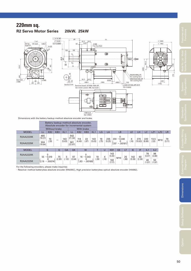
50
Featu
res a
nd
Fu
ncti
on
sM
odel
No.
Lis
t
・Mod
el
Num
ber
Nom
encl
atur
eS
tan
dard
S
pecifi
cati
on
sE
nco
der
Wir
ing
D
iag
ram
Exte
rnal W
irin
g
Dia
gra
mD
imen
sio
ns
Setu
p S
oft
ware
Op
tio
nS
yste
m
Co
nfi
gu
rati
on
4-M5
4-φLZ1
Eye bolt
2-M8
QE Tapdepth LT
Oil seal
H
H
0.10
0.03
0.08
2-LZ2
M
M
For Eye Bolt
2-M8
MS3102A10SL-4P(for cooling fan)
M
(for GND)1-M8 bolt
W
Terminal block: UF1005-150A-3P
(for motor power, M8, hex bolt) V
U
(for cooling fan)
JN2AS10ML2-R
(for brake)JL04V-2E10SL-3PE-B-RSection H-H
Exhaust
Exhaust
Intake
60
(IF)
φ61±0.3
φLA
(φLH
)
□LC
(157)
60
(44)
(IE
)
(IF)
φS
φLB
LL
(φ61)
(190)
(IL1)
(KB1)
W
UT
Q
(IL2)
(LG)
LR
LE
QKQA
(KB3)
(KB2) (14)(42)
(170)
(□230)
(□145)
(205)
(KL1)
7
(119)
(15)
(IL1) (IL2)
220mm sq.R2 Servo Motor Series 20kW,25kW
Battery backup method absolute encoder,
Absolute encoder for incremental system
Without brake With brake
MODEL LL KB2 KB3 KL1 LL KB2 KB3 KL1 LG LA LB LE LH LC LZ1 LZ2 LR
R2AA2220K465
(18.31) 10(.39)
ー 143(5.63)
542(21.34) 114
(4.49)22
(.87)143
(5.63)19
(.75)235
(9.25)200
(7.87
0-0.046 0-.00181)
4(.16)
270(10.63)
220(8.66)
13.5(.53)
M1079
(3.11)R2AA2225K
504(19.84)
581(22.87)
MODEL S Q QA QK W T U KB1 QE LT IE IF IL1 IL2
R2AA2220K55
(2.16
0-0.019 0-.00074)
75(2.95)
3(.12)
67(2.64)
16
(.63
0-0.043 0-.00169)
10(.39)
4(.16)
143(5.63)
M1025
(.98)142
(5.59)60
(2.36)
78(3.07)
98(3.86)
R2AA2225K182(7.17)
40(1.57)
50(1.97)
Dimensions with the battery backup method absolute encoder and brake.
For the following encoders, please make inquiries:
・ Resolver method batteryless absolute encoder [RA035C], High precision batteryless optical absolute encoder [HA062].
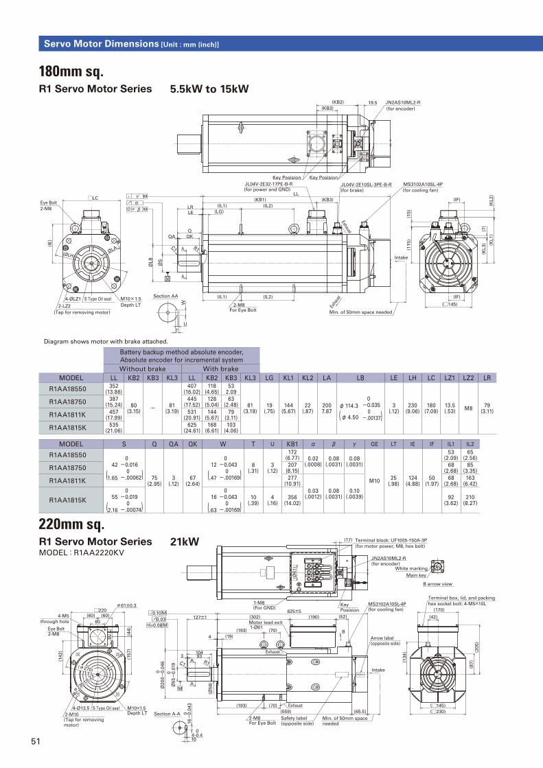
51
Servo Motor Dimensions [Unit : mm (inch)]
(302)
625±5□220
2-M10
Ø2
00
0 -0.0
46
4-Ø13.5
127±1
4 (19)
(□230)
(□145)
(134)
Ø55
0 -0.0
19
(Tap for removing motor)
S Type Oil seal
(193) (70)
Intake
(193) (70)
(60) (60)
(559) (65.5)
Min. of 50mm space needed
Safety label (opposite side)
(190)
(170)
(205)
(142)
933104
(Ø58)
R1C1
(52) (42)
60
4-M5
60
(Ø61)
(17)
(157)
through hole
(44)
16
0 -0.0
43
4-0.4 0
10
Depth LTM10×1.5
(87)
B arrow view
Key Posision
0.08 M
0.03
0.10 M
Arrow label (opposite side)
For Eye Bolt2-M8
Eye Bolt2-M8
(for encoder)
JN2AS10ML2-R
Terminal box, lid, and packing1-M8(For GND)
Terminal block: UF1005-150A-3P
(for motor power, M8, hex bolt)
hex socket bolt: 4-M5×10L
MA
A
MS3102A10SL-4P(for cooling fan)
Motor lead exit1-Ø61
W U
V
B
Section A-A
Main key
White marking
∅61±0.3
Exhaust
Exhaust
∅235±0.2
3
(∅270)
180mm sq.R1 Servo Motor Series 5.5kW to 15kW
Battery backup method absolute encoder,
Absolute encoder for incremental system
Without brake With brake
MODEL LL KB2 KB3 KL3 LL KB2 KB3 KL3 LG KL1 KL2 LA LB LE LH LC LZ1 LZ2 LR
R1AA18550352
(13.86)
80(3.15)
- 81(3.19)
407(16.02)
118(4.65)
532.09
81(3.19)
19(.75)
144(5.67)
22(.87)
2007.87
φ 114.3
(φ 4.50
0-0.035 0-.00137)
3(.12)
230(9.06)
180(7.09)
13.5(.53)
M879
(3.11)
R1AA18750387
(15.24)445
(17.52)128
(5.04)63
(2.48)
R1AA1811K457
(17.99)531
(20.91)144
(5.67)79
(3.11)
R1AA1815K535
(21.06)625
(24.61)168
(6.61)103
(4.06)
MODEL S Q QA QK W T U KB1 α β γ QE LT IE IF IL1 IL2
R1AA18550
42
(1.65
0-0.016 0-.00062) 75
(2.95)3
(.12)67
(2.64)
12
(.47
0-0.043 0-.00169)
8(.31)
3(.12)
172(6.77) 0.02
(.0008)0.08
(.0031)0.08
(.0031)
M1025
(.98)124
(4.88)50
(1.97)
53(2.09)
65(2.56)
R1AA18750207
(8.15)68
(2.68)85
(3.35)
R1AA1811K277
(10.91)
0.03(.0012)
0.08(.0031)
0.10(.0039)
68(2.68)
163(6.42)
R1AA1815K55
(2.16
0-0.019 0-.00074)
16
(.63
0-0.043 0-.00169)
10(.39)
4(.16)
356(14.02)
92(3.62)
210(8.27)
LL
For Eye Bolt2-M8
LE
ØL
B
(LG)
Min. of 50mm space needed
Exha
ust
Intake
M
M
γαβ
(KB1)
(for power and GND)
JL04V-2E32-17PE-B-R
(for cooling fan)
MS3102A10SL-4P
Key Posision
(IL1) (IL2)
Q
LR
QK
ØS
MA
QA
C1 A
(KB2)
(for encoder)
JN2AS10ML2-R
(15)
(KL2)
(□145)
(7)
(KL3)
(115)
(KL1)
□LC
4-ØLZ1
ØLA
(IE
)
(ØLH)
(Tap for removing motor)
2-LZ2
S Type Oil seal
2-M8
Eye Bolt
M10×1.5
Depth LT
R1
Key Posision
19.5
(IL1) (IL2)
(IF)
(IF)
JL04V-2E10SL-3PE-B-R
(for brake)
(KB3)
(KB3)
Exhaust
W
T
U
Section AA
Diagram shows motor with brake attached.
220mm sq.R1 Servo Motor Series 21kWMODEL:R1AA2220KV
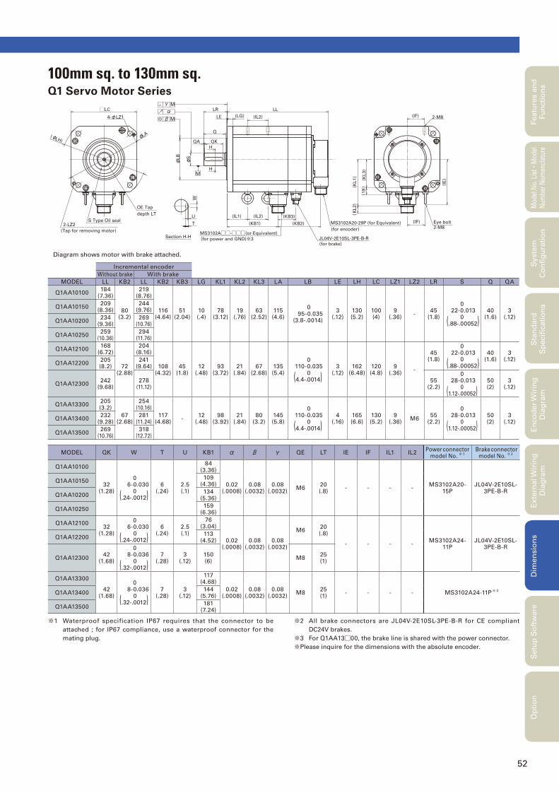
52
Featu
res a
nd
Fu
ncti
on
sM
odel
No.
Lis
t
・Mod
el
Num
ber
Nom
encl
atur
eS
tan
dard
S
pecifi
cati
on
sE
nco
der
Wir
ing
D
iag
ram
Exte
rnal W
irin
g
Dia
gra
mD
imen
sio
ns
Setu
p S
oft
ware
Op
tio
nS
yste
m
Co
nfi
gu
rati
on
※1 Waterproof specification IP67 requires that the connector to be
attached ; for IP67 compliance, use a waterproof connector for the
mating plug.
※2 All brake connectors are JL04V-2E10SL-3PE-B-R for CE compliant
DC24V brakes.
※3 For Q1AA13□00, the brake line is shared with the power connector.
※Please inquire for the dimensions with the absolute encoder.
Incremental encoder
Without brake With brake
MODEL LL KB2 LL KB2 KB3 LG KL1 KL2 KL3 LA LB LE LH LC LZ1 LZ2 LR S Q QA
Q1AA10100184
(7.36)
80(3.2)
219(8.76)
116(4.64)
51(2.04)
10(.4)
78(3.12)
19(.76)
63(2.52)
115(4.6)
0 95-0.035(3.8-.0014)
3(.12)
130(5.2)
100(4)
9(.36)
-45
(1.8)
0 22-0.013
0 (.88-.00052)
40(1.6)
3(.12)
Q1AA10150209
(8.36)244
(9.76)
Q1AA10200234
(9.36)269
(10.76)
Q1AA10250259
(10.36)294
(11.76)
Q1AA12100168
(6.72)
72(2.88)
204(8.16)
108(4.32)
45(1.8)
12(.48)
93(3.72)
21(.84)
67(2.68)
135(5.4)
0 110-0.035
0(4.4-.0014)
3(.12)
162(6.48)
120(4.8)
9(.36)
-
45(1.8)
0 22-0.013
0 (.88-.00052)
40(1.6)
3(.12)
Q1AA12200205(8.2)
241(9.64)
Q1AA12300242
(9.68)278
(11.12)55
(2.2)
0 28-0.013
0(1.12-.00052)
50(2)
3(.12)
Q1AA13300205(3.2)
67(2.68)
254(10.16)
117(4.68)
-12
(.48)98
(3.92)21
(.84)80
(3.2)145(5.8)
0 110-0.035
0(4.4-.0014)
4(.16)
165(6.6)
130(5.2)
9(.36)
M655
(2.2)
0 28-0.013
0(1.12-.00052)
50(2)
3(.12)
Q1AA13400232
(9.28)281
(11.24)
Q1AA13500269
(10.76)318
(12.72)
MODEL QK W T U KB1 α β γ QE LT IE IF IL1 IL2Power
connector
model No. ※ 1
Brake connector
model No. ※ 2
Q1AA10100
32(1.28)
0 6-0.030
0(.24-.0012)
6(.24)
2.5(.1)
84(3.36)
0.02(.0008)
0.08(.0032)
0.08(.0032)
M620(.8)
- - - -MS3102A20-
15PJL04V-2E10SL-
3PE-B-R
Q1AA10150109
(4.36)
Q1AA10200134
(5.36)
Q1AA10250159
(6.36)
Q1AA1210032
(1.28)
0 6-0.030
0(.24-.0012)
6(.24)
2.5(.1)
76(3.04)
0.02(.0008)
0.08(.0032)
0.08(.0032)
M620(.8)
- - - -MS3102A24-
11PJL04V-2E10SL-
3PE-B-R
Q1AA12200113
(4.52)
Q1AA1230042
(1.68)
0 8-0.036
0(.32-.0012)
7(.28)
3(.12)
150(6)
M825(1)
Q1AA13300
42(1.68)
0 8-0.036
0(.32-.0012)
7(.28)
3(.12)
117(4.68)
0.02(.0008)
0.08(.0032)
0.08(.0032)
M825(1)
- - - - MS3102A24-11P※ 3
Q1AA13400144
(5.76)
Q1AA13500181
(7.24)
MS3102A20-29P (for Equivalent)
Section H-H
(Tap for removing motor)
S Type Oil seal2-LZ2
LH)(φ
OE Tap
depth LT
φLA
□LC
4-φLZ1
M
β M
αγ
MS3102A□□-□□□(or Equivalent)
(for power and GND)※3 JL04V-2E10SL-3PE-B-R
(for brake)
Q
T
U
W
LB
φS
φM
QA
H
QK
H
(IL1) (IL2)
(KB1)
LR
LE (LG) (IL2)
(KB2)
(KB3)
(KL1)
(for encoder)
KL2
()
)( 1
9(K
L3)
LL
(IF)
(IE
)
2-M8Eye bolt
(IF) 2-M8
100mm sq. to 130mm sq.Q1 Servo Motor Series
Diagram shows motor with brake attached.
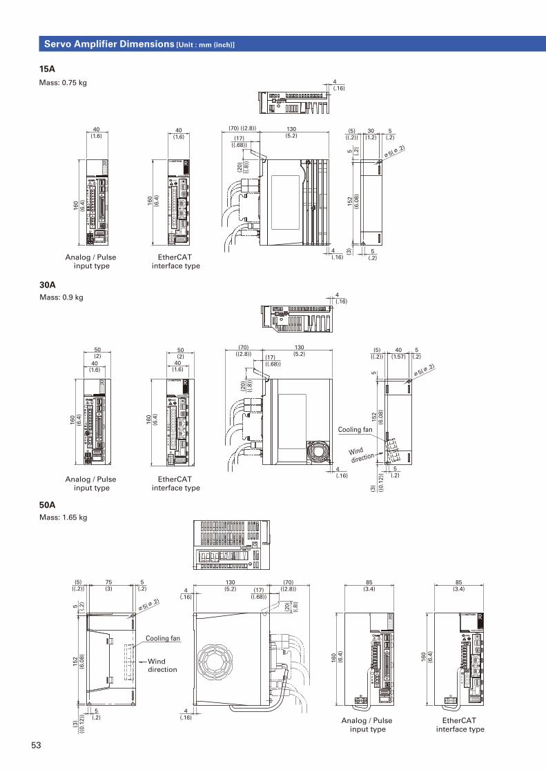
53
130(5.2)
(70)((2.8))(17)
((.68))
(20
)
((.8
))
160
(6.4
)
85(3.4)
5(.2)
75(3)
(5)((.2))
5(.
2)
152
(6.0
8)
(3)
((0.1
2))
5(.2)
4(.16)
4(.16)
∅5(∅.2)
Wind direction
Cooling fan
BCN
(17)((.68))
(20)
((.8
))
130(5.2)
(70)((2.8))
4(.16)
4(.16)
5(.2)
5(.2)
40(1.57)
(5)((.2))
5152
(6.0
8)
(3)
((0.1
2))
∅5(∅.2)
Wind
direction
Cooling fan
15A
50A
30A
Analog / Pulse input type
EtherCAT interface type
Analog / Pulse input type
EtherCAT interface type
Analog / Pulse input type
EtherCAT interface type
Mass: 0.75 kg
Mass: 1.65 kg
Mass: 0.9 kg
(17)((.68))
(20)
((.8
))
130(5.2)
(70) ((2.8))40(1.6)
40(1.6)
160
(6.4
)
160
(6.4
)
4(.16)
4(.16)
30(1.2)
(5)((.2))
5(.2)
5(.
2)
152
(6.0
8)
(3)
∅5(∅.2)
5(.2)
160
(6.4
)
160
(6.4
)
40(1.6)
50(2)
40(1.6)
50(2)
160
(6.4
)
85(3.4)
Servo Amplifier Dimensions [Unit : mm (inch)]
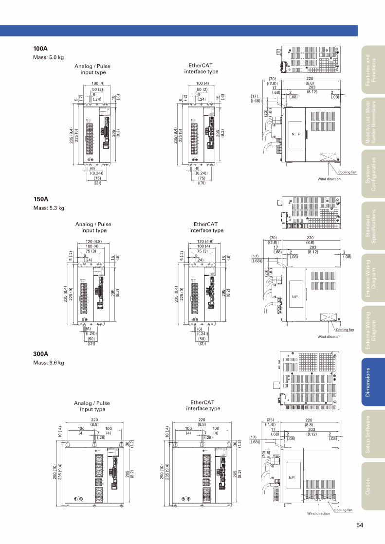
54
(6)((0.24))
(75)((3))
(6)((0.24))
(75)((3))
6 (.24)
50 (2)
235 (
9.4
)
225 (
9)
235 (
9.4
)
225 (
9)
5 (.2)
205
(8.2
)
205
(8.2
)
15
(.6)
5 (.2)
15
(.6)
100 (4)
6 (.24)
50 (2)
100 (4)
5 (
.2)
15
(.6)
5 (
.2)
15
(.6)
203(8.12)
220(8.8)
2(.08)
2(.08)
17(.68)
(70)((2.8))
(17)((.68))
(20)
((.8
))
203(8.12)
220(8.8)
2(.08)
2(.08)
203(8.12)
220(8.8)
2(.08)
2(.08)
17(.68)
(70)((2.8))
(17)((.68))
17(.68)
(17)((.68))
(20)
((.8
))
(20)
((.8
))
N.P.
Wind direction
Cooling fan
N.P.
Cooling fan
Wind direction
75 (3)
120 (4.8)
100 (4)
6 (.24)
75 (3)
120 (4.8)
100 (4)
6 (.24)
225 (
9)
235 (
9.4
)
225 (
9)
235 (
9.4
)
(50)((2))
(6)((.24))
(50)((2))
(6)((.24))
205
(8.2
)
205
(8.2
)
220(8.8)
100(4)
100(4)7
(.28)
220(8.8)
100(4)
100(4)7
(.28)
250 (
10)
235 (
9.4
)10
(.4
)
250 (
10)
235 (
9.4
)10
(.4
)
205
(8.2
)30
(1.2
)
205
(8.2
)30
(1.2
)
Wind directionCooling fan
(35)((1.4))
N.P.
100A
Mass: 5.0 kg
300A
Mass: 9.6 kg
150A
Mass: 5.3 kg
Analog / Pulse input type
EtherCAT interface type
Analog / Pulse input type
EtherCAT interface type
Analog / Pulse input type
EtherCAT interface type
Featu
res a
nd
Fu
ncti
on
sM
odel
No.
Lis
t
・Mod
el
Num
ber
Nom
encl
atur
eS
tan
dard
S
pecifi
cati
on
sE
nco
der
Wir
ing
D
iag
ram
Exte
rnal W
irin
g
Dia
gra
mD
imen
sio
ns
Setu
p S
oft
ware
Op
tio
nS
yste
m
Co
nfi
gu
rati
on
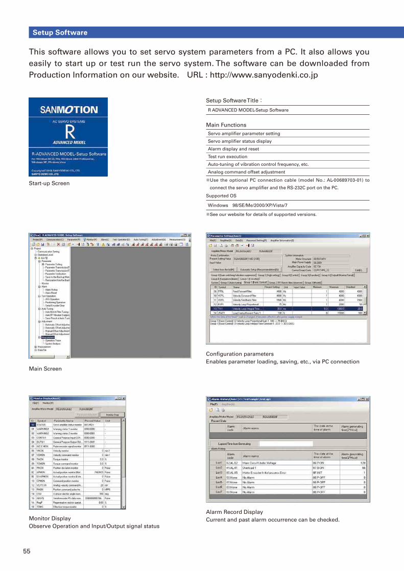
55
This software allows you to set servo system parameters from a PC. It also allows you
easily to start up or test run the servo system. The software can be downloaded from
Production Information on our website. URL : http://www.sanyodenki.co.jp
Start-up Screen
Main Screen
Alarm Record Display
Current and past alarm occurrence can be checked.
Confi guration parameters
Enables parameter loading, saving, etc., via PC connection
Setup Software Title:R ADVANCED MODEL-Setup Software
Main Functions
Servo amplifi er parameter setting
Servo amplifi er status display
Alarm display and reset
Test run execution
Auto-tuning of vibration control frequency, etc.
Analog command offset adjustment
※ Use the optional PC connection cable (model No.: AL-00689703-01) to
connect the servo amplifi er and the RS-232C port on the PC.
Supported OS
Windows 98/SE/Me/2000/XP/Vista/7
※See our website for details of supported versions.
Monitor Display
Observe Operation and Input/Output signal status
Setup Software
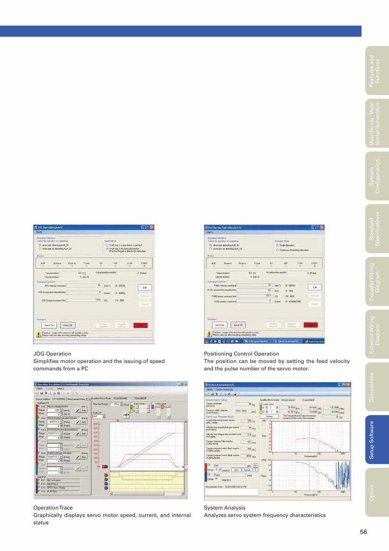
56
JOG Operation
Simplifi es motor operation and the issuing of speed
commands from a PC
Positioning Control Operation
The position can be moved by setting the feed velocity
and the pulse number of the servo motor.
Operation Trace
Graphically displays servo motor speed, current, and internal
status
System Analysis
Analyzes servo system frequency characteristics
Featu
res a
nd
Fu
ncti
on
sM
odel
No.
Lis
t
・Mod
el
Num
ber
Nom
encl
atur
eS
tan
dard
S
pecifi
cati
on
sE
nco
der
Wir
ing
D
iag
ram
Exte
rnal W
irin
g
Dia
gra
mD
imen
sio
ns
Setu
p S
oft
ware
Op
tio
nS
yste
m
Co
nfi
gu
rati
on
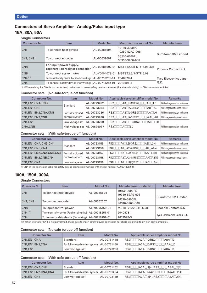
57
Connectors of Servo Amplifi er Analog/Pulse input type
15A, 30A, 50A
Single Connectors
Connector No. Item Model No. Manufacturer model No. Manufacturer
CN1 To connect host device AL-0038559410150-3000PE
10350-52A0-008Sumitomo 3M Limited
EN1, EN2 To connect encoder AL-0063260736210-0100PL
36310-3200-008
CNAFor input power supply,
regeneration resistor connectionAL-00686902-01 MSTBT2.5/8-STF-5.08LUB
Phoenix Contact.K.K
CNB To connect servo motor AL-Y0004079-01 MSTBT2.5/3-STF-5.08
CN4 ※ 1
To connect safety device (For short-circuiting) AL-00718251-01 2040978-1 Tyco Electronics Japan
G.K.CN4 To connect safety device (For wiring) AL-00718252-01 2013595-3
※1 When wiring for CN4 is not performed, make sure to insert safety device connector (for short-circuiting) to CN4 on servo amplifi er.
Connector sets (No safe-torque-off function)
Connector sets (With safe-torque-off function)
Connector No. Item Model No. Applicable servo amplifi er model No. Remarks
CN1,EN1,CNA,CNBStandard
AL-00723282 RS2□□□A0□L0/RS2□□□A8□L0 Without regeneration resistance
CN1,EN1,CNB AL-00723284 RS2□□□A0□A0/RS2□□□A8□A0 With regeneration resistance
CN1,EN1,EN2,CNA,CNB For fully closed
control system
AL-00723286 RS2□□□A2□L0/RS2□□□AA□L0 Without regeneration resistance
CN1,EN1,EN2,CNB AL-00723288 RS2□□□A2□A0/RS2□□□AA□A0 With regeneration resistance
CN1,EN1 Low voltage set AL-00723290 RS2□□□A0□□0/RS2□□□A8□□0 -CNA,CNB High voltage set AL-00696037 RS2□□□A□□L0 Without regeneration resistance
Connector No. Item Model No. Applicable servo amplifi er model No. Remarks
CN1,EN1,CNA,CNB,CN4Standard
AL-00723155 RS2□□□A0□L2(4)/RS2□□□A8□L2(4) Without regeneration resistance
CN1,EN1,CNB,CN4 AL-00723156 RS2□□□A0□A2(4)/RS2□□□A8□A2(4) With regeneration resistance
CN1,EN1,EN2,CNA,CNB,CN4 For fully closed
control system
AL-00723157 RS2□□□A2□L2(4)/RS2□□□AA□L2(4) Without regeneration resistance
CN1,EN1,EN2,CNB,CN4 AL-00723158 RS2□□□A2□A2(4)/RS2□□□AA□A2(4) With regeneration resistance
CN1,EN1,CN4 Low voltage set AL-00723159 RS2□□□A0□□2(4)/RS2□□□A8□□2(4) -※ CN4 of the connector set is for safety device connection (wiring) with model number AL-00718252-01.
Option
100A, 150A, 300A
Single Connectors
Connector No. Item Model No. Manufacturer model No. Manufacturer
CN1 To connect host device AL-0038559410150-3000PE
10350-52A0-008Sumitomo 3M Limited
EN1, EN2 To connect encoder AL-0063260736210-0100PL
36310-3200-008
CNA To input control power AL-Y0005159-01 MSTBT2.5/2-STF-5.08 Phoenix Contact.K.K
CN4 ※ 1
To connect safety device (For short-circuiting) AL-00718251-01 2040978-1Tyco Electronics Japan G.K.
CN4 To connect safety device (For wiring) AL-00718252-01 2013595-3
※1 When wiring for CN4 is not performed, make sure to insert safety device connector (for short-circuiting) to CN4 on servo amplifi er.
Connector sets (No safe-torque-off function)
Connector sets (With safe-torque-off function)
Connector No. Item Model No. Applicable servo amplifi er model No.
CN1,EN1,CNA Standard AL-00751448 RS2□□□A0A□0/RS2□□□A8A□0
CN1,EN1,EN2,CNA For fully closed control system AL-00751450 RS2□□□A2A□0/RS2□□□AAA□0
CN1,EN1 Low voltage set AL-00723290 RS2□□□A0A□0/RS2□□□A8A□0
Connector No. Item Model No. Applicable servo amplifi er model No.
CN1,EN1,CNA,CN4 Standard AL-00751452 RS2□□□A0A□2(4)/RS2□□□A8A□2(4)
CN1,EN1,EN2,CNA,CN4 For fully closed control system AL-00751454 RS2□□□A2A□2(4)/RS2□□□AAA□2(4)
CN1,EN1,CN4 Low voltage set AL-00723159 RS2□□□A0A□2(4)/RS2□□□A8A□2(4)
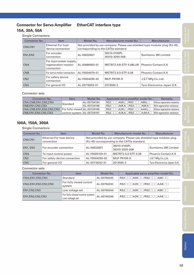
58
Connector No. Item Model No. Manufacturer model No. Manufacturer
CN0,CN1Ethernet For host
device connection
Not provided by our company. Please use shielded type modular plug (RJ-45)
corresponding to the CAT5e standard.
EN1,EN2For encoder
connectionAL-00632607
36210-0100PL
36310-3200-008Sumitomo 3M Limited
CNA
For input power supply,
regeneration resistor
connection
AL-00686902-01 MSTBT2.5/8-STF-5.08LUB Phoenix Contact.K.K
CNB For servo motor connection AL-Y0004079-01 MSTBT2.5/3-STF-5.08 Phoenix Contact.K.K
CN2For safety device
connectionAL-Y0004290-02 MUF-PK10K-X J.S.T Mfg Co.,Ltd.
CN3 For general I/O AL-00718252-01 2013595-3 Tyco Electronics Japan G.K.
Connector sets
Connector No. Item Model No. Applicable servo amplifi er model No. Remarks
CNA,CNB,EN1,CN2,CN3Standard
AL-00734194 RS2□□□A0KL□/RS2□□□A8KL□ Without regeneration resistance
CNB,EN1,CN2,CN3 AL-00734196 RS2□□□A0KA□/RS2□□□A8KA□ With regeneration resistance
CNA,CNB,EN1,EN2,CN2,CN3 For fully closed
control system
AL-00734195 RS2□□□A2KL□/RS2□□□AAKL□ Without regeneration resistance
CNB,EN1,EN2,CN2,CN3 AL-00734197 RS2□□□A2KA□/RS2□□□AAKA□ With regeneration resistance
Featu
res a
nd
Fu
ncti
on
sM
odel
No.
Lis
t
・Mod
el
Num
ber
Nom
encl
atur
eS
tan
dard
S
pecifi
cati
on
sE
nco
der
Wir
ing
D
iag
ram
Exte
rnal W
irin
g
Dia
gra
mD
imen
sio
ns
Setu
p S
oft
ware
Op
tio
nS
yste
m
Co
nfi
gu
rati
on
Connector for Servo Amplifi er EtherCAT interface type
15A, 30A, 50A
Single Connectors
100A, 150A, 300A
Single Connectors
Connector No. Item Model No. Manufacturer model No. Manufacturer
CN0,CN1Ethernet For host device
connection
Not provided by our company. Please use shielded type modular plug
(RJ-45) corresponding to the CAT5e standard.
EN1, EN2 For encoder connection AL-0063260736210-0100PL
36310-3200-008Sumitomo 3M Limited
CNA To input control power AL-Y0005159-01 MSTBT2.5/2-STF-5.08 Phoenix Contact.K.K
CN2 For safety device connection AL-Y0004290-02 MUF-PK10K-X J.S.T Mfg Co.,Ltd.
CN3 For general I/O AL-00718252-01 2013595-3 Tyco Electronics Japan G.K.
Connector sets
Connector No. Item Model No. Applicable servo amplifi er model No.
CNA,EN1,CN2,CN3 Standard AL-00756240 RS2□□□A0K□□/RS2□□□A8K□□
CNA,EN1,EN2,CN2,CN3For fully closed control
systemAL-00756242 RS2□□□A2K□□/RS2□□□AAK□□
EN1,CN2,CN3 Low voltage set AL-00756244 RS2□□□A0K□□/RS2□□□A8K□□
EN1,EN2,CN2,CN3For fully closed control system
Low voltage setAL-00756246 RS2□□□A2K□□/RS2□□□AAK□□
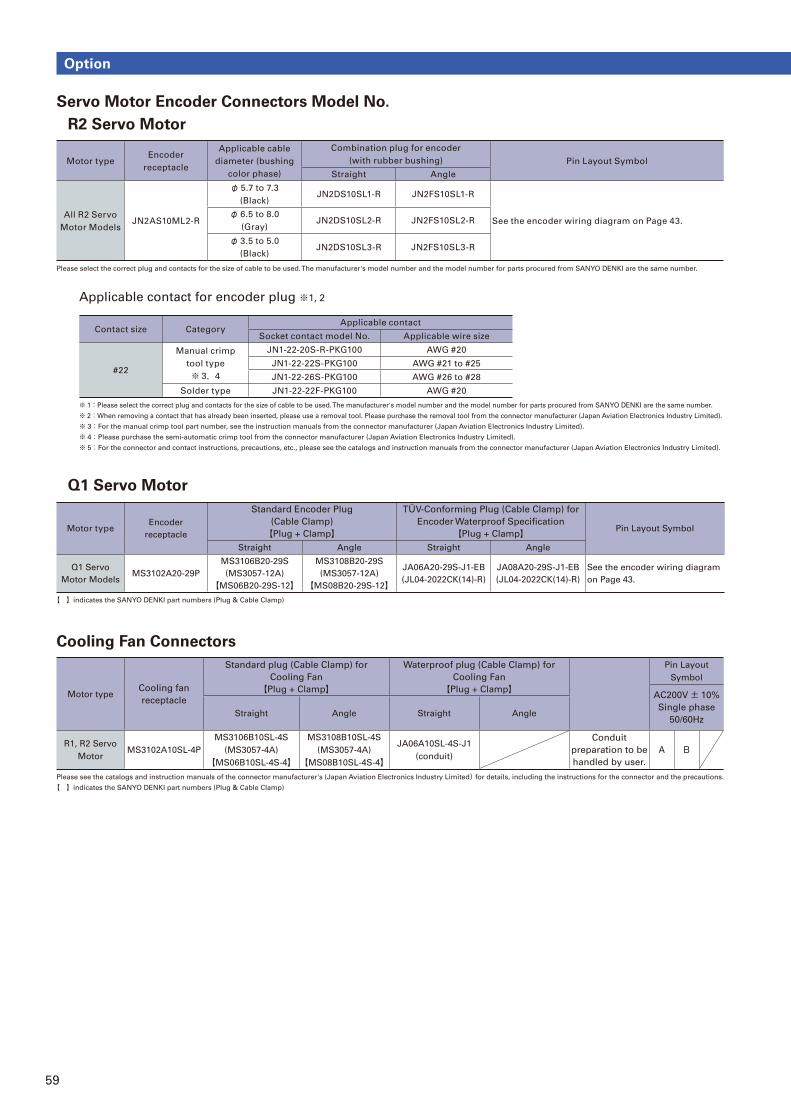
59
Option
Servo Motor Encoder Connectors Model No.
R2 Servo Motor
Applicable contact for encoder plug ※1, 2
Q1 Servo Motor
Cooling Fan Connectors
Motor typeEncoder
receptacle
Standard Encoder Plug
(Cable Clamp)
【Plug + Clamp】
TÜV-Conforming Plug (Cable Clamp) for
Encoder Waterproof Specifi cation
【Plug + Clamp】 Pin Layout Symbol
Straight Angle Straight Angle
Q1 Servo
Motor ModelsMS3102A20-29P
MS3106B20-29S
(MS3057-12A)
【MS06B20-29S-12】
MS3108B20-29S
(MS3057-12A)
【MS08B20-29S-12】
JA06A20-29S-J1-EB
(JL04-2022CK(14)-R)
JA08A20-29S-J1-EB
(JL04-2022CK(14)-R)
See the encoder wiring diagram
on Page 43.
【 】indicates the SANYO DENKI part numbers (Plug & Cable Clamp)
Motor typeCooling fan
receptacle
Standard plug (Cable Clamp) for
Cooling Fan
【Plug + Clamp】
Waterproof plug (Cable Clamp) for
Cooling Fan
【Plug + Clamp】
Pin Layout
Symbol
AC200V± 10%
Single phase
50/60HzStraight Angle Straight Angle
R1, R2 Servo
MotorMS3102A10SL-4P
MS3106B10SL-4S
(MS3057-4A)
【MS06B10SL-4S-4】
MS3108B10SL-4S
(MS3057-4A)
【MS08B10SL-4S-4】
JA06A10SL-4S-J1
(conduit)
Conduit
preparation to be
handled by user.
A B
Please see the catalogs and instruction manuals of the connector manufacturer's (Japan Aviation Electronics Industry Limited)for details, including the instructions for the connector and the precautions.
【 】indicates the SANYO DENKI part numbers (Plug & Cable Clamp)
Motor typeEncoder
receptacle
Applicable cable
diameter (bushing
color phase)
Combination plug for encoder
(with rubber bushing) Pin Layout Symbol
Straight Angle
All R2 Servo
Motor ModelsJN2AS10ML2-R
φ 5.7 to 7.3
(Black)JN2DS10SL1-R JN2FS10SL1-R
See the encoder wiring diagram on Page 43.φ 6.5 to 8.0
(Gray)JN2DS10SL2-R JN2FS10SL2-R
φ 3.5 to 5.0
(Black)JN2DS10SL3-R JN2FS10SL3-R
Please select the correct plug and contacts for the size of cable to be used. The manufacturer's model number and the model number for parts procured from SANYO DENKI are the same number.
Contact size CategoryApplicable contact
Socket contact model No. Applicable wire size
#22
Manual crimp
tool type
※ 3,4
JN1-22-20S-R-PKG100 AWG #20
JN1-22-22S-PKG100 AWG #21 to #25
JN1-22-26S-PKG100 AWG #26 to #28
Solder type JN1-22-22F-PKG100 AWG #20
※ 1:Please select the correct plug and contacts for the size of cable to be used. The manufacturer's model number and the model number for parts procured from SANYO DENKI are the same number.
※ 2:When removing a contact that has already been inserted, please use a removal tool. Please purchase the removal tool from the connector manufacturer (Japan Aviation Electronics Industry Limited).
※ 3:For the manual crimp tool part number, see the instruction manuals from the connector manufacturer (Japan Aviation Electronics Industry Limited).
※ 4:Please purchase the semi-automatic crimp tool from the connector manufacturer (Japan Aviation Electronics Industry Limited).
※ 5:For the connector and contact instructions, precautions, etc., please see the catalogs and instruction manuals from the connector manufacturer (Japan Aviation Electronics Industry Limited).
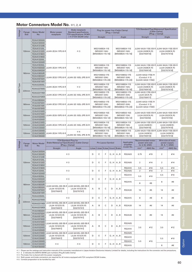
60
Featu
res a
nd
Fu
ncti
on
sM
odel
No.
Lis
t
・Mod
el
Num
ber
Nom
encl
atur
eS
tan
dard
S
pecifi
cati
on
sE
nco
der
Wir
ing
D
iag
ram
Exte
rnal W
irin
g
Dia
gra
mD
imen
sio
ns
Setu
p S
oft
ware
Op
tio
nS
yste
m
Co
nfi
gu
rati
on
Motor Connectors Model No. ※1, 2, 4
※ 1:Please see the catalogs and instruction manuals of the connector manufacturer's (Japan Aviation Electronics Industry Limited) for details, including the instructions for the connector and the precautions.
※ 2:【 】 indicates the SANYO DENKI part numbers (Plug & Cable Clamp)
※ 3: The brake line is shared with the power receptacle.
※ 4:Both power and brake connectors are required for all motors equipped with TÜV compliant DC24V brakes.
※ 5:Conduit preparation to be handled by user.
Vo
ltag
e
Flange
Size
Motor Model
No.
Motor power
receptacle
Brake receptacle
Standard specifi cations,
TÜV specifi cations: DC90V
(※ 4 TÜV: DC24V only)
Plug for power line (Cable Clamp)
【Plug + Clamp】
TÜV-Standard Plug Waterproof Specifi cation
(Cable Clamp)
【Plug + Clamp】
Straight Angle Straight Angle
200V
Typ
e
130mm
R2AA13050H
JL04V-2E24-11PE-B-R ※ 3
MS3106B24-11S
(MS3057-16A)
【MS06B24-11S-16】
MS3108B24-11S
(MS3057-16A)
【MS08B24-11S-16】
JL04V-6A24-11SE-EB-R
(JL04-2428CK-R)
【332706X10】
JL04V-8A24-11SE-EB-R
(JL04-2428CK-R)
【332707X10】
R2AA13050D
R2AA13120B
R2AA13120L
R2AA13120D
R2AA13180H
R2AA13180D
R2AA13200L
R2AA13200D
180mm
R2AA18350L
JL04V-2E24-11PE-B-R ※ 3
MS3106B24-11S
(MS3057-16A)
【MS06B24-11S-16】
MS3108B24-11S
(MS3057-16A)
【MS08B24-11S-16】
JL04V-6A24-11SE-EB-R
(JL04-2428CK-R)
【332706X10】
JL04V-8A24-11SE-EB-R
(JL04-2428CK-R)
【332707X10】R2AA18350D
R2AA18450H
R2AA18550R
JL04V-2E32-17PE-B-R JL04V-2E-10SL-3PE-B-R
MS3106B32-17S
(MS3057-20A)
【MS06B32-17S-20】
MS3108B32-17S
(MS3057-20A)
【MS08B32-17S-20】
JL04V-6A32-17SE-R
(Conduit ※ 5)
【JL04V-6A32-17SE】
R2AA18550H
R2AA18750H
R2AA1811KR
220mm
R2AA22500LJL04V-2E24-11PE-B-R ※ 3
MS3106B24-11S
(MS3057-16A)
【MS06B24-11S-16】
MS3108B24-11S
(MS3057-16A)
【MS08B24-11S-16】
JL04V-6A24-11SE-EB-R
(JL04-2428CK-R)
【332706X10】
JL04V-8A24-11SE-EB-R
(JL04-2428CK-R)
【332707X10】R2AA22700S
R2AA2211KBJL04V-2E32-17PE-B-R JL04V-2E-10SL-3PE-B-R
MS3106B32-17S
(MS3057-20A)
【MS06B32-17S-20】
MS3108B32-17S
(MS3057-20A)
【MS08B32-17S-20】
JL04V-6A32-17SE-EB-R
(JL04-32CK-R)
【332706X11】R2AA2215KB
180mm
R1AA18550H
JL04V-2E32-17PE-B-R JL04V-2E-10SL-3PE-B-R
MS3106B32-17S
(MS3057-20A)
【MS06B32-17S-20】
MS3108B32-17S
(MS3057-20A)
【MS08B32-17S-20】
JL04V-6A32-17SE-R
(Conduit ※ 5)
【JL04V-6A32-17SE】
R1AA18750H
R1AA1811KR
R1AA1815KB
100mm
Q1AA10100D
JL04V-2E20-15PE-B-R JL04V-2E-10SL-3PE-B-R
MS3106B20-15S
(MS3057-12A)
【MS06B20-15S-12】
MS3108B20-15S
(MS3057-12A)
【MS08B20-15S-12】
JL04V-6A20-15SE-EB-R
(JL04-2022CK-R)
【332706X5】
JL04V-8A20-15SE-EB-R
(JL04-2022CK-R)
【332707X5】
Q1AA10150D
Q1AA10200D
Q1AA10250D
120mm
Q1AA12100D
JL04V-2E24-11PE-B-R JL04V-2E-10SL-3PE-B-R
MS3106B24-11S
(MS3057-16A)
【MS06B24-11S-16】
MS3108B24-11S
(MS3057-16A)
【MS08B24-11S-16】
JL04V-6A24-11SE-EB-R
(JL04-2428CK)
【332706X10】
JL04V-8A24-11SE-EB-R
(JL04-2428CK)
【332707X10】Q1AA12200D
Q1AA12300D
130mm
Q1AA13300D
JL04V-2E24-11PE-B-R※ 4
(JL04V-2E-10SL-3PE-B-R)
MS3106B24-11S
(MS3057-16A)
【MS06B24-11S-16】
MS3108B24-11S
(MS3057-16A)
【MS08B24-11S-16】
JL04V-6A24-11SE-EB-R
(JL04-2428CK)
【332706X10】
JL04V-8A24-11SE-EB-R
(JL04-2428CK)
【332707X10】Q1AA13400D
Q1AA13500D
Vo
lta
ge
Flange
Size
Motor Model
No.
TÜV-Standard Plug for
Brake Waterproof Specifi cation (Cable Clamp)
【Plug + Clamp】Pin Layout Symbol Applicable
amplifi er
model No.
Recommended motor
power wire size
(U, V, W, GND)
Wire size of main
power supply
(R, S, T, GND)
Straight Angle U phase V phase W phase Ground Brake mm2AWG No. mm2
AWG No.
200V
Typ
e
130mm
R2AA13050H
※ 3 D E F G , H A , B RS2A03 0.75 #19 2 #14R2AA13050D
R2AA13120B
R2AA13120L
※ 3 D E F G , H A , B RS2A05 2 #14 2 #14R2AA13120D
R2AA13180H
R2AA13180D
※ 3 D E F G , H A , B
RS2A10 5.5 #10 5.5 #10
R2AA13200L RS2A05 2 #14 2 #14
R2AA13200DRS2A10
5.5 #105.5 #10
180mm
R2AA18350L
※ 3 D E F G , H A , BR2AA18350D
RS2A15 8 #8R2AA18450H8 #8
R2AA18550RJL04V-6A10SL-3SE-EB-R
(JL04-1012CK-R)
【332706X1】
JL04V-8A10SL-3SE-EB-R
(JL04-1012CK-R)
【332707X1】A B C D A , B
R2AA18550H
RS2A30 14 #6 14 #6R2AA18750H
R2AA1811KR
220mm
R2AA22500L※ 3 D E F G , H A , B RS2A15 8 #8 8 #8
R2AA22700S
R2AA2211KB JL04V-6A10SL-3SE-EB-R
(JL04-1012CK-R)
【332706X1】
JL04V-8A10SL-3SE-EB-R
(JL04-1012CK-R)
【332707X1】A B C D A , B RS2A30 14 #6 14 #6
R2AA2215KB
180mm
R1AA18550HJL04V-6A10SL-3SE-EB-R
(JL04-1012CK-R)
【332706X1】
JL04V-8A10SL-3SE-EB-R
(JL04-1012CK-R)
【332707X1】A B C D A , B RS2A30 14 #6 14 #6
R1AA18750H
R1AA1811KR
R1AA1815KB
100mm
Q1AA10100DJL04V-6A10SL-3SE-EB-R
(JL04-1012CK-R)
【332706X1】
JL04V-8A10SL-3SE-EB-R
(JL04-1012CK-R)
【332707X1】A B C D A , B
RS2A05
3.5 #12 3.5 #12
Q1AA10150D
Q1AA10200DRS2A10
Q1AA10250D
120mm
Q1AA12100D JL04V-6A10SL-3SE-EB-R
(JL04-1012CK-R)
【332706X1】
JL04V-8A10SL-3SE-EB-R
(JL04-1012CK-R)
【332707X1】D E F G , H A , B
RS2A05
Q1AA12200DRS2A10
5.5 #10
5.5 #10Q1AA12300D
130mm
Q1AA13300D
※ 4 ※ 4 D E F G , H A , B
RS2A10
Q1AA13400DRS2A15 8 #8
Q1AA13500D
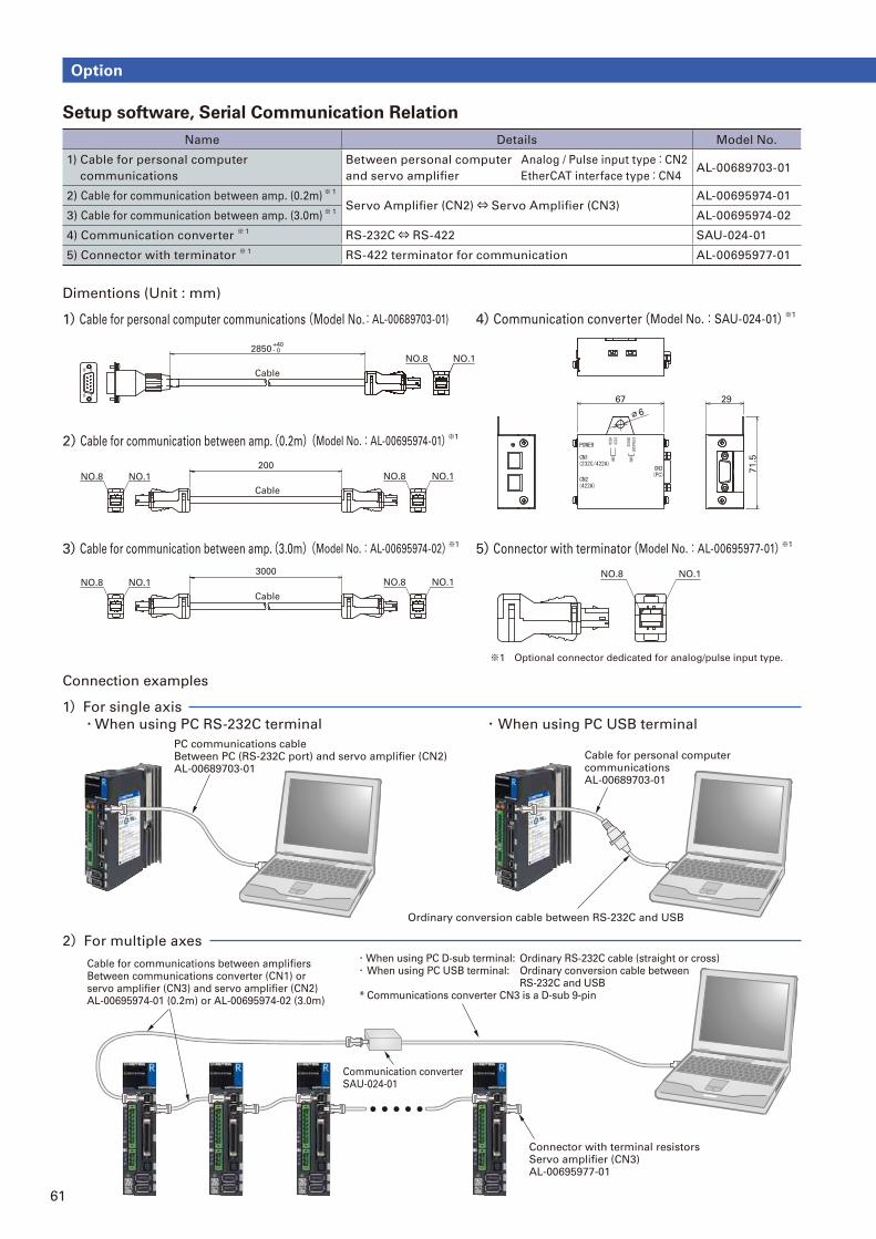
61
Dimentions (Unit : mm)
Connection examples
1)Cable for personal computer communications (Model No.:AL-00689703-01)
1)For single axis
・ When using PC USB terminal・When using PC RS-232C terminal
2)For multiple axes
4)Communication converter(Model No.:SAU-024-01)※1
5)Connector with terminator(Model No.:AL-00695977-01)※1
2)Cable for communication between amp.(0.2m)(Model No.:AL-00695974-01)※1
3)Cable for communication between amp.(3.0m)(Model No.:AL-00695974-02)※1
9
6
5
1
Cable
2850+40- 0
NO.1NO.8
NO.8 NO.1
Cable
200
NO.8 NO.1
71
.5
2967
∅6
NO.8 NO.1
Cable
3000
NO.8 NO.1NO.8 NO.1
※1 Optional connector dedicated for analog/pulse input type.
PC communications cableBetween PC (RS-232C port) and servo amplifier (CN2)AL-00689703-01
Cable for personal computer communicationsAL-00689703-01
Ordinary conversion cable between RS-232C and USB
Cable for communications between amplifiersBetween communications converter (CN1) or servo amplifier (CN3) and servo amplifier (CN2)AL-00695974-01 (0.2m) or AL-00695974-02 (3.0m)
・When using PC D-sub terminal: Ordinary RS-232C cable (straight or cross)・ When using PC USB terminal: Ordinary conversion cable between RS-232C and USB * Communications converter CN3 is a D-sub 9-pin
Communication converterSAU-024-01
Connector with terminal resistorsServo amplifier (CN3)AL-00695977-01
Setup software, Serial Communication Relation
Name Details Model No.
1) Cable for personal computer
communications
Between personal computer
and servo amplifi er
Analog / Pulse input type:CN2
EtherCAT interface type:CN4AL-00689703-01
2) Cable for communication between amp. (0.2m)※ 1
Servo Amplifi er (CN2)⇔ Servo Amplifi er (CN3)AL-00695974-01
3) Cable for communication between amp. (3.0m)※ 1
AL-00695974-02
4) Communication converter ※ 1
RS-232C⇔ RS-422 SAU-024-01
5) Connector with terminator ※ 1
RS-422 terminator for communication AL-00695977-01
Option
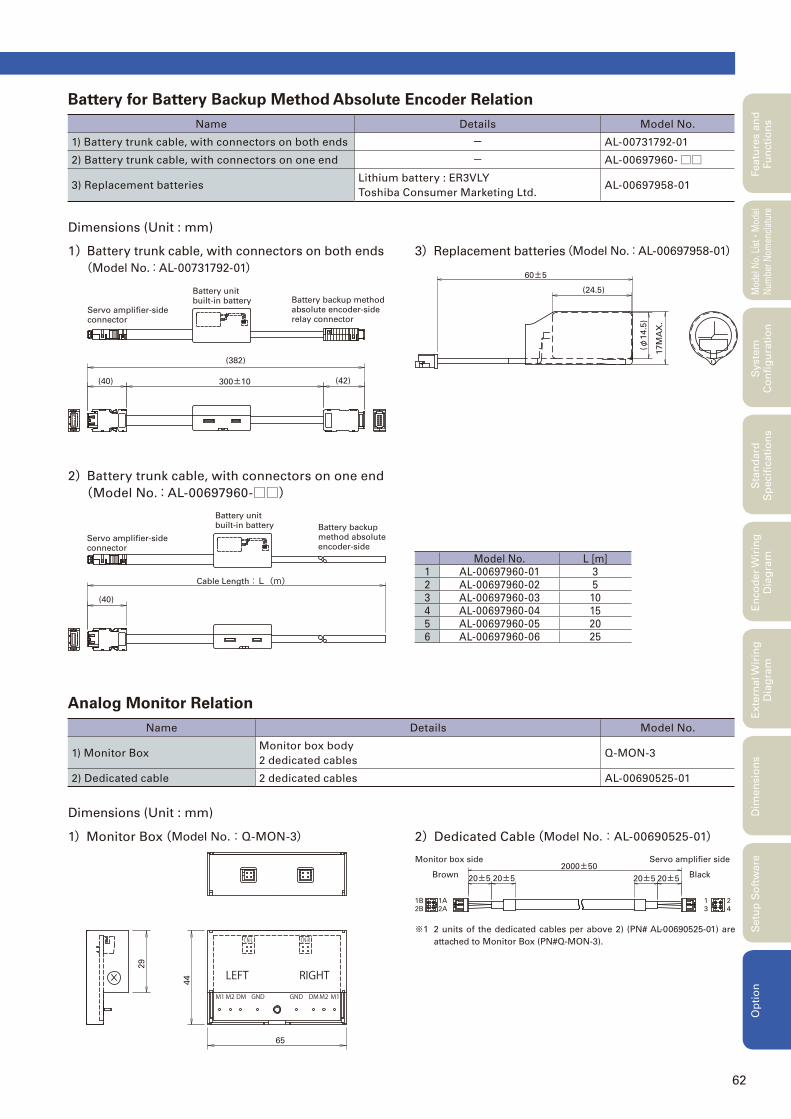
62
Dimensions (Unit : mm)
Dimensions (Unit : mm)
3) Replacement batteries(Model No.:AL-00697958-01)
1)Monitor Box(Model No.:Q-MON-3)
1) Battery trunk cable, with connectors on both ends
(Model No.:AL-00731792-01)
2)Dedicated Cable(Model No.:AL-00690525-01)
2) Battery trunk cable, with connectors on one end
(Model No.:AL-00697960-□□)
60±5
(φ1
4.5
)
17
MA
X.
(24.5)
(40)
Cable Length:L(m)
Battery unit built-in battery
Servo amplifier-side connector
Battery backup method absolute encoder-side
29
44
65
20±520±5
4
21
3
2000±50
20±520±5
1A
2A2B
1B
Monitor box side Servo amplifier side
Brown Black
Battery unit built-in battery
Servo amplifier-side connector
Battery backup method absolute encoder-side relay connector
(40)
(382)
300±10 (42)
Model No. L [m]
1 AL-00697960-01 3
2 AL-00697960-02 5
3 AL-00697960-03 10
4 AL-00697960-04 15
5 AL-00697960-05 20
6 AL-00697960-06 25
※1 2 units of the dedicated cables per above 2) (PN# AL-00690525-01) are
attached to Monitor Box (PN#Q-MON-3).
Battery for Battery Backup Method Absolute Encoder Relation
Name Details Model No.
1) Battery trunk cable, with connectors on both ends - AL-00731792-01
2) Battery trunk cable, with connectors on one end - AL-00697960-□□
3) Replacement batteriesLithium battery : ER3VLY
Toshiba Consumer Marketing Ltd.AL-00697958-01
Analog Monitor Relation
Name Details Model No.
1) Monitor BoxMonitor box body
2 dedicated cablesQ-MON-3
2) Dedicated cable 2 dedicated cables AL-00690525-01
Featu
res a
nd
Fu
ncti
on
sM
odel
No.
Lis
t
・Mod
el
Num
ber
Nom
encl
atur
eS
tan
dard
S
pecifi
cati
on
sE
nco
der
Wir
ing
D
iag
ram
Exte
rnal W
irin
g
Dia
gra
mD
imen
sio
ns
Setu
p S
oft
ware
Op
tio
nS
yste
m
Co
nfi
gu
rati
on
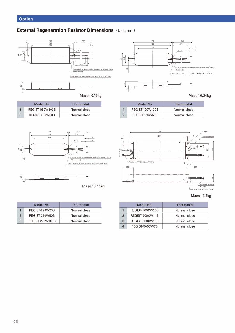
63
Model No. Thermostat
1 REGIST-500CW20B Normal close
2 REGIST-500CW14B Normal close
3 REGIST-500CW10B Normal close
4 REGIST-500CW7B Normal close
External Regeneration Resistor Dimensions (Unit: mm)
132122
300
6
φ4.3
6
270
120
100
Silicon Rubber Glass-braided Wire AWG20 0.5mm2, White
Silicon Rubber Glass-braided Wire AWG18 0.75mm2, Black
(Thermostat)
44
26
4.3
200
220
230 300
270
φ4.3
6
6
60
42
.72
0
1.2
4.3
Silicon Rubber Glass-braided Wire AWG20 0.5mm2, White
Silicon Rubber Glass-braided Wire AWG18 0.75mm2, Black
(Thermostat)
Mass:0.24kg
Mass:0.44kg
Mass:1.5kg
Model No. Thermostat
1 REGIST-080W100B Normal close
2 REGIST-080W50B Normal close
Model No. Thermostat
1 REGIST-220W20B Normal close
2 REGIST-220W50B Normal close
3 REGIST-220W100B Normal close
150
172
182 300
270
φ4.3
6
6
42
23.5
20
1.2
4.3
Silicon Rubber Glass-braided Wire AWG20 0.5mm2, White
Silicon Rubber Glass-braided Wire AWG18 0.75mm2, Black
(Thermostat)
Model No. Thermostat
1 REGIST-120W100B Normal close
2 REGIST-120W50B Normal close
Mass:0.19kg
8234
250
60
Thermostat
700
80
35
4.5
3
350
Read wire AWG14 2mm2, White
Read wire AWG24 0.2mm2, White
Ground Mark
Solderless terminal
(for M5)
2-φ4.5
2-M3
Option
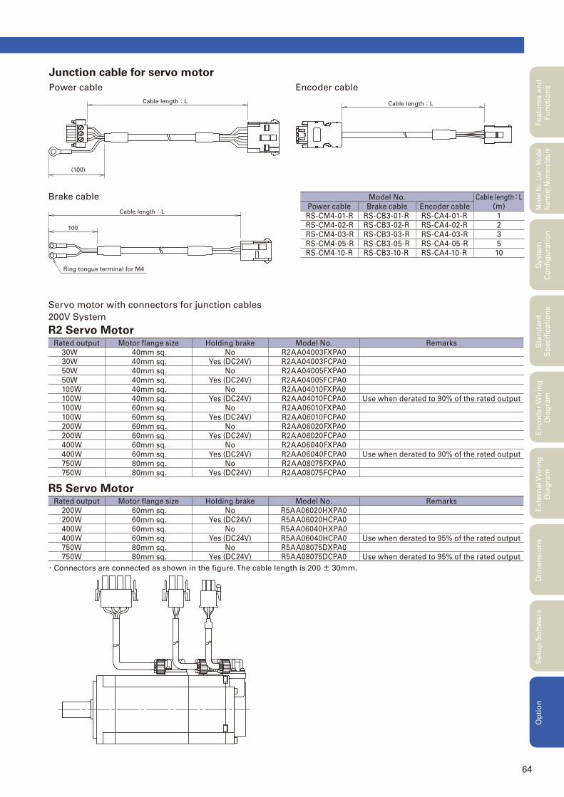
64
Junction cable for servo motor
Power cable
Brake cable
Encoder cable
Servo motor with connectors for junction cables
200V System
R2 Servo Motor
Cable length:L
(100)
Cable length:L
Ring tongue terminal for M4
100
Cable length:L
Rated output Motor fl ange size Holding brake Model No. Remarks
30W 40mm sq. No R2AA04003FXPA0
30W 40mm sq. Yes (DC24V) R2AA04003FCPA0
50W 40mm sq. No R2AA04005FXPA0
50W 40mm sq. Yes (DC24V) R2AA04005FCPA0
100W 40mm sq. No R2AA04010FXPA0
100W 40mm sq. Yes (DC24V) R2AA04010FCPA0 Use when derated to 90% of the rated output
100W 60mm sq. No R2AA06010FXPA0
100W 60mm sq. Yes (DC24V) R2AA06010FCPA0
200W 60mm sq. No R2AA06020FXPA0
200W 60mm sq. Yes (DC24V) R2AA06020FCPA0
400W 60mm sq. No R2AA06040FXPA0
400W 60mm sq. Yes (DC24V) R2AA06040FCPA0 Use when derated to 90% of the rated output
750W 80mm sq. No R2AA08075FXPA0
750W 80mm sq. Yes (DC24V) R2AA08075FCPA0
R5 Servo MotorRated output Motor fl ange size Holding brake Model No. Remarks
200W 60mm sq. No R5AA06020HXPA0
200W 60mm sq. Yes (DC24V) R5AA06020HCPA0
400W 60mm sq. No R5AA06040HXPA0
400W 60mm sq. Yes (DC24V) R5AA06040HCPA0 Use when derated to 95% of the rated output
750W 80mm sq. No R5AA08075DXPA0
750W 80mm sq. Yes (DC24V) R5AA08075DCPA0 Use when derated to 95% of the rated output
・Connectors are connected as shown in the fi gure. The cable length is 200± 30mm.
Model No. Cable length:L(m)Power cable Brake cable Encoder cable
RS-CM4-01-R RS-CB3-01-R RS-CA4-01-R 1
RS-CM4-02-R RS-CB3-02-R RS-CA4-02-R 2
RS-CM4-03-R RS-CB3-03-R RS-CA4-03-R 3
RS-CM4-05-R RS-CB3-05-R RS-CA4-05-R 5
RS-CM4-10-R RS-CB3-10-R RS-CA4-10-R 10
Featu
res a
nd
Fu
ncti
on
sM
odel
No.
Lis
t
・Mod
el
Num
ber
Nom
encl
atur
eS
tan
dard
S
pecifi
cati
on
sE
nco
der
Wir
ing
D
iag
ram
Exte
rnal W
irin
g
Dia
gra
mD
imen
sio
ns
Setu
p S
oft
ware
Op
tio
nS
yste
m
Co
nfi
gu
rati
on
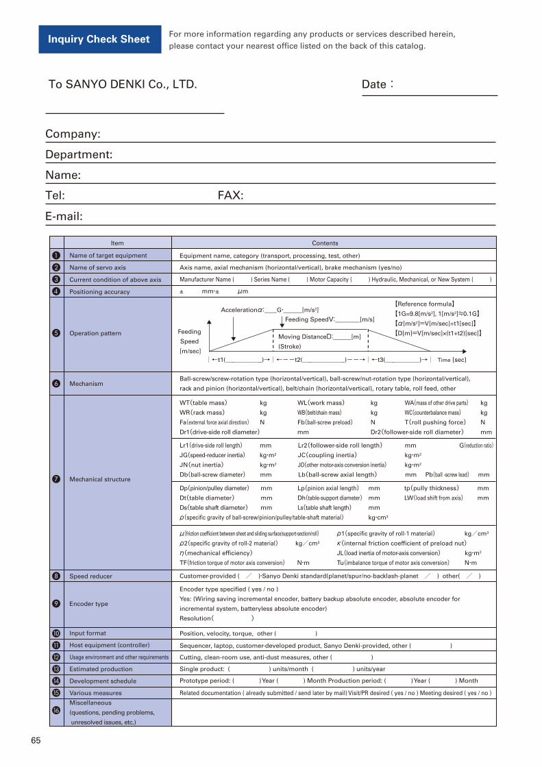
65
❶ Name of target equipment Equipment name, category (transport, processing, test, other)
❾ Encoder type
Encoder type specified ( yes / no )
Yes: (Wiring saving incremental encoder, battery backup absolute encoder, absolute encoder for
incremental system, batteryless absolute encoder)
Resolution( )
❷ Name of servo axis Axis name, axial mechanism (horizontal/vertical), brake mechanism (yes/no)
❸ Current condition of above axis Manufacturer Name ( ) Series Name ( ) Motor Capacity ( ) Hydraulic, Mechanical, or New System ( )
❹ Positioning accuracy ± mm・± μm
❺ Operation pattern
Accelerationα:__G・___[m/s2]
Feeding SpeedV:____[m/s]
Feeding
Speed
[m/sec]
【Reference formula】【1G=9.8[m/s2], 1[m/s2]≒0.1G】【α[m/s2]=V[m/sec]÷t1[sec]】【D[m]=V[m/sec]×(t1+t2)[sec]】
Moving DistanceD:___[m]
(Stroke)
❻ MechanismBall-screw/screw-rotation type (horizontal/vertical), ball-screw/nut-rotation type (horizontal/vertical),
rack and pinion (horizontal/vertical), belt/chain (horizontal/vertical), rotary table, roll feed, other
❼ Mechanical structure
WT(table mass) kg WL(work mass) kg WA(mass of other drive parts) kg
WR(rack mass) kg WB(belt/chain mass) kg WC(counterbalance mass) kg
Fa(external force axial direction) N Fb(ball-screw preload) N T(roll pushing force) N
Dr1(drive-side roll diameter) mm Dr2(follower-side roll diameter) mm
Lr1(drive-side roll length) mm Lr2(follower-side roll length) mm G(reduction ratio)JG(speed-reducer inertia) kg・m2 JC(coupling inertia) kg・m2
JN(nut inertia) kg・m2 JO(other motor-axis conversion inertia) kg・m2
Db(ball-screw diameter) mm Lb(ball-screw axial length) mm Pb(ball -screw lead) mm
Dp(pinion/pulley diameter) mm Lp(pinion axial length) mm tp(pully thickness) mm
Dt(table diameter) mm Dh(table-support diameter) mm LW(load shift from axis) mm
Ds(table shaft diameter) mm Ls(table shaft length) mm
ρ(specific gravity of ball-screw/pinion/pulley/table-shaft material) kg・cm3
μ(friction coefficient between sheet and sliding surface/support-section/roll) ρ1(specific gravity of roll-1 material) kg/cm3
ρ2(specific gravity of roll-2 material) kg/cm3 κ(internal friction coefficient of preload nut)η(mechanical efficiency) JL(load inertia of motor-axis conversion) kg・m2
TF(friction torque of motor axis conversion) N・m Tu(imbalance torque of motor axis conversion) N・m
❿ Input format Position, velocity, torque, other ( )
⓫ Host equipment (controller) Sequencer, laptop, customer-developed product, Sanyo Denki-provided, other ( )
⓭ Estimated production Single product: ( ) units/month ( ) units/year
⓮ Development schedule Prototype period: ( ) Year ( ) Month Production period: ( ) Year ( ) Month
Various measures Related documentation ( already submitted / send later by mail) Visit/PR desired ( yes / no ) Meeting desired ( yes / no )⓯
⓰Miscellaneous
(questions, pending problems,
unresolved issues, etc.)
⓬ Usage environment and other requirements Cutting, clean-room use, anti-dust measures, other ( )
❽ Speed reducer Customer-provided ( / )・Sanyo Denki standard(planet/spur/no-backlash-planet / ) other( / )
Item Contents
Time
Inquiry Check SheetFor more information regarding any products or services described herein,
please contact your nearest office listed on the back of this catalog.
Date:To SANYO DENKI Co., LTD.
Company:
Department:
Name:
Tel: FAX:
E-mail:

66
MEMO
CATALOG NO. S0944B006 ’13.10.IT
*For any question or inquiry regarding the above, contact our Sales Department.
■ Precautions For Adoption
Failure to follow the precautions on the right may cause moderate injury and property damage, or in some circumstances,could lead to a serious accident. Always follow all listed precautions.
■ ECO PRODUCTS
ECO PRODUCTS are designed with the goal
of lessening nevironmental impact, from
product development to disposal.
3-33-1, Minami-Otsuka, Toshima-ku,Tokyo 170-8451, Japan TEL: +81 3 5927 1020
TEL:
TEL:
TEL:
TEL:
TEL:
TEL:
TEL:
TEL:
*Remarks: Specifications are Subject to change without notice.


