29
Texas Instruments Accelerating China Auto growth - Functional safety solution in EV/HEV
Texas Instruments
Accelerating China Auto growth - Functional safety solution in EV/HEV

We help accelerate the future of automotive systems
Our products and system expertise
help you solve complex design
challenges to get electrified,
connected and automated cars to
market faster.
Commitment to long-term supply
System expertise Product innovation
7,000 automotive-qualified analog and embedded
products
350+ fully tested, circuit-based reference designs
Meets rigorous quality requirements, including IATF, ISO and OHSAS certifications
14 manufacturing sites worldwide
Proprietary processes and packaging
Proven track record of on-time delivery for product orders estimated ship date
Hundreds of new ICs introduced annually since
2014
Decades of advancing automotive electronics
150 automotive systems
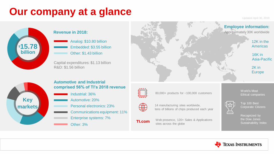
Our company at a glance
Revenue in 2018:
Analog: $10.80 billion
Capital expenditures: $1.13 billion
R&D: $1.56 billion
Embedded: $3.55 billion
Other: $1.43 billion
Automotive and Industrial
comprised 56% of TI’s 2018 revenue
Employee information:
Approximately 30K worldwide
12K in the
Americas
16K in
Asia-Pacific
2K in
Europe
$15.78 billion
Updated April 30, 2019
Key
markets
Industrial: 36%
Automotive: 20%
Personal electronics: 23%
Communications equipment: 11%
Enterprise systems: 7%
Other: 3%
14 manufacturing sites worldwide,
tens of billions of chips produced each year
80,000+ products for ~100,000 customers World’s Most
Ethical companies
Top 100 Best
Corporate Citizens
Recognized by
the Dow Jones
Sustainability Index Web presence, 120+ Sales & Applications
sites across the globe

Switches & multiplexers
Analog and embedded products for system design
Amplifier Data converter
Data converter
Embedded processing
Interface
Clock & timing
Protection ESD / EMI
Wireless connectivity
Voltage translation Logic
Buck DC/DC switching regulators
Boost, multichannel/ phase DC/DC
Linear power
Power switches, interface & lighting
High-voltage power
Battery management
Power management
Amplifier
Motor drives
Sensors
Temperature
Current
Humidity
Radar
Magnetic
Specialty
DLP® products
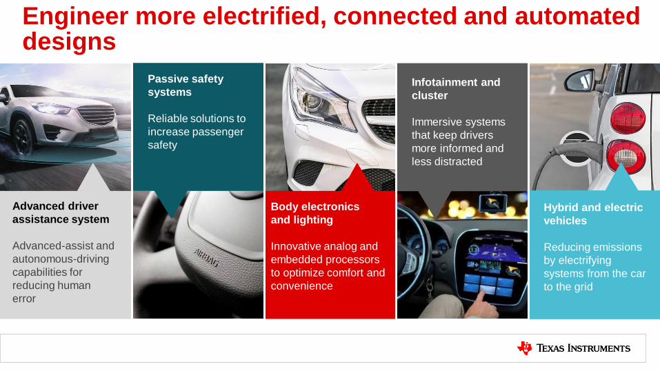
Engineer more electrified, connected and automated designs
Advanced driver
assistance system
Advanced-assist and
autonomous-driving
capabilities for
reducing human
error
Passive safety
systems
Reliable solutions to
increase passenger
safety
Body electronics
and lighting
Innovative analog and
embedded processors
to optimize comfort and
convenience
Infotainment and
cluster
Immersive systems
that keep drivers
more informed and
less distracted
Hybrid and electric
vehicles
Reducing emissions
by electrifying
systems from the car
to the grid

Advanced driver assistance systems
Camera
Sensor fusion LIDAR
Road to autonomy. Enable assisted,
automated driving features by
accelerating ADAS design for a safer,
less stressful driving experience.
Radar
Ultrasound

Infotainment & cluster systems
Cluster Display
Head unit Integrated cockpit
The next-generation digital cockpit.
Enable infotainment, display and V2X
systems that minimize distractions,
and help drivers stay informed and
connected to the world.
Telematics
Media interface Premium audio

Highest resolution >1 million pixels
Future-proof , V2X
Driver assistant
Programmable lighting technology
Dynamic lighting
BEL Solution - Innovative Lighting Enabled by DLP Technology
On-road symbol projections
ENHANCES DRIVER V IS IB IL ITY, MINIMIZE GLARE, AND COMMUNICATE W ITH L IGHT
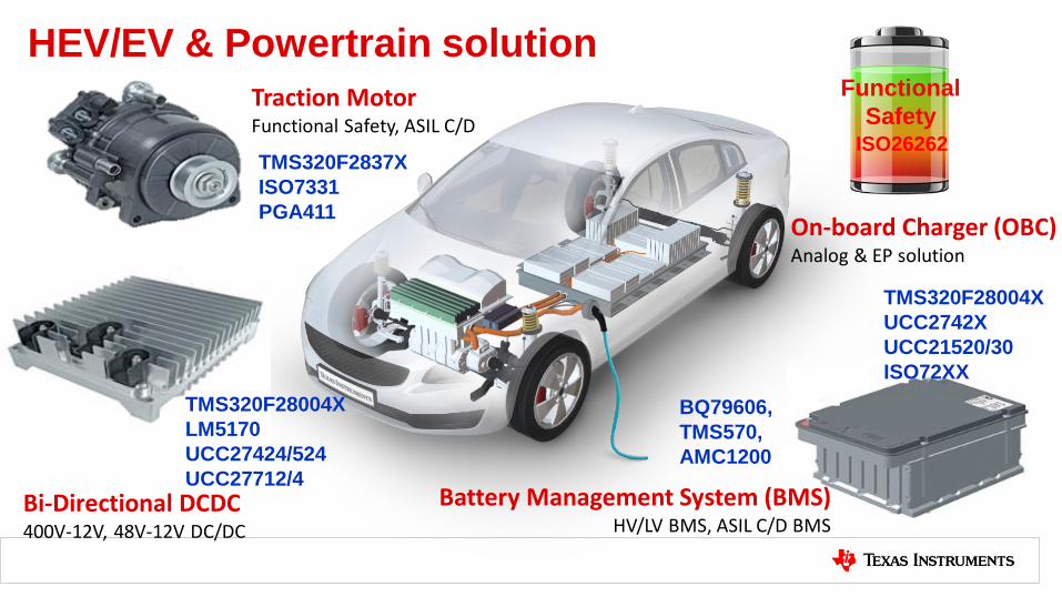
HEV/EV & Powertrain solution
Bi-Directional DCDC 400V-12V, 48V-12V DC/DC
Battery Management System (BMS) HV/LV BMS, ASIL C/D BMS
Traction Motor Functional Safety, ASIL C/D
On-board Charger (OBC) Analog & EP solution
BQ79606,
TMS570,
AMC1200
TMS320F2837X
ISO7331
PGA411
TMS320F28004X
LM5170
UCC27424/524
UCC27712/4
TMS320F28004X
UCC2742X
UCC21520/30
ISO72XX
Functional
Safety ISO26262

C2000™ @ FS Compliant OBC

EV/HEV power electronics: what does the market require?
Make the adoption of Electric Vehicles
easier for consumers (who expect the
same experience as ICE vehicles)
Faster time to market to
meet new EV
deployment goals around
the world
1 4 Reduce space and save
cost by combining power
electronic modules
5 Develop with advanced
power topologies in order
to maximize efficiency,
increase power density to
support larger batteries
and longer range per
charge.
2
Immediate need for customers to scale
their investment in EV designs to service
the needs of a complete EV model lineup
C2000 MCUs help customers achieve higher power
levels with best in class efficiency, increased power
density, and system robustness (safety)
Longer Range, faster charging, and
Lower overall vehicle cost
Safety critical robustness
and diagnostics need to
be re-thought to drive
system integration that
enables a safe and
secure driving experience
Lower development cost
by scaling platforms –
software reuse is vital
3

C2000 Differentiation for EV power electronics On-Board Battery Charger • Improve Power Density
• Support for GaN/SiC
• Advanced PFC Topologies for PFC
High Voltage DCDC • Improve Efficiency & EMI
• Zero Voltage Switching over wide load range (ex: PSFB >10% to higher)
• Phase-shedding methods for interleaving (ex: LLC improved over light load)
• Mode transition techniques with different switching patterns (Current to Voltage)
• Variable frequency control (frequency dithering)
Charging Station • High Power & Efficiency
• 3 Phase Vienna Rectifier or Totem Pole PFC
Traction Inverter • Improve Acceleration or Save Battery Life
• Integrate DC/DC Boost
• Fast current loop algorithms (3x current-loop bandwidth)
• Fast current loop algo (1/3 PWM frequency)
• Detect Motor Winding Faults • Motor Winding Fault Detection Algorithm (Kilby Labs)
• Back-up Virtual Resolver (lower-cost safety)
Compressor & Pumps • Save EV Battery Life & Time to Market
• InstaSPIN algorithm with low speed full torque (<500 rpm)
• Observer algorithm for high speed heavy load
Power Conversion
Motor Control

Electric Vehicle (EV) trends
Increasing Real-time Performance for Motor Control and Digital Power
Incre
asin
g H
ost
MC
U r
eq
uir
em
en
ts
System Requirements Real-Time Control Implications
Diverging requirements for Host MCU and Real-Time Control demands driving the
need to adopt separate MCU’s for each. Both vectors are increasing!
System Requirements
Customer
Functional Safety +
HOST MCU
Requirements
Customer
Performance
Requirements
Real-time MCU
Requirements

Real-time control performance increasing
Increasing Real-time Performance for Motor Control and Digital Power
Incre
asin
g H
ost
MC
U r
eq
uir
em
en
ts
System Requirements
• Increasing Motor Speed • Increasing System Efficiency
• Increasing Power Density
• Consolidating Control Functions
• Safe-ing Control Functions
• Increasing ASIL Levels
• Increasing I/O for Housekeeping
• Increasing AutoSAR overhead
• Advanced security standards
(EVITA, SHE)
• Advanced Communication
requirements
Real-Time Control Implications
Higher MIPS and control loop requirements Advanced control techniques and topologies for
high power applications requiring higher MIPS and
Control Peripherals Increasing Switching Frequency using SiC/GaN
FET’s
Multiple and emerging control functions required
(e.g. OBC+DCDC, motor + DCDC, traction boost)
Application-specific safety mechanisms
System Requirements
Higher MIPS, safety mechanisms
Higher pin count packages and Flash
Increased flash/RAM needs w/overhead
New accelerators, increased RAM
New peripherals, increased RAM
Housekeeping MCU Implications
General-purpose MCUs lack optimized real-time control architecture and peripherals/performance for realizing
advanced real-time control.
General Purpose MCUs lack needed control features:
integrated fast SAR ADC for sampling current and voltage,
high-resolution PWMs on duty, dead-band, and period to
drive SiC (>500kHz), slope compensation features,
delayed trip, windowed comparator subsystems for OV,
UV, OC, UC conditions, valley switching, and dedicated
safety mechanisms for ADC and PWM protection
To complement the host MCU,
either a scalable C2000™
controller, or an expensive FPGA
will have to be used.
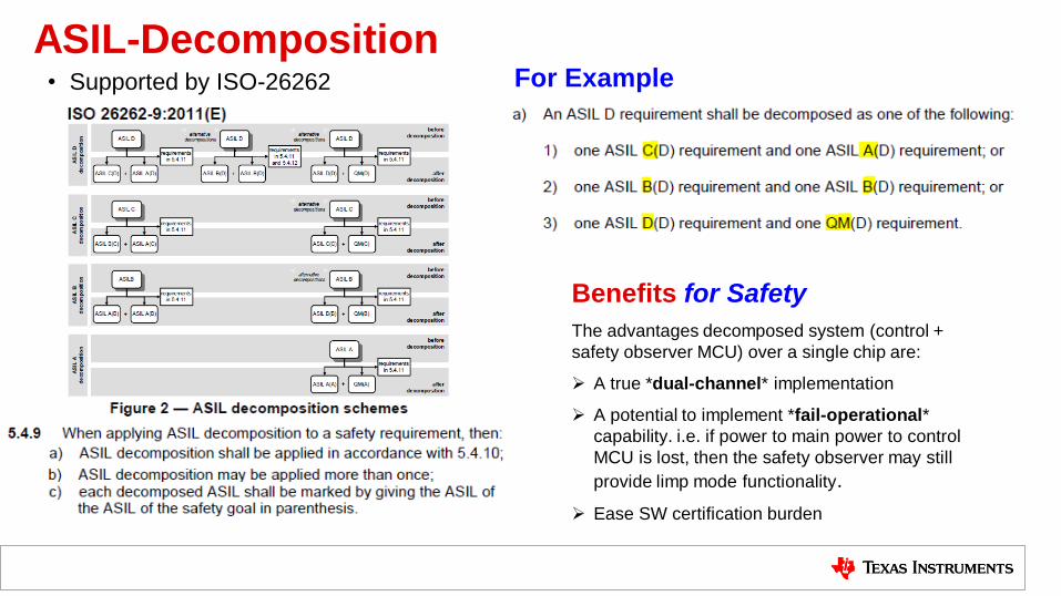
ASIL-Decomposition • Supported by ISO-26262
For Example
Benefits for Safety
The advantages decomposed system (control +
safety observer MCU) over a single chip are:
A true *dual-channel* implementation
A potential to implement *fail-operational*
capability. i.e. if power to main power to control
MCU is lost, then the safety observer may still
provide limp mode functionality.
Ease SW certification burden

C2000 F28004x
F28004x Actuation
8x ePWM Modules
16x Outputs (16x High-Res)
Fault Trip Zones
2x 12-bit DAC
Connectivity
3x UART
2x I2C (1x true PMBus)
2x SPI
FSI (Fast Serial Interface)
2x CAN 2.0B
Sensing
ADC1: 12-bit, 3.5 MSPS, 8ch
ADC2: 12-bit, 3.5 MSPS, 8ch
ADC3: 12-bit, 3.5 MSPS, 8ch
7x Windowed Comparators w/ Integrated
12-bit DAC
7x PGAs
4x Sigma Delta Channels
(2x Filters per channel)
Temperature Sensor
2x eQEP
7x eCAP (2x HRCAP)
Power & Clocking
2x 10 MHz OSC
4-20 MHz Ext OSC Input
1.2V VREG
POR/BOR Protection
System Modules
3x 32-bit CPU Timers
NMI Watchdog Timer
192 Interrupt PIE
Memory
Up to 256 kB Flash +ECC
Up to 100 kB SRAM +parity
2x 128-bit Security Zones
Boot ROM
InstaSPIN™ Motor ROM Debug
cJTAG / Real-time JTAG
CLA core
100 MHz
FPU
Processing
C28x™ DSP core
100 MHz
FPU
TMU
VCU-I
6ch DMA
CRC
Adv. IP
Production Now:
http://www.ti.com/product/TMS320F280049
Package Dimension
56-pin QFN 7x7mm
64-pin LQFP 12x12mm
100-pin LQFP 16x16mm
Packages
Configurable Logic Block
4 Tiles
Temperatures 125C Q100
Optimized for Power Control Applications
Streamlined performance and power
• 100 MHz / 256 kB flash / 100 kB SRAM
• Floating Point and Trigonometric Math Unit
• Next Generation CLA; support for continuous background task
• 60% lower power consumption vs. F2806x + DC-DC option
Advanced actuation and design flexibility
• 4th gen ePWM enables implementation of the most advanced switching techniques for increased efficiency and power density
• Enhanced crossbars provide flexibility in combining inputs, outputs and internal resources for most advanced control and protection mechanisms
Integrated analog and protection
• 3 12-bit 3.45MSPS ADC with post processing and threshold actions
• 7 on-chip PGA(3/6/12/24) with post gain filtering and bypass option
• 7 Windowed Comparators + 2 12-bit output DACs
• 4 Sigma Delta Demodulation Channels
Differentiation
F28004x Experimenter’s Kit
Part Number: TMDSCNCD280049C
http://www.ti.com/tool/TMDSCNCD280049C
F28004x LaunchPad
Part Number: LAUNCHXL-F280049C
http://www.ti.com/tool/LAUNCHXL-F280049C
Tools
Application SDKs
C2000Ware™ Software Package
SafeTI IEC60730
Software

C2000 Functional safety overview • C2000 Automotive MCUs are:
– Developed using an ISO 26262 compliant HW development process that is independently assessed (by TUV-SUD) to meet systematic capability of ASIL-D
• Download TUV-SUD certificate
– F28004x and F2807x/37x have over 300 safety mechanisms described in functional safety manuals: (overview of C2000 Functional Safety Mechanisms)
• Download F28004x Functional Safety Manual • Download F2807x/37x Functional Safety Manual
– SafeTI™ Diagnostics Libraries: SW that accelerates designing for functional safety applications (available for F2807x/37x).
• (Free) Access may be requested at: http://www.ti.com/tool/C2000-SAFETI-DIAGNOSTICS-LIB
– Access tunable FMEDA with 5-part video training on how to tune FMEDA for your system
• Request FMEDA access at: http://www.ti.com/lit/ug/spruic8b/spruic8b.pdf
• FMEDA Tuning Video training at: https://training.ti.com/c2000-safeti-tunable-fmeda-training
– C28x and CLA Compiler Qualification kit assists customers in qualifying their use of the TI C2000/CLA C/C++ Compiler to ISO 26262:
• http://www.ti.com/tool/safeti_cqkit
– C2000 MCUs are supported by Mathworks Simulink and embedded coder – learn more
All available on the web at:
www.ti.com/c2000safeti
Overview of C2000 Functional Safety Mechanisms

Streamline your system safety certification
http://www.ti.com/lit/an/spracc0/spracc0.pdf
http://www.ti.com/lit/an/spraci3/spraci3.pdf
http://www.ti.com/lit/an/spraci7/spraci7.pdf
Error Detection in SRAM
http://www.ti.com/lit/an/spraca7/spraca7.pdf
http://www.ti.com/lit/an/spracb9/spracb9.pdf
C2000™ Memory Power-On Self-Test (M-POST)
C2000™ Hardware Built-In Self-Test
C2000™ CPU Memory Built-In Self-Test
C2000™ CLA Self-Test Library
Detailed application reports available on ti.com:
http://www.ti.com/lit/wp/swry027/swry027.pdf
Achieving Coexistence of Safety Functions
for EV/HEV Using C2000™ MCUs
http://www.ti.com/lit/wp/sway028/sway028.pdf
An introduction to ASIL decomposition and SIL synthesis

Variable DC Bus to optimize DC-DC converters
120/220 Vrms 400-600V
(variable bus to
optimize LLC converter)
At resonance
operation
LLC converters when operating away from resonance have high circulating currents and hence lower efficiency during that
operation.
As the battery voltage varies widely, a variable PFC link voltage concept can increase the region of operation at resonance
and thus improve efficiency
PFC efficiency will degrade but not significantly, specially if CRM mode PFC is used efficiency drop will be very low owing
to ZVS operation. Even for CCM PFC efficiency drop from 400V to 600V is around 0.3% with SiC based design.
Vprim
380V
600V
280V
Vsec451.4V
1.33:1
285V

Demonstrating integrated HV Traction + DC/DC (CES 2019)
HV DCDC (400-12V) + 60kW HV Traction
Inverter on single C2000 Real-Time
Controller
Formula 1: 150kW HV Traction Inverter +
400-48V DCDC >400kHz PWM switching with
GaN on single C2000 Real-Time Controller in
tight form factor
Video link
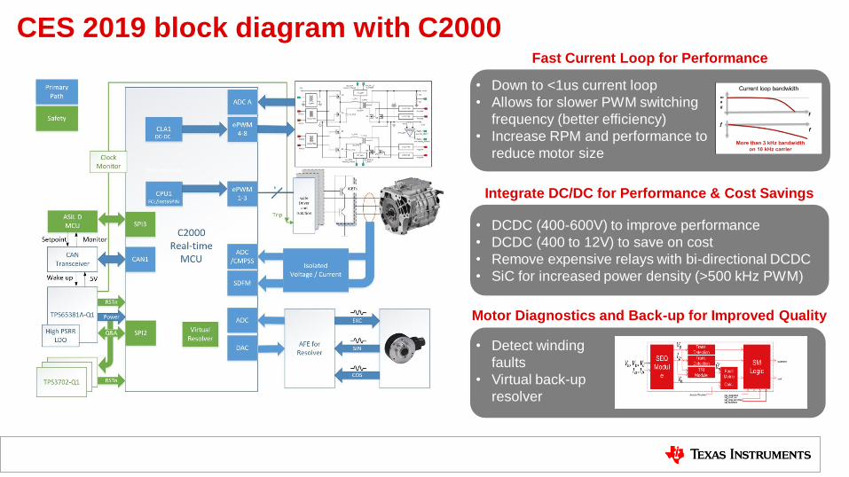
Fast Current Loop for Performance
• Down to <1us current loop
• Allows for slower PWM switching
frequency (better efficiency)
• Increase RPM and performance to
reduce motor size
• Detect winding
faults
• Virtual back-up
resolver
Motor Diagnostics and Back-up for Improved Quality
• DCDC (400-600V) to improve performance
• DCDC (400 to 12V) to save on cost
• Remove expensive relays with bi-directional DCDC
• SiC for increased power density (>500 kHz PWM)
Integrate DC/DC for Performance & Cost Savings
CES 2019 block diagram with C2000

Integrated traction inverter proposal • Opportunity to reduce cost with ASIL D
Decomposition Architecture:
• ASIL-D(D) = ASIL-B(B) + ASIL-B(D)
• ASIL-B MCU lower cost
• Lower cost of ASIL-B AUTOSAR license
• C2000 being certified for device level ASIL-B
• Reduce Bill Of Material
• Integrate CPLD with expanded CLB-enabled
C2000 devices
• Leverage lower cost C2000 devices
• Opportunity to integrate digital power into one
mechanical box
• DCDC (400-12V) + Traction
• OBC + DCDC + Traction
• DCDC Boost (400-600V) + Traction
• Opportunity to Increase Motor Performance &
Efficiency
• Dual Motors
• Motor Speed (>20k rpm)
• DCDC Boost removes back EMI techniques
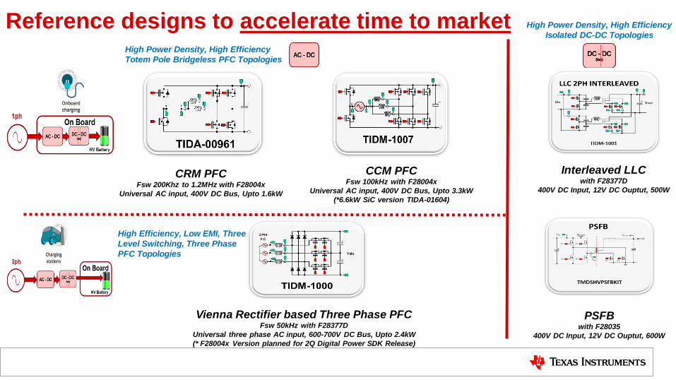
Reference designs to accelerate time to market High Power Density, High Efficiency
Totem Pole Bridgeless PFC Topologies
CRM PFC
Fsw 200Khz to 1.2MHz with F28004x
Universal AC input, 400V DC Bus, Upto 1.6kW
CCM PFC Fsw 100kHz with F28004x
Universal AC input, 400V DC Bus, Upto 3.3kW
(*6.6kW SiC version TIDA-01604)
Vienna Rectifier based Three Phase PFC Fsw 50kHz with F28377D
Universal three phase AC input, 600-700V DC Bus, Upto 2.4kW
(* F28004x Version planned for 2Q Digital Power SDK Release)
High Efficiency, Low EMI, Three
Level Switching, Three Phase
PFC Topologies
Interleaved LLC with F28377D
400V DC Input, 12V DC Ouptut, 500W
PSFB with F28035
400V DC Input, 12V DC Ouptut, 600W
High Power Density, High Efficiency
Isolated DC-DC Topologies

• Interleaved, 3.3-kW, Single-Phase, Bridgeless CCM Totem Pole PFC Stage
using GaN
• 100-kHz Pulse Width Modulation (PWM) switching
• Programmable Output Voltage, 380-V DC Nominal
• Greater than 98% peak efficiency
• Less than 2% Total Harmonic Distortion (THD)
• poweSUITE support enables easy adaptation of software
• High power density design
• High performance C2000™ controller enables superior control and enables
advanced control scheme to be implemented such as
Soft starting for totem pole bridge
Phase shedding to enable higher efficiency
Non Linear control loop to reduce voltage spikes
Adaptive deadtime for improved efficiency
Input cap PF loss compensation
http://www.ti.com/tool/tidm-1007
Features & Benefits
98.73% Efficiency, 3.3kW GaN based CCM Totem Pole PFC reference design for HEV & EV chargers/ Reference design: TIDM-1007

Size: 235mm X 85mm X 85mm
98.75% Efficiency, 6.6kW SiC based CCM Totem Pole PFC reference design for HEV & EV chargers Reference design: TIDA-01604
Measured Efficiency (vs) Load
Measured Waveforms
Vin=240Vac, Pout=6.6kW
Features & Benefits
• Interleaved, 6.6-kW, single-phase, bridgeless CCM totem pole
PFC stage using SiC
• 100-kHz Pulse Width Modulation (PWM) switching
• Variable output voltage for optimizing DC/DC stage efficiency,
400-600V DC
• Greater than 98% peak efficiency
• Less than 2% Total Harmonic Distortion (THD)
• High power density design
• High performance C2000™ controller enables superior control
and enables advanced control scheme to be implemented
• High Common Mode Transient Immunity (CMTI) of >100V/ns
http://www.ti.com/tool/tidm-01604

• TI Devices: TMS320F280049C, UCC21521, ISO7721-
Q1,AMC1311-Q1, OPA320, LMV116MF,
SN6505BDBVR, TPS7B6950QDCYRQ1
• On Board Chargers,
• Off Board Chargers
• Grid Storage
Bi-Directional CLLLC Resonant Dual Active Bridge (DAB) Reference design for HEV/EV onboard charger
• Type 4 PWM with Hi-Resolution on C2000 MCU enable
high frequency resonant converters control.
• CMPSS, X-Bar and PWM enable active synchronous
rectification for better efficiency.
• CLA enables integrated OBC with AC-DC and DC-DC
controlled using one MCU
• SFRA enables quick verification of control design on
resonant converters where mathematical model is not
known
• V1: 400-600V DC (HV-Bus voltage/ PFC output)
• V2: 280-450V (battery)
• Power Level: 6.6kW
• CLLC symmetric tank capable of bi-directional operation
• Soft switching, across load, close to resonance operation
achieves high efficiency, 98% Efficiency
• Snubber less design enables higher density
• Switching Frequency 500kHz nominal, 300-700kHz
range
• Active synchronous rectification scheme implemented
using Rogowski coil based current sensor
• Power Density of 40W/inch^3
Features Benefits
Applications
Tools & Resources

Simplify your most demanding design challenges and speed
time to market.
Texas Instruments accelerates the future of automotive systems
www.TI.com/Automotive
As a trusted leader in automotive reliability, efficiency
and technical know-how, TI helps developers accelerate
the
future of automotive systems
Your trusted partner for quality products with a continual
supply.
Fuel your innovation with our analog and embedded
processing products.

On-Board(OBC) & Wireless charger TI Home > Applications > Automotive > Hybrid, Electric & Power Train Systems > On-Board(OBC) & Wireless Charger
Different
Variants
Subsystems
(clickable)
Product/Design
Proposals

Thanks!


