ACCEPTED TO IEEE TRANSACTIONS ON SMART GRID, APRIL 2014 1 Stability Analysis of Unbalanced Distribution Systems With Synchronous Machine and DFIG Based Distributed Generators Ehsan Nasr-Azadani, Student Member, IEEE, Claudio Ca˜ nizares, Fellow, IEEE, Daniel Olivares, Student Member, IEEE, and Kankar Bhattacharya, Senior Member, IEEE Abstract—There are many technical aspects and challenges in distributed generation (DG) that have not been properly understood and addressed so far. Distribution systems cannot be considered as balanced three-phase systems, because these are inherently unbalanced in steady-state operation. A full character- ization of the unbalanced system with respect to system stability allows a better understanding of the dynamic behaviour of such systems. This paper presents a comprehensive investigation of the effects of system unbalance on the stability of the distribu- tion systems with synchronous generator (SG) and doubly-fed induction generator (DFIG) based DG units at different loading levels. Detailed steady-state and dynamic analyses of the system are performed. Based on classical voltage, small-perturbation and transient stability studies, it is demonstrated that system unbalance can significantly affect the distribution system dynamic performance, in ways that have not been discussed in the technical literature so far. A simple and effective control strategy based on an Unbalanced Voltage Stabilizer (UVS) is also proposed to improve the system control and the stability of unbalanced distribution systems with SG and DFIG. Eigenvalue analyses and time-domain simulations demonstrate the effectiveness of the proposed UVS for unbalance conditions. Index Terms—Stability studies, unbalanced power systems, distributed generation, doubly-fed induction generator, voltage control. I. I NTRODUCTION S INCE the beginning of the 1990s, there has been sig- nificant growth of distributed generation (DG), driven by environmental and economic factors resulting in significant penetration of small scale generation at the distribution sys- tem level. Penetration of DGs in distribution systems make them active systems, instead of passive. This can affect the dynamics of the whole power system, and especially of the distribution system. Although DGs may have some benefits for the system such as improvements in system reliability, there are many technical aspects and challenges that are still not properly understood or addressed. Among the numerous issues associated with distribution systems containing DGs, stability analysis is of significant interest (e.g., [1]–[3]). This work was supported by the NSERC Smart Microgrids Strategic Network (NSMG-Net) (www.smart-microgrid.ca) and an NSERC Discovery grant. E. Nazr-Azadani, C. Ca˜ nizares, and K. Bhattacharya are with the De- partment of Electrical and Computer Engineering, University of Water- loo, Waterloo, ON, Canada, N2L 3G1 (email: [email protected], [email protected], [email protected]). D. Olivares is with the Department of Electrical Engineering, Pontifical Catholic University, Santiago, Chile (email: [email protected]). Although some stability studies of distribution systems with DGs have been reported in the literature, a detailed and systematic analysis considering distribution systems under unbalanced conditions has not been sufficiently addressed. A majority of stability studies reported in the literature are based on approaches similar to those used in transmission systems, and thus several simplifications, in particular the assumption of balanced conditions, are applied. However, distribution systems cannot be considered to be balanced three-phase systems, since these are inherently unbalanced in steady-state. A full characterization of the unbalanced system in stability analyses would allow a better understanding of its dynamic behaviour. Nowadays, in several countries, many DGs are small syn- chronous generators (SGs) connected to low voltage distri- bution systems [4], [5]. For example, there is a significant potential for cogeneration based on small SGs from sugar- cane facilities in Brazil [4]. Across Canada, many remote communities operate microgrids supplied mostly from diesel- fired SGs [6]. On the other hand, wind energy is one of the most promising renewable energy sources, with the de- mand for connecting wind generators to distribution systems being on the rise. Among different types of wind turbine technologies, doubly fed induction generators (DFIGs) have the largest world market share of wind turbine generators [7], offering several advantages compared to fixed-speed genera- tors, including its ability to provide variable speed operation in a cost-effective way and independent active and reactive power control capabilities. Since the application of these DGs in distribution systems may result in different issues such as electromechanical oscillations, understanding the dynamic behaviour of SGs and DFIGs under unbalanced conditions in a distribution system is of interest to many utilities and grid operators. A few reported studies consider the characteristics of dis- tribution systems in stability analyses taking into account unbalanced loads and lines. In [8], a continuation three-phase power flow approach in polar coordinates is presented for voltage stability analysis under unbalanced conditions; this approach is based on static power flow equations of a three- phase model to obtain PV curves. In [9], voltage stability studies are presented using a three-phase constrained optimal power flow which seeks to maximize the loading factor. Since these studies are based on static power flows, the impact of system dynamics on voltage stability is not fully investigated.
Transcript
ACCEPTED TO IEEE TRANSACTIONS ON SMART GRID, APRIL 2014 1
Stability Analysis of Unbalanced DistributionSystems With Synchronous Machine and DFIG
Daniel Olivares, Student Member, IEEE, and Kankar Bhattacharya, Senior Member, IEEE
Abstract—There are many technical aspects and challengesin distributed generation (DG) that have not been properlyunderstood and addressed so far. Distribution systems cannotbe considered as balanced three-phase systems, because these areinherently unbalanced in steady-state operation. A full character-ization of the unbalanced system with respect to system stabilityallows a better understanding of the dynamic behaviour of suchsystems. This paper presents a comprehensive investigation ofthe effects of system unbalance on the stability of the distribu-tion systems with synchronous generator (SG) and doubly-fedinduction generator (DFIG) based DG units at different loadinglevels. Detailed steady-state and dynamic analyses of the systemare performed. Based on classical voltage, small-perturbationand transient stability studies, it is demonstrated that systemunbalance can significantly affect the distribution system dynamicperformance, in ways that have not been discussed in thetechnical literature so far. A simple and effective control strategybased on an Unbalanced Voltage Stabilizer (UVS) is also proposedto improve the system control and the stability of unbalanceddistribution systems with SG and DFIG. Eigenvalue analysesand time-domain simulations demonstrate the effectiveness ofthe proposed UVS for unbalance conditions.
Index Terms—Stability studies, unbalanced power systems,distributed generation, doubly-fed induction generator, voltagecontrol.
I. INTRODUCTION
S INCE the beginning of the 1990s, there has been sig-nificant growth of distributed generation (DG), driven by
environmental and economic factors resulting in significantpenetration of small scale generation at the distribution sys-tem level. Penetration of DGs in distribution systems makethem active systems, instead of passive. This can affect thedynamics of the whole power system, and especially of thedistribution system. Although DGs may have some benefits forthe system such as improvements in system reliability, thereare many technical aspects and challenges that are still notproperly understood or addressed. Among the numerous issuesassociated with distribution systems containing DGs, stabilityanalysis is of significant interest (e.g., [1]–[3]).
This work was supported by the NSERC Smart Microgrids StrategicNetwork (NSMG-Net) (www.smart-microgrid.ca) and an NSERC Discoverygrant.
E. Nazr-Azadani, C. Canizares, and K. Bhattacharya are with the De-partment of Electrical and Computer Engineering, University of Water-loo, Waterloo, ON, Canada, N2L 3G1 (email: [email protected],[email protected], [email protected]).
D. Olivares is with the Department of Electrical Engineering, PontificalCatholic University, Santiago, Chile (email: [email protected]).
Although some stability studies of distribution systemswith DGs have been reported in the literature, a detailedand systematic analysis considering distribution systems underunbalanced conditions has not been sufficiently addressed. Amajority of stability studies reported in the literature are basedon approaches similar to those used in transmission systems,and thus several simplifications, in particular the assumptionof balanced conditions, are applied. However, distributionsystems cannot be considered to be balanced three-phasesystems, since these are inherently unbalanced in steady-state.A full characterization of the unbalanced system in stabilityanalyses would allow a better understanding of its dynamicbehaviour.
Nowadays, in several countries, many DGs are small syn-chronous generators (SGs) connected to low voltage distri-bution systems [4], [5]. For example, there is a significantpotential for cogeneration based on small SGs from sugar-cane facilities in Brazil [4]. Across Canada, many remotecommunities operate microgrids supplied mostly from diesel-fired SGs [6]. On the other hand, wind energy is one ofthe most promising renewable energy sources, with the de-mand for connecting wind generators to distribution systemsbeing on the rise. Among different types of wind turbinetechnologies, doubly fed induction generators (DFIGs) havethe largest world market share of wind turbine generators [7],offering several advantages compared to fixed-speed genera-tors, including its ability to provide variable speed operationin a cost-effective way and independent active and reactivepower control capabilities. Since the application of these DGsin distribution systems may result in different issues suchas electromechanical oscillations, understanding the dynamicbehaviour of SGs and DFIGs under unbalanced conditions ina distribution system is of interest to many utilities and gridoperators.
A few reported studies consider the characteristics of dis-tribution systems in stability analyses taking into accountunbalanced loads and lines. In [8], a continuation three-phasepower flow approach in polar coordinates is presented forvoltage stability analysis under unbalanced conditions; thisapproach is based on static power flow equations of a three-phase model to obtain PV curves. In [9], voltage stabilitystudies are presented using a three-phase constrained optimalpower flow which seeks to maximize the loading factor. Sincethese studies are based on static power flows, the impact ofsystem dynamics on voltage stability is not fully investigated.
ACCEPTED TO IEEE TRANSACTIONS ON SMART GRID, APRIL 2014 2
There are recent studies of the effect of unbalanced condi-tions on small-perturbation stability of SGs. Thus, in [10] and[11], the effect of unbalanced conditions on damping factorsand frequency is investigated. In [10], a model-based approachin the phasor domain for small-perturbation stability analysisof unbalanced distribution systems is presented, and a modelidentification technique for small-perturbation stability studiesare presented in [11]. However, in these papers, the effects ofunbalanced conditions under high loading levels, which wouldtypically lead to instability, are not studied.
Simplified models of synchronous and induction machineshave been developed for transient stability studies of unbal-anced power systems [12]–[15]. These models represent thefundamental frequency component of the machine behaviorand neglect the harmonic components. Based on these models,some authors analyze the impacts of DGs on transient stability.Thus, in [16] and [17], the impact of induction generators ontransient stability is studied, and [18] addresses the impactof DG on transmission systems transient stability, whereinincreasing the DG penetration level is matched by a reductionin centralized power generation, which consequently resultsin a reduction in the total amount of rotating mass andreactive power support in the system. Most of the existingtransient stability studies with DGs consider different faulttypes under balanced loading conditions. For example, briefstudies on transient stability analysis of a distribution systemwith selected DG units based on the calculation of criticalclearing time (CCT) are presented in [3] and [19]. However,the impact of load unbalancing on transient stability studieshas not been properly studied.
Control and stability studies of DFIGs have been discussedin the last decade for balanced operation [20]–[24]. However,if voltage unbalance is not properly compensated by systemcontrols, the stator current can be highly unbalanced evenwith a small unbalanced stator voltage. In such case, the mainproblem is that high current, torque, and power oscillationsappear at double the electrical frequency due to the negativesequence components, resulting in disconnection [25]–[27].Techniques have been proposed to mitigate these oscillations,based on the injection of negative sequence components,considering rotor-side [26] or grid-side converters [25], [27].In [28], an approach based on a disturbance rejection controlleris presented to compensate oscillations using a feed-forwardcomponent of the current controllers. In [29], a stand-aloneDFIG under unbalanced conditions is studied, with the gridconverter supplying reactive power to compensate for theunbalanced grid voltage. A small signal stability analysis ofa DFIG wind turbine is presented in [30]. In all these papers,the effects of unbalanced conditions under high loading levels,which would typically lead to instability, are not studied.
Based on the aforementioned shortcomings identified in theexisting technical literature, comprehensive studies consider-ing the dynamic behaviour of SG and DFIG based DGs underunbalanced conditions in distribution systems are presentedhere. This is an issue for some utilities (e.g., Hydro OneRemote Communities, in Ontario, Canada), who have specialinterest on the stability analyses of unbalanced distributionsystems with SG and DFIG DGs, since some of their feeders
present unbalances as high as 25% per phase under certainconditions. Therefore, this paper presents, for the first time,comprehensive studies on voltage, small-perturbation, andtransient stability of unbalanced distribution systems with SGand DFIG based DGs. Both dynamic and static voltage stabil-ity analyses are carried out using three-phase PV curves andmaximum system loadability, and transient stability studies areperformed using time domain simulations of contingenciesunder various unbalanced conditions, based on three-phasedetailed models. Small-perturbation stability studies are car-ried out using a model identification approach to computeeigenvalues and thus study the impact of load unbalancingin heavily loaded systems. Finally, control strategies based onsimple and easy to implement Unbalanced Voltage Stabilizers(UVSs) are proposed to improve the stability of unbalanceddistribution systems with DGs, using time-domain simulationsto demonstrate their effectiveness. Hence, the main contribu-tions of the paper can be summarized as follows:
• A new application of three-phase power flow and dy-namic voltage stability using time domain simulations ispresented. A static three-phase power flow with properDG models for voltage stability studies is used to deter-mine maximum system loadbility under various unbal-anced conditions.
• The application of an identification approach, based onProny and Steiglitz-McBride iteration methods, for small-perturbation stability studies of unbalanced systems withDGs is proposed. This method provides a frameworkfor small-perturbation stability analysis of unbalancedsystems with DGs.
• A comprehensive evaluation of voltage stability, eigen-value analyses, and time domain simulations for a typicaldistribution system with SG and DFIG based-DGs ispresented under various unbalanced conditions.
• Existing control techniques to compensate the negativeimpact of unbalanced operation of DFIGs are demon-strated to be ineffective at heavily loaded conditions.Furthermore, simple and effective control strategies basedon voltage unbalance for both SG and DFIG based-DGsare proposed to improve the stability of the distributionsystems. The simplicity of the proposed UVS makes itpractical and relatively easy to implement in real systems.
The rest of paper is organized as follows: A brief overviewof the system model and the methodology used for stabilityanalyses under unbalanced conditions are presented in SectionII; the proposed unbalanced voltage stabilizer control is alsodiscussed in this section. In Section III, comprehensive numer-ical results with different scenarios for a DG-load-grid systemare presented and discussed. Finally, Section IV highlights themain contributions and conclusions of the paper.
II. SYSTEM MODELING, ANALYSIS AND CONTROLMETHODOLOGY
A. SG and Network Models
Detailed representation of the SG model is used for the sim-ulations and studies [31]; hence, three-phase stator and rotorwindings in the dqo reference-frame are used [32]. Since small
ACCEPTED TO IEEE TRANSACTIONS ON SMART GRID, APRIL 2014 3
SG based DGs are very likely to have simple Proportional-Integral (PI) voltage regulators, Automatic Voltage Regulators(AVRs) Type IV (AC4A) are used here. Moreover, the type ofvoltage feedback in the excitation system affects the dynamicbehavior of the system [33], a typical voltage feedback repre-sented by the average value of the voltage magnitude for eachphase is used in this paper [31].
Lines are modeled as constant coupled impedance branches,and loads are treated as constant impedances as well. There-fore, the following loading factor l is defined to model loadimpedance Zl increases in each phase, which increase theactive and reactive power demand:
Zl =Zφl
(1)
where Zφ is the base-load impedance for each phase. A loadunbalance factor is defined to analyze different scenarios ofunbalance as the load varies [10]. Thus, as the impedanceof the load in one phase is increased, the load impedancein another phase is decreased, so that total impedance of thethree-phase load remains constant in all cases, as follows:
Zal = (1 + k)Zl (2)
Zbl = Zl (3)
Zcl = (1− k)Zl (4)
where k is the load unbalance factor, and Zal, Zbl, and Zclare the phase impedances of the load.
B. DFIG Model
The DFIG is modeled using a classical and detailed induc-tion machine model with a wound rotor [32], and a detailedmodel of the back-to-back ac/ac converter controlling the rotor[34]. Unbalance loading in DFIGs introduce negative sequencecomponents in the voltage, current, and flux, which can resultin significant oscillations in torque, active and reactive powerwith a double frequency; hence, a DFIG model that considersthe positive and negative sequence components is needed tostudy this phenomenon. This is accomplished using a three-phase signal in the stationary αβ reference-frame expressedby the positive and negative sequence components as follows:[
Fα(t)Fβ(t)
]=
[F+α (t) + F−
α (t)F+β (t) + F−
β (t)
](5)
= F+αβe
j(ωet) + F−αβe
−j(ωet)
where F represents voltage, current, or flux linkage; t istime; and ωe is electrical angular frequency. There are twoapproaches for the positive and negative sequence componentsseparation under unbalanced conditions: separation by lowpass filter (LPF), and separation by a signal delay cancellation[27]. In this paper, the positive and negative sequence compo-nents separation is based on a LPF approach, in which, as thenegative sequence components appear with the frequency 2ωein the positive dq reference-frame, and the positive sequenceappears with the frequency 2ωe in the negative dq reference-frame, a LPF can be used to bypass dc components for bothsequences. Thus, the stator components (i.e., current, voltage,
and flux) in the positive and negative sequence αβ reference-frame yield:
F+αβ = F+
dq + F−dqe
−j2ωet (6)
F−αβ = F−
dq + F+dqe
−j2ωet
The d-axis for the positive sequence in the dq reference-frame is fixed to the positive sequence of stator flux rotatingat the speed ωe, while the d-axis for the negative sequencerotates at −ωe. Based on two rotating reference-frames at ωeand −ωe, the voltage equations for the positive and negativesequences at the grid side can be written as:
v+gdq − v+cdq = (Rg + jωeLg)i
+gdq + Lg
di+gdqdt
(7)
v−gdq − v−cdq = (Rg + jωeLg)i
−gdq + Lg
di−gdqdt
where v is voltage; i is current; g is the grid side; c isthe converter side; Rg is grid resistance; and Lg is gridinductance. Also, the voltage equations for the positive andnegative sequences at the rotor and the stator sides are:[
v+sv+r
]=
[Ls LmLm Lr
]d
dt
[i+si+r
]+
[Rs + jLsωe jLmωejLm(ωe − ωr) Rr + jLr(ωe − ωr)
] [i+si+r
](8)
[v−sv−r
]=
[Ls LmLm Lr
]d
dt
[i−si−r
]+
[Rs − jLsωe −jLmωe
jLm(−ωe − ωr) Rr + jLr(−ωe − ωr)
] [i−si−r
](9)
where s stands for the stator; r stands for the rotor; Ls isstator inductance; Lr is rotor inductance; and Lm is mutualinductance. Based on (8) and (9), the stator output active andreactive power under unbalance conditions can be written as:
Ps =3
2[Ps0 + Pssin sin 2(ωet) + Pscos cos 2(ωet)] (10)
Qs =3
2[Qs0 +Qssin sin 2(ωet) +Qscos cos 2(ωet)] (11)
where Ps is the stator active power; Qs is the stator reactivepower; and:
Since the electrical power is the sum of the power from theequivalent voltage source jωeψs and j(ωe−ωr)ψr [26], whereψ stands for flux linkage, the electrical torque of the DFIG canbe written as:
Te = Pe/ωr =3
2
LmLs
[Te0 + Tesin sin 2(ωet) + Tecos cos 2(ωet)]
(13)
ACCEPTED TO IEEE TRANSACTIONS ON SMART GRID, APRIL 2014 4
where Te is the electrical torque; Pe is the electrical power;and: Te0
TesinTecos
=
−ψ+sq ψ+
sd −ψ−sq ψ−
sd
−ψ−sq ψ−
sd −ψ+sq ψ+
sd
ψ−sd ψ−
sq −ψ+sd −ψ+
sq
i+rdi+rqi−rdi−rq
(14)
Note that, since the negative sequence of stator and rotorcomponents are zero under balanced conditions, the sin andcos oscillating terms for the stator active and reactive power,and the electrical toque disappear.
The DFIG rotor control is based on the stator flux-orientedsynchronous frame in the dq-axes. Thus, the stator flux linkagecan be calculated as follows:
dψsdt
= vs −Rsis. (15)
The stator flux in the polar form after Clarke’s transformationcan be written as:
|ψs| =√ψ2sα + ψ2
sβ (16)
θs = tan−1
(ψsβψsα
)where the angle θs is the instantaneous location of the statorflux. Note that the transformation of dq reference-frame to αβreference-frame in the rotor-side is based on ωslip = ωe−ωr.
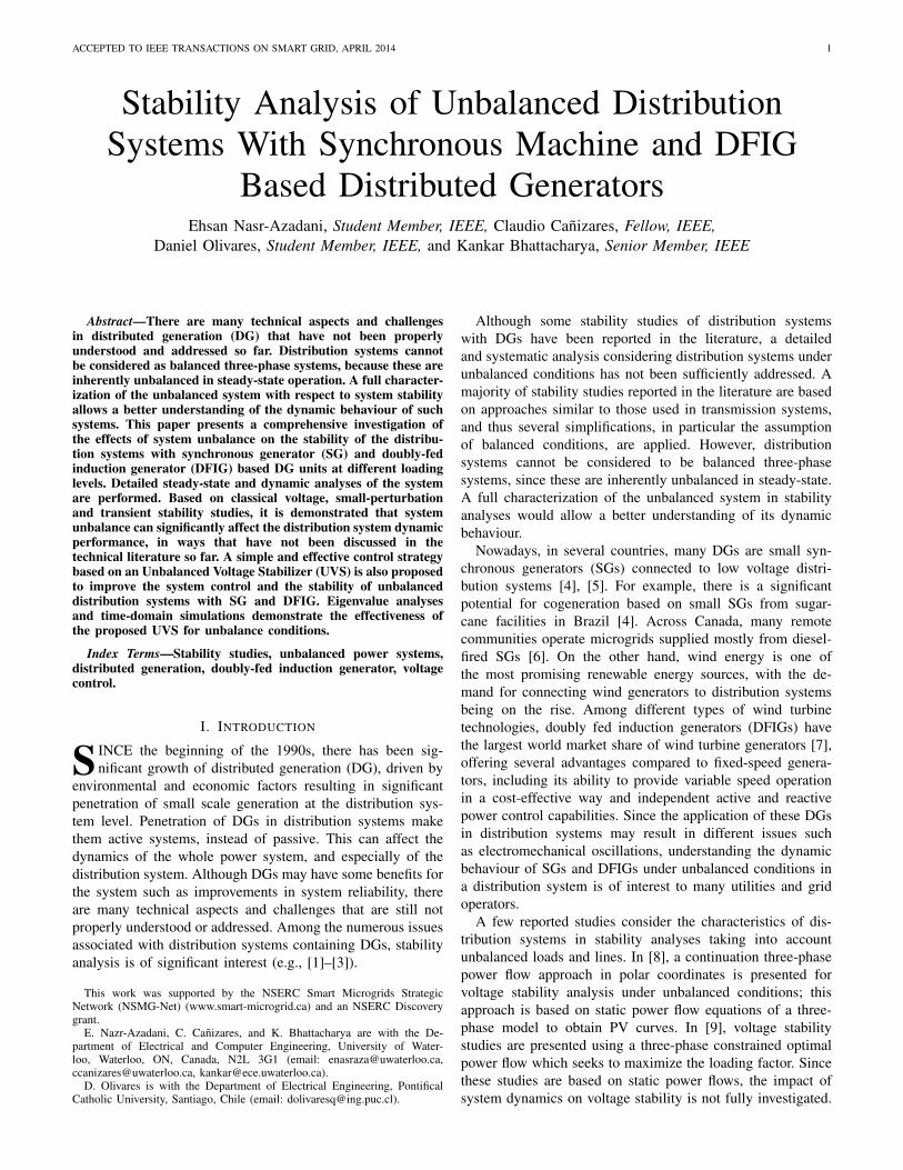
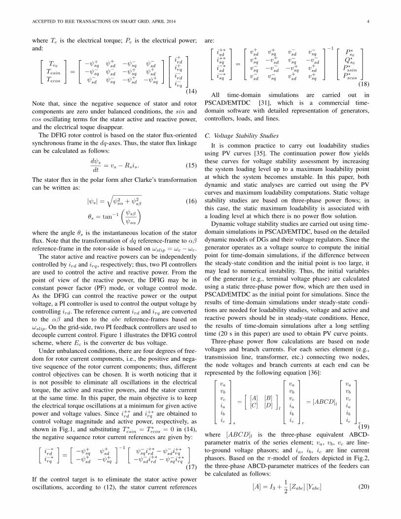
The stator active and reactive powers can be independentlycontrolled by ird and irq , respectively; thus, two PI controllersare used to control the active and reactive power. From thepoint of view of the reactive power, the DFIG may be inconstant power factor (PF) mode, or voltage control mode.As the DFIG can control the reactive power or the outputvoltage, a PI controller is used to control the output voltage bycontrolling ird. The reference current ird and irq are convertedto the αβ and then to the abc reference-frames based onωslip. On the grid-side, two PI feedback controllers are used todecouple current control. Figure 1 illustrates the DFIG controlscheme, where Ec is the converter dc bus voltage.
Under unbalanced conditions, there are four degrees of free-dom for rotor current components, i.e., the positive and nega-tive sequence of the rotor current components; thus, differentcontrol objectives can be chosen. It is worth noticing that itis not possible to eliminate all oscillations in the electricaltorque, the active and reactive powers, and the stator currentat the same time. In this paper, the main objective is to keepthe electrical torque oscillations at a minimum for given activepower and voltage values. Since i+∗
rd and i+∗rq are obtained to
control voltage magnitude and active power, respectively, asshown in Fig.1, and substituting T ∗
esin = T ∗ecos = 0 in (14),
the negative sequence rotor current references are given by:[i−∗rd
i−∗rq
]=
[−ψ+
sq ψ+sd
−ψ+sd −ψ+
sq
]−1 [ψ−sqi
+∗rd − ψ
−sdi
+∗rq
−ψ−sdi
+∗rd − ψ−
sqi+∗rq
](17)
If the control target is to eliminate the stator active poweroscillations, according to (12), the stator current references
All time-domain simulations are carried out inPSCAD/EMTDC [31], which is a commercial time-domain software with detailed representation of generators,controllers, loads, and lines.
C. Voltage Stability Studies
It is common practice to carry out loadability studiesusing PV curves [35]. The continuation power flow yieldsthese curves for voltage stability assessment by increasingthe system loading level up to a maximum loadability pointat which the system becomes unstable. In this paper, bothdynamic and static analyses are carried out using the PVcurves and maximum loadability computations. Static voltagestability studies are based on three-phase power flows; inthis case, the static maximum loadability is associated witha loading level at which there is no power flow solution.
Dynamic voltage stability studies are carried out using time-domain simulations in PSCAD/EMTDC, based on the detaileddynamic models of DGs and their voltage regulators. Since thegenerator operates as a voltage source to compute the initialpoint for time-domain simulations, if the difference betweenthe steady-state condition and the initial point is too large, itmay lead to numerical instability. Thus, the initial variablesof the generator (e.g., terminal voltage phase) are calculatedusing a static three-phase power flow, which are then used inPSCAD/EMTDC as the initial point for simulations. Since theresults of time-domain simulations under steady-state condi-tions are needed for loadability studies, voltage and active andreactive powers should be in steady-state conditions. Hence,the results of time-domain simulations after a long settlingtime (20 s in this paper) are used to obtain PV curve points.
Three-phase power flow calculations are based on nodevoltages and branch currents. For each series element (e.g.,transmission line, transformer, etc.) connecting two nodes,the node voltages and branch currents at each end can berepresented by the following equation [36]:
vavbvciaibic
s
=
[[A] [B][C] [D]
]l
vavbvciaibic
r
= [ABCD]l
vavbvciaibic
r(19)
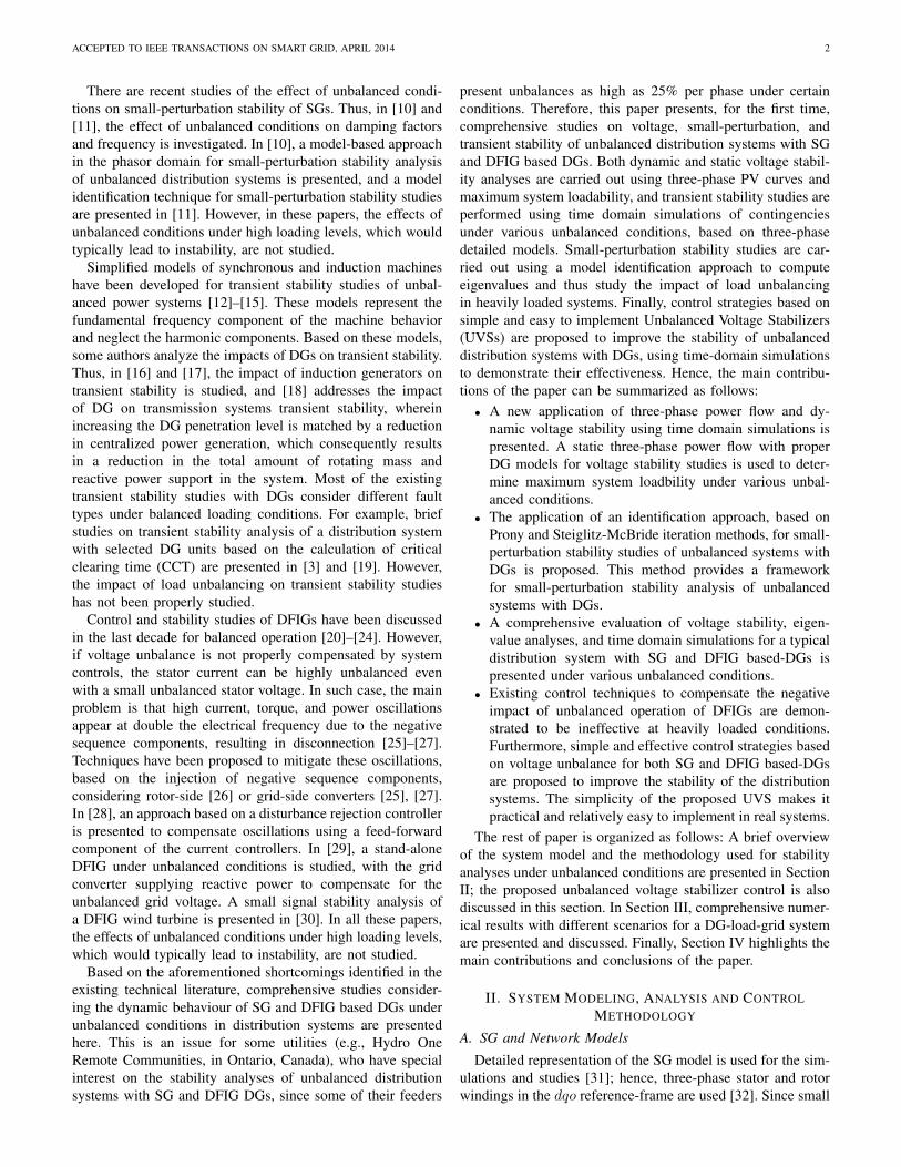
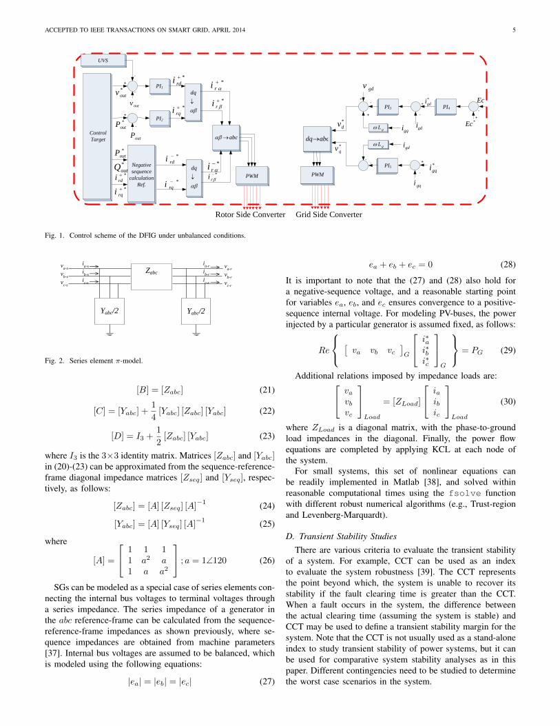
where [ABCD]l is the three-phase equivalent ABCD-parameter matrix of the series element; va, vb, vc are line-to-ground voltage phasors; and ia, ib, ic are line currentphasors. Based on the π-model of feeders depicted in Fig.2,the three-phase ABCD-parameter matrices of the feeders canbe calculated as follows:
[A] = I3 +1
2[Zabc] [Yabc] (20)
ACCEPTED TO IEEE TRANSACTIONS ON SMART GRID, APRIL 2014 5
PI4PI3
PI5
*
gdi
gdi
gdi
*
gqi
gqi
gqigL
gL
gdvPI1
PI2
UVS
*
ri
*
ri
*
ri*
ri
abc abcdq
dq
dqPWMPWM
Negative
sequence
calculation
Ref.
*
rdi
*
rqi
*
qv
*
dv
*
outv
*
outP
outP
outv
*
rdi
*
rqi
*
rdi
*
rqi
*
outP
*
outQ
Control
Target
+
-
+
-
-
+
+
+
-
-+
-
-
*Ec
Ec
+
-
Rotor Side Converter Grid Side Converter
-
Fig. 1. Control scheme of the DFIG under unbalanced conditions.
Zabc
Yabc/2
Yabc/2
va-r
vb-r
vc-r
va-s
vb-s
vc-s
ia-s
ib-s
ic-s
ia-r
ib-r
ic-r
Fig. 2. Series element π-model.
[B] = [Zabc] (21)
[C] = [Yabc] +1
4[Yabc] [Zabc] [Yabc] (22)
[D] = I3 +1
2[Zabc] [Yabc] (23)
where I3 is the 3×3 identity matrix. Matrices [Zabc] and [Yabc]in (20)-(23) can be approximated from the sequence-reference-frame diagonal impedance matrices [Zseq] and [Yseq], respec-tively, as follows:
[Zabc] = [A] [Zseq] [A]−1 (24)
[Yabc] = [A] [Yseq] [A]−1 (25)
where
[A] =
1 1 11 a2 a1 a a2
; a = 1∠120 (26)
SGs can be modeled as a special case of series elements con-necting the internal bus voltages to terminal voltages througha series impedance. The series impedance of a generator inthe abc reference-frame can be calculated from the sequence-reference-frame impedances as shown previously, where se-quence impedances are obtained from machine parameters[37]. Internal bus voltages are assumed to be balanced, whichis modeled using the following equations:
|ea| = |eb| = |ec| (27)
ea + eb + ec = 0 (28)
It is important to note that the (27) and (28) also hold fora negative-sequence voltage, and a reasonable starting pointfor variables ea, eb, and ec ensures convergence to a positive-sequence internal voltage. For modeling PV-buses, the powerinjected by a particular generator is assumed fixed, as follows:
Re
[va vb vc
]G
i∗ai∗bi∗c
G
= PG (29)
Additional relations imposed by impedance loads are: vavbvc
Load
= [ZLoad]
iaibic
Load
(30)
where ZLoad is a diagonal matrix, with the phase-to-groundload impedances in the diagonal. Finally, the power flowequations are completed by applying KCL at each node ofthe system.
For small systems, this set of nonlinear equations canbe readily implemented in Matlab [38], and solved withinreasonable computational times using the fsolve functionwith different robust numerical algorithms (e.g., Trust-regionand Levenberg-Marquardt).
D. Transient Stability StudiesThere are various criteria to evaluate the transient stability
of a system. For example, CCT can be used as an indexto evaluate the system robustness [39]. The CCT representsthe point beyond which, the system is unable to recover itsstability if the fault clearing time is greater than the CCT.When a fault occurs in the system, the difference betweenthe actual clearing time (assuming the system is stable) andCCT may be used to define a transient stability margin for thesystem. Note that the CCT is not usually used as a stand-aloneindex to study transient stability of power systems, but it canbe used for comparative system stability analyses as in thispaper. Different contingencies need to be studied to determinethe worst case scenarios in the system.
ACCEPTED TO IEEE TRANSACTIONS ON SMART GRID, APRIL 2014 6
E. Small-Perturbation Stability Studies
Eigenvalue analysis of the system state matrix is one ofthe common tools for small-perturbation stability studies. Inthe context of power systems, several simplifications such assystem modeling under balanced conditions are applied. Thus,the system is usually modeled with single-phase equivalents,so that small-perturbation stability analysis of a balancedpower system can be normally carried out by the linearizationof the power system model around an equilibrium point.Many commercial programs use phasor models for small-perturbation stability studies, and assume a specific equi-librium point under steady-state conditions. In the case ofunbalanced condition, equilibrium points are non-stationarywith respect to the angular velocity of the SGs, since thegenerator velocity is sinusoidal under steady-state conditions;hence, standard phasor-based linearization techniques are notapplicable in this case [10].
There are two approaches for small-perturbation stabilitystudies under unbalanced conditions: a model based approach,and a modal estimation approach [10], [40]. In this pa-per, small-perturbation stability analyses are performed usingmodal estimations, in particular, the Prony method and theSteiglitz-McBride iteration method [41], [42], based on time-domain simulations.
As mentioned in the previous section, PSCAD/EMTDCprovides data to analyze the dynamics of the system, which isthen used here in an appropriate modal estimation method,i.e., Steiglitz-McBride iteration and Prony, to estimate thesystem eigenvalues. In the studies presented in this paper,the generator speed from time-domain simulations is used asa signal for the modal estimation method. The conventionalProny method available in Matlab is used in this paper [38].
The Prony method is suitable for transient stability studieswith high signal to noise ratio (SNR). However, when thesystem becomes unstable, the Prony method cannot follow thesignal properly. In this case, the Steiglitz-McBride iterationmethod has better performance. Figure 3 presents a compar-ison of the measured data and the estimated signal by Pronyand Steiglitz-McBride iteration methods when the system isunstable. Note that the Steiglitz-McBride iteration method fitsthe signal well, while the Prony method is unable to extractthe true poles of the signal when the system is unstable.
Since the length of the output data of the time-domainsimulation is too long (e.g., 20000 points in a 10 s simulation),it is assumed that the signal is divided in sets of 0.5 s windowdata, with each set of data being then used in the identificationmethods to estimate the signal, giving a number of poles andzeros. Based on the nature of the signal and using mean-square-errors, the number of poles was set to 8 here.
F. Proposed Unbalanced Voltage Stabilizer
When a system is more heavily loaded, it can becomeunstable as unbalancing increases and the critical poles crossthe imaginary axes, as discussed in Section III. Since thisresults in oscillatory modes, a UVS is proposed to mitigatethese oscillations, integrating it with the generator voltageregulator to provide an auxiliary stabilizing signal.
Fig. 3. Measured data and estimated signal when the system is unstable forthe test system discussed in Section III.
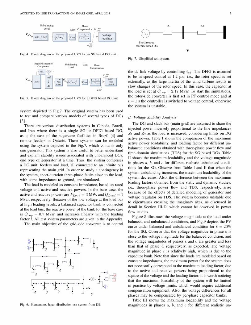
Figure 4 shows the proposed UVS for the SG based DG.This UVS provides a damping torque component when thesystem is unbalanced; hence, the input signals used here arethe voltage magnitudes in all phases. These are then convertedto the dqo reference-frame based on: vd
For θ = 0, the transformation√v2d + v2q can be used to reflect
the degree of unbalance, since as the unbalance increases, theoutput signal increases as well. The gain KUV S determinesthe damping factor provided by the UVS, and the first-orderphase compensation block provides appropriate phase lead tocompensate for the phase lag between the voltage regulatorinput and the generator electrical torque. The limits V maxUV S
and V minUV S constrain the output signal, which is an auxiliarynegative-feedback signal for the voltage regulator, due to thefact that by decreasing the generator terminal voltages, the loaddemand decreases, thus reducing the system stress as demandand unbalance increase. Therefore, stability can be improvedas the load increases with the proposed UVS.
The tuning of the UVS parameters would be similar to thatof the power system stabilizer in power systems; thus, the gainKUV S should be set to guarantee system stability, since if thisgain is tuned improperly, the system may be unstable, and thetime constants should be selected to compensate for the phaselags of the system. The UVS parameter values used here areprovided in the Appendix.
Figure 5 shows the proposed UVS for the DFIG, basedon similar principles as the SG UVS. Since the negative-sequence components of terminal voltages are available forDFIG control, these signals are used here and then convertedto the dq− reference-frame.
III. RESULTS
A. Test System
The distribution system in the Kumamoto area in Japan from[43] shown in Fig.6, is used to develop the simplified test
ACCEPTED TO IEEE TRANSACTIONS ON SMART GRID, APRIL 2014 7
22
qd vv sT
sT
U
U
2
1
1
1
UVSK
Max
UVSV
Min
UVSV
Unbalancing
Level Gain
Phase
Compensation
abcvdqoabc
Voltage
regulator
Fig. 4. Block diagram of the proposed UVS for an SG based DG unit.
Clarke
Low
Pass
Filter
abcv
dq
PLL
22 qd vv
dqvsT
sT
U
U
2
1
1
1
UVSK
Max
UVSV
Min
UVSV
-1
Unbalancing
LevelGain Phase
Compensation
Negative Sequence
Components
DFIG
rotor
control
Fig. 5. Block diagram of the proposed UVS for a DFIG based DG unit.
system depicted in Fig.7. The original system has been usedto test and compare various models of several types of DGs[3].
There are various distribution systems in Canada, Brazil,and Iran where there is a single SG or DFIG based DG,as is the case of the sugarcane facilities in Brazil [4] andremote feeders in Ontario. These systems can be modeledusing the system depicted in the Fig.7, which contains onlyone generator. This system is also useful to better understandand explain stability issues associated with unbalanced DGs,one type of generator at a time. Thus, the system comprisesa DG unit, feeders and load, all connected to an infinite busrepresenting the main grid. In order to study a contingency inthe system, short-duration three-phase faults close to the load,with some impedance to ground, are simulated.
The load is modeled as constant impedance, based on ratedvoltage and active and reactive powers. In the base case, theactive and reactive powers are PLoad = 3 MW, and QLoad = 1Mvar, respectively. Because of the low voltage at the load busat high loading levels, a balanced capacitor bank is connectedat the load bus; the reactive power of the bank for the base caseis Qcap = 0.7 Mvar, and increases linearly with the loadingfactor l. All test system parameters are given in the Appendix.
The main objective of the grid-side converter is to control
Bus9Bus8Bus7
Bus6
Bus5
Bus4
Bus3Bus2
Bus16
Bus15
Bus14
Bus13
Bus12
Bus11
Bus10
Bus1
Fig. 6. Kumamoto, Japan distribution test system from [3].
Z1 Z2
Synchronous
machine based DG
Fig. 7. Simplified test system.
the dc link voltage by controlling igd. The DFIG is assumedto be in speed control at 1.2 p.u, i.e., the rotor speed is setexternally, as the large inertia of the wind turbine results inslow changes of the rotor speed. In this case, the capacitor atthe load is set at Qcap = 2.17 Mvar. To start the simulations,the rotor-side converter is first set in PF control mode and att = 1 s the controller is switched to voltage control, otherwisethe system is unstable.
B. Voltage Stability Analysis
The DG and slack bus (main grid) are assumed to share theinjected power inversely proportional to the line impedancesZ1 and Z2 as the load is increased, considering limits on DGactive power. Table I shows the comparison of the maximumactive power loadability, and loading factor for different un-balanced conditions obtained with three-phase power flow andtime-domain simulations (TDS) for the SG based DGs. TableII shows the maximum loadability and the voltage magnitudein phases a, b, and c for different realistic unbalanced condi-tions for the SG. Observe from Table I and II that when thesystem unbalancing increases, the maximum loadability of thesystem decreases. Also, the difference between the maximumloading factors obtained from the static and dynamic studies,i.e., three-phase power flow and TDS, respectively, arisebecause of the effects of detailed modeling of generator andvoltage regulator on TDS. The system becomes unstable dueto eigenvalues crossing the imaginary axes, as discussed indetail in Section III-D, which cannot be observed in powerflow studies.
Figure 8 illustrates the voltage magnitude at the load underbalanced and unbalanced conditions, and Fig.9 depicts the PVcurve under balanced and unbalanced condition for k = 20%for the SG. Observe that the voltage magnitude in phase b isclose to the voltage magnitude for the balanced condition, andthe voltage magnitudes of phases c and a are greater and lessthan that of phase b, respectively, as expected. The voltagemagnitude in phase c is relatively high, which is due to thecapacitor bank. Note that since the loads are modeled based onconstant impedances, the maximum power for the system doesnot necessarily correspond to the maximum loading factor, dueto the active and reactive powers being proportional to thesquare of the voltage and the loading factor. It is worth noticingthat the maximum loadability of the system will be limitedin practice by voltage limits, which would require additionalcompensation equipment. Also, the voltage differences for allphases may be compensated by per-phase capacitor banks.
Table III shows the maximum loadability and the voltagemagnitudes in phases a, b, and c for different realistic un-
ACCEPTED TO IEEE TRANSACTIONS ON SMART GRID, APRIL 2014 8
TABLE IMAXIMUM ACTIVE POWERS AND LOADING FACTORS FOR DIFFERENT
UNBALANCED CONDITIONS FOR STATIC THREE-PHASE POWER FLOW ANDTIME-DOMAIN SIMULATIONS WITH SG.
k(%) Maximum loading factor (p.u.)Maximum active power
loadability (p.u.)
TDS Three-phase PF TDS Three-phase PF
0 2.2 2.24 0.692 0.6925
5 2.2 2.24 0.692 0.6925
10 2.2 2.22 0.691 0.6923
15 2.2 2.22 0.691 0.6917
20 2.15 2.20 0.689 0.6912
25 2.1 2.18 0.687 0.6903
TABLE IIMAXIMUM ACTIVE POWER AND VOLTAGE MAGNITUDE IN ALL PHASES
balanced conditions of the distribution system with DFIG.Observe that when the system unbalancing increases, themaximum loadability of the system decreases, and the voltagemagnitude differences in phases a, b, and c with respect to thevoltage magnitudes in balanced conditions increase.
Figure 10 shows the voltage magnitude at the load underbalanced and unbalanced conditions for k = 15% withDFIG, and Fig.11 depicts the PV curve under balanced andunbalanced condition. Observe that the voltage magnitude inphase b is close to the voltage magnitude for the balancedcondition, and the voltage magnitudes of phases c and a aregreater and less than that of phase b, respectively, as expected.
C. Transient Stability Analysis
Three-phase-to-ground faults of short-duration and close tothe load are considered as contingencies for the SG. Thesimulation time is 20 s, and the fault occurs at t = 3 s. TableIV illustrates the CCT of the test system with the SG and theDFIG for different values of k for the base loading factor (i.e.,
1 1.2 1.4 1.6 1.8 2 2.20.9
0.95
1
1.05
1.1
1.15
1.2
1.25
Loading Factor
Vol
tage
Mag
nitu
de (
p.u.
)
V balancedVaVbVc
Fig. 8. Load voltage magnitude versus loading factor with SG for k = 20%.
0.35 0.4 0.45 0.5 0.55 0.6 0.65 0.70.9
0.95
1
1.05
1.1
1.15
1.2
1.25
Total active power loading (p.u.)
Vol
tage
Mag
nitu
de (
p.u.
)
V balancedVaVbVc
Fig. 9. PV curves with SG for k = 20%.
1 1.05 1.1 1.15 1.2 1.250.94
0.96
0.98
1
1.02
1.04
1.06
1.08
Loading Factor
Vol
tage
Mag
nitu
de (
p.u.
)
V balancedVaVbVc
Fig. 10. Load voltage magnitude versus loading factor with DFIG for k =15%.
l = 1 p.u.). Observe that the CCT decreases as the unbalanceincreases, decreasing by 30% for the SG and 95% for theDFIG as k increases from 0% to 25%. Since the power ratingof the SG and the DFIG are different, the corresponding CCTsare not comparable with each other. It should be noted that,as the load increased, it was observed that the CCT remainedunchanged, due to the fact that the DG is at its maximumpower output at base load.
Figures 12 and 13 depict the transient behavior of the SG at
0.32 0.33 0.34 0.35 0.36 0.37 0.38 0.390.94
0.96
0.98
1
1.02
1.04
1.06
1.08
Total Active Power Loading (p.u.)
Vol
tage
Mag
nitu
de (
p.u.
)
V balancedVaVbVc
Fig. 11. PV curves with DFIG for k = 15%.
TABLE IIIMAXIMUM ACTIVE POWER AND VOLTAGE MAGNITUDE IN ALL PHASES
ACCEPTED TO IEEE TRANSACTIONS ON SMART GRID, APRIL 2014 9
Fig. 12. Transient behavior of SG at k = 25% before CCT.
TABLE IVCCT OF THE TEST SYSTEM AT BASE LOAD (l = 1 P.U.) FOR A
THREE-PHASE-TO-GROUND FAULT.
k(%)CCT of the test system
with the SG (s)CCT of the test system
with DFIG (s)0 0.45 0.15 0.42 0.1
10 0.40 0.115 0.37 0.0520 0.35 0.00525 0.30 0.005
a loading factor l = 1.5 p.u. and k = 25% for the studied faultbefore and after the CCT. Observe that the system is stable fora clearing time 0.12 s, and unstable for clearing times greaterthan 0.12 s.
D. UVS Impact on SG
Two scenarios are considered to analyze the effects ofunbalanced conditions on small-perturbation stability for theSG, as follows:
1) Effect of Unbalancing at Base Load: In the first scenario,the load is at the base case (i.e, l = 1 p.u.), and the systemis perturbed with a short-duration three-phase fault at t = 1s, so that the critical system modes can be obtained usingthe identification approach. This is used to study the systemstability under various unbalanced conditions at low loadinglevels, demonstrating the impact of unbalancing on the stable
Fig. 13. Transient behavior of SG at k = 25% after CCT.
TABLE VDAMPING FACTORS AND FREQUENCY OF OSCILLATIONS FOR DIFFERENT
UNBALANCED CONDITIONS.
Pole Damping factor (%) Frequency (rad/s)
k= 0% -1.09 + j12.7 8.53 12.7
k=5% -1.11 + j12.6 8.82 12.6
k=10% -1.12 + j12.5 8.89 12.6
k=15% -1.13 + j12.4 9.03 12.5
k=20% -1.14 + j12.3 9.25 12.3
k=25% -1.16 + j12.0 9.65 12.1
system. Table V illustrates the damping factors and frequencyof the critical poles at the base load for different unbalancedconditions. Note that as k increases, the frequency decreases,while the damping factor increases; similar observations werereported in [10] and [40].
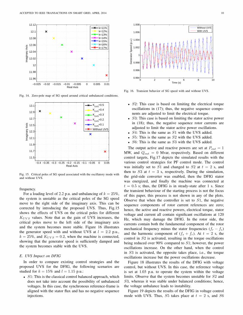
2) Effect of Unbalancing on High Loading Levels: In thesecond scenario, the system load is increased close to itsmaximum value (l = 2.2 p.u.), and the machine is thenconnected at t = 0.5 s. This is used to study the stability of thesystem for various unbalance conditions at high loading levels,demonstrating how unbalancing leads the system to instability.Figure 14 illustrates the critical poles of the SG speed forvarious levels of unbalanced conditions. Observe that, beyondk = 15%, the critical pole crosses the imaginary axis andthus the system experiences a Hopf bifurcation with 1.91 Hz
ACCEPTED TO IEEE TRANSACTIONS ON SMART GRID, APRIL 2014 10
−0.025 −0.02 −0.015 −0.01 −0.005 0 0.005 0.01
11.96
11.98
12
12.02
12.04
12.06
12.08
12.1
12.12
Real Axis
Imag
inar
y A
xis
k=11%k=12%k=13%k=14%k=15%k=16%k=17%
Fig. 14. Zero-pole map of SG speed around critical unbalanced conditions.
Fig. 15. Critical poles of SG speed associated with the oscillatory mode withand without UVS.
frequency.For a loading level of 2.2 p.u. and unbalancing of k = 25%,
the system is unstable as the critical poles of the SG speedmove to the right side of the imaginary axis. This can becorrected by introducing the proposed UVS. Thus, Fig.15shows the effects of UVS on the critical poles for differentKUV S values. Note that as the gain of UVS increases, thecritical poles move to the left side of the imaginary axisand the system becomes more stable. Figure 16 illustratesthe generator speed with and without UVS at l = 2.2 p.u.,k = 25%, and KUV S = 0.2, when the machine is connected,showing that the generator speed is sufficiently damped andthe system becomes stable with the UVS.
E. UVS Impact on DFIG
In order to compare existing control strategies and theproposed UVS for the DFIG, the following scenarios arestudied for k = 15% and l = 1.15 p.u.:
• S1: This is the classical control balanced approach, whichdoes not take into account the possibility of unbalancedvoltages. In this case, the synchronous reference-frame isaligned with the stator flux and has no negative sequenceinjections.
0 2 4 6 8 100.994
0.996
0.998
1
1.002
1.004
1.006
1.008
Time (s)
Gen
erat
or S
peed
(p.
u.)
Without UVSWith UVS
Fig. 16. Transient behavior of SG speed with and without UVS.
• S2: This case is based on limiting the electrical torqueoscillations in (17); thus, the negative sequence compo-nents are adjusted to limit the electrical torque.
• S3: This case is based on limiting the stator active powerin (18); thus, the negative sequence rotor currents areadjusted to limit the stator active power oscillations.
• S4: This is the same as S1 with the UVS added.• S5: This is the same as S2 with the UVS added.• S6: This is the same as S3 with the UVS added.The output active and reactive powers are set at Pout = 1
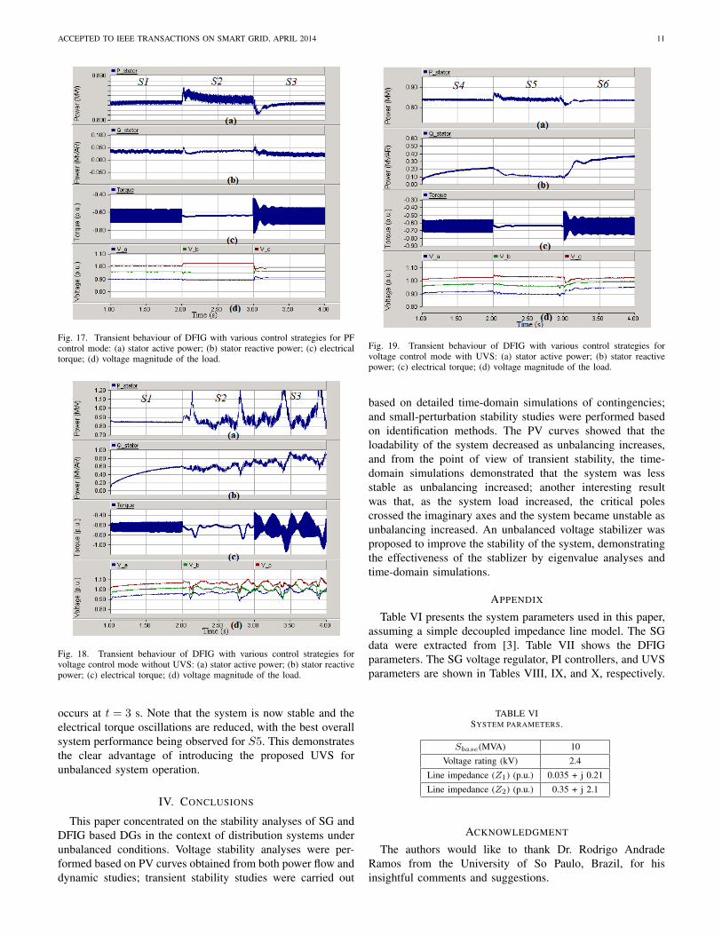
MW, and Qout = 0 Mvar, respectively. Based on differentcontrol targets, Fig.17 depicts the simulated results with thevarious control strategies for PF control mode. The controlwas initially set to S1 and changed to S2 at t = 2 s, andthen to S3 at t = 3 s, respectively. During the simulation,the grid-side converter was enabled, then the DFIG statorwas energized, and finally the machine was connected att = 0.5 s; thus, the DFIG is in steady-state after 1 s. Sincethe transient behaviour of the starting process is not the focusof this paper, this process is not shown in any of the plots.Observe that when the controller is set to S1, the negativesequence components of rotor current references are zero;hence, the active and reactive powers, electrical torque, statorvoltage and current all contain significant oscillations at 120Hz, which may damage the DFIG. In the rotor side, thecurrents contain both the fundamental component of the rotormechanical frequency minus the stator frequencies (fr − fs)and the harmonic component of (fs + fr). At t = 2 s, thecontrol in S2 is activated, resulting in the torque oscillationsbeing reduced over 90% compared to S1; however, the poweroscillations increase. On the other hand, when the controlin S3 is activated, the opposite takes place, i.e., the torqueoscillations increase but the power oscillations decrease.
Figure 18 illustrates the results of the DFIG with voltagecontrol, but without UVS. In this case, the reference voltageis set at 1.03 p.u. to operate the system within the voltagelimits. Observe that the system becomes unstable for S2 andS3, whereas it was stable under balanced conditions; hence,the voltage unbalance leads to instability.
Figure 19 depicts the results of the DFIG in voltage controlmode with UVS. Thus, S5 takes place at t = 2 s, and S6
ACCEPTED TO IEEE TRANSACTIONS ON SMART GRID, APRIL 2014 11
Fig. 17. Transient behaviour of DFIG with various control strategies for PFcontrol mode: (a) stator active power; (b) stator reactive power; (c) electricaltorque; (d) voltage magnitude of the load.
Fig. 18. Transient behaviour of DFIG with various control strategies forvoltage control mode without UVS: (a) stator active power; (b) stator reactivepower; (c) electrical torque; (d) voltage magnitude of the load.
occurs at t = 3 s. Note that the system is now stable and theelectrical torque oscillations are reduced, with the best overallsystem performance being observed for S5. This demonstratesthe clear advantage of introducing the proposed UVS forunbalanced system operation.
IV. CONCLUSIONS
This paper concentrated on the stability analyses of SG andDFIG based DGs in the context of distribution systems underunbalanced conditions. Voltage stability analyses were per-formed based on PV curves obtained from both power flow anddynamic studies; transient stability studies were carried out
Fig. 19. Transient behaviour of DFIG with various control strategies forvoltage control mode with UVS: (a) stator active power; (b) stator reactivepower; (c) electrical torque; (d) voltage magnitude of the load.
based on detailed time-domain simulations of contingencies;and small-perturbation stability studies were performed basedon identification methods. The PV curves showed that theloadability of the system decreased as unbalancing increases,and from the point of view of transient stability, the time-domain simulations demonstrated that the system was lessstable as unbalancing increased; another interesting resultwas that, as the system load increased, the critical polescrossed the imaginary axes and the system became unstable asunbalancing increased. An unbalanced voltage stabilizer wasproposed to improve the stability of the system, demonstratingthe effectiveness of the stablizer by eigenvalue analyses andtime-domain simulations.
APPENDIX
Table VI presents the system parameters used in this paper,assuming a simple decoupled impedance line model. The SGdata were extracted from [3]. Table VII shows the DFIGparameters. The SG voltage regulator, PI controllers, and UVSparameters are shown in Tables VIII, IX, and X, respectively.
TABLE VISYSTEM PARAMETERS.
Sbase(MVA) 10
Voltage rating (kV) 2.4
Line impedance (Z1) (p.u.) 0.035 + j 0.21
Line impedance (Z2) (p.u.) 0.35 + j 2.1
ACKNOWLEDGMENT
The authors would like to thank Dr. Rodrigo AndradeRamos from the University of So Paulo, Brazil, for hisinsightful comments and suggestions.
ACCEPTED TO IEEE TRANSACTIONS ON SMART GRID, APRIL 2014 12
TABLE VIIDFIG PARAMETERS.
Power rating (MVA) 1.717
Voltage rating (kV) 0.69
Stator/rotor turn ratio 0.335
Rs (p.u.) 0.005049
Rr (p.u.) 0.00357
Ls (p.u.) 0.1226
Lr (p.u.) 0.1118
Lm (p.u.) 2.0773
2H (sec) 4.55
TABLE VIIISG VOLTAGE REGULATOR PARAMETERS.
Maximum regulator voltage (p.u.) 6
Minimum regulator voltage (p.u.) 0
Regulator gain 78
Regulator pole (sec) 10
Regulator zero (sec) 1
Time constant of the field circuit Td (sec) 1
TABLE IXPI CONTROLLERS PARAMETERS.
PI1 PI2 PI3 PI4 PI5
Proportional gain 1 0.5 5 10 10
Integral time constant (sec) 0.1 0.2 0.05 0.01 0.01
TABLE XUVS PARAMETERS.
SG DFIG
KUV S 0.2 1.1
TU1 (sec) 0.125 0.125
TU2 (sec) 0.030 0.030
VmaxUV S (p.u.) 0.2 0.2
VminUV S (p.u.) -0.2 -0.2
REFERENCES
[1] M. Reza, J. G.Slootweg, P. H. Schavemaker, W. L. Kling, and L. V. derSluis, “Investigating impacts of distributed generation on transmissionsystem stability,” in Proc. IEEE Power Tech Conference, Bologna, Jun.2003.
[2] A. M. Azmy and I. Erlich, “Impact of distributed generation on thestability of electrical power system,” in Proc. IEEE PES GeneralMeeting, Jun. 2005.
[3] E. Nasr-Azadani, C. Canizares, and K. Bhattacharya, “Modeling andstability analysis of distributed generation,” in Proc. IEEE PES GeneralMeeting, Jul. 2012.
[4] S. Granville, P. Lino, F. Ralston, L. A. Barroso, and M. Pereira, “Recentadvances of sugarcane biomass cogeneration in brazil,” in Proc. IEEEPES General Meeting, Jul. 2009.
[5] M. Wang and J. Zhong, “Development of distributed generation inchina,” in Proc. IEEE PES General Meeting, Jul. 2009.
[6] M. Arriaga, C. A. Caizares, and M. Kazerani, “Renewable energyalternatives for remote communities in northern ontario, canada,” IEEETrans. Sustainable Energy, vol. 4, no. 3, pp. 661–670, 2013.
[7] T. Ackermann, Wind Power in Power Systems. NJ: Wiley: Hoboken,2005.
[8] X.-P. Zhang, P. Ju, and E. Handschin, “Voltage stability analysis inunbalanced power systems by optimal power flow,” IEEE Trans. PowerSyst., vol. 20, no. 3, pp. 1320–1329, Aug. 2005.
[9] D. Lauria and P. Varilone, “Continuation three-phase power flow: A toolfor voltage stability analysis of unbalanced three-phase power systems,”Proc. IET Gen., Trans. and Dist., vol. 153, no. 3, pp. 261–268, May2006.
[10] R. H. Salim and R. A. Ramos, “A model-based approach for small-signal stability assessment of unbalanced power systems,” IEEE Trans.Power Syst., vol. 27, no. 4, pp. 1184–1190, Nov. 2012.
[11] ——, “A framework for analyzing the small-signal dynamic performanceof unbalanced power systems,” in Proc. IEEE PES General Meeting, Jul.2011.
[12] R. G. Harley, E. B. Makram, and E. G. Duran, “The effects ofunbalanced networks and unbalanced faults on induction motor transientstability,” IEEE Trans. Energy Convers., vol. 3, no. 2, pp. 398–403, 1988.
[13] E. B. Makram, V. O. Zambrano, R. G. Harley, and J. C. Balda,“Three-phase modeling for transient stability of large scale unbalanceddistribution systems,” IEEE Trans. Power Syst., vol. 4, no. 2, pp. 487–493, 1989.
[14] R. G. Harley, E. B. Makram, and E. G. Duran, “The effects of un-balanced networks on synchronous and asynchronous machine transientstability,” Elect. Power Syst. Res., vol. 13, no. 2, pp. 119–127, 1987.
[15] E. B. Makram, V. O. Zambrano, and R. G. Harley, “Synchronousgenerator stability due to multiple faults on unbalanced power systems,”Elect. Power Syst. Res., vol. 15, no. 1, pp. 31–39, 1988.
[16] V. Akhmatov, “Analysis of dynamic behaviour of electric power sys-tems with large amount of wind power,” Ph.D. dissertation, Technicaluniversity of Denmark, Lyngby, Denmark, 2003.
[17] A. P. Grilo, A. d. A. Mota, L. T. M. Mota, and W. Freitas, “Ananalytical method for analysis of large-disturbance stability of inductiongenerators,” IEEE Trans. Power Syst., vol. 22, no. 4, pp. 1861–1869,2007.
[18] M. Reza, “Stability analysis of transmission systems with high penetra-tion of distributed generation,” Ph.D. dissertation, Delft University ofTechnology, Delft, Netherlands, 2006.
[19] I. Xyngi, A. Ishchenko, M. Popov, and L. van der Sluis, “Transientstability analysis of a distribution network with distributed generators,”IEEE Trans. Power Syst., vol. 24, no. 2, pp. 1102–1104, May 2009.
[20] P. Ledesma and J. Usaola, “DFIG model for transient stability analysis,”IEEE Trans. Energy Convers., vol. 20, no. 2, pp. 388–397, Jun. 2005.
[21] Y. Lei, A. Mullane, G. Lightbody, and R. Yacamini, “Modeling of thewind turbine with a DFIG for grid integration studies,” IEEE Trans.Energy Convers., vol. 21, no. 1, pp. 257–264, Mar. 2006.
[22] D. Xiang, L. Ran, P. Tavner, and S. Yang, “Control of a DFIG in a windturbine during grid fault ride through,” IEEE Trans. Energy Convers.,vol. 21, no. 3, pp. 652–662, Sep. 2006.
[23] J. Morren and S. de Haan, “Ride through of wind turbines with DFIGduring a voltage dip,” IEEE Trans. Energy Convers., vol. 20, no. 2, pp.435–441, Jun. 2008.
[24] ——, “Short-circuit current of wind turbines with DFIG,” IEEE Trans.Energy Convers., vol. 22, no. 1, pp. 174–180, Mar. 2007.
[25] O. Gomis-Bellmunt, A. Junyent-Ferre, A. Sumper, and J. Bergas-Jan,“Ride-through control of a DFIG under unbalanced voltage sags,” IEEETrans. Energy Convers., vol. 23, no. 4, pp. 1036–1045, Dec. 2008.
[26] L. Xu and Y. Wang, “Dynamic modeling and control of DFIG-basedwind turbines under unbalanced network conditions,” IEEE Trans. PowerSyst., vol. 22, no. 1, pp. 1320–1329, Feb. 2007.
[27] Y. Zhou, P. Bauer, J. Ferreira, and J. Pierik, “Operation of grid-connectedDFIG under unbalanced grid voltage condition,” IEEE Trans. EnergyConvers., vol. 24, no. 1, pp. 240–246, Mar. 2009.
[28] T. K. A. Brekken and N. Mohan, “Control of a doubly fed inductionwind generator under unbalanced grid voltage conditions,” IEEE Trans.Energy Convers., vol. 22, no. 1, pp. 129–135, Mar. 2007.
[29] R. Pena, R. Cardenas, E. Escobar, J. Clare, and P. Wheeler, “Controlsystem for unbalanced operation of stand-alone DFIGs,” IEEE Trans.Energy Convers., vol. 22, no. 2, p. 544545, Jun. 2007.
[30] L. Yang, Z. Xu, J. Ostergaard, Z. Y. Dong, K. Wong, and X. Ma,“Oscillatory stability and eigenvalue sensitivity analysis of a DFIG windturbine system,” IEEE Trans. Energy Convers., vol. 26, no. 1, pp. 328–339, Mar. 2011.
[32] P. Kundur, Power System Stability and Control. New York: McGraw-Hill, 1994.
[33] R. H. Salim and R. A. Ramos, “Analyzing the effect of the type ofterminal voltage feedback on the small signal dynamic performanceof synchronous generators,” in Proc. IREP Symp. Bulk Power SystemDynamics and Control, Aug. 2010.
ACCEPTED TO IEEE TRANSACTIONS ON SMART GRID, APRIL 2014 13
[34] N. Mohan, T. M. Undeland, and W. Robbins, Power electronics:converters, applications, and design. New York: Wiley, 2007.
[35] “Voltage stability assessment: Concepts, practices and tools,” IEEE/PESPower System Stability Subcommittee, Tech. Rep., Aug. 2002.
[36] W. H. Kersting, Distribution System Modeling and Analysis. CRCPress, 2006.
[37] M. Z. Kamh and R. Iravani, “Unbalanced model and power-flow analysisof microgrids and active distribution systems,” IEEE Trans. Power Del.,vol. 25, no. 4, pp. 2851–2858, Oct. 2010.
[38] MATLAB, The MathWorks Inc.[39] A. G. Exposito, A. J. Conejo, and C. Canizares, Electric Energy Systems,
Analysis and Operation. CRC Press, 2009.[40] R. H. Salim, R. A. Ramos, and N. G. Bretas, “Analysis of the small sig-
nal dynamic performance of synchronous generators under unbalancedoperating conditions,” in Proc. IEEE PES General Meeting, Jul. 2010.
[41] H. Ghasemi, “On-line monitoring and oscillatory stability margin predic-tion in power systems based on system identification,” Ph.D. dissertation,University of Waterloo, Waterloo, Canada, 2006.
[42] K. Steiglitz and L. E. McBride, “A technique for the identification oflinear systems,” IEEE Trans. Autom. Control, vol. AC-10, pp. 461–464,1965.
[43] S. Li, K. Tomsovic, and T. Hiyama, “Load following functions usingdistributed energy resources,” in Proc. IEEE PES Summer MeetingMeeting, Jul. 2000.
Ehsan Nasr-Azadani (S’11) received his M.Sc. degree in Electrical Engineer-ing from the Amirkabir University, Tehran, Iran, in 2009, and is currentlypursuing the Ph.D. degree in Electrical Engineering at the University ofWaterloo, Waterloo, ON, Canada. His research interests are in modeling,control, and stability issues in microgrids.
Claudio A. Canizares (S’86, M’91, SM’00, F’07) received the electricalengineer diploma from the Escuela Politecnica Nacional (EPN), Quito,Ecuador, in 1984 and the M.S. and Ph.D. degrees electrical engineering arefrom the University of Wisconsin-Madison in 1988 and 1991, respectively. Hehas held various academic and administrative positions at the Electrical andComputer Engineering Department of the University of Waterloo, Waterloo,ON, Canada, since 1993, where he is currently a full Professor, the HydroOne Endowed Chair, and an Associate Director of the Waterloo Institute forSustainable Energy (WISE). His research activities concentrate in the studyof stability, optimization, modeling, simulation, control, and computationalissues in power systems within the context of competitive electricity marketsand smart grids.
Dr. Canizares has been the recipient of various IEEE-PES Working Groupawards and holds and has held several leadership appointments in IEEE-PES technical committees and subcommittees. He is a registered ProfessionalEngineer in the province of Ontario and a Fellow of the Royal Society ofCanada and of the Canadian Academy of Engineering.
Daniel E. Olivares (S’11) was born in Santiago, Chile, and received the B.Sc.and the Engineer degree in electrical engineering from the University of Chilein Santiago in 2006 and 2008, respectively. He finished his Ph.D. studies inElectrical and Computer Engineering at the University of Waterloo, Waterloo,ON, Canada, in January 2014. His research interests include modeling,simulation, control and optimization of power systems in the context of smartgrids.
Kankar Bhattacharya (M’95, SM’01) received the Ph.D. degree in electricalengineering from the Indian Institute of Technology, New Delhi, India, in1993. He was in the faculty of Indira Gandhi Institute of DevelopmentResearch, Mumbai, India, during 1993-1998, and then the Department ofElectric Power Engineering, Chalmers University of Technology, Gothenburg,Sweden, during 1998-2002. He joined the E&CE Department of the Universityof Waterloo, Waterloo, ON, Canada, in 2003 where he is currently a full Pro-fessor. His research interests are in power system economics and operationalaspects