15
ISS Lancaster University: ISS Access Control Specifications v1c V1c Faris Ali

ISS
Lancaster University: ISS
Access Control Specifications v1c V1c
Faris Ali

Access Control Specifications v1c
1 | P a g e
Revision History Date Version Author Comments
27/09/13 V1b Phil Chandler
Added Appendix C – Summary of Required Information
27/11/13 V1c Phil Chandler
i) Removed Director level from circulation list ii) Addition of recommendation to fit magnetic locks to the secure side of controlled doors.
Distribution Schedule Name Title
Mark Jameson Head of Technical Infrastructure ISS
Craig MacDonald Head of Networking
Paul Boyd Senior Network Specialist
Faris Ali Network Specialist
Tabitha Tipper Systems Specialist
Philip Chandler Systems Specialist
Mike Sheppard Head of Facilities Infrastructure
Suzanne Parkinson Head of Project Delivery
Stuart Foy Senior Project Manager
Helen Wood Senior Project Manager
John Lee Assistant Project Manager
Chris Maughan Assistant Project Manager
Simon Corless Electrical Engineer
Andrew Newsham Electrical Supervisor
Ian Watson Fabric Supervisor
Access Control Specifications v1c
2 | P a g e
Table of Contents Revision History ...................................................................................................................................... 1
Distribution Schedule .............................................................................................................................. 1
Introduction ............................................................................................................................................ 3
System Components ............................................................................................................................... 3
Intelligent Door Controller Ethernet (lDCe) ............................................................................................ 4
Reader Groups, Access Groups and Time Zones..................................................................................... 4
Security and Implementation Considerations ........................................................................................ 5
Area Perimeter Fire Doors .................................................................................................................. 5
Mechanical and Electrical ................................................................................................................... 5
Cable Containment ............................................................................................................................. 6
Reader, Break Glass and Exit Hardware Installation ........................................................................... 6
Hardware Provision ................................................................................................................................. 7
Door Contacts and Sounders .............................................................................................................. 7
Break glass units .................................................................................................................................. 7
Exit switches ........................................................................................................................................ 7
Fire alarm interfacing .......................................................................................................................... 7
Reader specification ................................................................................................................................ 8
MiFare Classic ..................................................................................................................................... 8
Lock specification ................................................................................................................................ 8
Automatic Door Systems .................................................................................................................... 8
Lift control ........................................................................................................................................... 8
System commissioning & Handover ....................................................................................................... 9
References ............................................................................................................................................ 10
Appendix A ............................................................................................................................................ 11
Hellerman Sleeving ........................................................................................................................... 11
IDCe Wiring Diagram ......................................................................................................................... 12
Appendix B - Lock Interface Parameters ............................................................................................... 13
Appendix C – Summary of Required Information ................................................................................. 14
Access Control Specifications v1c
3 | P a g e
Introduction
This document is to assist in the design and specification wherever there is a requirement to install the ISS managed Janus Access Control Solution. There may be some instances where changes to this specification are allowed or recommended by ISS, therefore it is recommended that contact is made to discuss requirements early in the planning stages of a project. The contacts for ISS are as follows: Faris Ali 01524 510146 [email protected] Paul Boyd 01524 510103 [email protected] Phil Chandler 01524 510106 [email protected] Paul Tipper 01524 510158 [email protected] The correct provision of an access control solution need not be onerous if the correct requirements are identified and provided for. Each circumstance requires an individual and methodical approach.
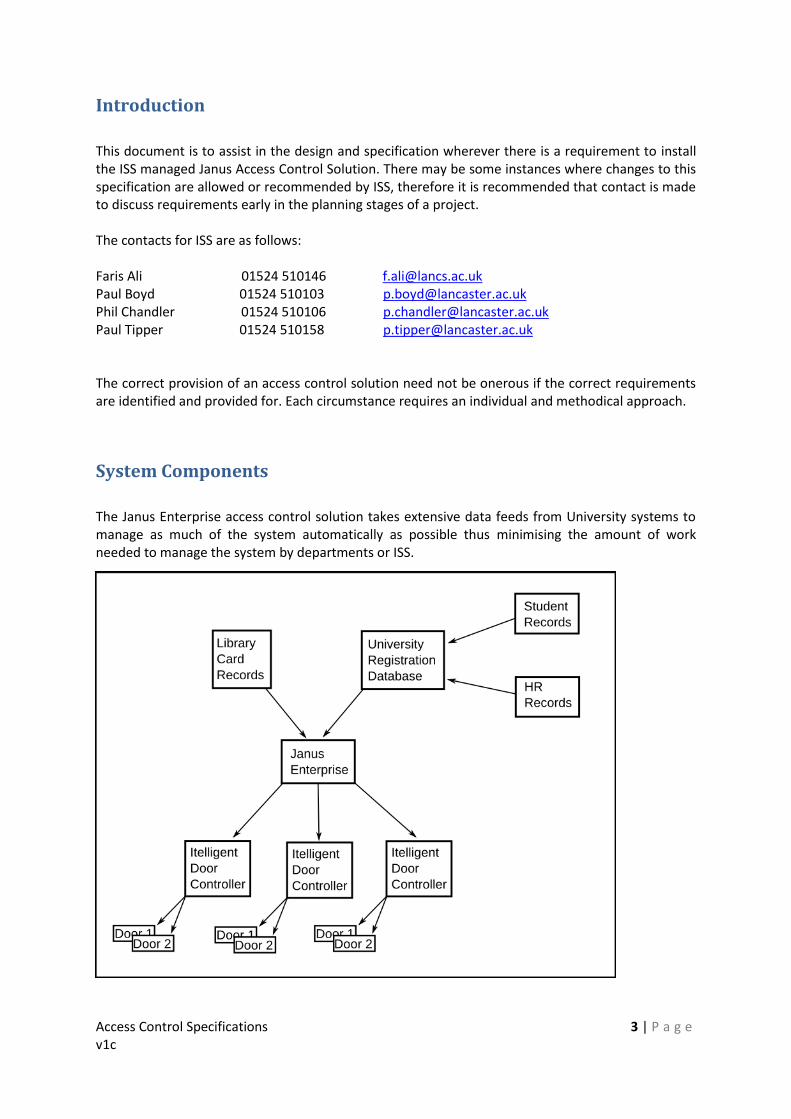
System Components
The Janus Enterprise access control solution takes extensive data feeds from University systems to manage as much of the system automatically as possible thus minimising the amount of work needed to manage the system by departments or ISS.
Access Control Specifications v1c
4 | P a g e
Intelligent Door Controller Ethernet (lDCe) An Intelligent Door Controller (IDC) is capable of controlling either two doors with a single reader each, or a single door with up to two readers. Each IDC should be utilised for two doors where possible to minimise the associated licensing costs involved rather than installing two separate controllers. By default, the IDC can support up to twelve thousand card records, but this must be halved for Lancaster to account for the dual technology nature of the University library card. A memory expansion module must be added to the controller to extend its capacity. The Ethernet version of a Grosvenor IDC must be used for all installations.
Reader Groups, Access Groups and Time Zones Each reader is assigned to a reader group. Each user (and thus access tokens associated with that user) is assigned one or more access groups. These are then linked via a time zone record to create the access rights. Given the following: Access groups: A, B, Medical Students Reader groups: Learning Zone, Graduate PC Lab, Medical School Time zones: All the time, Mon to Fri – 08:00 to 18:00 This is best illustrated by an example as a two dimensional grid.
A B Medical Students
Learning Zone All the time All the time
Graduate PC Lab All the time All the time
Medical School Mon – Fri 08:00 – 18:00
Membership of access groups is determined by records within the User Registration Database (URD) which is fed by student records and human resources data systems. Membership of groups is not maintained by ISS but by the departments and the student registry.

Access Control Specifications v1c
5 | P a g e
Security and Implementation Considerations
Area Perimeter Fire Doors It is recommended that area perimeter fire doors be fitted with suitable alarms such as exit guards to discourage their misuse and subsequent potential for insecurity of an area. These individual alarms should be linked to intruder alarm systems within the building to ensure that any insecure doors are identified and subsequently secured even if operated outside of normal working hours.
Mechanical and Electrical
At all times, due consideration to future replacement must be given to access to all components for service and maintenance. The IDC must always be located in an easily accessible location without any requirement for work at height or the removal of fixed/semi fixed structures. All installations must be carried out in accordance with the manufacturers' installation instructions. IDC must not be fitted in locations such that maintenance work on the IDC would present a hazard to building users or maintenance staff e.g. above doors, below raised floors, on ceilings. ISS must always be consulted regarding the IDC location prior to commencement of installation. The mains power supply for the IDC must be provided by a switched fused spur located adjacent to the IDC, with the cable run between the two to be contained in conduit utilising double insulated three core mains cable. The mains supply must be fed into the segregated compartment within the IDC. The fused spur must be fitted with a 3A fuse. The IDC box must be firmly attached to a secure flat surface using appropriate fixings. As a minimum the four corner mounting holes must be used. The IDC box must not be mounted behind any objects that would obstruct full free access to the IDC. A single data outlet installed in accordance with the current ISS cabling specification must be located in a suitable location identified in consultation with ISS. The containment method will be agreed at the same time. The IDC must always be fitted with the manufacturer specified sealed lead acid battery, the manufacturing date must be no longer than 6 months prior to installation of the IDC. All interconnection cable between system components must be in accordance with Grosvenor specifications:
Card reader – 4 pair, max. 50m, Belden #9504
Lock – 2 core, max. distance subject to volt-drop
Alarm input/output – 2 core per device, max. 100 m, Belden #9504 The cut ends of cable sheath must be covered with Hellerman sleeving, the same sleeving must also be used to fix and insulate any unused cable cores. See Appendix A.

Access Control Specifications v1c
6 | P a g e
Cable Containment All cabling must be routed utilising containment such that maintenance work, re-cabling etc can be achieved without removal or damage to any part of the building fabric. All containment should be concealed by being plastered into walls or placed within the floor plenum or ceiling voids as appropriate. Cabling must not be directly plastered into any walls, containment must be used. Any surface mount containment must be agreed with Facilities and ISS prior to start of works. All cable knock-outs through metal enclosures shall be fitted with either compression glands or conduit as appropriate to the installation. Only one cable should be fitted per compression gland. Mains electrical cabling and low voltage cabling must not be placed within the same containment. As previously specified, at all times due consideration to replacement must be given. Accessible junction boxes should be provided within the containment at any bends further than one meter from a junction box. Containment for the secure area should not be routed into the insecure area or vice versa other than via suitable horizontal cable trays. Containment may be routed from the insecure side to the secure side if there is then separate vertical containment to the cable tray for the respective secure/insecure wiring (i.e. two back-to-back back boxes on the same wall must not directly interlink.
Reader, Break Glass and Exit Hardware Installation All reader, break glass and exit boxes should be fitted ideally at 1200mm to the centre from the finished floor level, but at no less than 900mm to the centre from the finished floor level. Standard flush mount electrical back boxes of at least 25mm depth must be used in all cases. Where two or more boxes are required they must be aligned either vertically or horizontally. All reader, break glass and exit boxes must always be installed at the opening edge of the door and not at the hinge edge in line with current disability discrimination act guidelines. The lDC to reader cable limit is 50m. Enclosures must be installed such that the cable length to the readers is within this limit. Examples of suitable hardware for reader, break glass and exit can be seen in Appendix A.

Access Control Specifications v1c
7 | P a g e
Hardware Provision
Door Contacts and Sounders All doors must be fitted with door contacts integral to the locking mechanism which provide a positive indication that the door is closed and locked. Automatic doors (building entry) which do not feature a locking mechanism must be installed with additional door contacts. A tamper proof sounder must be installed adjacent to or above the controlled door on the secure side. This will sound should the door be propped open. Buzzers as a component of a reader are not acceptable. This serves to ensure that fire doors function as intended and that security in a given area is maintained. The sounder must produce a sound level of 75dba ±10dba. Note that the sounder will be triggered from an appropriate IDC output not the from the IDC Sounder output. Please refer to Appendix A. Where separate door contacts are necessary they must be flush mount with normally open contacts, suitably positioned so that operation only occurs when the controlled door is fully closed. Door contacts must be connected to an appropriate IDC input, please refer to Appendix A. The contacts and sounder must be connected to the same numbered inputs/outputs as the controlled door number e.g. door contacts must be going to input 1 and door sounder to output 1 for the door on sub address 1.
Break glass units A resettable break glass unit is required on egress routes where a mechanical means of overriding the access control system in a conventional manner is not available (i.e. use of a magnetic lock or other locking mechanism that requires an exit switch to be operated). All break glass units must, in addition to the main contacts, be fitted with auxiliary alarm contacts. The break glass unit must be connected so as to disable the locking mechanism independent of control from the IDC. Please refer to Appendix A.
Exit switches Exit switches will generally be required to release an electronic locking mechanism that provides no mechanical release from the secure side. Please refer to Appendix A.
Fire alarm interfacing Where a mechanical means of overriding the access control system in a conventional manner is not available and where building regulations deem a fire alarm interface to be required, this should normally consist of a relay contact that goes open circuit on activation of the fire alarm and is wired in series with the lock activation circuit. Please refer to Appendix A. Any additional relays must be fitted in a suitable enclosure external to the IDC, with a conduit route between the two.

Access Control Specifications v1c
8 | P a g e
Reader specification
MiFare Classic For correct system operation ISS recommend readers should be Deister PRM5/2 (proximity only) with programming code 44150. Alternative readers may be sourced but must meet strict acceptance criteria to be specified by ISS, this will include the way in which card data is read and how the reader interacts with the control hardware. A reader stating that it is MiFare compatible is insufficient detail for acceptance - custom programming will be required for any other reader to work with the Lancaster library card and this programming may be chargeable, depending on the reader manufacturer. The reader must be connected to the same numbered sub address as the controlled door. Any alternative reader sourced must be purchased in conjunction with Grosvenor Technology endorsements to prevent any compatibility issues.
Lock specification Any door that is part of a fire exit route must fail open or have a mechanical override in accordance with current fire regulations. Unless there is a specific reason for a door to fail secure it should fail open on loss of power. If a door is required to fail secure and is powered, then additional battery backup must be provided external to the IDC. Appendix B gives the interface requirements for common types of lock. Any deviation from these interface requirements, or requests for interface requirements for different types of lock, must be agreed in advance in writing by ISS. It is recommended that unless there are overriding reasons to do otherwise, magnetic locks should be fitted to the secure side of the door to prevent tampering.
Automatic Door Systems Where automatic doors are installed, if they cannot be installed as a conventional door controlled by the IDC then ISS will interface via two dry contact pairs forming the ISS demarcation point. Any external circuitry required to interface with these pairs must be fitted in a suitable enclosure external to the IDC, with a conduit route between the two and is outside the ISS scope of responsibility.
Lift control Each lift car will be fitted with a reader that when a card is presented will indicate permitted destination floors via the lift control panel. Integration between the lift and access control hardware will need to be carefully coordinated between the lift and access control installation contractors to ensure the required functionality is provided.

Access Control Specifications v1c
9 | P a g e
Specialist hardware and software may be required at additional cost. Grosvenor Technology and the lift manufacturer must be consulted to ensure the two systems integrate correctly.
System commissioning & Handover
Following installation the system should be locally configured by the installation contractor to meet the access controls required by the building end users. Not less than 5 working days prior to commissioning the following information must be provided to ISS:
MAC address of IDCe
Exact location of IDCe (using Facilities numbering system)
Which doors are controlled by which sub channel
Full list of all connected inputs and outputs
Any agreed variations from the specifications for each door
Access groups and time periods for each door/area
The names and room numbers of access controlled areas and all the controlled doors/door numbers that give access to them
Cleaner, security and porter key bunch numbers that will service each door/area
Any day time door open periods (no swipe required)
Number of guest fobs and access requirements Prior to handover full functionality of the system must be demonstrated by the installer using local control and an ISS supplied access token. The handover inspection/demonstration will include a full functional test of all system components including but not limited to:
Door functionality on presentation of a valid/invalid token
Function of day/night mode
Correct functioning of door wedge alarm/door contacts
Exit switch and break glass operation
Wiring inspection and equipment mounting
Operation of fire alarm interface where fitted After the handover functionality demonstration the system should be left configured to acquire an IP address by DHCP. Final configuration will be carried out by ISS staff. After the handover demonstration ISS must be supplied with a copy of the 'as built' wiring diagram including colour coding of wiring used.

Access Control Specifications v1c
10 | P a g e
References JANUS Access Control http://www.grosvenortechnology.co.uk/products/janus-access-control Deister: http://www.deister.com/en/markets/security-safety/
Access Control Specifications v1c
11 | P a g e
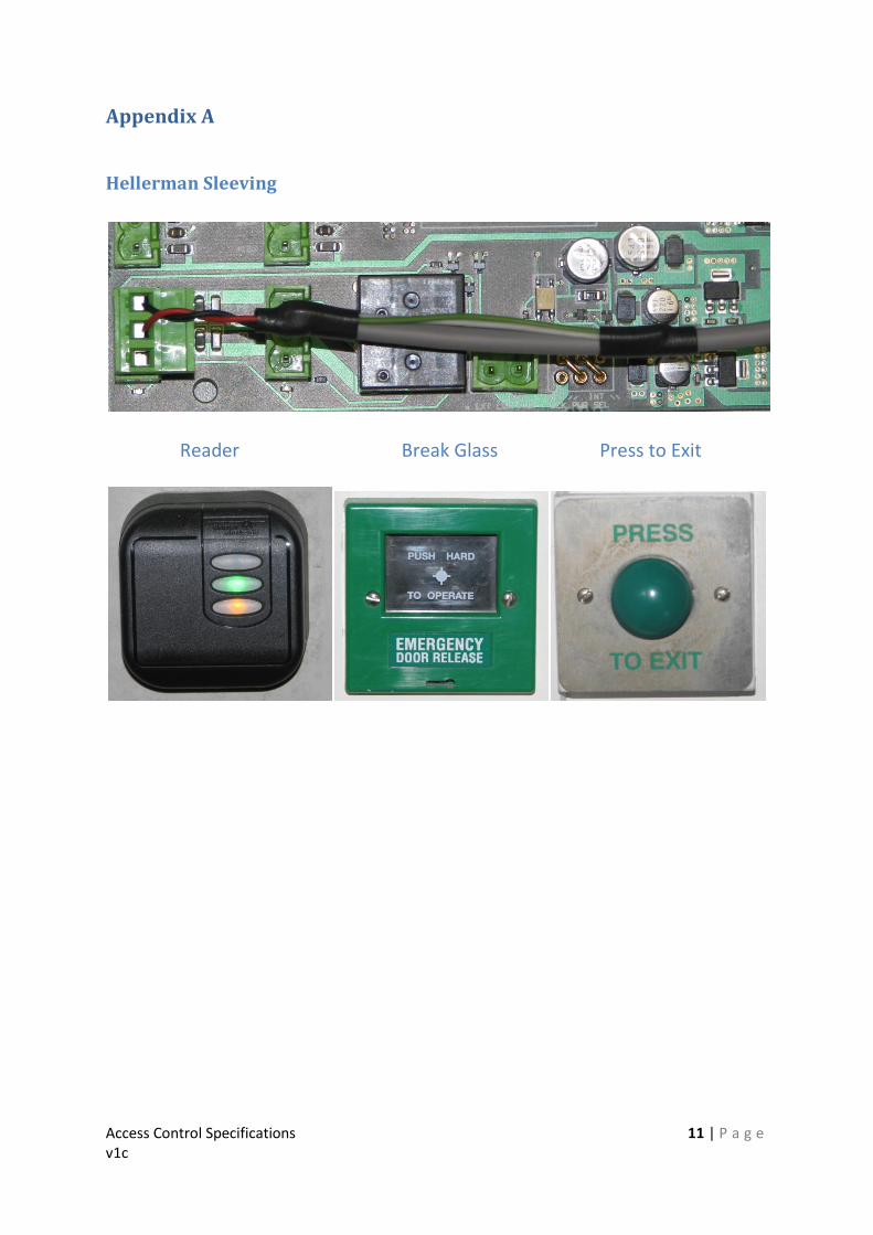
Appendix A
Hellerman Sleeving
Reader Break Glass Press to Exit
Access Control Specifications v1c
12 | P a g e
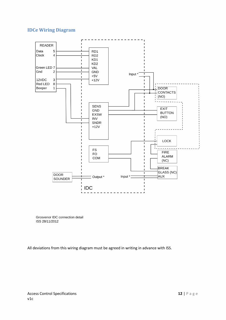
IDCe Wiring Diagram
All deviations from this wiring diagram must be agreed in writing in advance with ISS.

Access Control Specifications v1c
13 | P a g e
Appendix B - Lock Interface Parameters For a magnetic lock
ISS will supply 12VDC at 500mA, active state for door locked, inactive for door open.
ISS will receive a dry contact pair, closed circuit for door locked, open circuit for door open. For solenoid operated locks
ISS will supply, for locks that fail secure, 12VDC at 500mA, active state for door open, inactive for door locked.
ISS will supply, for locks that fail open, 12VDC at 500mA, active state for door locked, inactive for door open.
ISS will receive a dry contact pair, closed circuit for door locked, open circuit for door open. For automatic doors
ISS will supply a dry contact pair that will go closed circuit when the door is required to open.
ISS will receive a dry contact pair that will go closed circuit to signal day time mode.
Both sets of contacts described above are rated 30V AC or DC at 2A maximum.

Access Control Specifications v1c
14 | P a g e
Appendix C – Summary of Required Information Note 1: The full specification for commissioning and handover is covered in the relevant section elsewhere in this document. Supplying the following information forms only part of this process. Note: 2: The following information must be supplied to ISS at least five working days prior to commissioning for each IDC being installed.
MAC address
Exact location of IDCe (using Facilities numbering system)
Door ID connected to sub channel 1 (door 1)
Name and room number of area controlled by door 1
All inputs and outputs associated with door 1
Access groups and time periods for door 1
Door ID connected to sub channel 2 (door 2)
Name and room number of area controlled by door 2
All inputs and outputs associated with door 2
Access groups and time periods for door 2
Any agreed variations from the specifications for each door
Cleaner, security and porter key bunch numbers that will service each door/area
Any day-time door open periods (no swipe required)
Number of guest fobs and access requirements


