+ All Categories
Home > Documents > Accessories & Sensors · Accessories & Sensors Technical Reference Manual Version: 1.2.9 Thank you!...

Accessories & Sensors · Accessories & Sensors Technical Reference Manual Version: 1.2.9 Thank you!...

Date post: 01-Nov-2019
Category:
Upload: others
View: 7 times
Download: 0 times
Share this document with a friend
88
Accessories & Sensors Technical Reference Manual Version: 1.2.10 Thank you! Thank you very much for your investment in our unique data acquisition systems. These are top-quality instruments which are designed to provide you years of reliable service. This guide has been prepared to help you get the most from your investment, starting from the day you take it out of the box, and extending for years into the future. www.dewesoft.com DEWESoft® DEWESoft® DEWESoft® DEWESoft® DEWESoft® DEWESoft® DEWESoft® DEWESoft® DEWESoft® DEWESoft® DEWESoft® DEWESoft® measurement innovation measurement innovation measurement innovation measurement innovation measurement innovation measurement innovation measurement innovation
Transcript

Accessories & SensorsTechnical Reference Manual

Version: 1.2.10

Thank you!

Thank you very much for your investment in our unique data acquisition systems. These are top-quality instrumentswhich are designed to provide you years of reliable service. This guide has been prepared to help you get the most

from your investment, starting from the day you take it out of the box, and extending for years into the future.

www.dewesoft.com

DEWESoft® DEWESoft® DEWESoft® DEWESoft® DEWESoft® DEWESoft® DEWESoft® DEWESoft® DEWESoft® DEWESoft® DEWESoft® DEWESoft®

measurement innovation measurement innovation measurement innovation measurement innovation measurement innovation measurement innovation measurement innovation

Table Of Contents

Table Of Contents1 Notice................................................................................................................................................................................1

1.1 Safety instructions....................................................................................................................................................22 About this document.........................................................................................................................................................7

2.1 Legend......................................................................................................................................................................72.2 Online versions........................................................................................................................................................8

2.2.1 Technical reference manual.............................................................................................................................83 DSI® Adapters..................................................................................................................................................................9

3.1 DSI Overview..........................................................................................................................................................93.2 DSI: General Specifications...................................................................................................................................10

3.2.1 Calibration.....................................................................................................................................................103.2.2 DSI: Pin-out...................................................................................................................................................103.2.3 Environmental...............................................................................................................................................10

3.3 DSI-TH-x...............................................................................................................................................................113.3.1 DSI-TH-x Specifications...............................................................................................................................123.3.2 DSI-TH Input Connection.............................................................................................................................13

3.4 DSI-ACC................................................................................................................................................................143.4.1 DSI-ACC Specifications...............................................................................................................................153.4.2 DSI-ACC Input Connection..........................................................................................................................15

3.5 DSI-CHG-50..........................................................................................................................................................163.5.1 DSI-CHG-x Specifications............................................................................................................................173.5.2 DSI-CHG Input Connection..........................................................................................................................17

3.6 DSI-V-200..............................................................................................................................................................183.6.1 DSI-V-200 Specifications.............................................................................................................................193.6.2 DSI-V-200 Input Connection........................................................................................................................19

3.7 DSI-RTD................................................................................................................................................................203.7.1 DSI-RTD Specifications................................................................................................................................213.7.2 DSI-RTD Input Connection...........................................................................................................................22

3.8 DSI-20mA..............................................................................................................................................................233.8.1 DSI-20mA Specifications..............................................................................................................................233.8.2 DSI-20mA Input Connection.........................................................................................................................233.8.3 DSI-20mA Output Connector........................................................................................................................233.8.4 DSI-20mA Assembly.....................................................................................................................................24

3.9 MSI-5A..................................................................................................................................................................253.9.1 MSI-5A Specifications..................................................................................................................................253.9.2 MSI-5A Input Connection.............................................................................................................................253.9.3 MSI-5A Output Connector............................................................................................................................253.9.4 MSI-5A Adapter............................................................................................................................................26

4 DS Battery Packs............................................................................................................................................................274.1 Specifications.........................................................................................................................................................274.2 DS-BP2i: Battery Pack...........................................................................................................................................27

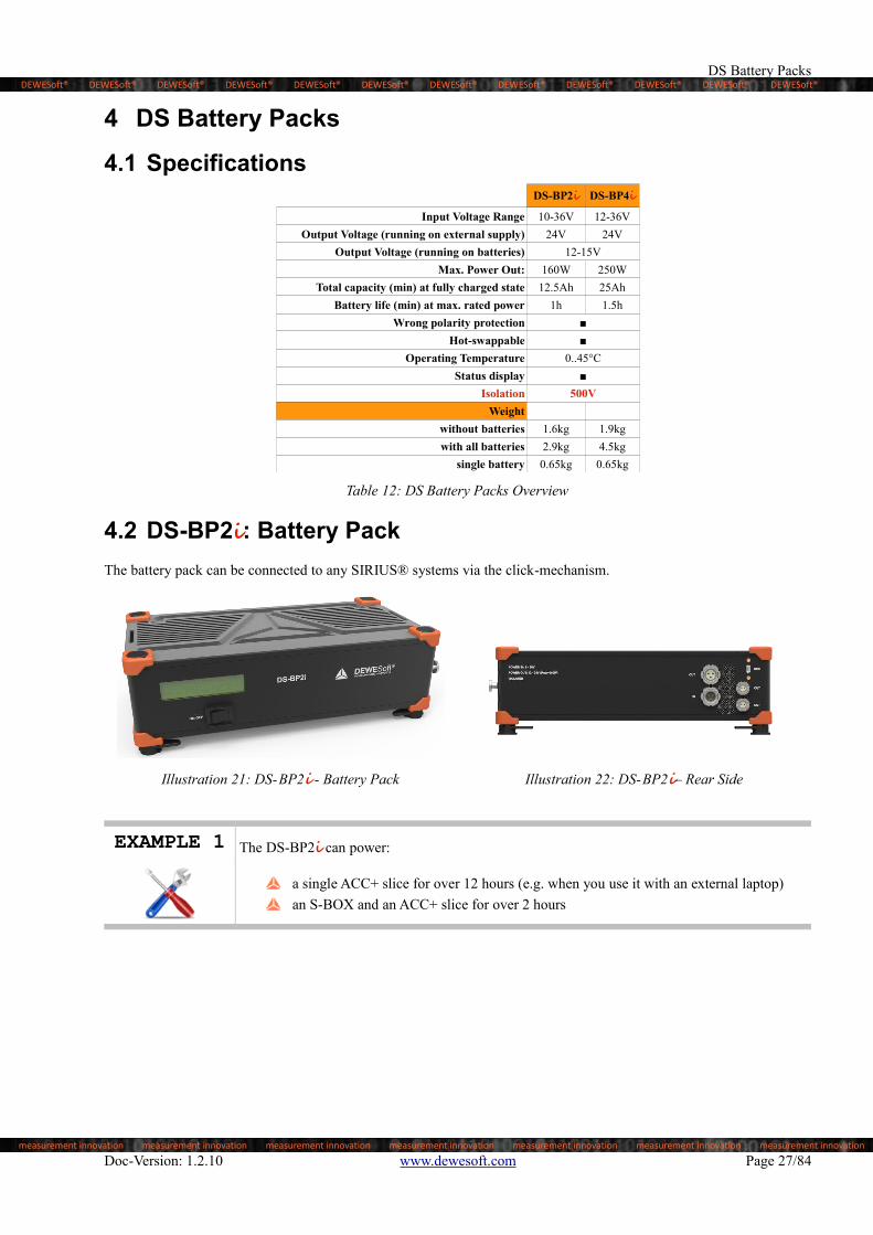
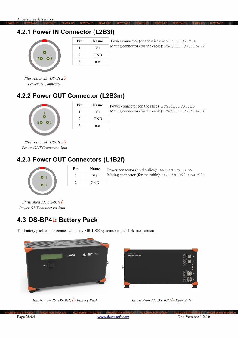
4.2.1 Power IN Connector (L2B3f)........................................................................................................................284.2.2 Power OUT Connector (L2B3m)..................................................................................................................284.2.3 Power OUT Connectors (L1B2f)..................................................................................................................28

4.3 DS-BP4i: Battery Pack...........................................................................................................................................284.3.1 Power IN Connector (L2B2m)......................................................................................................................294.3.2 Power OUT Connector (L2B2f)....................................................................................................................294.3.3 Power OUT Connectors (L1B2f)..................................................................................................................29

4.4 Dimensions.............................................................................................................................................................305 Sensors............................................................................................................................................................................31

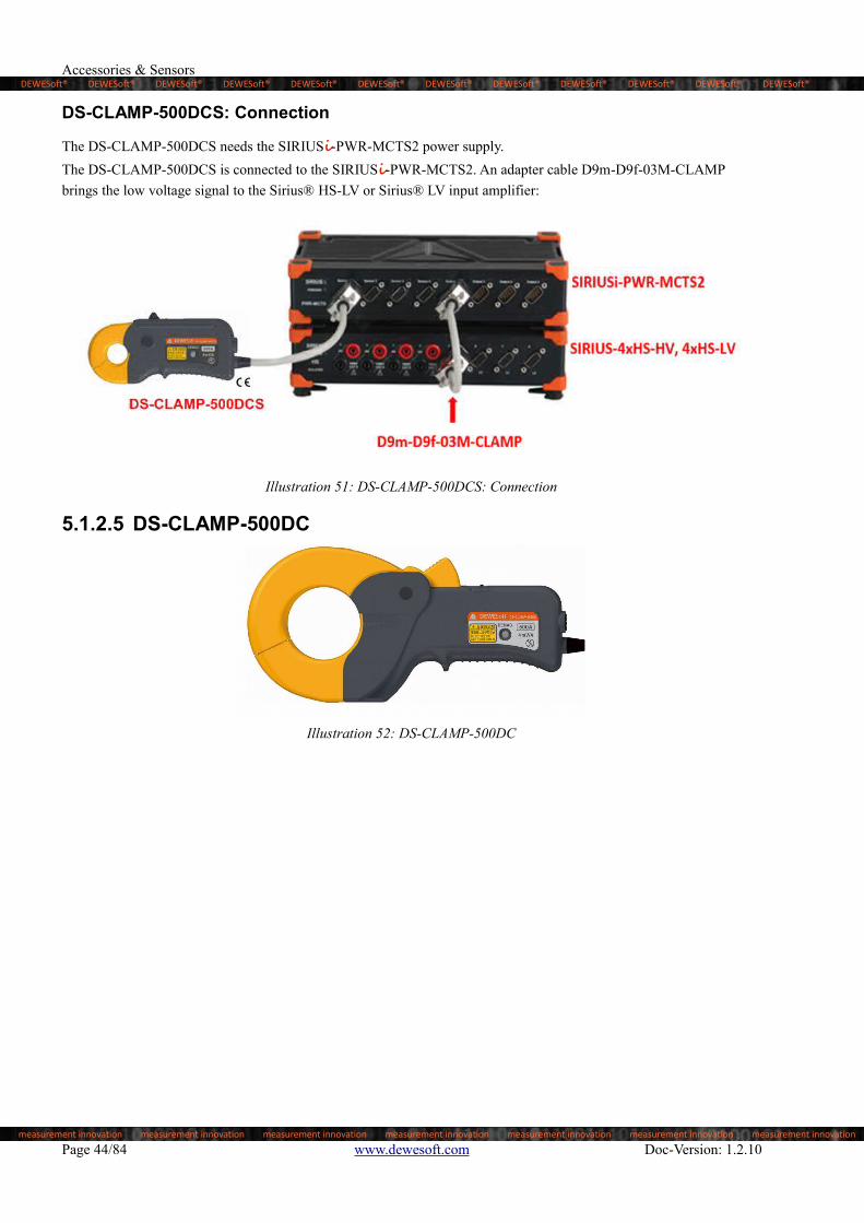
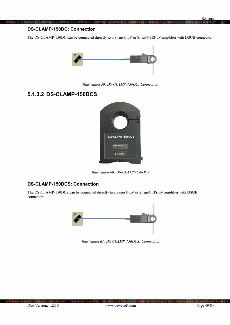
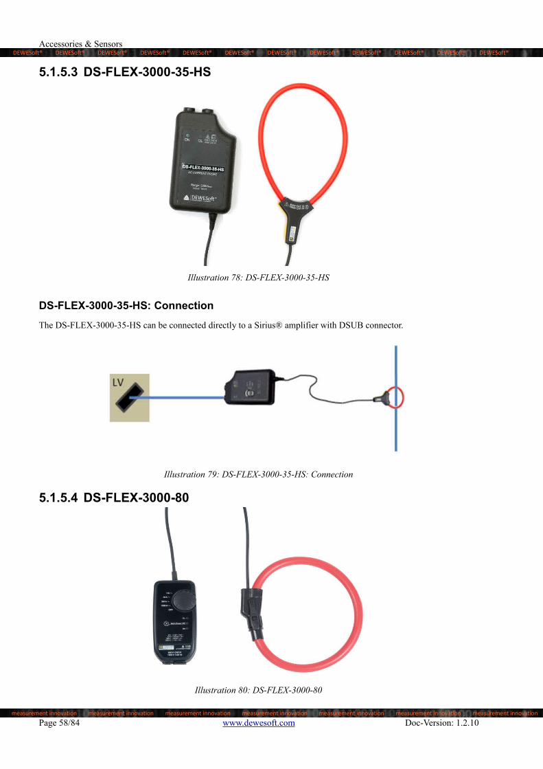
5.1 Current Clamps......................................................................................................................................................315.1.1 Zero-Flux Transducers..................................................................................................................................315.1.2 DC CLAMPS Flux Gate Technology............................................................................................................395.1.3 DC CLAMPS Hall Effect Technology..........................................................................................................475.1.4 AC CLAMPS.................................................................................................................................................525.1.5 FLEX.............................................................................................................................................................565.1.6 Isolated Current Transducers.........................................................................................................................605.1.7 Shunts............................................................................................................................................................61

Page I

DEWESoft® DEWESoft® DEWESoft® DEWESoft® DEWESoft® DEWESoft® DEWESoft® DEWESoft® DEWESoft® DEWESoft® DEWESoft® DEWESoft®

measurement innovation measurement innovation measurement innovation measurement innovation measurement innovation measurement innovation measurement innovation

Accessories & Sensors

5.2 DS-TACHOx..........................................................................................................................................................625.2.1 DS-TACHO2.................................................................................................................................................625.2.2 DS-TACHO3.................................................................................................................................................64

6 MSI Adapters..................................................................................................................................................................676.1 MSI Overview........................................................................................................................................................676.2 General Specifications...........................................................................................................................................67

6.2.1 Calibration.....................................................................................................................................................676.2.2 Pin-out...........................................................................................................................................................686.2.3 Environmental...............................................................................................................................................68

6.3 MSI-TH-x...............................................................................................................................................................696.3.1 MSI-TH-x Specifications..............................................................................................................................706.3.2 MSI-TH Input Connection............................................................................................................................71

6.4 MSI-ACC...............................................................................................................................................................726.4.1 MSI-ACC Specifications...............................................................................................................................736.4.2 MSI-ACC Input Connection.........................................................................................................................73

6.5 MSI-CHG-x...........................................................................................................................................................746.5.1 MSI-CHG-x Specifications...........................................................................................................................756.5.2 MSI-CHG Input Connection.........................................................................................................................75

6.6 MSI-V-200.............................................................................................................................................................766.6.1 MSI-V-200 Specifications.............................................................................................................................776.6.2 MSI-V-200 Input Connection.......................................................................................................................77

6.7 MSI-RTD...............................................................................................................................................................786.7.1 MSI-RTD Specifications...............................................................................................................................786.7.2 MSI-RTD Input Connection..........................................................................................................................79

7 Appendix.........................................................................................................................................................................817.1 Glossary and abbreviations....................................................................................................................................817.2 Documentation version history..............................................................................................................................84

Page II

DEWESoft® DEWESoft® DEWESoft® DEWESoft® DEWESoft® DEWESoft® DEWESoft® DEWESoft® DEWESoft® DEWESoft® DEWESoft® DEWESoft®

measurement innovation measurement innovation measurement innovation measurement innovation measurement innovation measurement innovation measurement innovation

Notice

1 NoticeThe information contained in this document is subject to change without notice.

CAUTION Dewesoft GmbH. shall not be liable for any errors contained in this document.Dewesoft MAKES NO WARRANTIES OF ANY KIND WITH REGARD TO THIS DOCUMENT, WHETHER EXPRESS OR IMPLIED.DEWESOFT SPECIFICALLY DISCLAIMS THE IMPLIED WARRANTIES OF MERCHANTABILITY AND FITNESS FOR A PARTICULAR PURPOSE.Dewesoft shall not be liable for any direct, indirect, special, incidental, or consequential damages, whether based on contract, tort, or any other legal theory, in connection with the furnishing of this document or the use of the information in this document.

Warranty Information:

A copy of the specific warranty terms applicable to your Dewesoft product and replacement parts can be obtained from your local sales and service office.

To find a local dealer for your country, please visit this link: http://www.dewesoft.com/support and scroll down to the Worldwide distributors list to find a dealer in your country or region.

Calibration

Every instrument needs to be calibrated at regular intervals. The standard norm across nearly every industry is annual calibration. Before your Dewesoft data acquisition system is delivered, it is calibrated. Detailed calibration reports for your Dewesoft system can be requested. We retain them for at least one year, after system delivery.

Support

Dewesoft has a team of people ready to assist you if you have any questions or any technical difficulties regarding the system. For any support please contact your local distributor first or Dewesoft directly.

Austria Slovenia

Dewesoft GmbHGrazerstrasse 7A-8062 KumbergAustria / Europe

Tel.: +43 3132 2252Fax: +43 3132 2252-2

Web: http://www.dewesoft.com

The telephone hotline is availableMonday to Thursday between09:00-12:00 (GMT +1:00)13:00-17:00 (GMT +1:00) Friday:09:00-13:00 (GMT +1:00)

Dewesoft d.o.o.Gabrsko 11a1420 TrbovljeSlovenia / Europe

Tel.: +386 356 25 300Fax: +386 356 25 301

Web: http://www.dewesoft.com

The telephone hotline is availableMonday to Friday between08:00 and 16:00 CET (GMT +1:00)

Service/repairs

The team of Dewesoft also performs any kinds of repairs to your system to assure a safe and proper operation in the future. For information regarding service and repairs please contact your local distributor first or Dewesoft directly.

Doc-Version: 1.2.10 www.dewesoft.com Page 1/84

DEWESoft® DEWESoft® DEWESoft® DEWESoft® DEWESoft® DEWESoft® DEWESoft® DEWESoft® DEWESoft® DEWESoft® DEWESoft® DEWESoft®

measurement innovation measurement innovation measurement innovation measurement innovation measurement innovation measurement innovation measurement innovation

Accessories & Sensors

Restricted Rights Legend:

Use Austrian law for duplication or disclosure.

Dewesoft GmbHGrazerstrasse 7A-8062 KumbergAustria / Europe

Printing History:

Version 1.2.10 Revision 278Released 2015Last changed: 2. December 2019 10:03

Copyright

Copyright © 2015-2019 Dewesoft GmbH

This document contains information which is protected by copyright. All rights are reserved. Reproduction, adaptation, or translation without prior written permission is prohibited, except as allowed under the copyright laws.

All trademarks and registered trademarks are acknowledged to be the property of their owners.

1.1 Safety instructions

Your safety is our primary concern! Please be safe!

Safety symbols in the manual

WARNING

Calls attention to a procedure, practice, or condition that could cause body injury or death.

CAUTIONCalls attention to a procedure, practice, or condition that could possibly cause damage to equipment or permanent loss of data.

General Safety Instructions

WARNING The following general safety precautions must be observed during all phases of operation, service, and repair of this product. Failure to comply with these precautions or with specific warnings elsewhere in this manual violates safety standards of design, manufacture, and intended use of the product. Dewesoft GmbH assumes no liability for the customer’s failure tocomply with these requirements.

Page 2/84 www.dewesoft.com Doc-Version: 1.2.10

DEWESoft® DEWESoft® DEWESoft® DEWESoft® DEWESoft® DEWESoft® DEWESoft® DEWESoft® DEWESoft® DEWESoft® DEWESoft® DEWESoft®

measurement innovation measurement innovation measurement innovation measurement innovation measurement innovation measurement innovation measurement innovation

Notice

All accessories shown in this document are available as option and will not be shipped as standard parts.

Environmental Considerations

Information about the environmental impact of the product.

Product End-of-Life Handling

Observe the following guidelines when recycling a Dewesoft system:

System and Components Recycling

Production of these components required the extraction and use of natural resources. The substances contained in the system could be harmful to your health and to the environment if the system is improperly handled at it's end of life! Please recycle this product in an appropriate way to avoid an unnecessary pollution of the environment and to keep natural resources.

This symbol indicates that this system complies with the European Union’s requirements according to Directive 2002/96/EC on waste electrical and electronic equipment (WEEE). Pleasefind further information about recycling on the Dewesoft web sitewww.dewesoft.com

Restriction of Hazardous Substances

This product has been classified as Monitoring and Control equipment, and is outside the scope of the 2002/95/EC RoHS Directive. However we take care about our environment and the product is lead free.

General safety and hazard warnings for all Dewesoft systems

Safety of the operator and the unit depend on following these rules

Use this system under the terms of the specifications only to avoid any possible danger.

Read your manual before operating the system.

Observe local laws when using the instrument.

DO NOT touch internal wiring!

DO NOT use higher supply voltage than specified!

Use only original plugs and cables for harnessing.

You may not connect higher voltages than rated to any connectors.

The power-cable and -connector serve as Power-Breaker. The cable must not exceed 3 meters, disconnect function must be possible without tools.

Maintenance must be executed by qualified staff only.

During the use of the system, it might be possible to access other parts of a more comprehensive system.Please read and follow the safety instructions provided in the manuals of all other components regarding warning and security advices for using the system.

With this product, only use the power cable delivered or defined for the host country.

DO NOT connect or disconnect sensors, probes or test leads, as these parts are connected to a voltage supply unit.

Ground the equipment: For Safety Class 1 equipment (equipment having a protective earth terminal), a non interruptible safety earth ground must be provided from the mains power source to the product input wiring terminals.

Please note the characteristics and indicators on the system to avoid fire or electric shocks. Before connecting the system, please read the corresponding specifications in the product manual carefully.

Doc-Version: 1.2.10 www.dewesoft.com Page 3/84

DEWESoft® DEWESoft® DEWESoft® DEWESoft® DEWESoft® DEWESoft® DEWESoft® DEWESoft® DEWESoft® DEWESoft® DEWESoft® DEWESoft®

measurement innovation measurement innovation measurement innovation measurement innovation measurement innovation measurement innovation measurement innovation

Accessories & Sensors

The inputs must not, unless otherwise noted (CATx identification), be connected to the main circuit of categoryII, III and IV.

The power cord separates the system from the power supply. Do not block the power cord, since it has to be accessible for the users.

DO NOT use the system if equipment covers or shields are removed.

If you assume the system is damaged, get it examined by authorised personnel only.

Adverse environmental conditions are:

Moisture or high humidity

Dust, flammable gases, fumes or dissolver

Thunderstorm or thunderstorm conditions (except assembly PNA)

Electrostatic fields, et cetera.

The measurement category can be adjusted depending on module configuration.

Any other use than described above may damage your system and is attended with dangers like short-circuit, fire or electric shocks.

The whole system must not be changed, rebuilt or opened

DO NOT operate damaged equipment: Whenever it is possible that the safety protection features built into this product have been impaired, either through physical damage, excessive moisture, or any other reason, REMOVE POWER and do not use the product until safe operation can be verified by service-trained personnel. If necessary, return the product to Dewesoft sales and service office for service and repair to ensure that safety features are maintained.

DO NOT service or adjust alone. Do not attempt internal service or adjustment unless another person, capable of rendering first aid and resuscitation, is present.

If you assume a more risk less use is not provided any more, the system has to be rendered inoperative and should be protected against inadvertent operation. It is assumed that a more risk less operation is not possible any more, if

the system is damaged obviously or causes strange noises.

the system does not work any more.

the system has been exposed to long storage in adverse environmental.

the system has been exposed to heavy shipment strain.

DO NOT touch any exposed connectors or components if they are live wired. The use of metal bare wires is not allowed. There is a risk of short cut and fire hazard!

Warranty void if damages caused by disregarding this manual. For consequential damages NO liability will be assumed!

Warranty void if damages to property or persons caused by improper use or disregarding the safety instructions.

Unauthorized changing or rebuilding the system is prohibited due to safety and permission reasons (CE).

Be careful with voltages >25 VAC or >35 VDC! These voltages are already high enough in order to get a perilous electric shock by touching the wiring.

The product heats during operation. Make sure there is adequate ventilation. Ventilation slots must not be covered!

Only fuses of the specified type and nominal current may be used. The use of patched fuses is prohibited.

Prevent using metal bare wires! Risk of short circuit and fire hazard!

DO NOT use the system before, during or shortly after a thunderstorm (risk of lightning and high energy over-voltage). An advanced range of application under certain conditions is allowed with therefore designed products only. For details please refer to the specifications.

Make sure that your hands, shoes, clothes, the floor, the system or measuring leads, integrated circuits and so on, are dry.

DO NOT use the system in rooms with flammable gases, fumes or dust or in adverse environmental conditions.

Avoid operation in the immediate vicinity of:

high magnetic or electromagnetic fields

transmitting antennas or high-frequency generators

Page 4/84 www.dewesoft.com Doc-Version: 1.2.10

DEWESoft® DEWESoft® DEWESoft® DEWESoft® DEWESoft® DEWESoft® DEWESoft® DEWESoft® DEWESoft® DEWESoft® DEWESoft® DEWESoft®

measurement innovation measurement innovation measurement innovation measurement innovation measurement innovation measurement innovation measurement innovation

Notice

for exact values please refer to enclosed specifications.

Use measurement leads or measurement accessories aligned to the specification of the system only. Fire hazardin case of overload!

Do not switch on the system after transporting it from a cold into a warm room and vice versa. The thereby created condensation may damage your system. Acclimatise the system unpowered to room temperature.

Do not disassemble the system! There is a high risk of getting a perilous electric shock. Capacitors still might be charged, even if the system has been removed from the power supply.

The electrical installations and equipments in industrial facilities must be observed by the security regulations and insurance institutions.

The use of the measuring system in schools and other training facilities must be observed by skilled personnel.

The measuring systems are not designed for use at humans and animals.

Please contact a professional if you have doubts about the method of operation, safety or the connection of the system.

Please be careful with the product. Shocks, hits and dropping it from already lower level may damage your system.

Please also consider the detailed technical reference manual as well as the security advices of the connected systems.

This product has left the factory in safety-related flawless and in proper condition. In order to maintain this condition and guarantee safety use, the user has to consider the security advices and warnings in this manual.

EN 61326-3-1:2008

IEC 61326-1 applies to this part of IEC 61326 but is limited to systems and equipment for industrial applications intended to perform safety functions as defined in IEC 61508 with SIL 1-3.

The electromagnetic environments encompassed by this product family standard are industrial, both indoor and outdoor,as described for industrial locations in IEC 61000-6-2 or defined in 3.7 of IEC 61326-1.Equipment and systems intended for use in other electromagnetic environments, for example, in the process industry or in environments with potentially explosive atmospheres, are excluded from the scope of this product family standard, IEC 61326-3-1.

Devices and systems according to IEC 61508 or IEC 61511 which are considered as “operationally well-tried”, are excluded from the scope of IEC 61326-3-1.

Fire-alarm and safety-alarm systems, intended for protection of buildings, are excluded from the scope of IEC 61326-3-1.

Doc-Version: 1.2.10 www.dewesoft.com Page 5/84

DEWESoft® DEWESoft® DEWESoft® DEWESoft® DEWESoft® DEWESoft® DEWESoft® DEWESoft® DEWESoft® DEWESoft® DEWESoft® DEWESoft®

measurement innovation measurement innovation measurement innovation measurement innovation measurement innovation measurement innovation measurement innovation

About this document

2 About this documentThis is the Technical Reference Manual for Accessories & Sensors Version 1.2.10. The items in this documentation maybe usable with Sirius®, Krypton™ or DEWE-43 devices.

The manual is divided into several chapters. You will find:

Overview of available accessories

Overview of available sensors

Technical specifications

2.1 LegendThe following symbols and formats will be used throughout the document.

IMPORTANTGives you an important information about a subject.Please read carefully!

HINT

Gives you a hint or provides additional information about a subject.

EXAMPLE

Gives you an example to a specific subject.

Example Meaning Description

Cancel Button a button that you can click

File Menu Item a menu item, will open a sub menu or a dialogue

Times New Roman List Item an item in a list (or tree) that you can select

Events Tab Sheet a tab sheet that you can select

C:\Program Files\OpenOffice.org 3\readme.txt

File Path and Name a file name or path

Windows Key a term any kind of term (maybe also compound)

SNR: 85dB Preliminary info Preliminary information: e.g. specifications that are not confirmed yet

Table 1: Layout formats used in the documentation

Doc-Version: 1.2.10 www.dewesoft.com Page 7/84

DEWESoft® DEWESoft® DEWESoft® DEWESoft® DEWESoft® DEWESoft® DEWESoft® DEWESoft® DEWESoft® DEWESoft® DEWESoft® DEWESoft®

measurement innovation measurement innovation measurement innovation measurement innovation measurement innovation measurement innovation measurement innovation

Accessories & Sensors

2.2 Online versions

2.2.1 Technical reference manualThe most recent version of this manual can be downloaded from our homepage:

http://www.dewesoft.com/download

In the HW Manuals section click the download link for the Accessories and Sensors manual.

The download section also includes links to the most recent versions of the manuals for the DEWESoft® measurement hardware (i.e. Sirius®, Krypton™, etc.)

Page 8/84 www.dewesoft.com Doc-Version: 1.2.10

DEWESoft® DEWESoft® DEWESoft® DEWESoft® DEWESoft® DEWESoft® DEWESoft® DEWESoft® DEWESoft® DEWESoft® DEWESoft® DEWESoft®

measurement innovation measurement innovation measurement innovation measurement innovation measurement innovation measurement innovation measurement innovation

DSI® Adapters

3 DSI® AdaptersDSI® adapters can be connected to the D-SUB 9 connectors of the following DEWESoft® measurement devices:

Sirius®

Krypton™

DEWE-43

3.1 DSI OverviewDEWESoft® Smart Interfaces (DSI®) bring an expanded level of flexibility to your measurement system.DSI-Adapters expand the functionality of many amplifier modules and enable you to use e.g. a bridge amplifier (like SIRIUS-STG) for measuring also IEPE, thermocouple, Pt100 to Pt2000, charge or voltage up to 200 V.

HINTWhen isolation is required, you must use the DSI-adapters on isolated DEWESoft® devices: e.g. Siriusi modules.

All DSI-adapters are the size of a D-SUB 9 housing, which contains the electronics as well as the sensor connector. The miniature electronics of each DSI sensor also contain a TEDS chip in which the identification, calibration and configuration data of the DSI are stored. These data are read automatically by the DEWESoft® software and are immediately applied to the channel setup.

Features of DSI adapters:

Expand functionality of bridge and voltage inputs

Automatically detected, easy channel setup in the correct engineering units

Versions for voltage, thermocouple, RTD, IEPE and charge sensors

HINTWhen using DSI® adapters, DEWESoft® can read the TEDS information of the adapter and also the TEDS information of any sensors that are connected to the adapter (the old MSI adapters could not read the TEDS of the connected adapters).

Doc-Version: 1.2.10 www.dewesoft.com Page 9/84

DEWESoft® DEWESoft® DEWESoft® DEWESoft® DEWESoft® DEWESoft® DEWESoft® DEWESoft® DEWESoft® DEWESoft® DEWESoft® DEWESoft®

measurement innovation measurement innovation measurement innovation measurement innovation measurement innovation measurement innovation measurement innovation

Accessories & Sensors

3.2 DSI: General Specifications

3.2.1 CalibrationThe DSI-adapters are calibrated at 25 °C and meet their specifications when leaving the factory.

The time interval for recalibration depends on environmental conditions. A two year calibration interval is recommended.

3.2.2 DSI: Pin-outPin Description

Illustration 1:DSI® pin-out

1 Excitation+

2 Input+

3 Sense-

4 Ground

5 n.c.

6 Sense+

7 Input-

8 Excitation-

9 TEDS

3.2.3 Environmental

IMPORTANTAll DSI® specifications within this manual are valid at 25 °C.All DSI-adapters are produced according to ISO9001 and ISO14001.

Storage Temperature -30 °C to +85 °C

Operating Temperature -5 °C to +60 °C

Relative humidity (MIL202): 0 to 95 % at 60 °C, non-condensing

RFI susceptibility ±0.5 % span error at 400 MHz, 5 W, 3 m

Table 2: DSI® Environmental Specifications

Page 10/84 www.dewesoft.com Doc-Version: 1.2.10

DEWESoft® DEWESoft® DEWESoft® DEWESoft® DEWESoft® DEWESoft® DEWESoft® DEWESoft® DEWESoft® DEWESoft® DEWESoft® DEWESoft®

measurement innovation measurement innovation measurement innovation measurement innovation measurement innovation measurement innovation measurement innovation

DSI® Adapters

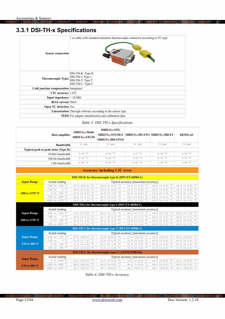
3.3 DSI-TH-xThe DSI-TH-x allows thermocouple temperature measurement with Dewesoft devices. The common thermocouple types K, J and T are supported. For high temperature application also type C is supported. A high precision cold junction compensation is included in the adapter.

The non-linearity of the thermocouple is compensated for in software. A TEDS chip provides automatic adapter identification by software and the calibration data.

In operation with the isolated SIRIUSi modules you will get a fully isolated thermocouple amplifier. In operation with

the differential SIRIUS® modules (or Krypton™/DEWE-43) only isolated thermocouples should be used, because the thermocouple input is single ended.

Illustration 2: Basic circuit design of DSI-TH-x

Doc-Version: 1.2.10 www.dewesoft.com Page 11/84

DEWESoft® DEWESoft® DEWESoft® DEWESoft® DEWESoft® DEWESoft® DEWESoft® DEWESoft® DEWESoft® DEWESoft® DEWESoft® DEWESoft®

measurement innovation measurement innovation measurement innovation measurement innovation measurement innovation measurement innovation measurement innovation

Accessories & Sensors

3.3.1 DSI-TH-x Specifications

Sensor connection

1 m cable with standard miniature thermocouple connector according to TC type

Thermocouple Types

DSI-TH-K: Type KDSI-TH-J: Type JDSI-TH-T: Type TDSI-TH-C: Type C

Cold junction compensation Integrated

CJC accuracy 1.0°C

Input impedance > 10 MΩ

BIAS current 50nA

Open TC detection Yes

Linearisation Through software according to the sensor type

TEDS For adapter identification and calibration data

Table 3: DSI-TH-x Specifications

Host amplifierSIRIUSx-Multi

SIRIUSx-STGM

SIRIUSx-STG

SIRIUSx-STGMv2

SIRIUSx-HD-STGS

SIRIUSx-HS-STG SIRIUSx-HD-LV DEWE-43

Bandwidth 70 kHz 70 kHz 70 kHz 70 kHz 70 kHz

Typical peak to peak noise (Type K)

30 kHz bandwidth 0.44 °C 0.44 °C 0.5 °C 0.44 °C 0.44 °C

100 Hz bandwidth 0.22 °C 0.22 °C 0.25 °C 0.22 °C 0.22 °C

1 Hz bandwidth 0.02 °C 0.02 °C 0.02 °C 0.02 °C 0.02 °C

Accuracy including CJC error

DSI-TH-K for thermocouple type K (DIN EN 60584-1)

Input Range Actual reading Typical accuracy [maximum accuracy]

-200 to 1370 °C

-200 to -100 °C ±7.0 [±12.0] °C ±4.6 [± 9.0] °C ±4.6 [± 9.0] °C ±4.6 [± 9.0] °C ±4.6 [± 9.0] °C

-100 to 0 °C ±2.6 [± 6.6] °C ±2.4 [± 4.6] °C ±2.4 [± 4.6] °C ±2.4 [± 4.6] °C ±2.4 [± 4.6] °C

0 to 500 °C ±2.0 [± 5.5] °C ±1.8 [± 3.5] °C ±1.8 [± 3.5] °C ±1.9 [± 3.5] °C ±1.9 [± 3.5] °C

500 to 1000 °C ±2.1 [± 6.1] °C ±2.1 [± 4.1] °C ±2.1 [± 4.1] °C ±2.5 [± 4.1] °C ±2.5 [± 4.1] °C

1000 to 1370 °C ±3.0 [± 7.0] °C ±2.5 [± 5.0] °C ±2.5 [± 5.0] °C ±3.0 [± 5.0] °C ±3.0 [± 5.0] °C

DSI-TH-j for thermocouple type J (DIN EN 60584-1)

Input Range

-200 to 1370 °C

Actual reading Typical accuracy [maximum accuracy]-200 to -100 °C ±4.0 [± 9.0] °C ±4.0 [± 7.0] °C ±4.0 [± 7.0] °C ±4.0 [± 7.0] °C ±4.0 [± 7.0] °C

-100 to 0 °C ±2.0 [± 5.7] °C ±1.7 [± 3.7] °C ±1.7 [± 3.7] °C ±2.0 [± 3.7] °C ±2.0 [± 3.7] °C

0 to 300 °C ±1.6 [± 5.0] °C ±1.6 [± 3.0] °C ±1.6 [± 3.0] °C ±1.6 [± 3.0] °C ±1.6 [± 3.0] °C

300 to 1000 °C ±2.0 [± 5.2] °C ±1.8 [± 3.2] °C ±1.8 [± 3.2] °C ±2.0 [± 3.2] °C ±2.0 [± 3.2] °C

DSI-TH-T for thermocouple type T (DIN EN 60584-1)

Input Range

-270 to 400 °C

Actual reading Typical accuracy [maximum accuracy]-250 to -100 °C ±7.0 [±25.0] °C ±7.0 [±19.0] °C ±7.0 [±19.0] °C ±7.0 [±19.0] °C ±7.0 [±19.0] °C

-100 to 0 °C ±1.8 [± 7.0] °C ±1.8 [± 5.0] °C ±1.8 [± 5.0] °C ±1.8 [± 5.0] °C ±1.8 [± 5.0] °C

0 to 100 °C ±1.3 [± 5.6] °C ±1.3 [± 3.6] °C ±1.3 [± 3.6] °C ±1.3 [± 3.6] °C ±1.3 [± 3.6] °C

100 to 400 °C ±1.0 [± 5.0] °C ±1.0 [± 3.0] °C ±1.0 [± 3.0] °C ±1.0 [± 3.0] °C ±1.0 [± 3.0] °C

DSI-TH-C for thermocouple type C (ASTM E988-96)

Input Range

-270 to 400 °C

Actual reading Typical accuracy [maximum accuracy] 0 to 1000 °C ±3.0 [±12.0] °C ±3.0 [± 8.0] °C ±3.0 [± 8.0] °C ±3.0 [± 8.0] °C ±3.0 [± 8.0] °C

1000 to 1600 °C ±4.0 [±11.6] °C ±4.0 [± 8.6] °C ±4.0 [± 8.6] °C ±4.0 [± 8.6] °C ±4.0 [± 8.6] °C

1600 to 2300 °C ±6.7 [±19.0] °C ±6.7 [±14.0] °C ±6.7 [±14.0] °C ±6.7 [±14.0] °C ±6.7 [±14.0] °C

Table 4: DSI-TH-x Accuracy

Page 12/84 www.dewesoft.com Doc-Version: 1.2.10

DEWESoft® DEWESoft® DEWESoft® DEWESoft® DEWESoft® DEWESoft® DEWESoft® DEWESoft® DEWESoft® DEWESoft® DEWESoft® DEWESoft®

measurement innovation measurement innovation measurement innovation measurement innovation measurement innovation measurement innovation measurement innovation

DSI® Adapters

3.3.2 DSI-TH Input Connection

Illustration 3: DSI-TH Input Connection

Doc-Version: 1.2.10 www.dewesoft.com Page 13/84

DEWESoft® DEWESoft® DEWESoft® DEWESoft® DEWESoft® DEWESoft® DEWESoft® DEWESoft® DEWESoft® DEWESoft® DEWESoft® DEWESoft®

measurement innovation measurement innovation measurement innovation measurement innovation measurement innovation measurement innovation measurement innovation

Accessories & Sensors

3.4 DSI-ACCThe DSI-ACC is designed to operate with IEPE sensors and IEPE compatible sensors (e.g. ICP®). The adapter provides a constant current source and high pass filter. Depending on the application, different excitation levels and high pass filters are available.

Illustration 4: Basic circuit design of DSI-ACC

In operation with the isolated SIRIUSi modules you will get a fully isolated amplifier. In operation with differential

modules (SIRIUS®, Krypton™, DEWE-43) the input configuration is single ended.

Page 14/84 www.dewesoft.com Doc-Version: 1.2.10

DEWESoft® DEWESoft® DEWESoft® DEWESoft® DEWESoft® DEWESoft® DEWESoft® DEWESoft® DEWESoft® DEWESoft® DEWESoft® DEWESoft®

measurement innovation measurement innovation measurement innovation measurement innovation measurement innovation measurement innovation measurement innovation

DSI® Adapters

3.4.1 DSI-ACC Specifications

Sensor connection BNC

Supported sensors IEPE

DSI-ACC DSI-ACC-0.16Hz DSI-ACC-20mA1

Sensor excitation 4mA ±10% 4mA ±10% 20mA ±15%

Compliance voltage > 22 Volt > 22 Volt > 20 Volt

Accuracy 30 Hz to 30 kHz 0.3%2 0.07%2 0.3%2

High pass filter 0.8 Hz 0.16 Hz 0.8 Hz

Power consumption 300 mW 300 mW 800 mW

Gain drift 50 ppm/°C

Max. input offset 12 mV

Input impedance 1 MΩ

Supply voltage ±5 V (±1 %)

Input configuration Isolated (max. 350VDC) when using with isolated SIRIUSi modules, else single ended

Bandwidth up to 500 kHz (limited by bandwidth of host amplifier)

Low-pass filter 10 Hz to 100 kHz (depending on host amplifier)

Ranges 100 mV, 1,000 mV, 10,000 mV (SIRIUS-HS series offers more ranges)

Typical SNR @ 30 kHz bandwidth

10,000 mV up to 125 dB (limited by the SNR of the host amplifier)

1,000 mV up to 110 dB (limited by the SNR of the host amplifier)

Amplifier settings automatically selected by software• Measurement: Voltage• Range: ±0.1 to ±10 V• Excitation: 10 V

Table 5: DSI-ACC-x Specifications

3.4.2 DSI-ACC Input Connection

Illustration 5: DSI-ACC Input Connection

1 Only compatible with SIRIUS-STG, SIRIUS-LV, SIRIUS-HS-STG, SIRIUS-HS-LV amplifier.2 Might be reduced through A/D card accuracy or system bandwidth

Doc-Version: 1.2.10 www.dewesoft.com Page 15/84

DEWESoft® DEWESoft® DEWESoft® DEWESoft® DEWESoft® DEWESoft® DEWESoft® DEWESoft® DEWESoft® DEWESoft® DEWESoft® DEWESoft®

measurement innovation measurement innovation measurement innovation measurement innovation measurement innovation measurement innovation measurement innovation

Accessories & Sensors

3.5 DSI-CHG-50The DSI-CHG adapter can be used for charge sensors up to 50,000 pC with Dewesoft devices.

Illustration 6: Basic circuit design of DSI-CHG

In operation with the isolated SIRIUSi modules you will get a fully isolated charge amplifier. In operation with

differential modules (SIRIUS®, Krypton™, DEWE-43) the input configuration is single ended.

Page 16/84 www.dewesoft.com Doc-Version: 1.2.10

DEWESoft® DEWESoft® DEWESoft® DEWESoft® DEWESoft® DEWESoft® DEWESoft® DEWESoft® DEWESoft® DEWESoft® DEWESoft® DEWESoft®

measurement innovation measurement innovation measurement innovation measurement innovation measurement innovation measurement innovation measurement innovation

DSI® Adapters

3.5.1 DSI-CHG-x Specifications

Sensor connection BNC

Supported sensors Charge sensors

Accuracy 0.5%

Gain drift 100 ppm/°C

Supply voltage ±5 V (±1 %)

Power consumption max. 100 mW

Input configuration Isolated (max. 350VDC) when using with isolated SIRIUSi modules, else differential

Bandwidth 0.08 Hz up to 300 kHz (limited by bandwidth of host amplifier)

Low-pass filter 10 Hz to 100 kHz (depending on host amplifier)

Range 1,000/10,000/50,000 pC (SIRIUS-HS series offers more ranges)

Typ. SNR@ 30kHz bandwidth up to 125 dB (limited by the SNR of the host amplifier)

Max. offset 20 pC (compensated in DEWESoft® by software filter)

High-pass filter 0.08 Hz 1 Hz3 10 Hz3

Amplifier settings automatically selected by software• Measurement: Voltage• Range: ±0.1 to ±10 V• Excitation: 10 V

Table 6: DSI-CHG Specifications

3.5.2 DSI-CHG Input Connection

Illustration 7: DSI-CHG Input Connection

3 Software filter

Doc-Version: 1.2.10 www.dewesoft.com Page 17/84

DEWESoft® DEWESoft® DEWESoft® DEWESoft® DEWESoft® DEWESoft® DEWESoft® DEWESoft® DEWESoft® DEWESoft® DEWESoft® DEWESoft®

measurement innovation measurement innovation measurement innovation measurement innovation measurement innovation measurement innovation measurement innovation

Accessories & Sensors

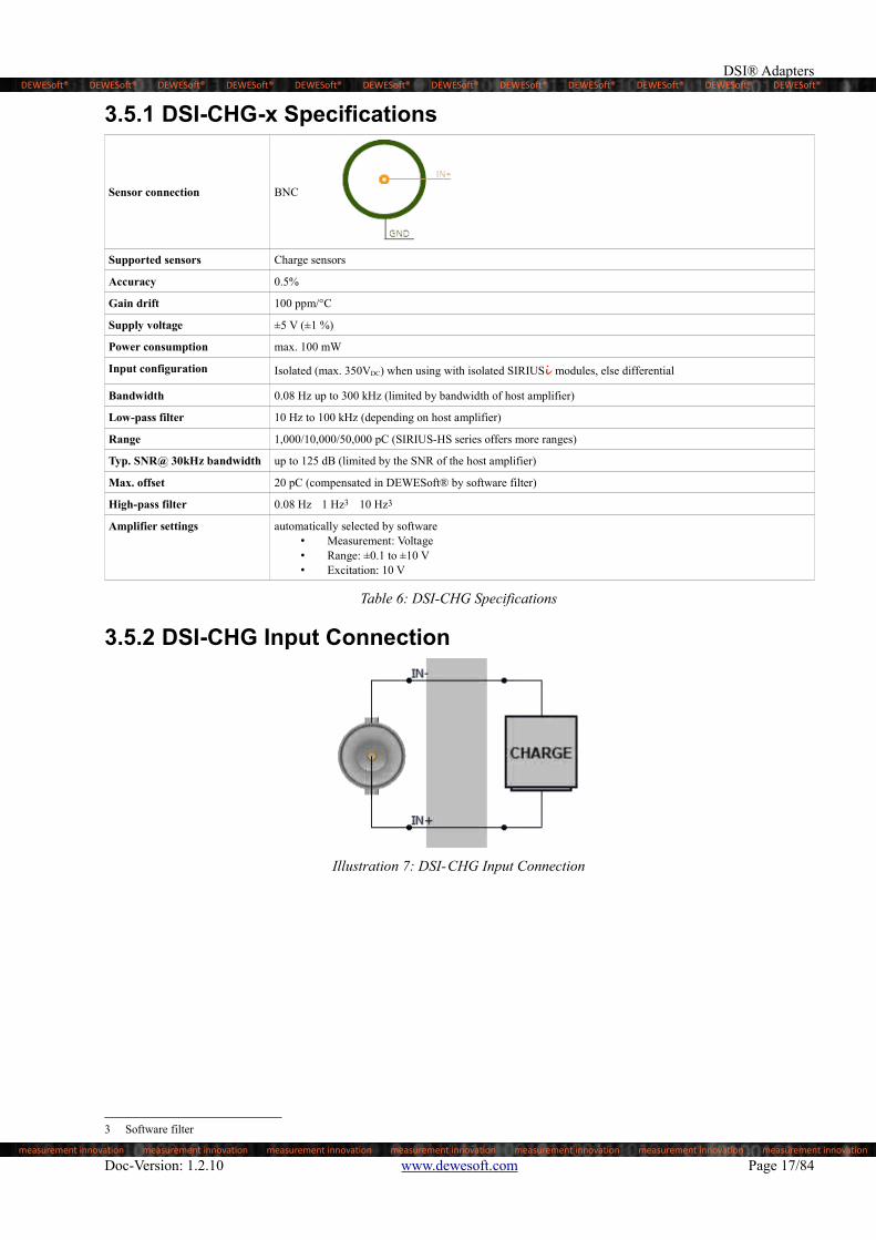
3.6 DSI-V-200Basically the adapter consist of an active voltage divider (50:1), which allows an input range up to ±200 V. The picture below shows the basic configuration of the amplifier circuit:

Illustration 8: Basic circuit design of DSI-V-200

In operation with the isolated SIRIUSi modules you will get a fully isolated amplifier. In operation with differential

modules (SIRIUS®, Krypton™, DEWE-43) the input configuration is differential.

Page 18/84 www.dewesoft.com Doc-Version: 1.2.10

DEWESoft® DEWESoft® DEWESoft® DEWESoft® DEWESoft® DEWESoft® DEWESoft® DEWESoft® DEWESoft® DEWESoft® DEWESoft® DEWESoft®

measurement innovation measurement innovation measurement innovation measurement innovation measurement innovation measurement innovation measurement innovation

DSI® Adapters

3.6.1 DSI-V-200 Specifications

Sensor connection BNC

Ranges ±200 V, ±40 V, ±4 V (SIRIUS-HS series offers more ranges)

DC Accuracy ±0.06 % of reading ±0.02 % of range ± 5mV

Bandwidth (-3dB) 300 kHz (limited by bandwidth of host amplifier)

Low-pass filter 10 Hz to 100 kHz (depending on host amplifier)

Common mode voltage range ± 200 V

Input overvoltage protection ± 250 V

Input impedance In+ 1 MΩ

Input impedance In- 1 MΩ

Gain drift Typical 15 ppm/K (max. 30 ppm/K)

Input offset drift: Typical 10 µV/K (max. 25 µV/K)

Input attenuation 50 ±0.5 % (uncalibrated)

Input configuration Isolated (max. 350VDC) when using with isolated SIRIUSi modules, else differential

Typical SNR @ 30 kHz BW 98 dB @ 200 V range98 dB @ 40 V range79 dB @ 4 V range

Host: Isolated amplifier 160 dB DC, 110 dB @ 1 kHz

Host: Differential amplifier 100 dB @ 100 Hz, 60 dB @ 10 kHz

Amplifier settings automatically selected by software• Measurement: Voltage• Range: ±0.1 to ±10 V• Excitation: 10 V

Table 7: DSI-V-200 Specifications

WARNINGFor safety reasons max. 50 V may be applied to the BNC input-connectors!Refer to the regulation of maximum allowable touch potential.

3.6.2 DSI-V-200 Input Connection

Illustration 9: DSI-V-200 Input Connection

Doc-Version: 1.2.10 www.dewesoft.com Page 19/84

DEWESoft® DEWESoft® DEWESoft® DEWESoft® DEWESoft® DEWESoft® DEWESoft® DEWESoft® DEWESoft® DEWESoft® DEWESoft® DEWESoft®

measurement innovation measurement innovation measurement innovation measurement innovation measurement innovation measurement innovation measurement innovation

Accessories & Sensors

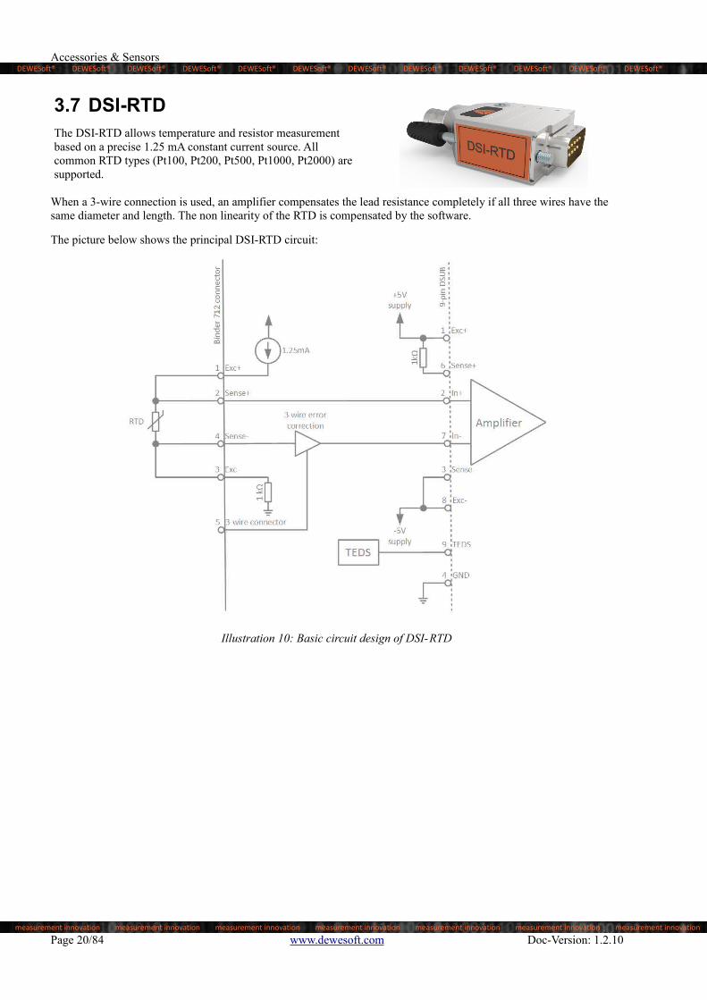
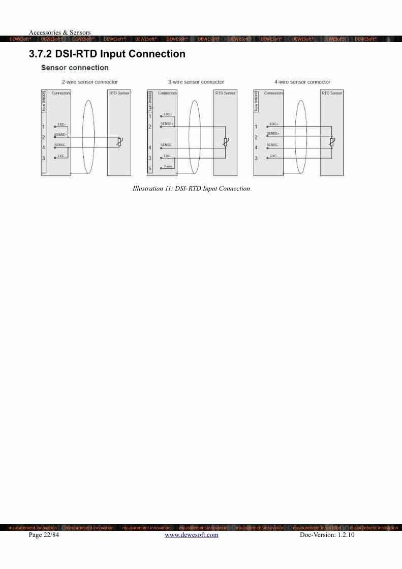
3.7 DSI-RTDThe DSI-RTD allows temperature and resistor measurement based on a precise 1.25 mA constant current source. All common RTD types (Pt100, Pt200, Pt500, Pt1000, Pt2000) are supported.

When a 3-wire connection is used, an amplifier compensates the lead resistance completely if all three wires have the same diameter and length. The non linearity of the RTD is compensated by the software.

The picture below shows the principal DSI-RTD circuit:

Illustration 10: Basic circuit design of DSI-RTD

Page 20/84 www.dewesoft.com Doc-Version: 1.2.10

DEWESoft® DEWESoft® DEWESoft® DEWESoft® DEWESoft® DEWESoft® DEWESoft® DEWESoft® DEWESoft® DEWESoft® DEWESoft® DEWESoft®

measurement innovation measurement innovation measurement innovation measurement innovation measurement innovation measurement innovation measurement innovation

DSI® Adapters

3.7.1 DSI-RTD Specifications

Sensor connection 5-pin BINDER connector series 712

Supported sensors Resistance: Pt100; Pt200; Pt500; Pt1000; Pt2000

Temperature range -200 °C to 850 °C

Input offset 50 µV

Constant current 1.25 mA

Constant current accuracy ±0.02 % from calibrated value

Constant current drift 22 ppm/ °C

Linearisation Through software according to sensor type

Connection types 2-, 3- or 4-wire

Bandwidth (-3dB) 10 kHz (limited by bandwidth of host amplifier)

Input configuration Isolated (max. 350VDC) when using with isolated SIRIUSi modules, else differential

Typ. noise: 100 Hz bandwidth 0.03 °C

Amplifier settings automatically selected by software• Measurement: Voltage• Range: ±0.1 to ±10 V• Excitation: 10 V

Table 8: DSI-RTD Specifications

Measurement Hardware

Sirius or Siriusi LVv2 / STGv2 / HS-LV / HS-STG STGMv2 / HD-LV / HD-STG Multi / STGM

Krypton STG

Other DEWE-43 / Minitaur

Resistance Range

80 Ω ±0.05 % of reading ±120 mΩ ±0.05 % of reading ±120 mΩ ±0.05 % of reading ±200 mΩ

800 Ω ±0.05 % of reading ±200 mΩ ±0.05 % of reading ±200 mΩ ±0.05 % of reading ±840 mΩ

6 kΩ ±0.05 % of reading ±840 mΩ ±0.05 % of reading ±1500 mΩ ±0.05 % of reading ±8 Ω

DIN Sensor Range Temperature

EN 60751 Pt100 -200 to 850°C ±0.1 % of reading ±0.69 °C ±0.1 % of reading ±0.69 °C ±0.1 % of reading ±2.5 °C

EN 60751 Pt200 -200 to 850°C ±0.1 % of reading ±0.44 °C ±0.1 % of reading ±0.44 °C ±0.1 % of reading ±1.2 °C

EN 60751 Pt500-200 to 850°C ±0.1 % of reading ±0.61 °C ±0.1 % of reading ±1 °C ±0.1 % of reading ±4 °C

-200 to 150°C ±0.1 % of reading ±0.28 °C ±0.1 % of reading ±0.28 °C ±0.1 % of reading ±1.2 °C

EN 60751 Pt1000 -200 to 850°C ±0.1 % of reading ±0.39 °C ±0.1 % of reading ±0.8 °C ±0.1 % of reading ±3 °C

EN 60751 Pt2000 -200 to 550°C ±0.1 % of reading ±0.29 °C ±0.1 % of reading ±0.5 °C ±0.1 % of reading ±1.5 °C

Table 9: DSI-RTD Accuracy

Doc-Version: 1.2.10 www.dewesoft.com Page 21/84

DEWESoft® DEWESoft® DEWESoft® DEWESoft® DEWESoft® DEWESoft® DEWESoft® DEWESoft® DEWESoft® DEWESoft® DEWESoft® DEWESoft®

measurement innovation measurement innovation measurement innovation measurement innovation measurement innovation measurement innovation measurement innovation

Accessories & Sensors

3.7.2 DSI-RTD Input Connection

Illustration 11: DSI-RTD Input Connection

Page 22/84 www.dewesoft.com Doc-Version: 1.2.10

DEWESoft® DEWESoft® DEWESoft® DEWESoft® DEWESoft® DEWESoft® DEWESoft® DEWESoft® DEWESoft® DEWESoft® DEWESoft® DEWESoft®

measurement innovation measurement innovation measurement innovation measurement innovation measurement innovation measurement innovation measurement innovation

DSI® Adapters

3.8 DSI-20mAThe DSI-20mA allows current measurement of up to 20mA.

3.8.1 DSI-20mA SpecificationsInput range 20mA

Shunt Resistor 50 Ω, Metal Foil

Resistor Tolerance ±0.01%

Temperature Coefficient±0.05ppm/°C typical (0°C to +60°C)±0.2ppm/°C typical (-55°C to +125°C)

Power Rating 250mW (do NOT exceed maximum rating!)

TEDS 1024Bit, 1-Wire EEPROM

Table 10: DSI-20mA Specifications

3.8.2 DSI-20mA Input Connection

Illustration 12: DSI-20mA Input Connection

3.8.3 DSI-20mA Output ConnectorPin Description

Illustration 13:3-pin Surface Mount Terminal Strips with Push-Buttons

E+ Excitation+

E- Excitation-

GND AGND

IN+ IN+

IN- IN-

Doc-Version: 1.2.10 www.dewesoft.com Page 23/84

DEWESoft® DEWESoft® DEWESoft® DEWESoft® DEWESoft® DEWESoft® DEWESoft® DEWESoft® DEWESoft® DEWESoft® DEWESoft® DEWESoft®

measurement innovation measurement innovation measurement innovation measurement innovation measurement innovation measurement innovation measurement innovation

Accessories & Sensors

3.8.4 DSI-20mA Assembly

Illustration 14: Bundle Content Illustration 15: Top Illustration 16: Bottom

Page 24/84 www.dewesoft.com Doc-Version: 1.2.10

DEWESoft® DEWESoft® DEWESoft® DEWESoft® DEWESoft® DEWESoft® DEWESoft® DEWESoft® DEWESoft® DEWESoft® DEWESoft® DEWESoft®

measurement innovation measurement innovation measurement innovation measurement innovation measurement innovation measurement innovation measurement innovation

DSI® Adapters

3.9 MSI-5AThe MSI-5A allows current measurement of up to 5A.

3.9.1 MSI-5A SpecificationsInput range 5A (dc or acrms continuous)4

Pulse load 25.00A @ 5.0sec, 120sec interval, continuous

Shunt Resistor 10mΩ

Resistor Tolerance Calibrated to ±0.01%, calibration in TEDS

Temperature Coefficient <±30ppm/°C typical (+20°C to +60°C)

Resistor dielectricwithstanding voltage

1000Vac

Input connector typeMSTB 2,5/ 3-STF-5,08Phoenix Contact, mates with MSTB 2,5/ 3-GF-5,08

Connector info 2.5mm² Nominal cross section

TEDS 1024Bit, 1-Wire EEPROM

Table 11: MSI-5A Specifications

3.9.2 MSI-5A Input ConnectionPin Name I/O Description

Illustration 17:3-pin plug

1 - I, Power Current Input -

2 + I, Power Current Input +

3 G I, Signal Analog Ground

3.9.3 MSI-5A Output Connector

Illustration 18: MSI-5A Adapter partial schematic

4 Do not exceed absolute maximum rating!

Doc-Version: 1.2.10 www.dewesoft.com Page 25/84

DEWESoft® DEWESoft® DEWESoft® DEWESoft® DEWESoft® DEWESoft® DEWESoft® DEWESoft® DEWESoft® DEWESoft® DEWESoft® DEWESoft®

measurement innovation measurement innovation measurement innovation measurement innovation measurement innovation measurement innovation measurement innovation

Accessories & Sensors

Pin Name I/O Description

Illustration 19: 9pin DSUB plug

1 OE+ I, Power Output enable +

2 Out+ O, Signal Signal Output +

3 OEsns- I, Power Output enable -

4 AGND I Analog Ground

5 Reserved I/O Reserved / Not Connected

6 OEsns+ I, Signal Output enable +

7 Out- O, Signal Signal Output -

8 OE- I, Power Output enable -

9 TEDS I/O, Signal TEDS

3.9.4 MSI-5A Adapter

Illustration 20: MSI-5A Adapter

Page 26/84 www.dewesoft.com Doc-Version: 1.2.10

DEWESoft® DEWESoft® DEWESoft® DEWESoft® DEWESoft® DEWESoft® DEWESoft® DEWESoft® DEWESoft® DEWESoft® DEWESoft® DEWESoft®

measurement innovation measurement innovation measurement innovation measurement innovation measurement innovation measurement innovation measurement innovation

DS Battery Packs

4 DS Battery Packs

4.1 SpecificationsDS-BP2i DS-BP4i

Input Voltage Range 10-36V 12-36V

Output Voltage (running on external supply) 24V 24V

Output Voltage (running on batteries) 12-15V

Max. Power Out: 160W 250W

Total capacity (min) at fully charged state 12.5Ah 25Ah

Battery life (min) at max. rated power 1h 1.5h

Wrong polarity protection ■

Hot-swappable ■

Operating Temperature 0..45°C

Status display ■

Isolation 500V

Weight

without batteries 1.6kg 1.9kg

with all batteries 2.9kg 4.5kg

single battery 0.65kg 0.65kg

Table 12: DS Battery Packs Overview

4.2 DS-BP2i: Battery Pack

The battery pack can be connected to any SIRIUS® systems via the click-mechanism.

Illustration 21: DS-BP2i - Battery Pack Illustration 22: DS-BP2i– Rear Side

EXAMPLE 1 The DS-BP2i can power:

a single ACC+ slice for over 12 hours (e.g. when you use it with an external laptop)

an S-BOX and an ACC+ slice for over 2 hours

Doc-Version: 1.2.10 www.dewesoft.com Page 27/84

DEWESoft® DEWESoft® DEWESoft® DEWESoft® DEWESoft® DEWESoft® DEWESoft® DEWESoft® DEWESoft® DEWESoft® DEWESoft® DEWESoft®

measurement innovation measurement innovation measurement innovation measurement innovation measurement innovation measurement innovation measurement innovation

Accessories & Sensors

4.2.1 Power IN Connector (L2B3f)

Illustration 23: DS-BP2iPower IN Connector

Pin Name Power connector (on the slice): ECJ.2B.303.CLAMating connector (for the cable): FGJ.2B.303.CLLD721 V+

2 GND

3 n.c.

4.2.2 Power OUT Connector (L2B3m)

Illustration 24: DS-BP2iPower OUT Connector 3pin

Pin Name Power connector (on the slice): ECG.2B.303.CLLMating connector (for the cable): FGG.2B.303.CLAD921 V+

2 GND

3 n.c.

4.2.3 Power OUT Connectors (L1B2f)

Illustration 25: DS-BP2iPower OUT connectors 2pin

Pin Name Power connector (on the slice): EXG.1B.302.HLNMating connector (for the cable): FGG.1B.302.CLAD52Z1 V+

2 GND

4.3 DS-BP4i: Battery Pack

The battery pack can be connected to any SIRIUS® systems via the click-mechanism.

Illustration 26: DS-BP4i - Battery Pack Illustration 27: DS-BP4i– Rear Side

Page 28/84 www.dewesoft.com Doc-Version: 1.2.10

DEWESoft® DEWESoft® DEWESoft® DEWESoft® DEWESoft® DEWESoft® DEWESoft® DEWESoft® DEWESoft® DEWESoft® DEWESoft® DEWESoft®

measurement innovation measurement innovation measurement innovation measurement innovation measurement innovation measurement innovation measurement innovation

DS Battery Packs

EXAMPLE 2 The DS-BP4i can power:

a single ACC+ slice for over 24 hours (e.g. when you use it with an external laptop)

an S-BOX and an ACC+ slice for over 4 hours

4.3.1 Power IN Connector (L2B2m)

Illustration 28: DS-BP4iPower IN connector 2pin

Pin Name Power connector (on the slice): ECJ.2B.302.CLAMating connector (for the cable): FGJ.2B.302.CYMD921 V+

2 GND

4.3.2 Power OUT Connector (L2B2f)

Illustration 29: DS-BP4iPower OUT connector 2pin

Pin Name Power connector (on the slice): ECG.2B.302.CLL LEMOMating connector (for the cable): FGG.2B.302.CYCD921 V+

2 GND

4.3.3 Power OUT Connectors (L1B2f)

Illustration 30: DS-BP4iPower OUT connectors 2pin

Pin Name Power connector (on the slice): EXG.1B.302.HLNMating connector (for the cable): FGG.1B.302.CLAD52Z1 V+

2 GND

Doc-Version: 1.2.10 www.dewesoft.com Page 29/84

DEWESoft® DEWESoft® DEWESoft® DEWESoft® DEWESoft® DEWESoft® DEWESoft® DEWESoft® DEWESoft® DEWESoft® DEWESoft® DEWESoft®

measurement innovation measurement innovation measurement innovation measurement innovation measurement innovation measurement innovation measurement innovation

Accessories & Sensors

4.4 Dimensions

Illustration 31: DS-BP2i - Battery Pack

Illustration 32: DS-BP4i - Battery Pack

Page 30/84 www.dewesoft.com Doc-Version: 1.2.10

DEWESoft® DEWESoft® DEWESoft® DEWESoft® DEWESoft® DEWESoft® DEWESoft® DEWESoft® DEWESoft® DEWESoft® DEWESoft® DEWESoft®

measurement innovation measurement innovation measurement innovation measurement innovation measurement innovation measurement innovation measurement innovation

Sensors

5 Sensors

5.1 Current Clamps

5.1.1 Zero-Flux TransducersIT 60-S IT 200-S IT 400-S IT 700-S IT 1000-S IN 1000-S IN 2000-S

Primary CurrentRange DC,RMS Sinus

60 A 200 A 400 A 700 A 1000 A 1000 A 2000 A

Conversation ratio 1:600 1:1000 1:2000 1:1750 1:1000 1:1500 1:2000

Overload AbilityShort Time (100ms)

300 Apk 1000 Apk 2000 Apk 3500 Apk 4000 Apk 5000 Apk 10000 Apk

Max. burden resistor(100 % of lp)

10 Ω 10 Ω 2.5 Ω 2.5 Ω 2.5 Ω 4 Ω 3.5 Ω

di/dt (accuratelyfollowed)

> 25A/µs > 100A/µs > 100A/µs > 100A/µs > 100A/µs > 100A/µs > 100A/µs

Temperature influence < 2.5 ppm/K < 2 ppm/K < 1 ppm/K < 1 ppm/K < 1 ppm/K < 0.3 ppm/K < 0.1 ppm/K

Output Ratio 100 mA @ 60 A200 mA @ 200

A200 mA @ 400

A400 mA @ 700

A1 A @ 1000 A

666 mA @ 1000 A

1 A @ 2000 A

Bandwidth (0.5% oflp)

DC…800kHz DC…500kHz DC…500kHz DC…250kHz DC…500kHz DC…440kHz DC…140kHz

Linearity <0.002 % <0.001 % <0.001 % <0.001 % <0.001 % <0.003 % <0.003 %

Offset <0.025 % <0.008 % <0.004 % <0.005 % <0.005 % <0.0012 % <0.0012 %

Frequency Influence 0.04 %/kHz 0.06 %/kHz 0.06 %/kHz 0.12 %/kHz 0.06 %/kHz 0.1 %/kHz 0.1 %/kHz

Angular Accuracy<0.025°+0.06°/k

Hz<0.025°+0.05°/k

Hz<0.025°+0.09°/k

Hz<0.025°+0.18°/k

Hz<0.025°+0.09°/k

Hz<0.01°+0.05°/k

Hz<0.01°+0.075°/k

Hz

Rated isolation voltagerms,

single isolationCAT III, polution deg.

2IEC 61010-1 standards

EN 50178 standards

2000 V1000 V

2000 V1000 V

2000 V1000 V

1600 V1000 V

300 V300 V

1000 V-

1000 V-

Test voltage 50/60 Hz,1 min

5.4kV 5.4kV 5.4kV 4.6kV 3.1kV 4.2kV 6kV

Inner diameter 26mm 26mm 26mm 30mm 30mm 38mm 70mm

Dimension 93x77x47 93x77x47 93x77x47 128x106x67 128x106x85 128x106x54 231x220x76

Supply voltage (± 5%) ±15V ±15V ±15V ±15V ±15V ±15V ±15V

Operating humidity20% to 80%

(not condensing)20% to 80%

(not condensing)20% to 80%

(not condensing)20% to 80%

(not condensing)20% to 80%

(not condensing)20% to 80%

(not condensing)20% to 80%

(not condensing)

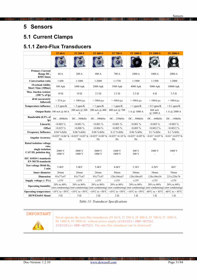
Operating temperature +10°C to +50°C +10°C to +50°C +10°C to +50°C +10°C to +50°C +10°C to +50°C -40°C to + 85°C -40°C to + 85°C

DEWESoft® Shunt 5 Ω 5 Ω 2 Ω 2 Ω 1 Ω 1 Ω 1 Ω

Table 13: Transducer Specifications

IMPORTANTNever operate the zero-flux-transducers (IT 60-S, IT 200-S, IT 400-S, IT 700-S, IT 1000-S, IN 1000-S, IN 2000-S) without power supply (SIRIUSi-PWR-MCTS2, SIRIUSir-PWR-MCTS2). The zero-flux transducer can be destroyed!

Doc-Version: 1.2.10 www.dewesoft.com Page 31/84

DEWESoft® DEWESoft® DEWESoft® DEWESoft® DEWESoft® DEWESoft® DEWESoft® DEWESoft® DEWESoft® DEWESoft® DEWESoft® DEWESoft®

measurement innovation measurement innovation measurement innovation measurement innovation measurement innovation measurement innovation measurement innovation

Accessories & Sensors

5.1.1.1 Dimensions

Illustration 33: Dimensions IT 60-S, IT 200-S and IT 400-S

Illustration 34: Dimensions IT 700-S

Illustration 35: Dimensions IT 1000-S

Over current protection

As soon as electrical saturation appears, the transducer switches from normal operation to over current mode. This electrical saturation appears in any case beyond 1.1 time the current range. Under these conditions:

the contact (operation status) between pin 8 to 3 (of D-SUB-9 connector) switches off, this contact becomes open

the green LED (located on the cover plate of the transducer and related to operation status) switches off

The over current mode remains until the primary current decreases to a value lower than a recovery current. In DEWESoft the overcurrent can be seen at digital input.

Page 32/84 www.dewesoft.com Doc-Version: 1.2.10

DEWESoft® DEWESoft® DEWESoft® DEWESoft® DEWESoft® DEWESoft® DEWESoft® DEWESoft® DEWESoft® DEWESoft® DEWESoft® DEWESoft®

measurement innovation measurement innovation measurement innovation measurement innovation measurement innovation measurement innovation measurement innovation

Sensors

5.1.1.2 SHUNT DSI-MCTS-X00-03MResistor

Technology Metal Foil

DSI-MCTS-60-03M 5 Ω / 1 Watt

DSI-MCTS-200-03M 5 Ω / 1 Watt

DSI-MCTS-400-03M 2 Ω / 1 Watt

DSI-MCTS-700-03M 2 Ω / 1 Watt

DSI-MCTS-1000-03M 1 Ω / 2 Watt

Pulse Power (5sec) 200%

Accuracy

Amplitude Accuracy ± 0.01%

Temperature Coefficient Typ: ± 2ppm/°C (max. ± 5ppm/°C)

Load Life Stability ± 0.005% @ 25°C, 2000h at rated power

Frequency Characteristics

Angular Accuracy <1° @ 500kHz

Frequency Range <0,5dB @ 1000kHz

Rise Time 1 ns

Inductance (L) max. 0.1 µH (typical 0.03µH)

Capacitance © max. 1pF (typical 0.5pF)

Tabelle 14: SHUNT DSI-MCTS-X00-03M Specifications

5.1.1.3 Amplitude and Phase Chart

Table 15: SHUNT DSI-MCTS-X00-03M Characteristics

Doc-Version: 1.2.10 www.dewesoft.com Page 33/84

DEWESoft® DEWESoft® DEWESoft® DEWESoft® DEWESoft® DEWESoft® DEWESoft® DEWESoft® DEWESoft® DEWESoft® DEWESoft® DEWESoft®

measurement innovation measurement innovation measurement innovation measurement innovation measurement innovation measurement innovation measurement innovation

Accessories & Sensors

5.1.1.4 Power Supply for Transducers

Illustration 36: Siriusir-PWR-MCTS2 (top) / Siriusi-PWR-MCTS2 (bottom)

Power Supply 9-36VDC

Max. Power Consumption 85W

Physical Dimensions [mm] 265x140x65

Operating Temperature -20 to 50°C

Storage Temperature -40 to 85°C

Humidity (@60°C) 95% RH non-condensing

Output 4x isolated power supply (1500VDC , 60sec)

Output Voltage ±15VDC

Output Power per Channel 20 W

Short Circuit Protection Indefinite (automatic recovery)

Overload protection 150% of Iout max. typical

Table 16: Siriusi-PWR-MCTS2/ Siriusir-PWR-MCTS2

Page 34/84 www.dewesoft.com Doc-Version: 1.2.10

DEWESoft® DEWESoft® DEWESoft® DEWESoft® DEWESoft® DEWESoft® DEWESoft® DEWESoft® DEWESoft® DEWESoft® DEWESoft® DEWESoft®

measurement innovation measurement innovation measurement innovation measurement innovation measurement innovation measurement innovation measurement innovation

Sensors

5.1.1.5 Connecting Zero-Flux to Sirius®

Zero-Flux to MCTS

First connect the zero-flux transducer (e.g. IT 400-S) with the D9m-D9f-5M-MCTS cable to the SIRIUSi-PWR-MCTS slice to the Sensor 1 input:

Illustration 37: Zero-Flux to MCTS connection

The D9m-D9f-5M-MCTS cable is a simple extension cable and can be used for all zero-flux transducers (60A up to 1000A).

MCTS to Sirius

Then take the corresponding DSI-MCTS-x-03M cable (where x must match the Zero-Flux transducer: e.g. for the IT-400-S, you need the DSI-MCTS-400-03M cable) and use Output 1 of the SIRIUSi-PWR-MCTS and connectit to the first LV input of the SIRIUSi-4xHS-HV,4xHS-LV slice:

Illustration 38: MCTS to Sirius® connection

Doc-Version: 1.2.10 www.dewesoft.com Page 35/84

DEWESoft® DEWESoft® DEWESoft® DEWESoft® DEWESoft® DEWESoft® DEWESoft® DEWESoft® DEWESoft® DEWESoft® DEWESoft® DEWESoft®

measurement innovation measurement innovation measurement innovation measurement innovation measurement innovation measurement innovation measurement innovation

Accessories & Sensors

Note: The DSI-MCTS-x-03M cable:only can be used for the corresponding zero-flux transducer. The cables have a built-in shunt, which must match the corresponding transducer. The following table shows which shunt cables belong tothe corresponding zero-flux transducer:

Shut Cable Zero-Flux Transducer

DSI-MCTS-60-03M IT 60-S

DSI-MCTS-200-03M IT 200-S

DSI-MCTS-400-03M IT 400-S

DSI-MCTS-700-03M IT 700-S

DSI-MCTS-1000-03M IT 1000-S, IN 1000-S, IN 2000-S

Table 17: DSI-MCTS cables

Multiple Flux-Transducers

When you have multiple Flux-Transducers you simple repeat the previous steps for each transducer. For example, whenyou use a three-phase system, in star connection, it will look like this:

Illustration 39: Three-phase system in star connection

HINT You will find how to connect voltage and current transducers to the system for different wiring configurations (DC, 1-phase, 2-phase, 3-phase delta-star-aron-V, etc.) in the DEWESoft® PRO training course “POWER ANALYSIS”http://www.dewesoft.com/pro/course/power-analysis-28

Page 36/84 www.dewesoft.com Doc-Version: 1.2.10

DEWESoft® DEWESoft® DEWESoft® DEWESoft® DEWESoft® DEWESoft® DEWESoft® DEWESoft® DEWESoft® DEWESoft® DEWESoft® DEWESoft®

measurement innovation measurement innovation measurement innovation measurement innovation measurement innovation measurement innovation measurement innovation

Sensors

5.1.1.6 DEWESoft® SetupThe DSI-MCTS-x-03M cable has an integrated TEDS chip, which stores data about scaling, calibration etc. of the zero-flux transducer. If you connect this Shunt cable to the LV input of the Sirius® slice, the configuration data are read and applied to the DEWESoft® channel setup automatically.

Settings: TEDS feature

For the automatic setup to work, you must first activate this feature in the DEWESoft® settings. Please check that the “Enable MSI adapters, TEDS sensors” check-box is activated:

Illustration 40: DEWESoft® TEDS setting

Ch. Setup

When the TEDS feature is activated, then the channel setup will immediately detect the sensor when you connect it (e.g. IT 400-S) you will see the corresponding transducer in the Ampl.name column (e.g. DSI-MCTS-400). Also notice, that the type of measurement will be changed to Current:

Illustration 41: Ch. Setup: Analog in

Doc-Version: 1.2.10 www.dewesoft.com Page 37/84

DEWESoft® DEWESoft® DEWESoft® DEWESoft® DEWESoft® DEWESoft® DEWESoft® DEWESoft® DEWESoft® DEWESoft® DEWESoft® DEWESoft®

measurement innovation measurement innovation measurement innovation measurement innovation measurement innovation measurement innovation measurement innovation

Accessories & Sensors

Channel setup

Finally, open the Setup of the individual channels, and fine-tune the remaining setting: e.g. change the channel name, set a suitable measurement range, set a low-pass filter, …

Illustration 42: Channel setup

Page 38/84 www.dewesoft.com Doc-Version: 1.2.10

DEWESoft® DEWESoft® DEWESoft® DEWESoft® DEWESoft® DEWESoft® DEWESoft® DEWESoft® DEWESoft® DEWESoft® DEWESoft® DEWESoft®

measurement innovation measurement innovation measurement innovation measurement innovation measurement innovation measurement innovation measurement innovation

Sensors

5.1.2 DC CLAMPS Flux Gate TechnologyDS-CLAMP-200DC DS-CLAMP-500DCS DS-CLAMP-500DC DS-CLAMP-1000DC

Current Range 200A DC or ACrms 500A DC or ACrms 500A DC or ACrms 1000A DC or ACrms

Sensitivity 0.01V/A 4mV/A 4mV/A 2mV/A

Bandwidth DC to 500kHz DC to 200 kHz DC to 100kHz DC to 20kHz

TEDS Fully supported Fully supported Fully supported Fully supported

Conductor PositionSensitivity5 Max. ±0.1% of reading Max. ±0.1% of reading Max. ±0.2% of reading Max. ±0.2% of reading

Zero Offset (+25°C) Max. ±10mA Max. ±250mA Max. ±250mA Max. ±50mA

Error due EarthMagnetic Field6 Max. 50mA Max. 100mA Max. 150mA Max. 150mA

Temp. Coefficient ±0.01% /°C ±0.01% /°C ±0.01% /°C ±0.01% /°C

Accuracy7 Amplitude Phase Error Amplitude Phase Error Amplitude Phase Error Amplitude Phase Error

DC±0.3% rdg.

±40mA-

±0.3% rdg.±100mA

-±0.3% rdg.±100mA

-±0.3% rdg.±200mA

-

to 100 Hz±0.3% rdg.

±20mA±0.1°

±0.3% rdg.±50mA

±0.1°±0.3% rdg.

±50mA±0.1°

±0.3% rdg.±100mA

±0.1°

100 – 500 Hz±0.3% rdg.

±40mA±0.2°

±0.3% rdg.±100mA

±0.2°±0.3% rdg.±100mA

±0.2°±0.5% rdg.±200mA

±0.2°

500 Hz – 1 kHz±0.5% rdg.

±40mA±0.5°

±0.5% rdg.±100mA

±0.5°±0.5% rdg.±100mA

±0.5°±1.0% rdg.±200mA

±0.5°

1 kHz – 5 kHz±1.0% rdg.

±40mA±1.0°

±1.0% rdg.±100mA

±1.0°±1.0% rdg.±100mA

±1.5°±2.0% rdg.±200mA

±1.5°

5 kHz – 10 kHz±1.5% rdg.

±40mA ±1.5°

±1.5% rdg.±100mA

±1.5°±1.5% rdg.±100mA

±2.0°±5.0% rdg.±500mA

±2.0°

10 kHz – 20 kHz±5% rdg.±40mA

±(0.5+0.1 f[kHz])°

±5% rdg.±100mA

±(0.5+0.1 f[kHz])°

±5% rdg.±100mA

±(0.2 f[kHz])°

±30.0% rdg.±1000mA

±10.0°20 kHz – 50 kHz±10% rdg.±250mA

50 kHz – 100 kHz±15% rdg.±100mA

±15% rdg.±250mA

±30% rdg.±250mA

100 kHz – 200 kHz ±15% rdg.±100mA

±30% rdg.±250mA

/ / / /

200 kHz – 300 kHz / / / / / /

300 kHz – 500 kHz±30% rdg.±100mA

- / / / / / /

General

Dimensions [mm] 153x67x25 153x67x25 238×116×35 238x114x35

Max. Conductor Size 20mm 20mm 50mm 50mm

Power Supply ±11V to ±15V ±11V to ±15V ±11V to ±15V ±11V to ±15V

Current Consumption Max. 6VA Max. 7VA Max. 7VA Max. 7VA

Operating EnvironmentIndoors,

Pollution Degree II,altitude up to 2000m

Indoors,Pollution Degree II,altitude up to 2000m

Indoors,Pollution Degree II,altitude up to 2000m

Indoors,Pollution Degree II,altitude up to 2000m

Operating Temp. -40°C to +85°C -40°C to +85°C -40°C to +85°C -40°C to +85°C

Operating Humidityup to 80%

(not condensing)up to 80%

(not condensing)up to 80%

(not condensing)up to 80%

(not condensing)

Safety Standards EN61010-2-032:2012

EMC Standards EN61326-1:2013

Rohs EN50581:2012 /

Table 18: DC CLAMP Flux Gate Technology: Characteristics

5 input current of 100A, DC, to 100Hz, with the use of a 10mm diameter wire6 in a DC or 60Hz magnetic field of 400 A/m7 Temperature and humidity for guaranteed accuracy is based on 0°C to 40°C; sine wave input, conductor at center position, measuring instrument

that has an input resistance of 1MΩ or higher

Doc-Version: 1.2.10 www.dewesoft.com Page 39/84

DEWESoft® DEWESoft® DEWESoft® DEWESoft® DEWESoft® DEWESoft® DEWESoft® DEWESoft® DEWESoft® DEWESoft® DEWESoft® DEWESoft®

measurement innovation measurement innovation measurement innovation measurement innovation measurement innovation measurement innovation measurement innovation

Accessories & Sensors

5.1.2.1 Frequency derating curves

Illustration 43: Frequency derating curve DS-CLAMP-200DC

Illustration 44: Frequency derating curve DS-CLAMP-500DCS

Illustration 45: Frequency derating curve DS-CLAMP-500DC

5.1.2.2 Measurement procedure (Typ: Flux Gate Technology)

At the start of measurement

1. Connect the device to the product with which you wish to use it. (while that product's power is off)

2. Turn of the product with which you wish to use the device

Page 40/84 www.dewesoft.com Doc-Version: 1.2.10

DEWESoft® DEWESoft® DEWESoft® DEWESoft® DEWESoft® DEWESoft® DEWESoft® DEWESoft® DEWESoft® DEWESoft® DEWESoft® DEWESoft®

measurement innovation measurement innovation measurement innovation measurement innovation measurement innovation measurement innovation measurement innovation

Sensors

3. Perform zero-adjustment (0 ADJ) or demagnetization (DEMAG) as necessary. (See “Demagnetization (DEMAG) and zero-adjustment (0 ADJ).”)

4. Slide the lock lever until the UNLOCKED label is visible the mechanism in place. Then slide the clamp lever to open the clamp mechanism. Apply the clamp mechanism to roughly the center of the conductor being measured.

5. Slide the clamp lever to close the clamp mechanism, verify that the tips of the clamp mechanism have met each other properly, and slide the lock lever until the LOCKED label is visible to lock the mechanism in place.

6. Start measurement.

Illustration 46: Use of the lock lever for DS-CLAMP-500DC

Wiring

Illustration 47: Example Wiring

Doc-Version: 1.2.10 www.dewesoft.com Page 41/84

DEWESoft® DEWESoft® DEWESoft® DEWESoft® DEWESoft® DEWESoft® DEWESoft® DEWESoft® DEWESoft® DEWESoft® DEWESoft® DEWESoft®

measurement innovation measurement innovation measurement innovation measurement innovation measurement innovation measurement innovation measurement innovation

Accessories & Sensors

Make sure the direction of the arrow on the case matches the direction of the current flow. If they are oriented incorrectly, the output signal from the sensor will be reversed.

When the device is used with a wattmeter, follow the wiring instructions provided with the wattmeter.

High-frequency large current at a frequency of 1 kHz or higher can increase measurement error or distort the measured waveform due to the position of the conductor to be measured. Locate the conductor as close as possible to the center of the clamp. Unclamped conductors carrying a high-frequency large current can also increase measurement error or distort the measured waveform. Keep unclamped conductors away from the clamp of the device.

Demagnetization (DEMAG) and zero-adjustment (0 ADJ)

An offset will be output immediately after the power is turned on and when an overcurrent in excess of the rated currentis input to the device. Since this offset will cause an error during DC current measurement, perform zero-adjustment as follows:

1. Slide the clamp lever to open the clamp mechanism and press the "DEMAG" button on the panel.

2. Open and close the clamp mechanism two or three times, confirm that the offset output is stabilized, and then slide the lock lever until the LOCKED label is visible to lock the mechanism in place.

3. Monitor the offset output and perform zero-adjustment with the zero-adjustment knob on the bottom of the device.

IMPORTANT • Zero-adjustment cannot be performed while the device is receiving current input.• Because offset output varies with the surrounding environment and the ambient

temperature (terrestrial magnetism and devices that generate magnetic fields), zero-adjustment should be performed at the same location at which measurements will be made.

• If the device is connected to an instrument with a zero correction function, align the notch of the zero-adjustment knob with the center.

• Mechanical shock, for example from dropping the instrument, may cause the offset to shift.

• If unable to fully correct values, perform demagnification (DEMAG) several times with the clamp in the closed position.

When measurement is complete

1. Slide the lock lever until the UNLOCKED label is visible. Then slide the clamp lever to open the clamp mechanism and remove the device from the conductor.

2. Turn off the product with which the device is being used.

3. Disconnect the device from the product's connector.

Page 42/84 www.dewesoft.com Doc-Version: 1.2.10

DEWESoft® DEWESoft® DEWESoft® DEWESoft® DEWESoft® DEWESoft® DEWESoft® DEWESoft® DEWESoft® DEWESoft® DEWESoft® DEWESoft®

measurement innovation measurement innovation measurement innovation measurement innovation measurement innovation measurement innovation measurement innovation

Sensors

5.1.2.3 DS-CLAMP-200DC

Illustration 48: DS-CLAMP-200DC

DS-CLAMP-200DC: Connection

The DS-CLAMP-200DC needs the SIRIUSi-PWR-MCTS2 power supply.

The DS-CLAMP-200DC is connected to the SIRIUSi-PWR-MCTS2. An adapter cable D9m-D9f-03M-CLAMP brings

the low voltage signal to the Sirius® HS-LV or Sirius® LV input amplifier:

Illustration 49: DS-CLAMP-200DC: Connection

5.1.2.4 DS-CLAMP-500DCS

Illustration 50: DS-CLAMP-500DCS

Doc-Version: 1.2.10 www.dewesoft.com Page 43/84

DEWESoft® DEWESoft® DEWESoft® DEWESoft® DEWESoft® DEWESoft® DEWESoft® DEWESoft® DEWESoft® DEWESoft® DEWESoft® DEWESoft®

measurement innovation measurement innovation measurement innovation measurement innovation measurement innovation measurement innovation measurement innovation

Accessories & Sensors

DS-CLAMP-500DCS: Connection

The DS-CLAMP-500DCS needs the SIRIUSi-PWR-MCTS2 power supply.

The DS-CLAMP-500DCS is connected to the SIRIUSi-PWR-MCTS2. An adapter cable D9m-D9f-03M-CLAMP

brings the low voltage signal to the Sirius® HS-LV or Sirius® LV input amplifier:

Illustration 51: DS-CLAMP-500DCS: Connection

5.1.2.5 DS-CLAMP-500DC

Illustration 52: DS-CLAMP-500DC

Page 44/84 www.dewesoft.com Doc-Version: 1.2.10

DEWESoft® DEWESoft® DEWESoft® DEWESoft® DEWESoft® DEWESoft® DEWESoft® DEWESoft® DEWESoft® DEWESoft® DEWESoft® DEWESoft®

measurement innovation measurement innovation measurement innovation measurement innovation measurement innovation measurement innovation measurement innovation

Sensors

DS-CLAMP-500DC: Connection

The DS-CLAMP-500DC needs the SIRIUSi-PWR-MCTS2 or SIRIUSir-PWR-MCTS2 power supply.

The DS-CLAMP-500DC is connected to the SIRIUSi-PWR-MCTS2 or SIRIUSi-PWR-MCTS2. An adapter cable

D9m-D9f-03M-CLAMP brings the low voltage signal to the Sirius® HS-LV or Sirius® LV input amplifier:

Illustration 53: DS-CLAMP-500DC: Connection 1

Illustration 54: DS-CLAMP-500DC: Connection 3

Doc-Version: 1.2.10 www.dewesoft.com Page 45/84

DEWESoft® DEWESoft® DEWESoft® DEWESoft® DEWESoft® DEWESoft® DEWESoft® DEWESoft® DEWESoft® DEWESoft® DEWESoft® DEWESoft®

measurement innovation measurement innovation measurement innovation measurement innovation measurement innovation measurement innovation measurement innovation

Accessories & Sensors

5.1.2.6 DS-CLAMP-1000DC

Illustration 55: DS-CLAMP-1000DC

DS-CLAMP-1000DC: Connection

The DS-CLAMP-1000DC needs the SIRIUSi-PWR-MCTS2 or SIRIUSir-PWR-MCTS2 power supply.

The DS-CLAMP-1000DC is connected to the SIRIUSi-PWR-MCTS2 or SIRIUSi-PWR-MCTS2. An adapter cable

D9m-D9f-03M-CLAMP brings the low voltage signal to the Sirius® HS-LV or Sirius® LV input amplifier:

Illustration 56: DS-CLAMP-1000DC: Connection

Page 46/84 www.dewesoft.com Doc-Version: 1.2.10

DEWESoft® DEWESoft® DEWESoft® DEWESoft® DEWESoft® DEWESoft® DEWESoft® DEWESoft® DEWESoft® DEWESoft® DEWESoft® DEWESoft®

measurement innovation measurement innovation measurement innovation measurement innovation measurement innovation measurement innovation measurement innovation

Sensors

5.1.3 DC CLAMPS Hall Effect TechnologyDS-CLAMP-150DC DS-CLAMP-150DCS DS-CLAMP-1800DC

Current Range 200 A DC or 150 A ACrms 290 A DC or 150 A ACrms 1800 A DC or ACrms

Sensitivity 20mV/A 20mV/A 1mV/A

Accuracy (+25 °C) 1% +2 mA 1% +2 mA

0-1000A:±2.5% read ±0.5A

1000-1500A±3.5% of reading

1500-1800A±5% of reading

Bandwidth DC to 100kHz DC to 100kHz DC to 20kHz

Resolution ± 1mA ± 1mA ±200mA

TEDS Fully supported Fully supported Fully supported

Conductor Position Sensitivity ± 0.5% ± 0.5% ±1.5%

Zero Offset (+25°C)± 10 mV

max. +1 mV/°C± 10 mV

max. +1 mV/°C

Error due Earth Magnetic Field ± 0.5 mV ± 0.5 mV Max. 150mA

Temp. Coefficient ± 0.02% of reading /°C ± 0.02% of reading /°C ±0.15% of reading /°C

Zero Auto zero @ power supply of sensor Auto zero @ power supply of sensor Auto zero via push-button

General

Dimensions [mm] 205x60x15 106x100x25 205x60x15

Max. Conductor Size 32mm 25mm 32mm

Power Supply ±10 V ±10 V +9 V

Current Consumption 30mA +1mA/A measured 30mA +1mA/A measured 25mA max.

Jaws Open Indication Yes8 No No

Operating Temp. 0 to +60°C 0 to +60°C 0 to +50°C

Operating Humidity15% to 85%

(not condensing)15% to 85%

(not condensing)15% to 85%

(not condensing)

Safety StandardsEN 61010-1:2010

EN 61010-2-032: 2012EN 61010-2-031: 2012

Safety 300Vrms CAT III

EMC Standards EN 61326-2-2:2013

Table 19: DC CLAMP Hall Effect Technology: Characteristics

IMPORTANT As soon as the DS-CLAMP-150DC/DS-CLAMP-150DCS is supplied with power (connectedto the Sirius amplifier LV or HS-LV), the offset will be removed. Therefore always connect the DS-CLAMP-150DC/DS-CLAMP-150DCS first to Sirius amplifier before mounting the clamp around the conductor.

8 RED LED on front and back side of case: Jaws open status: 0V, Jaws closed status: +15V

Doc-Version: 1.2.10 www.dewesoft.com Page 47/84

DEWESoft® DEWESoft® DEWESoft® DEWESoft® DEWESoft® DEWESoft® DEWESoft® DEWESoft® DEWESoft® DEWESoft® DEWESoft® DEWESoft®

measurement innovation measurement innovation measurement innovation measurement innovation measurement innovation measurement innovation measurement innovation

Accessories & Sensors

5.1.3.1 DS-CLAMP-150DC

Illustration 57: DS-CLAMP-150DC

DS-CLAMP-150DC: Dimensions

Illustration 58: DS-CLAMP-150DC Dimensions

Page 48/84 www.dewesoft.com Doc-Version: 1.2.10

DEWESoft® DEWESoft® DEWESoft® DEWESoft® DEWESoft® DEWESoft® DEWESoft® DEWESoft® DEWESoft® DEWESoft® DEWESoft® DEWESoft®

measurement innovation measurement innovation measurement innovation measurement innovation measurement innovation measurement innovation measurement innovation

Sensors

DS-CLAMP-150DC: Connection

The DS-CLAMP-150DC can be connected directly to a Sirius® LV or Sirius® HS-LV amplifier with DSUB connector.

Illustration 59: DS-CLAMP-150DC: Connection

5.1.3.2 DS-CLAMP-150DCS

Illustration 60: DS-CLAMP-150DCS

DS-CLAMP-150DCS: Connection

The DS-CLAMP-150DCS can be connected directly to a Sirius® LV or Sirius® HS-LV amplifier with DSUB connector.

Illustration 61: DS-CLAMP-150DCS: Connection

Doc-Version: 1.2.10 www.dewesoft.com Page 49/84

DEWESoft® DEWESoft® DEWESoft® DEWESoft® DEWESoft® DEWESoft® DEWESoft® DEWESoft® DEWESoft® DEWESoft® DEWESoft® DEWESoft®

measurement innovation measurement innovation measurement innovation measurement innovation measurement innovation measurement innovation measurement innovation

Accessories & Sensors

5.1.3.3 DS-CLAMP-1800DC

Illustration 62: DS-CLAMP-1800DC

DS-CLAMP-1800DC: Dimensions

Illustration 63: DS-CLAMP-1800DC: Dimensions

Page 50/84 www.dewesoft.com Doc-Version: 1.2.10

DEWESoft® DEWESoft® DEWESoft® DEWESoft® DEWESoft® DEWESoft® DEWESoft® DEWESoft® DEWESoft® DEWESoft® DEWESoft® DEWESoft®

measurement innovation measurement innovation measurement innovation measurement innovation measurement innovation measurement innovation measurement innovation

Sensors

DS-CLAMP-1800DC: Connection

The DS-CLAMP-1800DC can be connected directly to a all DEWESoft® amplifiers with DSUB9 connector (e.g. Sirius® LV).

Illustration 64: DS-CLAMP-1800DC: Connection

Doc-Version: 1.2.10 www.dewesoft.com Page 51/84

DEWESoft® DEWESoft® DEWESoft® DEWESoft® DEWESoft® DEWESoft® DEWESoft® DEWESoft® DEWESoft® DEWESoft® DEWESoft® DEWESoft®

measurement innovation measurement innovation measurement innovation measurement innovation measurement innovation measurement innovation measurement innovation

Accessories & Sensors

5.1.4 AC CLAMPSDS-CLAMP-5AC DS-CLAMP-15AC DS-CLAMP-200AC DS-CLAMP-1000AC

Type Iron-Core-Clamp Iron-Core-Clamp Iron-Core-Clamp Iron-Core-Clamp

Current Range 5A ACrms 15A ACrms 200A ACrms 1000A ACrms

Sensitivity 100mV/A 100mV/A 10mV/A 1mV/A

Accuracy (+25°C)

5mA-0.5A±2% of reading

0.5-1A±1% of reading

1-12A±0.5% of reading

< 1A:±2.5% of reading

1-15A:±1% of reading

0.5-10A±3.5% of reading

10-100A±2.5% of reading

100-240A±1% of reading

<1A±2% of reading

10-100A±0.5% of reading

100-1200A±0.3% of reading

Phase Error

5mA-0.5A±2°

0.5-1A±1°

1-12A±1°

< 1A:±5° of reading

1-15A:±3° of reading

0.5-10Anot specified

10-100A≤5°

100-240A≤2.5°

<1Anot specified

10-100A1°

100-1200A0.7°

Bandwidth 2Hz to 5kHz 2Hz to 10kHz 2Hz to 10kHz 2Hz to 10kHz

Resolution 0.01A 0.5A 0.001A

TEDS Fully supported Fully supported Fully supported Fully supported

Overload Capability 1.5 x I nominal 1.3 x I nominal 1.3 x I nominal 1.3 x I nominal

Conductor PositionSensitivity

≤ 0.5% of reading ≤ 0.5% of reading ≤ 0.5% of reading ≤ 0.1% of reading

Influence of Crest Factor ≤ 1 % ≤ 3 % ≤ 3 % ≤ 1 %

Error due EarthMagnetic Field

≤ 15mA/A @ 50Hz ≤ 15mA/A @ 50Hz ≤ 1µV/A @ 50Hz

Temperature Coefficient ±0.015% ≤ 0.2% / 10°C ≤ 0.2% / 10°C ≤ 0.1% / 10°C

Influence of Frequency

< 5 % of output signal from20 Hz …1 kHz

< 10 % of output signal from1 kHz …10 kHz

< 3 % of output signal from40 Hz …1 kHz

< 12 % of output signal from1 kHz …10 kHz

< 1 % of output signal from30Hz…48Hz

< 0.5 % of output signal from35Hz…1kHz

< 1 % of output signal from1kHz…5kHz

General

Dimensions [mm] 102 x 34 x 24 135 x 51 x 30 135 x 51 x 30 216 x 111 x 45

Diameter Conductor 15mm 20mm 20mm 52mm

Coil Diameter 100mm

Operating Temperature -10°C to +55°C -40°C to +70°C

Operating Humidity up to 85% (not condensing) up to 85% (not condensing)

Safety StandardsEN61010-2

EN61010-2-032:2012 EN61010-2

EN61010-2-032:2012

SafetyCAT III 600VCAT IV 300V

CAT III 600VCAT IV 300V

EMC Standards EN61326-1:2013 EN61326-1:2013

Table 20: AC CLAMPS: Characteristics

Page 52/84 www.dewesoft.com Doc-Version: 1.2.10

DEWESoft® DEWESoft® DEWESoft® DEWESoft® DEWESoft® DEWESoft® DEWESoft® DEWESoft® DEWESoft® DEWESoft® DEWESoft® DEWESoft®

measurement innovation measurement innovation measurement innovation measurement innovation measurement innovation measurement innovation measurement innovation

Sensors

5.1.4.1 DS-CLAMP-5AC

Illustration 65: DS-CLAMP-5AC

DS-CLAMP-5AC: Dimensions

Illustration 66: DS-CLAMP-5AC: Dimensions

DS-CLAMP-5AC: Connection

The DS-CLAMP-5AC can be connected directly to all DEWESoft® amplifiers with DSUB9 connectors (e.g. Siriusi-LV).

Illustration 67: DS-CLAMP-5AC: Connection

Doc-Version: 1.2.10 www.dewesoft.com Page 53/84

DEWESoft® DEWESoft® DEWESoft® DEWESoft® DEWESoft® DEWESoft® DEWESoft® DEWESoft® DEWESoft® DEWESoft® DEWESoft® DEWESoft®

measurement innovation measurement innovation measurement innovation measurement innovation measurement innovation measurement innovation measurement innovation

Accessories & Sensors

5.1.4.2 DS-CLAMP-15AC

Illustration 68: DS-CLAMP-15AC

DS-CLAMP-15AC: Connection

The DS-CLAMP-15AC can be connected directly to all DEWESoft® amplifiers with DSUB9 connectors (e.g. Siriusi-LV).

Illustration 69: DS-CLAMP-15AC: Connection

5.1.4.3 DS-CLAMP-200AC

Illustration 70: DS-CLAMP-200AC

DS-CLAMP-200AC: Connection

The DS-CLAMP-200AC can be connected directly to all DEWESoft® amplifiers with DSUB9 connectors (e.g. Siriusi-LV).

Illustration 71: DS-CLAMP-200AC: Connection

Page 54/84 www.dewesoft.com Doc-Version: 1.2.10

DEWESoft® DEWESoft® DEWESoft® DEWESoft® DEWESoft® DEWESoft® DEWESoft® DEWESoft® DEWESoft® DEWESoft® DEWESoft® DEWESoft®

measurement innovation measurement innovation measurement innovation measurement innovation measurement innovation measurement innovation measurement innovation

Sensors

5.1.4.4 DS-CLAMP-1000AC

Illustration 72: DS-CLAMP-1000AC

DS-CLAMP-1000AC: Connection

The DS-CLAMP-1000AC can be connected directly to all DEWESoft® amplifiers with DSUB9 connectors (e.g. Siriusi-LV).

Illustration 73: DS-CLAMP-1000AC: Connection

Doc-Version: 1.2.10 www.dewesoft.com Page 55/84

DEWESoft® DEWESoft® DEWESoft® DEWESoft® DEWESoft® DEWESoft® DEWESoft® DEWESoft® DEWESoft® DEWESoft® DEWESoft® DEWESoft®

measurement innovation measurement innovation measurement innovation measurement innovation measurement innovation measurement innovation measurement innovation

Accessories & Sensors

5.1.5 FLEXDS-FLEX-3000-17 DS-FLEX-3000-35 DS-FLEX-3000-35-HS DS-FLEX-3000-80 DS-FLEX-30000-120

Type Rogowsky Rogowsky Rogowsky Rogowsky Rogowsky

Current Range3A, 30A, 300A,

3000AACrms

3A, 30A, 300A,3000AACrms

3000A ACrms3A, 30A, 300A, 3000A

ACrms

30A, 300A, 3000A,30000AACrms

Sensitivity1000mV/A,

100mV/A, 10mV/A,1mV/A

1000mV/A,100mV/A, 10mV/A,

1mV/A10 mV/A

1000mV/A, 100mV/A,10mV/A, 1mV/A

100mV/A, 10mV/A,1mV/A, 0.1mV/A

Accuracy(+25°C)

≤ 1.5 % ≤ 1.5 % ≤ 1 % ≤ 1.5 % ≤ 1.5 %

Phase Error ≤ 1.0 deg ≤ 1.0 deg ≤ 1.0 deg ≤ 1.0 deg ≤ 1.0 deg

Bandwidth3A: 10Hz to 10kHzelse: 10Hz to 20kHz

3A: 10Hz to 10kHzelse: 10Hz to 20kHz

5Hz to 1MHz3A: 10Hz to 10kHzelse: 10Hz to 20kHz

30A: 10Hz to 5kHzelse: 10Hz to 20kHz

TEDS not supported not supported fully supported not supported not supported

Noise ≤ 0.04A rms ≤ 0.04A rms ≤ 0.04A rms ≤ 0.4A rms ≤ 0.04A rms

TemperatureCoefficient

≤ 0.5% / 10°C ≤ 0.5% / 10°C ≤ 0.5% / 10°C ≤ 0.5% / 10°C ≤ 0.5% / 10°C

General

CasingDimensions

[mm]120×58×36 140×64×28 120×58×36

Coil Length 170mm 350mm 350mm 800mm 1200mm

Coil Diameter 45mm 100mm 100mm 250mm 380mm

Power Supply +5V +9V +5V

OperatingTemperature

-10°C to +55°C

OperatingHumidity

up to 90% (not condensing)

SafetyStandards

EN60529EN61010-2

EN61010-2-032:2012

Safety CAT IV 600V CAT III 1000V CAT IV 1000V

EMC Standards EN61326-1:2013

Table 21: FLEX: Characteristics

5.1.5.1 DS-FLEX-3000-17

Illustration 74: DS-FLEX-3000-17

Page 56/84 www.dewesoft.com Doc-Version: 1.2.10

DEWESoft® DEWESoft® DEWESoft® DEWESoft® DEWESoft® DEWESoft® DEWESoft® DEWESoft® DEWESoft® DEWESoft® DEWESoft® DEWESoft®

measurement innovation measurement innovation measurement innovation measurement innovation measurement innovation measurement innovation measurement innovation

Sensors

DS-FLEX-3000-17: Connection

The DS-FLEX-3000-17 can be connected directly to a Sirius® amplifier with DSUB connector.

Illustration 75: DS-FLEX-3000-17: Connection

5.1.5.2 DS-FLEX-3000-35

Illustration 76: DS-FLEX-3000-35

DS-FLEX-3000-35: Connection

The DS-FLEX-3000-35 can be connected directly to a Sirius® amplifier with DSUB connector.

Illustration 77: DS-FLEX-3000-35: Connection

Doc-Version: 1.2.10 www.dewesoft.com Page 57/84

DEWESoft® DEWESoft® DEWESoft® DEWESoft® DEWESoft® DEWESoft® DEWESoft® DEWESoft® DEWESoft® DEWESoft® DEWESoft® DEWESoft®

measurement innovation measurement innovation measurement innovation measurement innovation measurement innovation measurement innovation measurement innovation

Accessories & Sensors

5.1.5.3 DS-FLEX-3000-35-HS

Illustration 78: DS-FLEX-3000-35-HS

DS-FLEX-3000-35-HS: Connection

The DS-FLEX-3000-35-HS can be connected directly to a Sirius® amplifier with DSUB connector.

Illustration 79: DS-FLEX-3000-35-HS: Connection

5.1.5.4 DS-FLEX-3000-80

Illustration 80: DS-FLEX-3000-80

Page 58/84 www.dewesoft.com Doc-Version: 1.2.10

DEWESoft® DEWESoft® DEWESoft® DEWESoft® DEWESoft® DEWESoft® DEWESoft® DEWESoft® DEWESoft® DEWESoft® DEWESoft® DEWESoft®

measurement innovation measurement innovation measurement innovation measurement innovation measurement innovation measurement innovation measurement innovation

Sensors

DS-FLEX-3000-80: Connection

The DS-FLEX-3000-80 can be connected directly to a Sirius® amplifier with DSUB connector.

Illustration 81: DS-FLEX-3000-80: Connection

5.1.5.5 DS-FLEX-30000-120

Illustration 82: DS-FLEX-30000-120

Doc-Version: 1.2.10 www.dewesoft.com Page 59/84

DEWESoft® DEWESoft® DEWESoft® DEWESoft® DEWESoft® DEWESoft® DEWESoft® DEWESoft® DEWESoft® DEWESoft® DEWESoft® DEWESoft®

measurement innovation measurement innovation measurement innovation measurement innovation measurement innovation measurement innovation measurement innovation

Accessories & Sensors

DS-FLEX-30000-120: Connection

The DS-FLEX-30000-120 can be connected directly to a Sirius® amplifier with DSUB connector.

Illustration 83: DS-FLEX-30000-120: Connection

5.1.6 Isolated Current Transducers

Illustration 84: Isolated Transducer

5.1.6.1 DSIi-10A

Illustration 85: DSIi-10A

Page 60/84 www.dewesoft.com Doc-Version: 1.2.10

DEWESoft® DEWESoft® DEWESoft® DEWESoft® DEWESoft® DEWESoft® DEWESoft® DEWESoft® DEWESoft® DEWESoft® DEWESoft® DEWESoft®

measurement innovation measurement innovation measurement innovation measurement innovation measurement innovation measurement innovation measurement innovation

Sensors

DSIi-10A Specifications

Current Range 10A DC

Accuracy 0.5% of reading

Phase Error < 0.1° (50Hz)

Bandwidth 100 kHz

TEDS Fully Supported

Overload Capability 10x nominal current for < 1 sec

Zero Offset 20 mA

Temperature Coefficient 40 ppm/K

Dimensions 6.5 x 4.4 x 2.4 cm

Power Supply 5 V

Current Consumption max. 30 mA

Operating Temperature -40° to +55°C

Isolation 4kVp

Safety 600V CAT III

Table 22: DSIi-10A Specifications

5.1.7 Shunts

5.1.7.1 DS-SHUNT-05

Illustration 86: DS-SHUNT-05

DS-SHUNT-05 Specifications

Current Range 5A AC

Resistance 50mΩ

Sensitivity 50 mV/A

Accuracy 0.1% of reading

Overload Capability5x for < 1sec

2.5x for < 10sec

Temperature Coefficient 20 ppm/K

Dimensions 5.0 x 5.0 x 1.5 cm

Safety 600V CAT II

Table 23: DS-SHUNT-05 Specifications

Doc-Version: 1.2.10 www.dewesoft.com Page 61/84

DEWESoft® DEWESoft® DEWESoft® DEWESoft® DEWESoft® DEWESoft® DEWESoft® DEWESoft® DEWESoft® DEWESoft® DEWESoft® DEWESoft®

measurement innovation measurement innovation measurement innovation measurement innovation measurement innovation measurement innovation measurement innovation

Accessories & Sensors

5.2 DS-TACHOx

5.2.1 DS-TACHO2The DS-TACHO2 is an optical sensor, suitable for RPM measurement or simple object detection.

Illustration 87: DS-TACHO2 (Shipping includes the mounting material)

DS-TACHO2 Specifications

Speed Range: 1-250,000 RPM

Illumination: Visible Red LED

Operating Temp.: 14° to 158° F [-10° to 70° C]

Operating Range: up to 36” [0.9 m] and 45 degrees from target

Cable Length: 8 feet [2.4 m]

Connection: Lemo 1B 7 pin (FGG.1B.307)

Material: 303 Stainless Steel supplied with two M16 Jam Nuts and Mounting Bracket

Lens: Acrylic Plastic

Dimensions: Threaded Tube 2.90 in x 0.62 in diameter [M16 x 1.5 x 74 mm] long

Power Requirement: 3.0 - 15 Vdc @ 40mA

Output Signal: Negative pulse input voltage (+V) to

On-Target Indicator: Green LED on end cap

Table 24: DS-SHUNT-05 Specifications

Page 62/84 www.dewesoft.com Doc-Version: 1.2.10

DEWESoft® DEWESoft® DEWESoft® DEWESoft® DEWESoft® DEWESoft® DEWESoft® DEWESoft® DEWESoft® DEWESoft® DEWESoft® DEWESoft®

measurement innovation measurement innovation measurement innovation measurement innovation measurement innovation measurement innovation measurement innovation

Sensors

Operation instructions

The DS-TACHO2 is capable of detecting a reflected pulse from a target consisting of T-5 Reflective Tape at distances ofup to 36 inches [1 m] from the rotating object and angles up to 45 degrees. For most applications, a ½” [12 mm] square piece of Reflective Tape (T-5) should be applied to a clean area on the rotating object. The DS-TACHO2 should be mounted (using the supplied jam nuts and aluminum mounting bracket) and optically aligned to illuminate the target once per revolution. The user must hold “steady” or mount the ROS to obtain an accurate measurement. It is recommended that the optical Sensor be placed at a slight angle (15 degrees) from perpendicular, so that the Sensor willreceive only pulses from the reflective marker. It should be at least 1 inch from the reflective target to avoid false triggering. The green LED On-Target Indicator will blink at the input frequency rate when it is properly aimed. NOTE: The green LED On-Target Indicator will blink on and off at slow speeds and remain on steady at high speeds.

The DS-TACHO2 is supplied with a Lemo 1B connector (FGG.1B.307) fitting to DEWESoft® counter inputs.

1: Signal (+V to 0 Vdc Pulse)

5: +V (Positive Power supply)

7: GND

Illustration 88: Lemo 1B pin-out

Correct operation of the sensor can be checked at any time by aiming it at an original design fluorescent light and observing a 120 Hz or 100 Hz (two times your mains frequency) square wave on the signal output. If the sensor is beingused with a tachometer, the tachometer will read 7200 RPM or 6000 RPM. The Sensor will not pick up newer “energy efficient” design fluorescent lights.

Dimensions

Illustration 89: Sensor Dimensions

Doc-Version: 1.2.10 www.dewesoft.com Page 63/84

DEWESoft® DEWESoft® DEWESoft® DEWESoft® DEWESoft® DEWESoft® DEWESoft® DEWESoft® DEWESoft® DEWESoft® DEWESoft® DEWESoft®

measurement innovation measurement innovation measurement innovation measurement innovation measurement innovation measurement innovation measurement innovation

Accessories & Sensors

5.2.2 DS-TACHO3The DS-TACHO3 is an optical laser sensor suitable for RPM measurement or simple object detection.

Illustration 90: DS-TACHO3 (Shipping includes the mounting material)

DS-TACHO3 Specifications

Speed Range: 1-250,000 RPM

Illumination: Visible Red Laser, Class 2

Laser Specifications:

Classification: Class 2 (per IEC 60825-1 Ed 1.2 2001-8)Complies with FDA performance standards for laser products except for deviations pursuant to Laser Notice No. 50, dated July 26, 2001.

Maximum Laser Output: 1 mW

Pulse Duration: Continuous

Laser Wavelength: 650 nm

Beam Divergence: <1.5 mrad

Beam Diameter: 4 x 7 mm typical at 2 m

Laser Diode Life: 8,000 operating hours MTBF (1 year warranty)

On-Target Indicator: Green LED on wire end cap

Operating Range: Up to 25 feet [7.6 m] and 60 degrees offset from target

Power Requirement: 3.0 - 15 Vdc, 0.13 W

Output: Positive pulse when target present – Output Voltage=Supply VoltageOptional – Open Collector or TTL pulse, Negative pulse (Contact factory)

Operating Temp.: 14 °F to 158° F [-10 °C to 70° C]

Humidity: Maximum relative humidity 80% for temperature up to 88 °F [31 °C] decreasing linearly to 50%relative humidity at 104 °F [40 °C]

Connection: Lemo 1B 7 pin (FGG.1B.307)

Cable Length: 8 feet [2.4 m]

Material: 303 Stainless Steel supplied with two M18 Jam Nuts and Mounting Bracket

Lens: Acrylic Plastic

Dimensions: Threaded Tube 3.12 in x 0.71 in diameter [M18 x 1.5 x 79.4 mm] long

Page 64/84 www.dewesoft.com Doc-Version: 1.2.10

DEWESoft® DEWESoft® DEWESoft® DEWESoft® DEWESoft® DEWESoft® DEWESoft® DEWESoft® DEWESoft® DEWESoft® DEWESoft® DEWESoft®

measurement innovation measurement innovation measurement innovation measurement innovation measurement innovation measurement innovation measurement innovation

Sensors

Operation instructions

The Remote Optical Laser Sensor has a visible red laser light source and green LED on-target indicator. The class 2 laser source acts as the aiming device during setup and can accurately measure speeds from 1-250,000 RPM from a distance of up to 25 feet with a maximum offset angle of 60 degrees from the rotating object. The sensor is housed in a threaded 303 stainless steel tube and supplied with a 90 degree mounting bracket and jam nuts.

The DS-TACHO3 is supplied with a Lemo 1B connector (FGG.1B.307) fitting to DEWESoft® counter inputs.

1: Signal (+V to 0 Vdc Pulse)

5: +V (Positive Power supply)

7: GND

Illustration 91: Lemo 1B pin-out

Dimensions

Illustration 92: Sensor Dimensions

WARNINGClass 2 laser product – This product emits a visible beam of laser light. Avoid exposure to the laser radiation. The use of optical viewing aids (binoculars, for example) may increase the ocular hazard. The laser beam should not be intentionally aimed at people or animals.

CAUTION Use of controls or adjustments or performance of proceduresother than those specified herein may result in hazardous radiation exposure.Read and follow all instructions in this instruction sheet carefully, and retain this sheet for future reference.Do not use this instrument in any manner inconsistent with these operating instructions or under any conditions that exceed the environmental specifications stated.This instrument is not user serviceable. For technical assistance, contact the sales organizationfrom which you purchased the product.

Doc-Version: 1.2.10 www.dewesoft.com Page 65/84

DEWESoft® DEWESoft® DEWESoft® DEWESoft® DEWESoft® DEWESoft® DEWESoft® DEWESoft® DEWESoft® DEWESoft® DEWESoft® DEWESoft®

measurement innovation measurement innovation measurement innovation measurement innovation measurement innovation measurement innovation measurement innovation

MSI Adapters

6 MSI AdaptersMSI adapters can be connected to the D-SUB 9 connectors of the following DEWESoft® measurement devices:

Sirius®

Krypton™

DEWE-43

6.1 MSI OverviewModular Smart Interfaces (MSI) bring an expanded level of flexibility to your measurement system.MSI-Adapters expand the functionality of many amplifier modules and enable you to use e.g. a bridge amplifier (e.g. SIRIUS-STG) for measuring also IEPE, thermocouple, Pt100 to Pt2000, charge or voltage up to 200 V.

HINTWhen isolation is required, you must use the MSI-adapters on isolated DEWESoft® devices: e.g. Siriusi modules.

All MSI-adapters are the size of a D-SUB 9 housing, which contains the electronics as well as the sensor connector. Theminiature electronics of each MSI sensor also contain a TEDS chip in which the identification, calibration and configuration data of the MSI are stored. These data are read automatically by the DEWESoft® software and are immediately applied to the channel setup.

Features of MSI adapters:

Expand functionality of bridge and voltage inputs

Automatically detected, easy channel setup in the correct engineering units

Versions for voltage, thermocouple, RTD, IEPE and charge sensors

HINTWhen a TEDS enabled sensor is connected to an MSI adapter, only the TEDS information of the MSI adapter can be used.

6.2 General Specifications

6.2.1 CalibrationThe MSI-adapters are calibrated at 25 °C and meet their specifications when leaving the factory.

The time interval for recalibration depends on environmental conditions. A two year calibration interval is recommended.

Doc-Version: 1.2.10 www.dewesoft.com Page 67/84

DEWESoft® DEWESoft® DEWESoft® DEWESoft® DEWESoft® DEWESoft® DEWESoft® DEWESoft® DEWESoft® DEWESoft® DEWESoft® DEWESoft®

measurement innovation measurement innovation measurement innovation measurement innovation measurement innovation measurement innovation measurement innovation

Accessories & Sensors

6.2.2 Pin-outPin Description

Illustration 93:MSI pin-out

1 Excitation+

2 Input+

3 Sense-

4 Ground

5 n.c.

6 Sense+

7 Input-

8 Excitation-

9 TEDS

6.2.3 Environmental

IMPORTANTAll specifications within this manual are valid at 25 °C.All MSI-adapters are produced according to ISO9001 and ISO14001.

Storage Temperature -30 °C to +85 °C

Operating Temperature -5 °C to +60 °C

Relative humidity (MIL202): 0 to 95 % at 60 °C, non-condensing

RFI susceptibility ±0.5 % span error at 400 MHz, 5 W, 3 m

Table 25: MSI Environmental Specifications

Page 68/84 www.dewesoft.com Doc-Version: 1.2.10

DEWESoft® DEWESoft® DEWESoft® DEWESoft® DEWESoft® DEWESoft® DEWESoft® DEWESoft® DEWESoft® DEWESoft® DEWESoft® DEWESoft®

measurement innovation measurement innovation measurement innovation measurement innovation measurement innovation measurement innovation measurement innovation

MSI Adapters

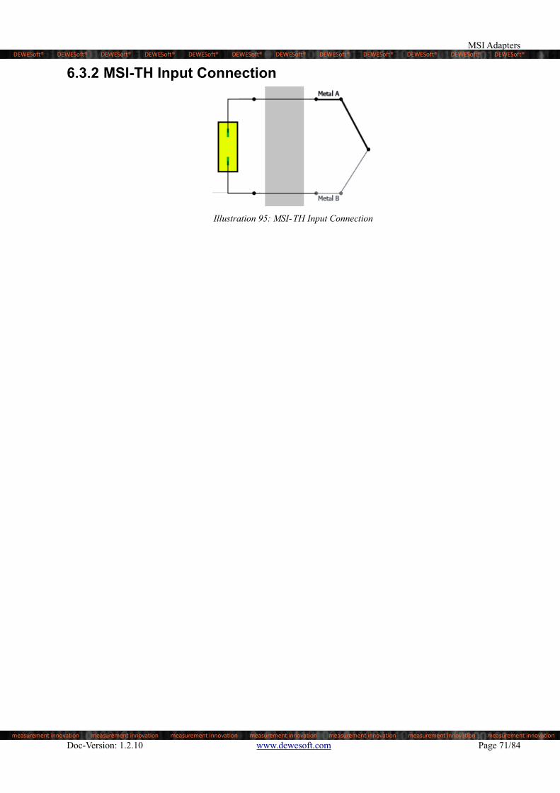
6.3 MSI-TH-xThe MSI-TH-x allows thermocouple temperature measurement with Dewesoft devices. The common thermocouples types K, J and T are supported. For high temperature application also type C is supported. A high precision cold junction compensation is included in the adapter.

The non-linearity of the thermocouple is compensated for in software. A TEDS chip provides automatic adapter identification by software and the calibration data.

In operation with the isolated SIRIUSi modules you will get a fully isolated thermocouple amplifier. In operation with

the differential SIRIUS® modules (or Krypton™/DEWE-43) only isolated thermocouples should be used, because the thermocouple input is single ended.

Illustration 94: Basic circuit design of MSI-TH-x

Doc-Version: 1.2.10 www.dewesoft.com Page 69/84

DEWESoft® DEWESoft® DEWESoft® DEWESoft® DEWESoft® DEWESoft® DEWESoft® DEWESoft® DEWESoft® DEWESoft® DEWESoft® DEWESoft®

measurement innovation measurement innovation measurement innovation measurement innovation measurement innovation measurement innovation measurement innovation

Accessories & Sensors

6.3.1 MSI-TH-x Specifications

Sensor connection

1 m cable with standard miniature thermocouple connector according to TC type

Thermocouple Types

MSI-TH-K: Type KMSI-TH-J: Type JMSI-TH-T: Type TMSI-TH-C: Type C

Cold junction compensation Integrated

CJC accuracy 1.0°C

Input impedance > 10 MΩ

BIAS current 50nA

Open TC detection Yes

Linearisation Through software according to the sensor type

TEDS For adapter identification and calibration data

Table 26: MSI-TH-x Specifications

Host amplifierSIRIUSx-Multi

SIRIUSx-STGM

SIRIUSx-STG

SIRIUSx-STGMv2

SIRIUSx-HD-STGS

SIRIUSx-HS-STG SIRIUSx-HD-LV DEWE-43

Bandwidth 70 kHz 70 kHz 70 kHz 70 kHz 70 kHz

Typical peak to peak noise (Type K)

30 kHz bandwidth 0.44 °C 0.44 °C 0.5 °C 0.44 °C 0.44 °C

100 Hz bandwidth 0.22 °C 0.22 °C 0.25 °C 0.22 °C 0.22 °C

1 Hz bandwidth 0.02 °C 0.02 °C 0.02 °C 0.02 °C 0.02 °C

Accuracy including CJC error

MSI-TH-K for thermocouple type K (DIN EN 60584-1)

Input Range Actual reading Typical accuracy [maximum accuracy]

-200 to 1370 °C

-200 to -100 °C ±7.0 [±12.0] °C ±4.6 [± 9.0] °C ±4.6 [± 9.0] °C ±4.6 [± 9.0] °C ±4.6 [± 9.0] °C

-100 to 0 °C ±2.6 [± 6.6] °C ±2.4 [± 4.6] °C ±2.4 [± 4.6] °C ±2.4 [± 4.6] °C ±2.4 [± 4.6] °C

0 to 500 °C ±2.0 [± 5.5] °C ±1.8 [± 3.5] °C ±1.8 [± 3.5] °C ±1.9 [± 3.5] °C ±1.9 [± 3.5] °C

500 to 1000 °C ±2.1 [± 6.1] °C ±2.1 [± 4.1] °C ±2.1 [± 4.1] °C ±2.5 [± 4.1] °C ±2.5 [± 4.1] °C

1000 to 1370 °C ±3.0 [± 7.0] °C ±2.5 [± 5.0] °C ±2.5 [± 5.0] °C ±3.0 [± 5.0] °C ±3.0 [± 5.0] °C

MSI-TH-j for thermocouple type J (DIN EN 60584-1)

Input Range

-200 to 1370 °C

Actual reading Typical accuracy [maximum accuracy]-200 to -100 °C ±4.0 [± 9.0] °C ±4.0 [± 7.0] °C ±4.0 [± 7.0] °C ±4.0 [± 7.0] °C ±4.0 [± 7.0] °C

-100 to 0 °C ±2.0 [± 5.7] °C ±1.7 [± 3.7] °C ±1.7 [± 3.7] °C ±2.0 [± 3.7] °C ±2.0 [± 3.7] °C

0 to 300 °C ±1.6 [± 5.0] °C ±1.6 [± 3.0] °C ±1.6 [± 3.0] °C ±1.6 [± 3.0] °C ±1.6 [± 3.0] °C

300 to 1000 °C ±2.0 [± 5.2] °C ±1.8 [± 3.2] °C ±1.8 [± 3.2] °C ±2.0 [± 3.2] °C ±2.0 [± 3.2] °C

MSI-TH-T for thermocouple type T (DIN EN 60584-1)

Input Range

-270 to 400 °C

Actual reading Typical accuracy [maximum accuracy]-250 to -100 °C ±7.0 [±25.0] °C ±7.0 [±19.0] °C ±7.0 [±19.0] °C ±7.0 [±19.0] °C ±7.0 [±19.0] °C

-100 to 0 °C ±1.8 [± 7.0] °C ±1.8 [± 5.0] °C ±1.8 [± 5.0] °C ±1.8 [± 5.0] °C ±1.8 [± 5.0] °C

0 to 100 °C ±1.3 [± 5.6] °C ±1.3 [± 3.6] °C ±1.3 [± 3.6] °C ±1.3 [± 3.6] °C ±1.3 [± 3.6] °C

100 to 400 °C ±1.0 [± 5.0] °C ±1.0 [± 3.0] °C ±1.0 [± 3.0] °C ±1.0 [± 3.0] °C ±1.0 [± 3.0] °C

MSI-TH-C for thermocouple type C (ASTM E988-96)

Input Range

-270 to 400 °C

Actual reading Typical accuracy [maximum accuracy] 0 to 1000 °C ±3.0 [±12.0] °C ±3.0 [± 8.0] °C ±3.0 [± 8.0] °C ±3.0 [± 8.0] °C ±3.0 [± 8.0] °C

1000 to 1600 °C ±4.0 [±11.6] °C ±4.0 [± 8.6] °C ±4.0 [± 8.6] °C ±4.0 [± 8.6] °C ±4.0 [± 8.6] °C

1600 to 2300 °C ±6.7 [±19.0] °C ±6.7 [±14.0] °C ±6.7 [±14.0] °C ±6.7 [±14.0] °C ±6.7 [±14.0] °C

Table 27: MSI-TH-x Accuracy

Page 70/84 www.dewesoft.com Doc-Version: 1.2.10

DEWESoft® DEWESoft® DEWESoft® DEWESoft® DEWESoft® DEWESoft® DEWESoft® DEWESoft® DEWESoft® DEWESoft® DEWESoft® DEWESoft®

measurement innovation measurement innovation measurement innovation measurement innovation measurement innovation measurement innovation measurement innovation

MSI Adapters

6.3.2 MSI-TH Input Connection

Illustration 95: MSI-TH Input Connection

Doc-Version: 1.2.10 www.dewesoft.com Page 71/84

DEWESoft® DEWESoft® DEWESoft® DEWESoft® DEWESoft® DEWESoft® DEWESoft® DEWESoft® DEWESoft® DEWESoft® DEWESoft® DEWESoft®

measurement innovation measurement innovation measurement innovation measurement innovation measurement innovation measurement innovation measurement innovation

Accessories & Sensors

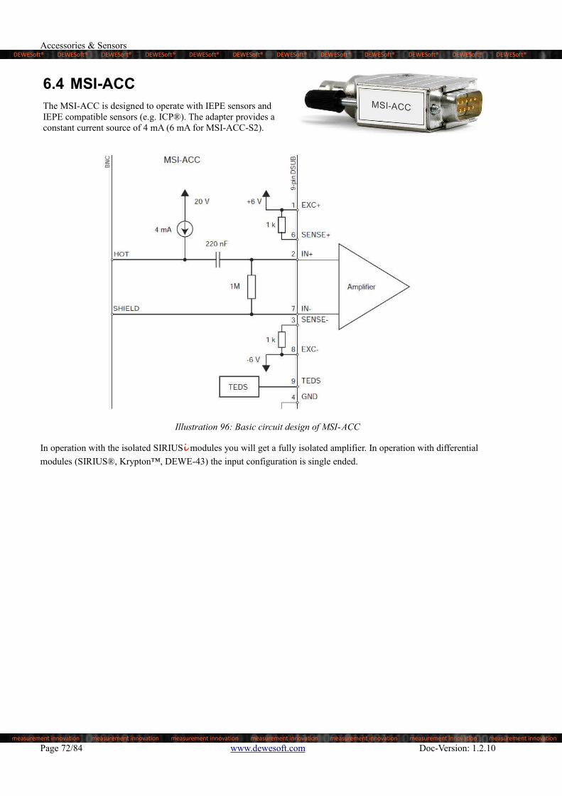
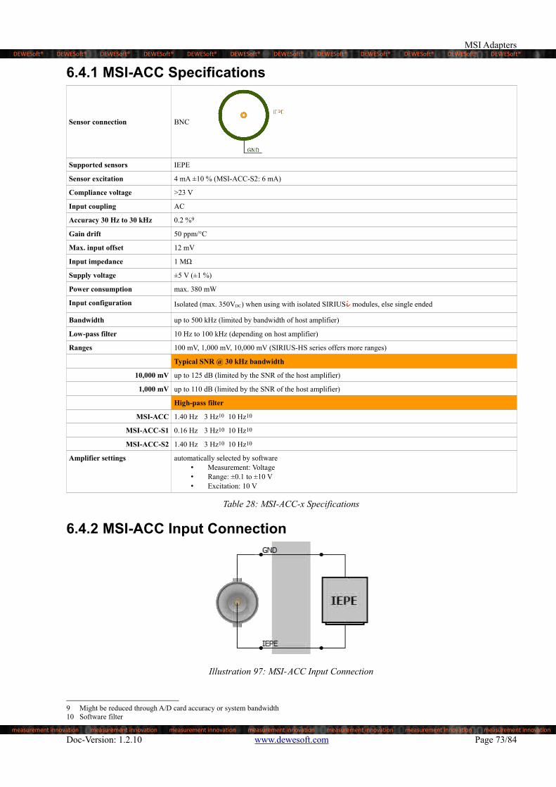
6.4 MSI-ACCThe MSI-ACC is designed to operate with IEPE sensors and IEPE compatible sensors (e.g. ICP®). The adapter provides a constant current source of 4 mA (6 mA for MSI-ACC-S2).

Illustration 96: Basic circuit design of MSI-ACC

In operation with the isolated SIRIUSi modules you will get a fully isolated amplifier. In operation with differential

modules (SIRIUS®, Krypton™, DEWE-43) the input configuration is single ended.

Page 72/84 www.dewesoft.com Doc-Version: 1.2.10

DEWESoft® DEWESoft® DEWESoft® DEWESoft® DEWESoft® DEWESoft® DEWESoft® DEWESoft® DEWESoft® DEWESoft® DEWESoft® DEWESoft®

measurement innovation measurement innovation measurement innovation measurement innovation measurement innovation measurement innovation measurement innovation

MSI Adapters

6.4.1 MSI-ACC Specifications

Sensor connection BNC

Supported sensors IEPE

Sensor excitation 4 mA ±10 % (MSI-ACC-S2: 6 mA)

Compliance voltage >23 V

Input coupling AC

Accuracy 30 Hz to 30 kHz 0.2 %9

Gain drift 50 ppm/°C

Max. input offset 12 mV

Input impedance 1 MΩ

Supply voltage ±5 V (±1 %)

Power consumption max. 380 mW

Input configuration Isolated (max. 350VDC) when using with isolated SIRIUSi modules, else single ended

Bandwidth up to 500 kHz (limited by bandwidth of host amplifier)

Low-pass filter 10 Hz to 100 kHz (depending on host amplifier)

Ranges 100 mV, 1,000 mV, 10,000 mV (SIRIUS-HS series offers more ranges)

Typical SNR @ 30 kHz bandwidth

10,000 mV up to 125 dB (limited by the SNR of the host amplifier)

1,000 mV up to 110 dB (limited by the SNR of the host amplifier)

High-pass filter

MSI-ACC 1.40 Hz 3 Hz10 10 Hz10

MSI-ACC-S1 0.16 Hz 3 Hz10 10 Hz10

MSI-ACC-S2 1.40 Hz 3 Hz10 10 Hz10

Amplifier settings automatically selected by software• Measurement: Voltage• Range: ±0.1 to ±10 V• Excitation: 10 V

Table 28: MSI-ACC-x Specifications

6.4.2 MSI-ACC Input Connection

Illustration 97: MSI-ACC Input Connection

9 Might be reduced through A/D card accuracy or system bandwidth10 Software filter

Doc-Version: 1.2.10 www.dewesoft.com Page 73/84

DEWESoft® DEWESoft® DEWESoft® DEWESoft® DEWESoft® DEWESoft® DEWESoft® DEWESoft® DEWESoft® DEWESoft® DEWESoft® DEWESoft®

measurement innovation measurement innovation measurement innovation measurement innovation measurement innovation measurement innovation measurement innovation

Accessories & Sensors

6.5 MSI-CHG-xThere are several variants of the MSI-CHG adapter:

MSI-CHG-50 for charge sensors up to 50,000 pC

MSI-CHG-100 for charge sensors up to 100,000 pC

Illustration 98: Basic circuit design of MSI-CHG

In operation with the isolated SIRIUSi modules you will get a fully isolated charge amplifier. In operation with

differential modules (SIRIUS®, Krypton™, DEWE-43) the input configuration is single ended.

Page 74/84 www.dewesoft.com Doc-Version: 1.2.10

DEWESoft® DEWESoft® DEWESoft® DEWESoft® DEWESoft® DEWESoft® DEWESoft® DEWESoft® DEWESoft® DEWESoft® DEWESoft® DEWESoft®

measurement innovation measurement innovation measurement innovation measurement innovation measurement innovation measurement innovation measurement innovation

MSI Adapters

6.5.1 MSI-CHG-x Specifications

Sensor connection BNC

Supported sensors Charge sensors

Accuracy 0.5%

Gain drift 100 ppm/°C

Supply voltage ±5 V (±1 %)

Power consumption max. 100 mW

Input configuration Isolated (max. 350VDC) when using with isolated SIRIUSi modules, else differential

Bandwidth 0.08 Hz up to 100 kHz (limited by bandwidth of host amplifier)

Low-pass filter 10 Hz to 100 kHz (depending on host amplifier)

Ranges

MSI-CHG-50 1,000/10,000/50,000 pC (SIRIUS-HS series offers more ranges)

MSI-CHG-100 2,000/20,000/100,000 pC (SIRIUS-HS series offers more ranges)

Typical SNR @ 30 kHz bandwidth

50,000 pC up to 125 dB (limited by the SNR of the host amplifier)

10,000 pC up to 110 dB (limited by the SNR of the host amplifier)

Max. offset

MSI-CHG-50 20 pC

MSI-CHG-100 40 pC

High-pass filter 0.08 Hz 1 Hz11 10 Hz11

Amplifier settings automatically selected by software• Measurement: Voltage• Range: ±0.1 to ±10 V• Excitation: 10 V

Table 29: MSI-CHG Specifications

6.5.2 MSI-CHG Input Connection

Illustration 99: MSI-CHG Input Connection

11 Software filter

Doc-Version: 1.2.10 www.dewesoft.com Page 75/84

DEWESoft® DEWESoft® DEWESoft® DEWESoft® DEWESoft® DEWESoft® DEWESoft® DEWESoft® DEWESoft® DEWESoft® DEWESoft® DEWESoft®

measurement innovation measurement innovation measurement innovation measurement innovation measurement innovation measurement innovation measurement innovation

Accessories & Sensors

6.6 MSI-V-200Basically the adapter consist of an active voltage divider (50:1), which allows an input range up to ±200 V. The picture below shows the basic configuration of the amplifier circuit:

Illustration 100: Basic circuit design of MSI-V-200

In operation with the isolated SIRIUSi modules you will get a fully isolated amplifier. In operation with differential

modules (SIRIUS®, Krypton™, DEWE-43) the input configuration is differential.

Page 76/84 www.dewesoft.com Doc-Version: 1.2.10

DEWESoft® DEWESoft® DEWESoft® DEWESoft® DEWESoft® DEWESoft® DEWESoft® DEWESoft® DEWESoft® DEWESoft® DEWESoft® DEWESoft®

measurement innovation measurement innovation measurement innovation measurement innovation measurement innovation measurement innovation measurement innovation

MSI Adapters

6.6.1 MSI-V-200 Specifications

Sensor connection BNC

Ranges ±200 V, ±40 V, ±4 V (SIRIUS-HS series offers more ranges)

±4 V to ±150 V ±150 V to ±200 V

DC Accuracy ±0.07 % of reading ±0.04 % of range ± 10mV ±1 % of reading ±0.04 % of range

Bandwidth (-3dB) 200 kHz (limited by bandwidth of host amplifier)

Low-pass filter 10 Hz to 100 kHz (depending on host amplifier)

Common mode voltage range ± 200 V

Input overvoltage protection ± 250 V

Input impedance In+ 1 MΩ

Input impedance In- 1 MΩ

Gain drift typ. 15 ppm/K (max. 30 ppm/K)

Input offset drift: typl 10 µV/K (max. 25 µV/K)

Input attenuation 50 ±0.5 % (uncalibrated)

Input configuration Isolated (max. 350VDC) when using with isolated SIRIUSi modules, else differential

Typical SNR @ 30 kHz BW 98 dB @ 200 V range98 dB @ 40 V range79 dB @ 4 V range

Host: Isolated amplifier 160 dB DC, 110 dB @ 1 kHz

Host: Differential amplifier 100 dB @ 100 Hz, 60 dB @ 10 kHz

Amplifier settings automatically selected by software• Measurement: Voltage• Range: ±0.1 to ±10 V• Excitation: 10 V

Table 30: MSI-V-200 Specifications

WARNINGFor safety reasons max. 50 V may be applied to the BNC input-connectors!Refer to the regulation of maximum allowable touch potential.

6.6.2 MSI-V-200 Input Connection

Illustration 101: MSI-V-200 Input Connection

Doc-Version: 1.2.10 www.dewesoft.com Page 77/84

DEWESoft® DEWESoft® DEWESoft® DEWESoft® DEWESoft® DEWESoft® DEWESoft® DEWESoft® DEWESoft® DEWESoft® DEWESoft® DEWESoft®

measurement innovation measurement innovation measurement innovation measurement innovation measurement innovation measurement innovation measurement innovation

Accessories & Sensors

6.7 MSI-RTDThe MSI-RTD allows temperature and resistor measurement based on a precise 1.25 mA constant current source. All common RTD types (Pt100, Pt200, Pt500, Pt1000, Pt2000) are supported.

When a 3-wire connection is used, an amplifier compensates the lead resistance completely if all three wires have the same diameter and length. The non linearity of the RTD is compensated by the software.

The picture below shows the principal MSI-RTD circuit:

Illustration 102: Basic circuit design of MSI-RTD

6.7.1 MSI-RTD Specifications

Sensor connection 5-pin BINDER connector series 712

Supported sensors Resistance: Pt100; Pt200; Pt500; Pt1000; Pt2000

Temperature range -200 °C to 850 °C

Input offset 50 µV

Constant current 1.25 mA

Constant current accuracy ±0.02 % from calibrated value

Constant current drift 22 ppm/ °C

Linearisation Through software according to sensor type

Connection types 2-, 3- or 4-wire

Bandwidth (-3dB) 10 kHz (limited by bandwidth of host amplifier)

Input configuration Isolated (max. 350VDC) when using with isolated SIRIUSi modules, else differential

Typ. noise: 100 Hz bandwidth 0.03 °C

Amplifier settings automatically selected by software• Measurement: Voltage• Range: ±0.1 to ±10 V• Excitation: 10 V

Table 31: MSI-RTD Specifications

Page 78/84 www.dewesoft.com Doc-Version: 1.2.10

DEWESoft® DEWESoft® DEWESoft® DEWESoft® DEWESoft® DEWESoft® DEWESoft® DEWESoft® DEWESoft® DEWESoft® DEWESoft® DEWESoft®

measurement innovation measurement innovation measurement innovation measurement innovation measurement innovation measurement innovation measurement innovation

MSI Adapters

Measurement Hardware

Sirius or Siriusi LVv2 / STGv2 / HS-LV / HS-STG STGMv2 / HD-LV / HD-STG Multi / STGM

Krypton STG

Other DEWE-43 / Minitaur

Resistance Range

80 Ω ±0.05 % of reading ±120 mΩ ±0.05 % of reading ±120 mΩ ±0.05 % of reading ±200 mΩ

800 Ω ±0.05 % of reading ±200 mΩ ±0.05 % of reading ±200 mΩ ±0.05 % of reading ±840 mΩ

6 kΩ ±0.05 % of reading ±840 mΩ ±0.05 % of reading ±1500 mΩ ±0.05 % of reading ±8 Ω

DIN Sensor Range Temperature

EN 60751 Pt100 -200 to 850°C ±0.1 % of reading ±0.69 °C ±0.1 % of reading ±0.69 °C ±0.1 % of reading ±2.5 °C

EN 60751 Pt200 -200 to 850°C ±0.1 % of reading ±0.44 °C ±0.1 % of reading ±0.44 °C ±0.1 % of reading ±1.2 °C

EN 60751 Pt500-200 to 850°C ±0.1 % of reading ±0.61 °C ±0.1 % of reading ±1 °C ±0.1 % of reading ±4 °C

-200 to 150°C ±0.1 % of reading ±0.28 °C ±0.1 % of reading ±0.28 °C ±0.1 % of reading ±1.2 °C

EN 60751 Pt1000 -200 to 850°C ±0.1 % of reading ±0.39 °C ±0.1 % of reading ±0.8 °C ±0.1 % of reading ±3 °C

EN 60751 Pt2000 -200 to 550°C ±0.1 % of reading ±0.29 °C ±0.1 % of reading ±0.5 °C ±0.1 % of reading ±1.5 °C

Table 32: MSI-RTD Accuracy

6.7.2 MSI-RTD Input Connection

Illustration 103: MSI-RTD Input Connection

Doc-Version: 1.2.10 www.dewesoft.com Page 79/84

DEWESoft® DEWESoft® DEWESoft® DEWESoft® DEWESoft® DEWESoft® DEWESoft® DEWESoft® DEWESoft® DEWESoft® DEWESoft® DEWESoft®

measurement innovation measurement innovation measurement innovation measurement innovation measurement innovation measurement innovation measurement innovation

Appendix

7 Appendix

7.1 Glossary and abbreviationsThis glossary includes explanations of some of the most important terms and abbreviations that are used in documentation.

CJC

Cold junction compensation.

Thermocouples measure the temperature difference between two points, not absolute temperature. To measure a single temperature one of the junctions - normally the cold junction - is maintained at a known reference temperature, and the other junction is at the temperature to be sensed.

Having a junction of known temperature, while useful for laboratory calibration, is not convenient for most measurement and control applications. Instead, they incorporate an artificial cold junction using a thermally sensitive device such as a thermistor or diode to measure the temperature of the input connections at the instrument, with special care being taken to minimize any temperature gradient between terminals. Hence, the voltage from a known cold junction can be simulated, and the appropriate correction applied. This is known as cold junction compensation.

dB

The decibel (dB) is a logarithmic unit that indicates the ratio of a physical quantity (usually power or intensity) relative to a specified or implied reference level. A ratio in decibels is ten times the logarithm to base 10 of the ratio of two power quantities.

Dewesoft

Dewesoft refers to the company.

DEWESoft® refers to the software suite for data acquisition, data processing, data analysis and much more.

see www.dewesoft.com

DSI®

The versatile Dewesoft Smart Interface adapters make it possible to connect virtually any sensor to the DSUB9 analogue input of your Dewesoft instrument and read both the TEDS information from the adapter and from the connected sensor..For example: use a DSI-ACC adapter to connect an IEPE/ICP input to your DEWE-43.Since the adapter includes a TEDS sensor, DEWESoft® X can read all the sensor configuration automatically

Dynamic Range

Dynamic Range is the ratio of a specified full scale input range to the to the minimum detectable value (peak spurious signal). The value for dynamic range is expressed in decibels (dB).

FFT

Fast Fourier transformation (FFT) can be used to show the frequency components of the acquired signals in amplitude and frequency. DEWESoft® has a built-in visual control that makes FFT easy to use.

Doc-Version: 1.2.10 www.dewesoft.com Page 81/84

DEWESoft® DEWESoft® DEWESoft® DEWESoft® DEWESoft® DEWESoft® DEWESoft® DEWESoft® DEWESoft® DEWESoft® DEWESoft® DEWESoft®

measurement innovation measurement innovation measurement innovation measurement innovation measurement innovation measurement innovation measurement innovation

Accessories & Sensors

GND

the electrical ground (aka. earth)

Hz

The hertz (symbol: Hz) is the SI unit of frequency defined as the number of cycles per second of a periodic signal.

ICP®

Integrated Circuit-Piezoelectric, or ICP®, is a trademark of PCB Piezotronics, Inc. and refers specifically to the IEPE devices that they manufacturer.

IEPE

Integrated Electronic Piezoelectric refers to a type of transducer that is packaged with a built-in charge amplifier or voltage amplifier.

see also ICP®

LED

A light-emitting diode is a semiconductor light source.

MSI

The versatile Modular Smart Interface adapters make it possible to connect virtually any sensor to the DSUB9 analogueinput of your Dewesoft instrument.For example: use an MSI-ACC adapter to connect an IEPE/ICP input to your DEWE-43.Since the adapter includes a TEDS sensor, DEWESoft® X can read all the sensor configuration automatically

PC

Sirius® systems are typically connected to a Personal Computer which runs DEWESoft® to fetch the measurement data.

See also: Host System

RFI

Electromagnetic interference (EMI) is called Radio-frequency interference, when it is in the radio frequency spectrum. RFI is a disturbance generated by an external source that affects an electrical circuit by electromagnetic induction, electrostatic coupling, or conduction.

RMS

Root Mean Square, also known as the quadratic mean, is a statistical measure of the magnitude of a varying quantity. It is especially useful when variates are positive and negative, e.g., sinusoids. RMS is used in various fields, including electrical engineering.

Page 82/84 www.dewesoft.com Doc-Version: 1.2.10

DEWESoft® DEWESoft® DEWESoft® DEWESoft® DEWESoft® DEWESoft® DEWESoft® DEWESoft® DEWESoft® DEWESoft® DEWESoft® DEWESoft®

measurement innovation measurement innovation measurement innovation measurement innovation measurement innovation measurement innovation measurement innovation

Appendix

RTD

Resistance thermometers, also called resistance temperature detectors or resistive thermal devices (RTDs), are temperature sensors that exploit the predictable change in electrical resistance of some materials with changing temperature; e.g. Pt100 and Pt1000

SNR

Signal to Noise Ratio is the ratio of the RMS value of the full scale input range to the total RMS noise measured with the inputs shorted together. The value for SNR is expressed in decibels (dB).

TEDS

A Transducer Electronic Datasheet (TEDS) is a standardized method of storing transducer (sensors or actuators) identification, calibration, correction data, and manufacturer-related information. DEWESoft® X uses the manufacturer related information to store DEWESoft® specific amplifier settings and configuration directly to the TEDS-chip: Thus, you just need to connect the sensor to the measurement device and, everything is set up and you can start the measurement immediately!

Doc-Version: 1.2.10 www.dewesoft.com Page 83/84

DEWESoft® DEWESoft® DEWESoft® DEWESoft® DEWESoft® DEWESoft® DEWESoft® DEWESoft® DEWESoft® DEWESoft® DEWESoft® DEWESoft®

measurement innovation measurement innovation measurement innovation measurement innovation measurement innovation measurement innovation measurement innovation

Accessories & Sensors

7.2 Documentation version historyRevision number: 278Last modified: Mon 02 Dec 2019, 10:03

VersionDate

[dd.mm.yyyy] Notes

1.0.0 01.12.2015 ☑ Initial revision

1.0.1 02.12.2015 ☑ Corrected SNR ranges of MSI-ACC

1.1.0 02.03.2016 ☑ Added chapter for Sensors

1.2.0 12.05.2016 ☑ Added DSI® adapters: TH-x, ACC, CHG-50, V-200, RTD, 20mA☑ Added MSI-V-200☑ Added MSI-RTD☑ Updated Battery Packs☑ Updated Accuracy of DS-CLAMP-150DC and DS-CLAMP-150DCS☑ Updated Specs of PWR-MCTS2

1.2.1 12.05.2016 ☑ Corrected Sensor excitation of DSI-ACC-20mA

1.2.2 27.05.2016 ☑ Added DS-SHUNT-05☑ Zero-Flux Transducers: corrected Output Ratio of IT 700-S☑ Added DSIi-10A

1.2.3 12.05.17 ☑ DS-SHUNT-05: added Phase Error and Bandwidth☑ AC CLAMPS: updated Current Ranges☑ removed “Overload Capability” from Table 15: DC CLAMP: Characteristics☑ updated “Table 18: DSIi-10A Specifications”☑ Added MSI-5A☑ Updated Zero-Flux-Transducers: added / updated specifications, dimensions

(graphically), over current protection☑ Added SHUNT-DSI-MCTS-X00-03M: Table, Amplitude and Phase Chart☑ Updated DS-CLAMPS: Splitting table in two parts: Flux-Gate and Hall effect☑ @ Flux-Gate: New table, frequency derating curves, measurement procedure, updated

pictures for DS-CLAMP 200DC, 500DCS and 500DC☑ @ Hall effect: Updated Specification table☑ Updated FLEX: Table updated (new coils), pictures updated, text updated

1.2.4 29.06.17 ☑ DSI-ACC Accuracy update from 0.2;0.05;0.2% to 0.3:0.07;0.3%

1.2.5 13.12.17 ☑ Added DS-TACHO2 and DS-TACHO3

1.2.6 04.04.18 ☑ AC CLAMPS, DS-CLAMP-15AC Accuracy and Phase Error update

1.2.7 07.05.18 ☑ DS-CLAMP-150DC & DS-CLAMP-150DCS specifications update

1.2.8 25.01.18 ☑ DS-CLAMP-1000DC, IN 1000-S and IN 2000-S added☑ DS-FLEX-300-17-HS added

1.2.9 29.04.19 ☑ DS-CLAMP-200AC specification update

1.2.10 29.11.19 ☑ DS-Flex-3000-17 specification update☑ DS-Flex-3000-35-HS specification update

Page 84/84 www.dewesoft.com Doc-Version: 1.2.10

DEWESoft® DEWESoft® DEWESoft® DEWESoft® DEWESoft® DEWESoft® DEWESoft® DEWESoft® DEWESoft® DEWESoft® DEWESoft® DEWESoft®

measurement innovation measurement innovation measurement innovation measurement innovation measurement innovation measurement innovation measurement innovation


Recommended