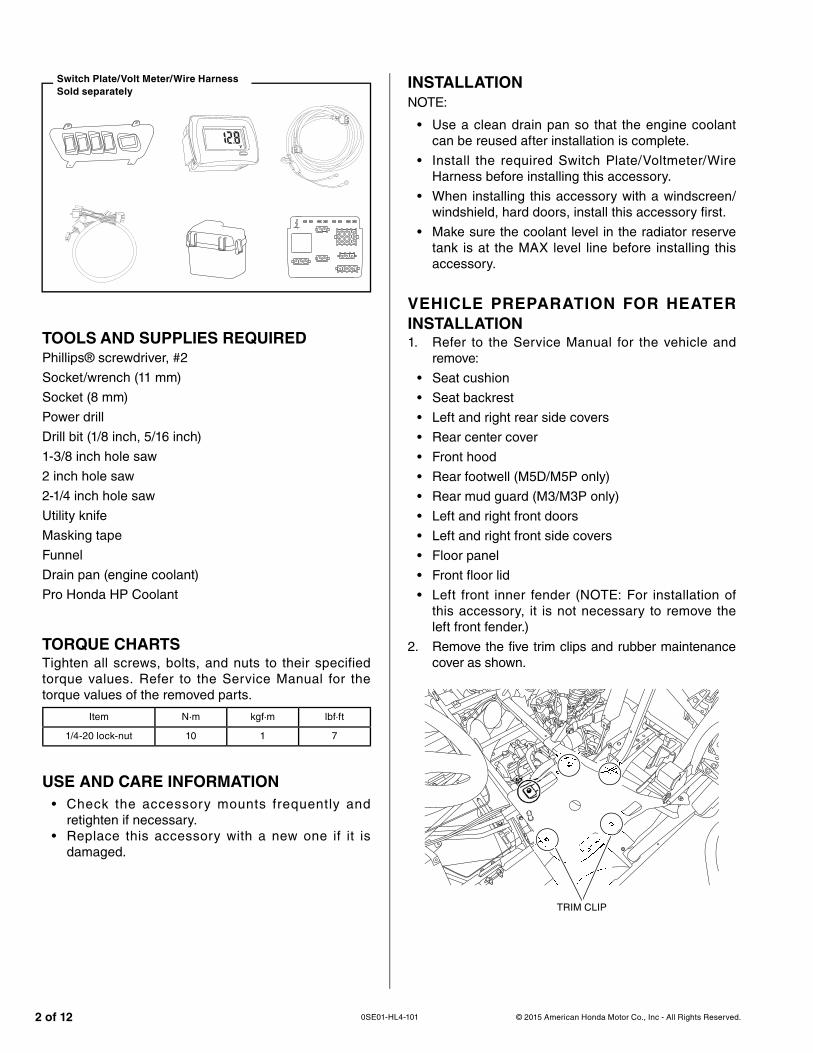
TORQUE CHARTSTighten all screws, bolts, and nuts to their specified torque values. Refer to the Service Manual for the torque values of the removed parts.
Item N·m kgf·m lbf·ft
1/4-20 lock-nut 10 1 7
USE AND CARE INFORMATION
• Check the accessory mounts frequently and retighten if necessary.
• Replace this accessory with a new one if it is damaged.
INSTALLATION
NOTE:
• Use a clean drain pan so that the engine coolant can be reused after installation is complete.
• Install the required Switch Plate/Voltmeter/Wire Harness before installing this accessory.
• When installing this accessory with a windscreen/windshield, hard doors, install this accessory first.
• Make sure the coolant level in the radiator reserve tank is at the MAX level line before installing this accessory.
VEHICLE PREPARATION FOR HEATER
INSTALLATION1. Refer to the Service Manual for the vehicle and
remove:
• Seat cushion
• Seat backrest
• Left and right rear side covers
• Rear center cover
• Front hood
• Rear footwell (M5D/M5P only)
• Rear mud guard (M3/M3P only)
• Left and right front doors
• Left and right front side covers
• Floor panel
• Front floor lid
• Left front inner fender (NOTE: For installation of this accessory, it is not necessary to remove the left front fender.)
2. Remove the five trim clips and rubber maintenance cover as shown.
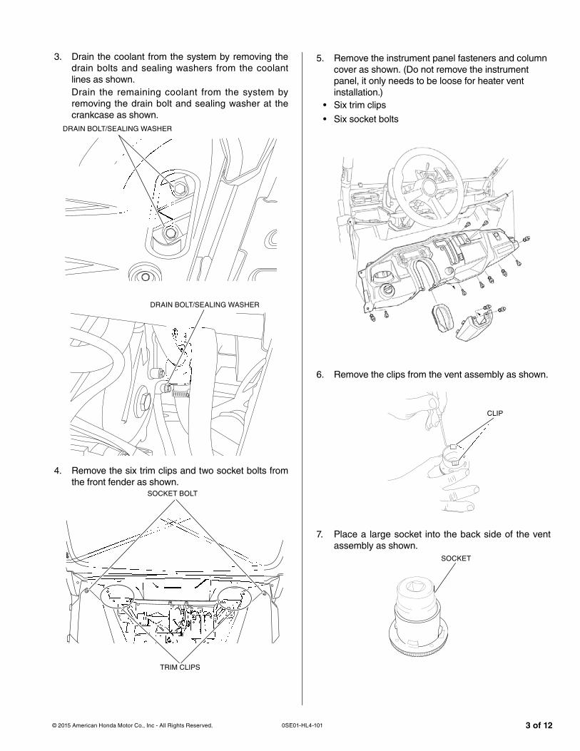
3. Drain the coolant from the system by removing the drain bolts and sealing washers from the coolant lines as shown.Drain the remaining coolant from the system by removing the drain bolt and sealing washer at the crankcase as shown.
DRAIN BOLT/SEALING WASHER
DRAIN BOLT/SEALING WASHER
4. Remove the six trim clips and two socket bolts from the front fender as shown.
TRIM CLIPS
SOCKET BOLT
5. Remove the instrument panel fasteners and column cover as shown. (Do not remove the instrument panel, it only needs to be loose for heater vent installation.)
• Six trim clips
• Six socket bolts
6. Remove the clips from the vent assembly as shown.
CLIP
7. Place a large socket into the back side of the ventassembly as shown.
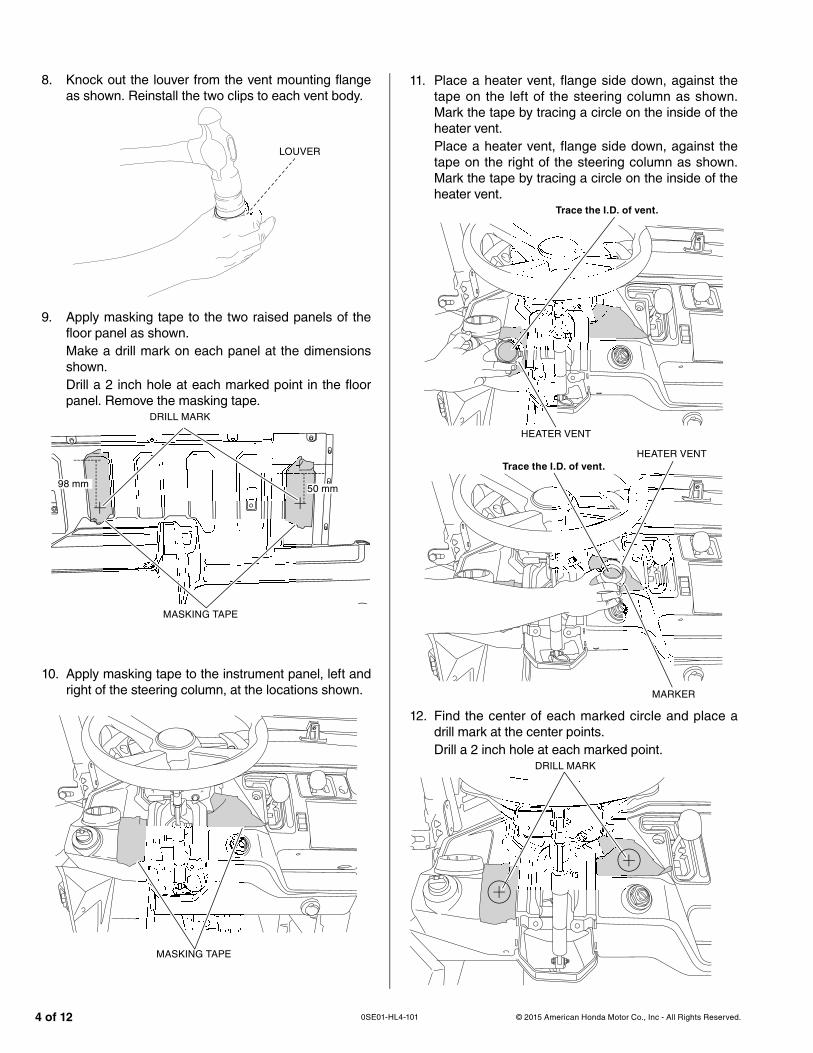
8. Knock out the louver from the vent mounting flangeas shown. Reinstall the two clips to each vent body.
LOUVER
9. Apply masking tape to the two raised panels of the floor panel as shown.Make a drill mark on each panel at the dimensions shown.Drill a 2 inch hole at each marked point in the floor panel. Remove the masking tape.
DRILL MARK
MASKING TAPE
10. Apply masking tape to the instrument panel, left and right of the steering column, at the locations shown.
MASKING TAPE
11. Place a heater vent, flange side down, against the tape on the left of the steering column as shown. Mark the tape by tracing a circle on the inside of the heater vent.Place a heater vent, flange side down, against the tape on the right of the steering column as shown. Mark the tape by tracing a circle on the inside of the heater vent.
HEATER VENT
Trace the I.D. of vent.
HEATER VENT
MARKER
12. Find the center of each marked circle and place a drill mark at the center points.Drill a 2 inch hole at each marked point.
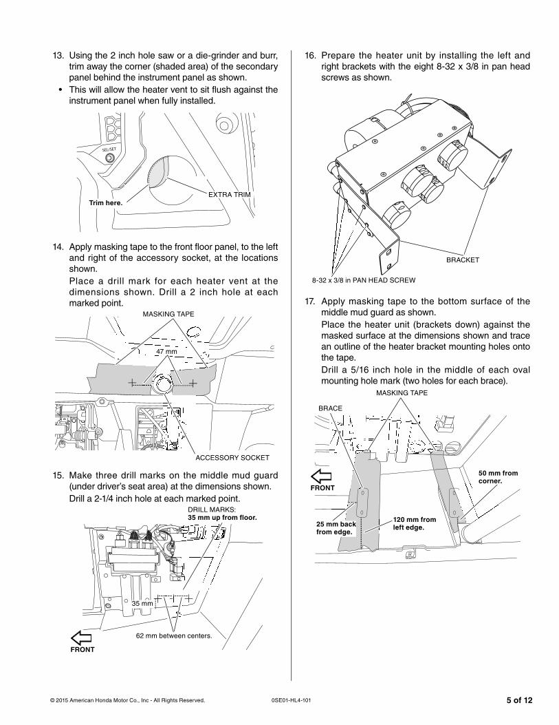
13. Using the 2 inch hole saw or a die-grinder and burr, trim away the corner (shaded area) of the secondary panel behind the instrument panel as shown.
• This will allow the heater vent to sit flush against the instrument panel when fully installed.
EXTRA TRIMTrim here.
14. Apply masking tape to the front floor panel, to the left and right of the accessory socket, at the locations shown.Place a drill mark for each heater vent at the dimensions shown. Drill a 2 inch hole at each marked point.
MASKING TAPE
ACCESSORY SOCKET
15. Make three drill marks on the middle mud guard (under driver’s seat area) at the dimensions shown.Drill a 2-1/4 inch hole at each marked point.
DRILL MARKS:35 mm up from floor.
16. Prepare the heater unit by installing the left and right brackets with the eight 8-32 x 3/8 in pan head screws as shown.
BRACKET
8-32 x 3/8 in PAN HEAD SCREW
17. Apply masking tape to the bottom surface of the middle mud guard as shown.Place the heater unit (brackets down) against the masked surface at the dimensions shown and trace an outline of the heater bracket mounting holes onto the tape.Drill a 5/16 inch hole in the middle of each oval mounting hole mark (two holes for each brace).
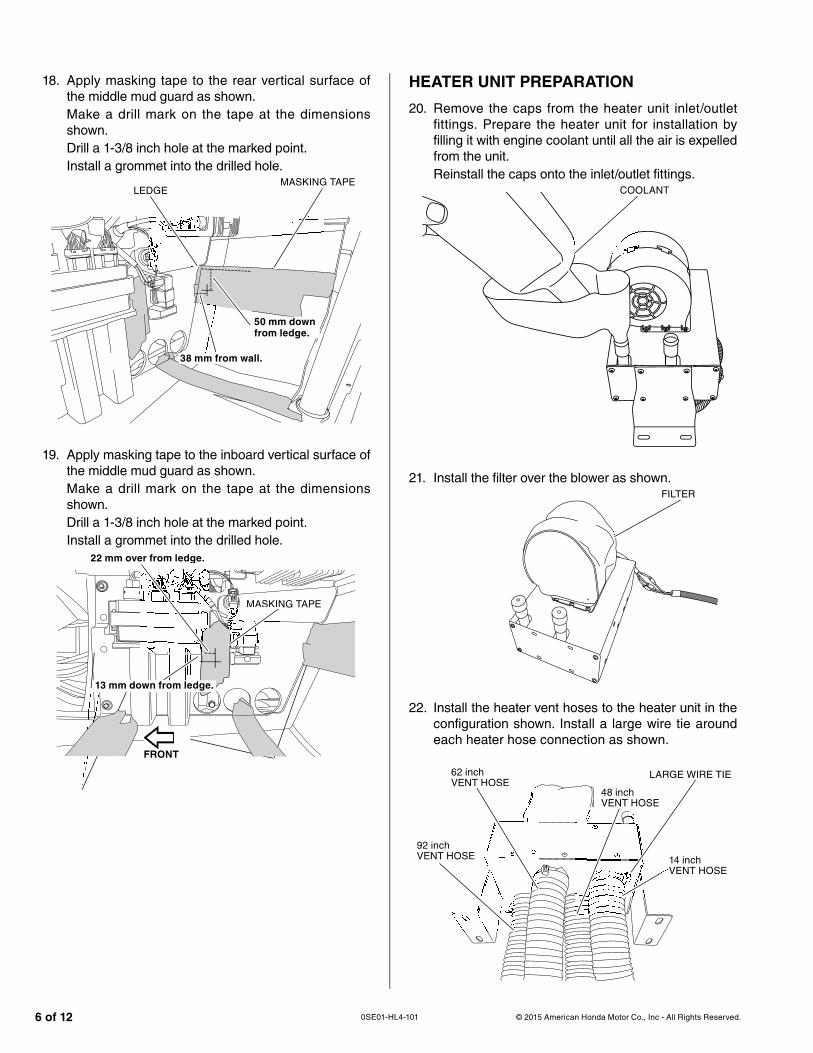
20. Remove the caps from the heater unit inlet/outlet fittings. Prepare the heater unit for installation by filling it with engine coolant until all the air is expelled from the unit. Reinstall the caps onto the inlet/outlet fittings.
COOLANT
21. Install the filter over the blower as shown.FILTER
22. Install the heater vent hoses to the heater unit in the configuration shown. Install a large wire tie around each heater hose connection as shown.
LARGE WIRE TIE
14 inch VENT HOSE
48 inch VENT HOSE
62 inch VENT HOSE
92 inch VENT HOSE
18. Apply masking tape to the rear vertical surface of the middle mud guard as shown. Make a drill mark on the tape at the dimensions shown.Drill a 1-3/8 inch hole at the marked point.Install a grommet into the drilled hole.
MASKING TAPE
38 mm from wall.
50 mm down
from ledge.
LEDGE
19. Apply masking tape to the inboard vertical surface of the middle mud guard as shown.Make a drill mark on the tape at the dimensions shown.Drill a 1-3/8 inch hole at the marked point.Install a grommet into the drilled hole.
23. Install the heater unit to the bottom surface of the middle mud guard with the mounting straps, 1/4-20 x 3/4 inch bolts, 1/4 inch fender washers, and 1/4-20 lock nuts as shown.
• Install the mounting straps underneath the middle mud guard with the bolts going up.
Pull the three longest vent hoses through the three holes in the center mudguard.
LOCK NUTUT
MOUNTING STRAP, BOLT, FENDER WASHER
24. Remove the coolant hose that runs between the oil cooler and the water pump.Save the two plastic clamps as spares, they will not be used for this installation.
OIL COOLER
WATER PUMP
COOLANT HOSE
25. Remove the factory installed hose sheath, then cut the removed coolant hose at the indicated point as shown.
Cut here.146 mm from elbow.frfrff om
26. Install the grommet to the hose stay as shown.• Twist the wire hose stay to the angle shown.
GROMMET
HOSE STAY
27. Install the short side of the cut hose to the oil cooler and route it through the hose stay/grommet as shown.Secure the hose to the oil cooler with the original equipment hose clamp.
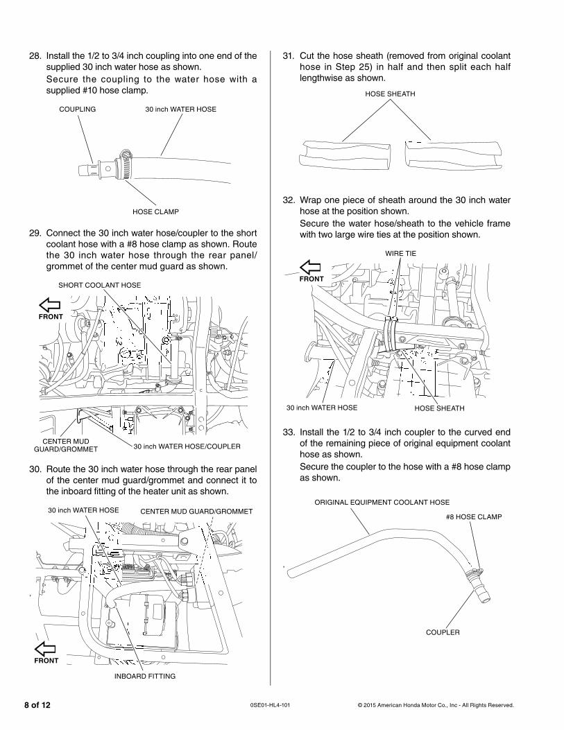
28. Install the 1/2 to 3/4 inch coupling into one end of the supplied 30 inch water hose as shown.Secure the coupling to the water hose with a supplied #10 hose clamp.
COUPLING 30 inch WATER HOSE
HOSE CLAMP
29. Connect the 30 inch water hose/coupler to the short coolant hose with a #8 hose clamp as shown. Route the 30 inch water hose through the rear panel/grommet of the center mud guard as shown.
SHORT COOLANT HOSE
30 inch WATER HOSE/COUPLERCENTER MUD
GUARD/GROMMET
30. Route the 30 inch water hose through the rear panel of the center mud guard/grommet and connect it to the inboard fitting of the heater unit as shown.
,
30 inch WATER HOSE
INBOARD FITTING
CENTER MUD GUARD/GROMMET
31. Cut the hose sheath (removed from original coolant hose in Step 25) in half and then split each half lengthwise as shown.
HOSE SHEATH
32. Wrap one piece of sheath around the 30 inch water hose at the position shown.Secure the water hose/sheath to the vehicle frame with two large wire ties at the position shown.
30 inch WATER HOSE
WIRE TIE
HOSE SHEATH
33. Install the 1/2 to 3/4 inch coupler to the curved end of the remaining piece of original equipment coolant hose as shown.Secure the coupler to the hose with a #8 hose clamp as shown.
34. Route the assembled coolant hose/coupler through the inboard panel of the center mud guard as shown.Connect the coolant hose to the water pump with the original equipment hose clamp.
HOSE CLAMP COOLANT HOSE/COUPLER
WATER PUMP
35. Connect the supplied 10 inch water hose to the coupler, then the outboard fitting of the heater unit as shown.Secure each end of the water hose with a #10 hose clamp.
COUPLERCOUPPPPP#10 HOSE CLAMP
OUTBOARD FITTING 10 inch WATER HOSE
36. Secure the outboard water hose to the bottom of the seat frame with the remaining piece of sheath and two large wire ties as shown.
SEAT FRAME WIRE TIE
SHEATH
37. Refer to page 9-5 of the Service Manual and follow the coolant filling and bleeding procedure.
• Make sure the coolant level in the coolant reserve tank is at the MAX level line.
ELECTRICAL CONNECTIONS
38. Route the heater unit wire harness through the center mud guard into the engine compartment as shown.Connect the black ground wire to the main vehicle ground bolt as shown.
39. Route the heater unit wire harness alongside the control cables and up into the under hood compartment as shown.
,
WIRE HARNESS
CONTROL CABLES
40. Refer to the Installation Instructions for the Switchplate/Voltmeter/Wire Harness, install the supplied heater switch into the switchplate.Connect the heater unit wire harness to the heater switch and power circuit board.
HEATER SWITCH
POWER CIRCUIT BOARD
HEATER VENT INSTALLATION
41. Install a vent mounting flange to each 2 inch hole with four #6 x 5/8 inch tapping screws as shown.
#6 x 5/8 inch TAPPING SCREW
42. Install a louver into each vent mounting flange as shown.
43. Route the heater hoses, install the air wyes, and connect hoses to vents as shown:• Install an air wye to the end of the 92 inch and 62 inch vent hoses.
• Install the 16 inch and 19 vent hoses to the air wye of the 92 inch vent hose.
• Install the two 13 inch vent hoses to the air wye of the 62 inch vent hose.
• Secure each hose end to the air wye with a large wire tie.
• Connect the 19 inch and 16 inch vent hoses to the vents are either side of the steering wheel as shown.
• Connect the 13 inch hoses to the vents on either side of the accessory socket as shown.
• Secure each hose end to the vent with a large wire tie.
44. Refer to the Service Manual, then reinstall the floor panel.Connect the under-seat vent hoses to the vents in the floor panel.Secure each hose end to the vent with a large wire tie.
45. The heater installation is complete. Refer to the Service Manual, then reinstall the removed parts in the reverse order of removal.
46. Test drive the vehicle and check the heater performance.Check for leaks and correct as necessary.
• Make sure the coolant level in the reserve tank is at the MAX level.
• Coolant will be consumed from the reserve tank as air is expelled from the cooling system during and after test drives.