Aircraft Type and Registration: Piper PA-28-161 Cadet, G-TLET
No & Type of Engines: 1 Thielert TAE 125-02-99 diesel engine
Year of Manufacture: 1989 (Serial no: 2841259)
Date & Time (UTC): 21 July 2012 at 1458 hrs
Location: Field south of Shoreham Airport, West Sussex
Type of Flight: Training
Persons on Board: Crew - 2 Passengers - None
Injuries: Crew - None Passengers - N/A
Nature of Damage: Damage to propeller, landing gear, and wing spar
Commander’s Licence: Airline Transport Pilot’s Licence
Commander’s Age: 26 years
Commander’s Flying Experience: 840 hours (of which 642 were on type) Last 90 days - 158 hours Last 28 days - 47 hours
Information Source: Aircraft Accident Report Form submitted by the pilot and further enquiries by the AAIB
Synopsis
At about 200 ft aal after takeoff the engine suffered a sudden loss of power and the pilot initiated a forced landing. The aircraft touched down in a field at the end of the runway but then it hit a fence, a hedge and a large mound, which caused significant damage to the aircraft. The loss of power was caused by failure of a clamp between the turbocharger compressor outlet and the turbo pipe assembly. This clamp had failed due to a fatigue crack that had initiated at multiple sites on the inner diameter and then propagated through the thickness of the sidewall. Following the accident the maintenance organisation discovered another cracked clamp, which had not yet failed, on another aircraft fitted with the same engine type. Three Safety Recommendations are made.
History of the flight
The instructor pilot was carrying out circuit training with a student and they had successfully completed two ‘touch-and-go’ departures from Runway 20. During the climb-out from the third touch-and-go, at about 200 ft aal, there was a sudden and significant loss of engine power and the aircraft began to sink. The instructor exercised the throttle lever and, with no response from the engine, decided to land in the nearest safe area and made a MAYDAY call. The aircraft touched down in a field to the south of the runway and the railway track, just outside the airport perimeter, then hit a hedge and fence and continued over a large mound of earth that ran along the length of the field. The impact with the mound caused the landing gear to collapse and all three wheels
to separate from the aircraft. The instructor followed the shut-down procedures to secure the aircraft and exited, with the student, through the main door.
Engine recorded data
The aircraft was fitted with a Thielert TAE 125-02-99 turbo-charged diesel engine, also known as the Centurion 2.0. This engine has a Full Authority Digital Engine Control (FADEC) unit which records some engine parameters. A download of this data revealed that shortly after takeoff the propeller rpm reduced from 2,300 rpm to 1,940 rpm and the manifold pressure reduced from 2,024 mb to 1,010 mb, representing a 50% loss of power, while the throttle lever remained at 100%. The throttle lever was subsequently reduced from 100% to 60% and returned to 100% with no effect on the engine power.
Engine examination
The aircraft was recovered by a maintenance organisation and examination of the engine revealed that there was a clamp missing between the turbocharger compressor outlet and the turbo pipe assembly. This clamp, referred
to as a Wiggins clamp, was later found in a field at the southern end of the runway, close to the extended runway centreline. The clamp had fractured and broken apart (Figure 1). A loss of this clamp in flight would result in a loss of compressed air from the turbocharger compressor to the intake manifold and a significant reduction in power.
The maintenance organisation decided to carry out an inspection of their fleet of aircraft fitted with Thielert engines to check for cracks in the Wiggins clamps. They found that on another Piper PA-28-161(G-BZLH) the Wiggins clamp had started to crack in a similar location to the failed clamp from G-TLET (Figure 2).
Metallurgical examination of the clamps
Both the failed clamp from G-TLET and the cracked clamp from G-BZLH were sent for metallurgical examination. The clamps (Thielert P/N
NM-0000-0024701) were manufactured from aluminium alloy (2024-T4 or T351) and qualified to specification Mil-C-22263.
Figure 1
Failed Wiggins clamp from G-TLET
Figure 2
Cracked Wiggins clamp from another PA-28-161 with TAE 125-02-99 engine (G-BZLH)
The clamp from G-BZLH was sectioned to reveal the fracture surfaces of the cracks. Microscopic examination of the fracture surfaces from both clamps revealed that the cracks had initiated at multiple sites on the inner surface and had propagated in fatigue through the thickness of the sidewall toward the outer surface (Figure 3). As they did so, these minor fatigue crack fronts coalesced, resulting in the formation and circumferential expansion of the fracture plane. It was concluded that the crack on the G-BZLH clamp, if it had gone undetected, would have eventually caused the clamp to fail in the same manner as the clamp from G-TLET.
No pre-existing material defects were identified associated with the initiation of the cracks. The clamp
wall thickness was measured as between 0.864 mm and 0.889 mm, which was within specification. There was evidence of significant fretting on the inner surface of the G-TLET clamp (Figure 4). There was also fretting wear on the inner surface of the G-BZLH clamp (Figure 5), although less extensive than on G-TLET. This indicated that both clamps had been subject to vibrations during operation.
The metallurgist concluded that the clamp from G-TLET had separated due to fatigue fracture under the influence of engine vibrations. It was not possible to estimate the duration of the fatigue crack growth.
Figure 3
Radial outward fatigue crack growth on the main fracture plane of the failed clamp from G-TLET
Type Certificate (TC) and Supplemental Type Certificate (STC) holder details
Thielert Aircraft Engines GmbH (TAE) is the Type Certificate (TC) holder of the TAE 125 series of engines. TAE is also the Supplemental Type Certificate (STC) holder for the installation of the TAE 125 on the Piper PA-281, Cessna 172 and Robin DR400 aircraft. This means that TAE are responsible for defining the engine maintenance requirements for the Piper PA-28, Cessna 172 and Robin DR400 aircraft. The TAE 125 engines are also fitted to the Diamond DA40 and Diamond DA42 aircraft for which the aircraft manufacturer Diamond Aircraft Industries GmbH is responsible for the maintenance requirements. However, TAE is responsible for providing maintenance recommendations to Diamond, which are provided in the engine Operation and Maintenance Manual for the TAE 125-02-99/Centurion 2.0 (OM-02-02).
Footnote
1 The installation of the TAE 125 engine on the Piper PA-28-161 was approved as a major modification by EASA under STC EASA.A.S.01632.
Maintenance requirements
The maintenance requirements for the TAE 125-02-99/Centurion 2.0 fitted to the PA-28-161 are in a supplement to the PA-28 aircraft maintenance manual (document no. AMM-40-02 version 2/0) which is authored by the engine manufacturer as the STC holder. This document refers to the Wiggins clamp as the ‘clampshell coupling’ (see Figure 6 for its location). It states that this clampshell coupling should be inspected every 300 hours in accordance with section 71.60, which states:
‘(1) Remove clampshell coupling. (2) Check coupling and O-rings for damage, wear and tear. (3) Replace part if necessary. (4) Install clampshell coupling. Note: Check if the clamp can be moved easily. Tension at the clamp can lead to deformation or damage.’
It also states that the clampshell coupling should be replaced every 1,200 hours and that every 100 hours or at the annual inspection, whichever comes first, further maintenance action should be carried out in accordance with the engine Operation and Maintenance Manual OM-02-02. This document (version 2/9) states under ‘every 100 operating hours’:
Figure 4
Fretting wear on the inner diameter of clamp from G-TLET
Figure 5
Fretting wear (dark areas) below crack line on clamp from G-BZLH
‘Visual inspection of the Wiggins clamp on the turbocharger’
The OM-02-02 manual contains no further detail on this inspection requirement, but according to the engine manufacturer this visual inspection does not require removal of the clamp.
The TAE 125-02-99/Centurion 2.0 engine can also be retro-fitted to the Cessna 172 and Robin DR400 aircraft, and comes factory fitted to the Diamond DA40 D aircraft. The installation of the Wiggins clamp is the same on all three aircraft, but the maintenance requirements are different. The maintenance manual supplement for the Robin DR400 states that the Wiggins clamps should be inspected every 100 hours in accordance with section 71.62:
‘(1) Remove the wiggins clamp. (2) Inspect the
wiggins clamps for wear marks caused by friction
and metal scoring.’ Inspect elbow for wear marks
and if wear marks present replace intercooler. ‘If
not, reinstall the wiggins clamp, and check that
it is installed stress free by rotating the clamp. It
must rotate free.’
There is no requirement to replace the clamp at
1,200 hours in the DR400 manual.
The maintenance requirements for the Wiggins clamp
on the Cessna 172 are the same as on the Piper PA-28,
namely a 100-hour in-situ inspection, 300-hour removal
inspection and 1200-hour replacement.
In the Diamond DA 40 maintenance manual (which is
the responsibility of the aircraft manufacturer and not
the engine manufacturer) it states that every 100 hours
‘Look specially at these items:’ ‘-Wiggins clamp and O-rings.’ This mirrors the requirement in the engine manufacturer’s OM-02-02 manual which only requires an in-situ visual inspection every 100 hours. There is no requirement to remove and inspect the clamp at 100 hours, 300 hours or a requirement to replace the clamp at 1,200 hours on the DA40.
These differing requirements are summarised in Table 1. The engine manufacturer stated that the reason for the differences was that the manuals were written by different people at different times.
Maintenance history
When the maintenance organisation first took responsibility for the maintenance of G-TLET the engine had accumulated 854 hours – at this time the engine fitted was the older Centurion 1.72. The hours on the Wiggins clamp had not been recorded. The maintenance organisation subsequently replaced the Centurion 1.7 engine with a Centurion 2.0 engine while re-using the Wiggins clamp. At the time of failure, the combined hours recorded on the Centurion 1.7 and 2.0 engines
Footnote
2 The Centurion 1.7, also known as the TAE 125-01, was the predecessor to the TAE 125-02-99/Centurion 2.0 engine.
was 1,647 hours, of which 793 hours were under the responsibility of that maintenance organisation. It was not possible to determine if the previous maintenance organisation had replaced the Wiggins clamp, so it could only be established that the clamp had logged at least 793 hours of operation, but possibly as many as 1,647 hours – 447 hours in excess of the replacement requirement. The maintenance organisation was unaware of the Thielert PA-28 maintenance manual supplement and therefore was unaware of the 300-hour clamp removal and inspection requirement and the 1,200-hour replacement requirement. They had been maintaining the engine in accordance with the Thielert engine maintenance manual (OM-02-02) which only called for a 100-hour in-situ inspection of the clamp.
The last maintenance check on G-TLET, a 150-hour check, was completed two days before the accident but it did not include the 100-hour clamp inspection. The last 100-hour engine check which included the clamp inspection was carried out on 26 June 2012, 50.6 hours before the accident.
100 hr in-situ inspection
100 hr removal inspection
300 hr removal inspection
1200 hr replacement
TAE 125 OM-02-02 X
PA-28-161 AMM (X)(1) X X
Cessna 172 AMM (X)(1) X X
Robin DR400 AMM X
Diamond DA40 AMM X
Table 1
Summary of the different Wiggins Clamp maintenance requirements
Note (1) The 100 hr in-situ inspection is not directly stated in the PA-28-161 and Cessna 172 AMMs, but is required because these AMMs make reference to carrying out additional maintenance action as per OM-02-02 every 100 hours.
The clamp on G-BZLH had been installed new when the aircraft was fitted with a Centurion 2.0 engine on 27 October 2011. On 3 August 2012, after the G-TLET accident, the Wiggins clamp was specially removed from G-BZLH during a 200-hour engine inspection. The crack was detected and at this time the engine and clamp had accumulated 195 hours since installation. The previous clamp inspection, which did not include removal, was carried out 96 hours earlier on 11 May 2012.
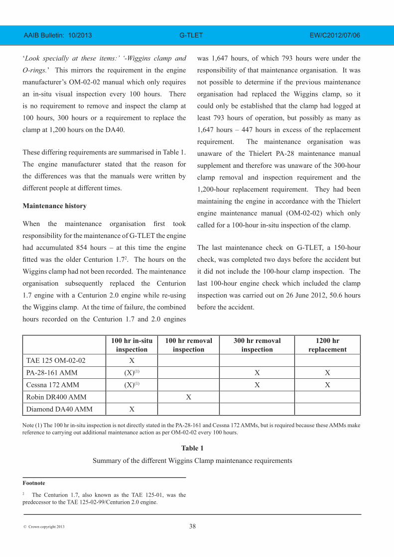
History of clamp failures
The engine manufacturer was aware of only one previous failure of a Wiggins clamp on a Centurion engine and that was on a Cessna 172R, registration SX-CCA, in 2010. During this incident the aircraft suffered a loss of power during the climb, but was able to turn back and land at the airfield. The clamp on SX-CCA was found to have cracked perpendicular to the main cracks found on the G-TLET and G-BZLH clamps (Figure 7). There was evidence of dark-coloured fretting damage on the inside of the clamp similar to G-TLET and G-BZLH. The engine manufacturer carried out an examination of the engine and noted that the mating section of the turbo charger compressor had a partially broken lip where the O-ring was fitted. Because the fracture surface was dirty they concluded
that it was older than the clean fracture surface on the clamp. Loss of this mating section would result in tilting of the two interconnecting pipes which would result in a high load being transferred to the clamp and could cause it to fail. The manufacturer concluded that the clamp failure was caused by the mating surface failure, which may have been caused by use of improper tooling, based on surface damage witness marks near the failure. No metallurgical examination of the fracture surfaces was carried out.
Details of previous clamp type
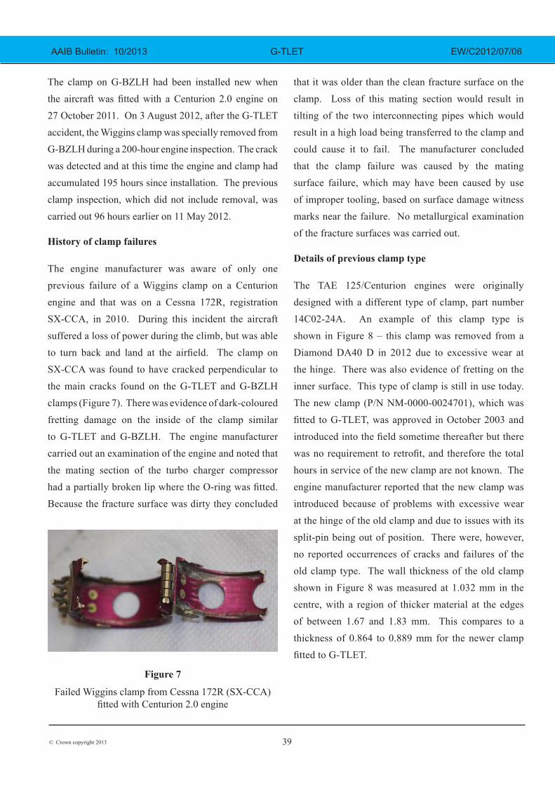
The TAE 125/Centurion engines were originally designed with a different type of clamp, part number 14C02-24A. An example of this clamp type is shown in Figure 8 – this clamp was removed from a Diamond DA40 D in 2012 due to excessive wear at the hinge. There was also evidence of fretting on the inner surface. This type of clamp is still in use today. The new clamp (P/N NM-0000-0024701), which was fitted to G-TLET, was approved in October 2003 and introduced into the field sometime thereafter but there was no requirement to retrofit, and therefore the total hours in service of the new clamp are not known. The engine manufacturer reported that the new clamp was introduced because of problems with excessive wear at the hinge of the old clamp and due to issues with its split-pin being out of position. There were, however, no reported occurrences of cracks and failures of the old clamp type. The wall thickness of the old clamp shown in Figure 8 was measured at 1.032 mm in the centre, with a region of thicker material at the edges of between 1.67 and 1.83 mm. This compares to a thickness of 0.864 to 0.889 mm for the newer clamp fitted to G-TLET.
Figure 7
Failed Wiggins clamp from Cessna 172R (SX-CCA) fitted with Centurion 2.0 engine
The maintenance organisation commented that the location of the clamp meant that it was difficult to detect a crack in the clamp without removing it. However, they also considered that repeatedly removing the clamp to inspect it could introduce other problems so they recommended that the clamp should be made stronger such that it was less susceptible to cracking. Since the G-TLET accident they have revised their 100-hour engine check schedule to call for a removal and inspection of the Wiggins clamp and they have initiated a 1,200-hour clamp replacement requirement for all aircraft types, in accordance with the PA-28 AMM supplement.
Analysis
At the time of the accident, and during the investigation, the engine manufacturer was known as Thielert Aircraft Engines GmbH. In July 2013, however, the diesel aircraft engine and manufacturing assets of this company changed ownership and were added to the Continental Motors Group as Technify Motors
GmbH. The Safety Recommendations in this report
are, therefore, addressed to Technify Motors GmbH.
The loss of power in G-TLET was caused by failure of
the Wiggins clamp between the turbocharger compressor
outlet and the turbo pipe assembly. The clamp had
failed due to a fatigue crack that had initiated at multiple
sites on the inner surface and then propagated through
the thickness of the sidewall. No pre-existing material
defects were identified and the clamp wall thickness was
within specification. There was significant fretting wear
on the inner surface so it was possible that loads due
to vibration initiated the fatigue crack. These vibratory
loads would have been superimposed on any loads from
the compressed air passing through the angled turbo
pipe assembly. It is also possible that a misalignment
of the pipes during installation could have induced an
additional pre-load on the clamp. It was not possible to
determine when the crack had formed but the clamp had
been in use for at least 793 hours and possibly as many
as 1,647 hours – 447 hours in excess of the replacement
requirement. The maintenance organisation had been
unaware of both the 1,200-hour replacement requirement
and the 300-hour ‘remove and inspect’ requirement.
Had the clamp been removed for an inspection at the
last 300–hour check the crack might have been detected,
unless it had initiated after that inspection.
The evidence from the clamp from G-BZLH indicates
that cracking can initiate in under 300 hours. This clamp
had only accumulated 195 hours and it had started to
crack in fatigue in the same manner as the clamp on
G-TLET. If the crack had gone undetected the clamp
probably would have failed with consequent loss of
power. The maintenance organisation stated that they
had detected the crack on the G-BZLH clamp only
because they had removed it following the accident
to G-TLET. There was no requirement to remove it
Figure 8
Older style clamp (P/N 14C02-24A) which was removed from a Diamond DA40 D in 2012 due to
because only an in-situ inspection was required every 100 hours. G-BZLH had undergone a 100-hour engine check 96 hours before the crack was detected and during this in-situ clamp inspection no crack was detected. Similarly, on G-TLET a maintenance check involving an in-situ clamp inspection was carried out 50.6 hours before the accident and no crack was detected. Since the crack initiates on the inside of the clamp and propagates outwards the only way to catch the crack early is to remove it and inspect the inside.
Although this clamp was introduced in 2003, there was no requirement to retrofit; therefore, the in-service hours of the new clamp and the failure rate are not known.
The old-style clamp, which is still in use, has not suffered any reported cracks or failures. It is possible that this is due to its thicker sidewall or it could be due to vibration loads being absorbed by the hinge, which results in a ‘worn hinge’ problem but alleviates stress that might otherwise initiate a crack.
The TAE 125/Centurion engines can be fitted to the Piper PA-28, the Cessna 172, the Robin DR400 and the Diamond DA40 but the maintenance requirements for the clamp are not consistent. One only requires a 100-hour in-situ inspection, one requires a 100-hour removal inspection, some require a 300-hour removal inspection and some require a 1,200-hour replacement. The engine manufacturer could not provide a reason for the different requirements, except to comment that they were drafted by different people; the engine manufacturer was not able to state which inspection requirements were the most appropriate.
Because of the hazard associated with the loss of power following the failure of the Wiggins clamp, the following three Safety Recommendations are made.
Safety Recommendation 2013-018
It is recommended that Technify Motors GmbH, as the STC holder, informs operators of Piper PA-28, Cessna 172 and Robin DR400 aircraft fitted with TAE 125-01 and 125-02 engines that the Wiggins clamp (P/N NM-0000-0024701) is susceptible to cracking, which can lead to clamp failure and significant power loss. Furthermore, as TC holder they should inform Diamond Aircraft Industries of the same.
Safety Recommendation 2013-019
It is recommended that Technify Motors GmbH establishes a consistent and suitable inspection and/or replacement interval for Wiggins clamp (P/N NM-0000-0024701) to be specified in the engine maintenance manuals and the aircraft maintenance manuals for which it holds the Supplemental Type Certificate, to maximise the likelihood that cracks in the clamp are detected before they propagate to failure.
Safety Recommendation 2013-020
It is recommended that Technify Motors GmbH re-assesses the vibration and loading conditions at the clamp and selects an alternate clamp design if necessary to ensure that it is not susceptible to cracking and failure during normal operations.