ACCIDENT SIMULATION WITH by John C. Vigil and Richard J. Pryor An easy-to-use systems code can simulate the entire course of an accident in any light-water reactor system. Its predictive capabilities are being applied to current reactor-safety issues. 36 I magine using an erector set to con- struct models of water-cooled reac- tors with any specified design. Im- agine, too, that these are working models that can reproduce the behavior of full- scale reactors under accident as well as normal conditions. Such an erector set has been developed at Los Alamos and is available for use by researchers and engineers in the reactor community. Known as TRAC, for transient reactor analysis code, it consists of a large set of computer subprograms that can be put together to simulate the complex phenomena that may occur during any specified transient in any realistic reactor design. There are subprograms for the reactor components—the reactor core, the pipes, the pressurizer, the valves, the steam generators, the pumps, and the accumulators—and others for the physi- c al processes—steam-water fluid dynamics, heat generation in the core, and heat transfer between the two phases of the coolant and between the coolant and the solid structures. When as- sembled into a large systems code and run on a high-speed computer, these subprograms simulate numerically the complete course of reactor transients, most notably the loss-of-coolant acci- dent. Los Alamos was asked to develop this versatile computer code to provide re- alistic predictions of reactor response to a large-break loss-of-coolant accident. The Laboratory began this task in early 1975, and less than three years later, TRAC became the first program to pro- vide a continuous analysis of all phases of a loss-of-coolant accident in a full- scale four-loop pressurized-water reac- tor. Since then, other versions of TRAC have been developed with emphasis on either shorter running time or more detailed analysis. In addition, TRAC was the basis of a detailed version for boiling- water reactors developed at Idaho Na- tional Engineering Laboratory. The accuracy of the most recent ver- LOS ALAMOS SCIENCE
Transcript
ACCIDENT SIMULATION WITHby John C. Vigil and Richard J. Pryor
An easy-to-use systemscode can simulate the
entire course of anaccident in any
light-water reactorsystem. Its predictivecapabilities are being
applied to currentreactor-safety issues.
36
Imagine using an erector set to con-struct models of water-cooled reac-tors with any specified design. Im-
agine, too, that these are working modelsthat can reproduce the behavior of full-scale reactors under accident as well asnormal conditions. Such an erector sethas been developed at Los Alamos andis available for use by researchers andengineers in the reactor community.Known as TRAC, for transient reactoranalysis code, it consists of a large set ofcomputer subprograms that can be puttogether to simulate the complexphenomena that may occur during anyspecified transient in any realistic reactordesign. There are subprograms for thereactor components—the reactor core,the pipes, the pressurizer, the valves, thesteam generators, the pumps, and theaccumulators—and others for the physi-c al processes—steam-water fluiddynamics, heat generation in the core,and heat transfer between the two phasesof the coolant and between the coolant
and the solid structures. When as-sembled into a large systems code andrun on a high-speed computer, thesesubprograms simulate numerically thecomplete course of reactor transients,most notably the loss-of-coolant acci-dent.
Los Alamos was asked to develop thisversatile computer code to provide re-alistic predictions of reactor response toa large-break loss-of-coolant accident.The Laboratory began this task in early1975, and less than three years later,TRAC became the first program to pro-vide a continuous analysis of all phasesof a loss-of-coolant accident in a full-scale four-loop pressurized-water reac-tor. Since then, other versions of TRAChave been developed with emphasis oneither shorter running time or moredetailed analysis. In addition, TRAC wasthe basis of a detailed version for boiling-water reactors developed at Idaho Na-tional Engineering Laboratory.
The accuracy of the most recent ver-
LOS ALAMOS SCIENCE
I
sion of TRAC (TRAC-PD2) forlarge-break accident analysis has beenextensively tested against small-scale ex-periments and integral tests at facilitiessuch as LOFT and Semiscale. The firstfull-scale test of TRAC was its analysisof the first few hours (before the corewas damaged) of the Three Mile Islandaccident. The results showed that thecode is also applicable to small-break,multiple-failure accidents. Current ap-plications of TRAC are in this area. Tobetter handle these complex accidents, anew version of the code is being de-veloped to include models for the tur-bine-generator and feedback controls.Numerical methods are also being im-proved to increase computing speed sothat long-duration transients can beanalyzed more efficiently.
TRAC and the Bounding Accident
Although extremely unlikely, theloss-of-coolant accident resulting from a
LOS ALAMOS SCIENCE
large, double-ended break in the primarycoolant system of a pressurized-waterreactor (Fig. 1) has long been consideredthe bounding accident—the worst thatcould happen—and the accident againstwhich the performance of emergencycore-cooling systems is tested in thelicensing process.
TRAC was designed specifically tosimulate the large-break accident. Al-though this large systems code onlyapproximates the intricate geometry ofthe plant and the physical processes thatoccur, it does simulate many complexphenomena that have been identified asimportant through small-scale experi-ments and more detailed computer stud-ies of individual components.* Amongthese phenomena are critical flow, multi-dimensional effects, countercurrent fluidflow, fuel-rod quenching, and steambinding.
The course of a large-break accidenthas three main phases: blowdown, dur-ing which the primary system depres-
surizes and the coolant flashes to steam;bypass/refill, during which emergencycooling water refills the lower plenum tothe bottom of the fuel rods; and reflood,during which water refills the core andcools the fuel rods.
TRAC analyses of a s tandardfour-loop pressurized-water reactor pre-dict that, if all systems operate as de-signed, the fuel rods will be cooled withinapproximately three minutes and that nocore damage will occur. These calcu-lations also show that the NRC-specifiedassumptions are indeed conservative.For example, emergency cooling waterwill penetrate the lower plenum andreflood the core more rapidly than pre-dicted by the licensing analyses.
Accident details and TRAC predic-tions outlined below will introduce thereader to the complex fluid-dynamicsand heat-transfer problems that TRAChas addressed.
*See “Detailed Studies of Reactor Components”is this issue.
37
To Turbine
STEAMGENERATOR
Feedwater Inlet
Primary Pump
(b) REACTORVESSEL
Fig. 1. Coolant flow pattern through the primary system of apressurized-water reactor (a) during normal operation whencoolant flows down the downcomer and up through the coreand (b) early in blowdown when coolant flows up thedowncomer and out the broken cold leg.
38 LOS ALAMOS SCIENCE
ACCIDENT SIMULATION WITH TRAC
BLOWDOWN. Following a sudden,large break in a cold-leg pipe, the largepressure difference between the primarysystem (150 bars*) and the containment(-1 bar) forces water rapidly out thebreak (see Fig. 1). The rate at whichwater escapes is limited by the chokingphenomenon, or critical flow. At first,the pressure is high enough that onlysubcooled water is discharged. Then,when the primary system pressure hasfallen to the saturation pressure. thecoolant flashes to steam and a two-phasemixture is discharged. Primary pumpperformance degrades drastically duringthis period.
During blowdown, all the water in thepressurizer, which maintains primarysystem pressure during normal opera-tion, discharges into one of the hot legs.
The high-pressure injection system,consisting of low-flow-capacity pumps,turns on automatically early in blow-down and injects emergency coolant intothe cold legs.
During all phases of the accident, theheat that may damage the core comesfrom two sources, reverse heat transferin the steam generators and decay heatin the core. Reverse heat transfer occursas the primary system pressure fallsbelow that of the secondary system (-70bars); the primary coolant is then heatedby the secondary system. This ac-celerates “voiding,” or coolant vapor-ization, in the core, a process that con-siderably reduces the efficiency of heattransfer from the fuel rods to thecoolant. Although fission is halted auto-matically as the water in the core vapor-izes (voiding has a very large andnegative effect on the reactivity of the
LOS ALAMOS SCIENCE
ColdLeg
Fig. 2. Steam-water flows in the downcomer during bypass when emergency coolantswirls around the downcomer and out the cold-leg break.
core), decay heat continues to be gener-ated by fission products. The fuel rodsdry and their temperature begins to rise,although some cooling is provided by thesurrounding two-phase mixture.
For a large, double-ended break in acold leg, TRAC predicts that blowdownlasts approximately 15 seconds. Thecalculations also show that it is duringthis phase of the accident that the fuelcladding reaches its maximum tem-perature, -950 kelvin. This temperatureis considerably lower than the maximum(-1500 kelvin) allowed by the licensingguidelines.
During blowdown, some of the waterin the lower plenum boils away or isswept out by high-velocity steam movingdown through the core and up the down-comer to the broken cold leg. The
amount of water remaining in the lowerplenum determines the duration of thenext phase of the accident.
BYPASS/REFILL. The second phaseof the accident begins when the primarysystem pressure falls below that of thenitrogen in the accumulators (45 bars).Then, the check valves that normallyisolate the accumulators from the prima-ry system open, and expanding nitrogenforces water into the downcomerthrough the intact cold leg,
TRAC calculations show that, at first,water from the accumulator cannotreach the lower plenum. Instead, it isswept around the downcomer and outthe broken cold leg (Fig, 2) by thecountercurrent flow of steam. The steamis generated by flashing as the primary
39
system pressure falls and by boiling asheat is transferred from structural mate-rials. Vapor flow toward the subcooledaccumulator water increases as con-densation decreases the local pressure.Water from the accumulator continuesto bypass the lower plenum for approx-imately 10 seconds. Then, as the coun-tercurrent steam velocities decrease, wa-ter begins to penetrate the lower plenumand refill begins.
During refill, multidimensional effectscan occur in the downcomer with waterflowing down one portion and steammoving up the diametrically oppositeportion. Alternate “storage” and “dump-ing” of emergency coolant also takesplace as the water’s downward flow isheld up periodically until a quantitycollects that is sufficient to overcome theupward steam pressure. Refill lasts forabout 10 seconds and ends when thewater level in the lower plenum reachesthe bottom of the fuel rods. To providethis realistic description of bypass/refill,T R A C uses a two - fluidthermal-hydraulics model and at least atwo-dimensional representation of thedowncomer geometry.
REFLOOD. Emergency core coolingculminates in the several minutes ofreflood during which water refills thereactor vessel and quenches the fuelrods. The primary source of emergencycoolant for reflood is water pumped intothe cold legs by the low-pressure injec-tion system. This system activates auto-matically when the primary system pres-sure falls below about 6 bars.
At the beginning of reflood, the fuelrods are relatively hot because heattransfer has not been very effective dur-ing most of blowdown and all of
40
Falling-FilmQuench Front
L Bottom-FloodingQuench Front
through the core and from the top by liquid films falling through the upper core-support plate.
LOS ALAMOS SCIENCE
ACCIDENT SIMULATION WITH TRAC
trained droplets help to cool the rods athigher elevations. (This effect, as well asaxial heat conduction in the rods fromunquenched to quenched regions, iscalled precursory cooling.)
The entrained droplets are responsiblefor top-down quenching. As they risethrough the upper plenum, they de-entrain, or deposit, on various structures
DropletsVaporize in
and IncreaseBack Pressure onLiquid in Core
To Break
Fig. 4, Steam binding during reflood. The pressure
Core Liquid Level
created by vaporization ofentrained droplets in the steam generator opposes the flow of emergency coolant to thecore.
bypass/refill. Consequently, when water temperature, that is, the rods arefirst covers the bottom of the fuel rods, it quenched. Quenching progresses fromis unable to wet the cladding surface bottom to top as the core is refloodedbecause heat transfer is predominantly but, as explained below, some top-downby film boiling. Eventually, the cladding quenching also occurs at the same timetemperature falls below the minimum (Fig. 3).stable film-boiling temperature, the liquid The quenching process releases awets the surface, the fuel rods cool by large amount of heat to the refloodingthe efficient mechanism of nucleate boil- water and causes steam to form. Theing, and their temperature at that eleva- steam carries water droplets upward as ittion drops sharply to near the water rises between the fuel rods; these en-
LOS ALAMOS SCIENCE
support plate. At first, water from thepool cannot flow down to quench therods because steam is moving upwardthrough the holes in the upper core-support plate. This phenomenon is simi-lar to that occurring in the downcomerduring bypass. At some point, however,water films penetrate the holes and beginto quench the fuel rods from the top.Top-down quenching by falling filmstakes place first at the core peripherywhere decay heat is lowest. Tracking ofthe quench fronts due to both bottomflooding and falling films was probablythe most difficult technical problem wefaced in modeling a large-break accident.
Reflooding, and hence quenching, canbe retarded by the phenomenon knownas steam binding (Fig. 4). The drivingforce for reflooding the core is the dif-ference between the water levels in thedowncomer and the core. This force canbe counterbalanced by an increase incore pressure produced as entrained wa-ter droplets are carried to the steamgenerator and vaporized by reverse heattransfer.
As described later, separate-effectstests for the reflood phase indicate thatthe TRAC droplet-entrainment modelmay need improvement, but, in general,the treatment of the steam-waterdynamics during reflood is in agreementwith experiment.
41
Code Designand Computational Models
TRAC was to be a benchmark systemscode for large-break accidents, but itsflexible design makes it suitable forstudying many types of transients. Forexample, TRAC-PD2 has been used suc-cessfully to analyze the first few hours ofthe Three Mile Island accident, small-break loss-of-coolant transients in theLOFT facility, and loss-of-feedwaterscenarios in full-scale pressurized-waterreactors. The fast-running version(TRAC-PF1) currently under develop-ment at Los Alamos is designed toaddress these transients more efficientlyand accurately.
TRAC owes this enormous flexibilityto its completely modular design. Byjoining the modules (subprograms) in ameaningful way, the user can simulate awide range of phenomena, from a simpleblowdown to a multiple-failure transient.The user need supply only the problemgeometry and the boundary conditions.
Figure 5 shows the structure ofTRAC. including component and func-tional subprograms. To specify the prob-lem geometry, the user instructs the codeto join component subprograms thatcorrespond to specific reactor compo-nents. TRAC includes component sub-programs sufficient to model primaryloops in their entirety and secondaryloops except for the turbine-generatorand condenser, which can only be ap-proximated. Also available are subpro-grams to model boundary conditions atbreaks and fills.
Each component subprogram auto-matically accesses functional subpro-grams that compute the important physi-cal processes occurring within the com-
Fig. 5. TRAC is divided into five main subprograms, each of which handles a majoraspect of the problem. INPUT accepts the user’s description of the problem, INITcalculates quantities required for analysis that need not be supplied as input, STEADYcalculates pretransient, or steady-state, conditions of the reactor, TRANS calculatesthe response of the reactor to the transient, and EDIT provides output. Within each ofthese main subprograms are subprograms that deal with particular reactor compo-nents. For all but TRANS, only the pipe component subprogram is shown; for TRANS,all the component and some important functional subprograms are listed. Eachcomponent subprogram accesses appropriate functional subprograms for relevantcalculations.
Fig. 6. Main functional subprograms accessed by PIPE to calculate the fluid dynamicsand heat transfer within a pipe.
42 LOS ALAMOS SCIENCE
ACCIDENT SIMULATION WITH TRAC
3-D Mesh Cells
\
Fig. 7. Typical computational mesh for a vessel and a single coolant loop. In vesselcells, TRAC computes the nuclear heat and its transfer among fuel rods, flowing steamand water, and structural materials. In pipe cells, TRAC computes steam- water flowconditions and heat transfer between the two phases and pipe walls. Other reactorcomponents are treated as variations on a pipe: a pump as a pipe with a momentumsource; a valve as a pipe with a variable flow area; a pressurizer as a vertical pipeclosed at one end with a heater/sprayer and a sharp steam-water interface; a steamgenerator as a pipe within another pipe; and an accumulator as a vertical pipe closedat one end with a sharp interlace between water and pressurized nitrogen.
ponent: steam-water fluid dynamics, (DFID) to solve the one-dimensionalheat transfer, and, in the vessel compo- fluid-dynamics equations. A pipe sub-nent, neutronics, or nuclear heat gener- program calls on other functional sub-ation. For example, all component sub- programs to obtain additional informa-programs except that for the vessel ac- tion required for solution of these equa-cess the same functional subprogram tions, such as relative velocity of the two
phases and heat-transfer coefficients be-tween pipe walls and vapor or liquid(Fig. 6).
The reactor vessel and its internalstructures (downcomer, core, upper andlower plena, and so on) are representedin three- or two-dimensional geometry atthe user’s choice. Components outsidethe vessel are represented in one-dimensional geometry. Figure 7 shows avessel and a single coolant loop as-sembled into computational cells withTRAC component subprograms.
TWO-PHASE FLUID DYNAMICS.The TRAC approach to modeling thesteam-water dynamics is described in thepreceding article. A two-fluid modelbased on conservation of mass, momen-tum, and energy for the liquid and vaporpermits treatment of nonhomogeneousand nonequilibrium two-phase flow.That is, the liquid and vapor phases canmove with different velocities and canhave different temperatures, a situationthat occurs during emergency coolantinjection when superheated vapor andsubcooled water flow in opposite direc-tions. Other less-advanced codes requirethat the two phases have the samevelocity or that one phase be at thesaturation temperature.
For lack of a real theory, the con-stitutive relations are approached em-pirically. These relations describe theexchange of mass. energy, and momen-tum between steam and water and be-tween solid structures and steam-watercoolant. The exchange rates depend oninformation not available from the two-fluid equations, namely, the flow regimein effect. Figure 8 shows the importantflow regimes for upward flow through avertical array of fuel rods. TRAC in-
LOS ALAMOS SCIENCE 43
Fig. 8. Flow regimes and associated heat-trarqfer regimes for upwardjlow through a vertical array ojjuel rods as (a) low and (b)
high heatjlu,xes.
eludes an empirical flow-regime map
that correlates calculated values of the
vapor fraction and the mass flux with
particular flow regimes. Once the flow
regime is determined, TRAC computes
the exchange rates from empirical
algorithms. This method of handling the
constitutive relations yields acceptable
resuks in agreement with a wide variety
of experiments, but further improvement
of TRAC is expected mainly from in-
creased knowledge in this area.
HEAT TRANSFER. The mechanism
44
for transferring heat between coolant
and structural materials or fuel rods also
depends on the flow regime. Figure 8
also displays the heat-transfer regimes
associated with each flow regime. TRAC
includes models for the following heat-
transfer mechanisms: convection to sin-
gle-phase liquid, nucleate boiling, transi-
tion boiling, film boiling, convection to
single-phase vapor, condensation, and
liquid natural convection.
Temperatures of fuel rods and struc-
tural materials are calculated with heat-
conduction models: a one-dimensional
model for pipes; a one-dimensionallumped-parameter slab model for reactor
vessel structures, such as downcomer
walls and core-support plates; and a
two-dimensional model for fuel rods.
The fuel-rod heat-conduction model
simulates the effects of internal heat
generation, quenching phenomena,
zirconium-steam reactions, and changes
in the size of the gap between cladding
and fuel. The conduction model subpro-
gram automatically divides the fuel rods
LOS ALAMOS SCIENCE
ACCIDENT SIMULATION WITH TRAC
into smaller cells during reflood calcu-lations to provide finer detail for thisphase of a transient. To track the quenchfront, the subprogram also uses dynamicindicators to rezone the rods into asuper-fine mesh that can resolve thelarge axial temperature gradient at thefront.
NUCLEAR POWER GENERATION.
During a transient, power generation inthe core changes with time. TRAC mod-els these changes with two methods. Oneis simply the use of a power-versus-timetable supplied as input by the user. Theother is solution of the point-reactorkinetics equations that describe corepower as a function of time, with totalreactivity as the controlling parameter.Reactivity-feedback effects due tochanges in core-average fuel tem-perature, coolant temperature, andcoolant density are taken into account.Power from fission and fission-productdecay is calculated with 6 delayed-neu-tron groups and 11 decay-heat groups.
The spatial distribution of power inthe core and within the fuel rods isspecified as input and remains fixedduring the transient. This approximationis adequate for all loss-of-coolant tran-sients because fission is halted by void-ing of the core or scramming the reactor.However, for analysis of transientswithout scram, reactivity-insertion acci-dents, and some operational transients,changes in the spatial power distributionmay be important and would require theuse of a space- and time-dependent pow-er generation model.
COMPUTATIONAL TECHNIQUES.The field and constitutive equations aresolved by efficient spatial finite-dif-
LOS ALAMOS SCIENCE
ference techniques. Normally, a semi-implicit time-differencing technique isused for all calculations. This techniqueis subject to the Courant stability limita-tion that restricts the time-step size inregions of high-speed flow (for example,in a broken leg). Therefore, a fullyimplicit time-differencing option is alsoavailable for solution of the one-dimensional flow equations; this optionpermits tine spatial resolution in regionsof high-speed flow without restricting thetime-step size.
To improve convergence, the solutionstrategy for the vessel includes thesetechniques: direct matrix inversion (rath-er than iteration) for vessels with lessthan 80 cells; coarse-mesh rebalance forvessels with more than 80 cells; re-linearization of the vessel equations tocorrect the assignment of a donor cellwhen the fluid velocity changes signduring a time step; and a time-stepbackup procedure when invalid tem-peratures, pressures, or void fractionsare encountered.
A stability-enhancing two-step numer-ical method included in TRAC-PF1 re-moves the Courant time-step limitationand permits analysis of transients of longduration at real time or better. To furtherenhance stability, wall heat transfer istreated more implicitly in this version.
OUTPUT. TRAC produces an ex-traordinary amount of information dur-ing the course of a calculation. At eachstep and for each mesh cell, TRACprovides values for the following vari-ables: fluid pressure, void fraction, tem-peratures and velocities of the twocoolant phases (for vessel cells, the ve-locities are vector quantities), and tem-peratures of solid materials, such as the
cladding. Other variables (for example,mass and momentum fluxes and fluiddensity) can be obtained from thesebasic variables. A versatile graphicspackage is available to help the userdigest this information by producingmovies and a wide variety of plots.
To determine the validity of TRACresults, they must be compared withexperiment, but, unfortunately, velocitiesand temperatures of the two coolantphases cannot be measured accurately.Variables that can be measured directlyand accurately include fluid pressure,mixture temperature, and metal tem-peratures. Indirect and less accuratemeasurements can be made of void frac-tion and steam-water mixture velocities.The number and location of variablesmeasured are necessarily much smallerthan those calculated; furthermore, insome cases, the measurement device cansignificantly perturb the variable beingmeasured.
How Good is TRAC?
The end objective for TRAC is toprovide a credible predictive tool for alllight-water reactor transients. But canwe rely on TRAC predictions of eventsthat have never been measured in full-scale reactors? We believe the answer isyes. The code has been tested againstmany different experiments that span awide range of scales, reactor compo-nents, and geometric arrangements andinvolve most of the important thermal-hydraulic phenomena expected in a full-scale power plant under normal andaccident conditions.
The constitutive relations in TRAC arebased on so-called model developmentexperiments. These are usually small-
45
TABLE I
FACILITIES FOR TRAC ASSESSMENT
Operating Institution Phenomena and PhaseFacility and Location Scale of Accident Studied Descriptiona
Semiscale Mod-1 Idaho National Engineering Laboratory Small System effects during One active andUnited States all accident phases one passive loop
Semiscale Mod-3 Idaho National Engineering Laboratory Small System effects during Full-height core,United States all accident phases two active loops,
and upper-head-injectioncapability
LOBI Commission of the European Small System effects during Two active loopsCommunities, Ispra Establishment blowdown and bypass/ and full-heightItaly refill core
FLECHT Westinghouse Electric Corporation Small Separate effects during Single-bundleUnited States reflood full-height core
FLECHT-SEASET Westinghouse Electric Corporation Small Separate and system Single-bundleUnited States effects during reflood full-height core
and one coolantloop
THTF Oak Ridge National Laboratory Small Heat transfer during Single-bundleUnited States blowdown full-height core
Pipe Blowdown Tests Centro Informazoni Studi Esperienze Small Separate effects during Pipe-wall-heatingItaIy blowdown capabilityAtomic Weapons Research EstablishmentUnited Kingdom
Tube CHF Tests Atomic Weapons Research Establishment Small Steady-state pipe wall Pipe-wall-heatingUnited Kingdom heat transfer over entire capability
range of boiling curve
LOFT Idaho National Engineering Laboratory Intermediate System effects during Nuclear core, oneUnited States all accident phases active and one
passive loop
PKL Gesellschaft fur Reaktorsicherheit m.b.H. Intermediate Separate effects during 340-rod full-heightWest Germany bypass/refill and reflood core and three
coolant loops
CCTF Japan Atomic Energy Research Institute Intermediate Separate effects during 2000-rodJapan bypass/refill and full-height
reflood cylindrical core
Downcomer Tests Creare, Inc. Intermediate Separate effects during Downcomer andUnited States bypass/refill lower plenum withBattelle Columbus Laboratories external steamUnited States source
Marviken 111 Studsvik Energiteknik AB Large Critical flow during Full-scaleSweden blowdown vessel
SCTF Japan Atomic Energy Research Institute Large Separate effects during Full-scaleJapan bypass/refill and reflood (axial and
radial) slabcore
UPTFb Gesellschaft fur Reaktorsicherheit m.b.H Large Separate effects during Full-scaleWest Germany bypass/refill and downcomer and
reflood upper plenumwith internals
aUnless otherwise noted, nuclear processes are simulated by electric heating,bConstruction will begin soon on this facility; TRAC has been used for design analysis.
46 LOS ALAMOS SCIENCE
ACCIDENT SIMULATION WITH TRAC
TABLE H
ASSESSMENT PHENOMENA IN PRESSURIZED-WATER REACTOR COMPONENTS
Component Assessment Phenomena
Core Conductive and convective heat transfer, dryout and rewetting, entrainment and de-entrainment,quench-front propagation, flow topology, multidimensional effects.
Upper plenum and head Entrainment, de-entrainment, and re-entrainment, pool formation and flooding, emergencycoolant injection, liquid inventory, multidimensional effects
Lower plenum Voiding, sweepout, refill, heat transfer by mixing, condensation
Steam generator Heat transfer, steam binding, pressure drop
Pump Head and torque, friction, two-phase degradation
Pressurizer and accumulator Depletion rate
Piping Flow topology, wall heat transfer and friction, flow rate, condensation, critical flow
scale laboratory experiments that ex-plore the basic physical processes as-sociated with two-phase thermalhydraulics: bubble growth, vapor nucle-ation, interphase transfer of mass,momentum, and energy, flow regimevariation, and so on. Such experimentsare being performed at numerous institu-tions, including national laboratories,universities, and industrial research labo-ratories. Application of such informationto full-scale reactors is yet incomplete.
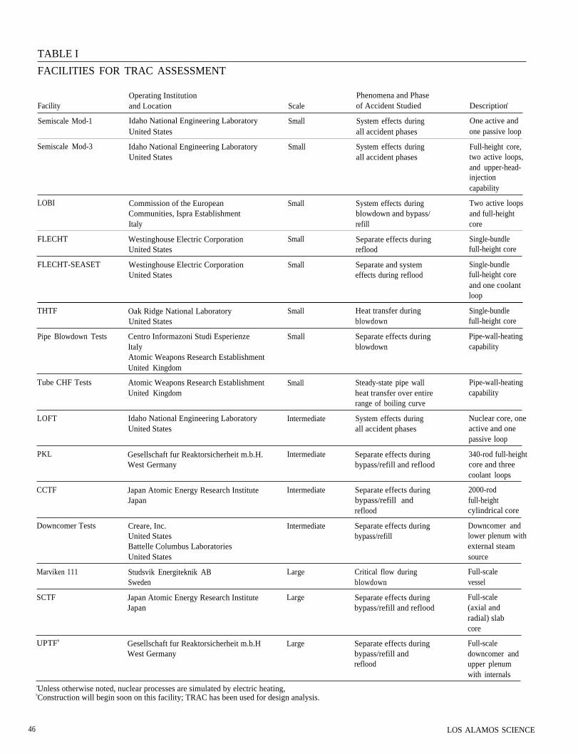
Testing of TRAC itself is done bycomparison with two basic types ofexperiments: separate-effects experi-ments designed to study a single phase ofa loss-of-coolant accident or the re-sponse of a single reactor componentand integral experiments that involve allthe major components of the primarysystem during more than one phase ofthe transient. Some of the experimentalfacilities used to test TRAC are described
LOS ALAMOS SCIENCE
in Table I. Table H lists the importantphenomena associated with pressurized-water reactor components that are stud-ied experimentally and then comparedwith TRAC predictions. The com-parisons lead to new experiments andimproved versions of the code.
T R A C-P D2, the latest version to bereleased to the reactor community, wastested against separate-effects and inte-gral tests covering a wide range of scalesand was found to do a credible joboverall . To i l lustrate the code’sperformance at the time of release, wepresent results from a separate-effectstest for the reflood phase, the mostdifficult phase of an accident to simulate.
REFLOOD TEST. FLECHT, the full-length emergency-cooling heat-transferfacility, was designed to study heattransfer, quench-front propagation, anddroplet entrainment and de-entrainment
47
during the reflood phase of a loss-of-coolant accident. FLECHT consists of asingle fuel bundle containing approx-imately 100 full-length fuel rodsmounted in a flow housing with upperand lower plenum regions (Fig. 9). Thebundle and housing are electrically heat-ed until the bundle is covered withsaturated steam but the lower plenum isfull of water. Reflood is initiated byinjecting water into the lower plenumwhen the desired maximum rod tem-perature is reached. Electric heating isdecreased during reflood to simulate de-cay heat, Figure 10 compares TRAC
predictions and experimental values forthe quench-front location as a functionof time. (The quench front is the point atwhich the fuel-rod temperature has drop-ped rapidly to near that of the refloodingwater.) Note that complete quenchingoccurred earlier than predicted byTRAC. This discrepancy is attributed toradiant heat transfer from the heatedrods to the housing and to unheatedrods, an effect not included in TRAC
because it is unimportant for a full-scalepressurized-water reactor.
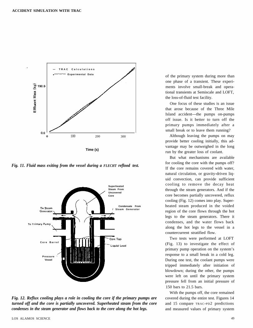
The mass of fluid exiting from theupper plenum region was also measuredand is compared with calculated valuesin Fig. 11. The good agreement appearsto indicate an acceptable entrainmentmodel in TRAC. However, there is someevidence from these and other experi-ments that more de-entrainment in theupper plenum is needed to improve thecalculated results for the top-downquench front.
INTEGRAL TESTS OF SMALL-BREAK ACCIDENTS. Following the re-lease of TRAC-PD2, we have continuedto test the code against integral experi-ments that involve all major components
48
UPPERPLENUM
ElectricallyHeated
Rods
LOWERPLENUM
supply
(a)
Fig. 9. Schematic diagram of (a) FLECHT and (b) its division into computationalcells in the TRAC model. FLECHT’S simulation of a core consists of a single bundle ofelectrically heated, full-length rods in a 10 by 10 array. Because multidimensionaleffects were not the focus of the experiment, the vessel was treated as a slab (an optionavailable in TRAC) and the two-fluid equations were formulated and solved in onedimension, along the vessel axis.
100 200 300
Time (s)
Fig. 10. Quench-front propagation during a reflood test at FLECHT.
LOS ALAMOS SCIENCE
ACCIDENT SIMULATION WITH TRAC
— T R A C C a l c u l a t i o n s
● ***”**”** Exper imental Data
o 100 200 300
Time (s)
Fig. 11. Fluid mass exiting from the vessel during a FLECHT reflood test.
To PI
C o r e B a r r e l -
Pressure ‘Vessel L
SuperheatedSteam FromUncoveredCore
Condensate From/ Steam Generator
Fig. 12. Reflux cooling plays a role in cooling the core if the primary pumps areturned off and the core is partially uncovered. Superheated steam from the corecondenses in the steam generator and flows back to the core along the hot legs.
LOS ALAMOS SCIENCE
of the primary system during more thanone phase of a transient. These experi-ments involve small-break and opera-tional transients at Semiscale and LOFT,the loss-of-fluid test facility.
One focus of these studies is an issuethat arose because of the Three MileIsland accident—the pumps on-pumpsoff issue. Is it better to turn off theprimary pumps immediately after asmall break or to leave them running?
Although leaving the pumps on mayprovide better cooling initially, this ad-vantage may be outweighed in the longrun by the greater loss of coolant.
But what mechanisms are availablefor cooling the core with the pumps off?If the core remains covered with water,natural circulation, or gravity-driven liq-uid convection, can provide sufficientcooling to remove the decay heatthrough the steam generators. And if thecore becomes partially uncovered, refluxcooling (Fig. 12) comes into play. Super-heated steam produced in the voidedregion of the core flows through the hotlegs to the steam generators. There itcondenses, and the water flows backalong the hot legs to the vessel in acountercurrent stratified flow.
Two tests were performed at LOFT(Fig. 13) to investigate the effect ofprimary pump operation on the system’sresponse to a small break in a cold leg.During one test, the coolant pumps weretripped immediately after initiation ofblowdown; during the other, the pumpswere left on until the primary systempressure fell from an initial pressure of150 bars to 21.5 bars.
With the pumps off, the core remainedcovered during the entire test. Figures 14and 15 compare TRAC-PD2 predictionsand measured values of primary system
49
STEAM WICK OPENINGGENERATOR
Fig. 13. Major components of LOFT, anintermediate-scale facility for integralloss-of-coolant tests. Volume, power, and
flow and break areas are scaled at 1 to60. LOFT is unusual in that it contains areal nuclear core rather than electricheaters. Breaks are simulated by thequick-opening valves. The suppressionvessel collects the lost coolant and con-trols the back pressure on the vessel.
50
100
o 5000
Time (s)
Fig. 14. Primary system pressures during a simulated small-break loss-of-coolantaccident at LOFT with the primary pump turned off immediately.
LOS ALAMOS SCIENCE
ACCIDENT SIMULATION WITH TRAC
Fig. 15. Cladding temperatures during a simulated small-break loss-of-coolantaccident at LOFT with the primary pump turned off immediately.
Fig. 16. Primary system pressures during a simulated small-break loss-of-coolantaccident at LOFT with the primary pumps operating until about 2400 seconds.
pressure and cladding temperature. Theinitial rapid pressure decrease (Fig. 14)corresponds to the subcooled portion ofblowdown; boiling and flashing accountfor the slower decrease later. At approx-imately 2300 seconds, the break isisolated (closed), and the pressure beginsto increase and stabilizes at about 5000seconds. At this point, the heat removedby natural circulation balances the decayheat. The cladding temperature (Fig. 15)follows the saturation temperature of thefluid and stabilizes at about 90 kelvinbelow the initial temperature.
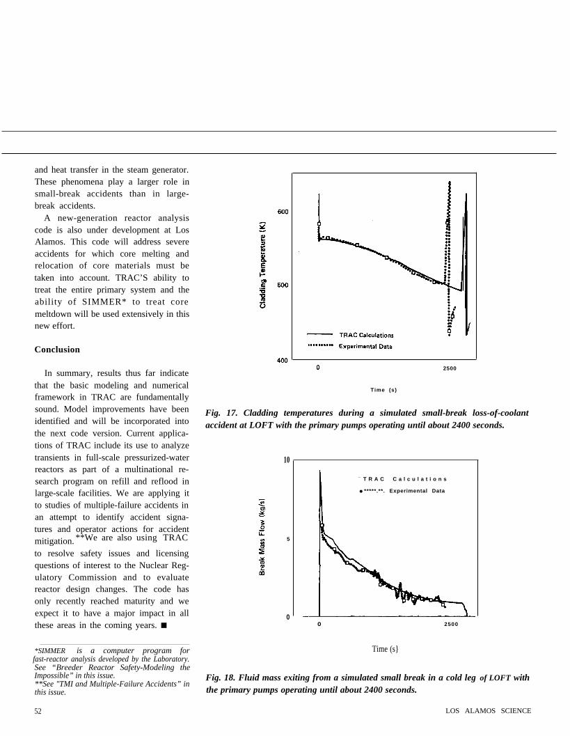
During the pumps-on test, the core iscooled satisfactorily by the two-phasemixture until the pumps are turned off atabout 2400 seconds. Note that duringthis period, the pressure and claddingtemperature histories (Figs. 16 and 17)are very similar to those for the pumps-off test. The mass flow out the break(Fig. 18) is, of course, greater with thepumps on. When the pumps are tripped,steam and water separate and the upperportion of the core is uncovered. Thisresults in a rapid rise in cladding tem-perature. (A similar situation occurredduring the Three Mile Island accidentwhen the primary pumps were turned offby the operators). When the claddingtemperature reached 590 kelvin, the testwas terminated by injecting emergencycoolant from the accumulator. BecauseTRAC slightly underpredicted the rate ofprimary system pressure decrease, it alsopredicted that the pump trip and result-ing temperature excursion occurred later(see Fig. 17). Otherwise, the calculatedand measured histories are in excellentagreement.
These studies are continuing and thenew faster-running version of TRAC(TRAC-PF1) should be able to simulatethese long (several hours) transientsmore accurately and economically. Itwill include models of stratified counter-current flow and feedback controls, im-proved models of flow at a break, and amore detailed representation of fluid flow
LOS ALAMOS SCIENCE
and heat transfer in the steam generator.These phenomena play a larger role insmall-break accidents than in large-break accidents.
A new-generation reactor analysiscode is also under development at LosAlamos. This code will address severeaccidents for which core melting andrelocation of core materials must betaken into account. TRAC’S ability totreat the entire primary system and theability of SIMMER* to treat coremeltdown will be used extensively in thisnew effort.
Conclusion
In summary, results thus far indicatethat the basic modeling and numericalframework in TRAC are fundamentallysound. Model improvements have beenidentified and will be incorporated intothe next code version. Current applica-tions of TRAC include its use to analyzetransients in full-scale pressurized-waterreactors as part of a multinational re-search program on refill and reflood inlarge-scale facilities. We are applying itto studies of multiple-failure accidents inan attempt to identify accident signa-tures and operator actions for accidentmitigation. **We are also using TRAC
to resolve safety issues and licensingquestions of interest to the Nuclear Reg-ulatory Commission and to evaluatereactor design changes. The code hasonly recently reached maturity and weexpect it to have a major impact in allthese areas in the coming years. ■
*SIMMER is a computer program forfast-reactor analysis developed by the Laboratory.See “Breeder Reactor Safety-Modeling theImpossible” in this issue.**See "TMI and Multiple-Failure Accidents” inthis issue.
52
2500
Time (s)
Fig. 17. Cladding temperatures during a simulated small-break loss-of-coolantaccident at LOFT with the primary pumps operating until about 2400 seconds.
10
5
0
— T R A C C a l c u l a t i o n s
● *****.**. Experimental Data
o 2500
Time (s}
Fig. 18. Fluid mass exiting from a simulated small break in a cold leg of LOFT withthe primary pumps operating until about 2400 seconds.
LOS ALAMOS SCIENCE
ACCIDENT SIMULATION WITH TRAC
AUTHORS
in 1961 from the New Mexico Institute of Mining andTechnology, where he graduated with highest honors; heearned his Ph.D. in nuclear engineering in 1966 from theUniversity of New Mexico. He was awarded a SpecialFellowship in Nuclear Science and Engineering by theAtomic Energy Commission in 1961 and was listed inAmerican Men of Science in 1968 and in Who’s Who inthe West in 1970. He has been with the Laboratory since1963 and has specialized in the development and applica-tion of large computer codes for reactor analysis. Beforeassuming his present position as Assistant to the As-sociate Director for Energy Programs, he was AssistantEnergy Division Leader for Reactor Safety.
Richard J. Pryor joined the Laboratory in 1976 and iscurrently the Program Manager for Nuclear ReactorPrograms. Before this assignment, he was Leader of theCode Development Group, which is responsible fordevelopment of TRAC. He received a B.S. in physicsfrom Pennsylvania State University in 1965 and a Ph.D.in nuclear physics from the University of Pittsburgh in1970. He is a member of the American Physical Societyand the American Nuclear Society.
Further Reading
“TRAC-P1: An Advanced Best Estimate Computer Program for PWR LOCA Analysis. Vol. I.Methods, Models, User Information, and Programming Details,” Los Alamos Scientific Laboratoryreport LA-7279-MS, Vol. I (June 1978).
“TRAC-PIA: An Advanced Best-Estimate Computer Program for PWR LOCA Analysis,” LosAlamos Scientific Laboratory report LA-7777-MS (May 1979).
“TRAC-PD2:An Advanced Best-Estimate Computer Program for Pressurized Water Reactor Loss-of-Coolant Accident Analysis,” Los Alamos National Laboratory report LA-8709-MS (April 1981).
J. H. Mahaffy, “A Stability Enhancing Two-Step Method for One-Dimensional Two-Phase Flow,” LosAlamos Scientific Laboratory report LA-795l-MS (August 1979).
J. C. Dallman and W. L. Kirchner, “De-entrainment on Vertical Elements in Air Droplet Cross Flow,”American Society of Mechanical Engineers report 80-WA/HT-46 (November 1980).
T. D. Knight (Compiler), “TRAC-PD2 Developmental Assessment,” Los Alamos National Laboratoryreport (in preparation).
E. R. Rosal, L. E. Hochreiter, M. F. McGuire, and M. C. Krepinevich, “FLECHT Low Flooding RateCosine Test Series Data Report,” Westinghouse Electric Corporation report WCAP-8651 (1975).
L. T. L. Dao and J. M. Carpenter, “Experiment Data Report for LOFT Nuclear Small Break ExperimentL3-5/L3-5A,” EG&G Idaho, Inc. report EGG-2060 (November 1980).
P. D. Bayless and J. M. Carpenter, “Experiment Data Report for LOFT Nuclear Small BreakExperiment L3-6 and Severe Core Transient Experiment L8-1,“ EG&G Idaho, Inc. report EGG-2075(January 1981).