20
ACCROPODE TM ACCROPODE TM TID ABSTRACT Version D 03-02-2015 LIMITED VALIDITY CONTACT CLI ABSTRACT OF ACCROPODE TM Technical Specifications Warning: Limited validity
| Date post: | 18-Feb-2018 |
| Category: |
Documents |
| Upload: | trinhduong |
| View: | 244 times |
| Download: | 1 times |
ACCROPODETM
ACCROPODETM TID ABSTRACT Version D 03-02-2015
LIMITED VALIDITY CONTACT CLI
ABSTRACT OF
ACCROPODETM
Technical Specifications
Warning: Limited validity
ACCROPODETM
– Abstract of Specifications
Presentation Note
ACCROPODETM TID ABSTRACT Version D 03-02-2015
LIMITED VALIDITY CONTACT CLI
a
ABSTRACT OF
ACCROPODETM
Technical Specifications
-- Presentation Note
ACCROPODETM
– Abstract of Specifications
Presentation Note
ACCROPODETM TID ABSTRACT Version D 03-02-2015
LIMITED VALIDITY –CONTACT CLI
b
Contents
INTRODUCTION .............................................................................................. 1
LEGAL PROVISIONS ...................................................................................... 1
CCLLII CCOOOORRDDIINNAATTEESS ................................................................................. 2
PRESENTATION OF THE TID AND AIM ........................................................ 2 PRESENTATION .............................................................................................................. 2 AIM ................................................................................................................................. 2
PROVISIONS CONCERNING SAFETY .......................................................... 3
TECHNICAL ASSISTANCE FROM CLI .......................................................... 3
STANDARDS ................................................................................................... 4
ACCROPODETM
– Abstract of Specifications
Presentation Note
ACCROPODETM TID ABSTRACT Version D 03-02-2015
LIMITED VALIDITY CONTACT CLI
1
IINNTTRROODDUUCCTTIIOONN
In relation to its specialised activity in coastal engineering, ARTELIA Eau et Environment, Licensor of the ACCROPODE Technique has designed and developed a special system of artificial armour blocks for defences protecting maritime and river structures against waves and currents, together with a specific unit fabrication process using moulds. The artificial units referred to hereinabove are known under the trade name "ACCROPODE™" which is a distinctive TRADEMARK registered internationally. This Technique is marketed exclusively by CLI (Concrete Layer Innovations), a subsidiary company of ARTELIA, authorised to grant ACCROPODE™ Sub-Licences. The original shape of the ACCROPODE™ blocks makes them suitable when used as armour facing, enabling them to be placed in a single layer and thus making substantial savings. The block fabrication and placing methods were developed on-site and in a laboratory thanks to the experience acquired with ACCROPODE™ on great number of projects.
The CONTRACTOR shall comply with all Sub-Licence requirements associated with the use of these concrete armour blocks and obtain the conditions for their use from CLI whose coordinates are given below. Generally, it has always been CLI’s policy to continuously improve its products. CLI therefore reserves the right to make changes in guidelines and specifications and to make additions or improvements to its products without incurring any obligation to incorporate the new changes on previous applications. Once the ACCROPODE™ Sub-Licence contract is in force, technical assistance will be provided by CLI to the CONTRACTOR. Technical assistance to the CONTRACTOR has proved to be essential on past projects. CLI experienced staff organises training sessions for the team on site, speeding up the learning process, aiming at achieving positive effect on production rates and quality of the works. This assistance will help insure that the breakwater armour will be built to the required standards, consistent with the DESIGNER’s original design and tested scheme.
LLEEGGAALL PPRROOVVIISSIIOONNSS
This document is an abstract from the TECHNICAL INFORMATION DOCUMENT
(TID) referred to in the contract granting the right to use the ACCROPODE™ technique for a designated project. The CONTRACTOR is required to comply with the legal provisions in force. ACCROPODE™ is trademark of ARTELIA. CLI is acting as the official licensee of ARTELIA.
This document is provided to DESIGNERS and CONTRATORS before the construction stage to allow them to carry out their preliminary tasks. The full TID shall be supplied to the CONTRACTOR before the start of the construction works once the sub-license contract is effective. No total or partial reproduction of this document is permitted without the prior written approval from CLI. All rights reserved. Tous droits réservés
ACCROPODETM
– Abstract of Specifications
Presentation Note
ACCROPODETM TID ABSTRACT Version D 03-02-2015
LIMITED VALIDITY –CONTACT CLI
2
CCLLII CCOOOORRDDIINNAATTEESS
6, rue de Lorraine 38 130 ECHIROLLES – France
Tel: +33(0) 476 044 774 Fax: +33(0) 476 044 775
Web Site: www.concretelayer.com Email: [email protected]
PPRREESSEENNTTAATTIIOONN OOFF TTHHEE TTIIDD AANNDD AAIIMM
Presentation
11)) SSppeecciiffiiccaattiioonnss The SPECIFICATIONS section of the TID document corresponds to the bases of the ACCROPODE™ technique. The SPECIFICATIONS are the compulsory requirements that must be followed to achieve the quality standards of the ACCROPODE™ trademark and meet the characteristics defined by the international patent registered in the name of ARTELIA. The “project specifications” can be used if the variations from the CLI’s specifications are compatible with the ACCROPODE™ technique and approved by the Designer of the structure.
22)) TTeecchhnniiccaall iinnffoorrmmaattiioonn La TECHNICAL INFORMATION section is based on feedback that CLI has received from many different construction sites supervised over the years. The TECHNICAL INFORMATION is given for guidance, illustrating the conceptual aspects of the techniques that have been used on site. This information is not binding, but given simply to assist the CONTRACTOR in making the right choices when using the technique.
33)) DDaattaa sshheeeettss The data sheets are documents to help provide the CONTRACTOR with additional information on particular points of the structure or on working methods. They may be obtained on request by the CONTRACTOR.
Aim
Construction of an ACCROPODE™ armour in compliance with the ACCROPODE™ technique, to ensure that the hydraulic stability characteristics define by the DESIGNER is achieved.
The final objective can only be achieved if attention is paid to quality and safety at all times.
ACCROPODETM
– Abstract of Specifications
Presentation Note
ACCROPODETM TID ABSTRACT Version D 03-02-2015
LIMITED VALIDITY CONTACT CLI
3
PPRROOVVIISSIIOONNSS CCOONNCCEERRNNIINNGG SSAAFFEETTYY
A CONTRACTOR who has signed a contract giving him the right to use the ACCROPODE™ technique is fully responsible for implementing the said contract in conformity with the safety requirements stipulated by the laws in force in the country where the technique is used. Neither CLI nor its representative can be held responsible for any failure to comply with such safety regulations
The CONTRACTOR who uses this technique is fully responsible for applying all safety regulations. The technical documentation provided by CLI describes only conceptual aspects of the use of the technique and must be adapted by the CONTRACTOR to ensure the complete safety of people on site in conformity with international regulations and those in force in the country where the blocks are fabricated or used.
TTEECCHHNNIICCAALL AASSSSIISSTTAANNCCEE FFRROOMM CCLLII
The technical assistance provided by CLI is intended to help the CONTRACTOR apply the ACCROPODE™ technique correctly. This technical assistance is based on feedback from numerous projects involving the use of the ACCROPODE™ technique throughout the world. CLI provides technical assistance assignments at the CONTRACTOR's request and at dates agreed with him. The technical content of the assignment is defined by the CONTRACTOR and CLI's specialist on the basis of his first observations on site and on the basis of information obtained prior to the visit. The quality of the technical assistance will depend on the accuracy and regularity of the documents forwarded to CLI. It is in the CONTRACTOR's own interest to keep CLI informed of the progress of works in order to obtain assistance that will keep the work moving ahead and ensure the success of the application
The documents required by CLI enable it to assess and evaluate in detail the assistance needed by the CONTRACTOR to achieve his objective. The project CLIENT and RESIDENT ENGINEER are both responsible for making sure that the CONTRACTOR uses correctly the technique in compliance with the SPECIFICATIONS and the project documents. The approval of the armouring is beyond the CLI’s technical assistance. The CONTRACTOR is responsible for construction of the project according to the SPECIFICATIONS and the project documents as directed by the ENGINEER. CLI provides technical assistance to the CONTRACTOR according to the Sub-Licence contract with the CONTRACTOR.

ACCROPODETM
– Abstract of Specifications
Presentation Note
ACCROPODETM TID ABSTRACT Version D 03-02-2015
LIMITED VALIDITY –CONTACT CLI
4
SSTTAANNDDAARRDDSS
The standards used for implementing the ACCROPODE™ II technique are European standards. However, the CONTRACTOR may choose to use other equivalent standards in accordance with the Works Contract.
For reference purposes, the following is a list of the original standards used. The Contractor is responsible for ensuring that the most recent versions of these standards are used.
NF EN 196-1 Methods of testing cement - Part 1: Determination of strength
NF EN 196-2 Methods of testing cement - Part 2 : chemical analysis of cement
NF EN 196-3 Methods of testing cement - Part 3 : determination of setting times and soundness
NF EN 196-7 Methods of testing cement - Part 7 : methods of taking and preparing samples of cement
NF EN 196-21 Methods of testing cement. Determination of the chloride, carbon dioxide and alkali content of cement
NF EN 197-1 Cement - Part 1 : composition, specifications and conformity criteria for common cements
NF EN 197-2 Cement - Part 2 : conformity evaluation
NF EN 206-1 Concrete - Part 1 : specification, performance, production and conformity
NF EN 450 Fly ash for concrete - Part 1 : definition, specifications and conformity criteria
NF EN 932-1 Tests for general properties of aggregates. Part 1 : methods for sampling
NF EN 933-1 Tests for geometrical properties of aggregates. Part 1 : determination of particle size distribution. Sieving method
NF EN 933-2 Tests for geometrical properties of aggregates. Part 2 : determination of particle size distribution. Test sieves, nominal size of apertures
NF EN 933-3 Tests for geometrical properties of aggregates. Part 3 : determination of particle shape. Flakiness index
NF EN 933-8 Tests for geometrical properties of aggregates. Part 8 : assessment of fines. Sand equivalent test
NF EN 933-9 Tests for geometrical properties of aggregates - Part 9 : assessment of fines - Methylene blue test
NF EN 934-2 Admixtures for concrete, mortar and grout - Part 2 : concrete admixtures - Definitions, requirements, conformity, marking and labelling
NF EN 1008 Mixing water for concrete - Specification for sampling, testing and assessing the suitability of water, including water recovered from processes in the concrete industry, as mixing water for concrete
NF EN 1097-3 Tests for mechanical and physical properties of aggregates - Part 3 : determination of loose bulk density and voids
NF EN 1097-6 Tests for mechanical and physical properties of aggregates - Part 6 : determination of particle density and water absorption
NF EN 1354 Determination of compressive strength of lightweight aggregate concrete with open structure
NF EN 1367-1 Tests for thermal and weathering properties of aggregates - Part 1 : determination of resistance to freezing and thawing
NF EN 1744-1 Tests for chemical properties of aggregates. Part 1 : chemical analysis
NF EN 12350-1 Testing fresh concrete - Part 1 : sampling
NF EN 12390-1 Testing hardened concrete - Part 1 : shape, dimensions and other requirements for test specimens and moulds
NF EN 12390-2 Testing hardened concrete - Part 2 : making and curing specimens for strength tests
NF EN 12390-5 Testing hardened concrete - Part 5 : flexural strength of test specimens
NF EN 12390-6 Testing hardened concrete - Part 6 : tensile splitting strength of test specimens
NF EN 12620 Aggregates for concrete
NF EN 12878 Pigments for the colouring of building materials based on cement and/or lime - Specifications and methods of test
PR NF EN 14754-1 Curing compounds - test methods - part 1: determination of water retention efficiency of common curing compounds
NF P 15-317 Hydraulic binders - Sea-water resisting cements
Rock Manual Manual for the use of rock in hydraulic engineering
ACCROPODETM
– Abstract of Technical Specifications
ACCROPODETM TID ABSTRACT Version D 03-02-2015
LIMITED VALIDITY CONTACT CLI
a
ABSTRACT OF
ACCROPODETM
Technical Specifications
Warning: This document has been updated at the date of issuance by CLI. The updates include important improvements for a proper
implementation of the works. It is recommended to obtain the last update by contacting CLI.
ACCROPODETM
– Abstract of Technical Specifications
ACCROPODETM TID ABSTRACT Version D 03-02-2015
LIMITED VALIDITY CONTACT CLI
b
Contents
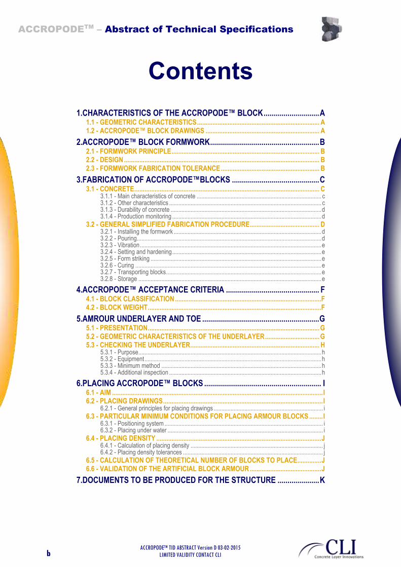
1.CHARACTERISTICS OF THE ACCROPODE™ BLOCK ............................ A 1.1 - GEOMETRIC CHARACTERISTICS ........................................................................ A 1.2 - ACCROPODE™ BLOCK DRAWINGS ................................................................... A
2.ACCROPODE™ BLOCK FORMWORK ....................................................... B 2.1 - FORMWORK PRINCIPLE ....................................................................................... B 2.2 - DESIGN ................................................................................................................... B 2.3 - FORMWORK FABRICATION TOLERANCE .......................................................... B
3.FABRICATION OF ACCROPODE™BLOCKS ............................................ C 3.1 - CONCRETE ............................................................................................................. C
3.1.1 - Main characteristics of concrete ................................................................................. c 3.1.2 - Other characteristics ................................................................................................... c 3.1.3 - Durability of concrete .................................................................................................. d 3.1.4 - Production monitoring ................................................................................................. d
3.2 - GENERAL SIMPLIFIED FABRICATION PROCEDURE ......................................... D 3.2.1 - Installing the formwork ................................................................................................ d 3.2.2 - Pouring ........................................................................................................................ d 3.2.3 - Vibration ...................................................................................................................... e 3.2.4 - Setting and hardening ................................................................................................. e 3.2.5 - Form striking ............................................................................................................... e 3.2.6 - Curing ......................................................................................................................... e 3.2.7 - Transporting blocks ..................................................................................................... e 3.2.8 - Storage ....................................................................................................................... e
4.ACCROPODE™ ACCEPTANCE CRITERIA ............................................... F 4.1 - BLOCK CLASSIFICATION ...................................................................................... F 4.2 - BLOCK WEIGHT ...................................................................................................... F
5.AMROUR UNDERLAYER AND TOE ........................................................... G 5.1 - PRESENTATION ..................................................................................................... G 5.2 - GEOMETRIC CHARACTERISTICS OF THE UNDERLAYER ................................ G 5.3 - CHECKING THE UNDERLAYER ............................................................................ H
5.3.1 - Purpose ....................................................................................................................... h 5.3.2 - Equipment ................................................................................................................... h 5.3.3 - Minimum method ........................................................................................................ h 5.3.4 - Additional inspection ................................................................................................... h
6.PLACING ACCROPODE™ BLOCKS ........................................................... I 6.1 - AIM ............................................................................................................................ I 6.2 - PLACING DRAWINGS .............................................................................................. I
6.2.1 - General principles for placing drawings ....................................................................... i 6.3 - PARTICULAR MINIMUM CONDITIONS FOR PLACING ARMOUR BLOCKS ........ I
6.3.1 - Positioning system ....................................................................................................... i 6.3.2 - Placing under water ..................................................................................................... i
6.4 - PLACING DENSITY ................................................................................................. J 6.4.1 - Calculation of placing density ...................................................................................... j 6.4.2 - Placing density tolerances ........................................................................................... j
6.5 - CALCULATION OF THEORETICAL NUMBER OF BLOCKS TO PLACE .............. J 6.6 - VALIDATION OF THE ARTIFICIAL BLOCK ARMOUR .......................................... J
7.DOCUMENTS TO BE PRODUCED FOR THE STRUCTURE ..................... K

ACCROPODETM
– Abstract of Technical Specifications
ACCROPODETM TID ABSTRACT Version D 03-02-2015
LIMITED VALIDITY CONTACT CLI
a
1. CHARACTERISTICS OF THE ACCROPODE™ BLOCK
1.1 - GEOMETRIC CHARACTERISTICS
The unit shape is defined and must be respected to ensure that the armour facing attains the necessary hydraulic stability performance. This document refers to the ACCROPODE™ unit developed in the early 1980s, this is named the first-generation ACCROPODE™ unit, as opposed to the second-generation ACCROPODE™ unit (called “ACCROPODE™ II) patented in 2000.
Volume V (m³) V = 0.34 H3 1 2 3 4 5 6 8 10 12 14 16 18 20 22 24 28
block Height H (m) H = (V/ 0.34)1/3 1.43 1.81 2.07 2.27 2.45 2.60 2.87 3.09 3.28 3.45 3.61 3.75 3.89 4.01 4.13 4.35
Armour thickness T (m) T = 0.9 H 1.29 1.63 1.86 2.05 2.21 2.34 2.58 2.78 2.95 3.11 3.25 3.38 3.50 3.61 3.72 3.92
Intermediate sizes are available on request.
GENERAL SHAPE OF THE ACCROPODE™ BLOCK
1.2 - ACCROPODE™ BLOCK DRAWINGS
The following drawings are supplied by CLI to the CONTRACTOR in accordance with the sub-licence (when it comes into effect) for preparing the formwork shop drawings.
The block shape must be scrupulously reproduced in order to guarantee the structural capability and stability of the ACCROPODE™ block.
Content of drawings
001 Shape definition drawing
002 Drawings of individual plates
003 Simplified formwork drawing (this is not a working drawing)
ACCROPODETM
– Abstract of Technical Specifications
ACCROPODETM TID ABSTRACT Version D 03-02-2015
LIMITED VALIDITY CONTACT CLI
b
2. ACCROPODE™ BLOCK FORMWORK
2.1 - FORMWORK PRINCIPLE
The formwork principle is shown in drawing no. 003, "Simplified formwork drawing".
The ACCROPODE™ formwork consists of two symmetrical, bottomless half-shells that can be separated. They are assembled to create a mould into which the concrete is poured.
The two half-shells are struck using a jack that presses on the end of the noses, thus detaching the form from the ACCROPODE™ block.
2.2 - DESIGN
The CONTRACTOR is responsible for designing the formwork and all ancillary parts. The design must comply with all standards in force. Safety devices such as access gangways must be sized in accordance with local legislation.
2.3 - FORMWORK FABRICATION TOLERANCE
All parts of the formwork must be welded together using a jig, the dimensions of which must be checked before any assembly takes place. The tolerances are as follows:
1. Jig: ±1mm
2. Dimensions of individual plates: ±1mm
3. Formwork assembly: dimensions of H (mm) = +/- [5mm + (H/1000)]
4. The volume of the block produced with the form must be at least equal to the theoretical volume

ACCROPODETM
– Abstract of Technical Specifications
ACCROPODETM TID ABSTRACT Version D 03-02-2015
LIMITED VALIDITY CONTACT CLI
c
3. FABRICATION OF ACCROPODE™BLOCKS
3.1 - CONCRETE
3.1.1 - Main characteristics of concrete
The present specifications are given in relation to standard EN NF 206-1
Criteria Specifications
Minimum 28-day strength for blocks ≤ 4m3 C25/30 (25 MPa on cylinder and 30 MPa on cube)
Minimum 28-day strength for blocks > 4m3 C30/37 (30 MPa on cylinder and 37 MPa on cube)
Exposure class (unless specified otherwise by the CLIENT)
XS3: Parts of marine structures, tidal range area subject to splashing
Minimum 28-day tensile strength – Blocks ≤ 4m3
Brazilian test / Fct,sp 2.5 Mpa
Minimum 28-day tensile strength – Blocks > 4m3
Brazilian test / Fct,sp 3.0 MPa
Minimum density As per designer's requirements
Maximum W/C ratio 0.45
Minimum equivalent binder content (cement + additives). To be adapted depending on size of aggregates. Cf. table EN NF 206.1 Tab NA F1
350 kg/m³
Maximum temperature of concrete on placing 30°C (indicative value)
Maximum hydration temperature (indicative only) 70°C (variable in relation to cement quality)
Aggregate quality EN NF 12620
Not frost-riven, alkali-reactive or aggressive for the other constituents of the concrete.
Aggregates may be crushed or rounded Category LA 35 or Micro Deval 25
Maximum diameter of aggregates (recommended size)
40 mm ≤ 6m³ and 60 mm > 6m³
Workability: consistency S2 to S4
Use of admixtures: authorised within the limits set in standard EN NF 934.2.
Use of cement additives authorised within the limits set in standard EN NF 206-1 annex NA F1.
Maximum aggregate diameter: see also Technical Information: Properties of Aggregates.
3.1.2 - Other characteristics
The compression values given below are those for cylinders. The following relation should be used to determine equivalent values for cubes:
Fck Cylinder =0.8 x Fck Cube (ref. BS 1881)
Blocks ≤ 4m3 Blocks between 5m
3 and 15m³ Blocks above 15m³
Minimum strength for form striking Fck Cyl 6 MPa 7 MPa 10 MPa
Minimum strength for handling Fck Cyl 15 Mpa 20 MPa 25 MPa
Minimum strength for placing Fck Cyl 25 MPa 30 MPa 30 MPa
Block weight
Weight at least equal to the weight taken into account in the studies or given by the designer of the structure.
Weight at least equal to the weight taken into account in the studies or given by the designer
of the structure.
Weight at least equal to the weight taken into account in the studies or given by the designer of the structure
ACCROPODETM
– Abstract of Technical Specifications
ACCROPODETM TID ABSTRACT Version D 03-02-2015
LIMITED VALIDITY CONTACT CLI
d
These values are given for general situations, and are to be used in all cases that do not call for any particular precautions. However, the CONTRACTOR may propose lower values if he can provide proof that they do not affect the structural integrity of the block.
3.1.3 - Durability of concrete
The durability of the materials to be used must be in accordance with the structure designer's stipulations. In addition, the CONTRACTOR must use materials that are compatible with the environment in which the blocks are to be used. Exposure class XS3 has been chosen as it takes into account aggression from the surrounding environment in which the armour blocks are to be used. Characteristics of the class XF4 will be taken into account in case of frost.
Furthermore, the CONTRACTOR must take special care in choosing the cement to be used and the quality of the aggregates. They must be compatible with the durability required by the structure's designer.
Recommendations are given in the Technical Information document.
3.1.4 - Production monitoring
The fabrication of ACCROPODE™ blocks shall be under the following frame of quality control:
Traceability of concrete composition and components.
Identification of blocks using a single number.
Appropriate concrete quality testing to ensure that production corresponds in every respect with the standards or specifications.
A concrete design mix test.
A trial mix test.
Concrete inspection tests.
The recommended tests and sampling procedures are those given in standard EN NF 206.1
3.2 - GENERAL SIMPLIFIED FABRICATION PROCEDURE
3.2.1 - Installing the formwork
The formwork must be installed in a stable, clean area. It must be oiled with a form striking agent enabling the block to be removed without damage.
The formwork must be positioned so that it is stable throughout the operations and perfectly watertight.
3.2.2 - Pouring
Concrete must be poured in layers of suitable thickness to ensure adequate compaction.
The concrete must not fall from a height of over 2 metres.

ACCROPODETM
– Abstract of Technical Specifications
ACCROPODETM TID ABSTRACT Version D 03-02-2015
LIMITED VALIDITY CONTACT CLI
e
3.2.3 - Vibration
Each layer of concrete must be vibrated to remove air bubbles and ensure adequate compaction. The degree and duration of vibration must be adapted to ensure that it fulfils its role, but special care must be taken to avoid any segregation of the concrete constituents.
3.2.4 - Setting and hardening
If weather conditions (temperature, wind, sun and rain) prevent the concrete from setting and hardening correctly, precautions must be taken to limit these effects.
3.2.5 - Form striking
Forms are struck when the concrete has reached the strength specified in section 3.1.2. Forms are struck by applying a force to the front protuberance with the jack. No tensile stress must be exerted on the block.
3.2.6 - Curing
Blocks must be cured after being removed from the forms, either with a chemical or with water (14 days in the case of water), to prevent the water from evaporating quickly.
3.2.7 - Transporting blocks
Blocks are to be transported when they have reached a structural strength at least equivalent to that given in section 3.1.2.
3.2.8 - Storage
Blocks are to be stored vertically or tilted. Blocks less than 6 m³ may be stored in two layers. The ground must be able to support the weight without any differential settlement or scouring that could destabilise the blocks.
ACCROPODETM
– Abstract of Technical Specifications
ACCROPODETM TID ABSTRACT Version D 03-02-2015
LIMITED VALIDITY CONTACT CLI
f
4. ACCROPODE™ UNITS ACCEPTANCE CRITERIA
4.1 - BLOCK CLASSIFICATION
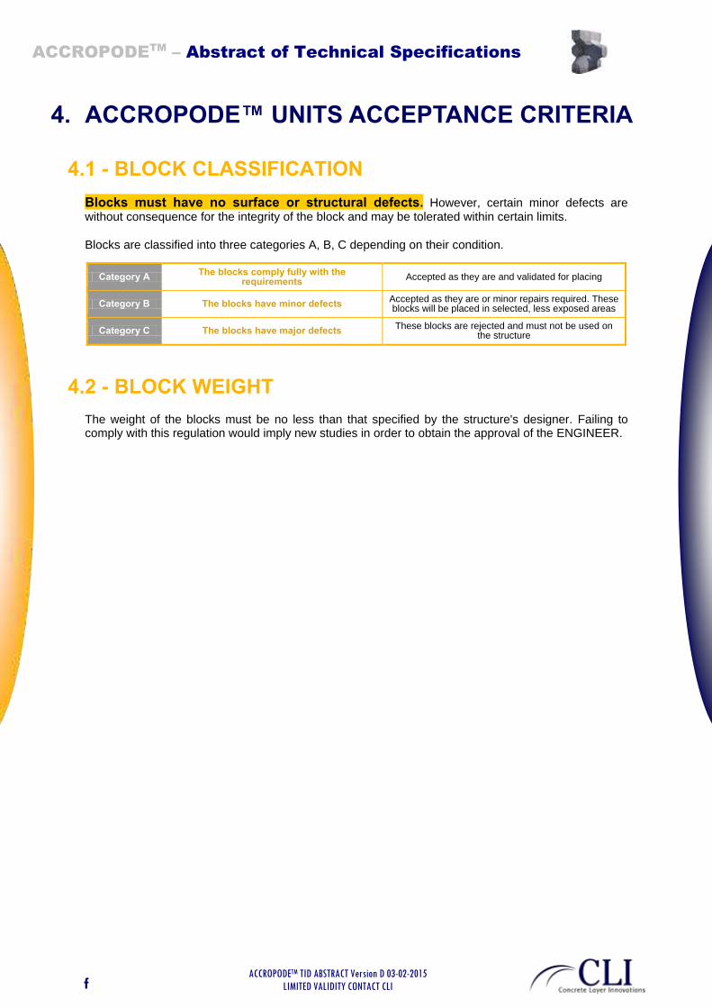
Blocks must have no surface or structural defects. However, certain minor defects are without consequence for the integrity of the block and may be tolerated within certain limits.
Blocks are classified into three categories A, B, C depending on their condition.
Category A The blocks comply fully with the
requirements Accepted as they are and validated for placing
Category B The blocks have minor defects Accepted as they are or minor repairs required. These blocks will be placed in selected, less exposed areas
Category C The blocks have major defects These blocks are rejected and must not be used on
the structure
4.2 - BLOCK WEIGHT
The weight of the blocks must be no less than that specified by the structure's designer. Failing to comply with this regulation would imply new studies in order to obtain the approval of the ENGINEER.
ACCROPODETM
– Abstract of Technical Specifications
ACCROPODETM TID ABSTRACT Version D 03-02-2015
LIMITED VALIDITY CONTACT CLI
g
5. AMROUR UNDERLAYER AND TOE
5.1 - PRESENTATION
The underlayer of the concrete armour consists of natural rockfill but other materials such as shattered concrete may be included when the structure's designer has clearly specified this.
The size and characteristics of the underlayer rockfill are defined by structure's designer. However the following principles are recalled to ensure that the underlayer is suited to the armour:
Rocks must be sufficiently large to prevent them from escaping through the armour. If they should have large flat surfaces they must not create any slip plane. Underlayer placing tolerances must be observed regardless of the size of the rocks used.
5.2 - GEOMETRIC CHARACTERISTICS OF THE UNDERLAYER
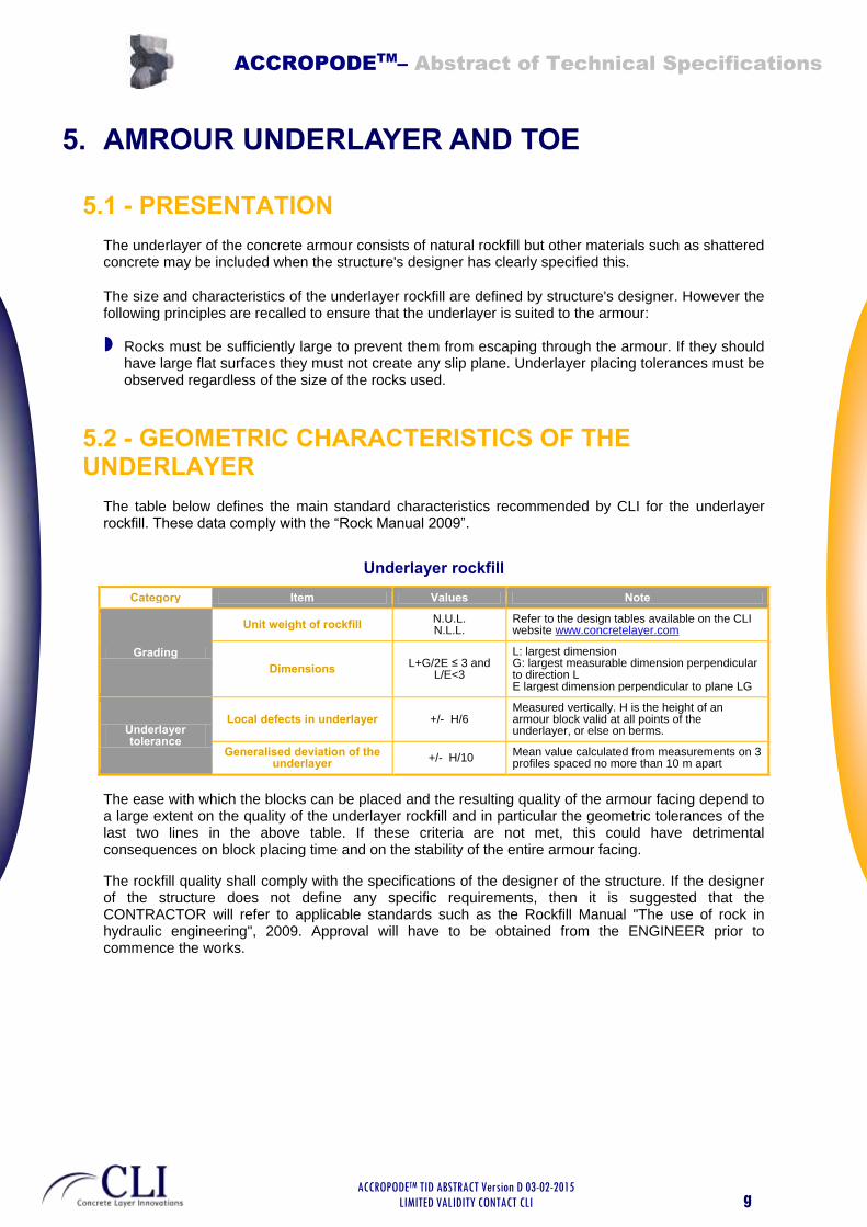
The table below defines the main standard characteristics recommended by CLI for the underlayer rockfill. These data comply with the “Rock Manual 2009”.
Underlayer rockfill
Category Item Values Note
Grading
Unit weight of rockfill N.U.L. N.L.L.
Refer to the design tables available on the CLI website www.concretelayer.com
Dimensions L+G/2E ≤ 3 and
L/E<3
L: largest dimension G: largest measurable dimension perpendicular to direction L E largest dimension perpendicular to plane LG
Underlayer tolerance
Local defects in underlayer +/- H/6 Measured vertically. H is the height of an armour block valid at all points of the underlayer, or else on berms.
Generalised deviation of the underlayer
+/- H/10 Mean value calculated from measurements on 3 profiles spaced no more than 10 m apart
The ease with which the blocks can be placed and the resulting quality of the armour facing depend to a large extent on the quality of the underlayer rockfill and in particular the geometric tolerances of the last two lines in the above table. If these criteria are not met, this could have detrimental consequences on block placing time and on the stability of the entire armour facing.
The rockfill quality shall comply with the specifications of the designer of the structure. If the designer of the structure does not define any specific requirements, then it is suggested that the CONTRACTOR will refer to applicable standards such as the Rockfill Manual "The use of rock in hydraulic engineering", 2009. Approval will have to be obtained from the ENGINEER prior to commence the works.
ACCROPODETM
– Abstract of Technical Specifications
ACCROPODETM TID ABSTRACT Version D 03-02-2015
LIMITED VALIDITY CONTACT CLI
h
5.3 - CHECKING THE UNDERLAYER
5.3.1 - Purpose
The underlayer must be suitable for placing the armour blocks. The underlayer must comply in every respect with the tolerances defined in section 5.2 and must be stable during placing. Rockfill must not be able to become detached from the underlayer when the armour blocks are being placed.
5.3.2 - Equipment
The CONTRACTOR is free to choose the type of equipment to be used for measuring the underlayer.
It may be mechanical (soundings along the underlayer) or electronic (single- or multi-beam sonars).
5.3.3 - Minimum method
1 profile every 10m along the breakwater. This minimum may be lowered to 5 m in complex areas.
Each profile will involve at least one sounding every H m (H = block height) along the slope, taking care to investigate precisely the foot of the underlayer, the horizontal berm and the crest of the underlayer, The berm at the foot of the structure is measured over a minimum distance of 2H from the angle formed by the slope and flat part of the structure.
The fact that the profile surveys can be spaced up to 10 m apart does not alter the requirement that the tolerance must be observed at all points of the underlayer.
The CONTRACTOR must take all necessary measures to ensure that this tolerance is observed between profiles. If necessary the profiles can be surveyed much closer together.
5.3.4 - Additional inspection
The underlayer must be inspected visually both above and under water to ensure that it is compatible with placing the armour blocks.
Armour block placing must not begin under any circumstances until the underlayer has been validated by the ENGINEER.
ACCROPODETM
– Abstract of Technical Specifications
ACCROPODETM TID ABSTRACT Version D 03-02-2015
LIMITED VALIDITY CONTACT CLI
i
6. PLACING ACCROPODE™ BLOCKS
6.1 - AIM
The aim of placing work is to obtain a stable armouring that complies with the fundamental principles of the ACCROPODE ™ technique:
Placing density within the limits set out in section 6.4.
Blocks are in a single layer and no block must be out of profile (less than 1/3 of the block outside the armour). Each block is in contact with the underlayer.
Blocks are interlocked with one another and not free to move.
The lozenge-shaped grid is used everywhere. Local exceptions are tolerated.
The underlayer rock fill cannot escape if there are any gaps between blocks.
Blocks are placed in mostly varied attitudes.
6.2 - PLACING DRAWINGS
6.2.1 - General principles for placing drawings
Theoretical placing drawings for the armour blocks are supplied by CLI. Placing drawings are prepared by CLI on the basis of construction drawings provided by the CONTRACTOR. These may be as-built drawings of the underlayer, or theoretical working drawings of the structure. The placing drawings give the theoretical x and y coordinates of the centre of gravity of each block to be placed. They are based on a grid principle that defines a compulsory placing density.
The drawings may also indicate a z coordinate when a positioning system requiring a third dimension is used. The placing drawing provides a reference placing density to check the actual placing density achieved, which is vital for the stability of the armour.
6.3 - PARTICULAR MINIMUM CONDITIONS FOR PLACING ARMOUR BLOCKS
6.3.1 - Positioning system
ACCROPODE™ blocks are to be placed using equipment that can place them both above and under water in accordance with the coordinates provided by CLI with the placing drawings. The equipment may be mechanical or electronic of the DGPS type, an underwater positioner or POSIBLOC™ placing assistance system. Accuracy measured in a stable condition at the block release hook must be at least H/12The system must also record the final position of the block to within H/12 of accuracy (this is not a tolerance from the target, this is the accuracy of the system).. It must be possible to export the points recorded to an AutoCAD file in order to calculate the density with reference to the placing drawings.
Block placing by sight is authorised above water, but is essential to record the real coordinates of the blocks.
6.3.2 - Placing under water
As the blocks must be interlocked, it is essential for underwater placing to be assisted and checked, either by an underwater viewing system or by diving supervisors. The supervisors must ensure that

ACCROPODETM
– Abstract of Technical Specifications
ACCROPODETM TID ABSTRACT Version D 03-02-2015
LIMITED VALIDITY CONTACT CLI
j
the blocks are perfectly interlocked and that the placing rules have been observed. Divers must be used only immediately after placement of each blocks underwater, and strict compliance with safety regulations is essential.
6.4 - PLACING DENSITY
Placing density is an important factor for the stability of the armour. Placing density varies depending on the interlocking of the blocks on site. Regular calculations must be performed to check the placing density and ensure that is kept within acceptable proportions.
6.4.1 - Calculation of placing density
The placing density is calculated area by area, but measurements must be performed in all parts of the breakwater. A density calculation must also be performed for the upper berm.
6.4.2 - Placing density tolerances
For the side slope: the actual placing density must be between 95% and 105% of that shown on the theoretical placing drawing.
For the berm: the actual placing density must be between 95% and 105% of the theoretical number of blocks per 100 m² given by CLI.
6.5 - CALCULATION OF THEORETICAL NUMBER OF BLOCKS TO PLACE
The CONTRACTOR is responsible for calculating the final number of blocks to fabricate and place on the structure.
At the beginning of work on site, the CONTRACTOR must make a precise estimation of the number of blocks needed for the structure. This estimation involves a theoretical calculation based on the number of blocks per 100 m² indicated by CLI (refer to CLI web site with the “design tables” ) and the area to be covered.
6.6 - VALIDATION OF THE ARTIFICIAL BLOCK ARMOUR
The artificial block armour shall be inspected by the CLIENT or his representative (ENGINEER) with a view to performing acceptance procedures and the CONTRACTOR shall allow enough time for this operation. The inspection will focus on the points referred to in section 6.1, which defines the armour acceptance criteria.
For the inspection to go smoothly, the CONTRACTOR shall forward the Technical Specifications to the CLIENT and ENGINEER. The CLIENT and / or the ENGINEER may instruct the CONTRACTOR to organise a training session by a CLI specialist for the ACCROPODE™ armour layer works approval. CLI is not in charge of approving the works.
Inspections should be performed as work progresses.

ACCROPODETM
– Abstract of Technical Specifications
ACCROPODETM TID ABSTRACT Version D 03-02-2015
LIMITED VALIDITY CONTACT CLI
k
7. DOCUMENTS TO BE PRODUCED FOR THE STRUCTURE
The CONTRACTOR using the technique must introduce a system for monitoring the quality of placing on the structure.
Documents handed to CLI are for information purposes only and CLI may express its technical opinion on them. The documents to be handed over to the ENGINEER or CLIENT are those for monitoring works implementation.
The CONTRACTOR is left to choose the monitoring system, but the following documents at least must be produced:
DOCUMENTS TO PRODUCE ENGINEER/CLIENT
For approval CLI
For information
Theoretical drawings of the structure (plan view/typical sections)
At least 3 weeks before starting
works
Detailed block fabrication procedure Before starting fabrication Before starting fabrication
Inspection of form dimensions Before starting fabrication Production of forms
Concrete design mix documents Before producing blocks Before producing blocks
Concrete trial mix documents Before industrial block
production Before industrial block
production
Traceability sheet for each block During block production First month of fabrication
Block weights During block production First month of fabrication
Concrete inspection/traceability records During block production First month of fabrication
Detailed procedure for placing the underlayer and armour blocks
Before start of block placing Before start of block placing
Profiles of the underlayer every 5m or 10 m Underlayer inspection report
Throughout works First month of placing
Photographs of the underlayer Throughout works First 100 metres
Block placing monitoring sheet Throughout works First 50 blocks
As-built drawings of block placing (AutoCAD format) Throughout works End of works
Density calculations area by area over the entire structure As placing progresses First month of placing
Periodic survey of settlement reference points End of works unless anomaly
observed If anomaly observed
Photos or videos of placing both under and above water Throughout works First month and particular
areas
POSIBLOC™ files (if used) Throughout works First month
Monthly block placing "Progress report". Monthly, before 5th of month


