59
AccuCell Technical Training AccuCell Commands & Concepts
AccuCell Technical Training
AccuCell Commands & Concepts
AccuCell Commands and Concepts
Agenda
Introduction to AccuCell and AccuCore Cell Characterization Introduction to AccuCell Getting Started with Accucell Methods of Characterization Sequential Cells Power Characterization
- 2 -

AccuCell Commands and Concepts
Silvaco Characterization Flow
- 3 -
AccuTools Timing Power Function
Cell Block Core
Timing
Timing Power Function
Functional Extraction
Vector Generation
Dynamic Simulation
Model Generation
Block/Core Partitioning Characterization Static
Timing Model Generation
Model Generation
Cell
Block/Core
AccuCell Commands and Concepts
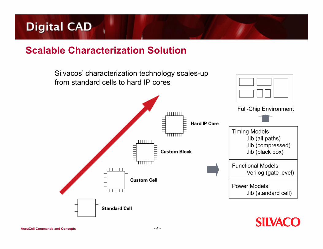
Scalable Characterization Solution
- 4 -
Silvacos’ characterization technology scales-up from standard cells to hard IP cores
Full-Chip Environment
Timing Models .lib (all paths) .lib (compressed) .lib (black box)
Functional Models Verilog (gate level)
Power Models .lib (standard cell)

AccuCell Commands and Concepts
Agenda
Introduction to AccuCell and AccuCore Cell Characterization Introduction to AccuCell Getting Started with AccuCell Methods of Characterization Sequential Cells Power Characterization
- 5 -
AccuCell Commands and Concepts
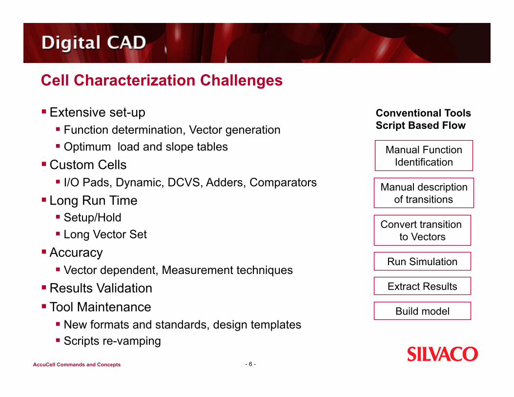
Cell Characterization Challenges
Extensive set-up Function determination, Vector generation Optimum load and slope tables
Custom Cells I/O Pads, Dynamic, DCVS, Adders, Comparators
Long Run Time Setup/Hold Long Vector Set
Accuracy Vector dependent, Measurement techniques
Results Validation Tool Maintenance
New formats and standards, design templates Scripts re-vamping
- 6 -
Conventional Tools Script Based Flow
Manual Function Identification
Manual description of transitions
Convert transition to Vectors
Run Simulation
Extract Results
Build model
AccuCell Commands and Concepts
Agenda
Introduction to AccuCell and AccuCore Cell Characterization Introduction to AccuCell Getting Started with Accucell Methods of Characterization Sequential Cells Power Characterization
- 7 -
AccuCell Commands and Concepts
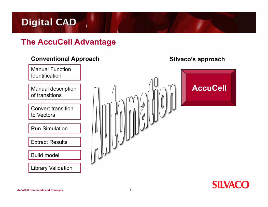
The AccuCell Advantage
- 8 -
Conventional Approach
Manual description of transitions
Convert transition to Vectors
Run Simulation
Manual Function Identification
Extract Results
Build model
Library Validation
Silvaco’s approach
AccuCell
AccuCell Commands and Concepts
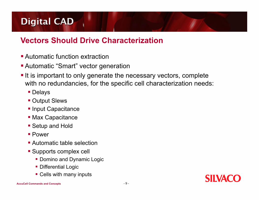
Vectors Should Drive Characterization
Automatic function extraction Automatic “Smart” vector generation It is important to only generate the necessary vectors, complete
with no redundancies, for the specific cell characterization needs: Delays Output Slews Input Capacitance Max Capacitance Setup and Hold Power Automatic table selection Supports complex cell
Domino and Dynamic Logic Differential Logic Cells with many inputs
- 9 -
AccuCell Commands and Concepts
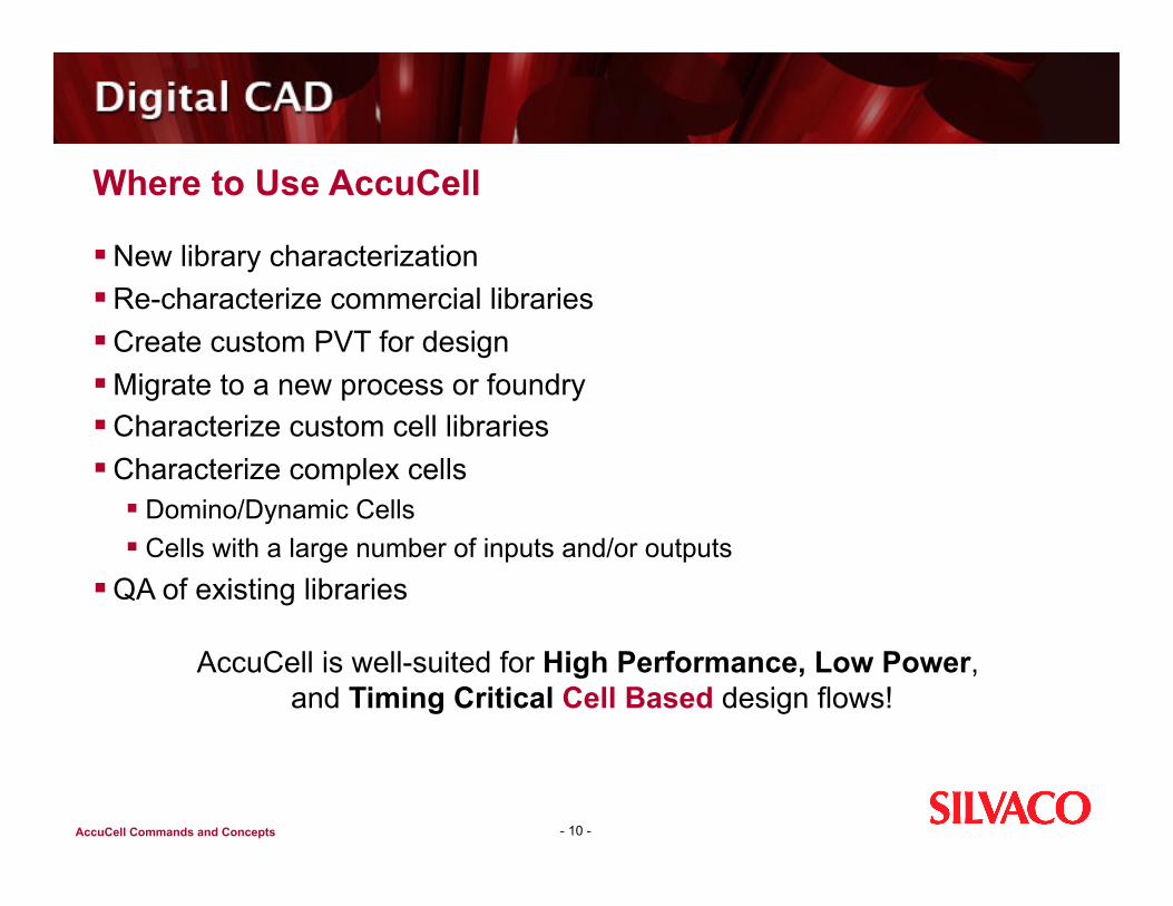
Where to Use AccuCell
New library characterization Re-characterize commercial libraries Create custom PVT for design Migrate to a new process or foundry Characterize custom cell libraries Characterize complex cells
Domino/Dynamic Cells Cells with a large number of inputs and/or outputs
QA of existing libraries
- 10 -
AccuCell is well-suited for High Performance, Low Power, and Timing Critical Cell Based design flows!
AccuCell Commands and Concepts
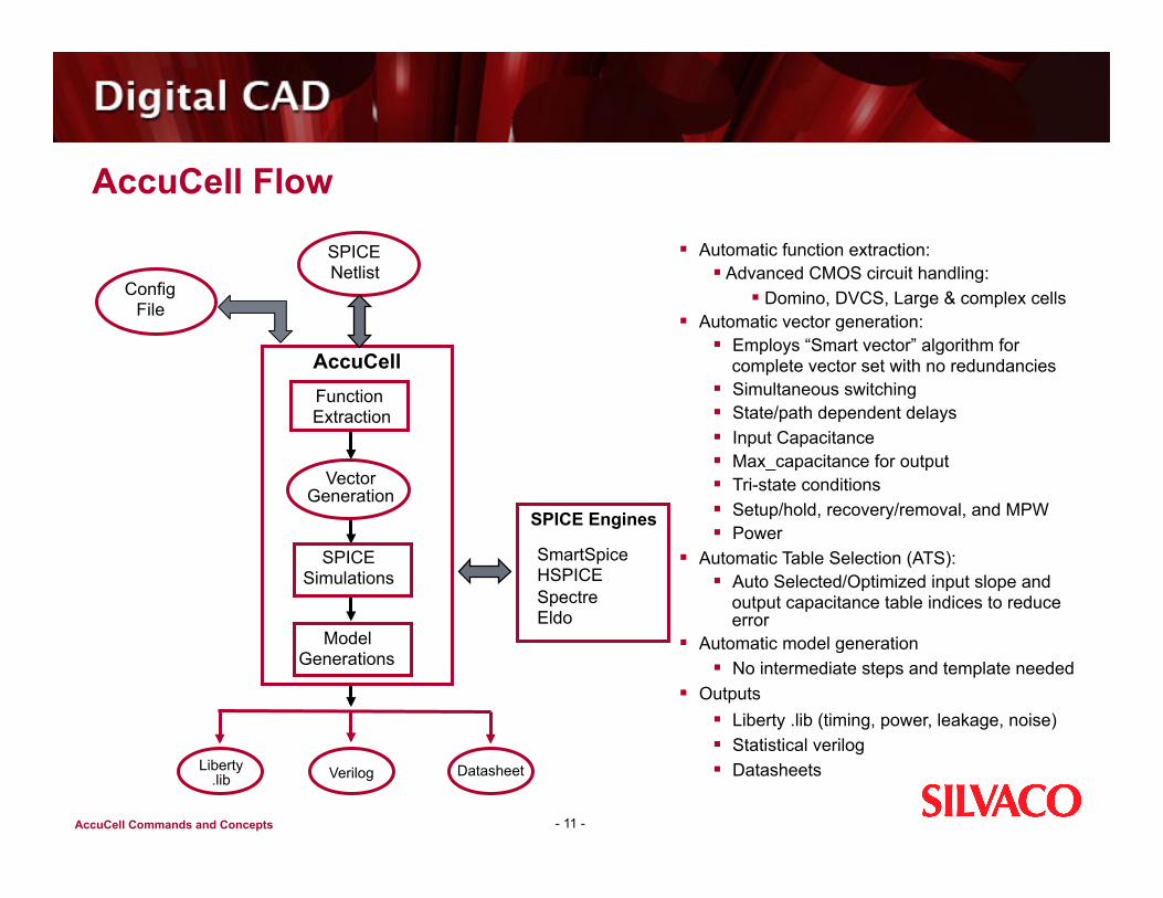
AccuCell Flow
- 11 -
AccuCell Function Extraction
Vector Generation
SPICE Simulations
Config File
SPICE Netlist
Liberty .lib Verilog Datasheet
Model Generations
SPICE Engines
SmartSpice HSPICE Spectre Eldo
Automatic function extraction: Advanced CMOS circuit handling:
Domino, DVCS, Large & complex cells Automatic vector generation:
Employs “Smart vector” algorithm for complete vector set with no redundancies
Simultaneous switching State/path dependent delays Input Capacitance Max_capacitance for output Tri-state conditions Setup/hold, recovery/removal, and MPW Power
Automatic Table Selection (ATS): Auto Selected/Optimized input slope and
output capacitance table indices to reduce error
Automatic model generation No intermediate steps and template needed
Outputs Liberty .lib (timing, power, leakage, noise) Statistical verilog Datasheets
AccuCell Commands and Concepts
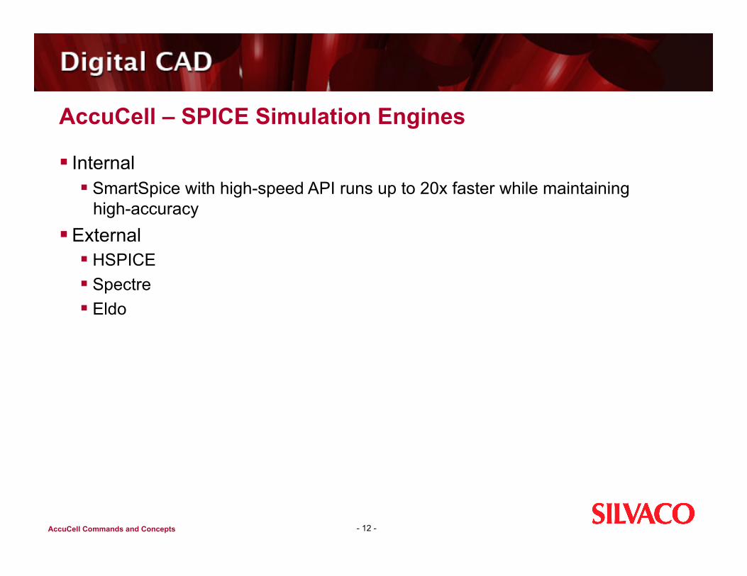
AccuCell – SPICE Simulation Engines
Internal SmartSpice with high-speed API runs up to 20x faster while maintaining
high-accuracy External
HSPICE Spectre Eldo
- 12 -

AccuCell Commands and Concepts
Agenda
Introduction to AccuCell and AccuCore Cell Characterization Introduction to AccuCell Getting Started with AccuCell Methods of Characterization Sequential Cells Power Characterization
- 13 -

AccuCell Commands and Concepts
LAB 1 Objectives
Purpose: To become familiar with setting up cfg files and running AccuCell.
Setup a AccuCell run Run AccuCell to characterize a single cell Run AccuCell to characterize a cell library Familiarize yourself with the output formats of AccuCell
- 14 -
AccuCell Commands and Concepts
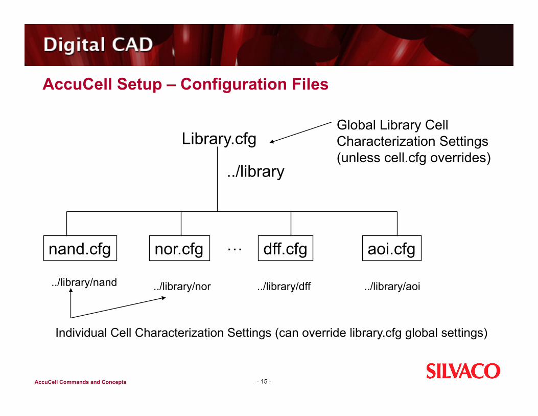
AccuCell Setup – Configuration Files
- 15 -
Library.cfg Global Library Cell Characterization Settings (unless cell.cfg overrides)
../library
nand.cfg nor.cfg … dff.cfg aoi.cfg
../library/nand ../library/nor ../library/dff ../library/aoi
Individual Cell Characterization Settings (can override library.cfg global settings)
AccuCell Commands and Concepts
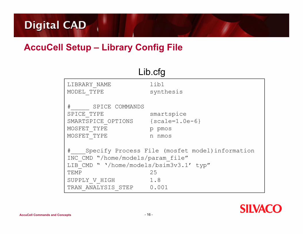
AccuCell Setup – Library Config File
- 16 -
Lib.cfg LIBRARY_NAME lib1 MODEL_TYPE synthesis
#_____ SPICE COMMANDS SPICE_TYPE smartspice SMARTSPICE_OPTIONS {scale=1.0e-6} MOSFET_TYPE p pmos MOSFET_TYPE n nmos
#____Specify Process File (mosfet model)information INC_CMD “/home/models/param_file” LIB_CMD “ ‘/home/models/bsim3v3.1’ typ” TEMP 25 SUPPLY_V_HIGH 1.8 TRAN_ANALYSIS_STEP 0.001
AccuCell Commands and Concepts
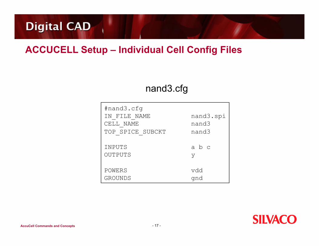
ACCUCELL Setup – Individual Cell Config Files
- 17 -
nand3.cfg
#nand3.cfg IN_FILE_NAME nand3.spi CELL_NAME nand3 TOP_SPICE_SUBCKT nand3
INPUTS a b c OUTPUTS y
POWERS vdd GROUNDS gnd
AccuCell Commands and Concepts
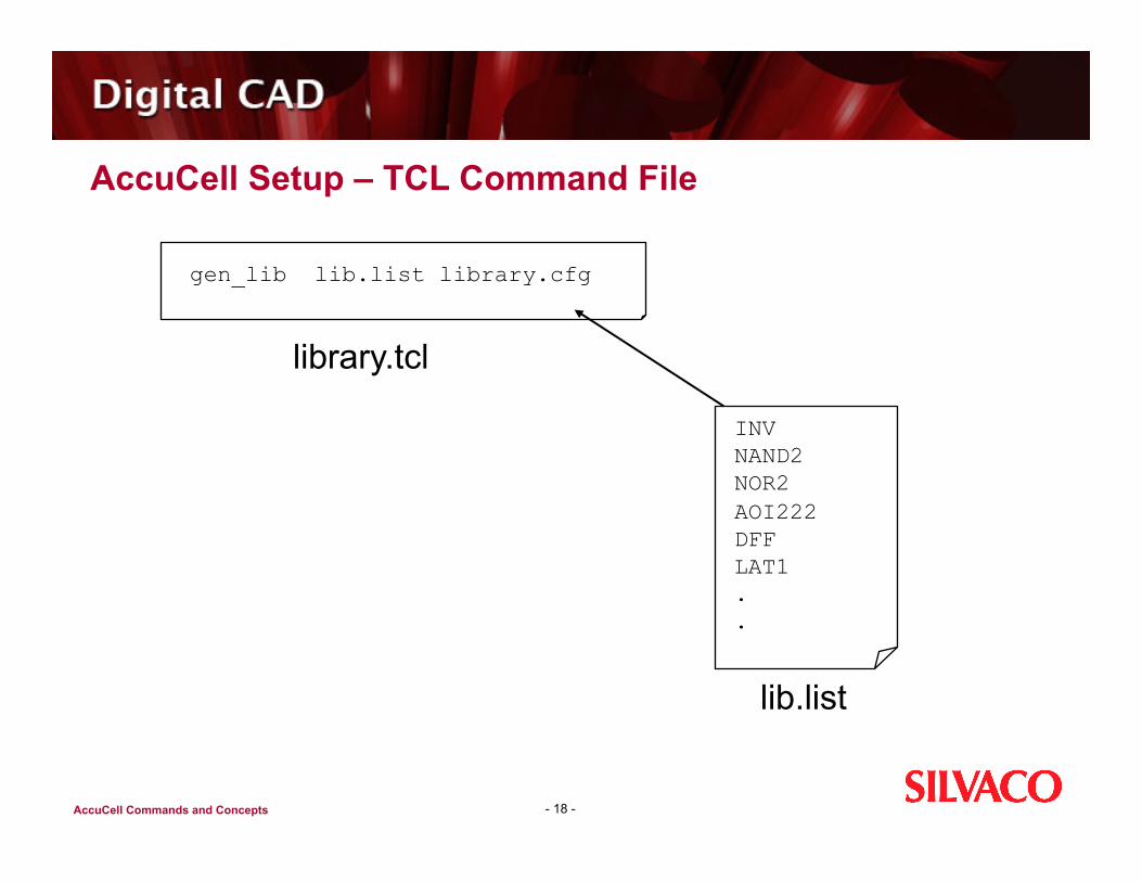
AccuCell Setup – TCL Command File
- 18 -
library.tcl
lib.list
gen_lib lib.list library.cfg
INV NAND2 NOR2 AOI222 DFF LAT1 . .

AccuCell Commands and Concepts
Running AccuCell
- 19 -
unix% accucell library.tcl | & tee log
gen_lib lib.list library.cfg
AccuCell Commands and Concepts
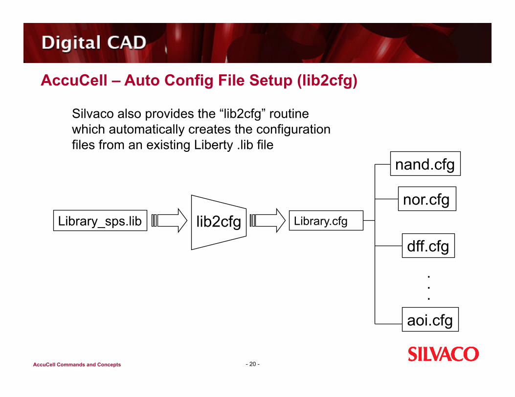
AccuCell – Auto Config File Setup (lib2cfg)
- 20 -
Silvaco also provides the “lib2cfg” routine which automatically creates the configuration files from an existing Liberty .lib file
nand.cfg
nor.cfg
dff.cfg
.
.
.aoi.cfg
Library_sps.lib lib2cfg Library.cfg

AccuCell Commands and Concepts
Agenda
Introduction to Silvaco Cell Characterization Introduction to AccuCell Getting Started with Accucell Methods of Characterization Sequential Cells Power Characterization
- 21 -
AccuCell Commands and Concepts
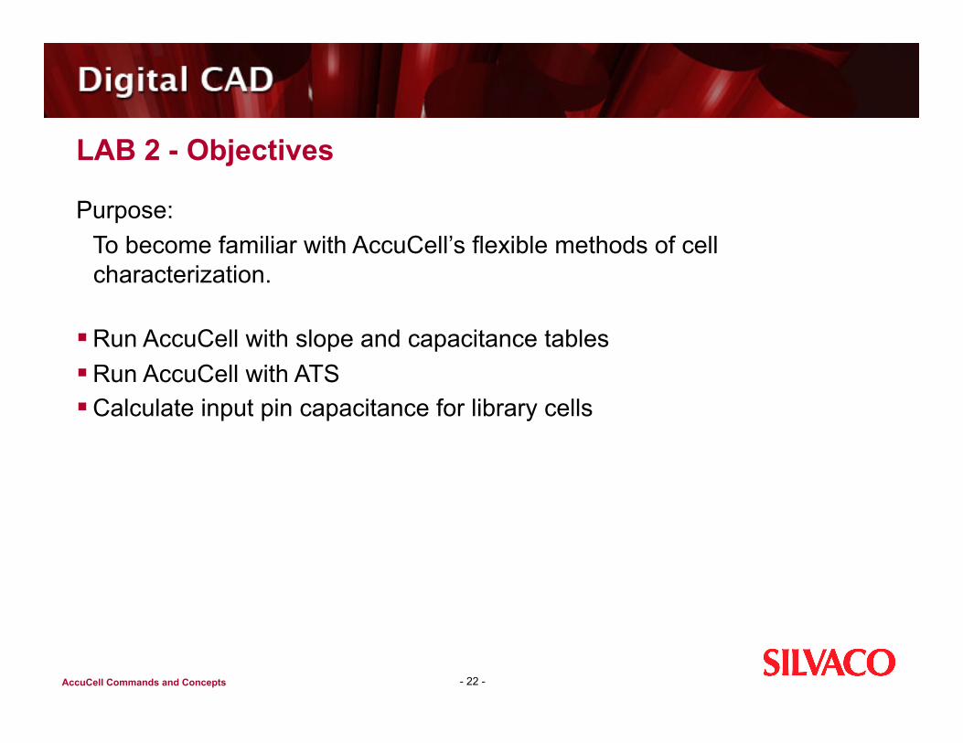
LAB 2 - Objectives
Purpose: To become familiar with AccuCell’s flexible methods of cell
characterization.
Run AccuCell with slope and capacitance tables Run AccuCell with ATS Calculate input pin capacitance for library cells
- 22 -
AccuCell Commands and Concepts
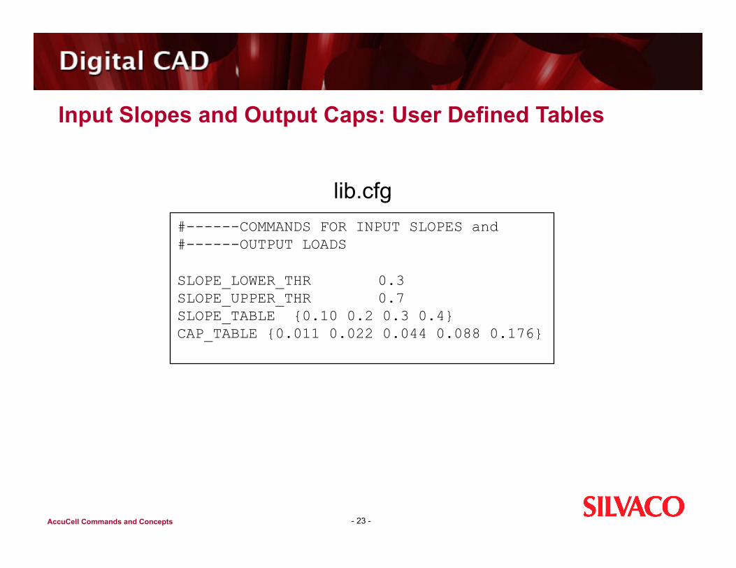
Input Slopes and Output Caps: User Defined Tables
- 23 -
lib.cfg #------COMMANDS FOR INPUT SLOPES and #------OUTPUT LOADS
SLOPE_LOWER_THR 0.3 SLOPE_UPPER_THR 0.7 SLOPE_TABLE {0.10 0.2 0.3 0.4} CAP_TABLE {0.011 0.022 0.044 0.088 0.176}
AccuCell Commands and Concepts
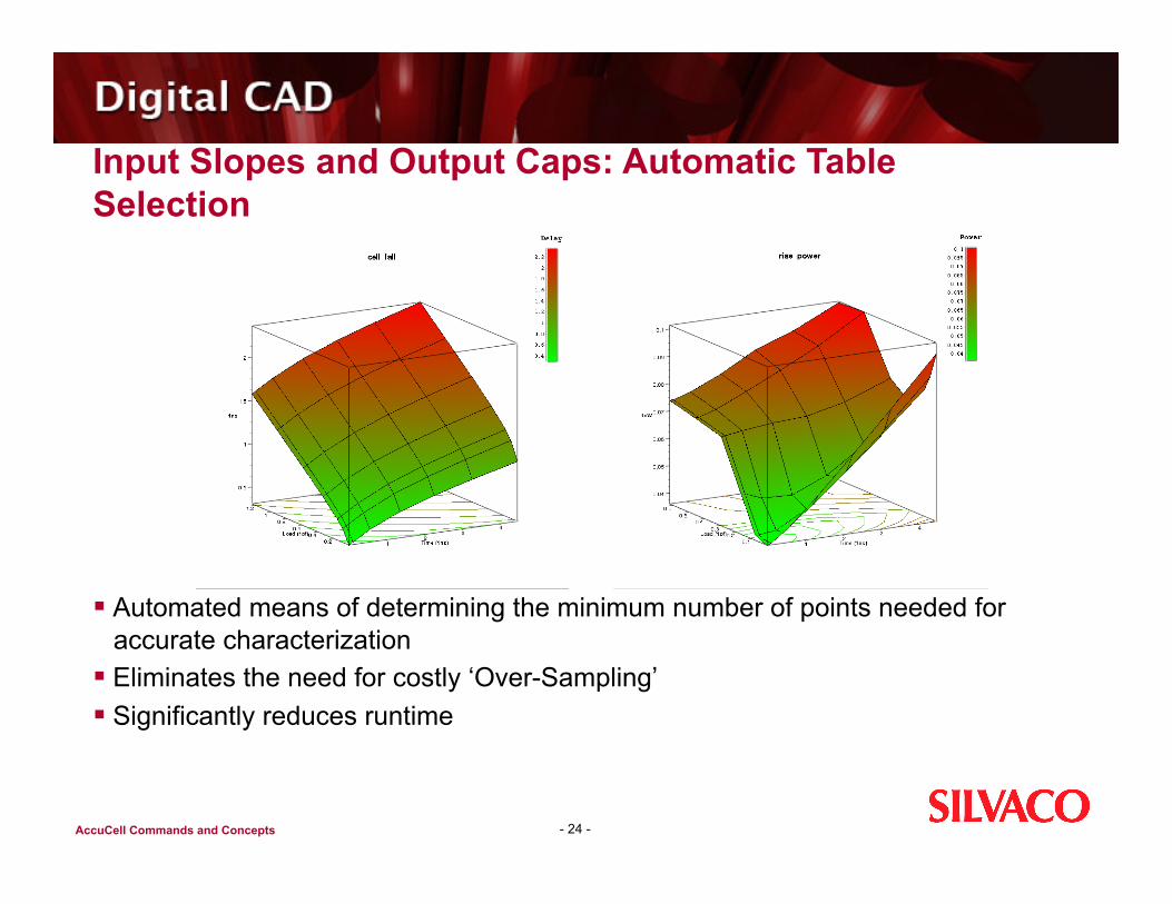
Input Slopes and Output Caps: Automatic Table Selection
Automated means of determining the minimum number of points needed for accurate characterization
Eliminates the need for costly ‘Over-Sampling’ Significantly reduces runtime
- 24 -
AccuCell Commands and Concepts
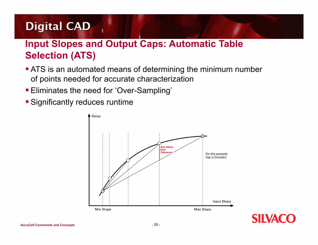
Input Slopes and Output Caps: Automatic Table Selection (ATS) ATS is an automated means of determining the minimum number
of points needed for accurate characterization Eliminates the need for ‘Over-Sampling’ Significantly reduces runtime
- 25 -
AccuCell Commands and Concepts
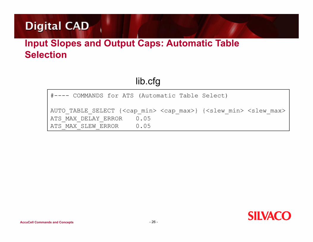
Input Slopes and Output Caps: Automatic Table Selection
- 26 -
lib.cfg #---- COMMANDS for ATS (Automatic Table Select)
AUTO_TABLE_SELECT {<cap_min> <cap_max>} {<slew_min> <slew_max> ATS_MAX_DELAY_ERROR 0.05 ATS_MAX_SLEW_ERROR 0.05

AccuCell Commands and Concepts
Input Pin Cap – Integrate Method
- 27 -
Technique includes finding the Cin got both the rising and failing output conditions then AVERAGING the two for the final input capacitance (CIN) for the input pin.
CALC_C_EFF 1 C_EFF_RISE_SLOPE 0.05 C_EFF_FALL_SLOPE 0.05 CUR_MEAS_PERIOD 1.0
AccuCell Commands and Concepts
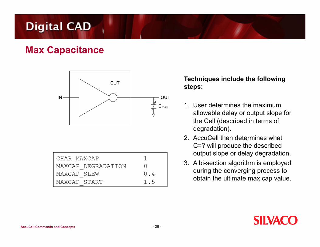
Max Capacitance
- 28 -
CHAR_MAXCAP 1 MAXCAP_DEGRADATION 0 MAXCAP_SLEW 0.4 MAXCAP_START 1.5
Techniques include the following steps:
1. User determines the maximum allowable delay or output slope for the Cell (described in terms of degradation).
2. AccuCell then determines what C=? will produce the described output slope or delay degradation.
3. A bi-section algorithm is employed during the converging process to obtain the ultimate max cap value.

AccuCell Commands and Concepts
Data Sheets
- 29 -
Data Sheets generated by AccuCell enhances usability and readability of the characterization data

AccuCell Commands and Concepts
Agenda
Introduction to Silvaco Cell Characterization Introduction to AccuCell Getting Started with Accucell Methods of Characterization Sequential Cells Power Characterization
- 30 -
AccuCell Commands and Concepts
LAB 3 – Objectives
To become familiar characterizing Sequential cells using AccuCell
Setup an equation file (*.eqn) Setup AccuCell for Setup/Hold Characterization. Run AccuCell on a sequential cell
- 31 -
AccuCell Commands and Concepts
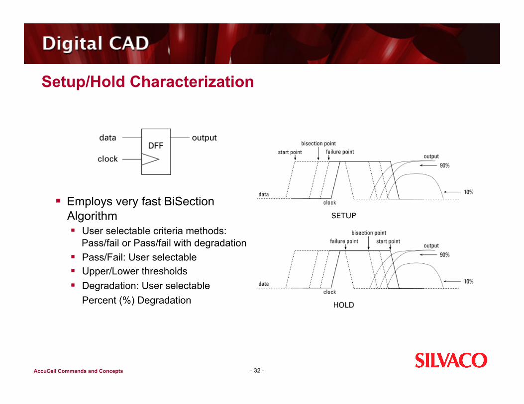
Setup/Hold Characterization
- 32 -
Employs very fast BiSection Algorithm User selectable criteria methods:
Pass/fail or Pass/fail with degradation Pass/Fail: User selectable Upper/Lower thresholds Degradation: User selectable Percent (%) Degradation
AccuCell Commands and Concepts
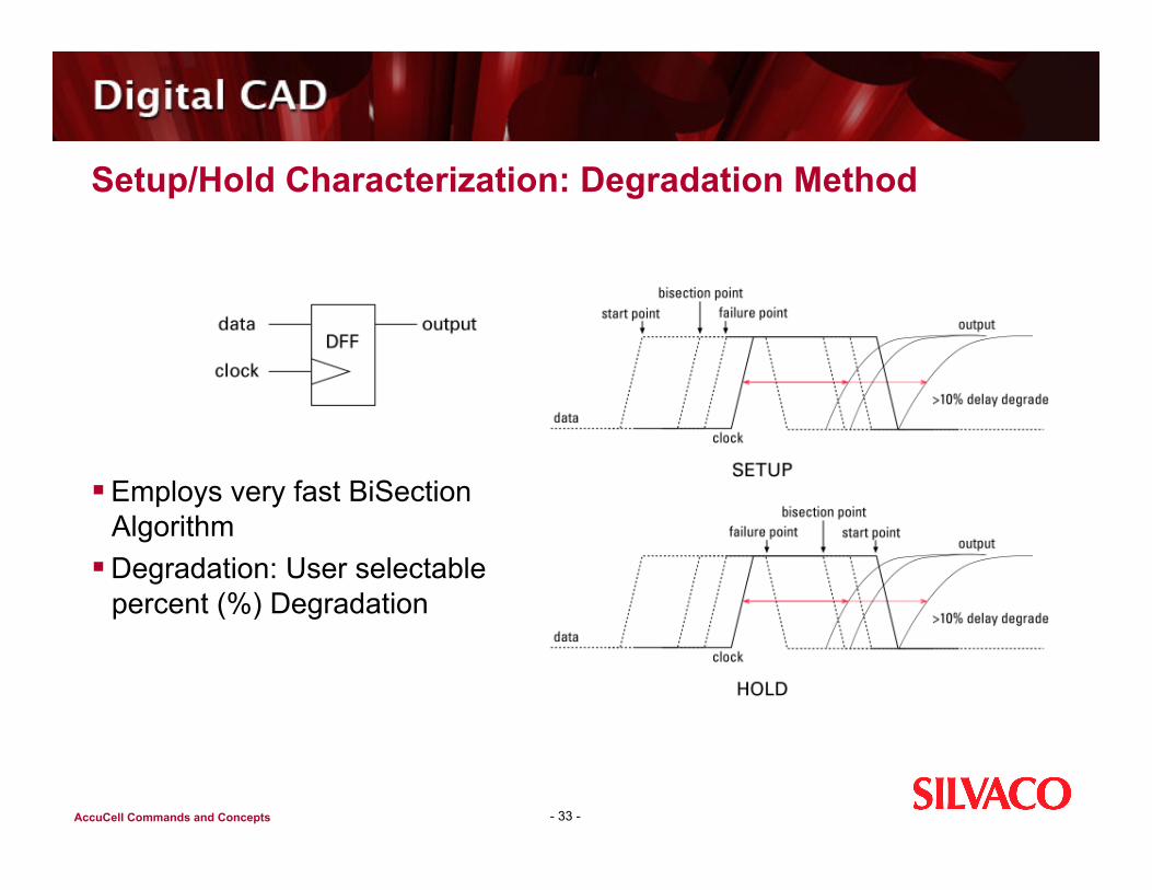
Setup/Hold Characterization: Degradation Method
Employs very fast BiSection Algorithm
Degradation: User selectable percent (%) Degradation
- 33 -

AccuCell Commands and Concepts
AccuCell Commands for SETUP/HOLD
- 34 -
#--------COMMANDS for SETUP & HOLD
SETHLD_2D 1 SH_DATA_SLOPE_TABLE {0.1 0.2 0.3 0.4} SH_CLK_SLOPE_TABLE {0.05 0.1 0.5 1.0}
# for Delay Degradation (15% degradation) SETHOLD_DELAY 0.15
lib.cfg

AccuCell Commands and Concepts
What does Single_Simulation do?
SINGLE_SIMULATION 1 Reduce run time significantly if a table is needed for setup/hold AccuCell puts .data statement in the spice deck to do single simulation
for setup/hold instead of multiple simulations For external simulators only
- 35 -

AccuCell Commands and Concepts
User Defined Equations and Explicit Tables
- 36 -
dff.cfg IN_FILE_NAME dff.spi CELL_NAME dff TOP_SPICE_SUBCKT dff #EQN_FILE_NAME dff.eqn #TBL_FILE_NAME dff.tbl
CLOCKS main ck INPUTS d nr ns OUTPUTS nq q
POWERS vdd GROUNDS gnd
dff.eqn q.0:= ~d & nr & ns & main- | ~nr & ns; q.1:= d & nr & ns & main- | nr & ns; nq.0:=, d & nr & ns & main- | nr & ns; nq.0:= ~d & nr & ns & main- | ~nr & ns;
dff.tbl Please refer to the explict table in the tutorial or Users Guide for more details.
Note: Equations and/or table files are rarely necessary and typically only used for complex cells. It is NOT necessarily required for flip-flop or latches. Use either .eqn or .tbl method but NOT both at the same time in the .cfg file.

AccuCell Commands and Concepts
Recovery and Removal
- 37 -
AccuCell Config Command: CHAR_RECREM <0 or 1> Where 1 requires AccuCell to run recovery and removal calculations. The default is 0
AccuCell Operation AccuCell generates a table for recovery and removal values. The table indices are the same as those for synchronous pin setup and hold value. That is, they are also defined by the following two configuration commands:
SH_DATA_SLOPE_TABLE {……..} SH_CLK_SLOPE_TABLE {……..}
Just like for setup and hold measurements, AccuCell also employs bi-section method to perform the recovery and removal measurements.
AccuCell Commands and Concepts
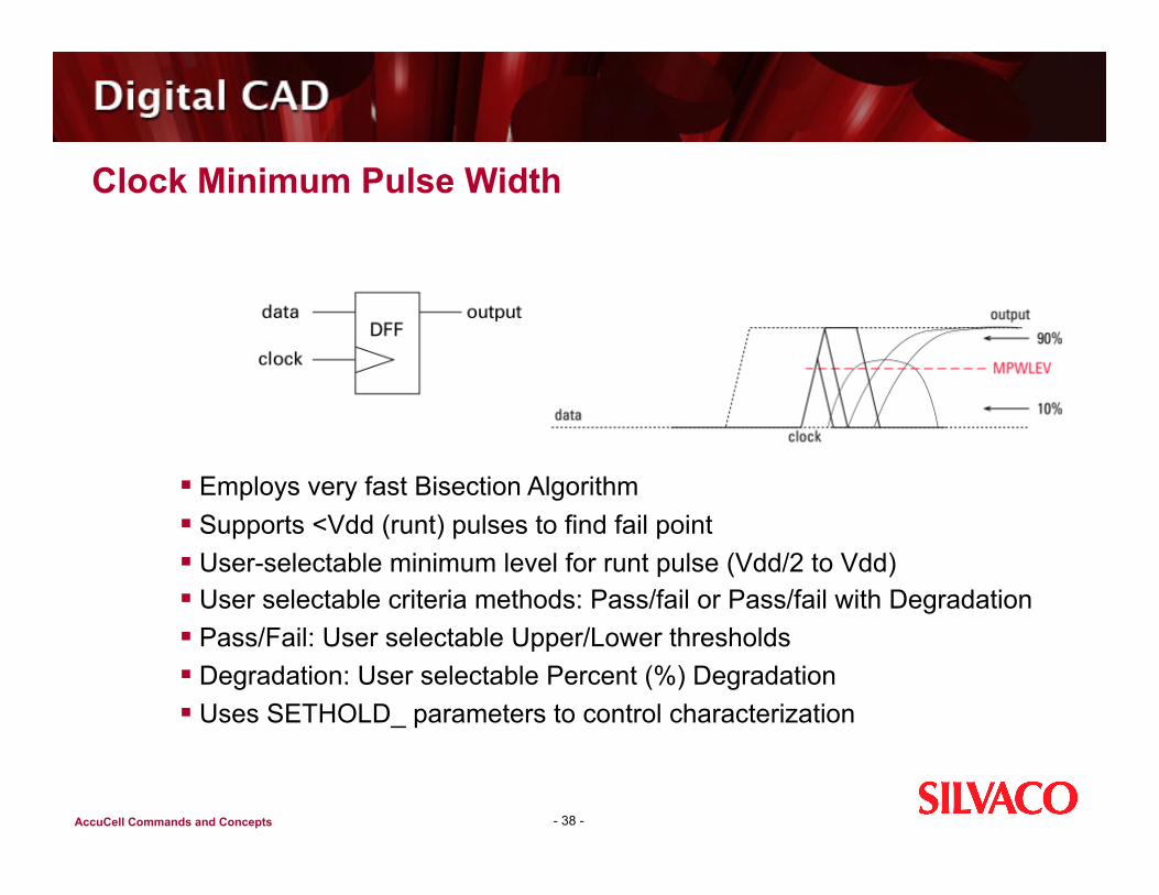
Clock Minimum Pulse Width
- 38 -
Employs very fast Bisection Algorithm Supports <Vdd (runt) pulses to find fail point User-selectable minimum level for runt pulse (Vdd/2 to Vdd) User selectable criteria methods: Pass/fail or Pass/fail with Degradation Pass/Fail: User selectable Upper/Lower thresholds Degradation: User selectable Percent (%) Degradation Uses SETHOLD_ parameters to control characterization
AccuCell Commands and Concepts
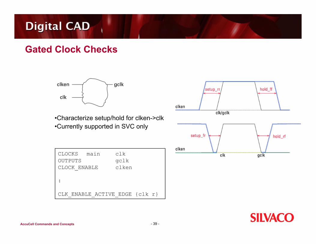
Gated Clock Checks
- 39 -
CLOCKS main clk OUTPUTS gclk CLOCK_ENABLE clken
:
CLK_ENABLE_ACTIVE_EDGE {clk r}
• Characterize setup/hold for clken->clk • Currently supported in SVC only

AccuCell Commands and Concepts
Load Dependency Between Output Pins
- 40 -
Within a Cell, the delay of a given buffered output of a cell is dependent upon its own loading as well as the loading on any combinationally connected un-buffered output.
For the example above, the CLK->Q delay is dependent on the load presented on NQ. In AccuCell, the user can specify that Characterization be done from CLK->NQ and then NQ->Q using the command
UNBUF_OUT_LIST
Excerpt from Synopsys.lib
pin (Q) { : timing { related_pin: NQ timing_sense: negative_unate : }
UNBUF_OUT_LIST {{NQ Q negative_unate} {…} {…} }
AccuCell Commands and Concepts
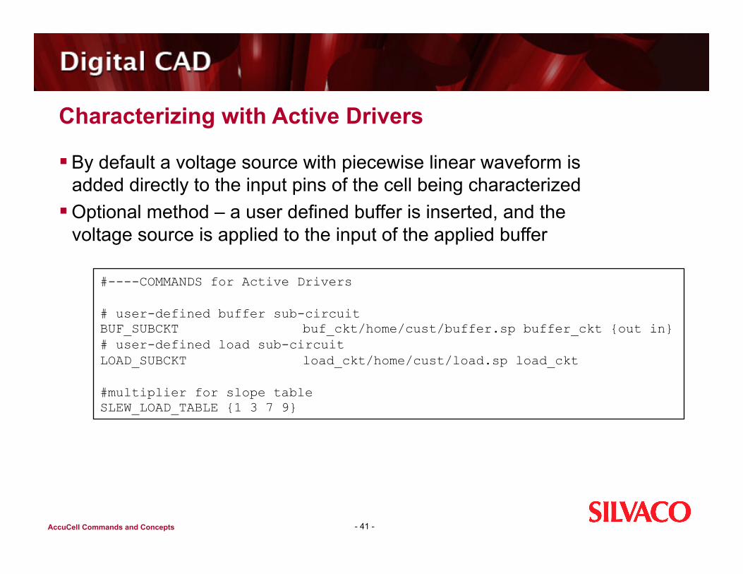
Characterizing with Active Drivers
By default a voltage source with piecewise linear waveform is added directly to the input pins of the cell being characterized
Optional method – a user defined buffer is inserted, and the voltage source is applied to the input of the applied buffer
- 41 -
#----COMMANDS for Active Drivers
# user-defined buffer sub-circuit BUF_SUBCKT buf_ckt/home/cust/buffer.sp buffer_ckt {out in} # user-defined load sub-circuit LOAD_SUBCKT load_ckt/home/cust/load.sp load_ckt
#multiplier for slope table SLEW_LOAD_TABLE {1 3 7 9}

AccuCell Commands and Concepts
Tri-states Characterization
Characterizes tri-state cells Function extracted automatically Measure
Input to Output arcs Enable to Output arcs
- 42 -
AccuCell Commands and Concepts
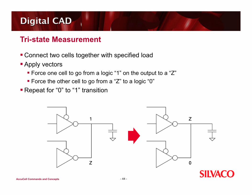
Tri-state Measurement
Cell is characterized as it is used in the design Driving another tri-state cell
Do not have to measure transistors being on or off No resistors needed for setup of the “Z state” initial condition
- 43 -
AccuCell Commands and Concepts
Tri-state Measurement
Connect two cells together with specified load Apply vectors
Force one cell to go from a logic “1” on the output to a “Z” Force the other cell to go from a “Z” to a logic “0”
Repeat for “0” to “1” transition
- 44 -
AccuCell Commands and Concepts
Agenda
Introduction to AccuCell and AccuCore Cell Characterization Introduction to AccuCell Getting Started with Accucell Methods of Characterization Sequential Cells Power Characterization
- 45 -
AccuCell Commands and Concepts
LAB 4 - Objectives
To become familiar with using AccuCell for Power Characterization
- 46 -
AccuCell Commands and Concepts
Need for Power Characterization
Low power applications Stand by time is critical for all battery powered devices
High Performance applications Higher operating frequencies Power bus sizing Cooling issues
- 47 -
AccuCell Commands and Concepts
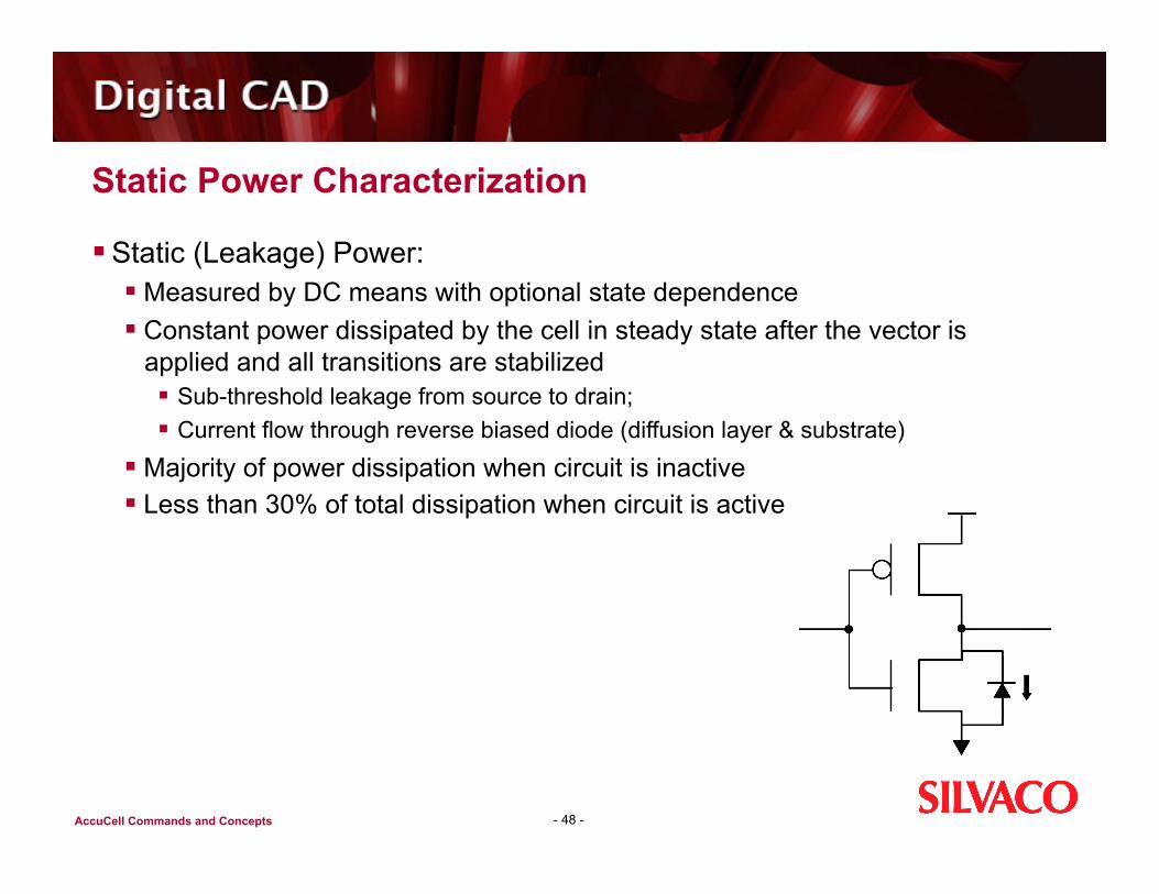
Static Power Characterization
Static (Leakage) Power: Measured by DC means with optional state dependence Constant power dissipated by the cell in steady state after the vector is
applied and all transitions are stabilized Sub-threshold leakage from source to drain; Current flow through reverse biased diode (diffusion layer & substrate)
Majority of power dissipation when circuit is inactive Less than 30% of total dissipation when circuit is active
- 48 -
AccuCell Commands and Concepts
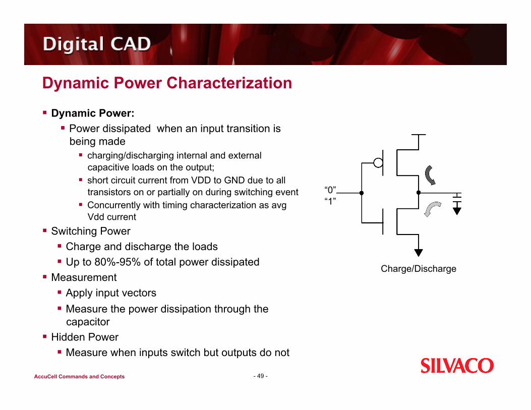
Dynamic Power Characterization
- 49 -
“0” “1”
Charge/Discharge
Dynamic Power: Power dissipated when an input transition is
being made charging/discharging internal and external
capacitive loads on the output; short circuit current from VDD to GND due to all
transistors on or partially on during switching event Concurrently with timing characterization as avg
Vdd current Switching Power
Charge and discharge the loads Up to 80%-95% of total power dissipated
Measurement Apply input vectors Measure the power dissipation through the
capacitor Hidden Power
Measure when inputs switch but outputs do not

AccuCell Commands and Concepts
Power Characterization Model
AccuCell uses the following circuit configuration for power characterization:
- 50 -
AccuCell Commands and Concepts
AccuCell Power Measurement Advantage
Current based! Curve’s nature: Peak, Monotonic, local MINs or MAXs, etc. Signal-processing-lie technique to filter unwanted numerical noises
- 51 -
AccuCell Commands and Concepts
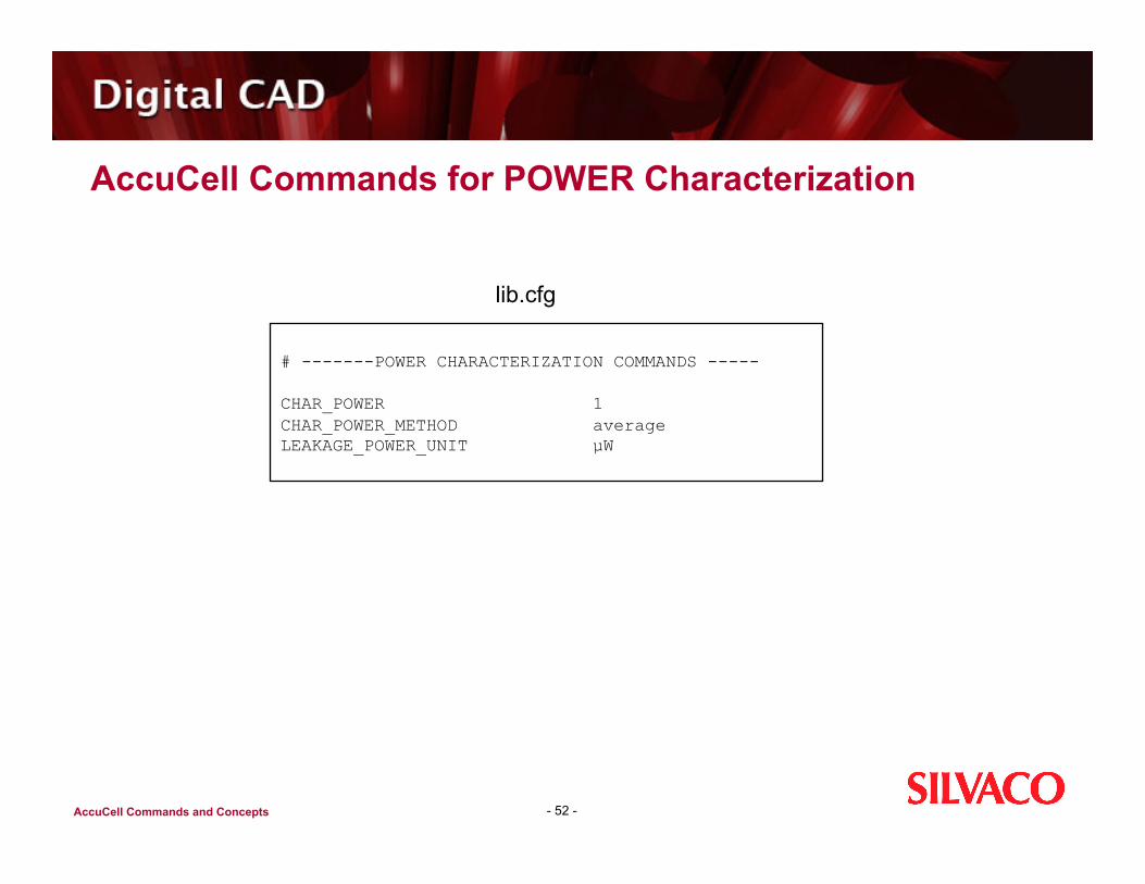
AccuCell Commands for POWER Characterization
- 52 -
# -------POWER CHARACTERIZATION COMMANDS -----
CHAR_POWER 1 CHAR_POWER_METHOD average LEAKAGE_POWER_UNIT µW
lib.cfg
AccuCell Commands and Concepts
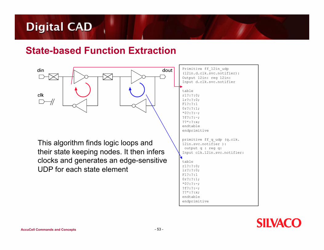
State-based Function Extraction
- 53 -
This algorithm finds logic loops and their state keeping nodes. It then infers clocks and generates an edge-sensitive UDP for each state element
Primitive ff_12in_udp (12in.d.clk.svc.notifier): Output 12in: reg 12in: Input d.clk.svc.notifier
table rl?:?:0; lr?:?:0; Fl?:?:1 0r?:?:1; *0?:?:-; ?f?:?:-; ??*:?:x; endtable endprimitive
primitive ff_q_udp (q.clk.12in.svc.notifier ): output q : reg q: Input clk.12in.svc.notifier:
table rl?:?:0; lr?:?:0; Fl?:?:1 0r?:?:1; *0?:?:-; ?f?:?:-; ??*:?:x; endtable endprimitive
AccuCell Commands and Concepts
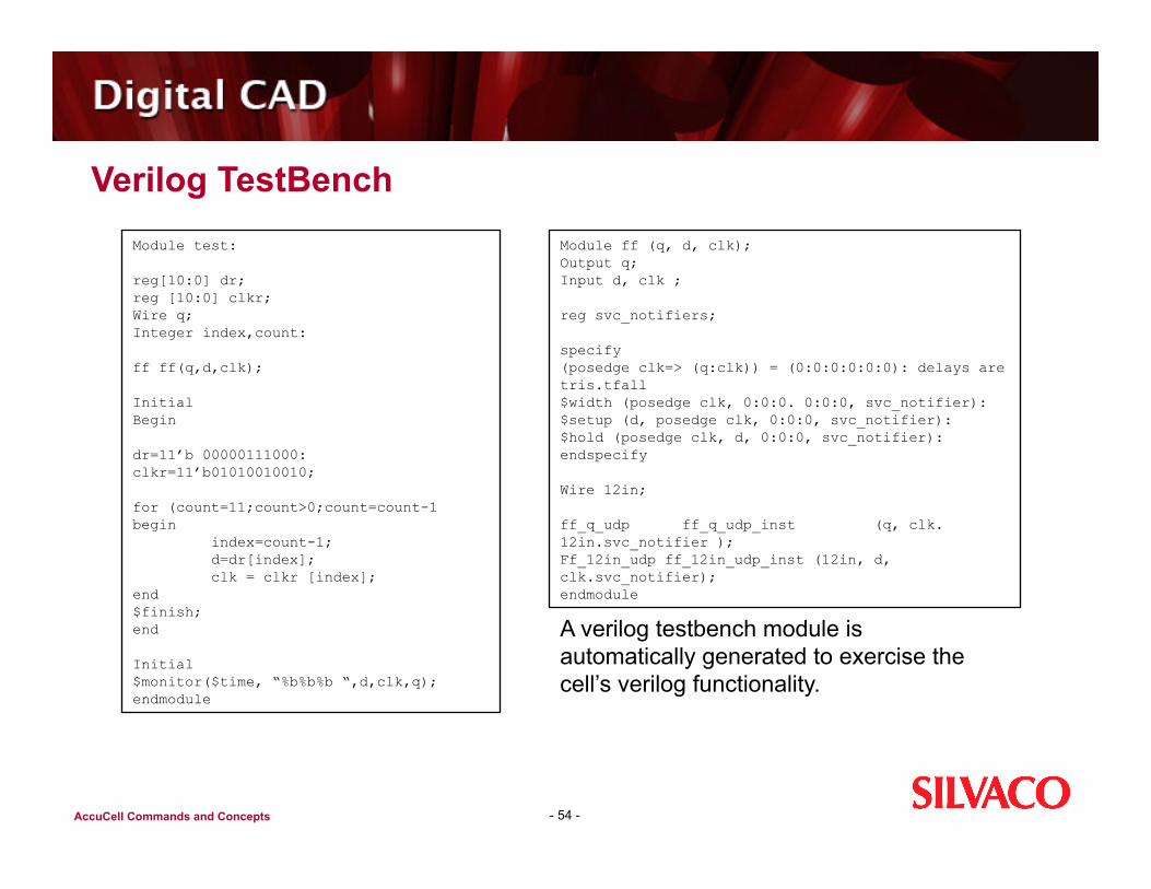
Verilog TestBench
- 54 -
Module test:
reg[10:0] dr; reg [10:0] clkr; Wire q; Integer index,count:
ff ff(q,d,clk);
Initial Begin
dr=11’b 00000111000: clkr=11’b01010010010;
for (count=11;count>0;count=count-1 begin index=count-1; d=dr[index]; clk = clkr [index]; end $finish; end
Initial $monitor($time, “%b%b%b “,d,clk,q); endmodule
Module ff (q, d, clk); Output q; Input d, clk ;
reg svc_notifiers;
specify (posedge clk=> (q:clk)) = (0:0:0:0:0:0): delays are tris.tfall $width (posedge clk, 0:0:0. 0:0:0, svc_notifier): $setup (d, posedge clk, 0:0:0, svc_notifier): $hold (posedge clk, d, 0:0:0, svc_notifier): endspecify
Wire 12in;
ff_q_udp ff_q_udp_inst (q, clk.12in.svc_notifier ); Ff_12in_udp ff_12in_udp_inst (12in, d, clk.svc_notifier); endmodule
A verilog testbench module is automatically generated to exercise the cell’s verilog functionality.

AccuCell Commands and Concepts
Verilog Timing
- 55 -
Timing metrics are represented in a specify block An SDF annotation flow is supported, so all values in the specify block
(min:ty:max) are set to zero. Unit delays for functional simulation are not instantiated
Timing Checks $setup $hold $width $recover $removal (not supported by all simulators)
VLOG_REMOVAL_TC_SUPPORTED controls suppression of this statement
State dependent paths, polarity, and tristate enables are supported

AccuCell Commands and Concepts
Sample Verilog
- 56 -
module nor (out, in1, in2); output out; input in1, in2;
reg svc_notifier; specify
if ((!in2)) (in1-=> out) = (0:0:0, 0:0:0); // delays are tris,tfall if none (in1-=>out) = (0:0::0, 0:0:0); // delays are tris,tfall if ((!in1)) (in2 -=> out) = (0:0:0, 0:0:0); // delays are tris,tfall ifnone (in2-=>out) = (0:0:0, 0:0:0); // delays are tris,tfall
endspecify wire net_out_1; not ( net_out_1 , in2 ) ; not ( out_sel_,in1 ) ; and ( out, net_out_1, out_sel_) ;
endmodule
module nand (out, in1, in2); output out; input in1, in2;
reg svc_notifier; specify
if ((in2)) (in1-=> out) = (0:0:0, 0:0:0); // delays are tris,tfall if none (in1-=>out) = (0:0::0, 0:0:0); // delays are tris,tfall if ((in1)) (in2 -=> out) = (0:0:0, 0:0:0); // delays are tris,tfall ifnone (in2-=>out) = (0:0:0, 0:0:0); // delays are tris,tfall
endspecify wire net_out_1; not ( net_out_1 , in2 ) ; not ( out_sel_,in1 ) ; or ( out, net_out_1, out_sel_) ;
endmodule
module or (out, in1, in2); output out; input in1, in2;
reg svc_notifier; specify
if ((!in2)) (in1+=> out) = (0:0:0, 0:0:0); // delays are tris,tfall if none (in1+=>out) = (0:0::0, 0:0:0); // delays are tris,tfall if ((!in1)) (in2 +=> out) = (0:0:0, 0:0:0); // delays are tris,tfall ifnone (in2+=>out) = (0:0:0, 0:0:0); // delays are tris,tfall
endspecify or ( out , 1n2, in1 );
endmodule
module and(out, in1, in2); output out; input in1, in2;
reg svc_notifier; specify
if ((in2)) (in1+=> out) = (0:0:0, 0:0:0); // delays are tris,tfall if none (in1+=>out) = (0:0::0, 0:0:0); // delays are tris,tfall if ((in1)) (in2+-=> out) = (0:0:0, 0:0:0); // delays are tris,tfall ifnone (in2+=>out) = (0:0:0, 0:0:0); // delays are tris,tfall
endspecify or ( out , 1n2, in1 );
endmodule

AccuCell Commands and Concepts
I/O Cell Characterization
Multi-Voltage I/O Cells Bi-Directional I/O Cells
Open drain, Pull-up keeper Schmitt trigger
Characterization: Delays/Slews Tri-state Measurements Capacitance Calculations
- 57 -
AccuCell Commands and Concepts
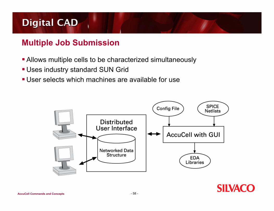
Multiple Job Submission
Allows multiple cells to be characterized simultaneously Uses industry standard SUN Grid User selects which machines are available for use
- 58 -

AccuCell Commands and Concepts
Summary
AccuCell for automated cell library characterization Automatic function extraction Automatic “smart” vector generation Automatic Table Selection (ATS) - accuracy
Supports complex cells Domino and dynamic logic Differential logic Cells with many inputs
Supports power characterization
- 59 -


