The Most Trusted Name In Measurement Electronic Preset Controller AccuLoad II TM - STD Operator Reference Issue/Rev. 1.0 (6/99) Bulletin MN06050L This manual applies to AccuLoad IIs operating with STD-02 and above firmware.
Transcript
The Most Trusted Name In Measurement
Electronic Preset Controller
AccuLoad IITM - STDOperator Reference
Issue/Rev. 1.0 (6/99) Bulletin MN06050L This manual applies to AccuLoad IIs operating with STD-02 and above firmware.
Warning
On initial power-up of a new unit or after installation of a new computer board, there are several alarms that will be triggered which cannot be cleared until the AccuLoad is programmed.
Warning
These Preset Devices must be used with fail-safe backup equipment to prevent accidental runaway delivery of product. Failure to provide fail-safe backup equipment could result in personal injury, property loss and equipment damage.
United States NIST Handbook 44 UR.3.5.1. and UR.3.5.2.
For compliance to United States NIST Handbook 44 UR.3.5.1. and UR.3.5.2. invoices printed using a mechanical numeric-only printer (e.g., Smith Load Printer) must contain in preprinted form, the following information:
a. Volume corrected to 60 degrees F b. API/C of E _____________________ c. Temperature ___________________ d. Gross Volume __________________ where the API/C of E, temperature, and gross volume may be hand-written on the ticket. Refer to Handbook 44, UR.3.5.1. and UR.3.5.2. for current requirements.
Table of Contents
iii
Section I - Introduction ............................................................................................................................................... 1
Product Description ................................................................................................................................................ 1 How to Use This Manual ........................................................................................................................................ 2
Section II - Program Mode ......................................................................................................................................... 3
Keypad Data Entry ................................................................................................................................................. 3 Entry to Program Mode ........................................................................................................................................... 4
Program Directory Selection ............................................................................................................................... 5 Specific Directory Selection ................................................................................................................................ 5 Sequential Directory Selection............................................................................................................................ 5 Exiting A Directory .............................................................................................................................................. 6 Program Code Selection..................................................................................................................................... 6 Second and Third Digit Selection........................................................................................................................ 6 Sequential Code Selection.................................................................................................................................. 7 Exiting Program Mode ........................................................................................................................................ 7
Exiting Program Mode ............................................................................................................................................ 7 Changing Program Code Parameters................................................................................................................. 8 Numeric Data ...................................................................................................................................................... 8 Options................................................................................................................................................................ 8 Alphanumeric Data ............................................................................................................................................. 8 Viewing the Help Messages.............................................................................................................................. 10
Section III - 100 - General Purpose Directory .......................................................................................................... 11
STD Display Customization Entry Table .............................................................................................................. 27 184 - Power-fail Alarm ...................................................................................................................................... 30 190 - Meter Position Disable............................................................................................................................. 30
Section IV - 200 - Flow Control Directory................................................................................................................. 31
Section VIII - 600 - Read Only Data Directory ......................................................................................................... 61
601 - Raw Non-resettable Totals ...................................................................................................................... 61 602 - Gross Non-resettable Totals.................................................................................................................... 61 603 - Gross @ Standard Temperature Non-resettable Totals.......................................................................... 61 604 - Net Non-resettable Totals........................................................................................................................ 61 605 - Mass Non-resettable Totals..................................................................................................................... 61 606 - Load Average Temperature..................................................................................................................... 61 607 - Load Average Pressure........................................................................................................................... 61 608 - Load Average Density ............................................................................................................................. 61 609 - Load Average Meter Factor ..................................................................................................................... 62 610 - Maximum and Used Local Storage Transactions.................................................................................... 62 611 - Injector 1 Non-resettable Totals............................................................................................................... 63 612 - Injector 2 Non-resettable Totals............................................................................................................... 63 613 - Injector 3 Non-resettable Totals............................................................................................................... 63 614 - Injector 4 Non-resettable Totals............................................................................................................... 63 640 - Protection of Program Codes 680-689 .................................................................................................... 63
Section IX -700 - Communications Directory ........................................................................................................... 64
701 - EIA-232 Communication Type................................................................................................................. 64 702 - EIA-232 Communication Control ............................................................................................................. 64 Notes................................................................................................................................................................. 67 703 - EIA-232 Baud Rate Select....................................................................................................................... 68 704 - EIA-232 Data Format............................................................................................................................... 68 705 - EIA-485 Communication Type................................................................................................................. 68 706 - EIA-485 Communication Control ............................................................................................................. 69
Section X - 800 - Inputs and Outputs Directory........................................................................................................ 90
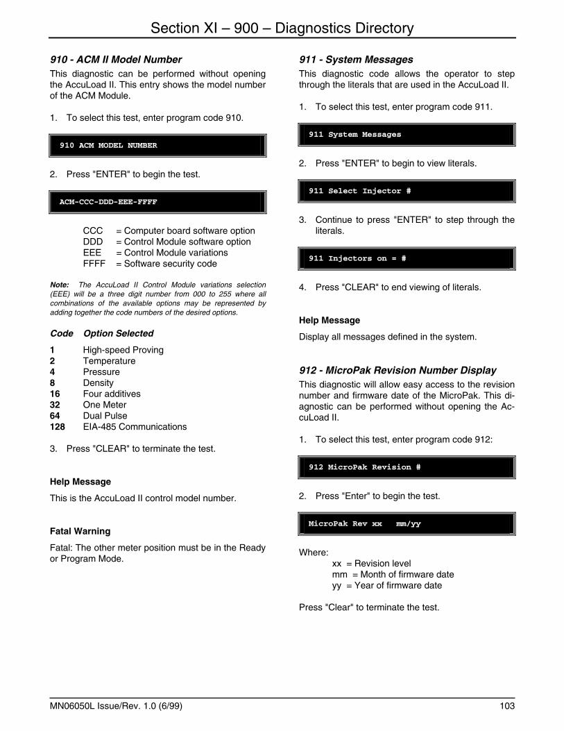
901 - Display Test ............................................................................................................................................. 99 902 - Keypad Test........................................................................................................................................... 100 903 - RTD Test ............................................................................................................................................... 100 904 - 4 - 20 mA Channel 1 Test...................................................................................................................... 100 905 - 4 - 20 mA Channel 2 Test...................................................................................................................... 101 906 - Internal Temperature Test ..................................................................................................................... 101 907 - Power Supply Test................................................................................................................................. 101 908 - CRC Display .......................................................................................................................................... 102 909 - AccuLoad II Model Number ................................................................................................................... 102 910 - ACM II Model Number ........................................................................................................................... 103 911 - System Messages ................................................................................................................................. 103 912 - MicroPak Revision Number Display ...................................................................................................... 103 913 - MicroPak Magnitude Display ................................................................................................................. 104 914 - MicroPak Drive Display.......................................................................................................................... 104 915 - MicroPak Tube Clock Period Display .................................................................................................... 104 916 - Calibration Event Counter...................................................................................................................... 105 917 - Configuration Event Counter ................................................................................................................. 105 940 - Protection of Program Codes 980-989 .................................................................................................. 105
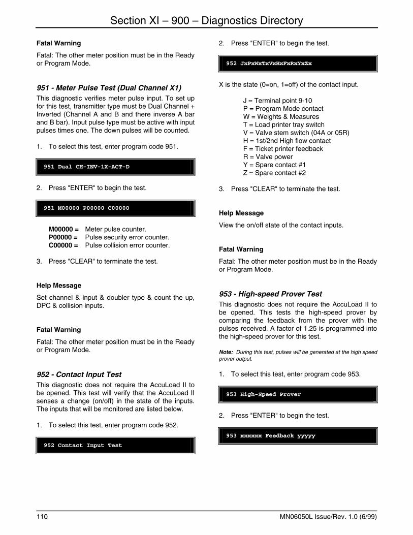
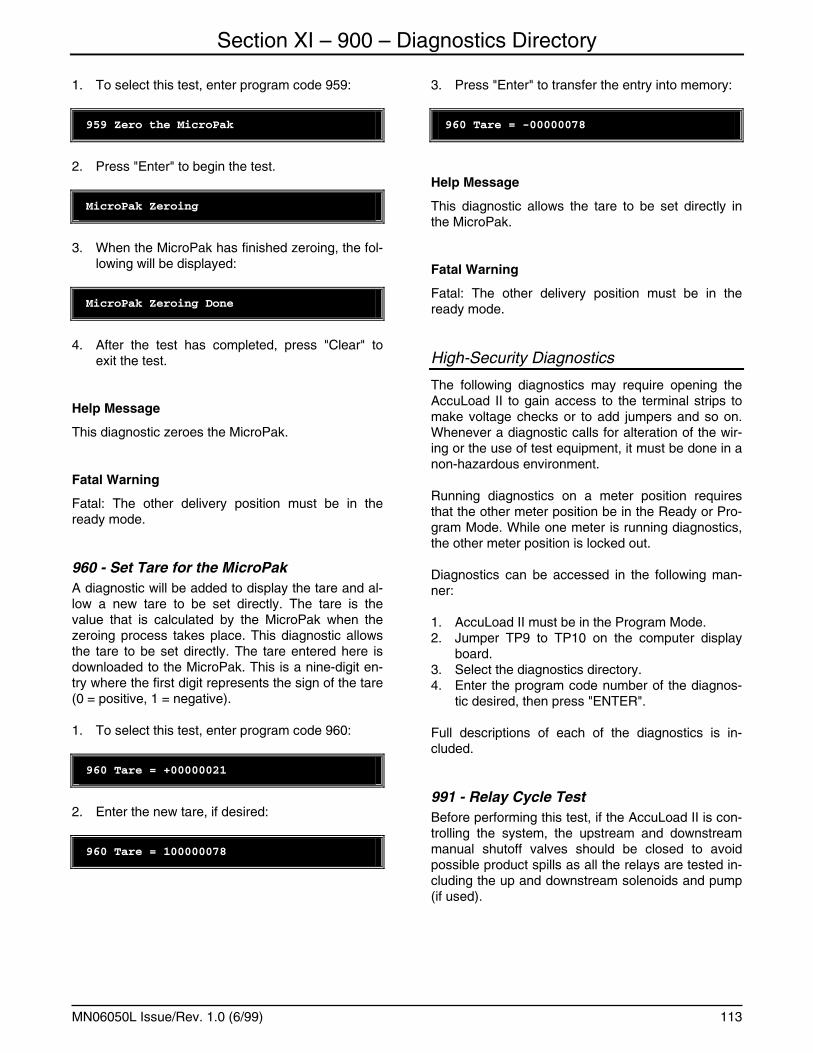
Keypad Selectable Diagnostics Using Test Equipment...................................................................................... 105 941 - Communication Test - EIA-232 - No Echo Back ................................................................................... 106 942 - Communication Test - EIA-232 - With Echo......................................................................................... 106 943 - Communication Test - EIA-485 - No Echo Back ................................................................................... 107 944 - Communication Test - EIA-485 - With Echo.......................................................................................... 107 945 - Meter Pulse Test (Single Channel X1) .................................................................................................. 108 946 - Meter Pulse Test (Single Channel X2) .................................................................................................. 108 947 - Meter Pulse Test - (Dual Channel X1)................................................................................................... 108 948 - Meter Pulse Test (Dual Channel X1) ..................................................................................................... 109 949 - Meter Pulse Test - (Dual Channel X2)................................................................................................... 109 950 - Meter Pulse Test (Dual Channel X1) ..................................................................................................... 109 951 - Meter Pulse Test (Dual Channel X1) ..................................................................................................... 110 952 - Contact Input Test ................................................................................................................................. 110 953 - High-speed Prover Test......................................................................................................................... 110 954 - Pulse #1 Output Test ............................................................................................................................. 111 955 - Pulse #2 Output Test ............................................................................................................................. 111 956 - Clear Local Storage ............................................................................................................................... 112 957 - Contact Output Test............................................................................................................................... 112 958 - Clear Configurable Report ..................................................................................................................... 112 959 - Zero the MicroPak ................................................................................................................................. 112 960 - Set Tare for the MicroPak...................................................................................................................... 113
Section XII - Appendix............................................................................................................................................ 118
Table of Contents
viii
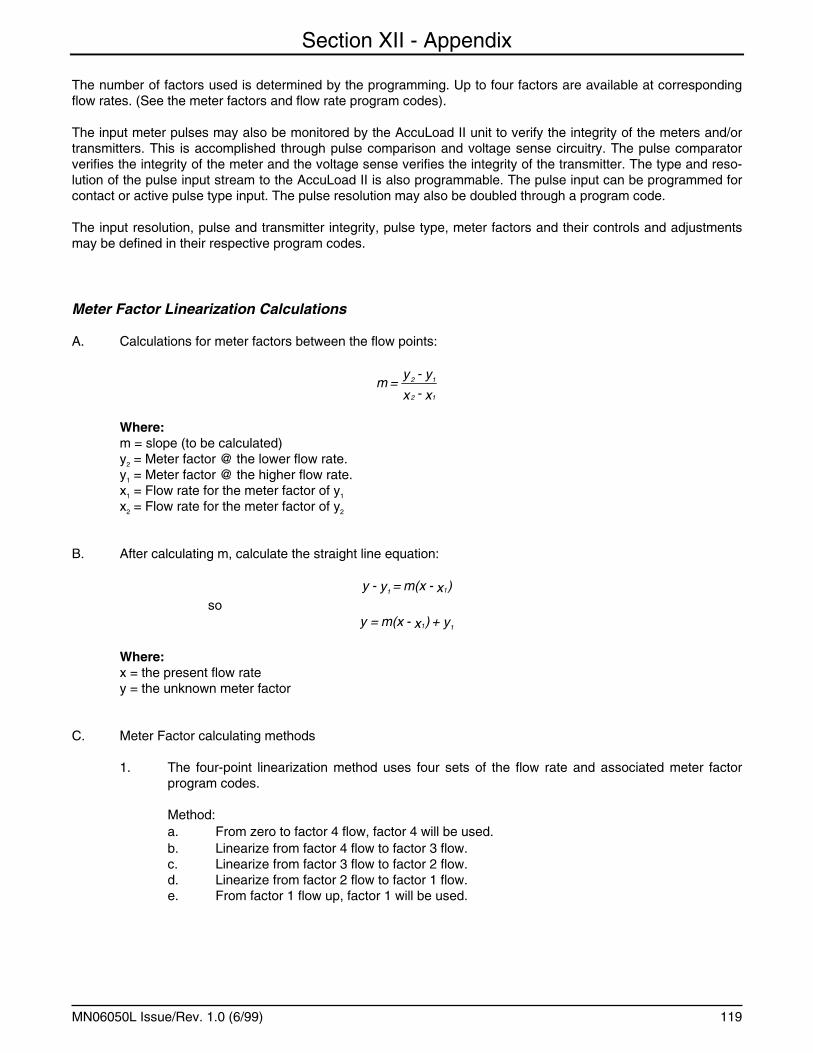
Appendix I - Meter Calibration ............................................................................................................................ 118 Meter Factor Linearization Calculations.......................................................................................................... 119 Meter Factor Adjustment Features ................................................................................................................. 120
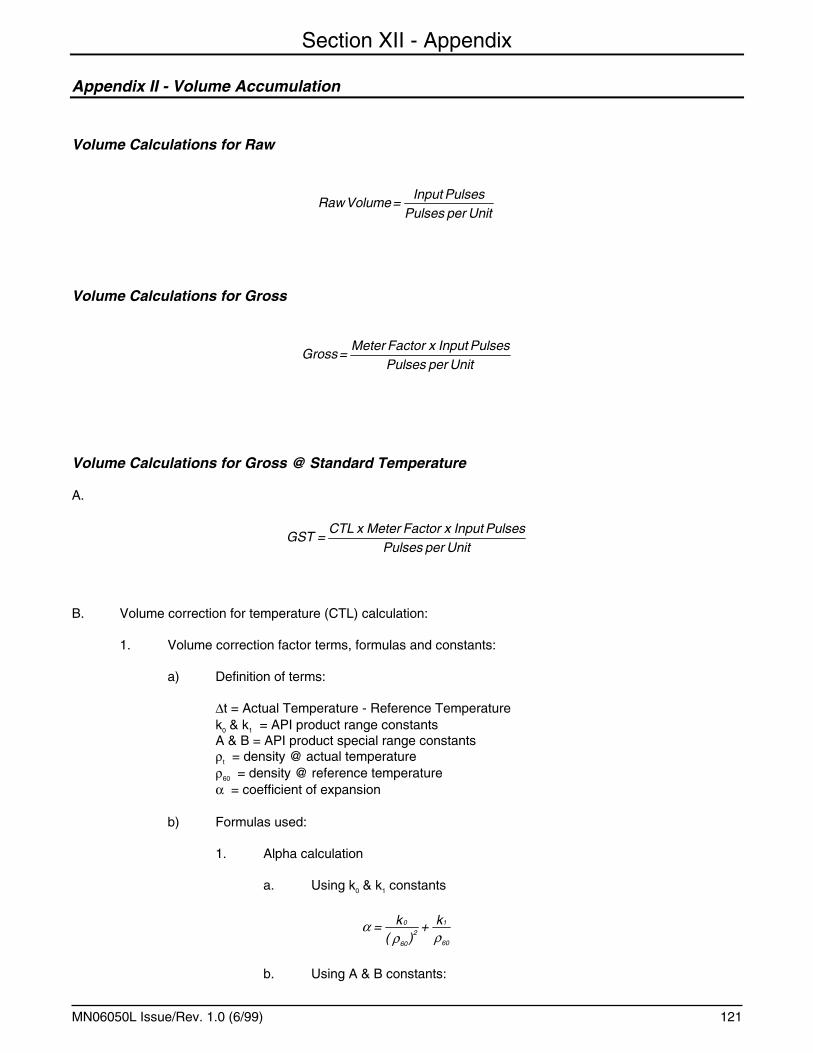
Appendix II - Volume Accumulation.................................................................................................................... 121 Volume Calculations for Raw.......................................................................................................................... 121 Volume Calculations for Gross ....................................................................................................................... 121 Volume Calculations for Gross @ Standard Temperature ............................................................................. 121
Appendix III - Volume Calculations for NET ....................................................................................................... 128 Appendix IV - Volume Calculations for Mass ..................................................................................................... 133 Appendix V - Pressure Control Operation and Options...................................................................................... 135 Appendix VI - Load Ticket .................................................................................................................................. 139
Section XIII - Index................................................................................................................................................. 140 Section XIV - Related Publications......................................................................................................................... 143
Section I – Introduction
MN06050L Issue/Rev. 1.0 (6/99) 1
This manual is to be used for AccuLoad II electronic preset delivery systems with STD-02 firmware and above. For units with STD-00 or STD-01 firmware, refer to manual MN06038.
Product Description
The Smith MeterTM AccuLoad II is a microprocessor-based electronic preset delivery system designed to simultaneously control the loading of petroleum or chemical products through two separate loading arms.
The AccuLoad II is designed to provide dependable service over a wide range of operating conditions. It is easy to operate and maintain, provides optimum measurement accuracy, display of current actual conditions, is easy to communicate with, and per-forms many loading system control functions.
Ease of operation and service permits rapid training of operators and service personnel. All entries into AccuLoad II are made quickly and easily through the rugged external keypad that is shared by both preset positions. Every keystroke is monitored and assis-tance is provided by auto prompting displays. Built-in "Help Messages" provide valuable information to aid in the programming of the instrument without resort-ing to a thick manual. Service is simplified with self-diagnostics that show parameters in need of adjust-ment or hardware that is malfunctioning.
Optimum measurement accuracy is attained through the continuous linearization of the meter factor with changes in flow rates. Volumetric correction is calcu-lated directly from published API equations providing precise volumetric measurement results. Precise automatic temperature, pressure compensation, and density correction are also available in the instru-ment.
The dynamic displays of the current actual operating conditions of the system provide the operator with valuable information while the system is operating. Some of the information that is available through the dynamic displays are the non-resettable totals along with the following:
• Current Time and Date • Current Flow Rate (units/min.) • Current Flow Rate (units/hour) • Current Temperature • Current API • Reference Density • Relative Density at Reference • Current Pressure and Vapor Pressure
• Current Meter Factor • Current CTL • Current CPL • Current Density • Current Raw Transaction Totals • Current Gross Transaction Totals • Current Gross at Standard Temperature Trans-
action Totals • Net Transaction Totals • Mass Transaction Totals • Injector Transaction Totals • Current Valve Status & Commanded Position • Load Average Temperature • Load Average Pressure • Load Average Density • Load Average Meter Factor • Raw Non-resettable Totals • Gross Non-resettable Totals • Gross at Standard Temperature Non-resettable
Totals • Net Non-resettable Totals • Mass Non-resettable Totals • Injector Non-resettable Totals • Input Module Status • Contact Output Status • Last Power Failure - Time and Date • Additive Injector Rates • Communications Diagnostics
Significant communication capability is available from the standard AccuLoad II. The instrument is pro-grammable for Polling, Polling and Authorization or complete Remote Control via communications. The EIA-232 communication port can be used to multi-drop up to 32 meter positions to an ASCII printer for printing load tickets or it can be used to network up to 32 meter positions to an automation system. Also available is an additional communication port that is EIA-485 interfacable. When used with a smart printer (one that will signal when it is out of paper, cover is open etc.), the AccuLoad II can alarm and display the reason for the printer not working. The "speak when spoken to" protocol of AccuLoad II is modeled after ISO Standard 1155. This allows quick access by an automation computer for operational and transaction information. The AccuLoad II also has a built-in communication analyzer to aid in the devel-opment and troubleshooting of communications. The AccuLoad II-STD Revision 16 and above firmware also has the capability of communicating directly with the new additive injector systems from Gate City (Blend Pak or Mini Pak) and Titan Industries (PAC-3). Using either the EIA-232 or the EIA-485 commu-nication ports the AccuLoad II will communicate with the Additive Injector System throughout the batch or the transaction, requesting the status of the injector and the volume of the additive that has been in-
Section I – Introduction
MN06050L Issue/Rev. 1.0 (6/99) 2
jected. Also developed with the additive communica-tions is a pass through mode of communications that will allow the supervisory computer to talk directly to the additive system through the AccuLoad. For addi-tional information on the AccuLoad II communica-tions, see the Communications Manual (Bulletin MN06040).
Several loading system control functions are pro-vided by AccuLoad II: Additive Injection, Pump Con-trol, Alarm Control, Valve Control, Back Pressure Control, and Automatic Adjustment of Final Trip Point.
• Up to four different additive injectors can be si-multaneously paced or controlled through com-munications per preset position.
• The AccuLoad II will monitor and totalize the vol-ume of additive injected by the four additive in-jectors if the additive monitoring option is pur-chased.
• A contact is available to start and stop a pump or other electrically operated equipment as well as program codes that will set the time delay of that start or stop.
• A programmable alarm contact is available. It can be closed on a valve fault, on any alarm or not at all depending on how it is programmed. A second alarm output is also available. It can be configured to be activated on any or all alarms.
• The AccuLoad II contains the intelligence to con-trol a Smith Model 210 or 215 Digital Control Valve which will provide low flow start and multi-stage shut-down.
• Contains the intelligence to automatically reduce the flow of product and ensure the flow is within the pumping capabilities of the system.
• AccuLoad II, if so programmed, will automat-ically adjust the final trip point of the batch (Pre-set).
Critical functions such as minimum flow rate, excess flow rate, temperature detection, preset volume over-run and memory retention, are monitored by internal circuits. Any failure will signal closure of the valve. Should the valve fail to close within 10 seconds after having been signaled, a contact is closed. This can be wired through external relays to shut off the pump and/or kill power circuits.
Environmental fluctuations within specified limits have virtually no effect on the operation of this con-trol system. AccuLoad II is available in an explosion-proof housing for hazardous locations. (See Bulletin SS06012 for specifications.)
How to Use This Manual
This manual is divided into 14 sections: Introduction, Program Mode, sections for each of the 9 directories of the AccuLoad II, an Appendix, the Index, and Re-lated Publications.
"Program Mode" describes how to get into the Pro-gram Mode, Program Directory Selection, Program Code Selection, how to change a program parameter and how to view the Help Messages.
"The Directories" give a description of each program code in the directory, the type of entry required for each code, the Help Message and Critical and Fatal Warnings if they apply to the individual code.
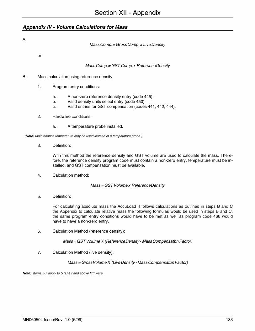
The "Appendix" is divided into six parts and is pro-vided as a reference for meter calibration, volume correction factor, volume calculations for pressure, volume calculations for mass, pressure control op-eration and the product receipt ticket. The appendix goes into detail on how these subjects are handled in the AccuLoad II.
The "Index" is provided to aid the user to easily lo-cate the topic or program code that he is looking for.
The examples presented in this manual are for clarity and your convenience. The values might vary for your particular installation and/or operation.
Section II – Program Mode
MN06050L Issue/Rev. 1.0 (6/99) 3
Keypad Data Entry
All programming information is entered via the key-pad. The program codes for AccuLoad II are divided into nine directories as follows:
Code Description
100 General Purpose Directory 200 Flow Control Directory 300 Volume Accuracy Directory 400 Temperature & Density Directory 500 Pressure Directory 600 Read Only Data Directory 700 Communications Directory 800 Inputs & Outputs Directory 900 Diagnostics Directory These directories are then subdivided into three sec-tions. Under program protection are the codes that are low security items or those that do not affect vol-ume accuracy. Such are the status of the various alarms, accumulative totalizers, date and time and various other read only codes. The second digit of these codes will always be zero through three. The criteria for entering the Program Mode in preset posi-tion one or two and changing a parameter under this protection will consist of the following:
1. The program contact is closed.
2. The access code for the respective preset posi-tion has been correctly entered.
The Weights and Measures codes are high-security items or those that involved in volume accuracy. The second digit of these codes will always be four through seven. The criteria for entering the Program Mode and changing these codes in preset position one or two will consist of the following:
1. The program contact is closed.
2. The Weights and Measures contact is closed.
3. The access code for the respective preset posi-tion has been correctly entered.
Note: These codes can be viewed without the Weights and Measures contact in, but cannot be changed.
Program codes that have a second digit of eight can be protected by either the program contact or by both the program contact and the Weights and Measures contact. The security requirements of these codes may vary under various Weights and Measures agencies' guidelines. The criteria for en-tering the Program Mode and changing these codes
in preset position one or two will vary depending on how code X40 is programmed, where X equals the directory number of the codes.
Under the Special High-Security Mode of protection are codes whose use may be sensitive under vari-ous Weights and Measures agencies' guidelines or affect volume accuracy. The second digit of these codes will always be a nine. The criteria for entering the Special High-Security Mode and programming the codes in preset position one or two will consist of the following:
1. The program contact is closed.
2. The Weights and Measures contact is closed.
3. The access code for the respective meter posi-tion has been correctly entered.
4. A board level hardware jumper is installed be-tween TP9 and TP10 on the computer board. These points are located on the lower left half of the board.
Note: The program contact and the Weights and Measures con-tact are shared by both preset positions.
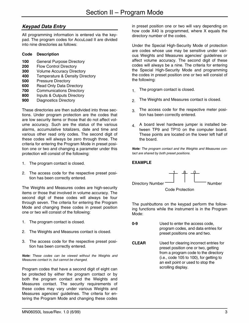
EXAMPLE
1 8 0
Directory Number Number
Code Protection
The pushbuttons on the keypad perform the follow-ing functions while the instrument is in the Program Mode:
0-9 Used to enter the access code, program codes, and data entries for preset positions one and two.
CLEAR Used for clearing incorrect entries for preset position one or two, getting from a program code to the directory (i.e., code 105 to 100), for getting to an exit point or used to stop the scrolling display.
Section II – Program Mode
MN06050L Issue/Rev. 1.0 (6/99) 4
ENTER Used to enter the Program Mode security access code, to enter program data for preset position one or two, and for exiting the Program Mode.
START Not used in Program Mode.
SET Used for stepping through the program codes in sequence for preset position one or two.
PRINT Used for Help Messages for preset position one or two.
STOP Not used in Program Mode.
AccuLoad II
PRINT SET START CLEAR ENTER PRINT SET START CLEAR ENTER
STOP
STOP
1 2 3 4 5
6 7 8 9 0
Entry to Program Mode
1. Close the Program Mode contact (unless already permanently wired closed). This will provide the first step for access to program codes with a second digit of zero through three.
Note: Weights & Measures codes can be viewed but not changed unless the Weights and Measures contact is also closed either before entry into Program Mode or while in the Program Mode.
Ready 1:10:31
2. Press "ENTER","ENTER". This clears the dis-play.
3. Enter the four-digit access code ("0000" preset at factory). For security, any digit entered will be displayed as an "X".
XXXX
4. Press "ENTER". This checks for the proper ac-
cess code. If it is correct, the following will be displayed:
Enter Dir or Program #
Note: If an incorrect access code was entered, the following prompt will appear:
** Error Press Clear **
Section II – Program Mode
MN06050L Issue/Rev. 1.0 (6/99) 5
Press "CLEAR". The display will return to "READY".
Unleaded Ready 1:10:31
Repeat Steps 2, 3 and 4 to re-enter the Program Mode.
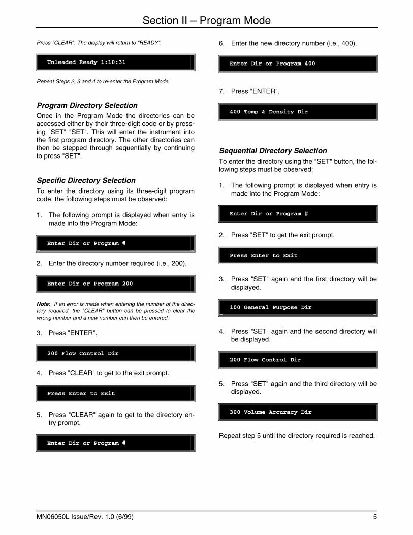
Program Directory Selection Once in the Program Mode the directories can be accessed either by their three-digit code or by press-ing "SET" "SET". This will enter the instrument into the first program directory. The other directories can then be stepped through sequentially by continuing to press "SET".
Specific Directory Selection To enter the directory using its three-digit program code, the following steps must be observed:
1. The following prompt is displayed when entry is made into the Program Mode:
Enter Dir or Program #
2. Enter the directory number required (i.e., 200).
Enter Dir or Program 200
Note: If an error is made when entering the number of the direc-tory required, the "CLEAR" button can be pressed to clear the wrong number and a new number can then be entered.
3. Press "ENTER".
200 Flow Control Dir
4. Press "CLEAR" to get to the exit prompt.
Press Enter to Exit
5. Press "CLEAR" again to get to the directory en-
try prompt.
Enter Dir or Program #
6. Enter the new directory number (i.e., 400).
Enter Dir or Program 400
7. Press "ENTER".
400 Temp & Density Dir
Sequential Directory Selection To enter the directory using the "SET" button, the fol-lowing steps must be observed:
1. The following prompt is displayed when entry is made into the Program Mode:
Enter Dir or Program #
2. Press "SET" to get the exit prompt.
Press Enter to Exit
3. Press "SET" again and the first directory will be displayed.
100 General Purpose Dir
4. Press "SET" again and the second directory will be displayed.
200 Flow Control Dir
5. Press "SET" again and the third directory will be displayed.
300 Volume Accuracy Dir
Repeat step 5 until the directory required is reached.
Section II – Program Mode
MN06050L Issue/Rev. 1.0 (6/99) 6
Exiting A Directory To exit a directory and to enter the next directory, fol-low these steps:
1. From the last program code in the directory.
190 0 Meter Enabled
2. Press "SET".
Press Enter to Exit Dir
3. Press "ENTER".
200 Flow Control Dir
Program Code Selection Once in the Program Mode, the codes can be ac-cessed either by their three digit number, going to the directories and then into the code using the sec-ond and third digits, or sequentially once in the pro-gram codes.
Note: Weights & Measures codes can be viewed but not changed unless the Weights and Measures contact was closed before entry into Program Mode.
1. From the entry to the Program Mode.
Enter Dir or Program #
2. Enter the desired program code using the key-pad (i.e., 106).
Enter Dir or Program 106
3. Press "ENTER".
106 00 Dynamic Time-out
4. If another code is required, press "CLEAR". The following display will appear:
100 General Purpose Dir
5. Press "CLEAR" again.
Press Enter to Exit
6. Press "CLEAR" again.
Enter Dir or Program #
7. Enter the new code (i.e., 210).
Enter Dir or Program 210
8. Press "ENTER".
210 0000 1st Trip Point
Note: If a code that is currently unassigned (e.g., "135") is en-tered, the following prompt will appear:
135 Invalid Program Code
Second and Third Digit Selection If it is desired to review or change a code that is in the same directory that has been accessed, the fol-lowing steps should be followed:
1. From the directory.
200 Flow Control Dir
2. Press "ENTER".
Enter Program #
Section II – Program Mode
MN06050L Issue/Rev. 1.0 (6/99) 7
3. Enter the second and third digit of the code re-quired (i.e., 10).
Enter Program 10
4. Press "ENTER".
210 0000 1st Trip Point
5. To access another code in the same directory, press "CLEAR" to get back to the directory.
200 Flow Control Dir
6. Press "ENTER".
200 Enter Program #
7. Enter the second and third digit of the code re-quired (i.e., 41).
200 Enter Program 41
8. Press "ENTER".
241 0 No Valve Security
Repeat steps 5 through 8 for each code that is re-quired to be accessed.
Sequential Code Selection If it is desired to review the codes in numerical se-quence, press "SET" to advance by one code rather than entering the program code.
1. From the entry into the Program Mode:
101 No Alarms Present
2. Press "SET"...
102 No Alarms Present
3. Press "SET" ...
103 No Alarms Present
4. Press "SET" again ...
104 17:24 Mil Time
5. Press "SET" again ...
105 02-23-89 Date
Etc. ...
Note: When using this method of stepping through the program codes, the instrument will skip invalid codes and only display the valid codes.
EXAMPLE:
107 0 Flash No Totals
Press "SET".
140 0 Weights & Measures
Note: If "SET" is pressed and held, AccuLoad II will scroll through the program codes.
Exiting Program Mode To return to the Run Mode either open the Program Mode contact and press "SET" or follow the steps listed below.
1. From the program code or directory.
200 Flow Control Dir
2. Press "CLEAR".
Press Enter to Exit
Section II – Program Mode
MN06050L Issue/Rev. 1.0 (6/99) 8
3. Press "ENTER".
Unleaded Ready 17:33:33
Changing Program Code Parameters The program codes represent parameters that can be changed to either enhance the performance of AccuLoad II or can be changed because of applica-tion changes. There are three types of parameters in AccuLoad II: the codes that require numerical data, the codes where choices have to be made on option 1, 2, 3 etc., and the codes where alphanumeric data is entered. Once a code has been selected, its pro-grammed contents can be changed by entering a new value through the keypad.
Numeric Data The numeric data is entered into the program codes via the keypad just as numbers are entered into a calculator. The number of digits for each entry is listed in the Programming Workbook (AB06029) and in the description of each code in this manual.
EXAMPLE: To change the parameters for the high flow rate:
1. View the contents of Code 207 via one of the methods previously described.
207 0600 High Flow Rate
2. To specify a new first high flow rate enter the rate required (i.e., 450).
207 0600 High Flow R 450
3. Press "ENTER" to store the new value. The dis-play will read as follows while data is being stored:
207 ** STORING DATA **
4. After the data is stored the display will then read:
207 0450 High Flow Rate
Note: If an incorrect value is entered on the screen and has not been stored, the value can be cleared by pressing "CLEAR" twice and a new value can then be entered.
Options The codes that have several options (i.e., 1, 2, 3, etc.,) are changed by entering the number that corre-lates to the option that is required for the application.
EXAMPLE: To change the parameters for the transaction control:
1. View the contents of code 301 via one of the methods previously described.
301 0 Local Tray Switch
2. To specify a different option, enter the new one digit number of the option desired (i.e., 1).
301 0 Local Tray Switch1
3. Press "ENTER" to store the new option, the dis-play will read ** STORING DATA ** while the new option is being stored.
301 ** STORING DATA **
4. After the data is stored the display will then read:
301 1 Print Key
Note: An entry other than "0" through "2" will result in an error message being scrolled across the display "Fatal: Entry is out of specified range". Press "CLEAR" to stop the scrolling message and to return to the original display. Press "CLEAR" again to clear the number that was in error and then retry.
Alphanumeric Data The codes that require alphanumeric data entered in them are the codes that will display product mes-sages, prompt messages or permissive sense mes-sages on the displays of AccuLoad II or will provide information to be printed out on the Bill of Lading Emulation. When adding or changing information in these alphanumeric program codes, the keys listed below perform the following functions:
Key Description
Section II – Program Mode
MN06050L Issue/Rev. 1.0 (6/99) 9
"ENTER" Enters the data into the instrument's memory.
"1" Positions the cursor so that it is pointing at the character to be changed or added.
"2" Increments the character one position.
"3" Decrements the character one position.
"4" Increments the character from one block of characters to another. For example, changing from upper case letters to lower case letters. The blocks of charac-ters that are available in AccuLoad II are as follows:
• A B C D E F G H I J K L M N O P Q R S T U V W X Y Z
• a b c d e f g h i j k l m n o p q r s t u v w x y z • 0 1 2 3 4 5 6 7 8 9 • + ! " # $ % & ` ( ) , - . / : ; < = > @ [ \ ^ _ ' {l} ° ? *
space
1. View the contents of code 181 via one of the methods previously described.
181 = Prod Msg
2. To change/add information press "1", this will position the cursor so that it is pointing to the po-sition to be changed.
181 < = Prod Msg
3. To add the description "Unleaded" as the prod-uct message, press "4". This will advance the blocks of characters to "A".
181 A< = Prod Msg
4. Press "4" to advance the blocks of characters to "a".
181 a< = Prod Msg
5. Press "3" to decrement the character.
181 Z< = Prod Msg
6. Repeat step 5 until the desired letter is displayed "U".
181 U< = Prod Msg
7. Press "1" to move the cursor to the next position.
181 U < = Prod Msg
8. Press "4" until the group of characters that is de-sired is displayed (i.e., 0).
181 U0< = Prod Msg
9. Press "3" to decrement the character.
181 Uz< = Prod Msg
10. Repeat step 9 until the desired letter is displayed "n".
181 Un< = Prod Msg
11. Press "1" to move the cursor to the next position.
181 Un < = Prod Msg
12. Press "4" until the group of characters that is re-quired is displayed (i.e., a).
181 Una< = Prod Msg
13. Press "2" to increment the character.
181 Unb< = Prod Msg
Section II – Program Mode
MN06050L Issue/Rev. 1.0 (6/99) 10
14. Repeat step 13 until the desired letter is dis-played "l".
181 Unl< = Prod Msg
15. Continue advancing and changing/adding char-acters until the desired message is displayed.
181 Unleaded = Prod Msg
16. Advance the arrow (Press "1") until only the message is displayed. The arrow will wrap if "1" is continuously pressed.
181 U<leaded = Prod Msg
17. Press "ENTER" to store the message. The dis-play will read as follows while the data is being stored:
181 ** STORING DATA **
18. After the data is stored the display will then read:
181 Unleaded = Prod Msg
Note: If "ENTER" is not pressed, the data will not be stored in memory and will revert to the previous display.
Viewing the Help Messages The AccuLoad II features unique Help Messages that allow the operator to review what is required or what the options are for an individual program code by simply pressing the "PRINT" key while in the Pro-gram Mode. The Help Messages will scroll across the display when the "PRINT" key is pressed. The message will continue to scroll across the display un-til the "CLEAR" key is pressed.
EXAMPLE: To view the help message for program code 301 (Transaction Control):
1. View the contents of code 301 via one of the methods previously described.
301 0 Local Tray Switch
2. To view the Help Message press the "PRINT" key. This message will scroll across the display:
Select method of Transac
Tion Control: Remote, Lo
cal, Print.
3. To return to the program code, press the "CLEAR" key.
301 0 Local Tray Switch
Section III – 100 – General Purpose Directory
MN06050L Issue/Rev. 1.0 (6/99) 11
101 - Alarm Check and Reset This program code is used to check the alarm(s) that have been triggered and to clear the alarm (after the fault has been corrected) to allow continued opera-tion.
The following faults will cause the AccuLoad II to alarm and signal the valve(s) to close. Depending on how program code 143 is programmed, the faults may energize the alarm relay.
Code : Fault
AC: Additive Communications - Indicates a failure on the master/slave communications line between the AccuLoad II and the Additive Injector Subsystem.
AC: Add Com Alarm
Note: Alarm applies to STD-16 and above firmware.
A2: Indicates that the printer cover is open on the printer that is wired to the EIA-232 port.
101 A2: Print Cover Open
A4: Indicates that the printer cover is open on the printer that is wired to the EIA-485 port.
101 A4: Print Cover Open
BP: Indicates that the back pressure cannot be maintained for the minimum back pressure flow rate entry set.
101 BP: Back Pressure
B2: Indicates that the buffer is full on the printer that is wired to the EIA-232 port.
101 B2: Buffer Overflow
B4: Indicates that the buffer is full on the printer that is wired to the EIA-485 port.
101 B4: Buffer Overflow
CM: Communications - Indicates a failure on one of the communication channels.
101 CM: Communications
DA: Diagnostic - The AccuLoad II contains 12 types of diagnostic alarms. These alarms are as fol-lows:
ROM Error - When displayed, this indicates a ROM error.
101 DA: ROM UXX Bad
XX = Identifier of ROM that failed.
RAM Error - When displayed, this indicates a RAM failure.
101 DA: RAM XXXX Bad
XXXX = The address of the first failed location
Programming Error - Will alarm when an invalid en-try is made in the Programming Mode.
101 DA: Program Error XXX
XXX = program code with incorrect entry
Data Retention Error - When displayed, this indi-cates that RAM data retention may be faulty. This test is performed only on power-up.
101 DA: Data Retention
Section III – 100 – General Purpose Directory
MN06050L Issue/Rev. 1.0 (6/99) 12
EEPROM Error - When displayed, this indicates that the EEPROM failed.
101 DA: EEPROM XXXX Bad
XXXX = The address of the failed location
Watchdog Alarm - Indicates an internal check fea-ture has detected a possible operational problem in the microprocessor that may have affected informa-tion stored in memory. A complete review of all pro-gram codes stored in memory must be made to con-firm their correctness.
101 DA: Watchdog Alarm
Display Error - Indicates an error in data transmis-sion to the display.
101 DA: Display Error
Display Download Required - Indicates a failure in downloading the display firmware.
101 DA: Display Boot Req
Control Module - Indicates a communication failure with the AccuLoad II control module (ACM).
101 DA: Control Module
Security Code Violation - Indicates the software security code does not match the ACM security code.
101 DA: Security Code
Software Version Mismatch - Indicates that the AccuLoad II firmware version does not match the ACM Version.
101 DA: Software Version
Internal Temperature Alarm - Indicates that the temperature inside the AccuLoad II housing has ex-ceeded the limit for reliable operation.
101 DA: Internal Temp
DP: Down Pulse Error - Indicates consecutive down pulses greater than or equal to the dual pulse comparator error count.
101 DP: Down Pulse Error
DR: Density Transducer - Indicates a failure or an out-of-range condition.
101 DR: Density Trans
D2: Indicates that the printer is not selected for the EIA-232 port.
101 D2: Print Deselected
D4: Indicates that the printer is not selected for the EIA-485 port.
101 D2: Print Deselected
E2: Indicates there is a printer error on the printer that is wired to the EIA-232 port.
101 E2: Printer Error
E4: Indicates there is a printer error on the printer that is wired to the EIA-485 port.
101 E2: Printer Error
Section III – 100 – General Purpose Directory
MN06050L Issue/Rev. 1.0 (6/99) 13
F1: Injector 1 - Indicates that the additive #1 feed-back has exceeded the programmed number of er-rors.
101 F1: Add 1 Feedback
F2: Injector 2 - Indicates that the additive #2 feed-back has exceeded the programmed number of er-rors.
101 F2: Add 1 Feedback
F3: Injector 3 - Indicates that the additive #3 feed-back has exceeded the programmed number of er-rors.
101 F2: Add 1 Feedback
F4: Injector 4 - Indicates that the additive #4 feed-back has exceeded the programmed number of er-rors.
101 F4: Add 1 Feedback
HD: High Density - Indicates the density transducer is out of range of the high alarm setting.
101 CM: Communications
HF: Excess High Flow - Indicates that the flow rate has exceeded the flow limit set in the excess high flow program code for more than 4 seconds.
101 HF: Excess High Flow
HP: High Pressure - Indicates that the pressure transducer is out of range of the high pressure set-ting.
101 HP: High Pressure
HT: High Temperature - Indicates that the tem-perature probe or transducer is out of range of the high temperature setting.
101 HT: High Temperature
H2: Indicates that there is a printer hardware failure on the printer that is wired to the EIA-232 port.
101 H2: Printer Hardware
H4: Indicates that there is a printer hardware failure on the printer that is wired to the EIA-485 port.
101 H4: Printer Hardware
IA: Injector Alarm Pending - Indicates that there is an Additive Injector Subsystem Alarm.
101 IA: Inj Alrm Pending
Note: Alarm applies to STD-16 and above firmware.
I2: Indicates that the printer wired to the EIA-232 port is not responding.
101 I2: Print Not Respon
I4: Indicates that the printer wired to the EIA-485 port is not responding.
101 I4: Print Not Respon
K1: Low Additive 1 - Indicates that not enough ad-ditive was injected during one cycle or an average of several cycles for additive 1.
101 K1: Low Additive 1
Note: Alarm applies to STD-16 and above firmware.
Section III – 100 – General Purpose Directory
MN06050L Issue/Rev. 1.0 (6/99) 14
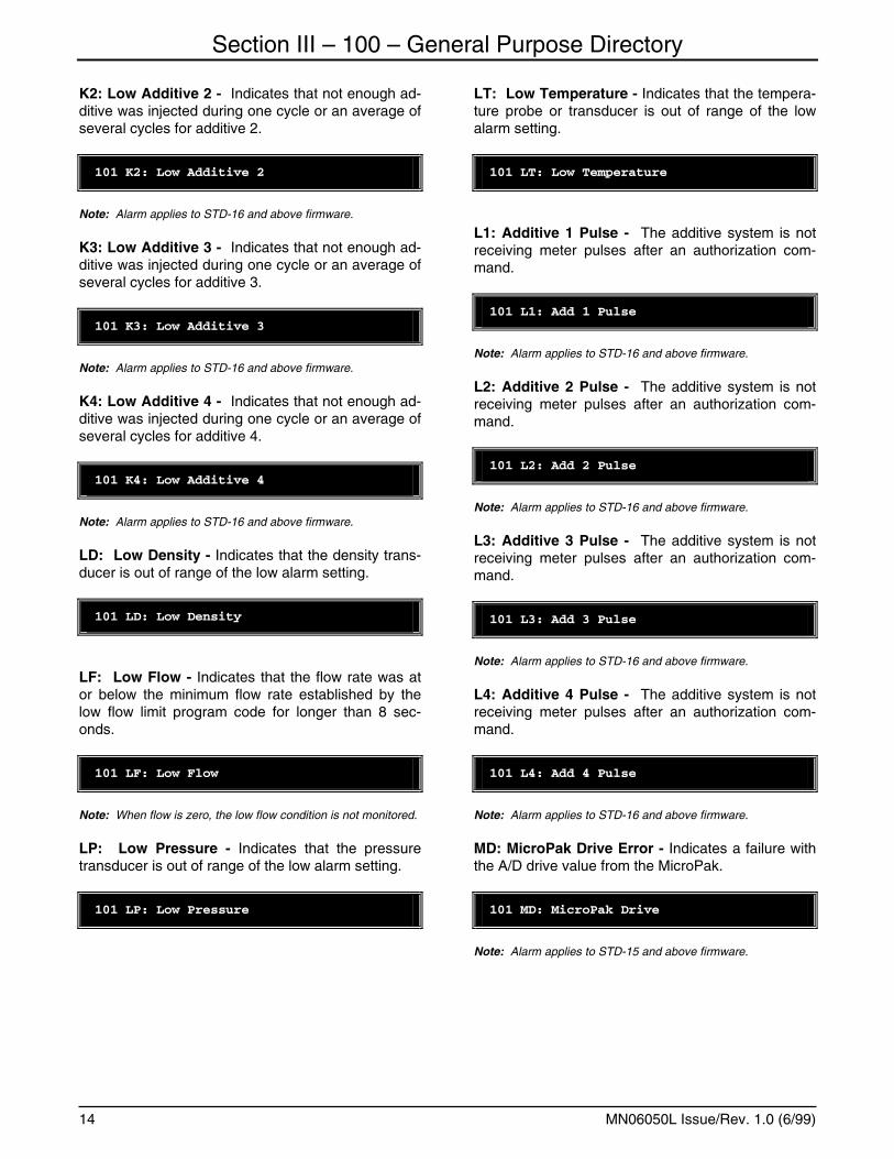
K2: Low Additive 2 - Indicates that not enough ad-ditive was injected during one cycle or an average of several cycles for additive 2.
101 K2: Low Additive 2
Note: Alarm applies to STD-16 and above firmware.
K3: Low Additive 3 - Indicates that not enough ad-ditive was injected during one cycle or an average of several cycles for additive 3.
101 K3: Low Additive 3
Note: Alarm applies to STD-16 and above firmware.
K4: Low Additive 4 - Indicates that not enough ad-ditive was injected during one cycle or an average of several cycles for additive 4.
101 K4: Low Additive 4
Note: Alarm applies to STD-16 and above firmware.
LD: Low Density - Indicates that the density trans-ducer is out of range of the low alarm setting.
101 LD: Low Density
LF: Low Flow - Indicates that the flow rate was at or below the minimum flow rate established by the low flow limit program code for longer than 8 sec-onds.
101 LF: Low Flow
Note: When flow is zero, the low flow condition is not monitored.
LP: Low Pressure - Indicates that the pressure transducer is out of range of the low alarm setting.
101 LP: Low Pressure
LT: Low Temperature - Indicates that the tempera-ture probe or transducer is out of range of the low alarm setting.
101 LT: Low Temperature
L1: Additive 1 Pulse - The additive system is not receiving meter pulses after an authorization com-mand.
101 L1: Add 1 Pulse
Note: Alarm applies to STD-16 and above firmware.
L2: Additive 2 Pulse - The additive system is not receiving meter pulses after an authorization com-mand.
101 L2: Add 2 Pulse
Note: Alarm applies to STD-16 and above firmware.
L3: Additive 3 Pulse - The additive system is not receiving meter pulses after an authorization com-mand.
101 L3: Add 3 Pulse
Note: Alarm applies to STD-16 and above firmware.
L4: Additive 4 Pulse - The additive system is not receiving meter pulses after an authorization com-mand.
101 L4: Add 4 Pulse
Note: Alarm applies to STD-16 and above firmware.
MD: MicroPak Drive Error - Indicates a failure with the A/D drive value from the MicroPak.
101 MD: MicroPak Drive
Note: Alarm applies to STD-15 and above firmware.
Section III – 100 – General Purpose Directory
MN06050L Issue/Rev. 1.0 (6/99) 15
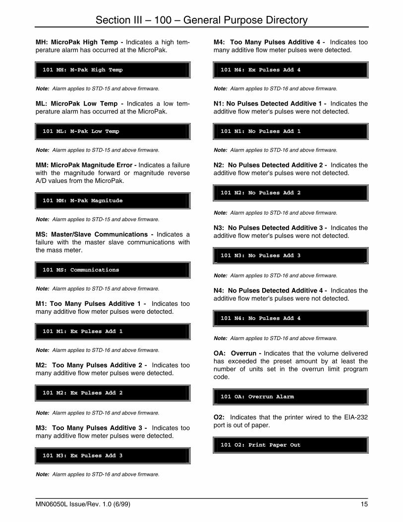
MH: MicroPak High Temp - Indicates a high tem-perature alarm has occurred at the MicroPak.
101 MH: M-Pak High Temp
Note: Alarm applies to STD-15 and above firmware.
ML: MicroPak Low Temp - Indicates a low tem-perature alarm has occurred at the MicroPak.
101 ML: M-Pak Low Temp
Note: Alarm applies to STD-15 and above firmware.
MM: MicroPak Magnitude Error - Indicates a failure with the magnitude forward or magnitude reverse A/D values from the MicroPak.
101 MM: M-Pak Magnitude
Note: Alarm applies to STD-15 and above firmware.
MS: Master/Slave Communications - Indicates a failure with the master slave communications with the mass meter.
101 MS: Communications
Note: Alarm applies to STD-15 and above firmware.
M1: Too Many Pulses Additive 1 - Indicates too many additive flow meter pulses were detected.
101 M1: Ex Pulses Add 1
Note: Alarm applies to STD-16 and above firmware.
M2: Too Many Pulses Additive 2 - Indicates too many additive flow meter pulses were detected.
101 M2: Ex Pulses Add 2
Note: Alarm applies to STD-16 and above firmware.
M3: Too Many Pulses Additive 3 - Indicates too many additive flow meter pulses were detected.
101 M3: Ex Pulses Add 3
Note: Alarm applies to STD-16 and above firmware.
M4: Too Many Pulses Additive 4 - Indicates too many additive flow meter pulses were detected.
101 M4: Ex Pulses Add 4
Note: Alarm applies to STD-16 and above firmware.
N1: No Pulses Detected Additive 1 - Indicates the additive flow meter's pulses were not detected.
101 N1: No Pulses Add 1
Note: Alarm applies to STD-16 and above firmware.
N2: No Pulses Detected Additive 2 - Indicates the additive flow meter's pulses were not detected.
101 N2: No Pulses Add 2
Note: Alarm applies to STD-16 and above firmware.
N3: No Pulses Detected Additive 3 - Indicates the additive flow meter's pulses were not detected.
101 N3: No Pulses Add 3
Note: Alarm applies to STD-16 and above firmware.
N4: No Pulses Detected Additive 4 - Indicates the additive flow meter's pulses were not detected.
101 N4: No Pulses Add 4
Note: Alarm applies to STD-16 and above firmware.
OA: Overrun - Indicates that the volume delivered has exceeded the preset amount by at least the number of units set in the overrun limit program code.
101 OA: Overrun Alarm
O2: Indicates that the printer wired to the EIA-232 port is out of paper.
101 O2: Print Paper Out
Section III – 100 – General Purpose Directory
MN06050L Issue/Rev. 1.0 (6/99) 16
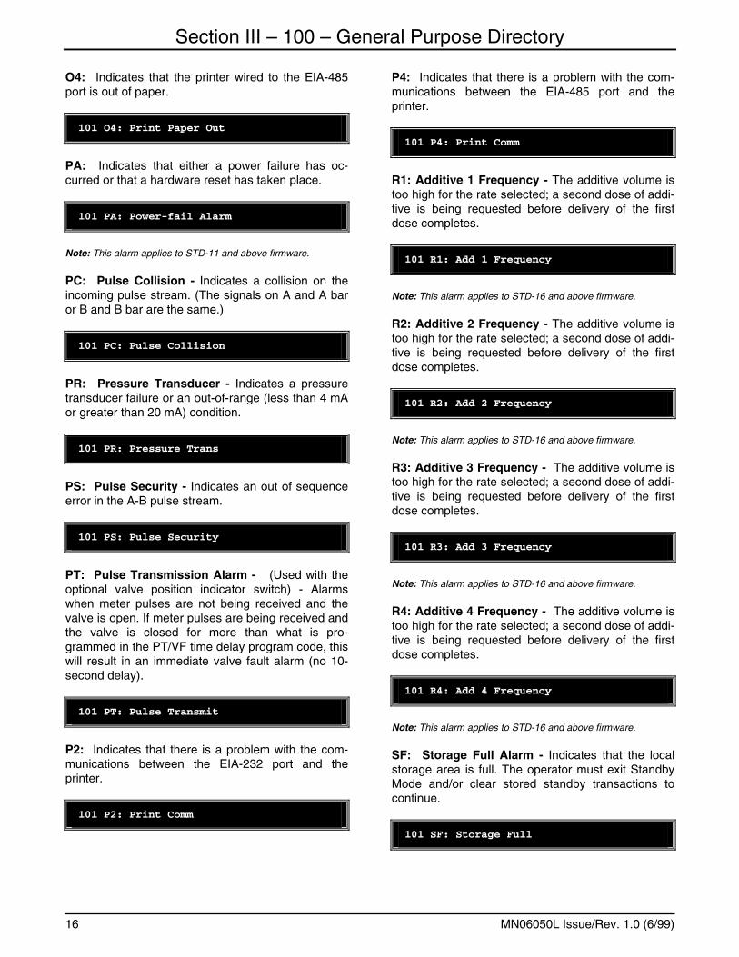
O4: Indicates that the printer wired to the EIA-485 port is out of paper.
101 O4: Print Paper Out
PA: Indicates that either a power failure has oc-curred or that a hardware reset has taken place.
101 PA: Power-fail Alarm
Note: This alarm applies to STD-11 and above firmware.
PC: Pulse Collision - Indicates a collision on the incoming pulse stream. (The signals on A and A bar or B and B bar are the same.)
101 PC: Pulse Collision
PR: Pressure Transducer - Indicates a pressure transducer failure or an out-of-range (less than 4 mA or greater than 20 mA) condition.
101 PR: Pressure Trans
PS: Pulse Security - Indicates an out of sequence error in the A-B pulse stream.
101 PS: Pulse Security
PT: Pulse Transmission Alarm - (Used with the optional valve position indicator switch) - Alarms when meter pulses are not being received and the valve is open. If meter pulses are being received and the valve is closed for more than what is pro-grammed in the PT/VF time delay program code, this will result in an immediate valve fault alarm (no 10-second delay).
101 PT: Pulse Transmit
P2: Indicates that there is a problem with the com-munications between the EIA-232 port and the printer.
101 P2: Print Comm
P4: Indicates that there is a problem with the com-munications between the EIA-485 port and the printer.
101 P4: Print Comm
R1: Additive 1 Frequency - The additive volume is too high for the rate selected; a second dose of addi-tive is being requested before delivery of the first dose completes.
101 R1: Add 1 Frequency
Note: This alarm applies to STD-16 and above firmware.
R2: Additive 2 Frequency - The additive volume is too high for the rate selected; a second dose of addi-tive is being requested before delivery of the first dose completes.
101 R2: Add 2 Frequency
Note: This alarm applies to STD-16 and above firmware.
R3: Additive 3 Frequency - The additive volume is too high for the rate selected; a second dose of addi-tive is being requested before delivery of the first dose completes.
101 R3: Add 3 Frequency
Note: This alarm applies to STD-16 and above firmware.
R4: Additive 4 Frequency - The additive volume is too high for the rate selected; a second dose of addi-tive is being requested before delivery of the first dose completes.
101 R4: Add 4 Frequency
Note: This alarm applies to STD-16 and above firmware.
SF: Storage Full Alarm - Indicates that the local storage area is full. The operator must exit Standby Mode and/or clear stored standby transactions to continue.
101 SF: Storage Full
Section III – 100 – General Purpose Directory
MN06050L Issue/Rev. 1.0 (6/99) 17
SP: Shared Printer - Indicates an output was at-tempted to the shared printer, but was unsuccessful because the shared printer remained busy longer than the programmed shared printer out alarm timer.
101 SP: Shared Printer
TK: Ticket Alarm - Indicates that a removal of the ticket from the local ticket printer was tried during a batch loading. When the alarm is received, press "PRINT" to clear the transaction.
101 TK: Ticket Alarm
TP: Temperature Probe - Indicates a short or open condition in the temperature probe circuit (main line probe).
101 TP: Temperature Probe
TT: Temperature Transducer - Indicates a tem-perature transducer failure or an out-of-range condi-tion. (Monitored when the 4-20 channel is selected as a temperature input).
101 TT: Temperature Trans
U1: Unauthorize Command Failed For Additive 1 - The unauthorize command failed at the end of the batch for additive 1. Authorization may have to be removed manually (by power cycling the additive subsystem) to prevent unwanted additive in subse-quent batches/transactions.
101 U1: Unauth Failed 1
Note: This alarm applies to STD-16 and above firmware.
U2: Unauthorize Command Failed For Additive 2 - The unauthorize command failed at the end of the batch for additive 2. Authorization may have to be removed manually (by power cycling the additive subsystem) to prevent unwanted additive in subse-quent batches/transactions.
101 U2: Unauth Failed 3
Note: This alarm applies to STD-16 and above firmware.
U3: Unauthorize Command Failed For Additive 3 - The unauthorize command failed at the end of the batch for additive 3. Authorization may have to be removed manually (by power cycling the additive subsystem) to prevent unwanted additive in subse-quent batches/transactions.
101 U3: Unauth Failed 3
Note: This alarm applies to STD-16 and above firmware.
U4: Unauthorize Command Failed For Additive 4 - The unauthorize command failed at the end of the batch for additive 4. Authorization may have to be removed manually (by power cycling the additive subsystem) to prevent unwanted additive in subse-quent batches/transactions.
101 U4: Unauth Failed 4
Note: This alarm applies to STD-16 and above firmware.
VF: Valve Fault - Indicates that the valve did not close within 10 seconds after receiving the signal to close. This alarm will close the alarm contact signal-ing the operator of the problem, if so programmed in code 143. This is the only alarm that will cause the alarm contact to close.
101 VF: Valve Fault
If any alarms were present, press "ENTER" to clear each alarm that appears. The clearing must be re-peated until "No Alarms Present" appears on the display.
Note: This action will clear the display, but if the fault is not cor-rected, the alarm will recur at the next operation.
101 No Alarms Present
Help Message
View the alarm status. Press "ENTER" to clear the alarm.
Section III – 100 – General Purpose Directory
MN06050L Issue/Rev. 1.0 (6/99) 18
102 - Run Mode Alarms This code allows the operator to view the alarms that have occurred during the most recent transaction. All alarms will be listed from left to right in the order that they occurred. They will be listed in this program code regardless of whether they have been cleared or are still present. Up to ten alarms may be listed; this number is further limited by the entry in the Run Mode alarm clearing option select. That is, if seven is entered as the limit that may be cleared, then no more than seven alarms will be listed here as more than seven alarms would cause the transaction to be ended.
1. If there were a temperature probe alarm, a ticket printer alarm, two excess high flow alarms and an overrun alarm (in that order), the display would be as follows:
102 TPTKHFHFOA
2. This program code is for viewing the alarm his-
tory only. Present alarms may be cleared under the alarm check program code.
Help Message
View all alarms encountered during the most recent transaction.
103 - Ready Mode Alarms This code allows the operator to view the alarms that have occurred and have been cleared in the Ready Mode since the last transaction. All alarms will be listed from left to right in the order in which they oc-curred. They will be listed in this program code re-gardless of whether they have been cleared. Up to ten alarms may be listed; this number is limited by the entry in the Run Mode alarm clearing selection. That is, if seven is entered as the limit that may be cleared, then no more than seven alarms will be listed here.
1. If there were a pulse transmission and a com-munication alarm (in that order) the display would be as follows:
103 PTCM
2. This program code is for viewing the alarm his-tory only.
Help Message
View all alarms cleared in the Ready Mode after the last transaction.
104 - Time Set A correction to the time may be made through this five-digit entry. This program code will be available in both meter positions programming menus, the entry is common to both positions. The first four numbers entered consist of two digits for the hour and two dig-its for the minutes. The last number entered will show military time or AM or PM for standard time.
0 - AM 1 - PM 2 - Military time
Help Message
Set the time in hours, minutes and AM, PM or mili-tary.
Fatal Warning
Fatal: The time entered is in error or has inconsistent format.
105 - Date Set A correction to the date may be made through this entry. This program code will be available in both meter positions programming menus, the entry is common to both positions. The format for date entry will be dependent on the time type entry. The six dig-its entered consist of two digits for the month, two digits for the day, and two digits for the year.
Time Type = Military then Date format = Day - Month - Year
Time Type = Standard then Date format = Month - Day - Year
105 03-12-98 Date
Help Message
Set the date in month, day and year (Std) or day, month and year (Mil).
Fatal Warning
Section III – 100 – General Purpose Directory
MN06050L Issue/Rev. 1.0 (6/99) 19
Fatal: The date entered is in error or has inconsistent format.
106 - Dynamic Display Time-out This two digit code will allow the operator to enter the amount of time in seconds that a dynamic display will remain displayed. The range of this program code will be 00 - 99 seconds where a zero entry will cause the dynamic display to remain until the "CLEAR" key is pressed.
106 10 Dynamic Time-out
Help Message
Enter the time in seconds that a dynamic display will remain displayed.
107 - Flashing Totals Display This program code allows the Raw, Gross, Gst, Net and Mass totals to be alternately displayed for five second periods while the AccuLoad II is in the Ready Mode (showing READY and the time).
Options available:
0 - Do not flash totals. 1 - Flash all totals. 2 - Flash only those totals that are used.
107 1 Flash All Totals
Help Message
Select flashing totals in the Ready Mode: none, all, or used only.
Fatal Warning
Fatal: Entry is out of specified range.
140 - Protection of Program Codes 180-189 This code will allow the operator to select whether the block of program codes (180 through 189) will be allowed to change under the Program Mode or the Weights and Measures Mode protection require-ments.
To select the protection for 180 through 189 block of program codes and to satisfy the Weights and
Measures Mode protection entry criteria the following options are available:
0 - Weights & Measures Protection
1 - Program Mode Protection
140 1 Program Entry
Help Message
Select the level of protection for program codes 180 through 189.
Fatal Warning
Fatal: Entry is out of specified range.
141 - Local Mode Alarm Clearing This one digit program code allows the operator to clear certain alarms (see below) while in the Ready and Run Modes of operation. The operator may se-lect a quantity of one to nine as the maximum num-ber of alarms that may be cleared in a single trans-action. When this option is selected, any applicable alarm received during the loading operation will at-tempt to shut down the flow. At this point, the opera-tor will have the option of clearing the alarm and con-tinuing with the load or ending the transaction. An entry of zero will disable the Ready and Run Modes alarm clearing.
If the number of alarms exceeds the programmed value, the alarm will not be clearable in the Ready or Run Modes. It must be cleared by gaining entry to the program menu and proceeding in the normal fashion. (See Alarm Check and Reset program code 101).
The current alarm(s) will be available in the program menu under the Alarm Check and Reset code. A his-tory of the alarm(s) detected during a transaction will be accessible in the transaction alarms program code 102. Also, a history of alarms cleared in the Ready Mode is available in the ready alarms pro-gram code 103. These are also available through the communication line.
141 4 Local Alarm Clear
Section III – 100 – General Purpose Directory
MN06050L Issue/Rev. 1.0 (6/99) 20
Help Message
Select local alarm clearing feature & number of tries to clear alarms.
Clearing of alarms in the Run Mode is accomplished as follows:
1. Wait for flow to come to a stop (if necessary). The following display will be alternating with the normal display when alarms may be cleared.
XX Alarm Press "Clear"
XX is the two-digit code for the present alarm.
2. Press "CLEAR" to clear the alarm to continue the transaction.
If the number of alarms in a single transaction has exceeded the limit, the local alarm clearing option is not selected, or the alarm is not one of those clear-able in this method, this display will not appear.
The display will read:
XX Alarm See Manager
The operator must then press "PRINT" to end the transaction. The display will then read:
XX Alarm Press "CLEAR"
The operator can then press "CLEAR" to clear the alarm. At this point the operator can go into program code 102 to see the alarms that occurred during the last transaction. Also program code 103 will register the last alarm that was cleared after the "PRINT" key was pressed.
All alarms except "DA" (Diagnostic Alarm) may be cleared in the Run Mode.
Note: If more than one of these alarms exist, they must each be cleared separately as they appear on the display.
142 - Decimal or Comma This one digit entry specifies whether a decimal or a comma is to be used on the display. The comma is normally used in the European market instead of the decimal point.
0 - Decimal
1 - Comma
142 0 Decimal
Help Message
Select either the use of decimals or commas for frac-tional numbers.
Fatal Warning
Fatal: Entry is out of specified range.
143 - Alarm Relay This one digit entry specifies how the alarm contact will operate.
0 - Alarm Relay on Value Fault Only 1 - Alarm Relay on Any Fault 2 - No Alarm Relay on Any Fault
143 0 Alarm Relay On VF
Help Message
Select whether the alarm relay will be set when a VF alarm occurs, any alarm occurs, or will remain off.
Fatal Warning
Fatal: Entry is out of specified range.
144 - RUN/READY Initialization This code allows the user to initialize all of the dis-plays used in the RUN/READY Mode of operation. Two possible selections are available:
0 - English 1 - Portuguese
144 0 English
Section III – 100 – General Purpose Directory
MN06050L Issue/Rev. 1.0 (6/99) 21
Help Message Select the desired initialization setting, press "EN-TER" to initialize. 0 = English, 1 = Portuguese.
Fatal Warning Fatal: The other meter position must be in the READY or PROGRAM Mode of operation.
145 - Ready/Run Mode Clearable Alarms Se-lection This code allows the operator to program the alarms that may be cleared in the Ready/Run Mode of op-eration. Each alarm has an entry number that has to be entered to display the alarm (see the table be-low). Once the alarm entry number has been entered and the alarm displayed, a 0 or a 1 can be entered to indicate if the alarm can be cleared or not cleared (0 = clearable, 1 = not clearable).
Note: 1. Diagnostic alarms are never clearable in the Ready/Run
Mode. 2. If program code 141 is programmed 0 indicating that no alarms can be cleared in the Ready/Run Mode then "No Alarm Clearing" will be displayed in this code and no entries will be al-lowed. 3. All alarms are initialized at the factory to 0 (clearable).
Programming the clearable alarms is accomplished by the following procedure:
1. The display will appear as follows:
145 Run Clearable Alarms
2. Enter the table number of the alarm that is to be
changed (i.e., 45 Zero Flow).
145 Run Clearable Alar35
3. Press "ENTER" to display the alarm.
0 ZF: Zero Flow Alarm
4. To change the alarm from clearable to not clear-
able, enter a "1".
0 ZF: Zero Flow Alarm 1
5. Press "ENTER".
1 ZF: Zero Flow Alarm
After the alarms have been programmed to fit the application the settings should be recorded in the Appendix of the Programming Workbook (AB06029) for future reference.
Help Message Select which alarms may be cleared in the Run and Ready Modes. Note: This code applies to STD-13 and above firmware.
146 – Second Alarm Output A second alarm output is also available. This output is shared with the additive injector 3 output; when the third injector (piston type) is not programmed for use, the relay will function as the Alarm 2 output. The second alarm is configurable to be activated only on the alarms selected by the user. Program code 146 has been added to allow the programming of the second alarm output. (0 = doesn't affect the output; 1 = activates the output.)
Note: 1. All alarms are initialized at the factory to 0 (will not activate the alarm relay. 2. This alarm output will not be available if the additive injector #3 pulse output is programmed for use.
Programming the second alarm output is accom-plished by the following procedure:
1. The display will appear as follows:
146 Alarm 2 Selections
2. Enter the table number of the alarm that is to be changed (i.e., 45 Zero Flow).
146 Alarm 2 Selections45
3. Press "ENTER" to display the alarm.
0 ZF: Zero Flow Alarm
4. To change the alarm from not affecting the out-put to activating the output, enter a "1".
0 ZF: Zero Flow Alarm
5. Press "ENTER."
ZF1: Zero Flow Alarm
Note: This code applies to STD-23 and above firmware.
Section III – 100 – General Purpose Directory
MN06050L Issue/Rev. 1.0 (6/99) 22
Section III – 100 – General Purpose Directory
MN06050L Issue/Rev. 1.0 (6/99) 23
Entry Alarm
1 CM: Communications
2 TK: Ticket Alarm
3 HT: High Temperature
4 LT: Low Temperature
5 TP: Temperature Probe
6 HF: Excess High Flow
7 OA: Overrun
8 LF: Low Flow
9 PT: Pulse Transmission Alarm
10 VF: Valve Fault
11 BP: Back Pressure
12 HP: High Pressure
13 LP: Low Pressure
14 PR: Pressure Transducer
15 PC: Pulse Collision
16 PS: Pulse Security
17 DP: Down Pulse Error Alarm
18 HD: High Density Alarm
19 LD: Low Density Alarm
20 DR: Density Transducer Alarm
21 TT: Temperature Transducer Alarm
22 SP: Shared Printer Alarm
23 SF: Local Storage Full Alarm
24 F1: Additive Feedback 1 Alarm
25 F2: Additive Feedback 2 Alarm
26 F3: Additive Feedback 3 Alarm
27 F4: Additive Feedback 4 Alarm
28 H2: Set at Entry 755 (232 Printer Hardware Alarm) Note: This applies to STD-14 and above firmware.
29 O2: Set at Entry 755 (232 Printer Paper Out) Note: This applies to STD-14 and above firmware.
30 A2: Set at Entry 755 (232 Printer Cover Open Alarm) Note: This applies to STD-14 and above firmware.
31 P2: Set at Entry 755 (232 Printer Comm Alarm) Note: This applies to STD-14 and above firmware.
Section III – 100 – General Purpose Directory
MN06050L Issue/Rev. 1.0 (6/99) 24
32 B2: Set at Entry 755 (232 Printer Buffer Overflow) Note: This applies to STD-14 and above firmware.
33 D2: Set at Entry 755 (232 Printer Deselected Alarm) Note: This applies to STD-14 and above firmware.
34 E2: Set at Entry 755 (232 General Printer Error) Note: This applies to STD-14 and above firmware.
35 I2: Set at Entry 755 (232 Printer Not Responding) Note: This applies to STD-14 and above firmware.
36 H4: Set at Entry 755 (485 Printer Hardware Alarm) Note: This applies to STD-14 and above firmware.
37 O4: Set at Entry 755 (485 Printer Paper Out Alarm) Note: This applies to STD-14 and above firmware.
38 A4: Set at Entry 755 (485 Printer Cover Open Alarm) Note: This applies to STD-14 and above firmware.
39 D4: Set at Entry 755 (485 Printer Deselected Alarm) Note: This applies to STD-14 and above firmware.
40 B4: Set at Entry 755 (485 Printer Buffer Overflow) Note: This applies to STD-14 and above firmware.
41 P4: Set at Entry 755 (485 Printer Comm Alarm) Note: This applies to STD-14 and above firmware.
42 E4: Set at Entry 755 (485 Printer General Alarm) Note: This applies to STD-14 and above firmware.
43 I4: Set at Entry 755 (485 Printer Not Responding) Note: This applies to STD-14 and above firmware.
44 PA: Set at entry 184 (Power-fail Alarm) Note: This applies to STD-14 and above firmware.
45 ZF: Zero Flow Alarm
46 MS: Communications Note: This applies to STD-15 and above firmware.
47 MD: MicroPak Drive Note: This applies to STD-15 and above firmware.
48 MM: M-Pak Magnitude Note: This applies to STD-15 and above firmware.
49 ML: M-Pak Low Temp Note: This applies to STD-15 and above firmware.
50 MH: M-Pak High Temp Note: This applies to STD-15 and above firmware.
51 AC: Additive Communications Note: This applies to STD-16 and above firmware.
52 IA: Injector Alarm Note: This applies to STD-16 and above firmware.
53 R1: Additive 1 Frequency Note: This applies to STD-16 and above firmware.
54 R2: Additive 2 Frequency Note: This applies to STD-16 and above firmware.
Section III – 100 – General Purpose Directory
MN06050L Issue/Rev. 1.0 (6/99) 25
55 R3: Additive 3 Frequency Note: This applies to STD-16 and above firmware.
56 R4: Additive 4 Frequency Note: This applies to STD-16 and above firmware.
57 L1: Additive 1 Pulse Note: This applies to STD-16 and above firmware.
58 L2: Additive 2 Pulse Note: This applies to STD-16 and above firmware.
59 L3: Additive 3 Pulse Note: This applies to STD-16 and above firmware.
60 L4: Additive 4 Pulse Note: This applies to STD-16 and above firmware.
61 N1: No Pulses Detected Additive 1 Note: This applies to STD-16 and above firmware.
62 N2: No Pulses Detected Additive 2 Note: This applies to STD-16 and above firmware.
63 N3: No Pulses Detected Additive 3 Note: This applies to STD-16 and above firmware.
64 N4: No Pulses Detected Additive 4 Note: This applies to STD-16 and above firmware.
65 M1: Too Many Pulses Additive 1 Note: This applies to STD-16 and above firmware.
66 M2: Too Many Pulses Additive 2 Note: This applies to STD-16 and above firmware.
67 M3: Too Many Pulses Additive 3 Note: This applies to STD-16 and above firmware.
68 M4: Too Many Pulses Additive 4 Note: This applies to STD-16 and above firmware.
69 K1: Low Additive 1 Note: This applies to STD-16 and above firmware.
70 K2: Low Additive 2 Note: This applies to STD-16 and above firmware.
71 K3: Low Additive 3 Note: This applies to STD-16 and above firmware.
72 K4: Low Additive 4 Note: This applies to STD-16 and above firmware.
73 U1: Unauthorize Command Failed, Additive 1 Note: This applies to STD-16 and above firmware.
74 U2: Unauthorize Command Failed, Additive 2 Note: This applies to STD-16 and above firmware.
75 U3: Unauthorize Command Failed, Additive 3 Note: This applies to STD-16 and above firmware.
76 U4: Unauthorize Command Failed, Additive 4 Note: This applies to STD-16 and above firmware.
Section III – 100 – General Purpose Directory
MN06050L Issue/Rev. 1.0 (6/99) 26
180 - Programming Access Code This four-digit number permits entry into the Accu-Load II's program code menu. The access code may be changed under Program Mode security or Weights and Measures Mode security, depending on the entry in program code 140. This access code must be entered before entry of the AccuLoad II's program code menu for any security level.
180 0000
181 - Product Message Select This code will allow a nine-character entry message to accompany the "Ready" display and serve as a meter or product identifier. The data entry will allow the following characters to be selected as part of the prompt:
• A B C D E F G H I J K L M N O P Q R S T U V W X Y Z
• a b c d e f g h i j k l m n o p q r s t u v w x y z • 0 1 2 3 4 5 6 7 8 9 • + ! " # $ % & ` ( ) , - . / : ; < = > @ [ \ ^ _ ' {l} ° ? *
space
181 Unleaded = Prod Msg
Help Message
Alphanumeric product identifier displayed in the Ready Mode.
182 - Auto Reset Time This two-digit code defines the amount of time that the AccuLoad II will remain in the Program Mode. The clock starts after each keystroke and if another keystroke is not made in the time set in this code, the unit will revert to the Ready Mode. The range of this entry is 01 to 99 minutes.
182 05 Auto Reset Time
Note: An entry of 00 will disable this feature.
Help Message
Enter the time, in minutes, that the AccuLoad will re-set to the Ready Mode if no operator activity is de-tected for the consecutive time value programmed.
183 - Run & Ready Mode Customized Dis-play This program code is used to program all of the dis-plays used in the RUN/READY Mode of operation. To program a display the operator enters the number of the display that is to be changed. When the par-ticular display appears, the keypad is then used to advance to each character to be changed and also to increment or decrement the character. The data entry will allow the following characters to be se-lected as part of the message:
• A B C D E F G H I J K L M N O P Q R S T U V W X Y Z
• a b c d e f g h i j k l m n o p q r s t u v w x y z • 0 1 2 3 4 5 6 7 8 9 • + ! " # $ % & ' ( ) , - . / : ; < = > @ [ \ ^ _ {l} ° ? *
space 1. To program the Run & Ready Mode messages,
Enter the number of the display you want to change. Numbers and English default messages are in the table below.
183 Customize Display 7
2. Press "ENTER" to display the message that is
associated with the table number:
Report Pending to Print
3. Change the message as required for the applica-
tion following the steps described in the Operator Guide (MN06041) in the Section on Program Mode.
4. Proceed to the next message as described in the above steps.
Note: The customized displays are not meter dependent, the dis-plays are the same for each meter side. The displays can be cus-tomized from either meter side.
Note: The opposite meter must be in the READY or PROGRAM Mode in order to use the display customizing feature.
Help Message
Use the keypad in order to customize this display. Press the "Enter" key to store into memory.
Fatal Warning
Fatal: The other meter position must be in the READY or PROGRAM Mode of operation.
Section III – 100 – General Purpose Directory
MN06050L Issue/Rev. 1.0 (6/99) 27
STD Display Customization Entry Table
Entry number Entry description Output length
* 001 Alarm - See Manager 22
* 002 Alarm Press "Clear" 22
* 003 Alarm Press "Print" 22
* 004 Alarm - Remove Ticket 22
005 ** Remove Ticket ** 24
006 Please Wait 24
007 Report Pending To Print 24
008 No Local Start Allowed 24
009 Meter Position Not Used 24
010 Press Clear To Continue. 24
011 Press Start To Continue 24
012 ** Error Press Clear ** 24
** 013 Ready 6
** 014 Restart In 11
** 015 Valve Delay = 14
016 ** Not Authorized ** 24
017 Flow = 7
018 Flow* = 7
019 /Min 4
020 /Hr 3
** 021 Temperature = 15
** 022 Ref Density 12
** 023 Rel Density = 18
** 024 Meter Factor = 18
025 Raw Transaction 15
026 Grs Transaction 15
027 Gst Transaction 15
028 Net Transaction 15
029 Mas Transaction 15
** 030 Inj1 Trans 14
Section III – 100 – General Purpose Directory
MN06050L Issue/Rev. 1.0 (6/99) 28
Entry number Entry description Output length
** 031 Inj2 Trans 14
** 032 Inj3 Trans 14
** 033 Inj4 Trans 14
034 Inj1 Total 10
035 Inj2 Total 10
036 Inj3 Total 10
037 Inj4 Total 10
038 Density 7
039 Totals 6
** 040 Valve Requested 17
041 Open 4
042 Closed 6
043 Lock 4
** 044 Load Avg Temp = 15
** 045 Load Avg Mfac = 18
** 046 Load Avg Pres = 19
** 047 Load Avg Dens = 18
048 Off 3
049 On 3
050 Secs. 5
051 Select Injector# 16
052 Injectors On = # 16
053 No Injectors Selected 24
054 Inj 3
055 Prog 4
056 Cal 3
057 Raw 3
058 Grs 3
059 Gst 3
060 Net 3
061 Mass 4
Section III – 100 – General Purpose Directory
MN06050L Issue/Rev. 1.0 (6/99) 29
Entry number Entry description Output length
062 Temp 7
063 Gross 5
064, 065, 066 Preset batch volume exceeds the maximum permitted. 3 * 24
067, 068, 069 Preset batch volume is below the minimum required. 3 * 24
070, 071, 072 The preset volume will cause the max transaction volume to be exceeded.
3 * 24
Note: * An entry number flagged with an asterisk (*) designates that the entry description should have a leading space in the message. This will allow for display concatenation without running words together.
Note: ** An entry number flagged with two asterisks (**) designates that the entry description should have a trailing space in the message. This will allow for display concatenation without running words together.
Note: The output length of each table entry signifies the maximum number of characters allowable for that particular message even though the default message may not take up all spaces allowed.
Note: The entry numbers 064, 065, and 066 are 24 character messages each. They are concatenated together to form a 72-character scrolling message. This is also true of the table entry group of 067, 068 and 069, and also the group of 070, 071, and 072.
Section III – 100 – General Purpose Directory
MN06050L Issue/Rev. 1.0 (6/99) 30
184 - Power-fail Alarm This code allows the operator to program the Accu-Load II as to how to respond when a power failure or hardware reset occurs. Also if the operator programs the unit to alarm in the case of a power failure or hardware reset he can also choose how that alarm is allowed to be cleared. Three possible selections are available:
0 - No Power-fail Alarm.
1 - Power-fail Alarm Only. Alarm cannot be cleared through the Run or Ready Mode of operation but can be cleared through the Program Mode or Communications.
2 - Power-fail Alarm Local. Alarm can be cleared locally in the Run and Ready Mode of operation if local alarm clearing is enabled in program code 143. The alarm can also be cleared through the Program Mode of operation and through Communications.
Note: This code is common to both preset positions, therefore when changed in the Program Mode of either position changes both.
184 0 Power Alarm Only
Help Message
Enter whether to Disable an Alarm on Power-fail (0), Enable without Local Alarm Clearing (1), or Enable with Local Alarm Clearing (2).
Fatal Warning
Fatal: The other meter position must be in the Ready or Program Mode of operation.
Note: This code applies to STD-11 and above firmware.
190 - Meter Position Disable The AccuLoad II will contain the necessary software and hardware to operate two meter positions. At times this may be confusing to an operator if only one of the meter positions is currently connected and operating. For this reason, a program code will be added to disable the meter position not currently connected or in use. This program code will be under the High-Security Mode and when selected the me-ter not in use will constantly display the following message: "Meter Position Not Used."
Note: If the option for two meter positions is not installed, only one of the meter positions may be enabled at a time.
This one-digit number permits the AccuLoad II's me-ter position to be enabled or disabled. The entry will take effect on exit from the Programming Mode. The only activity allowed for the meter position disabled will be entry into its Program Mode to enable that meter position.
0 - Meter Enabled 1 - Meter Disabled
190 0 Meter Enabled
Note: Programming this code requires high-security jumpers on TP9 and TP10 - See Section 2 for details.)
Help Message
This meter position disabled from all functions except Program Mode.
Fatal Warning
Fatal: Entry is out of specified range.
Warning
Warning: The other meter position is currently en-abled.
Warning: The other meter position is currently dis-abled.
Section IV – 200 – Flow Control Directory
MN06050L Issue/Rev. 1.0 (6/99) 31
201 – Excess Flow Rate Commonly required on LPG loading systems, this two digit entry sets the maximum percentage by which the flow rate can exceed the high flow rate en-try without alarming. This two digit entry must be greater than the flow tolerance entry (program code 208), except when a value of zero is entered to dis-able excess high flow alarm checking. The excess rate is entered as a percentage of the first high flow rate.
201 15% Excess Flow
Note: A "00" entry disables the excess high flow alarm.
Help Message
Enter the highest flow rate allowed in % above the high flow rate.
Warning
Warning: A zero entry will disable this high flow alarm feature.
Warning: Entry is less than or equal to the flow toler-ance entry.
202 - Minimum Flow Rate This three-digit entry defines the lowest programmed (final stage) flow rate.
202 100 Min Flow Rate
Help Message
Enter the minimum flow rate for digital valve control operation.
203 - Valve Type This one-digit entry defines the type of valve to be controlled. There are two types: digital under which complete control can be accomplished, and two-stage which can only start, ramp down and close.
Note: If AccuLoad II is controlling flow with a two-stage valve, no alarm is given and flow is not halted if the pressure drops below the programmed limit which is determined by the vapor pressure and differential pressure. Therefore the differential pressure fea-ture should not be used with a two-stage valve.
0 - Digital flow control valve such as Smith 210 or 215.
1 - Two-stage control valve such as Smith 296 or 299.
203 0 Digital Valve
Help Message
Select the type of valve operation used: digital, two-stage.
Fatal Warning
Fatal: Entry is out of specified range.
204 - Low Flow Start Volume (Digital Valve) This four-digit entry shows the volume to be deliv-ered during low flow start.
204 0040 Low Flow Amount
Note: Low flow start, (if programmed in), will always be initiated from a zero flow condition. It will be initiated for the low flow start volume selected if the low flow rate is less than the desired flow. Otherwise, the desired flow will take priority.
"0000" disables the low flow start option.
Help Message
Enter the volume for delivery during low flow start.
205 - Low Flow Start Flow Rate (Digital Valve This four-digit entry designates the flow rate during low flow start.
205 0200 Low Flow Rate
Help Message
Enter the flow rate during low flow start operation.
Warning
Warning: A zero entry will not allow the valve to open at start.
Section IV – 200 – Flow Control Directory
MN06050L Issue/Rev. 1.0 (6/99) 32
206 - Zero Flow Timer This two-digit entry allows the operator to select the amount of time (in seconds) that the AccuLoad II is to ignore zero flow before going into a wait state. Once in this state, the "START" button must again be pressed to start the transaction. During this wait state the operator may cancel the current transaction or start a new batch if in the middle of a transaction. The range of this entry will be 01 through 99 sec-onds.
Conditions under which zero flow timer will be used:
1) Entries required.
a) A non-zero entry in the zero flow timer pro-gram code.
2) Operational requirements for the zero flow timer to be used.
a) The zero flow timer will be used immediately after start button is pressed and immediately after any permissive delays are cleared.
b) The zero flow timer will be used before:
i) An operator requested stop. ii) Normal batch termination.
3) Conditions under which zero flow timer will not be used:
a) After:
i) Operator requested stop or alarm condi-tion.
ii) Normal batch termination. iii) Improper program code entries. iv) If the zero flow condition results in a
pulse transmission situation (i.e., valve open and zero flow), and security is pro-grammed and the programmed PT/VF delay is less than the zero flow timer de-lay programmed. Under these conditions a PT/VF alarm would be recorded.
206 05 Sec Zero Q Timer
Note: "00" disables this option.
Help Message
Enter time in seconds. Zero flow is ignored before valve closure.
207 - High Flow Rate Select This code sets the high flow rate at which the valve will be controlled. The range of this entry is 0000 to 9999 flow units. This four digit program code defines for the:
Digital Valve - The normal maximum flow rate dur-ing loading being controlled by AccuLoad II.
Two-stage - This value, in combination with the ex-cess high flow value, determine the point at which a high flow alarm is triggered.
207 0600 High Flow Rate
Help Message
Enter the first high flow rate for digital valve control operation.
Warning
Warning: A zero entry will not allow the valve to open at start.
208 - Flow Tolerance This one digit entry designates the percentage of first high flow rate that any preprogrammed flow rate is permitted to vary from its programmed value without a valve correction signal from the AccuLoad II.
208 9% Flow Tolerance
Example:
First high flow rate programmed at 600 GPM Flow Tolerance 9%
All flow rates can vary 54 GPM (600 GPM X 9% = 54 GPM) without a valve correction signal from the Ac-cuLoad II.
Help Message
Enter desired flow rate tolerance in % of 1st high flow rate.
Section IV – 200 – Flow Control Directory
MN06050L Issue/Rev. 1.0 (6/99) 33
209 - Second High Flow Rate This four digit entry defines a second high flow rate which is selectable by an AC contact input. This pro-gram code is not used when a two-stage valve has been selected. The range of this entry is 0001 to 9999 flow units. If zero "0000" is entered, second high flow is disabled and the AC contact input may be used as a status input for the communications. This flow rate would be typically selected for smaller trucks.
209 0400 2nd High Flow
Note: "0000" disables the second high flow rate.
Help Message
Enter the second high flow rate for digital valve con-trol operation.
Warning
Warning: A zero entry will not allow the valve to open at start.
Critical: Conflict in use of contacts.
Note: This critical message shows that the 1st/2nd high flow switch is programmed for additive feedback input.
210 - First Trip Volume This four digit entry designates the preset volume remaining on the line when flow slow-down begins. This program code is for both digital and two-stage valves. The range of this entry is 0000 to 9999 units.
210 0040 1st Trip Point
Help Message
Enter the preset volume remaining before flow slow-down occurs.
211 - Final (Second) Trip Volume This three-digit entry defines the preset volume (in tenth of volume units) remaining at the final valve closure signal for the line.
211 01.5 2nd Trip Point
Help Message
Enter the preset volume remaining before valve clo-sure occurs.
212 - Final (Second) Trip Auto Adjust Limit This one digit entry defines the number of batches that are to be included in the average used to calcu-late the final trip adjustment. The range for this code is 1 to 9.
Note: The batch volumes must be above the 1st trip volume.
212 3 Auto Adjust Range
After the automatic adjustment has been completed this code will then read:
212 3 Auto Adjust Done
Note: "0" disables this final trip auto adjust.
If using the auto adjust to adjust the final stage trip point, program code 211 should be set to 00.0 for best results.
If for some reason the system parameters change and the final trip point needs adjusted, the operator must get into the Program Mode and reset this code to again automatically adjust the final stage trip point.
Help Message
Enter amount of batches to average for auto 2nd trip valve adjustment.
213 - Overrun Alarm Limit This two-digit entry defines the number of whole units required to trigger the overrun alarm. This value is preset to 05 units when shipped from the factory. The range of this entry is 01 to 99 units.
213 05 Overrun Limit
Note: "00" disables the overrun alarm limit.
Section IV – 200 – Flow Control Directory
MN06050L Issue/Rev. 1.0 (6/99) 34
Help Message
Enter number of units delivered over preset amount before alarm occurs.
Warning
Warning: A zero entry will disable this overrun alarm feature.
214 - Low Flow Alarm Limit This three-digit entry defines the set point in units per minute for the low flow alarm. The low flow alarm will be triggered whenever a flow rate is equal to or lower than the limit set and is maintained for eight sec-onds. The low flow alarm is not triggered in cases where there is no flow. The range of this entry is 001 to 999 flow units.
214 100 Low Flow Limit
Note: "000" disables the low flow alarm limit.
Help Message
Enter the minimum flow rate allowed without a low flow alarm.
Warning
Warning: A zero entry will disable this low flow alarm feature.
215 - Start After Stop Delay This three-digit entry allows a programmable delay (in seconds) for a start to occur after a stop was initi-ated in the middle of a batch. This delay will start immediately after the "STOP" key is pressed and flow goes to zero. The message
215 xxxx Restart in yyy
will be shown when the delay starts where xxxx = volume loaded and yyy = time in seconds. The "START" key may be pressed when the counter goes to zero and the display shows:
215 Press Start to Continue
Any attempt to restart before the countdown has ex-pired will be ignored. The countdown may be can-celed by pressing "SET" or "PRINT" or by removing the ticket from the load printer. The range of this en-try is 000 to 999 seconds.
Help Message
Enter the time in seconds to delay a start after stop in midload.
216 - Pump Relay Time Delay This two-digit entry will allow the operator to select a pump relay delay to off time in seconds. At any time during a normal or operator requested stop, the pump relay will be delayed by the programmed value in seconds before turning off. This delay will be over-ridden in an alarm condition (i.e., no delay to off). The range of this entry will be 00 to 99 seconds de-lay to off.
216 15 Sec Pump Delay
Help Message
Enter delay time in seconds to open the pump relay contact after stop.
217 - Valve Delay to Open This two-digit program code allows setting of a time delay (in seconds) before the valve will be com-manded to open after the pump relay is closed. This will allow the pump to pressurize the line, allowing for better valve response. The range of this entry is 01 to 99 seconds. For example, if the valve delay entry were set to 05 seconds when the start button was pressed, the pump relay would be commanded to close. Five seconds later the valve would be com-manded to open.
The AccuLoad II is not considered released until the valve delay time-out period has elapsed.
217 05 Sec Valve Delay
Note: An entry of 00 will disable the feature. Also the delay pro-grammed in the Zero Flow Timer, program code (206), will not be started until the valve delay is over.
Section IV – 200 – Flow Control Directory
MN06050L Issue/Rev. 1.0 (6/99) 35
Help Message
Enter delay time in seconds to open the valve after start.
218 - PT/VF Time Delay Setting This two-digit program code allows setting of a time delay (in seconds) before a Pulse Transmis-sion/Valve Fault (PT/VF) alarm occurs from the time that the condition exists. The range of this entry is 01 to 99 seconds.
218 10 Sec PT/VF Delay
Note: A "00" entry time delay is invalid.
Help Message
Enter the time delay in seconds allowed before a PT and VF alarm occurs.
Fatal Warning
Fatal: This program code entry must not be zero.
219 - Zero Flow Alarm This one-digit entry allows the operator to either en-able or disable the zero flow alarm. If the zero flow alarm is enabled (1) an alarm will be generated when the zero flow timer expires (time set in code 206). If the zero flow alarm is disabled (0) an alarm will not be generated if the zero flow timer expires.
0 – Zero Flow Alarm Disabled 1 – Zero Flow Alarm Enabled
219 1 Yes Zero Flow Alarm
Help Message
Enable/disable the zero flow alarm.
Fatal Warning
Fatal: Entry is out of specified range.
Note: This code applies to STD-13 and above firmware.
240 - Protection of Program Codes 280-289 This code will allow the operator to select whether the block of program codes (280 through 289) will be allowed to change under the Program Mode or the Weights and Measures Mode protection require-ments.
To select the protection for 280 through 289 block of program codes and to satisfy the Weights and Measures Mode protection entry criteria the following options are available:
Select the level of protection for program codes 280 through 289.
Fatal Warning
Fatal: Entry is out of specified range.
241 - Valve Security Select This one-digit entry specifies whether pulse trans-mission security is to be used. This option is in-tended for use with a valve containing a valve stem switch that provides an open or close indication.
0 - No Valve Security 1 - Yes Valve Security
Help Message
Select pulse transmission security using the valve stem switch.
Fatal Warning
Fatal: Entry is out of specified range.
Section V – 300 – Volume Accuracy Directory
MN06050L Issue/Rev. 1.0 (6/99) 36
301 - Transaction Control Select This one-digit entry defines the means of a transac-tion end and/or start.
0 - Local: For transactions that will be author-ized and terminated by a locally mounted se-rial printer (e.g., Load Printer): The "PRINT" key is disabled. The ticket printer tray switch is used to end the transaction.
1 - Print: For transactions that may be remotely authorized and terminated by the "PRINT" key: The ticket printer tray switch is ignored. The "PRINT" key is used to end the transac-tion.
2 - Remote: For transactions that will be au-thorized and terminated remotely (i.e., through communications): The "PRINT" key is disabled and the ticket printer tray switch is ignored.
3 - * Master Reset CT: For transactions that will be authorized and terminated by a master reset input: The "PRINT" key is disabled. The ticket printer tray input is used to author-ize and end the transaction and also clears the transaction totals.
4 - * Master Reset no CT: For transactions that will be authorized and terminated by a mas-ter reset input: The "PRINT" key is disabled. The ticket printer tray input is used to author-ize and end the transaction.
Note: If the print or local method is selected, the transaction may still be remotely authorized or terminated.
301 1 Print Key
Caution: If the remote option is selected and no communication absence alarms are pro-grammed, there is potential for a problem. Since the "PRINT" key is disabled in the Remote Mode, transactions can only be ended via communica-tions. If communications becomes inoperative under these conditions, the AccuLoad II will be in a deadlock condition. This deadlock can only be cleared by cycling power which will enable the "PRINT" key for a one-time use only (unless programmed otherwise).
Note: This program code will be overridden if the AccuLoad II goes into any condition under which a communications alarm is generated or the Standby Mode is entered. It will come back into force when the AccuLoad II communications is restored.
Help Message
Select method of transaction control: master reset without transaction clearing (CT), master reset with transaction clearing, remote, local, print.
Warning (If Remote is selected)
Critical: This selection requires poll & authorize or remote control communications.
Fatal Warning
Fatal: Entry is out of specified range.
* Rev. 3 firmware and above.
302 - Maximum Preset Volume This five-digit entry establishes the largest volume that can be preset. An error message appears; "Pre-set batch volume exceeds the maximum permitted. PRESS "CLEAR" TO CONTINUE", will be displayed on any attempt to start a batch with more than the maximum preset value. The range of this entry will be 00001 - 99999 units.
302 09999 Maximum Preset
Note: "00000" disables the maximum preset volume.
Help Message
Enter the maximum preset volume allowed for any batch.
303 - Minimum Preset Volume This five-digit entry will allow for the setting of the minimum preset amount. The range of this entry will be 00001 - 99999 units. An error message, "Preset batch volume is below the minimum required" is dis-played. PRESS "CLEAR" TO CONTINUE", will be displayed on any attempt to start a batch with less than the minimum preset value.
303 00500 Minimum Preset
Note: "00000" disables the minimum preset volume.
Section V – 300 – Volume Accuracy Directory
MN06050L Issue/Rev. 1.0 (6/99) 37
Help Message
Enter the minimum preset volume allowed for any batch.
304 - Auto Preset This code will allow the operator to select the Auto Preset Mode of operation for the AccuLoad II. In the Auto Preset Mode, the maximum preset program code (302) entry is used as the preset amount in the Run Mode in place of a manually entered amount.
0 - No Auto Preset 1 - Yes Auto Preset
304 0 No Auto Preset
Help Message
Select auto preset when a fixed preset value is al-ways desired.
Fatal Warning
Fatal: Entry is out of specified range.
305 - Blank Downcounter This code provides a blank downcounter option. The use of this option will disable the displaying of the downcounter in the Run Mode while dispensing the product.
0 - Downcounter Yes 1 - Downcounter No
Note: This option will have no effect while the AccuLoad II is in the Proving Mode.
305 0 Downcounter Yes
Help Message
Enable/disable the downcounter while the product is being dispensed.
Fatal Warning
Fatal: Entry is out of specified range.
340 - Protection of Program Codes 380-389 This code will allow the operator to select whether the block of program codes (380 through 389) will be allowed to change under the Program Mode or the Weights and Measures Mode protection require-ments.
To select the protection for 380 through 389 block of program codes and to satisfy the Weights and Measures Mode protection entry criteria, the follow-ing options are available:
Select the level of protection for program codes 380 through 389.
Fatal Warning
Fatal: Entry is out of specified range.
341 - Dual Pulse Error Count This three-digit program code defines the number of error counts you may receive from a dual pulse comparator without causing a pulse security alarm. This error count is also used to identify the number of successive down pulses required to trigger a down pulse error alarm. The range of this program code is 001 to 999.
Note: When dual channel transmitter plus inverts (A bar and B bar) are selected, the invert timer will use the number entered in the error count, (the number will be seconds), to give an invert alarm.
341 010 DPC Errors
Note: If the dual pulse option is not installed via the AccuLoad II Control Module (ACM), the display will show:
341 Dual Pulse Not Inst
Help Message
The number of pulse input errors allowed before alarm.
Section V – 300 – Volume Accuracy Directory
MN06050L Issue/Rev. 1.0 (6/99) 38
342 - Dual Pulse Error Reset The program code will allow the dual pulse error count to be reset under the following conditions:
0 - No dual pulse error count reset. A PC alarm is generated on power-up or PC alarm condition.
1 - Transaction dual pulse error count reset. Force the resetting of the dual pulse error count at the end of a trans-action.
2 - Power-up dual pulse error count re-set. Force resetting of the dual pulse error count on power-up.
3 - Transaction and power-up reset. Force resetting of the dual pulse error count on power-up and at the end of a transaction.
342 0 No DPC Error Reset
Note: If the dual pulse option is not installed via the AccuLoad II Control Module (ACM), the display will show:
342 Dual Pulse Not Inst
and no entries will be allowed.
Help Message
Select how DPC error count is reset: none, power-up, end transaction.
Fatal Warning
Fatal: Entry is out of specified range.
343 - Dual Pulse Flow Cutoff This three-digit program code defines the flow rate at which the errors of the Dual Pulse Comparators will begin to be counted. The range of this entry will be 000 to 999 units of flow.
343 050 DP Flow Cutoff
Note: If the dual pulse option is not installed via the AccuLoad II Control Module (ACM), the display will show:
343 Dual Pulse Not Inst
and no entries will be allowed.
Help Message
Enter the flow rate at which the dual pulse comp er-rors will be counted.
344 - Display Units This code will allow a three-character entry message to serve as the display unit identifier of the product. The data entry will allow the following characters to be selected as part of the display unit prompt:
• A B C D E F G H I J K L M N O P Q R S T U V W X Y Z
• a b c d e f g h i j k l m n o p q r s t u v w x y z • 0 1 2 3 4 5 6 7 8 9 • + ! " # $ % & ` ( ) , - . / : ; < = > @ [ \ ^ _ ' {l} ° ? *
space
344 Gal = Display Units
Help Message
Enter a three-alphanumeric character volume unit identifier.
345 - Preset Display This code establishes how the preset volume display will appear during operation. Five possible selec-tions are available:
2 - Gross @ Standard Temperature Preset (Gst) 3 - Gross @ Standard Temperature & Pressure Preset (Net)
4 - Mass Preset (Whole Units)
345 1 Gross Preset
Section V – 300 – Volume Accuracy Directory
MN06050L Issue/Rev. 1.0 (6/99) 39
Help Message
Select the units for the preset display.
Warning
Critical: This option is available, but not installed.
Fatal Warning
Fatal: Entry is out of specified range.
346 - Delivery Display This code establishes how the delivery volume dis-play will appear during operation. Six possible selec-tions are available that are dependent on the needs of the operation:
3 – Gross @ Standard Temperature & Pres-sure Delivery (Net)
4 – Mass Delivery
346 1 Gross Deliver
Help Message
Select the units for the delivery display.
Warning
Critical: This option is available, but not installed.
Fatal Warning
Fatal: Entry is out of specified range.
347 - Corrected Delivery Display This code allows the selection of a volume correction display to alternate at a two second rate with the preset section of the Run Mode delivery display. It will display the type of correction that is being ap-plied to the delivery and/or preset volume(s). Five possible types of corrections can be shown: Raw, Gross, Gst, Net, and Mass as programmed in code 346.
Select no alternating corrected display, delivery, pre-set or both.
Fatal Warning
Fatal: Entry is out of specified range.
348 - Pulse 1 Output This program code defines whether the pulse regis-ters in Raw, Gross, GST, Net or Mass volume units.
0 - Raw Pulse Out 1 1 - Gross Pulse Out 1
2 - Gross @ Standard Temperature Pulse Out 1 (Gst)
3 - Gross @ Standard Temperature and Pressure Pulse Out (Net)
4 - Mass Pulse Out 1
348 3 Net Pulse Out 1
Help Message
Select registration for pulse output: Raw, Grs, Gst, Net or Mass.
Warning
Critical: This option is available, but not installed.
Fatal Warning
Fatal: Entry is out of specified range.
Section V – 300 – Volume Accuracy Directory
MN06050L Issue/Rev. 1.0 (6/99) 40
349 - Printer 1 Output Resolution This four-digit code defines the printer output port resolution. The number is entered as the portion of the units of registration (fractional or whole) for which you want an output pulse. (e.g., an entry of 000.1 shows a pulse will be output for each tenth of a unit, or an entry of 010.0 will output a pulse for each 10 units). The range of this program code is 000.1 to 999.9.
349 000.1 Gal/Print Out
Note: "000.0" disables the pulse 1 output.
Help Message
Enter the printer output resolution per unit of registra-tion.
350 - Pulse 2 Output This program code defines whether the pulse output registers in Raw, Gross, GST, Net or Mass volume units.
0 - Raw Pulse Out 2 1 - Gross Pulse Out 2
2 - Gross @ Standard Temperature Pulse Out 2 (Gst)
3 - Gross @ Standard Temperature and Pressure Pulse Out 2 (Net)
4 - Mass Pulse Out 2
350 3 Net Pulse Out 2
Note: This output is not available unless the Quad OPV option is purchased with the AccuLoad II.
Help Message
Select registration for pulse output: Raw, Grs, Gst, Net or Mass.
Warning
Critical: This option is available, but not installed.
Fatal Warning
Fatal: Entry is out of specified range.
351 - Printer 2 Output Resolution This four-digit code defines the Printer 2 Output Resolution. The number is entered as the portion of the units of registration (fractional or whole) for which a pulse is required. (e.g., an entry of 000.1 shows a pulse will be output for each tenth of a unit, or an en-try of 010.0 will output a pulse for each 10 units). The range of this program code is 000.1 to 999.9.
351 010.0 GAL/PRT OUT 2
Note: "000.0" disables this printer output.
Help Message
Enter the printer output resolution per unit of registra-tion for the second ticket printer.
352 - Display Resolution This one-digit code defines the display resolution. The display resolution may be selected in whole, tenths, hundredths or tens of a unit registration.
0 - Whole Unit Display 1 - Tenth Unit Display 2 - Hundredth Unit Display 3 - Tens Unit Display
352 0 Whole Unit Display
Help Message
Select display resolution in whole, tenths, hun-dredths or x ten units.
Fatal Warning
Fatal: Entry is out of specified range.
353 - Input Resolution This four-digit code defines the nominal number of pulses from a meter for one unit of registration. The value must be between 0025 and 9999.
353 0100 Pulses/Gal
Section V – 300 – Volume Accuracy Directory
MN06050L Issue/Rev. 1.0 (6/99) 41
Help Message
Enter the number of pulses required per one unit of registration.
Fatal Warning
Fatal: This program code entry must not be zero.
354, 356, 358, 360 - Flow Rates These four-digit entries are the flow rates at which the meter factors (codes 355, 357, 359, 361) are de-fined beginning with the highest flow rate in program code 354 and descending to the lowest flow rate in program code 360. If only one meter factor is used, program code 354 or 356 must be set at "0000". The range of these entries are 0001 to 9999 flow units.
354 0500 Flow Rate 1
Help Message
Enter the flow rate corresponding to meter factor.
355, 357, 359, 361 - Meter Factors These five-digit entries are the meter factors for the
flow rates set in codes 354, 356, 358, and 360. The formula for meter factor is:
Pulses)(InputResol.)tVol.)(InpuVol.)(Cur.(Act.
=MF
If only a single meter factor is used, it must be put into program code 355, and the flow rate selected in program code 354 or 356 must be set to "0000". Un-der these conditions any other meter factors pro-grammed will be ignored. The range of these entries is 0.0001 to 9.9999.
355 1.0012 Meter Fac 1
Note: A zero entry in meter factor 1 will be considered an invalid entry. Zero entries in the remaining factors will result in that factor and subsequent factors not to be used. (e.g., if a zero entry is made for factor 3, factors 3 and 4 will not be used.)
Help Message
Meter Fac = Actual Vol x Current Fac x Input resolu-tion/Input Pulses.
Warning
Critical: Adjacent meter factors must be within Lin Factor Deviation.
Critical: Each meter factor must be within 2% of mas-ter meter factor.
Fatal Warning (For Meter Factor 1 only).
Fatal: This program code entry must not be zero.
362 - Meter Factor % Change/Degree This program code will allow the programmable entry of the meter factor variation with temperature. This four-digit entry represents the meter factor percent change per degree of unit temperature. The range of this value is .0001 - .9999 percent. To enter this value, proceed as follows:
362 0.0012 MF Correction
Note: This code does not have to be programmed unless code 392 is programmed "1 - Yes Meter Factor Variation".
Help Message
The meter factor variation in % change per degree of temperature.
Warning
Critical: As programmed elsewhere, this program code is not used.
Fatal Warning
Fatal: Entry is out of specified range.
363 - Meter Factor Reference Temperature This program code will allow the programmable entry of the meter factor reference temperature. This four-digit entry represents the temperature, in tenths, at which the percent meter factor variation per degree of unit temperature was determined. The range of this entry is 000.1 to 999.9 units.
Note: This code does not have to be programmed unless code 392 is programmed "1 - Yes Meter Factor Variation".
Section V – 300 – Volume Accuracy Directory
MN06050L Issue/Rev. 1.0 (6/99) 42
363 020.0*F MF Ref Temp
Note: If the temperature option is not installed via the AccuLoad Control Module (ACM), the display will show:
363 No Temp Installed
and no entries will be allowed.
If no temperature units are selected in the tempera-ture units, select code (441):
363 No Temperature Used
will be displayed.
Help Message
Reference temperature for the percent meter factor variation entry.
364 - Proving Modes This program code will allow the operator to select the Proving Mode required.
0 - Not Proving - This is the normal operating mode where a preset volume is set and the flow of product is started and stopped.
1 - WM Proving (Weights and Measures Proving Mode) - In this mode the AccuLoad II operates as in the Run Mode, except the preset and delivery counters both count up. Volume preset and delivery units are in the volume units selected in the display units se-lect code.
2 - High-speed Proving (Proving using the high-speed pulse output) - In this mode the AccuLoad II operates as in the Run Mode, except the preset and delivery count-ers both count up. Volume preset and deliv-ery units are in the volume units selected in the display units select code. This is the same as the WM Proving, except there is a high-speed pulse output that can be used with a Small Volume Prover or a Master Me-ter.
364 0 Not Proving Mode
Help Message
Select proving method required: none, W & M or high-speed.
Fatal Warning
Fatal: Entry is out of specified range.
Fatal: High-speed prover output not installed. (If op-tion 2 selected).
365 - Proving Output This program code will allow the operator to select the meter for which the prover output will operate. This program code will be in both meter positions program code menu. Its entry will be common since the output may only be selected for one meter posi-tion at a time.
0 - No Prover Output 1 - Meter #1 Prover Output 2 - Meter #2 Prover Output
365 1 Meter 1 Prover Out
Note: If the high-speed proving option is not installed via the Ac-cuLoad Control Module (ACM), the display will show:
365 No HS Prov Installed
and no entries will be allowed.
Help Message
Select the meter position for using the high-speed prover output.
Fatal Warning
Fatal: Entry is out of specified range.
Section V – 300 – Volume Accuracy Directory
MN06050L Issue/Rev. 1.0 (6/99) 43
366 - Proving Output Units This program code establishes the type of units for the prover output when in the High-Speed Proving Mode. Five possible selections are available that are dependent on the needs of the operation:
0 - Raw Prover (Pulses/Input Resolution) (Raw)
1 - Gross Prover (Grs) 2 - Gross @ Standard Temperature Prover
(Gst) 3 - Gross @ Standard Temperature &
Pressure Prover (Net) 4 - Mass Prover (Whole Units)
366 1 Grs Prover
Note: If the high-speed proving option is not installed via the Ac-cuLoad Control Module (ACM), the display will show:
366 No HS Prover Installed
and no entries will be allowed.
Help Message
Select the type of units for the high-speed prover output.
Warning
Critical: This option is available, but not installed.
Fatal Warning
Fatal: Entry is out of specified range.
367 – Dual Pulse Inverted Timer This three-digit entry is used to define the number of seconds that the AccuLoad will ignore the lack of an inverted pulse before alarming. The range of this code is 001 to 999. An entry of 000 disables this function.
Note: If this code has an entry of 000, the AccuLoad will use the entry that has been entered in code 341 for this timer.
367 010 DP Invert Timer
Note: If the single channel and inverted or dual channel and in-verted are not selected in code 395, the display will show:
367 Inverted Not Used
Help Message
Enter the number of seconds that pulse streams A and A Bar or B and B Bar can be the same before a PC alarm occurs.
Note: This code applies to STD-21 and above firmware.
390 - Master Meter Factor This program code will allow the operator to set a master meter factor. This five-digit entry will be used to restrict meter factors one through four, to plus or minus 2% of the master factor (i.e., the value entered here). This range restriction applies only to meter factors which are programmed for use (i.e., meter factor one always; and, if linearizing, the remaining factors used). Any attempt to enter a meter factor outside the 2% range, if installed, will cause a Fatal Warning and the previous meter factor will be re-tained.
Also, a master factor entry that causes the current meter factors installed to be out of range (i.e., out-side the 2% master factor range) will result in a me-ter factor alarm. The meter factors that are out of range will be indicated with a DA Program Error alarm. The meter factors at fault must be corrected so that they are within the 2% range of the master factor before normal Run Mode operations can oc-cur.
The value of the master factor may range from 0.0001 to 9.9999.
390 1.0012 Master Factor
Note: "0.0000" disables the master meter factor.
Note: Programming this code requires high-security (jumpers on TP9 and TP10 - see Section 2 for details).
Help Message
Restricts programmed meter factors to + or - 2% of this master factor.
Section V – 300 – Volume Accuracy Directory
MN06050L Issue/Rev. 1.0 (6/99) 44
Warning
Critical: Each meter factor must be within 2% of mas-ter meter factor.
391 - Linearized Factor Deviation This program code will allow the operator to set a maximum deviation between adjacent meter factors. This three digit entry will be used to restrict deviation between the adjacent meter factors in use to plus or minus the entered percentage (i.e., the value entered here). Any attempt to enter a meter factor outside the entered range will be ignored, and the previous me-ter factor will be retained.
Also, a linearized factor deviation entry that results in the current meter factors installed to be out of range will trigger a program code alarm. The meter factors which are out of range will be indicated by a DA alarm. The meter factors at fault must be corrected so they are within range of the deviation entry before normal Run Mode operations can occur.
The value of the linearized factor deviation may range from 0.01 to 9.99%.
391 1.02% Linear Fac Dev
Note: "0.00" disables the Linearized Factor Deviation.
Note: Programming this code requires high-security (jumpers on TP9 and TP10 - see Section 2 for details).
Help Message
Set the maximum deviation in % allowed between adjacent meter factors.
Warning
Critical: Adjacent meter factors must be within Lin Factor Deviation.
392 - Meter Factor Variation This program code will allow the use of the meter factor variation entries. This one digit entry will be used to select if meter factor variation is on or off (assuming the associated program codes are prop-erly programmed).
0 - Meter Factor Variation No 1 - Meter Factor Variation Yes
392 1 Meter Fac Vary Yes
Note: Programming this code requires high-security (jumpers on TP9 and TP10 - see Section 2 for details).
Help Message
Select the use of meter factor variation with tempera-ture.
Warning
Critical: As programmed elsewhere, this program code is not used.
393 - Input Pulse Type This one-digit code defines the type of pulse input the AccuLoad II will accept: contact or active pulse type. This program code will be available in both me-ter positions programming menus, however the entry is common to both positions.
0 - Active Pulse Input 1 - Contact Type Input
393 0 Active Pulse Input
Note: Programming this code requires high-security (jumpers on TP9 and TP10 - see Section 2 for details).
Help Message
Select active or contact type of meter pulse input.
Fatal Warning
Fatal: Entry is out of specified range.
Section V – 300 – Volume Accuracy Directory
MN06050L Issue/Rev. 1.0 (6/99) 45
394 - Input Pulse Doubler This one digit program code can be used to select the doubling of the pulse input to the AccuLoad II.
0 - Pulses Times One 1 - Pulses Times Two
394 0 Pulses Times One
Note: Programming this code requires high-security (jumpers on TP9 and TP10 - see Section 2 for details).
Help Message
Select the meter pulse input multiplier: one or two.
Fatal Warning
Fatal: Entry is out of specified range.
395 - Transmitter Type This one-digit program code defines the transmitter type used with the AccuLoad II. The four types avail-able are: Single (Channel A only), Single + Inverted (Channel A and its Inverse A bar), Dual (Channel A and B) or Dual + Inverted (Channel A and B and their Inverses A bar and B bar). While this program code will be available in both meter positions programming menus, the entry is common to both positions.
0 - Single Channel 1 - Single Channel and Inverted 2 - Dual Channel 3 - Dual Channel and Inverted
395 0 Single Channel
Note: This program code is available in the programming menu for each meter position. However, the entry selected will be common to both positions.
Note: Programming this code requires high-security (jumpers on TP9 and TP10 - see Section 2 for details).
Help Message
Select a single or dual pulse input transmitter.
Warning
Critical: Single & Inverted and Dual & Inverted pulses are not valid selections when MicroPak is selected for use.
Fatal Warning
Fatal: Entry is out of specified range
Fatal: This option is available, but not installed.
Section VI – 400 – Temperature and Density Directory
MN06050L Issue/Rev. 1.0 (6/99) 46
440 - Protection of Program Codes 480-489 This code will allow the operator to select whether the block of program codes (480 through 489) will be allowed to change under the Program Mode or the Weights and Measures Mode protection require-ments.
To select the protection for 480 through 489 block of program codes and to satisfy the Weights and Measures Mode protection entry criteria, the follow-ing options are available:
Select the level of protection for program codes 480 through 489.
Fatal Warning
Fatal: Entry is out of specified range.
441 - Temperature Units This one-digit entry is used to establish which tem-perature scale is to be used.
0 - No Temperature Selected 1 - Fahrenheit Scale 2 - Celsius Scale
441 1 Fahrenheit Scale
Note: A zero entry, signifying no temperature selected, will cause a common message:
441 No Temperature Used
to be displayed for all temperature related program codes when viewed in the program menu or through communications.
If the temperature option is not installed via the Ac-cuLoad II Control Module (ACM), the display will show:
441 No Temp Installed
and no entries will be allowed.
Help Message
Select units of temperature: none, Fahrenheit, Cel-sius.
Warning
Critical: This entry creates a conflict with other pro-gram code entries.
Fatal Warning
Fatal: Entry is out of specified range.
442 - Reference Temperature The actual uncompensated volume throughput is temperature compensated to its equivalent volume at this four-digit reference temperature. The most common reference temperatures are 60.0 deg. F and 15.0 deg. C.
442 060.0 Reference*F
Note: If code 441 is programmed "0", no temperature selected, the display will read:
442 No Temperature Used
Help Message
Reference temperature used as the base for correc-tion of liquid volume.
443 - Temperature Probe Offset This three-digit entry allows the temperature probe offset error to be corrected. The first digit must be a zero or a one to show polarity 0 = positive and 1 = negative. The second and third digits are the offset required, in tenths of a degree F or C.
443 +1.5*F Offset
Section VI – 400 – Temperature and Density Directory
MN06050L Issue/Rev. 1.0 (6/99) 47
Help Message
Enter the value to correct for temperature probe off-set error.
444 - API Table & Product Select This code will provide the API Table and product to be selected. The following entries will be allowed.
00 - No API Table 01 - API Table 5A 02 - API Table 5B 03 - API Table 5D 04 - API Table 6A 05 - API Table 6B 06 - API Table 6C 07 - API Table 6D 08 - API Table 23A 09 - API Table 23B 10 - API Table 23D 11 - API Table 24 12 - API Table 24A 13 - API Table 24B 14 - API Table 24D 15 - API Table 53A 16 - API Table 53B 17 - API Table 53D 18 - API Table 54 19 - API Table 54A 20 - API Table 54B 21 - API Table 54C 22 - API Table 54D
The No API Tables entry ensures the maximum amount of versatility for the AccuLoad II software. (e.g., No temperature correction but back pressure control using vapor pressure.)
444 04 API Table 6A
Note: Tables 5, 23 and 53 are used with a live densitometer in-put to correct the densitometer input to a reference density. Then the corrected reference density is used by tables 6, 24, or 54 to establish the Volume Correction Factor to be used.
If code 441 is programmed "0", no temperature se-lected, the display will read:
444 No Temperature Used
Help Message
Select the API Table & Product to use for tempera-ture compensation.
Warning
Critical: This entry creates a conflict with other pro-gram code entries.
Fatal Warning
Fatal: Entry is out of specified range.
445 - Reference Density This code will allow the parameter input to be consis-tent with the API Table and Product selection. The code will have a constant five-digit entry with a float-ing decimal point and format based on the Table and Product selection. The program code format and data entry will allow the programmable entry of the reference density when: table 54 is selected, relative density when table 24 is selected, and API when ta-ble 6 is selected. (Note: When table 6 is selected, the leading digit will be used to show polarity, a 0 = plus and a 1 = negative). This five-digit entry repre-sents the reference value used to calculate the vol-ume correction factor. The range of this value will vary with the table selection chosen.
Note: If API tables 5, 23, or 53 are used, it would indicate a live density reading is available and the display would read:
445 Ref Density Not Used
and no entries are allowed.
Note: If live density input is used and valid entries are in codes 451 & 452 any entry in code 445 will be ignored. Entry range based on table selection.*
*Note: This applies to STD-14 and above firmware.
Table 6 -999.9 to +999.9 API Table 24 0.0000 to 9.9999 Relative Density Table 54 0000.0 to 9999.9 Reference Density C Tables 0.0000 to 0.9999 Percent per Degree Temperature
Section VI – 400 – Temperature and Density Directory
MN06050L Issue/Rev. 1.0 (6/99) 48
Note: If the API table selection is changed, the previous five digit entry for reference will not be converted. The decimal point will be moved within the five digits to conform to the formats shown above. However, range errors may result. For example: if a refer-ence density of 1079.5 was entered for table 54B and then the API table selection was changed to table 54C, the reference would be displayed as 1.0795 percent per degree temperature and a fatal range error would result.
445 +085.0 API
The following are examples of the display when ta-bles 24, 54 or 6C and 54C are selected:
Table 24 selected
445 0.9875 Ref Density
Table 54 selected
445 1150.2 Kg/M3
Table 6C or 54C selected
445 0.9875 %/*F
Note: If code 441 is programmed "0", no temperature selected, the display will read:
445 No Temperature Used
Help Message
Select products reference density, API, relative den-sity or coefficient.
Fatal Warning
Fatal: Entry is out of specified range.
446 - Low Temperature Alarm This code will allow for the entry of the temperature reading which will cause a low temperature alarm to be generated. The temperature units will be depend-ent on the entry made in the temperature scale se-lect code (441). This four digit entry has a range of - 999 to + 999 degrees F or C. The first digit must be a zero or a one to show polarity, where a 0 = positive and a 1 = negative.
446 +020*F Low Temp
Note: "- 999" will disable the alarm.
If code 441 is programmed "0", no temperature se-lected, the display will read:
446 No Temperature Used
Help Message
Enter temperature that will signal an alarm for low product temperature.
447 - High Temperature Alarm This code will allow for the entry of the temperature reading which will cause a high temperature alarm to be generated. The temperature units will be depend-ent on the entry made in the temperature scale se-lect code (441). This four digit entry has a range of - 999 to + 999 degrees F or C. The first digit must be a zero or a one to show polarity, where a 0 = positive and a 1 = negative.
447 +200*F High Temp
Note: "+ 999" will disable the alarm.
If code 441 is programmed "0", no temperature se-lected, the display will read:
447 No Temperature Used
Help Message
Enter temperature that will signal an alarm for high product temperature.
Section VI – 400 – Temperature and Density Directory
MN06050L Issue/Rev. 1.0 (6/99) 49
448 - Maintenance Temperature This code will allow for the entry of a maintenance temperature to be used when a temperature probe is not installed or working, but temperature related cal-culations are desired. The temperature units will be dependent on the entry made in the temperature scale select code (441). This five-digit entry has a range of +999.9 to - 999.8 temperature units. The first digit must be a zero or a one to show polarity, where a 0 = positive and a 1 = negative.
448 +080.0*Maint Temp
Note: "- 999.9" will disable the maintenance temperature.
An entry greater than - 999.9 will override the tem-perature probe or transducer input if installed.
If code 441 is programmed "0", no temperature se-lected, the display will read:
448 No Temperature Used
Help Message
Select maintenance temperature if a temperature probe is not installed.
449 - Temp/Density Channel The density 4-20 milliamp input channel will be se-lectable for use as a densitometer or a temperature transducer (e.g., RTD to 4-20 mA) input. This one digit entry will indicate if the 4-20 mA density channel is to be used as a temperature or density input.
0 - Density Input 1 - Temperature Input
Note: If this entry is selected as a temperature input, the Accu-Load II will not read the RTD channel. If your temperature probe is connected to the RTD channel, you must select this entry as a density input.
449 0 Channel = Density
Help Message
Select the 4-20 mA channel as a density or tempera-ture input.
Warning
Critical: This entry creates a conflict with other pro-gram code entries.
Fatal Warning
Fatal: Entry is out of specified range.
450 - Density Units This one-digit entry is used to establish which den-sity scale is to be used.
0 - No Density Probe Installed 1 - Lbs/Ft3 2 - Kgs/M3
450 1 Lb/F3 Density Unit
Note: A zero entry, signifying no densitometer installed, will cause a common message:
450 No Density Used
to be displayed for all density related program codes when viewed in the program menu or through communications.
If the density option is not installed via the AccuLoad II Control Module (ACM), the display will show:
450 No Density Installed
and no entries will be allowed.
Help Message
Select units of density: none, lbs/ft3, Kgs/m.
Warning
Critical: This entry creates a conflict with other pro-gram code entries.
Fatal Warning
Fatal: Entry is out of specified range.
Section VI – 400 – Temperature and Density Directory
MN06050L Issue/Rev. 1.0 (6/99) 50
451 - Min Temp/Density Units - 4 mA This code will allow the operator to enter the tem-perature or density that is to be represented by an input of four milliamps. The selection will be depend-ent on the entry made in the Temperature/Density select program code (449). This five digit entry when, used as a temperature units input, will represent the minimum temperature units with a 4 mA signal into the AccuLoad II. The first digit must be a zero or a one to show polarity, where a 0 = positive and a 1 = negative. The range of this entry will be - 999.9 to + 999.9 temperature units.
The five-digit entry, when used as a density input, will represent the minimum density units with a 4 mA signal into the AccuLoad II. The range of this entry is 0000.1 to 9999.9 density units.
Note the following conditions:
1. Units are dependent on entry made in the tem-perature or density units select code (441) and (450), respectively.
2. On changing to or from a density or temperature input, the previous density or temperature value will still be available.
Note: Since there will be two temperature input methods avail-able, this 4-20 mA input will take precedence over the RTD input entry.
Examples of the displays when used for temperature input and density input are as follows:
1. Example of program code 451 when used as the temperature input:
451 +010.0*F Temp @ 4mA
2. Example of program code 451 when used as the density input.
451 0020.0 Lbs/Ft3 4 mA
Note: If code 450 is programmed "0" no density probe installed and code 449 is selected as density, the display will read:
451 No Density Used
Note: If code 441 is programmed "0", no temperature selected and code 449 is selected as temperature, the display will read:
451 No Temperature Used
Help Message
Enter the value of temperature/density associated with a 4 mA input.
452 - Max Temp/Density Units - 20 mA This program code will allow the operator to enter the temperature or density that is to be represented by an input of 20 milliamps. The selection will be de-pendent on the entry made in Temperature/Density select program code (449).
This five-digit entry, when used as a temperature unit input, will represent the maximum temperature units with a 20 mA signal into the AccuLoad II. The first digit must be a zero or a one to show polarity, where a 0 = positive and a 1 = negative. The range of this entry will be -999.9 to +999.9 temperature units.
The five-digit entry when used as a density input will represent the maximum density units with a 20 mA signal into the AccuLoad II. The range of this entry is 0000.1 to 9999.9 density units.
Note the following conditions:
1. Units are dependent on entry made in the tem-perature or density units select program codes.
2. On changing the Density/Temperature channel select, the previous density or temperature value will still be available.
Note: Since there will be two temperature input methods avail-able, this 4-20 mA input will take precedence over the RTD input entry.
Examples of the displays when used for temperature input and density input are as follows:
1. Example of program code 451 when used as the temperature input.
452 +150.0*F Temp @ 20 mA
Section VI – 400 – Temperature and Density Directory
MN06050L Issue/Rev. 1.0 (6/99) 51
2. Example of program code 451 when used as the density input.
452 0100.0 Lbs/F3 20 mA
Note: If code 450 is programmed "0", no density probe installed, the display will read:
452 No Density Used
Note: If code 441 is programmed "0", no temperature selected and code 449 is selected as temperature, the display will read:
452 No Temperature Used
Help Message
Enter the value of temperature/density associated with a 20 mA input.
Warning
Critical: This entry creates a conflict with other pro-gram code entries.
453 - Low Density Alarm This code will allow for the entry of the density read-ing that will cause a low density alarm to be gener-ated. The density units will be dependent on the en-try made in the density units select code (450). This four digit entry has a range of 0000 to 9999 Kg/M3 or Lb/F3.
453 0040 Lb/Ft Low Dens
Note: A entry of "0000" will disable the alarm.
If code 450 is programmed "0", no density probe in-stalled, the display will read:
453 No Density Used
Help Message
Enter density that will signal an alarm for low density product.
454 - High Density Alarm This code will allow for the entry of the density read-ing that will cause a high density alarm to be gener-ated. The density units will be dependent on the en-try made in the density units select program code. This four-digit entry has a range of 0000 to 9999 Kg/M3 or Lb/F3.
454 0140 Lb/F3 High Dens
Note: An entry of "0000" will disable the alarm.
If code 450 is programmed "0", no density probe in-stalled, the display will read:
454 No Density Used
Help Message
Enter density that will signal an alarm for high den-sity product.
455 - Volume/Mass Conversion This code will allow for the entry of the volume units to be used in the volume to mass conversion. The mass units displayed are those selected in the mass units program code (344). The volume units that may be selected are as follows:
0 - Gallons per (pound or kilogram) 1 - Dekaliters per (pound or kilogram) 2 - Liters per (pound or kilogram) 3 - Barrels per (pound or kilogram) 4 - Cubic Meters per (pound or kilogram)
Note: Pound or kilogram as programmed in code 450.
455 0 GAL/LBS = Vol/Mass
Help Message
Enter units for volume to mass conversion.
Fatal Warning
Fatal: Entry is out of specified range.
Section VI – 400 – Temperature and Density Directory
MN06050L Issue/Rev. 1.0 (6/99) 52
456 - Mass Units This code will allow a three-character entry message to serve as the display unit identifier for the mass of the product. The data entry will allow the following characters to be selected as part of the display unit prompt:
• A B C D E F G H I J K L M N O P Q R S T U V W X Y Z
• a b c d e f g h i j k l m n o p q r s t u v w x y z • 0 1 2 3 4 5 6 7 8 9 • + ! " # $ % & ` ( ) , - . / : ; < = > @ [ \ ^ _ ' {l} ° ? *
space
456 LBS = Mass Units
Note: Mass units will be displayed whenever mass entry is se-lected for delivery.
Help Message
Enter a three-alphanumeric character mass unit identifier.
457 - MicroPak Sequence Number This five-digit entry uniquely identifies the MicroPak that is connected to this AccuLoad II. The sequence number is programmed into the MicroPak at the fac-tory. It is used to set the address of the MicroPak for further communications. The range of this entry is 1 - 99999. An entry of zero will disable MicroPak Com-munications.
Note: An entry at this program code will cause all parameters used in the initialization of the MicroPak to be downloaded via communications to the MicroPak.
1. Enter program code 457:
457 12345 MicroPak Seq #
2. Enter the new sequence number:
457 12345 MicroPak 16514
3. Press "Enter" to transfer entry into memory:
457 16514 MicroPak Seq #
Help Message
Enter the MicroPak sequence number.
Note: This code applies to STD-15 and above firmware.
458 - Density Transducer Constant A This code allows the operator to enter the constant "a" by which the density will be calculated by the Mi-croPak. The range of this entry is 0 - 63.9999.
Use the following formula:
Density = aT2 + bT + c
Where: T is the period of the incoming signal and a, b, & c are the programmed constants.
1. Enter program code 458:
458 0.0000 A coeff
2. Enter a new "A" coefficient (e.g., 10.1250):
458 0.0000 A coe10.1250
3. Press "Enter" to transfer entry into memory:
458 10.1250 A coeff
Help Message
Enter the "A" coefficient to be used in the density calculation.
Note: This code applies to STD-15 and above firmware.
459 - Density Transducer Constant B This program code allows the operator to enter the constant "b" by which the density will be calculated by the MicroPak. The range of this entry is -31.9999 to +31.9999.
Section VI – 400 – Temperature and Density Directory
MN06050L Issue/Rev. 1.0 (6/99) 53
Use the following formula:
Density = aT2 + bT + c
Where: T is the period of the incoming signal and a, b, & c are the programmed constants.
1. Enter program code 459:
459 0.0000 B coeff
2. Enter a new "B" coefficient (e.g., - 8.1090):
459 0.0000 B co1081090
3. Press "Enter" to transfer entry into memory:
459 - 8.1090 B coeff
Help Message
Enter the "B" coefficient to be used in the density calculation.
Note: This code applies to STD-15 and above firmware.
460 - Density Transducer Constant C This program code allows the operator to enter the constant "c" by which the density will be calculated by the MicroPak. The range of this entry is -31.9999 to +31.9999.
Use the following formula:
Density = aT2 + bT + c
Where: T is the period of the incoming signal and a, b, & c are the programmed constants.
1. Enter program code 459:
460 1.0000 C coeff
2. Enter a new "C" coefficient (e.g. -12.9876):
460 1.0000 C co1129876
3. Press "Enter" to transfer entry into memory:
460 –12.9876 C coeff
Help Message
Enter the "C" coefficient to be used in the density calculation.
Note: This code applies to STD-15 and above firmware.
461 - MicroPak DCF Value This three-digit entry is used to set the DCF value on the MicroPak. The value to be used varies with the meter size and is found on the meter log card. The range of this entry is 1 - 255.
Note: The DCF is the correction factor for the sensor of the S-mass meter.
1. Enter program code 460:
461 12 DCF Value
2. Enter the new selection (e.g., 16):
461 12 DCF Value 16
3. Press "Enter" to transfer entry into memory:
461 12 DCF Value
Help Message
Set the DCF value.
Note: This code applies to STD-15 and above firmware.
462 - Pulse Output Multiplier This one-digit entry allows the selection of the pulse output multiplier to be used in the MicroPak.
* This option applies to STD-25 and above firmware.
Section VI – 400 – Temperature and Density Directory
MN06050L Issue/Rev. 1.0 (6/99) 54
1. Enter program code 462:
462 0 Pulse Mult. = 1
2. Enter the new selection (e.g., 4):
462 0 Pulse Mult. = 1 4
3. Press "Enter" to transfer entry into memory:
462 4 Pulse Mult. = 16
Help Message
Set the pulse output multiplier to be used in the Mi-croPak.
Note: This code applies to STD-15 and above firmware.
463 - MicroPak Low Flow Pulse Output Cut-off This two-digit entry is used to set the low flow cutoff point for the MicroPak pulse output. If the rate is less than the number entered here, the pulse output will be shut off. The range of this entry is 0 - 99, where an entry of zero will specify that pulse output should continue for the lowest of flow rates.
1. Enter program code 463:
463 0 Pulse Cutoff
2. Select the new entry for cutoff (e.g., 12):
463 0 Pulse Cutoff 12
3. Press "Enter" to transfer entry into memory:
463 12 Pulse Cutoff
Help Message
Select the cutoff point for MicroPak pulse output.
Note: This code applies to STD-15 and above firmware.
464 - Flow Sensor Tube Material This one-digit entry is used to set the type of metal for the Flow Sensor tubes. Setting this entry will cause the mode to be downloaded to the MicroPak.
0 - 316SS (Stainless) 1 - Hast C (Hastelloy)
1. Enter program code 464:
464 0 Tube Matl 316SS
2. Enter a 1 for Hastelloy:
464 0 Tube Matl 316SS 1
3. Press "Enter" to transfer entry into memory:
464 1 Tube Matl Hast C
Help Message
Select the Flow Sensor tube material: stainless or hastelloy.
Note: This code applies to STD-15 and above firmware.
465 - Flow Sensor Model This one-digit entry is used to set the Flow Sensor model. Setting this entry will cause the mode to be downloaded to the MicroPak.
0 - S25 1 - S50 2 - S100 3 - S200
1. Enter program code 465:
465 0 Flow Sensor S25
2. Enter a 2 for a one-inch meter:
465 0 Flow Sensor S25 2
Section VI – 400 – Temperature and Density Directory
MN06050L Issue/Rev. 1.0 (6/99) 55
3. Press "Enter" to transfer entry into memory:
465 2 Flow Sensor S100
Help Message
Set the Flow Sensor model.
466 - Mass Compensation Factor This entry is used to enable or disable the relative mass calculation. The default for this program code is zero, which will disable relative mass calculations. If zero is entered here, the mass calculated by the AccuLoad II will be absolute mass, which is how mass was handled in previous versions of the Accu-Load II-STD firmware.
An entry other than zero in this program code will be used to compensate the density for the buoyancy of air. This factor will be used to adjust the density in the mass calculation as described in the Appendix. However, it will not affect the density used for tem-perature compensation.
466 1.100 Mass Factor
Help Message
Enter the mass compensation factor for relative mass. Enter zero for absolute mass.
Note: This code applies to STD-18 and above firmware.
467 – MicroPak Drive Alarm Timer This three-digit entry is used to program the amount of time in seconds that the AccuLoad will ignore the MicroPak Drive or MicroPak Magnitude alarm from the Smith Mass Meter after the "SET" key is pressed or any loading sequence is initiated via communica-tions. The timer will start ignoring the alarms when the loading sequence is started and will continue to ignore the alarms until the timeout expires. The range of the program code is 0 – 999 seconds.
Note that the "SET" key may be pressed to initiate the loading sequence even if an "MD" or "MM" alarm is currently being displayed.
Note: This timer should be set to the shortest possible timeout as any condition causing the tubes to be overdriven (e.g., cracked tube) will be ignored. Also, volume inaccuracies could result while the alarms are being ignored.
467 240 MD Alarm Timeout
If the MicroPak interface is not selected for use, no entries will be allowed and the following message will be displayed.
467 MicroPak Not Used
Help Message
Enter the time in seconds that the MD and MM alarms will be ignored in order to allow a loading op-eration to start.
Note: This code applies to STD-22 and above firmware.
Section VII – 500 – Pressure Directory
MN06050L Issue/Rev. 1.0 (6/99) 56
501 - Minimum Back Pressure Flow Rate This four-digit entry will allow the operator to select the minimum back pressure flow rate which will not cause an alarm. That is, any time the flow rate is be-ing controlled because of insufficient back pressure and it falls below this programmed rate, a back pres-sure alarm will be issued and the transaction shut down. The range of this entry will be 0001 to 9999.
501 0300 Back Pressure Q
Note: A "0000" entry disables the alarm.
Help Message
Enter minimum flow rate allowed during B.P. opera-tion before alarm.
502 - Differential Pressure This three-digit entry will allow the operator to select the delta pressure, in psia, bars or kg/cm2 (units de-pendent on the pressure units select entry). This is the additional pressure desired to be maintained above the vapor or back pressure.
If AccuLoad II is controlling flow with a two-stage valve, no alarm is issued and flow is not halted if the pressure drops below the programmed limit deter-mined by the vapor pressure and differential pres-sure. Therefore, this differential pressure feature should not be used with a two-stage valve. In this situation the low pressure alarm must be set high enough to ensure that the pressure does not fall be-low the products vapor pressure.
The range of this entry will be 001 to 999 pressure units. An entry of 000 will disable pressure control of the valve by a pressure transducer.
502 100 Delta Pressure
Note: A non-zero entry here will override any other programmed type of back pressure flow control.
Note: If code 541 is programmed "0", no pressure installed, this code will read:
502 No Pressure Used
Help Message
Enter the back pressure maintained above product vapor pressure.
503 - Minimum Back Pressure Flow Rate Timer This two-digit entry will allow the operator to select the minimum time, in seconds, allowed for the unit to achieve a desired flow rate. At this point the flow rate will be lowered by a percentage because of insuffi-cient back pressure. (This percentage may be pro-grammed in the back pressure reduction code 504). If the flow rate falls below the back pressure mini-mum flow, an alarm will be issued and the transac-tion shut down. The range of this entry will be 01 to 99 seconds.
Note: This entry is used for the Automatic Flow Optimization (AFO).
503 20 Sec Q Timer
Note: "00" disables any back pressure control (including the dif-ferential pressure method).
Note: See Appendix 5 - Back pressure valve control without a pressure transducer (AFO).
Help Message
Enter time, in seconds, allowed to reach a desired flow during B.P. control.
504 - Back Pressure Reduction This two-digit entry will allow the operator to select the percentage of flow rate to be used during insuffi-cient back pressure or insufficient flow conditions. (For example, an entry of 90% will cause the flow rate to be reduced to 90% of the current rate during insufficient back pressure conditions.) The range of this entry will be 50 to 90 percent.
Note: This entry is used for the Automatic Flow Optimization (AFO).
504 60% BP Reduction
Note: See Appendix 5 - Back pressure valve control without a pressure transducer (AFO).
Section VII – 500 – Pressure Directory
MN06050L Issue/Rev. 1.0 (6/99) 57
Help Message
Enter the percentage of flow rate to be used during insufficient B.P.
Fatal Warning
Fatal: Entry is out of specified range.
505 - Low Pressure Alarm This code will allow for the entry of the pressure reading that will cause a low pressure alarm to be generated. The pressure units will be dependent on the entry made in the pressure scale select code (541). This four-digit entry has a range of 0001 to 9999 pressure units.
505 0020 Psi Low Pres
Note: "0000" disables the low pressure alarm.
If code 541 is programmed "0", no pressure installed, this code will read:
505 No Pressure Used
Help Message
Enter pressure that will signal an alarm for low prod-uct pressure.
506 - High Pressure Alarm This code will allow for the entry of the pressure reading that will cause a high pressure alarm to be generated. The pressure units will be dependent on the entry made in the pressure scale select code (541). This four-digit entry has a range of 0001 to 9999 pressure units.
506 0600 Psi High Pres
Note: "0000" will disable the high pressure alarm.
If code 541 is programmed "0", no pressure installed, this code will read:
506 No Pressure Used
Help Message
Enter pressure that will signal an alarm for high product pressure.
540 - Protection of Program Codes 580-589 This code will allow the operator to select whether the block of program codes (580 through 589) will be allowed to change under the Program Mode or the Weights and Measures Mode protection require-ments.
To select the protection for 580 through 589 block of program codes and to satisfy the Weights and Measures Mode protection entry criteria, the follow-ing options are available:
Select the level of protection for program codes 580 through 589.
Fatal Warning
Fatal: Entry is out of specified range.
541 - Pressure Units This one-digit entry is used to establish which pres-sure scale is to be used if there is a pressure trans-ducer installed.
0 - No Pressure Installed 1 - Psi used (absolute or gage but cannot be mixed)
2 - Bar used 3 - Kgcm used
541 1 Psi Pressure Unit
Note: A zero entry, signifying no pressure transducer installed, will cause a common message:
541 No Pressure Used
to be displayed for all pressure related program codes when viewed in the program menu or through communications.
Section VII – 500 – Pressure Directory
MN06050L Issue/Rev. 1.0 (6/99) 58
If the pressure option is not installed via the Accu-Load II Control Module (ACM), the display will show:
541 No Press Installed
and no entries will be allowed.
Help Message
Select units of pressure: none, PSI, bar, Kgcm.
Warning
Critical: This entry creates a conflict with other pro-gram code entries.
Fatal Warning
Fatal: Entry is out of specified range.
542 - Min Pressure Units - 4 mA This code will allow the operator to enter a pressure which is to be represented by an input of four milli-amps. The units for this selection will be dependent on the entry made in the pressure units code (541). This four digit entry has a range of 000.1 to 999.9 pressure units.
542 050.0 Psi at 4 mA
If code 541 is programmed "0", no pressure installed, this code will read:
542 No Pressure Used
Help Message
Enter the pressure value associated with a 4 mA in-put.
543 - Max Pressure Units - 20 mA This code will allow the operator to enter a pressure which is to be represented by an input of 20 milli-amps. The units for this selection will be dependent on the entry made in the pressure units code (541). This four-digit entry has a range of 000.1 to 999.9 pressure units.
543 450.0 Psi at 20 mA
If code 541 is programmed "0", no pressure installed, this code will read:
543 No Pressure Used
Help Message
Enter the pressure value associated with a 20 mA input.
Warning
Critical: This entry creates a conflict with other pro-gram code entries.
544 - Pressure Coefficient This code will allow for the entry of a compressibility factor that will be used by the system to calculate the CPL. This entry should be zeroed if a densitometer is installed. The factor is used as follows: XXXXX equals the factor entered and it is applied as the fol-lowing: 0.0000XXXXX per pressure unit.
Note: This value will represent the "F" variable in the CPL equa-tion.
544 00024 Pressure Coef
Note: If code 541 is programmed "0", no pressure installed, this code will read:
544 No Pressure Used
Help Message
Enter the compressibility factor used to calculate the CPL.
Warning
Critical: This entry creates a conflict with other pro-gram code entries.
Section VII – 500 – Pressure Directory
MN06050L Issue/Rev. 1.0 (6/99) 59
545 - Maintenance Pressure This code will allow for the entry of a maintenance pressure to be used when a pressure transducer is not installed but pressure related calculations are desired. The pressure units will be dependent on the entry made in the pressure units select code (541). This four-digit entry has a range of 000.1 to 999.9 pressure units.
Note: A non-zero entry will override the pressure transducer in-put, if installed.
545 150.0 Psi Ref Pres
Note: "0000" will disable the maintenance pressure setting.
If code 541 is programmed "0", no pressure installed, this code will read:
545 No Pressure Used
Help Message
Enter a maintenance pressure if pressure transducer is not installed.
546, 548, 550 - Product Vapor Pressure These three codes will allow the operator to select the vapor pressure(s), which will be used to define the vapor pressure versus temperature curve. This curve is used to calculate the current vapor pres-sure. The pressure(s) are defined beginning with the lowest pressure ascending to the highest pressure. The range of these four digit entries will be 000.1 to 999.9 pressure units. The unit for this entry will be dependent on the entry made in the pressure units select code (541).
Note: The vapor pressure calculation, determined from the en-tries made here, will also be used in the CPL equation as the "Pe" entry. Therefore, careful consideration should be given in determining these points and their accuracy.
Note: An entry of "000.0" for 548 will result in only vapor pres-sure 1 @ 546 being used. An entry of "000.0" for 550 will allow 2 point linearization over the entries in 546 & 548.
546 150.0 Psi Vapor P1
Note: If code 541 is programmed "0", no pressure transducer in-stalled, this code will read:
Help Message
Enter product vapor pressure at corresponding product temperature.
547, 549, 551 - Product Vapor Pressure Temperature These three codes, with four-digit entries, will allow the operator to select the temperature(s) that will be used to define the vapor pressure versus tempera-ture curve. This curve is used to calculate the current vapor pressure. These temperatures correspond with the vapor pressures entered in codes 546, 548 and 550. The first digit of the entry shows polarity where 0 = positive and 1 = negative. The second, third, and fourth digits are the degrees of tempera-ture required. The range of these entries will the be + 999 deg. to - 999 deg. The units for these entries will be as programmed in the temperature units select code 441.
Note: The vapor pressure calculation, determined from the en-tries made here, will also be used in the CPL equation as the "Pe" entry. Therefore, careful consideration should be given in determining these points and their accuracy.
547 +150*F Vapor P1
Note: If code 541 is programmed "0", no pressure transducer in-stalled, this code will read:
547 No Pressure Used
If no temperature units are selected in code 441, this code will display:
547 No Temperature Used
If the temperature option is not installed via the Ac-cuLoad II Control Module (ACM), the display will show:
547 No Temp Installed
and no entries will be allowed.
Help Message
Enter product temperature at corresponding product vapor pressure.
Section VII – 500 – Pressure Directory
MN06050L Issue/Rev. 1.0 (6/99) 60
552 - Vapor Pressure Calculation This one-digit entry defines the method that the Ac-cuLoad II will use to calculate the vapor pressure of a product. The two methods are:
0 - Straight Line Approximation (Requires points of the curve to be entered in codes 546 through 551).
1 - As outlined in the GPA TP-15 Tables. (Uses the reference density of the product in the calculations).
552 1 GPA TP-15 Vapor Pr
Help Message
Choose whether to calculate vapor pressure by straight-line approximation or as outlined in the GPA-TP15.
Warning (GPA Method)
Warning: This method computes vapor pressure in absolute. Therefore pressure must be entered in ab-solute (not gage).
Fatal Warning
Fatal: Entry is out of specified range.
Section VIII – 600 – Read Only Data Directory
MN06050L Issue/Rev. 1.0 (6/99) 61
601 - Raw Non-resettable Totals This code will display the raw non-resettable totals.
601 Raw Totals 000440372
Note: Unauthorized flow of the product will be added to non-resettable Raw totals before the start of a transaction. Unauthor-ized flow is flow between transactions.
Help Message
Display only - Non-resettable raw throughput totals.
602 - Gross Non-resettable Totals This code will display the gross non-resettable totals.
602 Grs Totals 000440756
Note: Unauthorized flow of the product will be added to non-resettable Gross totals before the start of a transaction. Unau-thorized flow is flow between transactions.
Help Message
Display only - Non-resettable Grs throughput totals.
603 - Gross @ Standard Temperature Non-resettable Totals This code will display the GST non-resettable totals.
603 Gst Totals 000435899
Note: Unauthorized flow of the product will be added to non-resettable Gst totals before the start of a transaction. Unauthor-ized flow is flow between transactions.
Help Message
Display only - Non-resettable Gst throughput totals.
604 - Net Non-resettable Totals This code will display the Net non-resettable totals.
604 Net Totals 123456789
Note: Unauthorized flow of the product will be added to non-resettable Net totals before the start of a transaction. Unauthor-ized flow is flow between transactions.
Help Message
Display only - Non-resettable Net throughput totals.
605 - Mass Non-resettable Totals This code will display the mass non-resettable totals.
605 Mas Totals 123456789
Help Message
Display only - Non-resettable Mass throughput totals.
Note: Unauthorized flow of the product will be added to non-resettable Mass totals before the start of a transaction. Unauthor-ized flow is flow between transactions.
606 - Load Average Temperature This code will display the load average temperature.
606 Load Avg Tmp+ 62.5*F
Help Message
Display only - Average load temperature for the pre-vious transaction.
607 - Load Average Pressure This code will display the load average pressure.
607 Avg Pres 162.5 Kgcm
Help Message
Display only - Average load pressure for the previ-ous transaction.
608 - Load Average Density This code will display the load average density.
608 Avg Dens 102.5 Lb/f3
Help Message
Section VIII – 600 – Read Only Data Directory
MN06050L Issue/Rev. 1.0 (6/99) 62
Display only - Average load density for the previous transaction.
609 - Load Average Meter Factor This code will display the load average meter factor.
609 Load Avg Mfac 1.1250
Help Message
Display only - Average load meter factor for the pre-vious transaction.
610 - Maximum and Used Local Storage Transactions This program code will show the maximum amount of transactions that can be stored while in the Local Storage Mode of operation, and the current amount (if any) of transactions stored in the Local Storage Mode.
610 100 A100 R000 S000
M115 = The maximum number of transactions that
can be stored for this meter position.
A000 = The total number of transactions currently in storage including those stored in the Standby Mode.
R000 = The total number of transactions that have been stored since the unit first went into Standby Mode. If Standby Mode has been terminated, but the clear transaction com-munications command has not been issued (or the transactions have not been cleared through the program code 955), this number will continue to increment. When it is equal to the maximum transaction number, a stor-age full condition ("SF" alarm) will occur and further transactions will not be permitted. Clearing the transactions through communi-cations or directory 900 will reset this num-ber back to zero and allow normal operation to continue.
000 = The total number of transactions run in the Standby Mode only.
The maximum number of transactions displayed will reflect the current number used plus the maximum number that could be used in the memory space re-maining. The following information is stored by the AccuLoad II for each transaction.
1. Data Entry for Prompt 1 (Nine digits maximum if used).
2. Data Entry for Prompt 2 (Nine digits maximum if used).
3. Data Entry for Prompt 3 (Nine digits maximum if used).
4. Data Entry for Prompt 4 (Nine digits maximum if used).
5. Data Entry for Prompt 5 (Nine digits maximum if used).
6. Raw Transaction Totals.
7. Gross Transaction Totals.
8. Gross @ Standard Temperature Transaction To-tals.
9. Net Transaction Totals.
10. Mass Transaction Totals.
11. Transaction Date and Time of Completion.
12. Load Average Temperature.
13. Load Average Pressure.
14. Load Average Density.
15. Load Average Meter Factor.
16. Number of Batches on this Transaction (Up to Nine Batch Totals).
17. Additive totals for each batch.
18. Alarm History.
19. Raw - Mass Non-resettable Totals.
Section VIII – 600 – Read Only Data Directory
MN06050L Issue/Rev. 1.0 (6/99) 63
Help Message
View the maximum and used portions of transaction memory in transactions.
611 - Injector 1 Non-resettable Totals This code will display the additive injector #1 non-resettable throughput total.
611 INJ1 TOTAL 000000000
Help Message
Display only - Non-resettable additive injector 1 throughput total.
612 - Injector 2 Non-resettable Totals This code will display the additive injector #1 non-resettable throughput total.
612 INJ2 TOTAL 000000000
Help Message
Display only - Non-resettable additive injector 2 throughput total.
613 - Injector 3 Non-resettable Totals This program code will display the additive injector #3 non-resettable throughput total.
640 - Protection of Program Codes 680-689 This code will allow the operator to select whether the block of program codes (680 through 689) will be allowed to change under the Program Mode or the Weights and Measures Mode protection require-ments.
To select the protection for 680 through 689 block of program codes and to satisfy the Weights and Measures Mode protection entry criteria, the follow-ing options are available:
Select the level of protection for program codes 680 through 689.
Fatal Warning
Fatal: Entry is out of specified range.
Section IX – 700 – Communications Directory
MN06050L Issue/Rev. 1.0 (6/99) 64
701 - EIA-232 Communication Type This code defines the type of communicating device to be used in the system by the EIA-232 AccuLoad II communications port. This code is available in both delivery positions. However, the selection is common to both positions. The types possible are:
0 - No Communications - The AccuLoad II EIA-232 communications port is not selected for use.
1 - EIA Type Terminal - The AccuLoad II EIA-232 communications port communicates with a terminal type device using a simplified communications protocol.
2 - EIA Type Minicomputer - The AccuLoad II EIA-232 communications port communicates with a minicomputer type device using a so-phisticated and secure communications pro-tocol.
3 - Gate City - The AccuLoad II EIA-232 com-munications port communicates with a Gate City additive injector system using a simpli-fied communications protocol.
Note: Option 3 applies to STD-16 and above firmware.
Note: While this program code will be available in both meter positions programming menus, the entry is common to both posi-tions.
701 1 EIA RS 232 Term
Note: A zero entry, signifying no EIA-232 communications in-stalled, will cause a common message:
701 EIA-232 Not Used
to be displayed for all EIA-232 related program codes.
Help Message
Select the type of communicating device used with the EIA-232 port.
Fatal Warning
Fatal: Entry is out of specified range.
702 - EIA-232 Communication Control This code sets the amount of control that the EIA-232 communications device has over the AccuLoad II. The various degrees of control are:
0 - Polling Only - Permits the EIA-232 commu-nication device to request information only.
1 - Poll and Authorize - Permits the EIA-232 communication device to request information and to authorize operation.
2 - Remote Control - Permits the EIA-232 communication device to have complete control over all operations.
3 - Auto Out - Permits the AccuLoad II through the EIA-232 communication port to auto-matically output an end of a transaction re-port to a printer connected to the AccuLoad II. See Product Receipt Ticket.
Note: A report may also optionally be selected on demand. See Print Ticket Request program code 781.
4 - Shared Auto Out - Same as above except the output report will go to a shared printer connected to one or more AccuLoad IIs.
Note: 1. A report may also optionally be selected on demand. See Print Ticket Request program code 781.
2. If one preset position is set to a printer type (i.e., Auto Out or Shared Auto Out) the other side must be also.
5 - Smart Additives - Permits the AccuLoad II through the EIA-232 communication port to communicate and control up to four smart additive injectors per delivery position.
6 - MicroPak Interface - Allows the AccuLoad to interface with a MicroPak. This communi-cations interface will be used to program the MicroPak and to retrieve density that will be used in GST and mass calculations.
Note: 1. Only one of the AccuLoad II's communications ports may be programmed to the Poll and Authorize or Remote control mode.
2. If the MicroPak interface is not selected, all program codes associated with the MicroPak will show the common message, "MicroPak Not Used", and no en-tries will be allowed.
Section IX – 700 – Communications Directory
MN06050L Issue/Rev. 1.0 (6/99) 65
3. Option 5 "Not Allowed" applies to STD-15 firmware.
4. Option 6 "MicroPak Interface" applies to STD-15 and above firmware.
5. Option 5 "Smart Additives" applies to STD-16 and above firmware.
6. If one delivery position is set to Smart Additives, the other side must also be set to Smart Additives.
7. Only one of the AccuLoad II's communication ports may be programmed for Smart Additives.
1. Enter program code 702 by any of the methods described above for program code entry:
702 1 Poll & Authorize
2. Enter the new communication mode desired
(e.g., Remote Control):
702 1 Poll & Authorize 2
3. Press "Enter" to transfer entry into memory:
702 2 Remote Control
Help Message
Select the degree of communication control for the EIA-232 port.
Warning
Critical: The selection for this port on the opposite meter position conflicts.
Fatal Warning
Fatal: Entry is out of specified range.
Section IX – 700 – Communications Directory
MN06050L Issue/Rev. 1.0 (6/99) 66
PRODUCT RECEIPT TICKET hhhhhhhhhhhhhhhhhhh ------ hhhhhhhhhhhhhhhhhhh BILL OF LADING hhhhhhhhhhhhhhhhhhh hhhhhhhhhhhhhhhhhhh dd-dd-dd tt : tt a hhhhhhhhhhhhhhhhhhh
Meter ID: mmmmmmmmmmmmmmmmmmmm Transaction Number: nnnn (Reprint) Product Description: pppppppppppppppppppp Gravity/Density: gggg.g(Units) HM Classification: cccccccccccccccccccccccccccccccccccccccccccccccccccccccccccc Customer: Carrier: Operator: Total Raw Volume Loaded:* vvvvvv (Units) Total Gross Volume Loaded:* vvvvvv (Units) Load Temperature:*tttt.t F Total Gross Vol. @ Std. Te.:* vvvvvv (Units) Load Pressure:* pppp.p (Units) Total Gross Vol. @ Std T&P:* vvvvvv (Units) Load Density:* dddd.d (Units) Total Mass Delivered:* mmmmmm (Units) Load Meter Factor:*f.ffff Total Additive 1 Vol.:*vvvvv.vvv Units Total Additive 2 Vol.:*vvvvv.vvv Units Total Additive 3 Vol.:*vvvvv.vvv Units Total Additive 4 Vol.:*vvvvv.vvv Units Batch volume: 111111,222222,333333,444444,555555,666666,777777,888888,999999 Alarms: 11,22,33,44,55,66 This is to certify that the above-named materials are properly classified, described, packaged, marked, and la-beled and are in proper condition for transportation according to the applicable DOT regulations. ______________________________________________________ Driver Signature ______________________________________________________ Signature of Receiving Agent
Smith AccuLoad-II, XYZ
*These values are programmable as to whether they print or don't print on the ticket (See codes 756, 757 and 758).
Section IX – 700 – Communications Directory
MN06050L Issue/Rev. 1.0 (6/99) 67
Notes hhhhhhhhhhhhhhhhhhhh = User defined messages which are set up in program codes 708 through 712 dd-dd-dd = Date: MMDDYY for standard time DMMYY for military time tt:tt = time HHMM a = A (standard time - A.M.) P (standard time - P.M.) M (military time) xxxxxxxxxxxxxxxxxxxx = Prompt messages which are set up in program codes 713 through 717. iiiiiiiii = Prompt input data mmmmmmmmmmmmmmmmmmmm = Meter ID is defined in program code 718 pppppppppppppppppppp = Product description is de-fined in program code 719 cccccccccccccccccccc = First 20 characters of HM Classification are defined in program code 720 cccccccccccccccccccc = Second 20 characters are defined in program code 721 cccccccccccccccccccc = Last 20 characters are de-fined in program code 722 vvvvv = Volume of product delivered mmmmm = mass of product delivered tttt.t = average temperature pppp.p = average pressure dddd.d = average density f.ffff = average meter factor vvvvv.vvv = volume of additive delivered XYZ = Software version If a feature is not installed or there are no alarms present, a blank line will be in place of the data.
The Shared Auto Out Printer option differs from the Auto Out option in that the Auto Out uses a dedi-cated printer per AccuLoad II. The Shared Auto Out option may have a single printer multi-dropped on 1 to 16 AccuLoad IIs. This is accomplished by con-necting the RTS and CTS of all the AccuLoad IIs us-ing the printer to each other. The following describes the logic used by the AccuLoad II to ensure there will be no competition for the common transmit and re-ceive lines. Logic for the Shared Auto Out Printer. Start the Master Print timer. (if required) Start the random clock timer. Note: Timer has a random time-out between 0.2 and 0.5 sec-onds in 0.01 seconds resolution. When random timer expires, see if the CTS (Clear to Send) line is active. If CTS active:
Check master time-out and repeat the ran-dom time-out procedure.
If CTS not active: Set DTR (Data Terminal Ready) active. Set the RTS (Request To Send) active. Check that the CTS went active. If CTS still not active:
Drop DTR/RTS and repeat the random time-out procedure.
If CTS is now active: Deactivate the RTS line. Check if the CTS line went inactive. If CTS is now inactive reassert the RTS line and start the print else, drop DTR/RTS and repeat the random time-out procedure.
Section IX – 700 – Communications Directory
MN06050L Issue/Rev. 1.0 (6/99) 68
703 - EIA-232 Baud Rate Select This code is used to select the baud rate at which the EIA-232 communications port is to communicate with other devices.
Note: While this program code will be available in both meter positions programming menus, the entry is common to both posi-tions.
703 9 EIA-232 9600 Baud
Note: If code 701 is set to "0", no communications, this code will read:
703 EIA-232 Not Used
Help Message
Select the baud rate for EIA-232 communications port: 110 through 9600 bps.
704 - EIA-232 Data Format This program code is used to select the number of bits per character and the type of parity for the EIA-232 communication port.
0 7 BITS EVEN PARITY 1 7 BITS ODD PARITY 2 7 BITS NO PARITY 3 8 BITS EVEN PARITY 4 8 BITS ODD PARITY 5 8 BITS NO PARITY Note: This program code will be available in both meter positions programming menus, the entry selected will be common to both positions.
704 0 EIA-232 7 Bits Even
Note: If code 701 is set to "0", no communications, this code will read:
704 EIA-232 Not Used
Help Message
Select the data format: number of bits per character and type of parity.
Warning
Critical: Dec security protocol requires 8-bit data.
Fatal Warning
Fatal: Entry is out of specified range.
705 - EIA-485 Communication Type This code defines the type of communicating device to be used in the system by the EIA-485 AccuLoad II communications port. This code is available in both delivery positions. However, the selection is common to both positions. The types possible are:
0 - No Communications - The AccuLoad II EIA-
485 communications port is not selected for use. 1 - EIA Type Terminal - The AccuLoad II EIA-485
communications port communicates with a ter-minal type device using a simplified communica-tions protocol.
2 - EIA Type Minicomputer - The AccuLoad II EIA-
485 communications port communicates with a minicomputer type device using a sophisticated and secure communications protocol.
3 - Gate City - The AccuLoad II EIA-485 communi-
cations port communicates with a Gate City ad-ditive injector system using a simplified commu-nications protocol.
Note: Option 3 applies to STD-16 and above firmware. Note: This program code will be available in both meter positions programming menus, the entry selected will be common to both positions.
705 I EIA RS 485 Term
Section IX – 700 – Communications Directory
MN06050L Issue/Rev. 1.0 (6/99) 69
Note: If the EIA-485 communications option is not installed via the AccuLoad II Control Module (ACM), the display will show:
705 EIA-485 Not Installed
and no entries will be allowed. A zero entry, signifying no EIA-485 communications installed, will cause a common message:
705 EIA-485 Not Used
to be displayed for all EIA-485 related program codes.
Help Message
Select the type of communication device used with the EIA-485 port.
Fatal Warning
Fatal: Entry is out of specified range.
706 - EIA-485 Communication Control This code sets the amount of control that the EIA-485 communications device has over the AccuLoad II.
0 - Polling Only - Permits the EIA-485 communica-tion device to request information only.
1 - Poll and Authorize - Permits the EIA-485 com-
munication device to request information and to authorize operation.
2 - Remote Control - Permits the EIA-485 commu-
nication device to have complete control over all operations.
3 - Auto Out - Permits the AccuLoad II through the
EIA-485 communication port to automatically output an end of a transaction report to a printer connected to the AccuLoad II.
Note: This report may also optionally be selected on demand. See Print Ticket Request program code 781. 4 - Shared Auto Out - Same as above except the
output report will go to a shared printer con-nected to one or more AccuLoad IIs.
Note: 1 .A report may also optionally be selected on demand. See Print Ticket Request program code 781.
2. If one preset position is set to a printer type, (i.e., Auto Out or Shared Auto Out) the other side must be also.
5 - Smart Additives - Permits the AccuLoad II through the EIA-485 communications port to communicate with and control up to four smart additive injectors per delivery position.
Note: 1. Only one of the AccuLoad II's communication ports may be programmed to the Poll and Authorize or Re-mote Control.
2. Option 5 "Smart Additives" applies to STD-16 and above firmware.
3. If one delivery position is set to Smart Additives, the other side must also be set to Smart Additives.
4. Only one of the AccuLoad II's communication ports may be programmed for Smart Additives.
706 1 Poll & Authorize
Note: If code 705 is set to "0", no communications, this code will read:
706 EIA-485 Not Used
Help Message
Select the degree of communication control for the EIA-485 port.
Warning
Critical: The selection for this port on the opposite meter position conflicts.
Fatal Warning
Fatal: Entry is out of specified range.
Section IX – 700 – Communications Directory
MN06050L Issue/Rev. 1.0 (6/99) 70
707 - EIA-485 Baud Rate Select This code is used to select the baud rate at which the EIA-485 communications port is to communicate with other devices.
0 - 110 Baud 1 - 150 Baud 2 - 300 Baud 3 - 600 Baud 4 - 1200 Baud 5 - 2400 Baud 6 - 3600 Baud 7 - 4800 Baud 8 - 7200 Baud 9 - 9600 Baud Note: While this program code will be available in both meter positions programming menus, the entry is common to both posi-tions.
Note: If code 705 is set to "0", no communications, this code will read:
707 9 EIA-485 9600 Baud
Help Message
Select the baud rate for EIA-485 communications port: 110 through 9600 bps.
Fatal Warning
Fatal: Entry is out of specified range.
708 - EIA-485 Data Format This program code is used to select the number of bits per character and the type of parity for the EIA-485 communication port.
0 7 BITS EVEN PARITY 1 7 BITS ODD PARITY 2 7 BITS NO PARITY 3 8 BITS EVEN PARITY 4 8 BITS ODD PARITY 8 BITS NO PARITY Note: While this program code will be available in both meter positions programming menus, the entry is common to both posi-tions.
708 0 EIA-485 7 Bits Even
Note: If code 701 is set to "0", no communications, this code will read:
708 EIA-485 Not Used
Help Message
Select the data format: number of bits per character and type of parity.
Warning
Critical: Dec security protocol requires 8-bit data.
Fatal Warning
Fatal: Entry is out of specified range.
709 - Communication Address This code is used to uniquely identify up to 16 Accu-Load IIs (32 meter positions) when they are commu-nicating with the same device. The address may range from 01 to 99 with 00 being an invalid address.
709 02 Com Address
Note: The two preset positions must have different addresses.
Help Message
Enter a unique communication address to identify this meter position.
Fatal Warning
Fatal: Address entry is the same as the other meter position.
710, 711, 712, 713, 714 - Printer Output Mes-sages These 5 program codes will allow 20 character en-tries for leader messages to the Auto Out, Shared Out, or Print Transaction selected transaction infor-mation printout. See Appendix 6 for location of data on the printout. The data entry will allow the following characters to be selected as part of the prompt:
Section IX – 700 – Communications Directory
MN06050L Issue/Rev. 1.0 (6/99) 71
• A B C D E F G H I J K L M N O P Q R S T U V W X Y Z
• a b c d e f g h i j k l m n o p q r s t u v w x y z • 0 1 2 3 4 5 6 7 8 9 • + ! " # $ % & ` ( ) , - . / : ; < = > @ [ \ ^ _ ' {l} ° ? *
space
711 Smith Meter Company
Help Message
Enter text-header for printed transaction report.
715, 716, 717, 718, 719 - Prompt Messages These 5 codes will allow 20 character entries to prompt the operator when the AccuLoad II is operat-ing in the Automation Standby Mode and the associ-ated prompt message is programmed in. The prompts may also be printed on the load ticket if so programmed. See Appendix 6 for location of prompts on the ticket. The data entry will allow the following characters to be selected as part of the prompt:
• A B C D E F G H I J K L M N O P Q R S T U V W X Y Z
• a b c d e f g h i j k l m n o p q r s t u v w x y z • 0 1 2 3 4 5 6 7 8 9 • + ! " # $ % & ` ( ) , - . / : ; < = > @ [ \ ^ _ ' {l} ° ? *
space
715 Enter Driver ID No.
Help Message
Enter a prompt message - 20 character maximum entry.
720 - Meter ID This code will allow the entry of a meter identification of up to 20 characters for use on the product receipt ticket. See Appendix 6 for location of the meter iden-tification on the load ticket. The data entry will allow the following characters to be selected as part of the message:
• A B C D E F G H I J K L M N O P Q R S T U V W X Y Z
• a b c d e f g h i j k l m n o p q r s t u v w x y z • 0 1 2 3 4 5 6 7 8 9 • + ! " # $ % & ` ( ) , - . / : ; < = > @ [ \ ^ _ ' {l} ° ? *
space
720 UN01
Help Message
Enter a meter ID - 20 character maximum entry.
721 - Product Description This code will allow up to a 20-character entry for product description on the Product Receipt Ticket. See Appendix 6 for the location of the product de-scription on the load ticket. The data entry will allow the following characters to be selected as part of the message:
• A B C D E F G H I J K L M N O P Q R S T U V W X Y Z
• a b c d e f g h i j k l m n o p q r s t u v w x y z • 0 1 2 3 4 5 6 7 8 9 • + ! " # $ % & ` ( ) , - . / : ; < = > @ [ \ ^ _ ' {l} ° ? *
space
721 Unleaded Gasoline
Help Message
Enter a product description - 20 character maximum entry.
722, 723, 724 - HM Classification The HM Classification is a 60-character entry and must be split between program codes 722, 723 and 724. Program code 722 will allow the first 20 charac-ters to be entered. Program code 723 will allow the next 20 characters to be entered. Program code 724 will allow the last 20 characters to be entered. See Appendix 6 for location of the HM Classification on the load ticket. The data entry will allow the following characters to be selected as part of the message:
• A B C D E F G H I J K L M N O P Q R S T U V W X Y Z
• a b c d e f g h i j k l m n o p q r s t u v w x y z • 0 1 2 3 4 5 6 7 8 9 • + ! " # $ % & ` ( ) , - . / : ; < = > @ [ \ ^ _ ' {l} ° ? *
space
722 Gasoline, Flammable
Section IX – 700 – Communications Directory
MN06050L Issue/Rev. 1.0 (6/99) 72
Help Message
Enter a HM classification - 20 character maximum entry.
725 - Delivery Report This one-digit code allows the operator to select what type of report that the AccuLoad II will format for the delivery report.
0 - Prints the Standard Formatted Report 1 - Prints the User Configured Report
725 0 Standard Report
Help Message
Select: (0) Print Standard Report, (1) Print Configur-able Report.
Fatal Warning
Fatal: Entry is out of specified range.
Note: This code applies to STD-09 and above firmware.
726 - Delivery Report Display This code allows the operator to step through the de-livery report line by line and read the entry that has been configured for that line. The ticket is displayed in sequential order, first by line number and second by the column number. For example if two entries are entered on-line ten, the first starting in column 5 and the second in column 35 they would be dis-played as follows:
726 Ln 10,CL 05,ENT 6
Press "ENTER" to view the next defined entry.
726 Ln 10,CL 35,ENT 9
Note: This is a read only display. For defining the ticket, see code 759.
Help Message
Data Entry = XXXXXXXXXXXXXXXXXXXX. Press the "ENTER" key to view the next configurable se-quence. Number of entries left = YY.
Where: XXXXXXXXXXXXXXXXXXXX is the descrip-tor for the data entry number.
YY is the number of entries left.
Note: This code applies to STD-09 and above firmware.
Section IX – 700 – Communications Directory
MN06050L Issue/Rev. 1.0 (6/99) 73
Configurable Transaction Delivery Report Sample 1 2 3 4 5 6 7 8 12345678901234567890123456789012345678901234567890123456789012345678901234567890 1 2 PRODUCT RECEIPT TICKET HHHHHHHHHHHHHHHHHHHH 3 ----- HHHHHHHHHHHHHHHHHHHH 4 BILL OF LADING HHHHHHHHHHHHHHHHHHHH 5 HHHHHHHHHHHHHHHHHHHH 6 dd-dd-dd tt:tt a HHHHHHHHHHHHHHHHHHHH 7 8 9 10 XXXXXXXXXXXXXXXXXXXX IIIIIIIII 1 XXXXXXXXXXXXXXXXXXXX IIIIIIIII 2 XXXXXXXXXXXXXXXXXXXX IIIIIIIII 3 XXXXXXXXXXXXXXXXXXXX IIIIIIIII 4 XXXXXXXXXXXXXXXXXXXX IIIIIIIII 5 6 Meter ID: MMMMMMMMMMMMMMMMMMMM Transaction Number: NNNN 7 Product Description: PPPPPPPPPPPPPPPPPPPP Gravity/Density: gggg.g uuuuu 8 HM Classification: CCCCCCCCCCCCCCCCCCCCDDDDDDDDDDDDDDDDDDDDEEEEEEEEEEEEEEEEEEEE 9 Customer: 20 Carrier: 1 Operator: 2 3 Total Raw Volume Loaded: vvvvvv zzzz 4 Total Gross Volume Loaded: vvvvvv zzzz Load Temperature: tttt.t T 5 Total Gross Vol. @ Std. Te.: vvvvvv zzzz Load Pressure: pppp.p RRRRR 6 Total Gross Vol. @ Std. T&P: vvvvvv zzzz Load Density: dddd.d UUUUU 7 Total Mass Delivered: mmmmmm llll Load Meter Factor: f.ffff 8 9 Total Additive 1 Vol.: VVVVV.VVV AAA Total Additive 2 Vol.: VVVVV.VVV AAA 30 Total Additive 3 Vol.: VVVVV.VVV AAA Total Additive 4 Vol.: VVVVV.VVV AAA 1 2 Batch Volume: 111111,222222,333333,444444,555555,666666,777777,888888,999999 3 Alarms: 11,22,33,44,55,66 4 5 6 Non-resettable Totals: Raw: nnnnnnnnn Grs: nnnnnnnnn Gst: nnnnnnnnn 7 Net: nnnnnnnnn Mass: nnnnnnnnn 8 9 This is to certify that the above-named materials are properly classified, 40 described, package, marked, and labeled and are in proper condition for 1 transportation according to the applicable DOT regulations. 2 3 4 5 __________________________________________________________________ 6 Driver Signature 7 8 9 __________________________________________________________________ 50 Signature of Receiving Agent 1 2 3 Smith AccuLoad II, STD 4 5 6 Note: Boldface indicates that these items are configurable.
Section IX – 700 – Communications Directory
MN06050L Issue/Rev. 1.0 (6/99) 74
Legend for Batch and Transaction Summary Sheet AAA CCCCCCCCCCCCCCCCCCCC DDDDDDDDDDDDDDDDDDDD EEEEEEEEEEEEEEEEEEEE HHHHHHHHHHHHHHHHHHHH IIIIIIIII MMMMMMMMMMMMMMMMMMMM NNNN PPPPPPPPP RRRRRR T UUUUU VVVVV.VVV XXXXXXXXXXXXXXXXXXXX a dd-dd-dd dddd.d f.ffff
Additive Injector Volume Units First twenty characters of the HM Clas-sification as defined in the Communica-tion Directory, Program Code 722. Second twenty characters of the HM Classification as defined in the Commu-nication Directory, Program Code 723. Last twenty characters of the HM Clas-sification as defined in the Communica-tion Directory, Program Code 724. User defined free-form text messages that are twenty characters in length and are set up in the Communications Directory, Program Codes 710 through 714. Response to the prompt messages that are nine characters in length. These responses are defined in the Communica-tions Directory, Program Codes 745 through 749. Meter Identification number that is twenty characters in length. Defined in the Communication Directory, Program Code 720. Transaction number, four characters in length Product Description. Pressure Units Temperature Units Density units. Additive volumes. User defined prompt messages that are twenty characters in length and are set up in the Communication Directory, Pro-gram Codes 715 - 719. Date and time units, either standard (am (a) or pm (p)) or military (M). Date when transaction ended. Load Average Density for the transac-tion. Load Average Meter Factor for the Transaction. gggg.g
Gravity/Density. Mass units. Up to four characters al-lowed Mass delivered. Non-resettable volume totals Load Average Pressure for the transac-tion. Load Average Temperature for the trans-action. Time when transaction ended. Gravity/Density units. Liquid Volume delivered. Volume type based units, either liquid of solid. Up to four characters are al-lowed.
Section IX – 700 – Communications Directory
MN06050L Issue/Rev. 1.0 (6/99) 76
740 - Protection of Program Codes 780-789 This code will allow the operator to select whether the block of program codes (780 through 789) will be allowed to change under the Program Mode or the Weights and Measures Mode protection require-ments.
To select the protection for 780 through 789 block of program codes and to satisfy the Weights and Measures Mode protection entry criteria, the follow-ing options are available: 0 - Weights & Measures Protection 1 - Program Mode Protection
Help Message
Select the level of protection for program codes 780 through 789.
Fatal Warning
Fatal: Entry is out of specified range.
741 - Communication Link Programming This one-digit entry will allow selection of what group of program code values may be changed through the communication link.
0 - No Program code Values 1 - Prog Values Only 2 - Prog & W/M Values 3 - Alarms Reset Only A selection of "No Program Values" would not allow changes to programmable codes or resetting of alarms through communications commands. A selection of "Prog Values Only" would allow those commands under the Program Mode security X01 through X39 of any directory and X80 through X89 of any directory if selected as program entries in the program select program code of that directory to be changed through the communication link. This also will enable the resetting of alarms through communi-cations. A selection of "Prog & W/M" would allow those pro-gram codes under the program and Weights and Measures security, X01 through X89, to be changed through communications and also will enable reset-ting of alarms communications command.
Note: Under no condition will the high-security program codes X90 through X99 be programmable through the communications link.
741 0 No Program Values
Help Message
Select program code groups alterable via the com-munications link.
Fatal Warning
Fatal: Entry is out of specified range.
742 - Communications Time-out This three-digit code will allow the operator to specify the amount of time, in seconds, that communication polling may be absent before initiating the action de-fined in the Communication Alarm Type program code.
742 090 Sec Com Time-out
Note: An entry of zero seconds will prevent any of the above op-tions from occurring and will remove the unit from the Standby Mode if currently active.
Help Message
Enter elapse time in seconds of comm fail before signaling an alarm.
743 - Communications Alarm Mode This one-digit code will allow the operator to specify the type of action the AccuLoad II will take when the communications time-out expires.
The type of actions possible with the corresponding entry number are as follows (assume a time value of 90 seconds): 0 - Standby Mode. Unit enters Standby Mode
when communications polling has ceased for the time value entered in the communication time-out code (742) (e.g., 90 seconds). The only restriction is that the Communications Mode programmed is Poll and Authorize or Remote Control and communications is in-stalled. Any valid communications com-mands received by the AccuLoad II will reset the timer. Transaction information will be re-
Section IX – 700 – Communications Directory
MN06050L Issue/Rev. 1.0 (6/99) 77
tained in local storage. No communication alarm will be issued.
1 - Communication Alarm Mode. Unit issues a
communications alarm when communica-tions polling has ceased for the time value entered (e.g., 90 seconds). The only restric-tion is that the Communications Mode must be Poll and Authorize or Remote Control and communications is installed. Any valid com-munications command received by the Ac-cuLoad II or clearing of the alarm will reset the timer. The alarm may be cleared manu-ally or through communications. The unit will not enter Standby Mode. Selection of this option will remove the unit from Standby Mode if active.
2 - Standby and Communication Alarm. Unit
enters Standby Mode and issues a commu-nications alarm when communications poll-ing has ceased for the time value entered (e.g., 90 seconds). The only restriction is that the Communications Mode must be Poll and Authorize or Remote Control and com-munications is installed. Any valid communi-cations commands received by the Accu-Load II will reset the timer. The communica-tions alarm will not be issued while the unit is in Standby Mode. The communications alarm may be cleared manually or through communications. Transaction information will be retained in local storage.
Note: Clearing of the communications alarm through communi-cations cannot be done while the unit is in Standby Mode.
743 0 Standby Mode
Help Message
Select the mode of operation following a comm fail time-out.
Fatal Warning
Fatal: Entry is out of specified range.
744 - Prompt Time-out This three-digit entry will represent the amount of de-lay, in seconds, allowed with the prompt messages. This will be the overall time-out that will apply for each of the prompted data entries used. On time-out, the AccuLoad II will cancel the present prompting
message and return to the "READY" display. The range of this entry is 010 - 999 seconds.
744 010 Sec Prompt Time
Help Message
Enter the time, in seconds, for display of prompt messages.
Fatal Warning
Fatal: Entry is out of specified range.
745, 746, 747, 748, 749 - Prompts Data Entry Length and Display Type These five two-digit numeric entry codes will repre-sent the amount of data allowed with the associated prompt message and whether the data is hidden (an X is echoed back for each digit pressed) or displayed (the digit pressed is echoed back as is). The first digit entered must be a zero (displayed data entry) or a one (hidden data entry). The second digit entered represents the maximum amount of digits allowed for the associated prompt display. A zero for this entry will use the associated prompt (if selected) as a message only, no data will be required or allowed. A non-zero entry, one through nine, will allow up to that number of digits to be entered with its associated prompt display. (e.g., program code 745 set to "04" means when the associated prompt is used, the data entered will be displayed and anywhere from zero to four digits of data may be entered.) Finally, the "EN-TER" key must be used to enter the data or incre-ment to the next prompt, even if no numeric data is required.
Note: Codes 745, 746, 747, 748 and 749 are associated with codes 713, 714, 715, 716 and 717 respectively.
745 14 Digits Hidden
Help Message
Select data entry length and how displayed.
750 - Start Key Enable/Disable This one-digit program code allows the ena-bling/disabling of the local "START" key and remote start input. When the local "START" key is disabled, it will not function at the AccuLoad II for the meter position selected. The only method for starting a
Section IX – 700 – Communications Directory
MN06050L Issue/Rev. 1.0 (6/99) 78
batch will be through the communication remote start command.
0 - Start Key Enabled
1 - Start Key Disabled Note: If the local "START" key is disabled at the AccuLoad II and the communication is in mode 1 (Polling Only), the AccuLoad II will not be able to start a transaction until the parameters are properly set. If a local start is attempted the message:
750 Local Start Allowed
750 Local Start Allowed will be displayed.
750 0 Start Key Enabled
750 0 Start Key Enabled
Help Message
Select local start key operation & optional remote start input.
Fatal Warning
Fatal: Entry is out of specified range.
751 - Shared Printer Out Alarm This code is used to select the type of alarm that will be generated on a shared printer (SP) out failure.
0 - No SP Alarm (No alarm will be generated on a shared auto out failure.)
1 - Local SP Alarm (The alarm generated will
be clearable by the operator if local alarm clearing is selected.)
2 - Program SP Alarm (The alarm generated
will be clearable only by entering the Pro-gram Mode.)
Note: This program code will be available in both meter positions programming menus, however, the entry is common to both posi-tions.
751 0 No SP Alarm
Help Message
Select the shared printer (SP) alarm type desired. (None, Local, Program.)
Fatal Warning
Fatal: Entry is out of specified range.
752 - Shared Printer Out Timer This two-digit code is used to select the amount of time in minutes the AccuLoad II will wait before issu-ing a Shared Printer (SP) Alarm. A Shared Printer Alarm is issued if, within the time selected, the Accu-Load II does not see the CTS line go inactive.
The time is also used by the shared printer security as the amount of time to wait for the printer to be fixed (put on-line, reloaded with paper, etc.,) before alarming. Note: Anytime the line goes inactive the timer is reset. An entry of zero will result in no shared printer alarm being generated. However, the AccuLoad II will wait an unlimited amount of time for the CTS line to clear so the report may be printed. While a report is printing or waiting to be printed, no transaction may be started at that meter position. This program code will be available in both meter positions programming menus, however, the entry is common to both positions.
752 05 Min SP Alarm Time
Message
Select the time in minutes before a Shared Printer (SP) Alarm is issued.
753 - EIA-232 Printer Security This code is used to select the type of printer feed-back to be used for EIA-232 communication port.
0 - No EIA-232 Security
Section IX – 700 – Communications Directory
MN06050L Issue/Rev. 1.0 (6/99) 79
1 - XON/XOFF EIA-232
This security protocol is designed to keep the printer buffer from overflowing. This al-lows the AccuLoad II to transmit data at a higher baud rate than the speed of the printer.
The printer sends an XOFF (13 hex) when
the print buffer is nearly full. This signals the AccuLoad II to stop sending data. The Accu-Load II waits for the printer to send an XON (11 hex) signifying that it is ready for more data. The amount of time that the AccuLoad II waits before sending an alarm is depend-ent on the Shared Printer Out Timer (752). Note that if the Shared Printer Out Timer is set to zero, an alarm will be generated im-mediately.
2 - DEC PROTOCOL EIA-232
This is the highest printer security level. The AccuLoad II requests a status report from the printer at the start of each printout. Then the printer is enabled to send unsolicited status reports on the detection of a fault. When a fault is reported to the AccuLoad II, the printout is suspended and a message is displayed identifying the fault. This fault does not become an alarm until the Shared Printer Out Timer (752) expires. This waiting period is designed to allow the operator time to cor-rect the fault by putting the printer on-line, reloading the paper, etc. If the fault is cor-rected before the time-out expires, the fault message will be replaced with the normal display and the printout will proceed.
3 - PTB - FX PROTOCOL EIA-232
This security level is designed to support PTB Weights and Measures Agency ap-proved printer interface. This interface is cur-rently supported by, and applies to the Ep-son FX-850 printer.
This interface uses a data block structure with handshaking. The AccuLoad II initially sends an ENQ (enquire) to the printer. The printer then responds with an ACK (ac-knowledge) and is now ready to receive a block of data from the AccuLoad II. A block of data is defined to be one line to be printed. The data is wrapped between a STX (start of text) and an ETX (end of text) and is
followed by the longitudinal redundancy checksum for the data block. After the Accu-Load II has sent the data block, the printer will then respond with an ACK if the data was received correctly or a NAK (negative acknowledge) if not received correctly. If the printer responds with a NAK, the data block will be re-transmitted.
4 - PTB - LQ PROTOCOL EIA-232
This security level is designed to support PTB Weights and Measures Agency ap-proved printer interface. This interface is cur-rently supported by, and applies to the Ep-son LQ-570 printer.
This interface uses a data block structure with handshaking. The AccuLoad II initially sends an ENQ (enquire) to the printer. The printer then responds with an ACK (ac-knowledge) and is now ready to receive a block of data from the AccuLoad II. A block of data is defined to be one line to be printed. The data is wrapped between a STX (start of text) and an ETX (end of text) and is followed by the longitudinal redundancy checksum for the data block. After the Accu-Load II has sent the data block, the printer will then respond with an ACK if the data was received correctly or a NAK (negative acknowledge) if not received correctly. If the printer responds with a NAK, the data block will be re-transmitted.
Note: If the Shared Printer Out Timer is programmed to zero, an alarm will be generated immediately.
Note: Option 4 applies to STD-09 and above firmware.
The printer faults that can be detected are:
I2: Print Not Resp (Printer not responding) 02: Print Paper Out (Printer out of paper) A2: Print Cover Open (Access cover open) D2: Print Deselected (Printer is off-line) B2: Buffer Overflow (Input buffer overflow) P2: Printer Comm (Communication error)
(printhead) E2: Printer Error (Other than the above)
Section IX – 700 – Communications Directory
MN06050L Issue/Rev. 1.0 (6/99) 80
753 2 DEC Protocol 232
Note: If code 702 is not programmed for options "3" Auto Out or "4" Shared Auto Out, this display will read:
753 Printer Not Used
Help Message
Select the feedback type to be used for EIA-232 printer security.
Warning
Critical: DEC security protocol requires 8-bit data.
Fatal Warning
Fatal: Entry is out of specified range.
754 - EIA-485 Printer Security This code is used to select the type of printer feed-back to be used for the EIA-485 communication port.
0 - No EIA-485 Security 1 - XON/XOFF EIA-485
This security protocol is designed to keep the printer buffer from overflowing. This al-lows the AccuLoad II to transmit data at a higher baud rate than the speed of the printer.
The printer sends an XOFF (13 hex) when the print buffer is nearly full. This signals the AccuLoad II to stop sending data. The Accu-Load II waits for the printer to send an XON (11 hex) signifying that it is ready for more data. The amount of time that the AccuLoad II waits before setting an alarm is dependent on the Shared Printer Out Timer (752). Note that if the Shared Printer Out Timer is set to zero, an alarm will be generated immedi-ately.
2 - DEC PROTOCOL 485
This is the highest printer security level. The AccuLoad II requests a status report from the printer at the start of each printout. Then the printer is enabled to send unsolicited status reports on the detection of a fault. When a fault is reported to the AccuLoad II, the printout is suspended and a message is displayed identifying the fault. This fault does not become an alarm until the Shared Printer Out Timer (752) expires. This waiting period is designed to allow the operator time to cor-rect the fault by putting the printer on-line, reloading the paper, etc. If the fault is cor-rected before the time-out expires, the fault message will be replaced with the normal display and the printout will proceed.
3 - PTB - FX PROTOCOL EIA-485
This security level is designed to support PTB Weights and Measures Agency ap-proved printer interface. This interface is cur-rently supported by, and applies to the Ep-son FX-850 printer.
This interface uses a data block structure with handshaking. The AccuLoad II initially sends an ENQ (enquire) to the printer. The printer then responds with an ACK (ac-knowledge) and is now ready to receive a block of data from the AccuLoad II. A block of data is defined to be one line to be printed. The data is wrapped between a STX (start of text) and an ETX (end of text) and is followed by the longitudinal redundancy checksum for the data block. After the Accu-Load II has sent the data block, the printer will then respond with an ACK if the data was received correctly or a NAK (negative acknowledge) if not received correctly. If the printer responds with a NAK, the data block will be re-transmitted.
4 - PTB - LQ PROTOCOL EIA-485
This security level is designed to support PTB Weights and Measures Agency ap-proved printer interface. This interface is cur-rently supported by, and applies to the Ep-son LQ-570 printer.
Section IX – 700 – Communications Directory
MN06050L Issue/Rev. 1.0 (6/99) 81
This interface uses a data block structure with handshaking. The AccuLoad II initially sends an ENQ (enquire) to the printer. The printer then responds with an ACK (ac-knowledge) and is now ready to receive a block of data from the AccuLoad II. A block of data is defined to be one line to be printed. The data is wrapped between a STX (start of text) and an ETX (end of text) and is followed by the longitudinal redundancy checksum for the data block. After the Accu-Load II has sent the data block, the printer will then respond with an ACK if the data was received correctly or a NAK (negative acknowledge) if not received correctly. If the printer responds with a NAK, the data block will be re-transmitted.
Note: If the Shared Printer Out Timer is programmed to zero, an alarm will be generated immediately.
Note: Option 4 applies to STD-09 and above firmware.
The printer faults that can be detected are:
I4: Print Not Resp (Printer not responding) 04: Print Paper Out (Printer out of paper) A4: Print Cover Open (Access cover open) D4: Print Deselected (Printer is off-line) B4: Buffer Overflow (Input buffer overflow) P4: Printer Comm (Communication error)
(printhead) E4: Printer Error (Other than the above)
754 0 No 485 Security
Note: If code 706 is not programmed for options "3" Auto Out or "4" Shared Auto Out, this display will read:
754 Printer Not Used
Help Message
Select the feedback type to be used for EIA-485 printer security.
Warning
Critical: DEC security protocol requires 8-bit data.
Fatal Warning
Fatal: Entry is out of specified range.
755 - Shared Printer Security Alarm This code is used to select the type of alarm that will be generated on a shared printer (SP) security fail-ure.
0 - No Security Alarm (No Shared
Security Alarm will be generated on a shared printer out failure.)
1 - Local Clear Security Alarm (The alarm generated will be clearable by the operator if local alarm clearing is selected.)
2 - Program Clear Security Alarm (The alarm generated will be clear-able only by entering the Program Mode.)
Note: This program code will be available in both meter positions programming menus. However, the entry is common to both posi-tions.
755 0 No Security Alarm
Help Message
Select the shared printer security alarm type desired. (None, Local, Program.)
Fatal Warning
Fatal: Entry is out of specified range.
756 - Volumes to be Printed This five-digit entry will represent the volumes that will be printed on the Product Receipt Ticket. Each digit represents one of the volumes available for printing on the ticket. A zero in the digit indicates that the volume will not be printed and a one indicates the volume will be printed. The assignment of the digits is as follows:
Section IX – 700 – Communications Directory
MN06050L Issue/Rev. 1.0 (6/99) 82
Digit Volume
1st Digit Raw Volume 2nd Digit Gross Volume 3rd Digit Gross Volume at Standard Tem-
perature (Gst) 4th Digit Gross Volume at Standard Tem-
perature & Pressure (Net) 5th Digit Mass Totals
756 11111 RW GR GT NT MA
Help Message
Select the volumes to be printed on the report.
Fatal Warning
Fatal: Entry is out of specified range.
757 - Load Averages to be Printed Rev. 4 firmware and above.
This four-digit entry will represent the load averages that will be printed on the Product Receipt Ticket. Each digit represents one of the averages that is available for printing on the ticket. A zero in the digit indicates that the average will not be printed and a one indicates the average will be printed. The as-signment of the digits is as follows:
Digit Load Average
1st Digit Load Average Temperature 2nd Digit Load Average Pressure 3rd Digit Load Average Density 4th Digit Load Average Meter Factor
757 1111 TMP PRS DEN MFR
Help Message
Select the load averages to be printed on the report.
Fatal Warning
Fatal: Entry is out of specified range.
758 - Additive Volumes to be Printed This four-digit entry will represent the additive vol-umes that will be printed on the Product Receipt Ticket. Each digit represents one of the additives that is available for printing on the ticket. A zero in the digit indicates that the additive will not be printed and a one indicates the additive will be printed. The as-signment of the digits is as follows:
Select the additive totals to be printed on the report.
Fatal Warning
Fatal: Entry is out of specified range.
759 - Configure Delivery Report This program code configures the delivery report that will be printed out. This report is fully configurable as to the information that will be printed on the report and the location of the information. To program the Delivery Report the operator enters the line number (up to 9,999), the column number (up to 255) that the data will start at and the entry (up to 102) that is to be printed on that line and starting at that column. This process is repeated for each piece of data that is to be on the Delivery Report.
The following display indicates that entry 12 from the table will be located on-line 90 starting at column 16 on the form.
759 LN 90,CL 16,ENT 12
Section IX – 700 – Communications Directory
MN06050L Issue/Rev. 1.0 (6/99) 83
Programming the Delivery Report:
1. Enter the current line number for the data re-quired. Press "ENTER".
2. Enter the column that the data is to start at. Press "ENTER".
3. Enter the entry number from the table for the data required on the line and starting at the col-umn entered. Press "ENTER".
4. The AccuLoad II will then store this entry in memory for the Delivery Report Printout.
Note: The operator must press the "Enter" key three times to re-trieve the next sequence of information. The order in which the in-formation is retrieved will be the same order as it was entered into the system. The Delivery Report can be entered in any order.
Note: The operator doesn't have to re-enter all the information again if he wants to change one part, i.e., the column number. First the operator would press the "Enter" key to move to the col-umn number field, maintaining the current line number. Enter the new column number and press the "Enter" key to move to the en-try number field. By pressing the "Enter" key the information is then stored in memory. With this process only the column num-ber was changed and the line and entry numbers remained the same.
Note: To delete information from the Delivery Report move to the entry number field and enter a zero. Then press the "Enter" key.
Note: Entries are not checked for overlapping locations.
Help Message
Data Entry = XXXXXXXXXXXXXXXXXXXX. Enter line, column and entry numbers to define the con-figuration delivery report. Number of entries left = yy.
Where: XXXXXXXXXXXXXXXXXXXX is the descrip-tor for the data entry number.
yy is the number of entries remaining that can be en-tered.
Warning
Critical: Entry number is presently not defined.
Warning: Entry limit has been reached. You must de-lete an entry before any additional ones can be en-tered. To delete an entry, find a line, column not needed and change the entry number to zero.
Note: This code applies to STD-09 and above firmware.
The following table provides the entry number, de-scription of the data entry, the code reference (if any) and the number of columns required for the data.
Section IX – 700 – Communications Directory
MN06050L Issue/Rev. 1.0 (6/99) 84
Delivery Report Configurable Entry Table
Entry Description Code Ref Columns
1 Alarm History Alarm Codes 17
2 Transaction Completion Time and Date 18
3 Transaction Number 4
4 Response to Prompt Message One 9
5 Response to Prompt Message Two 9
6 Response to Prompt Message Three 9
7 Response to Prompt Message Four 9
8 Response to Prompt Message Five 9
9 Raw Transaction Total Two Transaction Total Whole Tenths Hundredths
6 8* 9*
10 Gross Transaction Total Whole Tenths Hundredths
6 8* 9*
11 Gross @ Standard Temperature Total Whole Tenths Hundredths
6 8* 9*
12 Net Transaction Total Whole Tenths Hundredths
6 8* 9*
13 Mass Transaction Total Whole Tenths Hundredths
6 8* 9*
14 First Batch Total Whole Tenths Hundredths
6 8* 9*
15 Second Batch Total Whole Tenths Hundredths
6 8* 9*
Section IX – 700 – Communications Directory
MN06050L Issue/Rev. 1.0 (6/99) 85
Entry Description Code Ref Columns
16 Third Batch Total Whole Tenths Hundredths
6 8* 9*
17 Fourth Batch Total Whole Tenths Hundredths
6 8* 9*
18 Fifth Batch Total Whole Tenths Hundredths
6 8* 9*
19 Sixth Batch Total Whole Tenths Hundredths
6 8* 9*
20 Seventh Batch Total Whole Tenths Hundredths
6 8* 9*
21 Eighth Batch Total Whole Tenths Hundredths
6 8* 9*
22 Ninth Batch Total Whole Tenths Hundredths
6 8* 9*
23 Additive One Total 9
24 Additive Two Total 9
25 Additive Three Total 9
26 Additive Four Total 9
27 Non-resettable Raw Total 9
28 Non-resettable Gross Total 9
29 Non-resettable Gross @ Standard Temperature (GST) Total
9
30 Non-resettable Gross @ Standard Temperature and Pressure (Net) Total
9
31 Non-resettable Mass Total 9
Section IX – 700 – Communications Directory
MN06050L Issue/Rev. 1.0 (6/99) 86
Entry Description Code Ref Columns
32 Transaction Load Average Temperature 7
33 Transaction Load Average Density 6
34 Transaction Load Average Pressure 6
35 Transaction Load Average Meter Factor 6
36 Configurable Prompt Message One 715 20
37 Configurable Prompt Message Two 716 20
38 Configurable Prompt Message Three 717 20
39 Configurable Prompt Message Four 718 20
40 Configurable Prompt Message Five 719 20
41 User Defined Message Number One 710 20
42 User Defined Message Number Two 711 20
43 User Defined Message Number Three 712 20
44 User Defined Message Number Four 713 20
45 User Defined Message Number Five 714 20
46 HM Classification 722,723, 724 60
47 Product Message 181 20
48 Meter Identification Message 720 20
49 Temperature Display Units 441 1
50 Density Display Units 450 5
51 Pressure Display Units 541 5
52 Volume Display Units 344 3
53 Mass Display Units 456 3
54 Additive Injector Display Units 849 3
55 Reference Density 445 6
56 Form Feed 0
57 End of Forms Form Feed Note: This entry applies to STD-14 and above firmware.
0
58 Product Message Note: This entry applies to STD-16 and above firmware.
181 9
59 User Programmable Message One Note: This entry applies to STD-16 and above firmware.
760 20
Section IX – 700 – Communications Directory
MN06050L Issue/Rev. 1.0 (6/99) 87
Entry Description Code Ref Columns
60 User Programmable Message Two Note: This entry applies to STD-16 and above firmware.
761 20
61 * Note: This entry applies to STD-16 and above firmware.
1
62 < Note: This entry applies to STD-16 and above firmware.
1
63 > Note: This entry applies to STD-16 and above firmware.
1
Note 1: * Applies to version 22 firmware and above firmware.
Note 2: Configurable Reports developed with fixed length 6 digits for volumes may require reformatting if tenths or hundredths selected in Code 762.
Section IX – 700 – Communications Directory
MN06050L Issue/Rev. 1.0 (6/99) 88
760, 761 - Programmable Output Messages These two program codes will allow 20 character en-tries for messages that can be printed on the config-urable report for each transaction. The data entry will allow the following characters to be selected as part of the prompt:
• A B C D E F G H I J K L M N O P Q R S T U V W X Y Z
• a b c d e f g h i j k l m n o p q r s t u v w x y z • 0 1 2 3 4 5 6 7 8 9 • + ! " # $ % & ` ( ) , - . / : ; < = > @ [ \ ^ _ ' {l} ° ? *
space
760 Programmable Message
Help Message
Enter programmable message for configurable re-port.
762 – Volumetric Totals Printed Resolution Note: This code applies to STP-22 and above firm-ware.
The version 22 firmware provides the capability for the user to specify the resolution to be used for product volumes shown on the preformatted or the user-configurable reports, as well as those reported through communications. Program code 762 has been added to allow the selection of the resolution.
Also added in version 22 firmware is the capability of communicating with the Gate City Mini-Pak additive injector systems.
This single-digit entry selects the resolution of the volumetric totals that will be printed on the reports and reported through communications.
0 – Whole Units 1 – Tenth Units 2 – Hundredth Units
762 0 Whole Units
Help Message
Select Report Resolution in whole, tenths, or hun-dredths units.
Fatal Warning
Fatal: Entry is out of specified range.
Note: Batch volumes shown on the Product Receipt Ticket after Program Code 702 and in Appendix 6 will now print on two lines if tenths or hundredths are chosen for printing units.
780 - Number of Prompts This one-digit entry will represent the number of prompts (up to five) that the AccuLoad II will use when in the Standby Mode. This code has a range of 1 to 5.
780 3 Prompts In Use
Note: "0" disables any prompts from being used in the Standby Mode.
Help Message
Enter the number of prompts used in the communi-cations Standby Mode.
781 - Print Transaction This three-digit code allows the operator to have any of the available transactions stored printed out to the communications port that is programmed for this op-eration. (See code 610 for the number of transac-tions available. When a transaction is selected for printing, the data will be placed on a printer queue and when the line is free, the transaction information will go out.)
781 000 Print Trans
Help Message
Print report of a transaction saved in local storage.
Fatal Warning
When the number selected is higher than the trans-actions stored a fatal message will be displayed.
Fatal: Entry exceeds transactions available.
Fatal: Communications line is busy.
Fatal: No communication line selected as a printer.
Section IX – 700 – Communications Directory
MN06050L Issue/Rev. 1.0 (6/99) 89
782 - Prompts Printed This one-digit code allows the operator to control the usage of the prompt messages. Standby Blank will enable the use of prompt messages during the Standby Mode only, the prompts will be blank on the printed report. Standby Print will enable the use of prompt messages during the Standby Mode only, the prompts will appear on the printed report. Always Print will enable the use of prompt messages during both modes of operation, the prompts will appear on the printed report.
Select prompts; standby & printed, standby not printed or always.
Fatal Warning
Fatal: Entry is out of specified range.
Section X – 800 – Inputs and Outputs Directory
MN06050L Issue/Rev. 1.0 (6/99) 90
801, 804 - Permissive Sense 1 & 2 Select These codes will select AC spare input 1 (code 801) or 2 (code 804) to be used as a permissive sense for any loading operations. Four possible selections are available that are dependent on the needs of the op-eration:
0 - No Permissive Sense.
1 - Permissive Sense at Transaction Start Only. With the transaction start only selec-tion, the AccuLoad II will monitor the AC contact during the preset operation only, displaying the associated message when re-quired.
2 - Permissive Sense Continuously. With the continuous selection, the AccuLoad II will monitor the AC contact continuously during the transaction and shut down the flow if the contact loses AC for three seconds. This will not generate an alarm and flow can resume when the AC has been restored. If this oc-curs while flow was in progress the Accu-Load II, after shutting down the flow, will flash between the current batches, preset and delivery totals, and the associated per-missive sense message selected.
3 - Start Permissive Sense - Monitors the AC contact each time the "START" key is pressed.
4 - Batch Permissive Sense - Monitors the AC contact during the preset of each batch.
5 - Remote Start (For AC spare input #1 only program code 801). With the remote start selection, the hardware jumpers must be in the proper position for correct operation. When AC is applied, the AccuLoad II will re-spond as though a "START" key had been pressed.
5 - Remote Stop (For AC spare input #2 only program code 804). With the remote stop selection, the hardware jumpers must be in the proper position for correct operation. When AC is applied, the AccuLoad II will re-spond as though a "STOP" key had been pressed.
Note: For option 5 hardware board jumpers are required.
801 0 No Permissive 1
Help Message
Program code 801.
Select spare AC input #1 as: Permissive (yes/no) or remote start.
Program code 804.
Select spare AC input #2 as: Permissive (yes/no) or remote stop.
Warning
Critical: Conflict in use of contacts.
Note: This critical message will be displayed if the spare #1 or spare #2 contact is being used or programmed to be used for ad-ditive injector feedback. (code 801 - spare #1, code 804 - spare #2).
Fatal Warning
Fatal: Entry is out of specified range.
802, 805 - Restart After Permissive Sense Restored These codes will determine how a restart is initiated after a permissive sense is lost and then restored.
0 - Manually after permissive sense is restored. 1 - Automatically after permissive sense is re-
stored.
802 1 Auto Perm. 1 Start
Help Message
Selects how the unit will restart when permissive is restored where 0 = manual, pressing the start key is required, 1 = automatic, no operator action is re-quired.
Fatal Warning
Fatal: Entry is out of specified range.
Section X – 800 – Inputs and Outputs Directory
MN06050L Issue/Rev. 1.0 (6/99) 91
803, 806, - Permissive Sense 1 & 2 Mes-sages Select These 2 codes will allow 20 character entries to prompt the operator when a programmed permissive sense is not satisfied. The data entry will allow the following characters to be selected as part of the prompt:
• A B C D E F G H I J K L M N O P Q R S T U V W X Y Z
• a b c d e f g h i j k l m n o p q r s t u v w x y z • 0 1 2 3 4 5 6 7 8 9 • + ! " # $ % & ` ( ) , - . / : ; < = > @ [ \ ^ _ ' {l} ° ? *
space
803 Connect Truck Ground
Help Message
Program code 803.
20-character alphanumeric prompt message used for spare AC input # 1.
Program code 806.
20-character alphanumeric prompt message used for spare AC input # 2.
807 - Restart After Valve Power Restored This code will determine how a restart is initiated af-ter valve power is lost and then restored.
0 - Manually after power restored. 1 - Automatically after power restored.
807 0 Manual Valve Start
Help Message
Selects how unit will restart when valve power is re-stored where "0" = manual, pressing start key is re-quired, "1" = automatic, no operator action is re-quired.
Fatal Warning
Fatal: Entry is out of specified range.
808 - Valve Sense Permissive Messages This code will allow a 20-character entry to prompt the operator when a valve sense permissive is not satisfied. The data entry will allow the following char-acters to be selected as part of the prompt:
• A B C D E F G H I J K L M N O P Q R S T U V W X Y Z
• a b c d e f g h i j k l m n o p q r s t u v w x y z • 0 1 2 3 4 5 6 7 8 9 • + ! " # $ % & ` ( ) , - . / : ; < = > @ [ \ ^ _ ' {l} ° ? *
space
808 Permissive Not Met
Help Message
20-character alphanumeric prompt message used for valve sense.
809 - Prompt Message This code will allow a 20-character entry to prompt the operator during the preset operations if AC power is not detected on terminal (100) preset posi-tion 1, or terminal (108) preset position 2. The data entry will allow the following characters to be se-lected as part of the prompt:
• A B C D E F G H I J K L M N O P Q R S T U V W X Y Z
• a b c d e f g h i j k l m n o p q r s t u v w x y z • 0 1 2 3 4 5 6 7 8 9 • + ! " # $ % & ` ( ) , - . / : ; < = > @ [ \ ^ _ ' {l} ° ? *
space
809 Please Insert Ticket
Note: This message should not be programmed as blanks. If programmed as blanks, when AC power is not detected on the tray switch the AccuLoad II display will be blank.
Help Message
Program the message to display if no AC is detected on ticket tray contact during preset operation when local tray switch or master reset options are selected in command 301.
Section X – 800 – Inputs and Outputs Directory
MN06050L Issue/Rev. 1.0 (6/99) 92
840 - Protection of Program Codes 880-889 This code will allow the operator to select whether the block of program codes (880 through 889) will be allowed to change under the Program Mode or the Weights and Measures Mode protection require-ments.
To select the protection for 880 through 889 block of program codes and to satisfy the Weights and Measures Mode protection entry criteria, the follow-ing options are available:
Select the level of protection for program codes 880 through 889.
Fatal Warning
Fatal: Entry is out of specified range.
841, 843, 845, 847 - Additive Injector Feed-back These program codes select for each of the four ad-ditive injectors whether no feedback is used, whether the AccuLoad II will be controlling the additive injec-tor and monitoring feedback, or if it will be monitoring for feedback only.
0 - No Injector Feedback
1 - Injector Feedback/Control - The AccuLoad II is controlling the rate of injection and knows that it should have a feedback signal prior to the next signal being sent to the injector to inject product. If the feedback sig-nal is not received prior to the next signal being sent out, an error is counted, and an alarm will be trig-gered when the error count exceeds the number programmed in code 850.
2 - Injector Feedback Only - The Ac-cuLoad II is looking for feedback only from the injector system. The injector system is being pulsed from a source other than the AccuLoad II.
When this option is selected an as-sociated alarm delay must also be programmed (codes 851 through 854). If feedback is not received in the time programmed in the associ-ated delay, an error is counted and an alarm will be triggered when the error count exceeds the number programmed in code 850.
841 2 INJ1 Feedback Only
Note: If the additive feedback option is not installed via the Ac-cuLoad II Control Module (ACM), the display will show:
841 Feedback Not Inst
Help Message
Select no injector feedback, feedback and control, or feedback only.
Warning
Critical: Conflict in use of contacts.
Note: This critical message will be displayed if the contacts re-quired for these options are in use for other functions.
Critical: Injector feedback must be zero (0) for use with Smart Additives.
Note: This critical message will be displayed if Smart Additives have been selected for use.
Fatal Warning
Fatal: Entry is out of specified range.
842, 844, 846, 848 - Additive Injector Volume per Cycle These four codes define for each injector the volume to be delivered per cycle of additive (e.g., an entry of 000.100 shows that one tenth of a unit of product will be injected each cycle of the injector). The range of this program code is 000.001 to 999.999 for piston type injectors. For Smart Injector Systems the range is in tenths of units (000.1 to 999.9). The display will be adjusted to show the proper number of digits for the type of additive selected. If piston injectors are used the injector units will be drawn from program code 849. If a smart additive injector system is used, the units will default to cc.
Section X – 800 – Inputs and Outputs Directory
MN06050L Issue/Rev. 1.0 (6/99) 93
When using a Smart Additive Injector System the additive injector volume is downloaded to the addi-tive injector on power-up and when the program code is changed.
842 010.000/Oz Inj 1
Note: "000.000" disables the injector totals.
Note: If the Additive Feedback option is not installed via the Ac-cuLoad II Control Module (ACM), the display shows:
842 Feedback Not Installed
Help Message
Enter the amount of injector volume to be delivered per cycle.
Note: One cycle equals two strokes of a piston type injector.
Warning
Critical: This injector not used.
Note: This critical message will be displayed if Smart Additives have been selected and the corresponding address is zero.
849 - Injector Units This code will allow a three-character entry message to serve as the injector unit identifier of the product. The data entry will allow the following characters to be selected as part of the injector unit identifier:
• A B C D E F G H I J K L M N O P Q R S T U V W X Y Z
• a b c d e f g h i j k l m n o p q r s t u v w x y z • 0 1 2 3 4 5 6 7 8 9 • + ! " # $ % & ` ( ) , - . / : ; < = > @ [ \ ^ _ ' {l} ° ? *
space
849 Ozs = Injector Units
Note: If Smart Additive System has been selected for use, this display will read:
849 Piston Adds Not Used
and the units used on the Bill of Lading for the additive will be as programmed in code 861.
Help Message
Three alphanumeric character injector volume unit identifier.
850 - Additive Injector Feedback Errors This two-digit program code defines the number of feedback errors that may be received from the addi-tive injector without causing an additive feedback alarm.
850 10 Feedback Errors
Note: "00" disables the additive feedback alarms.
Note: If the additive feedback option is not installed via the Ac-cuLoad II Control Module (ACM), the display will show:
850 Feedback Not Inst
Help Message
Enter the number of feedback errors allowed before an alarm.
851, 852, 853, 854 - Additive Injector Feed-back Alarm Delay This three-digit code defines the time, in seconds, that will be allowed to pass without feedback before an error occurs. After the programmed number of feedback errors is exceeded, an alarm will be trig-gered. The range for this code is 000 to 255 sec-onds.
851 010 Feedback 1 Delay
Section X – 800 – Inputs and Outputs Directory
MN06050L Issue/Rev. 1.0 (6/99) 94
Note: If the additive feedback option is not installed via the Ac-cuLoad II Control Module (ACM), the display will show:
851 Feedback Not Inst
Note: If the additive feedback option is installed but program code 841 Additive Injector Feedback is programmed "0" for no in-jector 1 feedback, the display will read:
851 Feedback 1 Not Used
Note: If Smart Additive System has been selected for use the display will read:
851 Piston Adds Not Used
Help Message
Enter maximum, in seconds, allowed between feed-backs before an alarm.
Note: These codes are only used if the AccuLoad II is not con-trolling the additive injectors but is being used to totalize and monitor the additives.
855, 856, 857, 858 - Additive 1 - 4 Addresses
Note: These codes apply to STD-16 and above firmware.
These program codes allow the entry of three-digit communication addresses to identify each of the four additives available if a Smart Additive System is be-ing used.
855 001 Inj1 Address
If piston type injectors are selected, the display will read:
855 Smart Adds Not Used
and no entry will be permitted.
Help Message
Enter a unique communications address to identify this additive injector.
Warning:
Critical: This additive injector address has already been used.
859 - Additive Alarm Action Note: This code applies to STD-16 and above firmware.
This one digit code defines what action will be taken when any additive injector alarm occurs.
0 - Additive Alarm with Shut-down 1 - Additive Alarm Message at End of the
Batch with No Shut-down
859 0 Add. Alarm & Shut.
Help Message
Select (0) Additive Alarm with Shut-down, (1) Addi-tive Message at the End of Batch with no Shut-down.
Fatal Warning
Fatal: Entry is out of specified range.
860 - Additive Alarm Message Note: This code applies to STD-16 and above firmware.
This code allows a twenty-character entry for the Additive Alarm message. This message will be dis-played at the end of the batch if program code 859 is programmed with a "1" and there is an additive fail-ure during the batch. The data entry will allow the fol-lowing characters to be selected as part of the prompt:
• A B C D E F G H I J K L M N O P Q R S T U V W X Y Z
• a b c d e f g h i j k l m n o p q r s t u v w x y z • 0 1 2 3 4 5 6 7 8 9 • + ! " # $ % & ` ( ) , - . / : ; < = > @ [ \ ^ _ ' {l} ° ? *
space
860 Hand Bomb Truck
Section X – 800 – Inputs and Outputs Directory
MN06050L Issue/Rev. 1.0 (6/99) 95
Help Message
Enter a 20-character message that will be displayed at the end of the batch for an additive alarm.
861 - Additive Totals Units Note: This code applies to STD-16 and above firmware.
This program code is used to select the volume units in which additive totals will be received from the Smart Additive Subsystem if a Smart Additive Sub-system has been selected.
0 - Gallons 1 - Liters
861 0 Add Totals Gallons
Note: If a Smart Additive System has not been selected for use, the display will show:
861 Smart Adds Not Used
and no entries will be allowed.
Help Message
Select units of volume for additive totals: (0) Gallons or (1) Liters.
Fatal Warning
Fatal: Entry is out of specified range.
Note: Care should be taken to ensure that the Smart Injector is totalizing in the same units as the AccuLoad. This parameter is not downloaded to the additive injector.
880, 881, 882 - Additive Injection Pulsers One through Three These three-digit entries define the number of vol-ume units per one pulse of injector product. The range of these entries is 000 to 999. When the injec-tor is programmed to zero, this additive relay output may be used as a general relay output through the communications.
881 100 Gal/Injection
Help Message
Enter the volume delivered per one pulse of injector output.
Warning
Critical: Conflict resulting because feedback without control is installed.
Note: This critical message will be displayed if feedback without control is programmed in codes 841, 843, or 845 and the entry here is not zero (00).
Critical: This injector is not used.
Note: This critical message will be displayed if Smart Additives have been selected and the corresponding address is zero.
883 - Additive Injector Pulser Number Four Note: This code applies to Rev. 7 firmware and above.
This three-digit entry defines the number of volume units per one pulse of injector product. The range of this code for this function is 000 to 999 units. When this injector output is programmed to 000 the relay may be used as a general relay output through communications.
This relay can also be used as a contact output when the first trip point is reached in a batch. When used for this function no entry is required in this code, see code 884 for details.
883 100 Gal/Injection
Help Message
Enter the volume delivered per one pulse of injector output.
Warning
Critical: This additive is not available if additive injec-tor stop option 4, 5, 6, 9 or 10 is used.
Warning
Critical: Conflict resulting because of feedback with-out control is installed.
Section X – 800 – Inputs and Outputs Directory
MN06050L Issue/Rev. 1.0 (6/99) 96
Note: This critical message will be displayed if feedback without control is programmed in code 847 and the entry here is not zero (000).
Critical: This injector is not used.
Note: This critical message will be displayed if Smart Additives has been selected and the corresponding address is zero.
884 - Additive Injector Stop Option This code selects how the additive outputs will be controlled and stopped and the function of additive output number four. The additive output can be stopped either at the end of a batch (0) or at the first trip point (1 or 2). If stopped at the first trip point the option is available to shut the additive pulse output down without recalculating the pulse rate (1) or the additive output can be configured so that the same number of pulses will be output as would be if it were stopped at the end of the batch (2). This provides for a clean line of product without the additive. Options 3, 4, and 5 are the same as 0, 1, and 2 except that the fourth additive injector relay output will be used for a first trip contact output. When the first trip point of the batch is reached, the fourth additive injector relay output will close and will remain closed until the second trip point is reached or the valve is com-manded to close. When the valve is commanded to close the fourth additive injector relay output will be commanded to open and will remain open until the first trip point of the next batch.
Option 7 will cause the additive to shut down at the additive stop volume programmed in code 887. Op-tion 8 will cause the additive to shut down at the ad-ditive stop volume but inject at a recalculated rate so the same number of pulses will be output as would have been if the additive stopped at the end of the batch. Options 9 and 10 are the same as options 7 and 8 except that the fourth additive output functions as an additive stop indicator.
0 - Stop the additive injection at the end of the batch (Injector Option 1).
1 - Stop the additive injection at the first trip point of the product with no recalculation of pulse rate (Injector Option 2).
2 - * Stop the additive injection at the first trip point of the product and recalculate the pulse rate (Injector Option 3).
3 - ** Stop the additive injection at the end of the batch and use the fourth additive injec-tor output as a first trip indicator (Injector Option 4).
4 - ** Stop the additive injection at the first trip point of the product, no recalculation of the pulse rate and use the fourth additive injec-tor output as a first trip indicator (Injector Option 5).
5 - ** Stop the additive injection at the first trip point of the product, recalculate the pulse rate and use the fourth additive injector output as a first trip indicator (Injector Op-tion 6).
6 - Stop the additive injection at the injector stop volume with no recalculation of the pulse rate (injector option 7).
7 - Stop the additive injection at the injector stop volume with a recalculation of the pulse rate (injector option 8).
8 - Stop the additive injection at the injector stop volume with no recalculation of the pulse rate, use the fourth additive injector output as an additive stop indicator (injector option 9).
9 - Stop the additive injection at the injector stop volume with a recalculation of the pulse rate; use the fourth additive injector output as an additive stop indicator (injector option 10).
Notes:
1.Using injector options 4, 5, 6, 9 and 10 (selections 3, 4, 5, 8 and 9) additive injector outputs to be programmed for use as ad-ditive outputs.
2.Using injector options 4, 5, 6, 9 and 10 (selections 3, 4, 5, 8 and 9) allow relay number four to function as an indicator for ei-ther a first trip or additive stop volume regardless of whether addi-tives one, two or three are used.
3.Using injector options 4, 5, 6, 9 and 10 (selections 3, 4, 5, 8 and 9) will not allow additive relay number four to function as a general relay through communications.
4.Selection 2 (injector option 3) applies to STD-6 and above firmware.
Section X – 800 – Inputs and Outputs Directory
MN06050L Issue/Rev. 1.0 (6/99) 97
5.Selections 3, 4, 5 (injector options 4, 5, and 6) applies to STD-7 and above firmware.
6.Selections 6, 7, 8 and 9 (injector options 7, 8, 9 and 10) applies to STD-16 and above firmware.
884 0 Injector Option 1
Help Message
Select additive injector stop option 0-9. Options in-clude end of batch, first trip or additive stop volume, with or without recalculation, with or without first trip indication.
Warning
Critical: Additive injector 4 is currently programmed to a non-zero entry.
Fatal Warning
Fatal: Entry is out of specified range.
885 - Manual/Auto Additive Injector Option This code selects how the additive injectors will be selected before the load volume is preset.
0 - For auto selection of the injectors. All the in-jectors that are programmed will automati-cally pulse when the unit is loading.
1 - For manual selection of the injectors when in the Standby Mode (automation system is down).
2 - * For manual selection of the injectors for each transaction when in the Stand-alone Mode of operation.
3 - * For manual selection of the injectors for each batch when in the Stand-alone Mode of operation.
885 0 Inj Select Auto
Help Message
Select either manual/auto injection if in Automation Standby Mode.
Fatal Warning
Fatal: Entry is out of specified range.
* Rev. 4 firmware and above.
886 - Additive Injector Output This one-digit entry program code will define whether programmed additive injector outputs will be in Raw, Gross, Gross at Standard Temperature or Net tem-perature and pressure volume units. If the injector output is requested in units not currently available, a warning will be issued.
0 - Raw Injector Units 1 - Gross Injector Units (Grs) 2 - Gst Injector Units 3 - Net Injector Units
886 0 Raw Injectors
Help Message
Select units of additive injector output: Raw, Grs, Gst or Net.
Warning
Critical: This option is available, but not installed.
Fatal Warning
Fatal: Entry is out of specified range.
887 - Additive Injector Stop Volume
Note: This code applies to STD-16 and above firmware.
This three-digit entry allows the operator to select the volume of product remaining to be delivered when the additive injectors will be shut down. This code is used only in conjunction with Injector Option 7, 8, 9 and 10 of code 884. The range of this code is 000 to 999 units of volume.
887 075 Inj Stop Volume
Section X – 800 – Inputs and Outputs Directory
MN06050L Issue/Rev. 1.0 (6/99) 98
Help Message
Enter the remaining volume at which the injectors should be stopped when stop option 7, 8, 9 or 10 is selected.
890 - Additive System and Pacing
Note: This code applies to STD-16 and above firmware.
This one-digit code is used to select the type of addi-tive subsystem that is being controlled (piston type or smart additive system) and how it is to be controlled.
The piston type is controlled through the additive re-lays, and the smart additive subsystems are either controlled by feeding it a pulse stream and it controls the rate or through communications where the Accu-Load communicates to the additive system telling it when to inject.
Option 0 should be selected when used with piston type additive systems and additive feedback as be-ing used to totalize the additive products in the Ac-cuLoad II.
Options 1 and 3 are used when a pulse stream from the AccuLoad II will be input to the additive injector and the additive injector will determine when the in-jections are to take place.
Options 2 and 4 are used when the AccuLoad II will control the Additive Subsystem through communica-tions.
When using option 1 through 4 the AccuLoad II will also monitor the additive injector subsystems for alarms and will poll the totals from the systems through communications.
Caution
Changing the type of additive system and/or method of additive pacing will cause the additive non-resettable totals to be zeroed.
0 - Piston Injectors 1 - Titan Smart Injector with Pulses 2 - Titan Smart Injector with Communications 3 - Gate City Smart Injector with Pulses 4 - Gate City Smart Injector with Communications 5 - Gate City Mini-Pak with Pulses 6 - Gate City Mini-Pak with Communications
890 1 Titan w/Pulse
If the Additive Monitoring option is not installed in the AccuLoad II, the message:
Feedback Not Inst
will be displayed and no entry will be permitted.
Help Message
Enter a (0) for piston injectors, a (1) for Titan with Pulses, a (2) for Titan with Comm, a (3) for Gate City with Pulses, a (4) for Gate City with Comm, a (5) for Mini-Pak with Pulses or a (6) for Mini-Pak with Comm.
Warning
Warning: Pressing ENTER will cause all additive non-resettable totals to be zeroed.
Critical: Smart additives communications control must be selected on one of the comm ports.
Fatal Warning
Fatal: The other delivery position must be in the Ready or Program Mode.
Fatal: Entry is out of specified range.
Note: If the Additive Feedback option is not installed via the Ac-cuLoad II Control Module (ACM) the display shows:
890 Feedback Not Installed
Section XI – 900 – Diagnostics Directory
MN06050L Issue/Rev. 1.0 (6/99) 99
Power-Up Diagnostics
The power-up diagnostics tests will be performed by the AccuLoad II when power is applied. Any failure of a power-up diagnostic test will cause a diagnostic alarm. When the test is completed, the display will go to the proper display from where the power failure was detected.
RAM Memory Test - This diagnostic tests the RAM by writing a series of patterns into the RAM and then reading them back. This ensures that every location in the RAM may be successfully written to and read back. During the test the following will be dis-played:
RAM Test
If the RAM test is successful, the following will be displayed:
RAM Test Passed
If the RAM test fails, the following will be displayed:
RAM Failed XXXX
XXXX is the address that failed.
RAM Data Test - This test ensures that the data in the RAM, when the power was cy-cled, was retained. If the display shows bad data retention, all programming parameters must be checked for data integrity. During the test the following will be displayed:
RAM Data Test
If the RAM test is successful, the following will be displayed:
Data Retention Good
If the RAM test fails, the following will be displayed:
Data Retention Bad
ROM Memory Test - This diagnostic will test the ROM by calculating a Cyclical Re-dundancy Checksum (CRC) and comparing it with the checksum stored in the PROM at the factory. If these do not match, a ROM failure is detected. The location of the failure will be displayed in the alarm display pro-gram code. During the test the following will be displayed:
ROM Uxx
xx is the Prom identifier.
If the ROM test fails, the following will be displayed:
ROM Uxx Error
Keypad Selectable Diagnostics
These diagnostics may be selected by the operator through the keypad. Each diagnostic tests a specific function of the AccuLoad II.
Running diagnostics on a meter position requires that the other meter position be in the Ready or Pro-gram Mode. While one meter is running diagnostics, the other meter position is locked out.
901 - Display Test This diagnostic can be performed without opening the AccuLoad II. This test checks the display by cy-cling all possible display characters to the display. The test will run continuously with each display last-ing 1-2 seconds. The test may be terminated by pressing "CLEAR" on the keypad.
1. To select this test, enter program code 901.
901 Display Test
2. Press "ENTER" to begin the test. The cycle now
begins:
000000000000000000000000000
Section XI – 900 – Diagnostics Directory
MN06050L Issue/Rev. 1.0 (6/99) 100
3. Press "CLEAR" to terminate the test.
Help Message
This diagnostic tests the display by cycling all possi-ble characters.
Fatal Warning
Fatal: The other meter position must be in the Ready or Program Mode.
902 - Keypad Test This diagnostic can be performed without opening the AccuLoad II. This test checks the integrity of the keypad. When a key is pressed on the keypad, the corresponding digit will appear on the right side of the display. Press "CLEAR" twice to terminate the test.
1. To select this test, enter program code 902.
902 Keypad Test
2. Press "ENTER" to begin the test. Now any key
that is pressed will cause a digit to be displayed in the right position of the display, e.g., press "1":
902 Keypad Test One
3. Press "CLEAR" twice to terminate the test.
Help Message
This diagnostic tests the keypad by displaying each key that is pressed.
Fatal Warning
Fatal: The other meter position must be in the Ready or Program Mode.
903 - RTD Test This diagnostic can be performed without opening the AccuLoad II. This test checks the integrity of the A/D value read from the RTD (Resistance Tempera-ture Detector) channel. The reading is displayed in the units selected in the temperature units program code. Temperature is displayed in tenths with limits of -100.0 degrees C to +300.0 degrees C.
1. To select this test, enter program code 903.
903 RTD Test
2. Press "ENTER" to begin the test.
903 RTD Test xxx.x*N
xxx.x is the current temperature as detected by the RTD and N is the temperature units selected, C or F.
3. Press "CLEAR" to terminate the test.
Help Message
View the measured temperature from the RTD input channel.
Fatal Warning
Fatal: The other meter position must be in the Ready or Program Mode.
904 - 4 - 20 mA Channel 1 Test This diagnostic can be performed without opening the AccuLoad II. This test checks the integrity of the 4-20 milliamp value read from the pressure probe. The 4-20 mA value is in hundredths, ranging from 0.00 to 19.99 mA.
1. To select this test, enter program code 904.
904 4-20 Channel 1 Test
Section XI – 900 – Diagnostics Directory
MN06050L Issue/Rev. 1.0 (6/99) 101
2. Press "ENTER" to begin the test.
904 4-20 Ch #1 xx.xx mA
xx.xx is the current reading on the pressure probe.
3. Press "CLEAR" to terminate the test.
Help Message
View the measured current from the 4-20 mA input channel #1.
Fatal Warning
Fatal: The other meter position must be in the Ready or Program Mode.
905 - 4 - 20 mA Channel 2 Test This diagnostic can be performed without opening the AccuLoad II. This test checks the integrity of the 4-20 milliamp value read from the density or tem-perature transducer. The 4-20 mA value is in hun-dredths, ranging from 0.00 to 19.99 mA.
1. To select this test, enter program code 905.
905 4-20 Channel 2 Test
2. Press "ENTER" to begin the test.
905 4-20 Ch #2 xx.xx mA
xx.xx is the current reading from the density or tem-perature transducer.
3. Press "CLEAR" to terminate the test.
Help Message
View the measured current from the 4-20 mA input channel #2.
Fatal Warning
Fatal: The other meter position must be in the Ready or Program Mode.
906 - Internal Temperature Test This diagnostic can be performed without opening the AccuLoad II. This test checks the integrity of the A/D value read from the internal temperature chan-nel. This is the temperature inside the AccuLoad II housing. When this temperature gets too high, reli-able operation cannot be ensured. The reading is displayed in degrees Celsius.
1. To select this test, enter program code 906.
906 Internal Temperature
2. Press "ENTER" to begin the test.
906 Internal Temp xxx.x*C
xxx.x is the current internal temperature.
3. Press "CLEAR" to terminate the test.
Help Message
View the measured temperature inside the AccuLoad II housing.
Fatal Warning
Fatal: The other meter position must be in the Ready or Program Mode.
907 - Power Supply Test This diagnostic can be performed without opening the AccuLoad II. This test checks the five-volt power supply on the AccuLoad II. The display reading should hover around five volts.
1. To select this test, enter program code 907.
907 Power Supply Test
2. Press "ENTER" to begin the test.
907 Power Supply x.xx v
x.xx is the current voltage.
Section XI – 900 – Diagnostics Directory
MN06050L Issue/Rev. 1.0 (6/99) 102
3. Press "CLEAR" to terminate the test.
Help Message
View the voltage level of the current power supply to the AccuLoad II.
Fatal Warning
Fatal: The other meter position must be in the Ready or Program Mode.
908 - CRC Display This diagnostic can be performed without opening the AccuLoad II. This entry shows the CRC (Cyclic Redundancy Checksum) value generated at the time of production for PROMs UXX, UXX etc.
1. To select this test, enter program code 908.
908 STD-04
2. Press "ENTER" to begin the test.
908 CRC Display Uxx yyyy
xx is the PROM designation and yyyy is the CRC (Cyclic Redundancy Checksum). After 1-2 seconds, the CRC of the next PROM will be displayed. 3. Press "CLEAR" to terminate the test.
Help Message
View the factory set CRCs of the PROMs installed.
Fatal Warning
Fatal: The other meter position must be in the Ready or Program Mode.
909 - AccuLoad II Model Number This diagnostic can be performed without opening the AccuLoad II. This entry shows the model number of the AccuLoad II.
1. To select this test, enter program code 909.
909 AccuLoad II Model #
2. Press "ENTER" to begin the test.
AL-II-AA-B-CCC-DDD-EEE
AA = Housing Type (?? will be displayed) B = Hardware option (? will be displayed) CCC = Computer board software option DDD = Control Module software option EEE = Control Module variations Note: The AccuLoad II Control Module variations selection (EEE) will be a three digit number from 000 to 255 where all combinations of the available options may be represented by adding together the code numbers of the desired options.
Code Option Selected
1 High-speed Proving 2 Temperature 4 Pressure 8 Density 16 Four additives 32 One Meter 64 Dual Pulse 128 EIA-485 Communications 3. Press "CLEAR" to terminate the test.
Help Message
This is the main model number for the AccuLoad II.
Fatal Warning
Fatal: The other meter position must be in the Ready or Program Mode.
Section XI – 900 – Diagnostics Directory
MN06050L Issue/Rev. 1.0 (6/99) 103
910 - ACM II Model Number This diagnostic can be performed without opening the AccuLoad II. This entry shows the model number of the ACM Module.
1. To select this test, enter program code 910.
910 ACM MODEL NUMBER
2. Press "ENTER" to begin the test.
ACM-CCC-DDD-EEE-FFFF
CCC = Computer board software option
DDD = Control Module software option EEE = Control Module variations FFFF = Software security code Note: The AccuLoad II Control Module variations selection (EEE) will be a three digit number from 000 to 255 where all combinations of the available options may be represented by adding together the code numbers of the desired options.
Code Option Selected
1 High-speed Proving 2 Temperature 4 Pressure 8 Density 16 Four additives 32 One Meter 64 Dual Pulse 128 EIA-485 Communications 3. Press "CLEAR" to terminate the test.
Help Message
This is the AccuLoad II control model number.
Fatal Warning
Fatal: The other meter position must be in the Ready or Program Mode.
911 - System Messages This diagnostic code allows the operator to step through the literals that are used in the AccuLoad II.
1. To select this test, enter program code 911.
911 System Messages
2. Press "ENTER" to begin to view literals.
911 Select Injector #
3. Continue to press "ENTER" to step through the
literals.
911 Injectors on = #
4. Press "CLEAR" to end viewing of literals.
Help Message
Display all messages defined in the system.
912 - MicroPak Revision Number Display This diagnostic will allow easy access to the revision number and firmware date of the MicroPak. This di-agnostic can be performed without opening the Ac-cuLoad II.
1. To select this test, enter program code 912:
912 MicroPak Revision #
2. Press "Enter" to begin the test.
MicroPak Rev xx mm/yy
Where: xx = Revision level mm = Month of firmware date yy = Year of firmware date Press "Clear" to terminate the test.
Section XI – 900 – Diagnostics Directory
MN06050L Issue/Rev. 1.0 (6/99) 104
Help Message
View the MicroPak revision level and firmware date.
Fatal Warning
Fatal: The other delivery position must be in the ready mode. Note: This code applies to STD-15 and above firmware.
913 - MicroPak Magnitude Display This diagnostic allows access to the magnitude for-ward and magnitude reverse A/D values from the MicroPak. The AccuLoad II will request these values from the MicroPak. These values each represent an arbitrary A/D value, typically 160 to 180. This diag-nostic can be performed without opening the Accu-Load II.
1. To select this test, enter program code 913:
913 Micro Magnitude A/D
2. Press "Enter" to begin the test.
Mag For xxx Mag Rev yyy
Where: xxx = Magnitude Forward yyy = Magnitude Reverse Press "Clear" to terminate the test.
Help Message
View the MicroPak magnitude A/D values.
Fatal Warning
Fatal: The other delivery position must be in the ready mode. Note: This code applies to STD-15 and above firmware.
914 - MicroPak Drive Display A diagnostic will be added to allow access to the drive A/D value from the MicroPak. The AccuLoad II will request this value from the MicroPak. This value represents the power required to drive the tubes, typically 3 to 20. This diagnostic can be performed without opening the AccuLoad II.
1. To select this test, enter program code 914:
914 MicroPak Drive
2. Press "Enter" to begin the test.
Drive xxx
Press "Clear" to terminate the test.
Help Message
View the MicroPak drive A/D value.
Fatal Warning
Fatal: The other delivery position must be in the ready mode.
915 - MicroPak Tube Clock Period Display This diagnostic allows access to the tube clock pe-riod and temperature-corrected period from the Mi-croPak. The AccuLoad II will request these values from the MicroPak. This diagnostic can be performed without opening the AccuLoad II.
1. To select this test, enter program code 915:
915 Micro Period Display
2. Press "Enter" to begin the test.
Per xxxxx TCP yyyyyyyy
Where: xxxxx = Period yyyyyyyy = Temperature-corrected period Press "Clear" to terminate the test.
Section XI – 900 – Diagnostics Directory
MN06050L Issue/Rev. 1.0 (6/99) 105
Help Message
View the tube clock period values.
Fatal Warning
Fatal: The other delivery position must be in the ready mode.
916 - Calibration Event Counter Note: This code applies to STD-19 and above firmware. This diagnostic displays the non-resettable event counter that is incremented each time the program mode is accessed and at least one program code that is under weights and measures protection is changed. Weights and Measures program codes are codes X40 through X79. If code X40 is selected as weights and measures then codes X80 through X89 will be weights and measures codes also. This event counter will also be incremented each time a pro-gram code under weights and measures protection is changed through communications. Note that pro-gram codes changed through communications within one minute of each other will be counted as one event.
916 Calib Events = 0000
Help Message
This diagnostic displays the number of times pro-gram mode has been entered to alter weights and measures program code.
917 - Configuration Event Counter Note: This code applies to STD-19 and above firmware. This diagnostic displays the non-resettable event counter that is incremented each time the program mode is accessed and at least one program code that is under high-security protection is changed. High security codes are codes X90 through X99.
917 Config Events = 0000
Help Message
This diagnostic displays the number of times pro-gram mode has been entered to alter a high security program code.
940 - Protection of Program Codes 980-989 This code will allow the operator to select whether the diagnostics (980 through 989) will be accessible under the Program Mode or the Weights and Meas-ures Mode protection requirements.
To select the protection for 980 through 989 block of diagnostics and to satisfy the Weights and Measures Mode protection entry criteria, the following options are available:
Select the level of protection for program codes 980 through 989.
Fatal Warning
Fatal: Entry is out of specified range.
Keypad Selectable Diagnostics Using Test Equipment
The following diagnostics may require opening the AccuLoad II to gain access to the terminal strips to make voltage checks or to add jumpers. Whenever a diagnostic calls for alteration of the wiring or the use of test equipment, it must be done in a non-hazardous environment.
Running diagnostics on a meter position requires that the other meter position be in the Ready or Pro-gram Mode. While one meter is running diagnostics, the other meter position is locked out.
Section XI – 900 – Diagnostics Directory
MN06050L Issue/Rev. 1.0 (6/99) 106
941 - Communication Test - EIA-232 - No Echo Back This diagnostic requires the AccuLoad II to be opened and jumpers installed. This tests the EIA-232 channel three-wire communications. This test will verify the receive and transmit capability of the Ac-cuLoad II. In this test, hexadecimal codes will be transmitted in continuous sequence from "00" to "7F". The display will show the hexadecimal code transmitted and the hexadecimal code received. If there is a failure (that is, the code received does not match the code transmitted), the failed hexadecimal code will continue to be transmitted.
1. To select this test, enter program code 941.
941 EIA-232 No Echo Test
2. Press "ENTER" to begin the test. The cycle now
begins:
941 EIA-232 Txx Ryy Ca Rb
xx is the hexadecimal code for the transmit-ted character
yy is the hexadecimal code for the received character
a is the Clear to Send (CTS) signal
b is the Request to Send (RTS) signal 3. Press "CLEAR" to terminate the test.
Help Message
This diagnostic tests the EIA-232 channel hardware.
Fatal Warning
Fatal: The other meter position must be in the Ready or Program Mode.
942 - Communication Test - EIA-232 - With Echo This diagnostic test does not require the AccuLoad II to be opened. This test is used for EIA-232 channel three-wire communications. This test will verify the communications between the AccuLoad II and the communicating device. When a character is re-ceived, that same character will be transmitted to the communicating device. The information displayed by the AccuLoad II will be in hexadecimal code. The in-formation will be echoed back from the AccuLoad II and will print in ASCII characters.
Requirements for this test are as follows: 1. EIA-232 communications must be installed. 2. The baud rate of the AccuLoad II and the com-
municating device must be the same. 3. The AccuLoad II display will show the transmit-
ted information and it will appear on the right of the screen. If errors appear on either device, do the no echo communications test (941) to de-termine if the problem is in the AccuLoad II or the communicating device.
1. To select this test, enter program code 942.
942 EIA-232 Com Echo Test
2. Press "ENTER" to begin the test.
942 EIA-232 Com Echo xx
xx is the hexadecimal code of the character re-ceived. As more characters are received, the display will be shifted to the left to make room for each of the new characters to be displayed.
3. Press "CLEAR" to terminate the test.
Help Message
This echo back diagnostic tests communications be-tween EIA-232 devices.
Section XI – 900 – Diagnostics Directory
MN06050L Issue/Rev. 1.0 (6/99) 107
Fatal Warning
Fatal: The other meter position must be in the Ready or Program Mode.
943 - Communication Test - EIA-485 - No Echo Back This diagnostic requires the AccuLoad II to be opened and jumpers installed. This tests the EIA-485 channel four-wire communications. This test will ver-ify the receive and transmit capability of the Accu-Load II. In this test, hexadecimal codes will be transmitted in continuous sequence from "00" to "7F". The display will show the hexadecimal code transmitted and the hexadecimal code received. If there is a failure (that is, the character received does not match the character transmitted), the failed hexadecimal code will continue to be transmitted.
1. To select this test, enter program code 943.
943 EIA-485 No Echo Test
2. Press "ENTER" to begin the test. The cycle now
begins:
943 EIA-485 Txx Ryy
xx is the hexadecimal code for the transmitted character
yy is the hexadecimal code for the received character
3. Press "CLEAR" to terminate the test.
Help Message
This diagnostic tests the EIA-485 channel hardware.
Fatal Warning
Fatal: The other meter position must be in the Ready or Program Mode.
944 - Communication Test - EIA-485 - With Echo This diagnostic does not require the AccuLoad II to be opened. This tests the EIA-485 channel four-wire communications. This test will verify the communica-tion link between the AccuLoad II and the communi-cating device. When a character is received, that same character will be transmitted back to the com-municating device. The information displayed by the AccuLoad II will be in hexadecimal code. The infor-mation will be echoed back from the AccuLoad II and will print in ASCII characters.
Requirements for this test are as follows: 1. EIA-485 communications must be installed. 2. The baud rate of the AccuLoad II and the com-
municating device must be the same. 3. The AccuLoad II display will show the transmit-
ted information and it will appear on the right of the screen and move from right to left. If errors appear on either device, do the no echo com-munications test (943) to determine if the prob-lem is in the AccuLoad II or the communicating device.
1. To select this test, enter program code 944.
944 EIA-485 Com Echo Test
2. Press "ENTER" to begin the test.
944 EIA-485 Com Echo xx
xx is the hexadecimal code of the character received
3. Press "CLEAR" to terminate the test.
Help Message
This echo back diagnostic tests communications be-tween EIA-485 devices.
Section XI – 900 – Diagnostics Directory
MN06050L Issue/Rev. 1.0 (6/99) 108
Fatal Warning
Fatal: The other meter position must be in the Ready or Program Mode.
945 - Meter Pulse Test (Single Channel X1) This diagnostic verifies meter pulse input. To set up for this test, transmitter type must be Single Channel + Inverted (Channel A and its inverse A bar). Input pulse type must be active with input pulses times one. The up pulses will be counted.
Set channel & input & doubler type & count the up, DPC & collision inputs.
Fatal Warning
Fatal: The other meter position must be in the Ready or Program Mode.
946 - Meter Pulse Test (Single Channel X2) This diagnostic verifies meter pulse input. To set up for this test, transmitter type must be Single Channel + Inverted (Channel A and its inverse A bar). Input pulse type must be active with input pulses times two. The up pulses will be counted.
1. To select this test, enter program code 946.
946 Sngl CH-INV-2X-ACT-U
2. Press "ENTER" to begin the test.
946 M00000 P00000 C00000
M00000 = Meter pulse counter. P00000 = Pulse security error counter. C00000 = Pulse collision error counter. 3. Press "CLEAR" to terminate the test.
Help Message
Set channel & input & doubler type & count the up, DPC & collision inputs.
Fatal Warning
Fatal: The other meter position must be in the Ready or Program Mode.
947 - Meter Pulse Test - (Dual Channel X1) This diagnostic verifies meter pulse input. To set up for this test, transmitter type must be Dual Channel + Inverted (Channel A and B and their inverse A bar and B bar). Input pulse type must be active with input pulses times one. The up pulses will be counted.
Set channel & input & doubler type & count the up, DPC & collision inputs.
Section XI – 900 – Diagnostics Directory
MN06050L Issue/Rev. 1.0 (6/99) 109
Fatal Warning
Fatal: The other meter position must be in the Ready or Program Mode.
948 - Meter Pulse Test (Dual Channel X1) This diagnostic verifies meter pulse input. To set up for this test, transmitter type must be Dual Channel + Inverted (Channel A and B and their inverse A bar and B bar). Input pulse type must be contact with in-put pulses times one. The up pulses will be counted.
Set channel & input & doubler type & count the up, DPC & collision inputs.
Fatal Warning
Fatal: The other meter position must be in the Ready or Program Mode.
949 - Meter Pulse Test - (Dual Channel X2) This diagnostic verifies meter pulse input. To set up for this test, transmitter type must be Dual Channel + Inverted (Channel A and B and their inverse A bar and B bar). Input pulse type must be active with input pulses times two. The up pulses will be counted.
Set channel & input & doubler type & count the up, DPC & collision inputs.
Fatal Warning
Fatal: The other meter position must be in the Ready or Program Mode.
950 - Meter Pulse Test (Dual Channel X1) This diagnostic verifies meter pulse input. To set up for this test, transmitter type must be Dual Channel + Inverted (Channel A and B and their inverses A bar and B bar). Input pulse type must be active with input pulses times one. The up pulses will be counted.
Set channel & input & doubler type & count the up, DPC & collision inputs.
Section XI – 900 – Diagnostics Directory
MN06050L Issue/Rev. 1.0 (6/99) 110
Fatal Warning
Fatal: The other meter position must be in the Ready or Program Mode.
951 - Meter Pulse Test (Dual Channel X1) This diagnostic verifies meter pulse input. To set up for this test, transmitter type must be Dual Channel + Inverted (Channel A and B and there inverse A bar and B bar). Input pulse type must be active with input pulses times one. The down pulses will be counted.
1. To select this test, enter program code 951.
951 Dual CH-INV-1X-ACT-D
2. Press "ENTER" to begin the test.
951 M00000 P00000 C00000
M00000 = Meter pulse counter.
P00000 = Pulse security error counter. C00000 = Pulse collision error counter. 3. Press "CLEAR" to terminate the test.
Help Message
Set channel & input & doubler type & count the up, DPC & collision inputs.
Fatal Warning
Fatal: The other meter position must be in the Ready or Program Mode.
952 - Contact Input Test This diagnostic does not require the AccuLoad II to be opened. This test will verify that the AccuLoad II senses a change (on/off) in the state of the inputs. The inputs that will be monitored are listed below.
1. To select this test, enter program code 952.
952 Contact Input Test
2. Press "ENTER" to begin the test.
952 JxPxWxTxVxHxFxRxYxZx
X is the state (0=on, 1=off) of the contact input.
J = Terminal point 9-10 P = Program Mode contact W = Weights & Measures T = Load printer tray switch V = Valve stem switch (04A or 05R) H = 1st/2nd High flow contact F = Ticket printer feedback R = Valve power Y = Spare contact #1 Z = Spare contact #2
3. Press "CLEAR" to terminate the test.
Help Message
View the on/off state of the contact inputs.
Fatal Warning
Fatal: The other meter position must be in the Ready or Program Mode.
953 - High-speed Prover Test This diagnostic does not require the AccuLoad II to be opened. This tests the high-speed prover by comparing the feedback from the prover with the pulses received. A factor of 1.25 is programmed into the high-speed prover for this test.
Note: During this test, pulses will be generated at the high speed prover output. 1. To select this test, enter program code 953.
953 High-Speed Prover
2. Press "ENTER" to begin the test.
953 xxxxxx Feedback yyyyy
Section XI – 900 – Diagnostics Directory
MN06050L Issue/Rev. 1.0 (6/99) 111
Where: xxxxx is the total of input pulses times 1.25
yyyyy is the high-speed prover feedback di-vided by 256
3. Press "CLEAR" to terminate the test.
Help Message
Test the prover; compare feedback with input pulses times the factor.
Fatal Warning
Fatal: The other meter position must be in the Ready or Program Mode.
954 - Pulse #1 Output Test This diagnostic does not require the AccuLoad II to be opened. This test outputs 1,000 pulses at a fre-quency of 50 Hz to the pulse output terminals (9, 10, preset position 1 and 57, 58 preset position 2). On completion of the test, the display will read "Ticket Printer Test Done".
1. To select this test, enter program code 954.
954 Ticket Printer Test
2. Press "ENTER" to begin the test.
954 Test in progress
3. When the test has run to completion, the follow-
ing will be displayed:
954 Ticket Printer Test Done
4. After the test has completed, press "CLEAR" to
exit the test.
Help Message
This diagnostic outputs 1000 pulses at 50 Hz to the ticket printer.
Fatal Warning
Fatal: The other meter position must be in the Ready or Program Mode.
955 - Pulse #2 Output Test This diagnostic does not require the AccuLoad II to be opened. This test outputs 1,000 pulses at a fre-quency of 50 Hz. to the pulse output terminals (12, 13, preset position 1 w/Quad OPV, 16, 17 preset po-sition 2 w/Quad OPV). On completion of the test, the display will read: "Ticket Printer Test Done".
Note: Requires Quad OPV hardware option to be installed. 1. To select this test, enter program code 955.
955 Ticket Printer Test
2. Press "ENTER" to begin the test.
955 Test in Progress
3. When the test has run to completion, the follow-
ing will be displayed:
955 Ticket Printer Test Done
4. After the test has completed, press "CLEAR" to
exit the test.
Help Message
This diagnostic outputs 1000 pulses at 50 Hz. to the ticket printer.
Fatal Warning
Fatal: The other meter position must be in the Ready or Program Mode.
Section XI – 900 – Diagnostics Directory
MN06050L Issue/Rev. 1.0 (6/99) 112
956 - Clear Local Storage This diagnostic clears the transactions that have been saved while in the Standby Mode. This diag-nostic is equivalent to the "Clear Transactions" communications command.
1. To select this code, enter program code 956.
956 Clear Local Storage
2. Press "ENTER" to clear local storage.
956 Local Storage Reset
3. Press "CLEAR" to terminate the test.
Help Message
This diagnostic clears the local storage area.
Fatal Warning
Fatal: The other meter position must be in the Ready or Program Mode.
957 - Contact Output Test This diagnostic does not require the AccuLoad II to be opened. The diagnostic allows the operator to view the on/off state of the relay outputs.
1. To select this test, enter program code 957.
957 Contact Output Test
2. Press "ENTER" to view the state of the relay.
>1x Ix Ix Ux Dx Px Ax
Where: I = Additive Injector #1 I = Additive Injector #2 I = Additive Injector #3 I = Additive Injector #4 U = Upstream Relay D = Downstream Relay P = Pump Relay A = Alarm Relay x = 0 (State of the relay is off) = 1 (State of the relay is on)
3. Press "CLEAR" to terminate viewing the relay states.
Help Message
View the on/off state of the contact outputs.
Fatal Warning
Fatal: The other meter position must be in the Ready or Program Mode.
958 - Clear Configurable Report This diagnostic clears the configurable report that had been programmed. This can also be done at the program code where the configurable report is de-fined (each piece of information is cleared individu-ally). This diagnostic simplifies the process.
Note: This report can also be cleared through the "CC" commu-nications command. 1. To select this code, enter program code 958.
958 Clear Config Report
2. Press "Enter" to clear the report.
Config Report Cleared
3. Press "Clear" to exit.
Help Message
This diagnostic clears the configurable report.
Note: This code applies to STD-10 and above firmware.
959 - Zero the MicroPak A diagnostic will be added to allow the MicroPak to be zeroed from the AccuLoad. The AccuLoad will command the MicroPak to begin the zeroing proc-ess. The MicroPak will zero itself, setting the tare value. Throughout this diagnostic, the AccuLoad will monitor the status of the MicroPak. When the status indicates that the MicroPak is no longer zeroing, the AccuLoad will display that the diagnostic is finished.
Note: During this test, the pump will be turned on.
Section XI – 900 – Diagnostics Directory
MN06050L Issue/Rev. 1.0 (6/99) 113
1. To select this test, enter program code 959:
959 Zero the MicroPak
2. Press "Enter" to begin the test.
MicroPak Zeroing
3. When the MicroPak has finished zeroing, the fol-
lowing will be displayed:
MicroPak Zeroing Done
4. After the test has completed, press "Clear" to
exit the test.
Help Message
This diagnostic zeroes the MicroPak.
Fatal Warning
Fatal: The other delivery position must be in the ready mode.
960 - Set Tare for the MicroPak A diagnostic will be added to display the tare and al-low a new tare to be set directly. The tare is the value that is calculated by the MicroPak when the zeroing process takes place. This diagnostic allows the tare to be set directly. The tare entered here is downloaded to the MicroPak. This is a nine-digit en-try where the first digit represents the sign of the tare (0 = positive, 1 = negative).
1. To select this test, enter program code 960:
960 Tare = +00000021
2. Enter the new tare, if desired:
960 Tare = 100000078
3. Press "Enter" to transfer the entry into memory:
960 Tare = -00000078
Help Message
This diagnostic allows the tare to be set directly in the MicroPak.
Fatal Warning
Fatal: The other delivery position must be in the ready mode.
High-Security Diagnostics
The following diagnostics may require opening the AccuLoad II to gain access to the terminal strips to make voltage checks or to add jumpers and so on. Whenever a diagnostic calls for alteration of the wir-ing or the use of test equipment, it must be done in a non-hazardous environment.
Running diagnostics on a meter position requires that the other meter position be in the Ready or Pro-gram Mode. While one meter is running diagnostics, the other meter position is locked out. Diagnostics can be accessed in the following man-ner: 1. AccuLoad II must be in the Program Mode. 2. Jumper TP9 to TP10 on the computer display
board. 3. Select the diagnostics directory. 4. Enter the program code number of the diagnos-
tic desired, then press "ENTER". Full descriptions of each of the diagnostics is in-cluded.
991 - Relay Cycle Test Before performing this test, if the AccuLoad II is con-trolling the system, the upstream and downstream manual shutoff valves should be closed to avoid possible product spills as all the relays are tested in-cluding the up and downstream solenoids and pump (if used).
Section XI – 900 – Diagnostics Directory
MN06050L Issue/Rev. 1.0 (6/99) 114
This test will turn on each of the permissives, first in-dividually, and then all permissives simultaneously. 1. To select this test, enter program code 991.
991 Relay Test
2. Press "ENTER" to begin the test. The cycle now
begins:
991 Test in progress
3. Press "CLEAR" to terminate the test.
Help Message
This diagnostic alternately closes and opens all con-tact output relays.
Fatal Warning
Fatal: The other meter position must be in the Ready or Program Mode.
992 - RAM Test This diagnostic tests the RAM and then zeroes the RAM. This diagnostic always runs on both meters.
1. To select this test, enter program code 992.
992 RAM Test
2. Press "ENTER" to begin the test. If the RAM test
is successful, the AccuLoad II will go to the Ready Mode.
Unleaded Ready 9:00:08
3. The RAM test will display the following while cy-
cling:
Low Line Voltage
Hardware Reset Occurred
RAM Test
RAM Test Passed
OR
RAM Test Failed
Data Test
Data Retention Good
OR
Data Retention Bad
ROM U08 Test
ROM U08 Good
OR
ROM U08 Bad
ROM U11 Test
ROM U11 Good
OR
ROM U11 Bad
Restoring Data 9:36:12
Unleaded Ready 9:36:20
Section XI – 900 – Diagnostics Directory
MN06050L Issue/Rev. 1.0 (6/99) 115
Help Message
This tests RAM by writing patterns & reading back for integrity.
Fatal Warning
Fatal: The other meter position must be in the Ready or Program Mode.
993 - Power-up Diagnostics This test performs the same diagnostics as on power-up. Press "ENTER" to begin the series of tests. On completion of the tests, the AccuLoad II will go to the Ready Mode.
1. To select this test, enter program code 993.
993 Power-up diagnostics
2. Press "ENTER" to begin the test.
RAM Memory Test - This diagnostic tests the RAM by writing a series of patterns into the RAM and then reading them back. This ensures that every location in the RAM may be successfully written to and read back.
RAM Test
3. If the RAM test is successful, the following will be
displayed:
RAM Test Passed
4. If the RAM test fails, the following will be dis-
played:
RAM Railed XXXX
XXXX is the address that failed. 5. RAM Data Test - This test ensures that the data
in the RAM, when the power was cycled, was re-tained. If the display shows bad data retention, all programming parameters must be checked for data integrity.
RAM Data Test
6. If the RAM test is successful, the following will be displayed:
Data Retention Good
7. If the RAM test fails, the following will be dis-
played:
Data Retention Bad
8. ROM Memory Test - This diagnostic will test
the ROM by calculating a Cyclical Redundancy Checksum (CRC) and comparing it with the checksum stored in the PROM at the factory. If these do not match, a ROM failure is detected. The location of the failure will be displayed in the alarm display program code.
ROM Uxx
xx is the PROM identifier. 9. If the ROM test fails, the following will be dis-
played:
ROM Uxx Error
10. After these tests run to completion, the Accu-
Load II will restore the data to the unit and return to the Ready Mode.
994 - Zero Non-Resettable Totals This diagnostic will zero all of the non-resettable to-tals the AccuLoad II maintains.
1. To select this test, enter program code 994.
994 Invalid Program Code
2. Press "ENTER" to begin the test.
Initialize
Section XI – 900 – Diagnostics Directory
MN06050L Issue/Rev. 1.0 (6/99) 116
Help Message
This diagnostic zeroes all non-resettable totals.
Fatal Warning
Fatal: The other meter position must be in the Ready or Program Mode.
995 - Initialize This test zeroes all RAM and EEPROM variables. All program entries will be set to the default state. When the test is completed, the display will sequence through the power-up diagnostics and return to the Ready Mode.
This diagnostic will always run on both meters. When "ENTER" is pressed to begin the diagnostic, all pro-gram entries for both meter positions will be set to the default state. 1. To select this test, enter program code 995.
995 Invalid Program Code
2. Press "ENTER" to begin the test.
Initialize
3. The test will run through the power-up diagnos-
tics and then will return to the Ready Mode.
Help Message
This diagnostic will initialize all data kept in RAM & EEPROM.
Fatal Warning
Fatal: The other meter position must be in the Ready or Program Mode.
996 - Watchdog Diagnostic This test ensures that the watchdog internal check feature is working properly. The watchdog will be tested to see if it will reset the system if ignored for a sufficient period. While waiting for the watchdog re-set, the display will be updated showing the length of time (in seconds) since the test began.
This diagnostic will always run on both meter posi-tions. When the test is completed, the display will sequence through the power-up diagnostics and re-turn to the Ready Mode.
1. To select this test, enter code 996.
996 Watchdog Diagnostic
2. Press "ENTER" to begin the test. Preset position #1:
Watchdog Diagnostic
Preset position #2:
Wait for reset x.xx sec
x.xx is the amount of time since the test began. 3. The test will run to completion through the
power-up diagnostics and then will return to the Ready Mode.
Unleaded Ready 7:48:51
997 - Relay Select Test This diagnostic tests the output relays and verifies that the AccuLoad II output relays change state (ON, OFF). This test allows the operator to select the re-lays that are to be tested.
1. To select this test, enter program code 997.
997 Relay Select Test
2. Press "ENTER" to select the test.
ALL OFFI0I0I0I0UOD0P0A0
3. Press the number or numbers of the relay that is
to be tested 997 (i.e., 1, 2): After the "1" is pressed, the display will read:
4. Press "ENTER" to test the relay or relays.
Section XI – 900 – Diagnostics Directory
MN06050L Issue/Rev. 1.0 (6/99) 117
Help Message
This test allows for turning each relay contact ON/OFF by pressing the corresponding numeric key value: 0 - ALL OFF 1 - INJ#1 2 - INJ#2 3 - INJ#3 4 - INJ#4 5 - UPSTREAM 6 - DOWNSTREAM 7 - PUMP 8 - ALARM 9 - ALL ON
Section XII – Appendix
MN06050L Issue/Rev. 1.0 (6/99) 118
Appendix I - Meter Calibration
The non-linearity of the meter calibration curve for each product can be approximated by the AccuLoad II through use of a linearization method by entering meter factors at up to four different flow rates.
The formula used to determine each meter factor is as follows:
Resolution InputPulses Input
Delivered Volume Actual = Factor Meter
Where:
Volume Displayed = Resolution Input
Pulses Input
The meter factors used will be determined from a straight line interpolation of the meter factor and its associated flow rate.
Graphically, the linearization method used in AccuLoad II can be represented as a point slope function between points:
Figure 1. Meter Factor vs. Flow Rate
Where: MF1, MF2, MF3, MF4 = meter factors 1, 2, 3, and 4 Q1, Q2, Q3, Q4 = associated flow rates 1, 2, 3, and 4
Section XII - Appendix
MN06050L Issue/Rev. 1.0 (6/99) 119
The number of factors used is determined by the programming. Up to four factors are available at corresponding flow rates. (See the meter factors and flow rate program codes).
The input meter pulses may also be monitored by the AccuLoad II unit to verify the integrity of the meters and/or transmitters. This is accomplished through pulse comparison and voltage sense circuitry. The pulse comparator verifies the integrity of the meter and the voltage sense verifies the integrity of the transmitter. The type and reso-lution of the pulse input stream to the AccuLoad II is also programmable. The pulse input can be programmed for contact or active pulse type input. The pulse resolution may also be doubled through a program code.
The input resolution, pulse and transmitter integrity, pulse type, meter factors and their controls and adjustments may be defined in their respective program codes.
Meter Factor Linearization Calculations A. Calculations for meter factors between the flow points:
x - x
y - y =m
12
12
Where:
m = slope (to be calculated) y2 = Meter factor @ the lower flow rate. y1 = Meter factor @ the higher flow rate. x1 = Flow rate for the meter factor of y1 x2 = Flow rate for the meter factor of y2 B. After calculating m, calculate the straight line equation:
)x - m(x = y- y 11
so y +) x - m(x = y 11
Where: x = the present flow rate y = the unknown meter factor C. Meter Factor calculating methods
1. The four-point linearization method uses four sets of the flow rate and associated meter factor program codes.
Method:
a. From zero to factor 4 flow, factor 4 will be used. b. Linearize from factor 4 flow to factor 3 flow. c. Linearize from factor 3 flow to factor 2 flow. d. Linearize from factor 2 flow to factor 1 flow. e. From factor 1 flow up, factor 1 will be used.
Section XII – Appendix
MN06050L Issue/Rev. 1.0 (6/99) 120
2. The three-point linearization method uses three sets of the flow rate and associated meter factor program codes.
Method: a. From zero to factor 3 flow, factor 3 will be used. b. Linearize from factor 3 flow to factor 2 flow. c. Linearize from factor 2 flow to factor 1 flow. d. From factor 1 flow up, factor 1 will be used.
3. The two-point linearization method uses two sets of the flow rate and associated meter factor pro-gram codes.
Method: a. From zero to factor 2 flow, factor 2 will be used. b. Linearize from factor 2 flow to factor 1 flow. c. From factor 1 flow up, factor 1 will be used. 4. The single-point method uses one meter factor program code. Method: a. Factor 1 will be used at all flow rates.
Meter Factor Adjustment Features The calibration adjustment feature (if installed) will adjust the current meter factor by an amount based on the per-cent change per degree of unit temperature only at run time. (Note: Temperature must be installed for this feature to be used.) The adjusted value can be seen via the dynamic display.
The new meter factor will be calculated as follows:
DT/100) x MC + (1 x MFP = MF
Where: MF = The adjusted meter factor.
MFP = Current Calculated Linearized Meter Factor. The current one to be used is determined by the lin-earized method (if selected).
MC = The meter factor percent change per degree of unit temperature required as programmed in the fac-tor variation with temperature program code: range is 0.0000 to 0.9999 percent.
DT = The difference between the current temperature and the meter factor reference temperature (code 363). There will be only one such meter factor reference temperature which will be required as per the program code entry.
To disable use of the adjustment, enter zero for the meter factor percent change per unit temperature (code 362), or enter zero in the meter factor variation in use program code (code 392). For the meter factor to be adjusted cor-rectly, valid entries must be made in all of the meter factor variation program codes.
Note: A zero entry in the temperature units select program code will disable this adjustment.
Section XII - Appendix
MN06050L Issue/Rev. 1.0 (6/99) 121
Appendix II - Volume Accumulation
Volume Calculations for Raw
Unit per PulsesPulses Input
= Volume Raw
Volume Calculations for Gross
Unit per PulsesPulses Input x Factor Meter
= Gross
Volume Calculations for Gross @ Standard Temperature A.
Unit per PulsesPulses Input x Factor Meter xCTL
= GST
B. Volume correction for temperature (CTL) calculation:
1. Volume correction factor terms, formulas and constants: a) Definition of terms:
∆t = Actual Temperature - Reference Temperature k0 & k1 = API product range constants A & B = API product special range constants ρt = density @ actual temperature ρ60 = density @ reference temperature α = coefficient of expansion b) Formulas used: 1. Alpha calculation a. Using k0 & k1 constants
ρρα
60
1
60
2
0 k + )(
k =
b. Using A & B constants:
Section XII – Appendix
MN06050L Issue/Rev. 1.0 (6/99) 122
)(
B +A =
60
2ρα
2. CTL calculation:
e = ))t x 0.8 + (1 t x (-
60
t ∆∆ αα
ρρ
3. ρt calculation:
e x = ))t x 0.8 + (1 t x (-60t
∆∆ ααρρ
4. API to density calculation:
API + 131.5conditions ref. at water of weight x 141.5
= 60ρ
5. Relative density to density calculation:
conditions reference at water of Weight x Density Relative = 60ρ
c) Constants used
1. Weight of water at reference conditions.
Weight Temperature
999.060 Kg/M3 15°C
62.366 Lbs/Ft3 60°F
Section XII - Appendix
MN06050L Issue/Rev. 1.0 (6/99) 123
2. k0 and k1 constants for different API products
API Table Range k0 k1
5A, 6A, 23A, and 24A Crude Oils
API 0 to 100 RD 0.6110 to 1.0760 DEN 38.11 to 67.11 LB/F3
DEN 610.5 to 1075.0 KG/M3
341.0957
0.0
5B, 6B, 23B and 24B Diesel, Heating and Fuel Oils
API 0 to 37 RD 0.8400 to 1.0760 DEN 52.38 to 67.11 LB/F3
DEN 839.0 to 1075.0 KG/M3
103.8720
0.2701
5B, 6B, 23B and 24B Jet Fuels and Kerosene
API 37.1 to 47.9 RD 0.7890 to 0.8395 DEN 49.19 to 52.35 LB/F3
DEN 788.0 to 838.5 KG/M3
330.3010
0.0
5B, 6B, 23B and 24B Gasolines and Napthanes
API 52.1 TO 85 RD 0.6535 to 0.7705 DEN 40.77 to 48.07 LB/F3
DEN 653.0 to 770.0 KG/M3
192.4571
0.2438
5D and 6D Lube Oils API -10 to 45 RD 0.8008 to 1.1652 DEN 49.94 TO 72.67 LB/F3
DEN 800.0 TO 1164.0 KG/M3
144.0427
0.1896
53A and 54A Crude Oils API 0 to 100 RD 0.6110 to 1.0760 DEN 38.11 to 67.11 LB/F3
DEN 610.5 to 1075.0 KG/M3
613.9723
0.0
53B and 54B Diesel, Heating, and Fuel Oils
API 0 to 37 RD 0.8400 to 1.0760 DEN 52.38 to 67.11 LB/F3
DEN 839.0 to 1075.0 KG/M3
186.9696
0.4862
53B and 54B Jet Fuels and Kerosenes
API 37.1 to 47.9 RD 0.7890 to 0.8395 DEN 49.19 to 52.35 LB/F3
DEN 788.0 to 838.5 KG/M3
594.5418
0.0
53B and 54B Gasolines And Napthanes
API 52.1 TO 85 RD 0.6535 to 0.7705 DEN 40.77 to 48.07 LB/F3
DEN 653.0 to 770.0 KG/M3
346.4228
0.4388
53D and 54D Lube Oils API -10 to 45 RD 0.8008 to 1.652 DEN 49.94 TO 72.67 LB/F3
DEN 800.0 TO 1164.0 KG/M3
259.2769
0.3413
Section XII – Appendix
MN06050L Issue/Rev. 1.0 (6/99) 124
3. A and B constants (Special Range)
API Table Range A B
Special Range (°F)
API 48 to 52 RD 0.7710 to 0.7885 DEN 48.10 to 49.16 LB/F3
DEN 770.5 to 787.5 KG/M3
-0.00186840
1489.0670
Special Range (°C) API 48 to 52 RD 0.7710 to 0.7885 DEN 48.10 to 49.16 LB/F3
DEN 770.5 to 787.5 KG/M3
-0.0336312
2680.321
4. Old Tables 24 and 54
API Table Range
24
API 100 to 150 RD 0.5000 to 0.6000 DEN 31.18 to 37.42 LB/F3
54
API 100 to 150 RD 0.5000 to 0.6000 DEN 499.5 to 599.4 KG/M3
Volume correction factor calculation options:
A. Coefficient of expansion used (table 6C or 54C) 1. Program entry conditions a. Correct entry in API table & product (code 444). b. Valid entry in reference density (code 445). 2. Hardware conditions a. A temperature probe installed. (Note: Maintenance temperature may be used instead of a temperature probe.) 3. Calculation method a. Input temperature units. b. Calculate delta t (∆t). c. Coefficient of expansion entry (program code 445) will be used as alpha. d. Calculate the CTL.
e =CTL ))t x 0.8 + (1 t x (- ∆∆ αα
Section XII - Appendix
MN06050L Issue/Rev. 1.0 (6/99) 125
B. API tables with API product range A, B or D (with reference density) 1. Program entry conditions:
a. A valid API table & product entry (code 444). b. A valid reference density entry (code 445). c. A valid density units entry (code 450). d. A valid temperature units entry (code 441). e. A valid reference temperature entry (code 442). 2. Hardware conditions: a. A temperature probe installed.
(Note: Maintenance temperature may be used instead of a temperature probe.)
3. Definition:
In this mode of operation the AccuLoad II software will calculate the CTL using the k0 & k1 con-stants of the API product range selected. (If API product range B is selected it will use the k0 & k1 constants for the product range it is measuring.) All related entries shown above must corre-spond. If table 53 or 54 are used the temperature units must be in Celsius.
4. Calculation method
a. Input temperature units. b. Calculate delta t (∆t). c. Calculate the alpha and the CTL using the reference density entered.
1. Calculate alpha with the proper k0 & k1 constants for API product range selected. 2. Calculate CTL. C. API tables with API product range A, B or D (live density) (Note: Applies to Rev. 13 and below in which the densi-
tometer cannot be corrected density but must be raw density.) 1. Program entry conditions: a. A valid API table & product entry (must be an odd-numbered table) (code 444). b. A valid density units entry (code 450). c. Valid density span entries (codes 451 and 452). d. A valid temperature units entry (code 441). e. A valid reference temperature entry (code 442). f. Density is selected in temperature/density select (code 449). 2. Hardware conditions: a. A temperature probe installed. (Note: Maintenance temperature may be used instead of a temperature probe.) b. A densitometer installed.
Section XII – Appendix
MN06050L Issue/Rev. 1.0 (6/99) 126
3. Definition:
In this mode of operation the AccuLoad II software will calculate the CTL using the k0 & k1 con-stants of the API product range selected. (If API product range B is selected it will use the k0 & k1 constants for the product range it is measuring.) All related entries shown above must corre-spond. If table 53 or 54 is used the temperature units must be in Celsius. Density units selected must match the densitometer output.
4. Calculation method:
a. Input temperature units. b. Calculate delta t (∆t). c. Input density units. d. Calculate the density corrected to reference temperature by an iterative solution of the fol-
lowing steps which will in turn calculate the required CTL.
1. Calculate alpha selecting proper k0 & k1 constants for API product range se-lected (code 444).
2. Calculate the CTL. 3. Calculate the corrected density. 4. Check for convergence of the solution. (A converged solution is reached when a
change in density is less than 0.05 kg/m3 in two successive passes.) 5. For API product range B only, check to see that the k0 & k1 constants used are in
the range of the corrected density calculated. If not, repeat steps 1 through 4 with the correct constants.
D. API (old) tables 24 & 54 with API range 100 to 150 1. Program entry conditions: a. A valid API table & product entry (code 444). b. A valid reference density entry (code 445). c. A valid density units entry (code 450). d. A valid temperature units entry (code 441). e. A valid reference temperature entry (code 442). 2. Hardware conditions: a. A temperature probe installed. (Note: Maintenance temperature may be used instead of the temperature probe.) 3. Definition:
In this mode of operation the AccuLoad II software will use the reference density and the current temperature to retrieve the CTL from the selected table. (If table 24 is selected, temperature units must be Fahrenheit. If table 54 is selected, temperature units must be Celsius.)
4. Calculation method a. Input temperature units. b. Using the temperature and reference density go to the proper table (24 or 54) and select
the proper CTL.
Section XII - Appendix
MN06050L Issue/Rev. 1.0 (6/99) 127
The resistance temperature detector (RTD) supplies resistance from which temperature may be calculated. The Callendar-Van Dusen equation is used to approximate the RTD curve.
2B
)R(0)
R - (1 4B - A +A -
= T
2
Where: T = temperature in ° Celsius R = resistance at temperature T R(0)= resistance at 0°C A = 3.90802 E-3 B = -5.80195 E-7
Section XII – Appendix
MN06050L Issue/Rev. 1.0 (6/99) 128
Appendix III - Volume Calculations for NET
A.
Unit per PulsesPulses Input x Factor Meter xCPL xCTL
= Comp. Net
B. Volume correction for pressure (CPL) calculation: 1. Definition of terms: P = Pressure Pe = Equilibrium pressure (Vapor pressure @ temperature) F = Compressibility factor (API Chapters 11.2.1 or 11.2.2) CPL = Correction for pressure on a liquid 2. Formula used: a.
F x) P - (P - 11
=CPL e
b.
131.5 - Product
OH x 141.5 = API
60
260
ρρ
c. For 0 to 90 API:
e = F )2
T x (D +
2C
+T) x (B +A ρρ
Where: A, B, C and D = constants T = Temperature (°F or °C dependent) ρ = Grams/cm3 @ 60°F or grams/cm3 @ 15°C
d. For 91 to 220 API
)B x D ( +A 1
= Fp
Where: A and B = Calculated variables based on temperature & density Dp = Pressure above equilibrium in (PSI or Kpa dependent)
Section XII - Appendix
MN06050L Issue/Rev. 1.0 (6/99) 129
Pressure correction factor calculation options: A. Pressure correction with no density or pressure transducers and a temperature probe. 1. Program entry conditions: a. A zero entry in compressibility factor (code 544). b. Valid vapor pressure entries (codes 546-551). c. Valid pressure units entry (code 541). d. Valid maintenance pressure entry (code 545). e. Valid non-zero reference density entry (code 445). f. Valid temperature entries (codes 441, 442). 2. Hardware conditions: a. A pressure transmitter (not required). b. A densitometer (not required). c. A temperature probe installed. (Note: Maintenance temperature may be used instead of the tempera-
ture probe.) 3. Definition:
Using this method of calculating the pressure correction factor (CPL), the compressibility factor "F" is calculated based on the entries made in the reference density and maintenance pressure program codes. It is then used in the CPL equation along with the maintenance pressure entry.
Note: In all cases if "Pe" is calculated to be equal to or greater than the actual pressure, the CPL will be set to one.) 4. Calculation method: a. Determine if above or below 90 API. b. Calculate the "F" variable using the proper equation. c. Calculate the vapor pressure. d. Solve equation for the CPL. B. Pressure correction with a temperature probe and no density, pressure transducer or reference density. 1. Program entry conditions: a. A non-zero compressibility factor entry (code 544). b. Valid vapor pressure entries (codes 546-551). c. Valid pressure units entry (code 541). d. A non-zero maintenance pressure entry (code 545). e. Valid temperature entries (codes 441, 442). 2. Hardware conditions: a. A pressure transmitter (not required). b. A densitometer (not required). c. A temperature probe installed.
(Note: Maintenance temperature may be used instead of a temperature probe.)
Section XII – Appendix
MN06050L Issue/Rev. 1.0 (6/99) 130
3. Definition:
Using this method of calculating the pressure correction factor (CPL), the compressibility factor "F" is taken directly from the pressure compressibility factor entry and used in the CPL equation along with the maintenance pressure program code.
Note: In all cases if "Pe" is calculated to be greater than or equal to the actual pressure, the CPL will be set to one. 4. Calculation method: a. Calculate the vapor pressure. b. Solve equation for CPL. C. Pressure correction with a temperature probe, pressure transducer and no density transducer. 1. Program entry conditions: a. A zero compressibility factor entry (code 544). b. Valid vapor pressure entries (codes 546-551). c. Valid pressure units entry (code 541). d. Valid pressure span entries (codes 542, 543). e. A zero maintenance pressure entry (code 545). f. A non-zero reference density entry (code 445). g. Valid temperature entries (codes 441, 442). 2. Hardware conditions: a. A pressure transmitter installed. b. A densitometer (not required). c. A temperature probe installed. (Note: Maintenance temperature may be used instead of a temperature
probe.) 3. Definition:
Using this method of calculating the pressure correction factor (CPL), the compressibility factor "F" is calculated based on the pressure transducer input, temperature input, vapor pressure calcu-lations and reference density input. The "F" factor is then used in the CPL equation.
Note: In all cases if "Pe" is calculated to be greater than or equal to the actual the CPL will be set to one. 4. Calculation method: a. Input the pressure and convert to proper units. b. Input the temperature and convert to proper units. c. Determine if the density is above or below 90 API. d. Calculate the vapor pressure. e. Calculate the "F" variable using the proper equation. f. Solve equation for CPL.
Section XII - Appendix
MN06050L Issue/Rev. 1.0 (6/99) 131
D. Pressure correction with a temperature probe, pressure and density transducer installed. (Note: Applies to Rev. 14 and above.)
1. Program entry conditions: a. A zero compressibility factor entry (code 544). b. Valid vapor pressure entries (codes 546-551). c. Valid pressure units entry (code 541). d. Valid pressure span entries (codes 542, 543). e. A zero maintenance pressure entry (code 545). f. Valid density units entry (code 450). g. Valid density span entries (codes 451, 452). h. Density selected in the temperature/density select (code 449). i. Odd API Table selected (code 444). (The capability of using a corrected densitometer in-
put for CTL calculations is accomplished by using live density with even numbered API tables has been added. Either raw density or corrected density can be used. Raw density uses API tables 5, 23, and 53. Corrected density uses even API tables 6, 24, and 54.)
j. Valid temperature entries (codes 441, 442). 2. Hardware conditions: a. A pressure transmitter installed. b. A densitometer installed. c. A temperature probe installed. (Note: Maintenance temperature may be used instead of a temperature
probe.) 3. Definition:
Using this method of calculating the pressure correction factor (CPL), the compressibility factor "F" is calculated based on the pressure and density transducer inputs, temperature input and va-por pressure calculations. The "F" factor is then used in the CPL equation.
Note: In all cases if "Pe" is calculated to be greater than or equal to the actual pressure the CPL will be set to one. 4. Calculation method: a. Input the pressure and convert to proper units. b. Input the temperature and convert to proper units. c. Input the density and convert to proper units. d. Determine if the density is above or below 90 API. e. Calculate the vapor pressure. f. Calculate the "F" variable using the proper equation. g. Solve equation for CPL. E. Vapor pressure calculations. 1. Calculate the slope of a line between two points: a. Calculate m.
x - x
y - y =m
12
12
Section XII – Appendix
MN06050L Issue/Rev. 1.0 (6/99) 132
Where: m = Slope (to be calculated) y2 = Vapor pressure @ x2 in PSI, Bars or Kg/cm2 y1 = Vapor pressure @ x1 in PSI, Bars or Kg/cm2 x1 = Temperature for vapor pressure of y1 x2 = Temperature for vapor pressure of y2 (Note: Temperature may be in degrees C or F. ) b. After calculating m, calculate the straight line equation:
)x - x (m = y - y 11
so y + ) x - x (m = y 11
Where: x = the present temperature y = the unknown vapor pressure c. Vapor pressure calculating methods:
1) The three-point linearization method uses three sets of the product vapor pressure and associated temperature program codes.
2) The two-point linearization method uses two sets of the product vapor pressure and as-sociated temperature program codes.
3) The single-point method uses one product vapor pressure program code. 4) The GPA TP-15 method calculates the vapor pressure through the use of the following
formula:
e = Pressure Vapor 443 + Fetemperaturdensity relative x B1 + B0 + density relative x A1 + A0 °
Section XII - Appendix
MN06050L Issue/Rev. 1.0 (6/99) 133
Appendix IV - Volume Calculations for Mass A.
Density Live x Comp. Gross = Comp. Mass
or
Density Reference x Comp. GST = Comp. Mass
B. Mass calculation using reference density 1. Program entry conditions: a. A non-zero reference density entry (code 445). b. Valid density units select entry (code 450). c. Valid entries for GST compensation (codes 441, 442, 444). 2. Hardware conditions: a. A temperature probe installed. (Note: Maintenance temperature may be used instead of a temperature probe.) 3. Definition:
With this method the reference density and GST volume are used to calculate the mass. There-fore, the reference density program code must contain a non-zero entry, temperature must be in-stalled, and GST compensation must be available.
4. Calculation method:
Density Reference x Volume GST = Mass
5. Definition:
For calculating absolute mass the AccuLoad II follows calculations as outlined in steps B and C the Appendix to calculate relative mass the following formulas would be used in steps B and C, the same program entry conditions would have to be met as well as program code 466 would have to have a non-zero entry.
6. Calculation Method (reference density):
Factor) onCompensati Mass - Density (Reference X Volume GST = Mass
7. Calculation Method (live density):
Factor) onCompensati Mass - Density (Live X Volume Gross = Mass
Note: Items 5-7 apply to STD-19 and above firmware.
Section XII – Appendix
MN06050L Issue/Rev. 1.0 (6/99) 134
C. Mass calculation using a densitometer: 1. Program entry conditions: a. Valid density unit select entry (code 450). b. Valid density span entries (codes 451, 452). c. Density selected in the temperature density select (code 449). 2. Hardware conditions: a. A densitometer installed. 3. Definition: This method uses the densitometer input as the line density for calculating mass totals. 4. Calculation method:
Density Live x Volume Gross = Mass
5. Definition:
For calculating absolute mass the AccuLoad II follows calculations as outlined in steps B and C of the Appendix to calculate relative mass the following formulas would be used in steps B and C, the same program entry conditions would have to be met as well as program code 466 would have to have a non-zero entry.
6. Calculation Method (reference density):
Factor) onCompensati Mass - Density (Reference X Volume GST = Mass
7. Calculation Method (live density):
Factor) onCompensati Mass - Density (Live X Volume Gross = Mass
Note: Items 5-7 apply to STD-19 and above firmware.
Section XII - Appendix
MN06050L Issue/Rev. 1.0 (6/99) 135
Appendix V - Pressure Control Operation and Options
If back pressure flow rate controls are used, they will operate as follows. During flow, when back pressure on the valve goes below the programmed value (see description of how the value is derived below), the flow will be re-duced to a programmable percentage of the flow at which it was detected and remain there for the duration of the batch. (Note: If flow is reduced to the minimum flow entered, no pressure control will be used except that which is already in effect.) An alarm will be issued if pressure falls below the desired back pressure as determined by the delta pressure and vapor pressure entries.
The vapor pressure will be calculated via straight line approximation fitting the product's current temperature to the programmed temperature/vapor pressure curve. (Up to three points may be entered for linearization.) A second method calculates the Vapor pressure as outlined in the GPA TP-15 Tables. These methods are described later in this section concerning volume calculations for pressure. Optional operating modes when using the vapor pressure or back pressure program code entries: A. Three-point linearization vapor pressure valve control 1. Program entry conditions: a. Valid non-zero vapor pressure entries (codes 546, 548, 550). b. Valid vapor pressure temperature entries (codes 547, 549, 551). c. Valid delta pressure entry (code 502). d. Valid Vapor Pressure Method select entry (code 552). e. Non-zero back pressure timer entry (code 503). 2. Hardware conditions: a. Temperature probe installed. b. Pressure transducer installed. 3. Definition:
a. Three-point linearization will be used to calculate the current vapor pressure. (Note: If lack of pressure causes the flow to be reduced to a flow below the selected minimum back pressure flow rate, an alarm will be issued.)
4. Calculation method: a. Input the temperature (convert to deg. F if necessary). b. Input pressure. c. Determine which point you are between. d. Solve for current vapor pressure. e. Add vapor pressure to entered delta pressure. f. Check that current pressure is above the vapor pressure calculated. If not, close valve to
reduce the flow rate according to the back pressure flow reduction formula. Delay for timer setting, then repeat steps a through f of this procedure to ensure proper pressure is being maintained.
Section XII – Appendix
MN06050L Issue/Rev. 1.0 (6/99) 136
B. Two-point linearization vapor pressure valve control 1. Program entry conditions: a. Valid vapor pressure entries (codes 546, 548). b. Valid vapor pressure temperature entries (codes 547, 549). c. Valid delta pressure entry (code 502). d. Valid Vapor Pressure Method select entry (code 552). 2. Hardware conditions: a. Temperature probe installed. b. Pressure transducer installed. 3. Definition: a. Two-point linearization will be used to calculate the current vapor pressure.
(Note: If lack of pressure causes the flow to be reduced to a flow below the selected minimum back pressure flow rate an alarm will be issued.)
4. Calculation method: a. Input the temperature (convert to deg. F if necessary). b. Input pressure. c. Solve for current vapor pressure. d. Add vapor pressure to entered delta pressure. e. Check that current pressure is above the vapor pressure calculated. If not, close valve to
reduce the flow rate according to the back pressure flow reduction formula. Delay timer for setting, repeat steps a through f of this procedure to ensure proper pressure is being maintained.
C. Back pressure valve control (with a pressure transducer) 1. Program entry conditions: a. Valid vapor pressure entries (codes 546, 548, 550). b. Valid vapor pressure temperature entries (codes 547, 549, 551). c. Valid delta pressure entry (code 502). d. Valid Vapor Pressure Method select entry (code 552). e. Non-zero back pressure flow timer entry (code 503). 2. Hardware conditions: a. Temperature probe not required. b. Pressure transducer installed. 3. Definition:
a. The valve will maintain a minimum back pressure, provided that the above conditions have been met. (If lack of pressure causes the flow to be reduced to a flow below the se-lected back pressure flow rate, an alarm will be issued.)
Section XII - Appendix
MN06050L Issue/Rev. 1.0 (6/99) 137
4. Calculation method: a. Input the temperature (convert to deg. F if necessary). b. Input pressure. c. Add the vapor pressure entry to entered delta pressure. d. Check that current pressure is above the delta pressure required. If not, close valve to re-
duce the flow rate according to the back pressure flow reduction formula. Delay for timer setting, then repeat steps a through f of this procedure to ensure proper pressure is being maintained.
D. Back pressure valve control (with a pressure transducer using GPA TP-15 Vapor Pressure Method.
Note: GPA TP-15 method requires relative density; use API table and reference density. 1. Program entry conditions: a. Valid delta pressure entry (code 502). b. Valid Vapor Pressure Method select entry (code 552). c. Non-zero back pressure flow timer entry (code 503). 2. Hardware conditions a. Temperature probe installed. b. Pressure transducer installed. 3. Definition:
a. The valve will maintain a minimum back pressure, provided that the above conditions have been met. (If lack of pressure causes the flow to be reduced to a flow below the se-lected back pressure flow rate, an alarm will be issued.)
4. Calculation method: a. Input the temperature (convert to deg. F if necessary). b. Input pressure. c. Add the vapor pressure entry to entered delta pressure. d. Check that current pressure is above the vapor pressure required. If not, close valve to
reduce the flow rate according to the back pressure flow reduction formula. Delay for timer setting, then repeat steps a through f of this procedure to ensure proper pressure is being maintained.
E. Automatic Flow Optimization (AFO) - Back pressure valve control (without a pressure transducer) 1. Program entry conditions: a. Non-zero back pressure flow timer entry (code 503). 2. Hardware conditions: a. Temperature probe not required. b. Pressure transducer not required.
Section XII – Appendix
MN06050L Issue/Rev. 1.0 (6/99) 138
3. Definition:
a. The entry in the back pressure flow timer program code is used in the following manner. When flow commences, the desired flow rated minus the tolerance will be compared against the actual flow. If the desired flow rate is not achieved in the time specified in the back pressure timer entry, then flow will be reduced by the back pressure reduction for-mula. (If lack of pressure causes the flow to be reduced to a flow below the selected back pressure flow rate, an alarm will be issued.)
4. Calculation method: a. On a valve adjustment to a new flow rate, set the timer. b. If the timer expires and flow is not achieved, reduce the flow by the back pressure reduc-
tion formula. c. Check that the current flow is at or above the desired flow rate. If not, once flow has been
established, repeat steps a through c of this procedure to ensure proper pressure is being maintained.
Section XII - Appendix
MN06050L Issue/Rev. 1.0 (6/99) 139
Appendix VI - Load Ticket PRODUCT RECEIPT TICKET ......code 708...... ---------- ......code 709...... BILL OF LADING …...code 710......
......code 711......
......code 712...... dd-dd-dd tt : tt a
....code 713..................
....code 714..................
....code 715..................
....code 716..................
....code 717.................. Meter ID: ......code 718...... Transaction Number: nnnn (Reprint) Product Description ......code 719...... API : gggg.g(Units) HM Classification: ......code 720............code 721............code 722...... Customer: To be filled out by operator Carrier: To be filled out by operator Operator: To be filled out by operator Total Raw Volume Loaded:* vvvvvv (Units) Total Gross Volume Loaded:* vvvvvv (Units) Load Temperature:*tttt.t F Total Gross Vol. @ Std. Te.:* vvvvvv (Units) Load Pressure:*pppp.p (Units) Total Gross Vol. @ Std T&P:* vvvvvv (Units) Load Density:*dddd.d (Units) Total Mass Delivered:* mmmmmm (Units) Load Meter Factor:*f.ffff Total Additive 1 Vol.:*vvvvv.vvv Units Total Additive 2 Vol.:*vvvvv.vvv Units Total Additive 3 Vol.:*vvvvv.vvv Units Total Additive 4 Vol.:*vvvvv.vvv Units Batch Volume: 111111,222222,333333,444444,555555,666666,777777,888888,999999 Alarms: 11,22,33,44,55,66 This is to certify that the above-named materials are properly classified, described, packaged, marked, and la-beled and are in proper condition for transportation according to the applicable DOT regulations. ______________________________________________________ Driver Signature ______________________________________________________ Signature of Receiving Agent Smith AccuLoad-II, STD * These values are programmable as to whether they print or don't print on the ticket (See codes 756, 757 and 758).
Section 13 - Index
140 MN06050L Rev. 1.0 (6/99)
4 4 - 20 mA Channel 1 Test, 99 4 - 20 mA Channel 2 Test, 100
A AccuLoad II Model Number, 101 ACM II Model Number, 102 Additive 1 - 4 Addresses, 93 Additive Alarm Action, 93 Additive Alarm Message, 93 Additive Injection Pulsers One through Three, 94 Additive Injector Feedback, 91 Additive Injector Feedback Alarm Delay, 92 Additive Injector Feedback Errors, 92 Additive Injector Output, 96 Additive Injector Pulser Number Four, 94 Additive Injector Stop Option, 95 Additive Injector Stop Volume, 96 Additive Injector Volume per Cycle, 91 Additive System and Pacing, 97 Additive Totals Units, 94 Additive Volumes to be Printed, 81 Alarm Check and Reset, 11 Alarm Relay, 20 API Table & Product Select, 46 Auto Preset, 36 Auto Reset Time, 25
B Back Pressure Reduction, 55 Blank Downcounter, 36
C Calibration Event Counter, 104 Changing Program Code Parameters, 8 Clear Configurable Report, 111 Clear Local Storage, 111 Communication Address, 69 Communication Alarm Mode, 76 Communication Link Programming, 75 Communication Test - EIA-232 - With Echo, 105 Communication Test - EIA-232 - No Echo Back, 105 Communication Test - EIA-485 - No Echo Back, 106 Communication Test - EIA-485 - With Echo, 106 Communications, 1, 3 Communications Alarm Mode, 75 Communications Time-out, 75 Configuration Event Counter, 104 Configure Delivery Report, 81 Contact Input Test, 109 Contact Output Test, 111
Control functions, 2 Corrected Delivery Display, 38 CRC Display, 101
D Date Set, 18 Decimal or Comma, 20 Delivery Display, 38 Delivery Report, 71 Delivery Report Display, 71 Density Transducer Constant A, 51 Density Transducer Constant B, 51 Density Transducer Constant C, 52 Density Units, 48 Differential Pressure, 55 Display Resolution, 39 Display Test, 98 Display Units, 37 Dual Pulse Error Count, 36 Dual Pulse Error Reset, 37 Dual Pulse Flow Cutoff, 37 Dynamic Display Time-out, 19 Dynamic displays, 1
E EIA-232, 1 EIA-232 Baud Rate Select, 67 EIA-232 Communication Control, 63 EIA-232 Communication Type, 63 EIA-232 Data Format, 67 EIA-232 Printer Security, 77 EIA-485, 1 EIA-485 Baud Rate Select, 69 EIA-485 Communication Control, 68 EIA-485 Communication Type, 67 EIA-485 Data Format, 69 EIA-485 Printer Security, 79 Environmental, 2 Exiting Program Mode, 7
F Final (Second) Trip Auto Adjust Limit, 32 Final (Second) Trip Volume, 32 Final Trip Auto Adjust Limit, 32 Final Trip Volume, 32 First Trip Volume, 32 Flashing Totals, 19 Flashing Totals Display, 19 Flow Rates, 40 Flow Sensor Model, 53 Flow Sensor Tube Material, 53 Flow Tolerance, 31
Section XIII – Index
MN06050L Issue/Rev. 1.0 (6/99) 141
G Gross @ Standard Temperature Non-resettable
Totals, 60 Gross Non-resettable Totals, 60
H High Density Alarm, 50 High Flow Rate Select, 31 High Pressure Alarm, 56 High Temperature Alarm, 47 High-Security Diagnostics, 112 High-speed Prover Test, 109 HM Classification, 70
K Keypad Selectable Diagnostics, 98 Keypad Test, 99
L Linearized Factor Deviation, 43 Load Average Density, 60 Load Average Meter Factor, 61 Load Average Pressure, 60 Load Average Temperature, 60 Load Averages to be Printed, 81 Local Mode Alarm Clearing, 19 Low Density Alarm, 50 Low Flow Alarm Limit, 33 Low Flow Start Flow Rate, 30 Low Flow Start Flow Rate (Digital Valve), 30 Low Flow Start Volume (Digital Valve), 30 Low Pressure Alarm, 56 Low Temperature Alarm, 47
M Maintenance Pressure, 58 Maintenance Temperature, 48 Manual/Auto Additive Injector Option, 96 Mass Compensation Factor, 54
Mass Non-resettable Totals, 60 Mass Units, 51 Master Meter Factor, 42 Max Pressure Units - 20 mA, 57 Max Temp/Density Units - 20 mA, 49 Maximum and Used Local Storage Transactions, 61 Maximum Preset Volume, 35 Meter Factor % Change/Degree, 40 Meter Factor Reference Temperature, 40 Meter Factor Variation, 43 Meter Factors, 40 Meter ID, 70 Meter Position Disable, 29 Meter Pulse Test - (Dual Channel X1), 107 Meter Pulse Test - (Dual Channel X2), 108 Meter Pulse Test (Dual Channel X1), 108, 109 Meter Pulse Test (Single Channel X1), 107 Meter Pulse Test (Single Channel X2), 107 MicroPak DCF Value, 52 MicroPak Drive Display, 103 MicroPak Low Flow Pulse Output Cutoff, 53 MicroPak Magnitude Display, 103 MicroPak Revision Number Display, 102 MicroPak Sequence Number, 51 MicroPak Tube Clock Period Display, 103 Min Pressure Units - 4 mA, 57 Min Temp/Density Units - 4 mA, 49 Minimum Back Pressure Flow Rate, 55 Minimum Back Pressure Flow Rate Timer, 55 Minimum Flow Rate, 30 Minimum Preset Volume, 35
N Net Non-resettable Totals, 60 Number of Prompts, 87
Product Vapor Pressure, 58 Product Vapor Pressure Temperature, 58 Program Directory Selection, 5 Programmable Output Messages, 87 Programming Access Code, 25 Prompt Message, 90 Prompt Messages, 70 Prompt Time-out, 76 Prompts Data Entry Length and Display Type, 76 Prompts Printed, 88 Protection of Program Codes 180-189, 19 Protection of Program Codes 280-289, 34 Protection of Program Codes 380-389, 36 Protection of Program Codes 480-489, 45 Protection of Program Codes 580-589, 56 Protection of Program Codes 680-689, 62 Protection of Program Codes 780-789, 75 Protection of Program Codes 880-889, 91 Protection of Program Codes 980-989, 104 Proving Modes, 41 Proving Output, 41 Proving Output Units, 42 PT/VF Time Delay Setting, 34 Pulse #1 Output Test, 110 Pulse #2 Output Test, 110 Pulse 1 Output, 38 Pulse 2 Output, 39 Pulse Output Multiplier, 52 Pump Relay Time Delay, 33
R RAM Test, 113 Raw Non-resettable Totals, 60 Ready Mode Alarms, 18 Ready/Run Mode Clearable Alarms Selection, 21 Reference Density, 46 Reference Temperature, 45 Relay Cycle Test, 112 Relay Select Test, 115 Restart After Permissive Sense Restored, 89 Restart After Valve Power Restored, 90 RTD Test, 99 Run & Ready Mode Customized Display, 25 RUN/READY Initialization, 20
S Second High Flow Rate, 32 Second Trip Auto Adjust Limit, 32 Second Trip Volume, 32 Set Tare for the MicroPak, 112 Shared Printer Out Alarm, 77 Shared Printer Out Timer, 77 Shared Printer Security Alarm, 80 Start After Stop Delay, 33 Start Key Enable/Disable, 76 System Messages, 102
T Temp/Density Channel, 48 Temperature Probe Offset, 45 Temperature Units, 45 Time Set, 18 Transaction Control Select, 35 Transmitter Type, 44
V Valve Delay to Open, 33 Valve Security Select, 34 Valve Select, 30 Valve Sense Permissive Messages, 90 Valve Type, 30 Vapor Pressure Calculation, 59 Volume Accuracy Directory, 35 Volume/Mass Conversion, 50 Volumes to be Printed, 80
W Watchdog Diagnostic, 115
Z Zero Flow Alarm, 34 Zero Flow Timer, 31 Zero Non-Resettable Totals, 114 Zero the MicroPak, 111
Section 14 - Related Publications
The specifications contained herein are subject to change without notice and any user of said specifications should verify from the manufacturer that the specifications are currently in effect. Otherwise, the manufacturer assumes no responsibility for the use of specifications which may have been changed and are no longer in effect. Headquarters: 1803 Gears Road, Houston, TX 77067 USA, Phone: 281/260-2190, Fax: 281/260-2191 Gas Measurement Products: Erie, PA USA Phone 814/898-5000 Thetford, England Phone (44) 1842-82-2900 Kongsberg, Norway Phone (47) 32/286-700 Buenos Aires, Argentina Phone 54 (11) 4312-4736 Integrated Measurement Systems: Corpus Christi, TX USA Phone 361/289-3400 Kongsberg, Norway Phone (47) 32/286-700 San Juan, Puerto Rico Phone 787/274-3760 United Arab Emirates, Dubai Phone 971 +4/331-3646
Liquid Measurement Products: Erie, PA USA Phone 814/898-5000 Los Angeles, CA USA Phone 661/296-7711 Slough, England Phone (44) 1753-57-1515 Ellerbek, Germany Phone (49) 4101-3040 Barcelona, Spain Phone (34) 93/201-0989
Moscow, Russia Phone (7) 495/564-8705 Melbourne, Australia Phone (61) 3/9807-2818 Beijing, China Phone (86) 10/6500-2251 Singapore Phone (65) 6861-3011 Chennai, India Phone (91) 44/450-4400
The following literature can be obtained from the FMC Technologies Measurement Solutions Literature Fulfillment at [email protected] or online at www.fmctechnologies.com/measurementsolutions. When requesting literature from Literature Fulfillment, please reference the appropriate bulletin number and title. AccuLoad II-STD
Specifications ...............................................................................................................................Bulletin SS06004 Installation/Operation ...................................................................................................................Bulletin MN06010 Service .........................................................................................................................................Bulletin MN06009 Valves
Model 210 Specifications .............................................................................................................Bulletin SS03009 Model 210 Installation/Operation..................................................................................................Bulletin MN03010 Model 215 Specifications .............................................................................................................Bulletin SS03010 Model 215 Installation/Operation..................................................................................................Bulletin MN03006 Model 215 Service .......................................................................................................................Bulletin MN03007 Revisions included in MN06050L Issue/Rev. 0.9 (11/98): Added Program Codes 367, 467, and 762 Added a speed selection, /2, to Program Code 462 Converted document from WordPerfect to Microsoft Word Incorporated updates MN06050LU10, MN06050LU11, and MN06050LU12