90
Aspire L5100 Veriton L410 Service Guide Service guide files and updates are available on the AIPG/CSD web; for more information please refer to http://csd.acer.com.tw PRINTED IN TAIWAN
| Date post: | 27-Oct-2015 |
| Category: |
Documents |
| Upload: | ulises-barragan-castillo |
| View: | 172 times |
| Download: | 4 times |
Aspire L5100
Veriton L410
Service Guide
Service guide files and updates are
available on the AIPG/CSD web; for
more information please refer to
http://csd.acer.com.tw
PRINTED IN TAIWAN
II
Revision History
Please refer to the table below for the updates made on Aspire L5100/Veriton L410
service guide.
Date Chapter Updates
III
Copyright
Copyright © 2007 by Acer Incorporated. All rights reserved. No part of this
publication may be reproduced, transmitted, transcribed, stored in a retrieval
system, or translated into any language or computer language, in any form or
by any means, electronic, mechanical, magnetic, optical, chemical, manual or
otherwise, without the prior written permission of Acer Incorporated.
Disclaimer
The information in this guide is subject to change without notice.
Acer Incorporated makes no representations or warranties, either expressed
or implied, with respect to the contents hereof and specifically disclaims any
warranties of merchantability or fitness for any particular purpose. Any Acer
Incorporated software described in this manual is sold or licensed "as is".
Should the programs prove defective following their purchase, the buyer (and
not Acer Incorporated, its distributor, or its dealer) assumes the entire cost of
all necessary servicing, repair, and any incidental or consequential damages
resulting from any defect in the software.
Acer is a registered trademark of Acer Corporation.
Intel is a registered trademark of Intel Corporation.
Pentium 4 and Celeron are trademarks of Intel Corporation.
Other brand and product names are trademarks and/or registered trademarks
of their respective holders.
IV
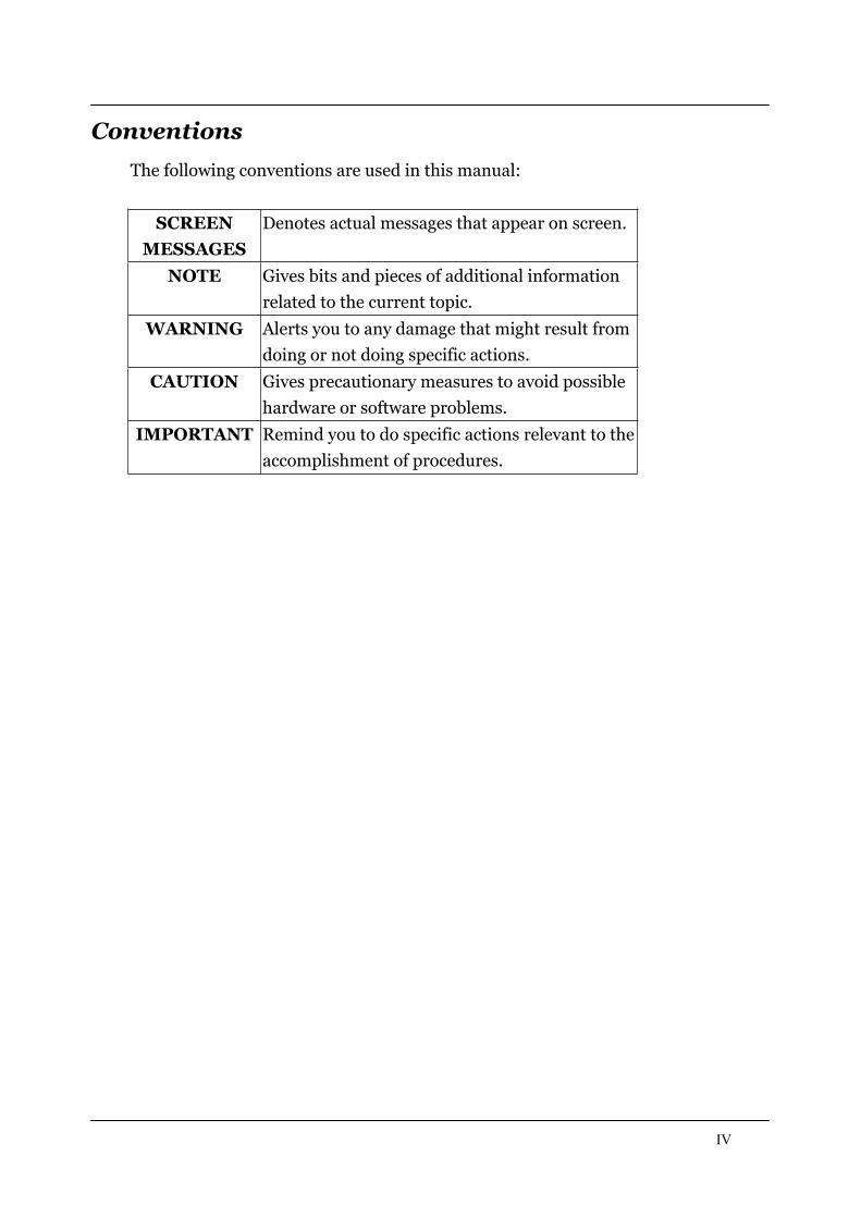
Conventions
The following conventions are used in this manual:
SCREEN
MESSAGES
Denotes actual messages that appear on screen.
NOTE Gives bits and pieces of additional information
related to the current topic.
WARNING Alerts you to any damage that might result from
doing or not doing specific actions.
CAUTION Gives precautionary measures to avoid possible
hardware or software problems.
IMPORTANT Remind you to do specific actions relevant to the
accomplishment of procedures.
V
Preface
Before using this information and the product it supports, please read the
following general information.
1. This Service Guide provides you with all technical information relating to
the BASIC CONFIGURATION decided for Acer's "global" product offering.
To better fit local market requirements and enhance product
competitiveness, your regional office MAY have decided to extend the
functionality of a machine (e.g. add-on card, modem, or extra memory
capability). These LOCALIZED FEATURES will NOT be covered in this
generic service guide. In such cases, please contact your regional offices or
the responsible personnel/channel to provide you with further technical
details.
2. Please note WHEN ORDERING FRU PARTS, that you should check the
most up-to-date information available on your regional web or channel. If,
for whatever reason, a part number change is made, it will not be noted in
the printed Service Guide. For ACER-AUTHORIZED SERVICE
PROVIDERS, your Acer office may have a DIFFERENT part number code
to those given in the FRU list of this printed Service Guide. You MUST use
the list provided by your regional Acer office to order FRU parts for repair
and service of customer machines.
1
Chapter 1 System Specifications 1
Features…………………………………………………………………………... 1 Main board Placement……………………………………………………….10Block Diagram…………………………………………………………………..11Aspire L5100 Front Panel……..……....…………………….............….12Aspire L5100 Rear Panel..............……………….………………….…..13Veriton L410 Front Panel………..........………….......…………….….14Veriton L410 Rear Panel………..........………........……….……………15Hardware Specifications and Configurations………......…….…….16Power Management Function (ACPI support function)………….21
Chapter 2 System Utilities 22
Entering Setup………………………………………………………………..23Product Information………………………………………………………..25Standard CMOS Features…………………………………………………26Advanced BIOS Features………………………………………………….29Integrated Peripherals……………………………………………………..33Power Management…………………………………………………………40PnP/PCI Configuration…………………………………………………….43PC Health Status……………………………………………………..…......45Frequency/Voltage Control……………..……………………………….46Load Default Settings………………………………………………..……. 48Set Supervisor/User Password……………………………….…………49Save & Exit Setup………………………………………………….…………51Exit Without Saving………………………………………………….……..52
Chapter 3 Machine Disassembly and Replacement 53
General Information………………………………………………………. 54Disassembly Procedure……………………………………………………55Aspire L5100 Disassembly Procedure………................…………56Veriton L410 Disassembly procedure……..........….........………64
Chapter 4 Troubleshooting 72
Chapter 5 Jumper and Connector Information 73
Jumper Setting……………………………………………………………….73
Chapter 6 FRU (Field Replaceable Unit) List 75
Exploded Diagram………………………………………………………….76Parts……………………………………………………………………………..79
1
System Specifications
Features
Operating System
Microsoft Windows Vista (Home Basic, Home Premium, Business)
Processor
Socket Type: AMD AM2 socket processors
Processor Type:
AMD Sempron 3400+/3500+/3600+/3800+ 35W TDP
AMD Athlon64 3500+3800+ 45W TDP
AMD Athlon64x2 4000+/4400+/4800+/5000+/5200+ 65W
TDP
Chipset
North Bridge: RS690 (A12)
South Bridge: SB600 (A21)
2
PCB
Form Factor: Micro ATX
Dimension/Layer: 234 x172mm
Memory
Memory Type: Dual Channel DDR2 667/533, SO-DIMM
Support single channel 64 bit mode with maximum memory size up
to 2GB
Support un-buffered DIMM s only
DIMM Slot: 2
Memory Max: 512MB / 2GB DDR2 memory technologies
Capacity: 256MB to 1 GB DDR2 533/667 DDR2 SO-DIMM support
Graphics
ATI RS690 on die graphic solution
DVMT 4.0 technology support
3
Integrated a DirectX9.0 compliant 2D/3D graphics core
Integrated a ATI Radeon X700-based graphics engine
PCI
PCI Express Slot Type: x16
Support 1x Mini PCIe x1
PCI supported
PCI supported
IDE interface
Single PATA channel support
Supports PIO, Multi-word DMA, and Ultra DMA 33/66/100/133
modes
Support 1 IDE port
SATA
Support 2 SATA port, complying with the SATA 2.0 specification
4
Support SATA II 3.0GHz PHY, with backward compatibility with
1.5GHz
Audio
Audio Type: HD audio codec
Audio Channel: 7.1 channel
Realtek ALC888-GR,colay with ALC888S(default)
Support S/PDIF: S/PDIF-out header (1*4)
LAN
LAN-RTL 8111C 10/100/1000 Gigabit Controller
10/100/1000BASE-T IEEE 802.3, IEEE802.3u, IEEE802.3ab
compliant
Support Fully Duplex flow control (IEE 802.3x)
Supports pair swap/polarity/skew correction.
Wake-on-LAN and remote wake-up support.
5
USB
X9 USB2.0/1.1(Rear 4 ports, Front 5ports/1 for KB wireless
receiver, 4 for 40pin B2B header)
1394
1394 header x 1 and Back I/O *1 (TSB43AB23PDTG4 2-port)
BIOS
BIOS Type: SST 49LF004B FWH
4Mbit symmetrical Flash
Note:
Boot ROM should be included (PXE function should be built in
with default and RPL function is optional by service BIOS)
Compliant with latest ASF 2.0 spec
Compliant with latest SMT 2.0 spec
Compliant with latest Intel Virtualization Technology spec
6
I/O Connector
Controller: Super I/O ITE 8718F-EX with hardware monitor
Rear I/O Connector
Dual stack USB ports with 1394 connector for 1394 SKU.
Dual Stack USB ports for non-1394 SKU.
Dual Stack USB ports with RJ-45 connector
Vertical Audio connector with 5 JACKS+SPDIF OUT.
DVI-I port
HDMI port
DC IN JACK
On-board connectors
LGA AM2 CPU socket
DDR2 memory sockets
PCI Express x 1 slot
7
PCI slots
SATA2 connectors
Serial port 2*5 pin connector (2nd serial port)
HD audio digital header
4 pin CPU Fan connector
3 pin System FAN connector with linear circuit
1394 header
Jumper for clear CMOS
Color management for on board connecters (please refer to Acer
spec)
Header for CIR & IR blaster function (Check ITE Solution)
Power Supply
Fully supports ACPI states S1,S3,S4,and S5
The Chip Power Management Support state can be achieved by

8
software control bits
Hardware controlled intelligent clock gate
Support for Cool`n`Quiet via FID/VID change
Support for PowerNow
Support ATI PowerOnDemand
Power On Suspend (POS) or ACPI S1 support
Suspend to RAM (STR) or ACPI S3 support
Suspend to Disk (STD) or ACPI S4/S5 support
Supports C2, C3, and C4 states
Provides clock generator and CPU STPCLK# control
Supports dynamic lane reduction for the PCI-E interface
System Clocks
Memory DDR2: 667/533
PCI 33 MHz
9
PCI Express 100 MHz
USB 48 MHz
SIO 48 MHz
RTC 32.768 KHz
LAN 25MHz
Audio Codec 24MHz
10
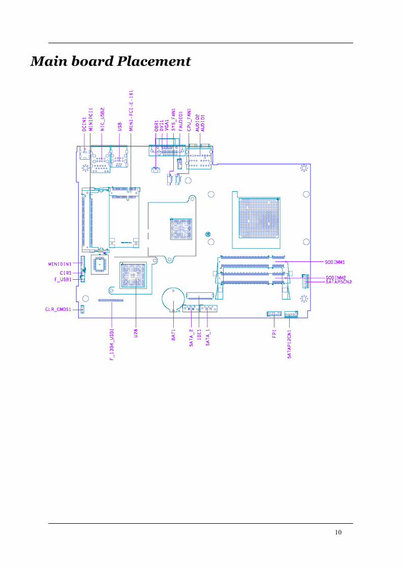
Main board Placement
11
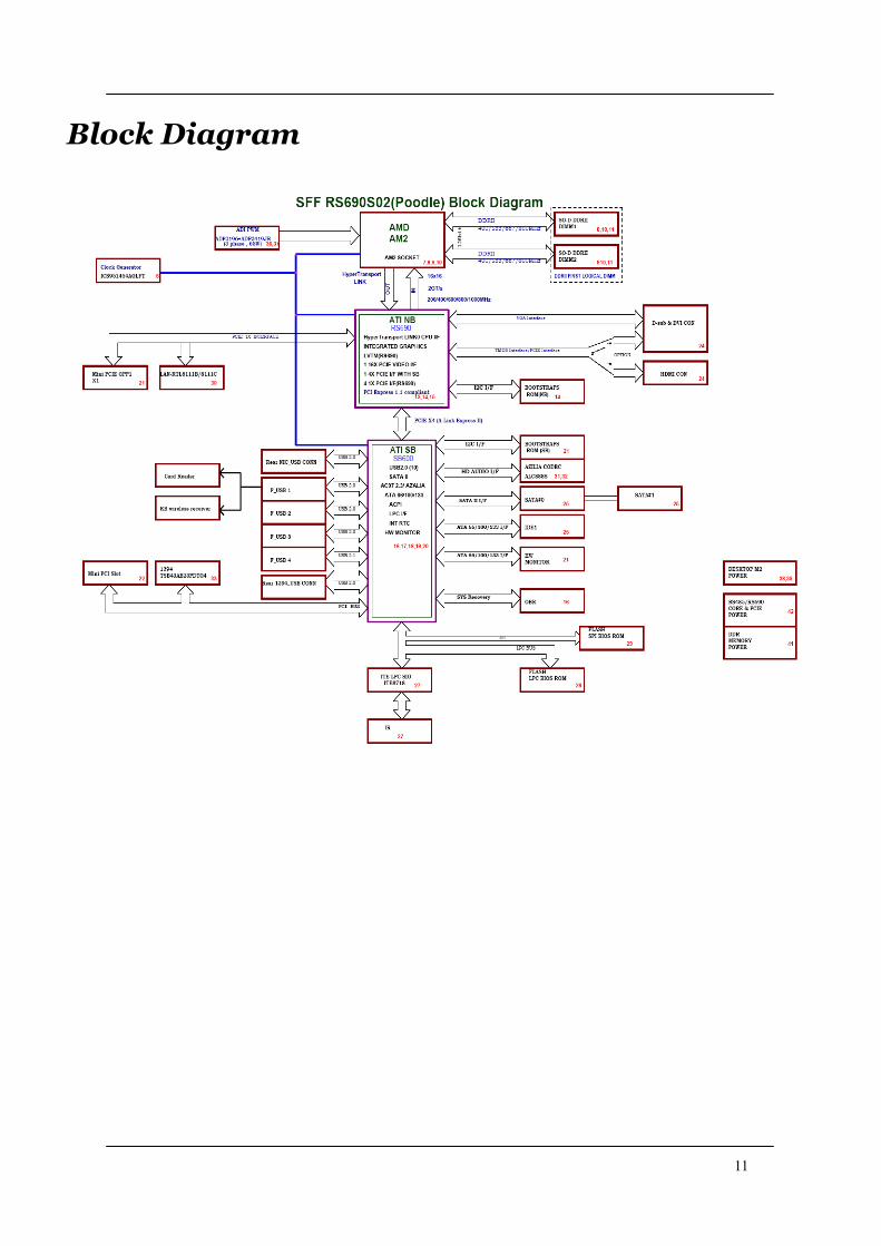
Block Diagram
12
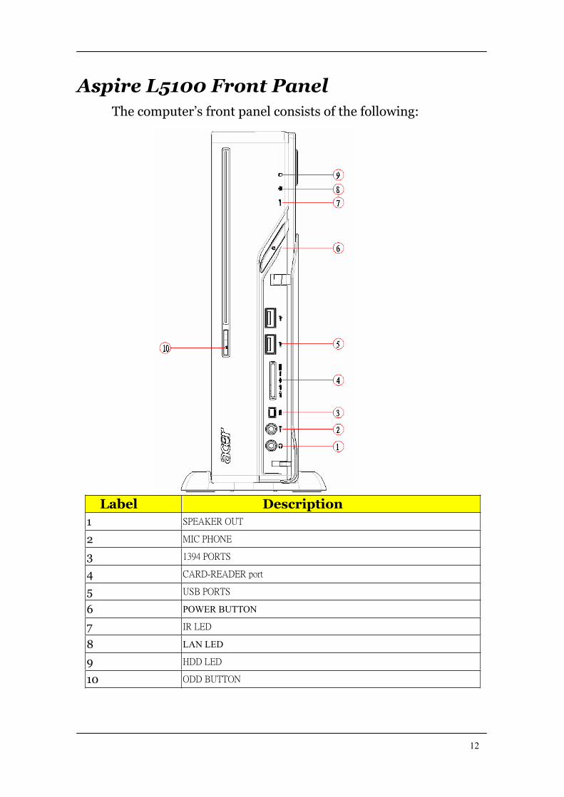
Aspire L5100 Front Panel
The computer’s front panel consists of the following:
Label Description
1
2
3
4
5
6 POWER BUTTON
7
8 LAN LED
9
10
13
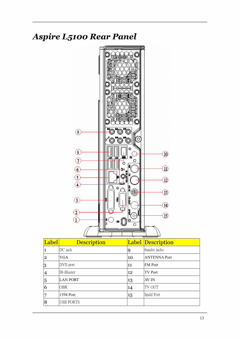
Aspire L5100 Rear Panel
Label Description Label Description
1 9
2 VGA 10 ANTENNA Port
3 11 FM Port
4 12 TV Port
5 LAN PORT 13 AV IN
6 14
7 1394 Port 15
8
14
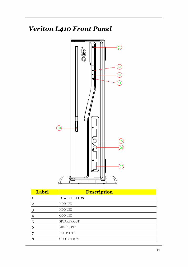
Veriton L410 Front Panel
Label Description
1 POWER BUTTON
2
3
4
5
6
7
8
15
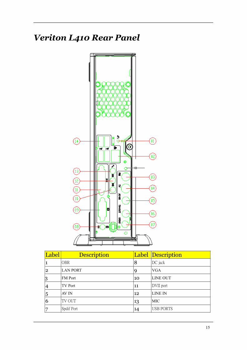
Veriton L410 Rear Panel
Label Description Label Description
1 8
2 LAN PORT 9 VGA
3 FM Port 10 LINE OUT
4 TV Port 11
5 AV IN 12 LINE IN
6 13 MIC
7 14
16
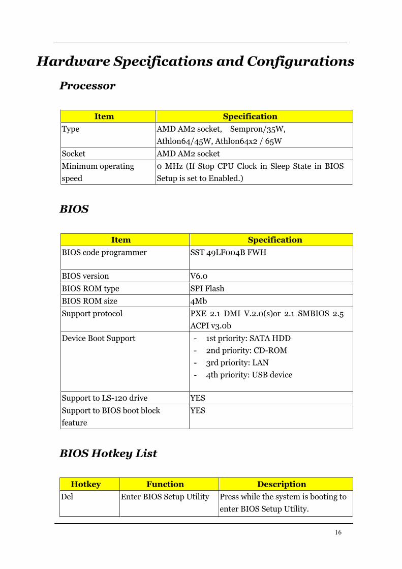
Hardware Specifications and Configurations
Processor
Item Specification
Type AMD AM2 socket, Sempron/35W,
Athlon64/45W, Athlon64x2 / 65W
Socket AMD AM2 socket
Minimum operating
speed
0 MHz (If Stop CPU Clock in Sleep State in BIOS
Setup is set to Enabled.)
BIOS
Item Specification
BIOS code programmer SST 49LF004B FWH
BIOS version V6.0
BIOS ROM type SPI Flash
BIOS ROM size 4Mb
Support protocol PXE 2.1 DMI V.2.0(s)or 2.1 SMBIOS 2.5
ACPI v3.0b
Device Boot Support - 1st priority: SATA HDD
- 2nd priority: CD-ROM
- 3rd priority: LAN
- 4th priority: USB device
Support to LS-120 drive YES
Support to BIOS boot block
feature
YES
BIOS Hotkey List
Hotkey Function Description
Del Enter BIOS Setup Utility Press while the system is booting to
enter BIOS Setup Utility.

17
Main Board Major Chips
Item Specification
North Bridge RS690 (A12)
South Bridge SB600 (A21)
APG controller RS690 (A12)
Super I/O controller ITE8718
Audio controller Realtek ALC888-GR,colay with ALC888S(default)
LAN controller LAN-RTL 8111C
HDD controller ITE8718
Keyboard controller ITE8718
Memory Combinations
Slot Memory Total Memory
Slot 1 256MB, 512MB, 1GB 256MB~1GB
Slot 2 256MB, 512MB, 1GB 256MB~1GB
Maximum System Memory Supported 256MB~2GB
System Memory
Item Specification
Memory slot number 2 slot
Support Memory size per socket 256MB, 512MB, 1GB
Support memory type DDR2
Support memory interface DDR2 667/533
Support memory voltage 1.8V
Support to parity check feature Yes
Support to error correction code
(ECC) feature
No
Memory module combinations You can install memory modules in any
combination as long as they match the
above specifications.
18
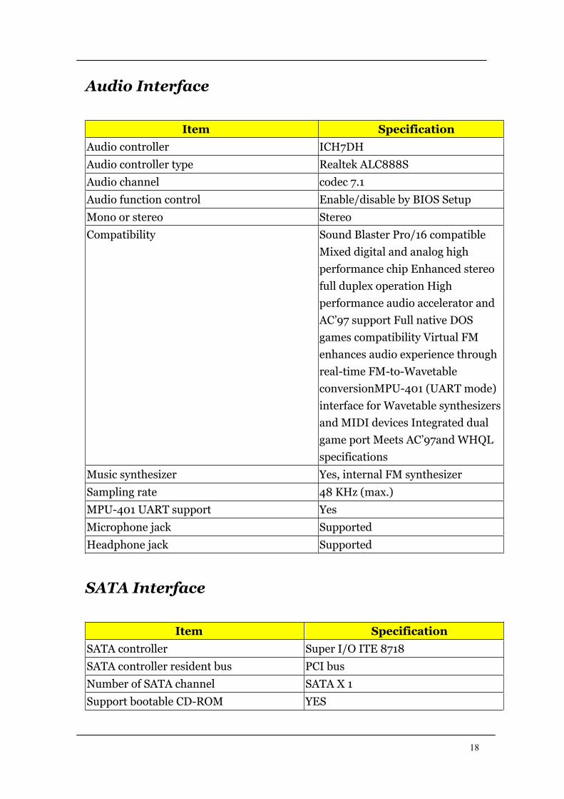
Audio Interface
Item Specification
Audio controller ICH7DH
Audio controller type Realtek ALC888S
Audio channel codec 7.1
Audio function control Enable/disable by BIOS Setup
Mono or stereo Stereo
Compatibility Sound Blaster Pro/16 compatible
Mixed digital and analog high
performance chip Enhanced stereo
full duplex operation High
performance audio accelerator and
AC’97 support Full native DOS
games compatibility Virtual FM
enhances audio experience through
real-time FM-to-Wavetable
conversionMPU-401 (UART mode)
interface for Wavetable synthesizers
and MIDI devices Integrated dual
game port Meets AC’97and WHQL
specifications
Music synthesizer Yes, internal FM synthesizer
Sampling rate 48 KHz (max.)
MPU-401 UART support Yes
Microphone jack Supported
Headphone jack Supported
SATA Interface
Item Specification
SATA controller Super I/O ITE 8718
SATA controller resident bus PCI bus
Number of SATA channel SATA X 1
Support bootable CD-ROM YES
19
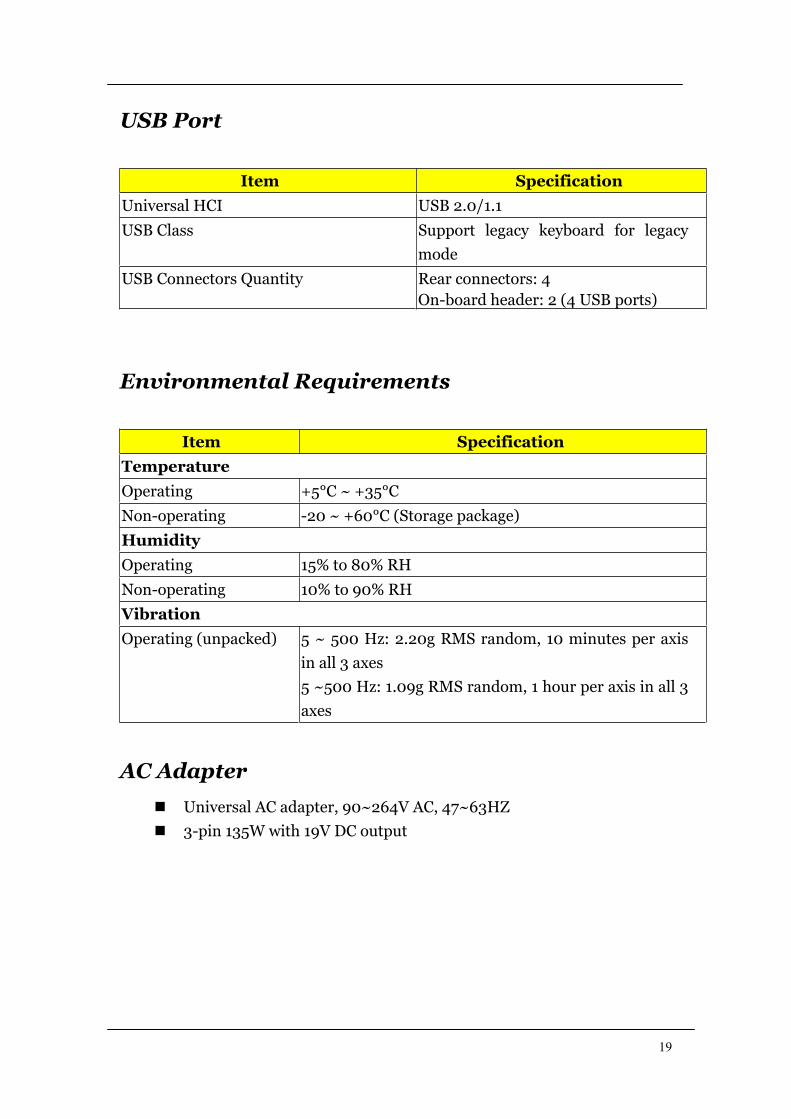
USB Port
Item Specification
Universal HCI USB 2.0/1.1
USB Class Support legacy keyboard for legacy
mode
USB Connectors Quantity Rear connectors: 4
On-board header: 2 (4 USB ports)
Environmental Requirements
Item Specification
Temperature
Operating +5°C ~ +35°C
Non-operating -20 ~ +60°C (Storage package)
Humidity
Operating 15% to 80% RH
Non-operating 10% to 90% RH
Vibration
Operating (unpacked) 5 ~ 500 Hz: 2.20g RMS random, 10 minutes per axis
in all 3 axes
5 ~500 Hz: 1.09g RMS random, 1 hour per axis in all 3
axes
AC Adapter
Universal AC adapter, 90~264V AC, 47~63HZ
3-pin 135W with 19V DC output
20
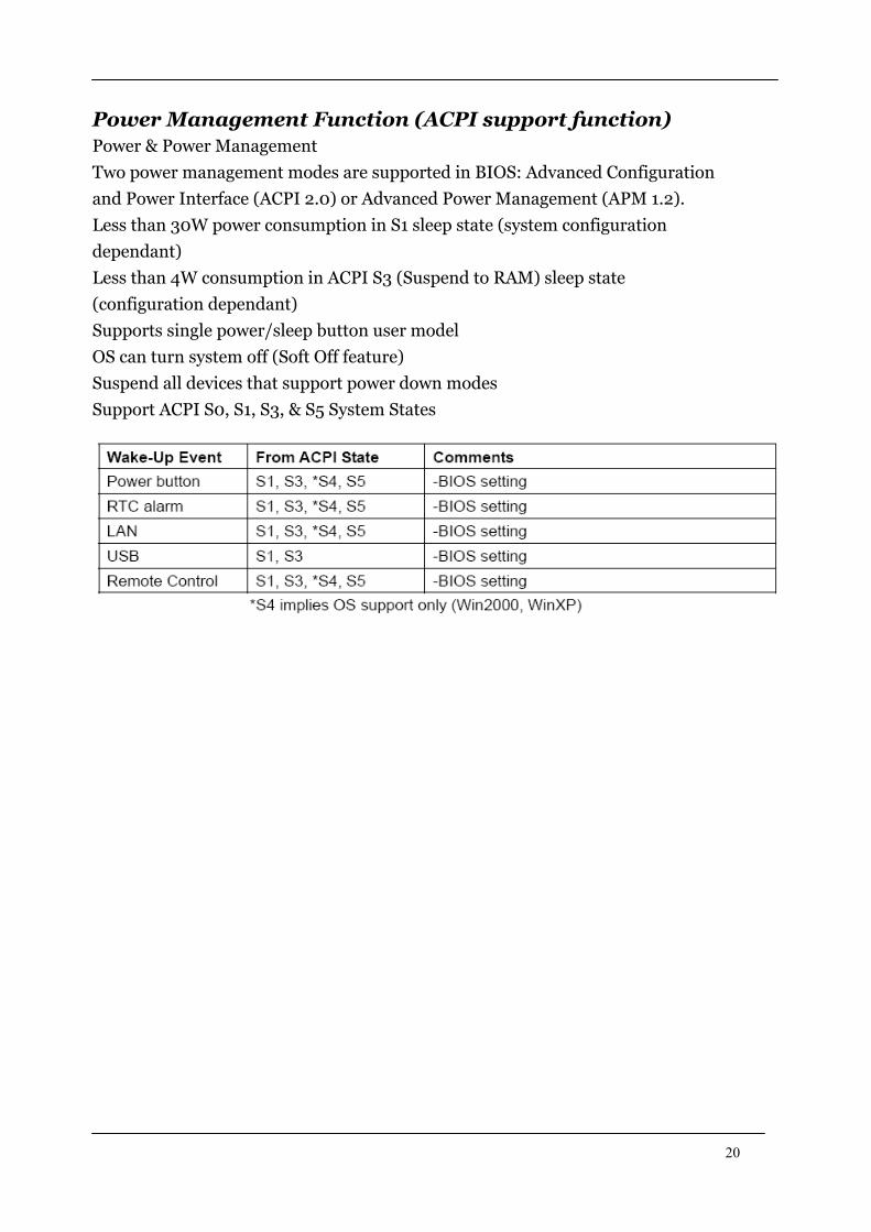
Power Management Function (ACPI support function)
Power & Power Management
Two power management modes are supported in BIOS: Advanced Configuration
and Power Interface (ACPI 2.0) or Advanced Power Management (APM 1.2).
Less than 30W power consumption in S1 sleep state (system configuration
dependant)
Less than 4W consumption in ACPI S3 (Suspend to RAM) sleep state
(configuration dependant)
Supports single power/sleep button user model
OS can turn system off (Soft Off feature)
Suspend all devices that support power down modes
Support ACPI S0, S1, S3, & S5 System States
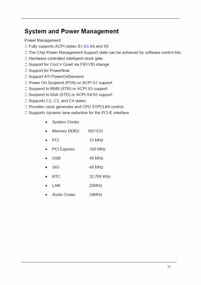
21

22
System Utilities The manufacturer or the dealer already configures most systems.
There is no need to run Setup when starting the computer unless
you get a Run Setup message.
The Setup program loads configuration values into the battery-backed
nonvolatile memory called CMOS RAM.
This memory area is not part of the system RAM.
NOTE: If you repeatedly receive Run Setup messages, the battery may be
bad/flat. In this case, the system cannot retain configuration values in CMOS.
Before you run Setup, make sure that you have saved all open files. The
system reboots immediately after you exit Setup.
23
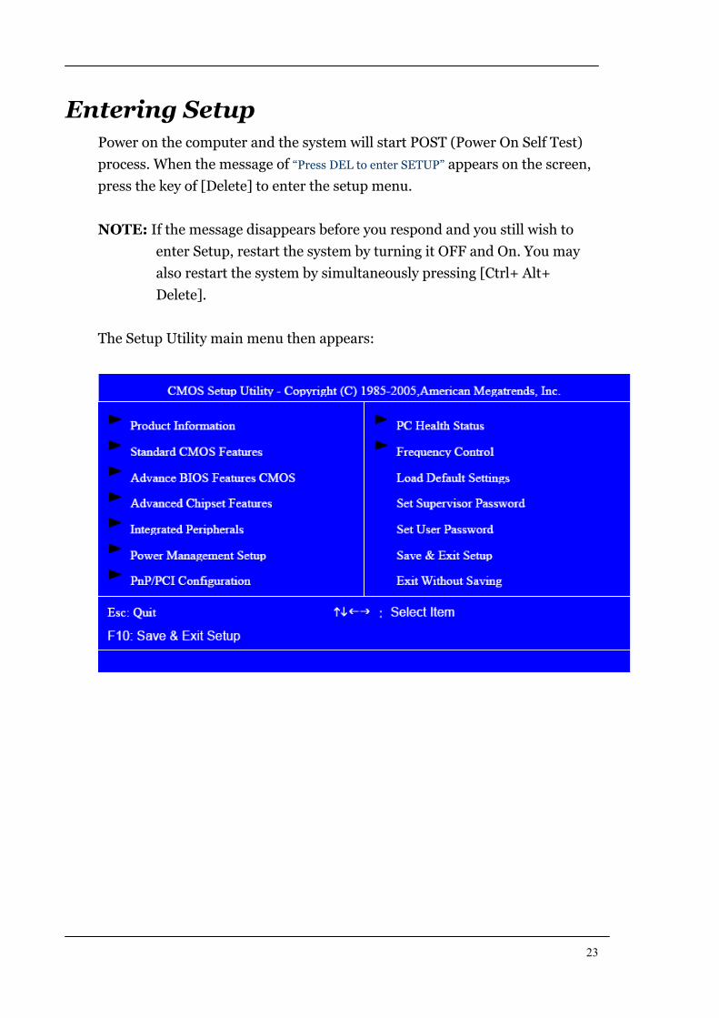
Entering Setup Power on the computer and the system will start POST (Power On Self Test)
process. When the message of “Press DEL to enter SETUP” appears on the screen,
press the key of [Delete] to enter the setup menu.
NOTE: If the message disappears before you respond and you still wish to
enter Setup, restart the system by turning it OFF and On. You may
also restart the system by simultaneously pressing [Ctrl+ Alt+
Delete].
The Setup Utility main menu then appears:
24
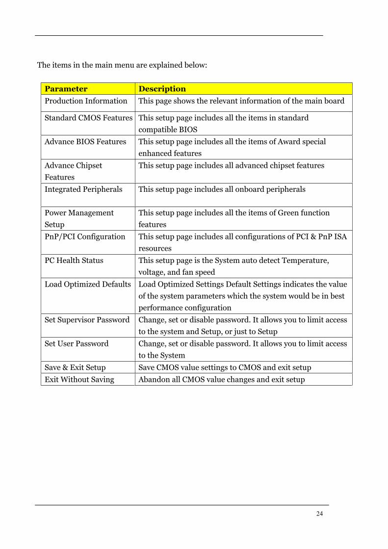
The items in the main menu are explained below:
Parameter Description
Production Information This page shows the relevant information of the main board
Standard CMOS Features This setup page includes all the items in standard
compatible BIOS
Advance BIOS Features This setup page includes all the items of Award special
enhanced features
Advance Chipset
Features
This setup page includes all advanced chipset features
Integrated Peripherals This setup page includes all onboard peripherals
Power Management
Setup
This setup page includes all the items of Green function
features
PnP/PCI Configuration This setup page includes all configurations of PCI & PnP ISA
resources
PC Health Status This setup page is the System auto detect Temperature,
voltage, and fan speed
Load Optimized Defaults Load Optimized Settings Default Settings indicates the value
of the system parameters which the system would be in best
performance configuration
Set Supervisor Password Change, set or disable password. It allows you to limit access
to the system and Setup, or just to Setup
Set User Password Change, set or disable password. It allows you to limit access
to the System
Save & Exit Setup Save CMOS value settings to CMOS and exit setup
Exit Without Saving Abandon all CMOS value changes and exit setup
25
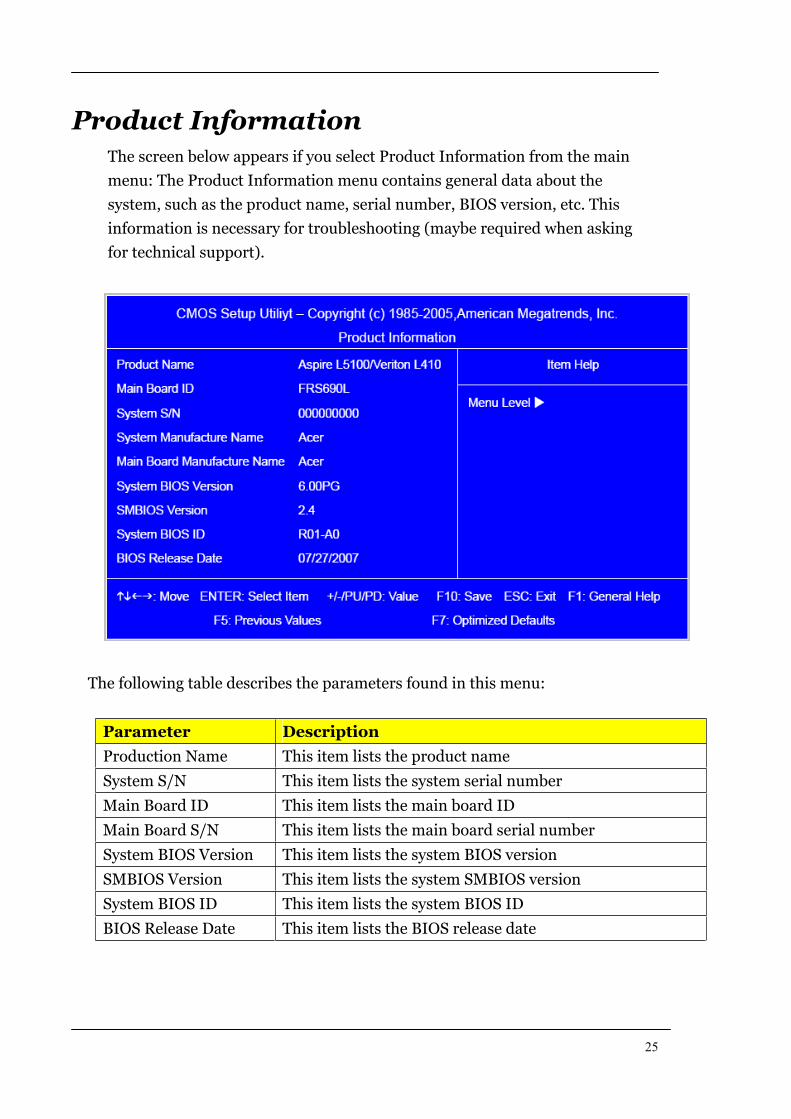
Product Information The screen below appears if you select Product Information from the main
menu: The Product Information menu contains general data about the
system, such as the product name, serial number, BIOS version, etc. This
information is necessary for troubleshooting (maybe required when asking
for technical support).
The following table describes the parameters found in this menu:
Parameter Description
Production Name This item lists the product name
System S/N This item lists the system serial number
Main Board ID This item lists the main board ID
Main Board S/N This item lists the main board serial number
System BIOS Version This item lists the system BIOS version
SMBIOS Version This item lists the system SMBIOS version
System BIOS ID This item lists the system BIOS ID
BIOS Release Date This item lists the BIOS release date
26
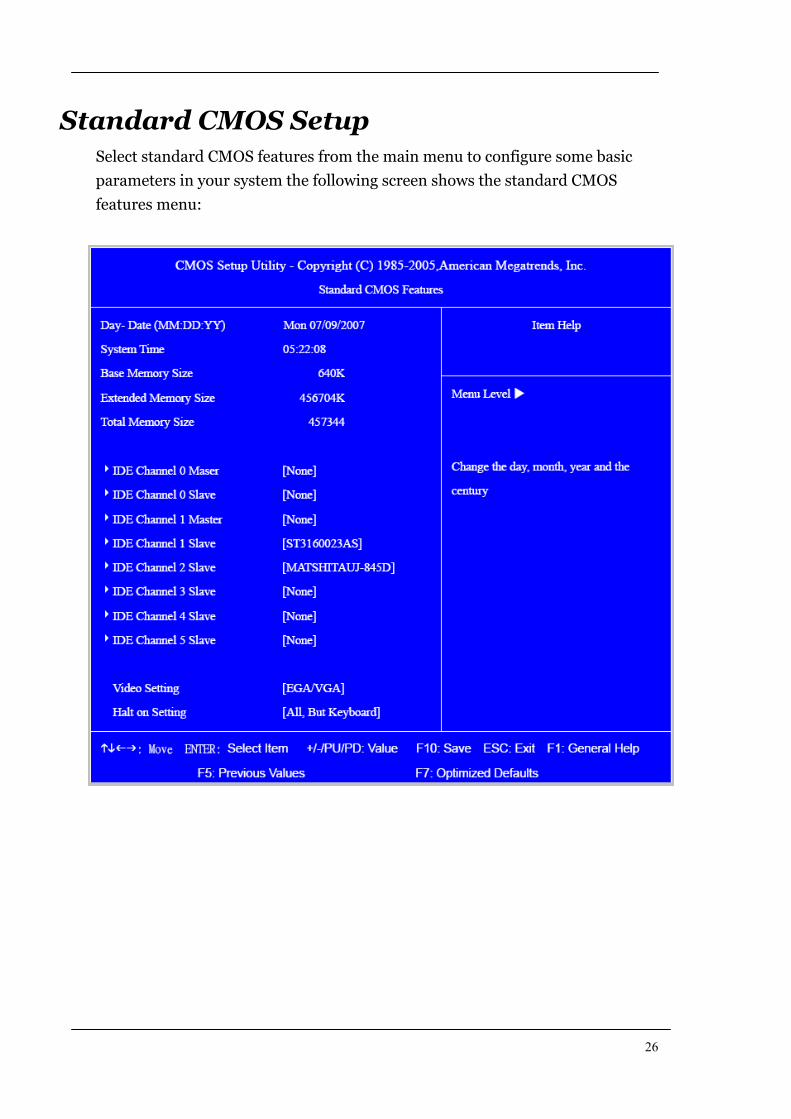
Standard CMOS Setup Select standard CMOS features from the main menu to configure some basic
parameters in your system the following screen shows the standard CMOS
features menu:
27
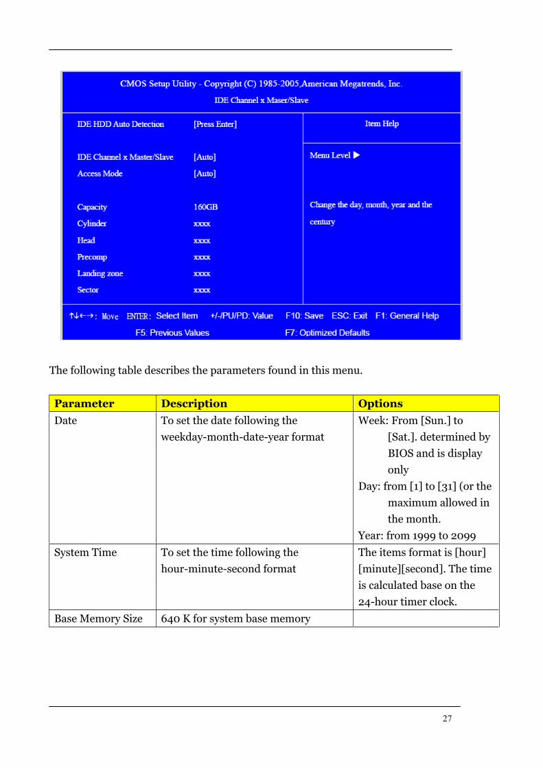
The following table describes the parameters found in this menu.
Parameter Description Options
Date To set the date following the
weekday-month-date-year format
Week: From [Sun.] to
[Sat.]. determined by
BIOS and is display
only
Day: from [1] to [31] (or the
maximum allowed in
the month.
Year: from 1999 to 2099
System Time To set the time following the
hour-minute-second format
The items format is [hour]
[minute][second]. The time
is calculated base on the
24-hour timer clock.
Base Memory Size 640 K for system base memory
28
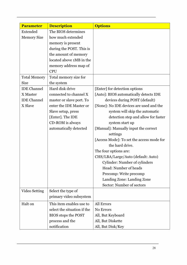
Parameter Description Options
Extended
Memory Size
The BIOS determines
how much extended
memory is present
during the POST. This is
the amount of memory
located above 1MB in the
memory address map of
CPU
Total Memory
Size
Total memory size for
the system
IDE Channel
X Master
IDE Channel
X Slave
Hard disk drive
connected to channel X
master or slave port. To
enter the IDE Master or
Slave setup, press
[Enter]. The IDE
CD-ROM is always
automatically detected
[Enter] for detection options
[Auto]: BIOS automatically detects IDE
devices during POST (default)
[None]: No IDE devices are used and the
system will skip the automatic
detection step and allow for faster
system start up
[Manual]: Manually input the correct
settings
[Access Mode]: To set the access mode for
the hard drive.
The four options are:
CHS/LBA/Large/Auto (default: Auto)
Cylinder: Number of cylinders
Head: Number of heads
Precomp: Write precomp
Landing Zone: Landing Zone
Sector: Number of sectors
Video Setting Select the type of
primary video subsystem
Halt on This item enables use to
select the situation if the
BIOS stops the POST
process and the
notification
All Errors
No Errors
All, But Keyboard
All, But Diskette
All, But Disk/Key
29
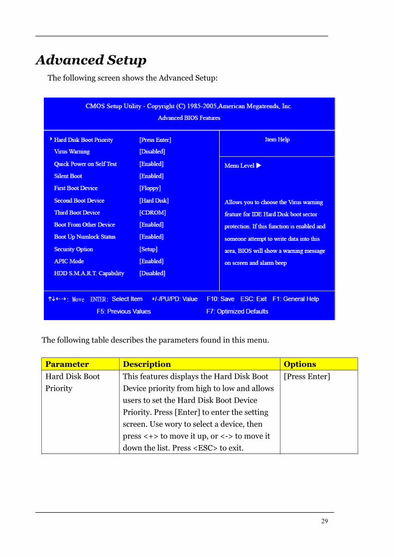
Advanced Setup The following screen shows the Advanced Setup:
The following table describes the parameters found in this menu.
Parameter Description Options
Hard Disk Boot
Priority
This features displays the Hard Disk Boot
Device priority from high to low and allows
users to set the Hard Disk Boot Device
Priority. Press [Enter] to enter the setting
screen. Use wory to select a device, then
press <+> to move it up, or <-> to move it
down the list. Press <ESC> to exit.
[Press Enter]
30
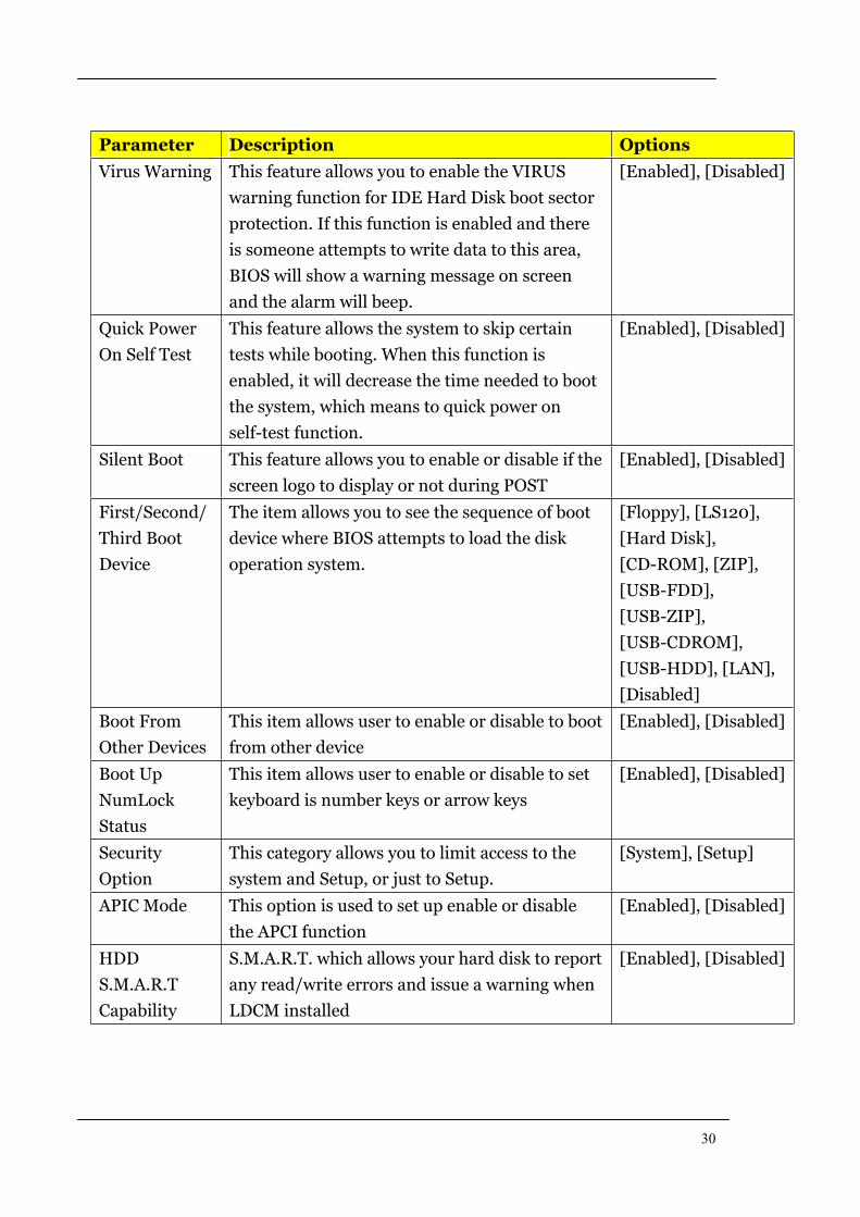
Parameter Description Options
Virus Warning This feature allows you to enable the VIRUS
warning function for IDE Hard Disk boot sector
protection. If this function is enabled and there
is someone attempts to write data to this area,
BIOS will show a warning message on screen
and the alarm will beep.
[Enabled], [Disabled]
Quick Power
On Self Test
This feature allows the system to skip certain
tests while booting. When this function is
enabled, it will decrease the time needed to boot
the system, which means to quick power on
self-test function.
[Enabled], [Disabled]
Silent Boot This feature allows you to enable or disable if the
screen logo to display or not during POST
[Enabled], [Disabled]
First/Second/
Third Boot
Device
The item allows you to see the sequence of boot
device where BIOS attempts to load the disk
operation system.
[Floppy], [LS120],
[Hard Disk],
[CD-ROM], [ZIP],
[USB-FDD],
[USB-ZIP],
[USB-CDROM],
[USB-HDD], [LAN],
[Disabled]
Boot From
Other Devices
This item allows user to enable or disable to boot
from other device
[Enabled], [Disabled]
Boot Up
NumLock
Status
This item allows user to enable or disable to set
keyboard is number keys or arrow keys
[Enabled], [Disabled]
Security
Option
This category allows you to limit access to the
system and Setup, or just to Setup.
[System], [Setup]
APIC Mode This option is used to set up enable or disable
the APCI function
[Enabled], [Disabled]
HDD
S.M.A.R.T
Capability
S.M.A.R.T. which allows your hard disk to report
any read/write errors and issue a warning when
LDCM installed
[Enabled], [Disabled]
31
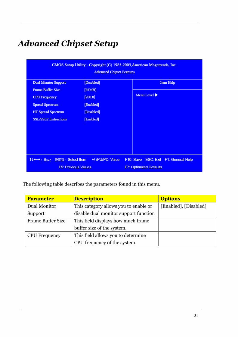
Advanced Chipset Setup
The following table describes the parameters found in this menu.
Parameter Description Options
Dual Monitor
Support
This category allows you to enable or
disable dual monitor support function
[Enabled], [Disabled]
Frame Buffer Size This field displays how much frame
buffer size of the system.
CPU Frequency This field allows you to determine
CPU frequency of the system.
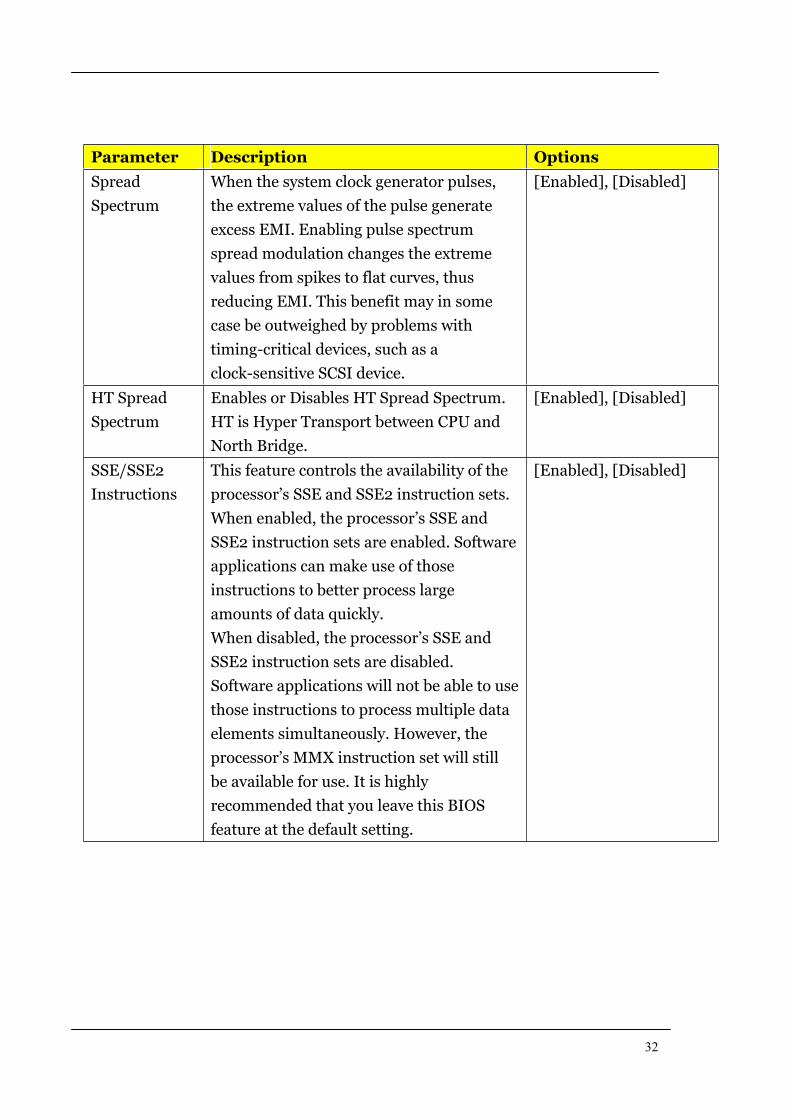
32
Parameter Description Options
Spread
Spectrum
When the system clock generator pulses,
the extreme values of the pulse generate
excess EMI. Enabling pulse spectrum
spread modulation changes the extreme
values from spikes to flat curves, thus
reducing EMI. This benefit may in some
case be outweighed by problems with
timing-critical devices, such as a
clock-sensitive SCSI device.
[Enabled], [Disabled]
HT Spread
Spectrum
Enables or Disables HT Spread Spectrum.
HT is Hyper Transport between CPU and
North Bridge.
[Enabled], [Disabled]
SSE/SSE2
Instructions
This feature controls the availability of the
processor’s SSE and SSE2 instruction sets.
When enabled, the processor’s SSE and
SSE2 instruction sets are enabled. Software
applications can make use of those
instructions to better process large
amounts of data quickly.
When disabled, the processor’s SSE and
SSE2 instruction sets are disabled.
Software applications will not be able to use
those instructions to process multiple data
elements simultaneously. However, the
processor’s MMX instruction set will still
be available for use. It is highly
recommended that you leave this BIOS
feature at the default setting.
[Enabled], [Disabled]
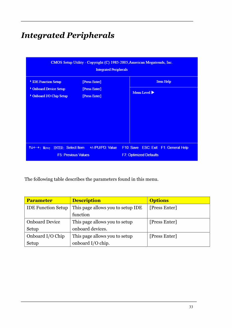
33
Integrated Peripherals
The following table describes the parameters found in this menu.
Parameter Description Options
IDE Function Setup This page allows you to setup IDE
function
[Press Enter]
Onboard Device
Setup
This page allows you to setup
onboard devices.
[Press Enter]
Onboard I/O Chip
Setup
This page allows you to setup
onboard I/O chip.
[Press Enter]
34
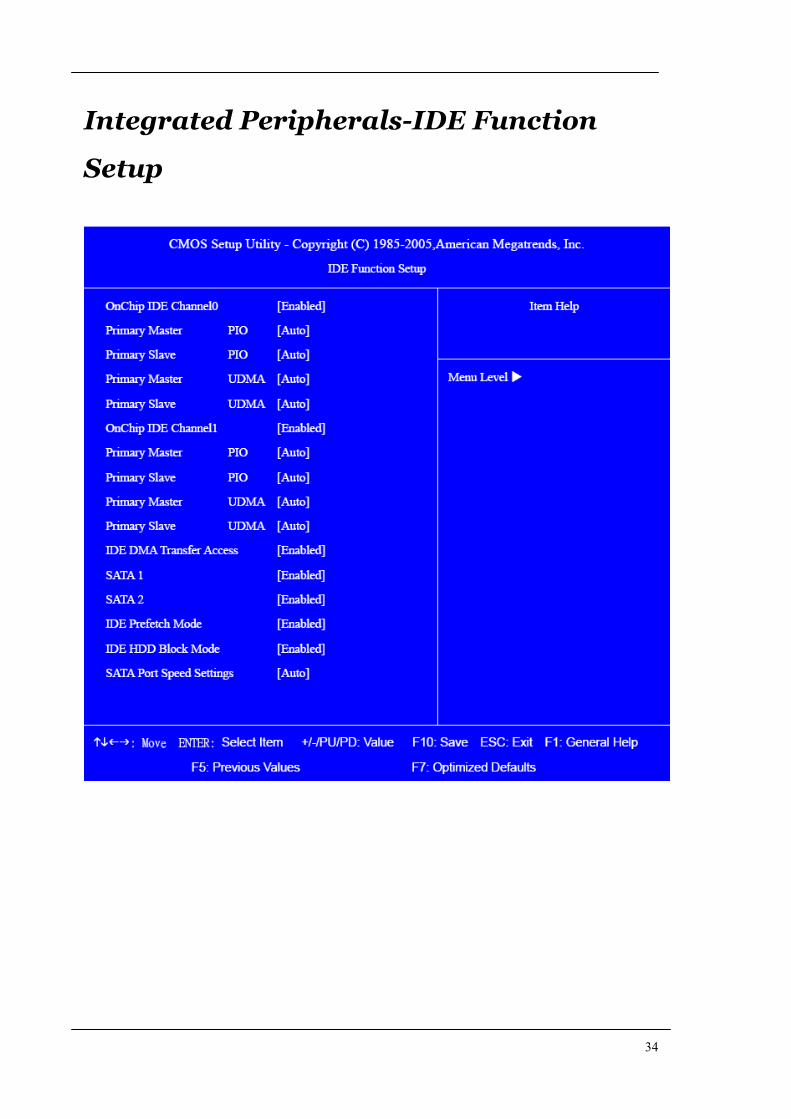
Integrated Peripherals-IDE Function
Setup
35
The following table describes the parameters found in this menu.
Parameter Description Options
IDE
Primary/Second
ary
Master/Slave
PIO
The four IDE PIO fields let you set a PIO mode (0-4)
for each of the four IDE devices that the onboard IDE
interface supports. Modes 0 through 4 provide
increased performance. In Auto mode, the system
automatically determines the best mode for each
device.
On-Chip IDE
First/Second
Channel
The Chipset contains a PCI IDE interface with support
for two IDE channels. Select Enabled to activate the
first and/or second IDE interface. Select Disabled to
deactivate an interface, if you install a primary and/or
secondary add-in IDE interface.
[Enabled],
[Disabled]
IDE
Primary/Second
ary
Master/Slave
UDMA
UDMA (Ultra DMA) is a DMA data transfer protocol
that utilized ATA transfer protocol that utilizes ATA
commands and the ATA bus to allow DMA commands
to transfer data ata maximum burst rate of 33 MB/s.
When you select Auto in the four IDE UDMA fields (for
each of up to four IDE devices that the internal PCI IDE
interface supports), the system automatically
determines the optimal data transfer rate for each IDE
device.
IDE DMA
Transfer Access
This category allows you to enable or disable DMA
transfer access of IDE device (or IDE HDD)
[Enabled],
[Disabled]
SATA 1/2 Enable/Disable Serial-ATA 1 or Serial-ATA-2. SATA 1
control port 1 and 3, SATA 2 control port 2 and 4.
IDE Prefetch
Mode
The onboard IDE drive interfaces supports IDE
prefetching, for faster drive accesses. If you install a
primary and/or secondary add-in IDE interface, set this
field to Disabled if the interface does not support
prefetching.
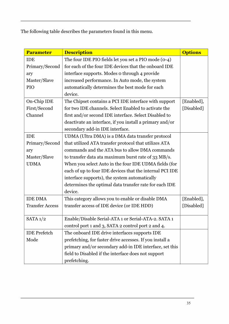
36
Parameter Description Options
IDE HDD Block
Mode
Block mode is also called block transfer, multiple
commands, or multiple sectors read/write. If your IDE
hard drive supports block mode(most new drives do),
select Enabled for automatic detection of the optimal
number of block read/write per sector the drive can
support.
[Enabled],
[Disabled]
SATA PORT
Speed Settings
This category allows you to determine the speed of
SATA port.
[Auto],
Integrated Peripherals-Onboard Device
Setup
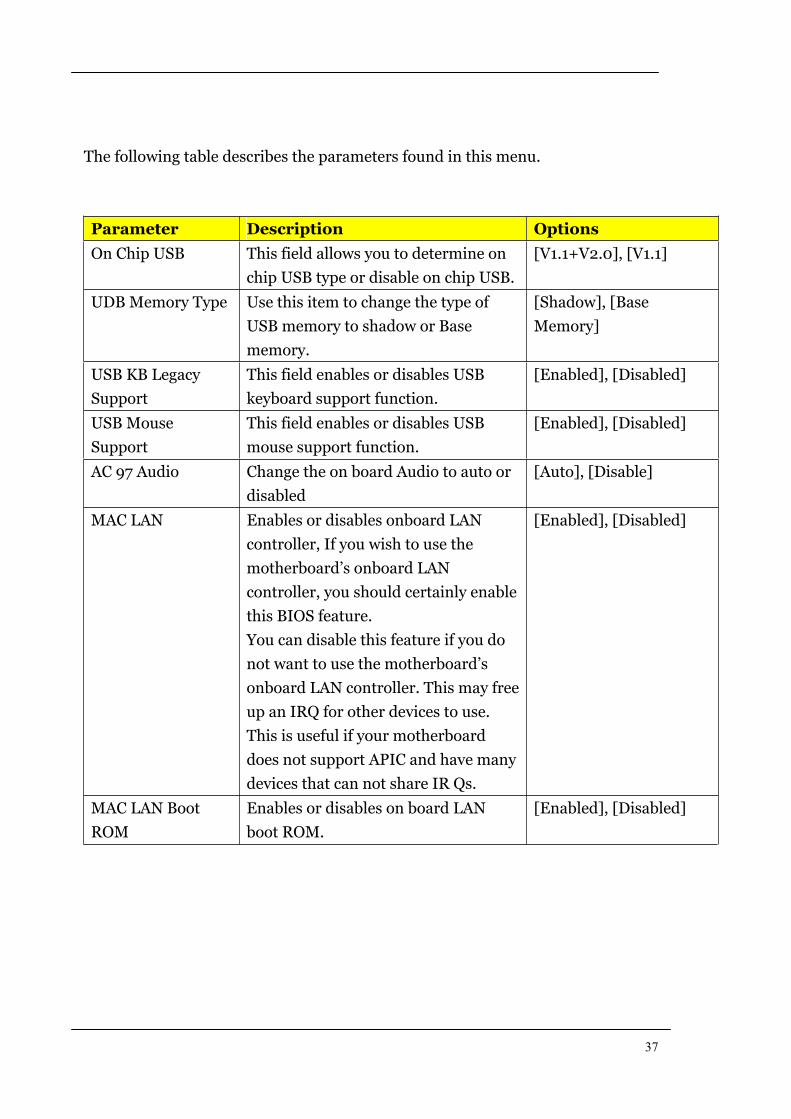
37
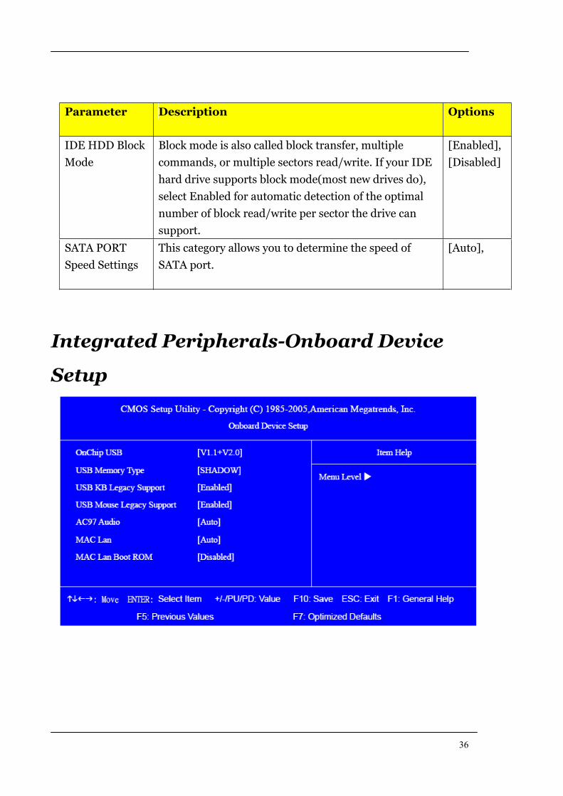
The following table describes the parameters found in this menu.
Parameter Description Options
On Chip USB This field allows you to determine on
chip USB type or disable on chip USB.
[V1.1+V2.0], [V1.1]
UDB Memory Type Use this item to change the type of
USB memory to shadow or Base
memory.
[Shadow], [Base
Memory]
USB KB Legacy
Support
This field enables or disables USB
keyboard support function.
[Enabled], [Disabled]
USB Mouse
Support
This field enables or disables USB
mouse support function.
[Enabled], [Disabled]
AC 97 Audio Change the on board Audio to auto or
disabled
[Auto], [Disable]
MAC LAN Enables or disables onboard LAN
controller, If you wish to use the
motherboard’s onboard LAN
controller, you should certainly enable
this BIOS feature.
You can disable this feature if you do
not want to use the motherboard’s
onboard LAN controller. This may free
up an IRQ for other devices to use.
This is useful if your motherboard
does not support APIC and have many
devices that can not share IR Qs.
[Enabled], [Disabled]
MAC LAN Boot
ROM
Enables or disables on board LAN
boot ROM.
[Enabled], [Disabled]
38
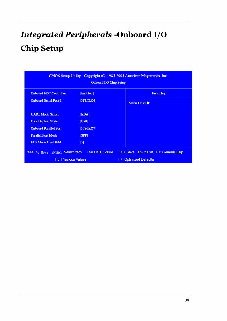
Integrated Peripherals -Onboard I/O
Chip Setup
39
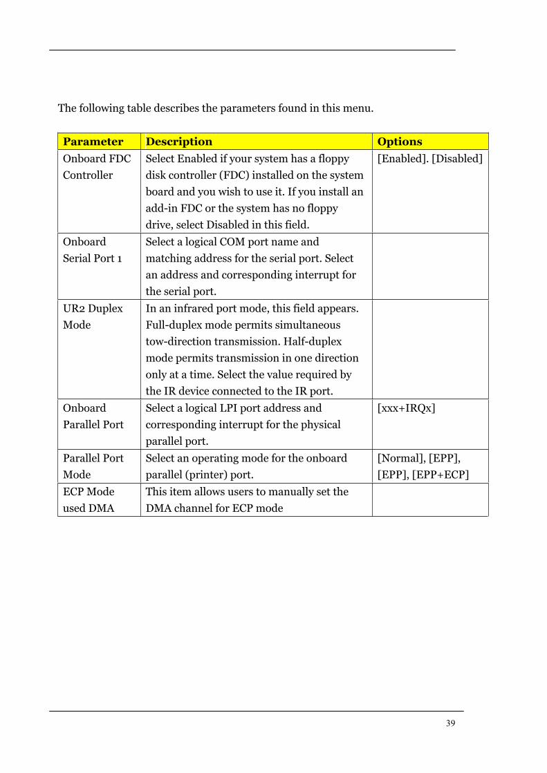
The following table describes the parameters found in this menu.
Parameter Description Options
Onboard FDC
Controller
Select Enabled if your system has a floppy
disk controller (FDC) installed on the system
board and you wish to use it. If you install an
add-in FDC or the system has no floppy
drive, select Disabled in this field.
[Enabled]. [Disabled]
Onboard
Serial Port 1
Select a logical COM port name and
matching address for the serial port. Select
an address and corresponding interrupt for
the serial port.
UR2 Duplex
Mode
In an infrared port mode, this field appears.
Full-duplex mode permits simultaneous
tow-direction transmission. Half-duplex
mode permits transmission in one direction
only at a time. Select the value required by
the IR device connected to the IR port.
Onboard
Parallel Port
Select a logical LPI port address and
corresponding interrupt for the physical
parallel port.
[xxx+IRQx]
Parallel Port
Mode
Select an operating mode for the onboard
parallel (printer) port.
[Normal], [EPP],
[EPP], [EPP+ECP]
ECP Mode
used DMA
This item allows users to manually set the
DMA channel for ECP mode
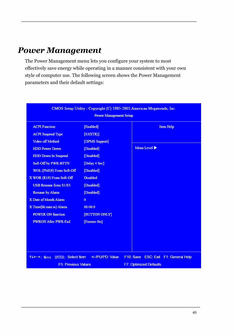
40
Power Management The Power Management menu lets you configure your system to most
effectively save energy while operating in a manner consistent with your own
style of computer use. The following screen shows the Power Management
parameters and their default settings:
41
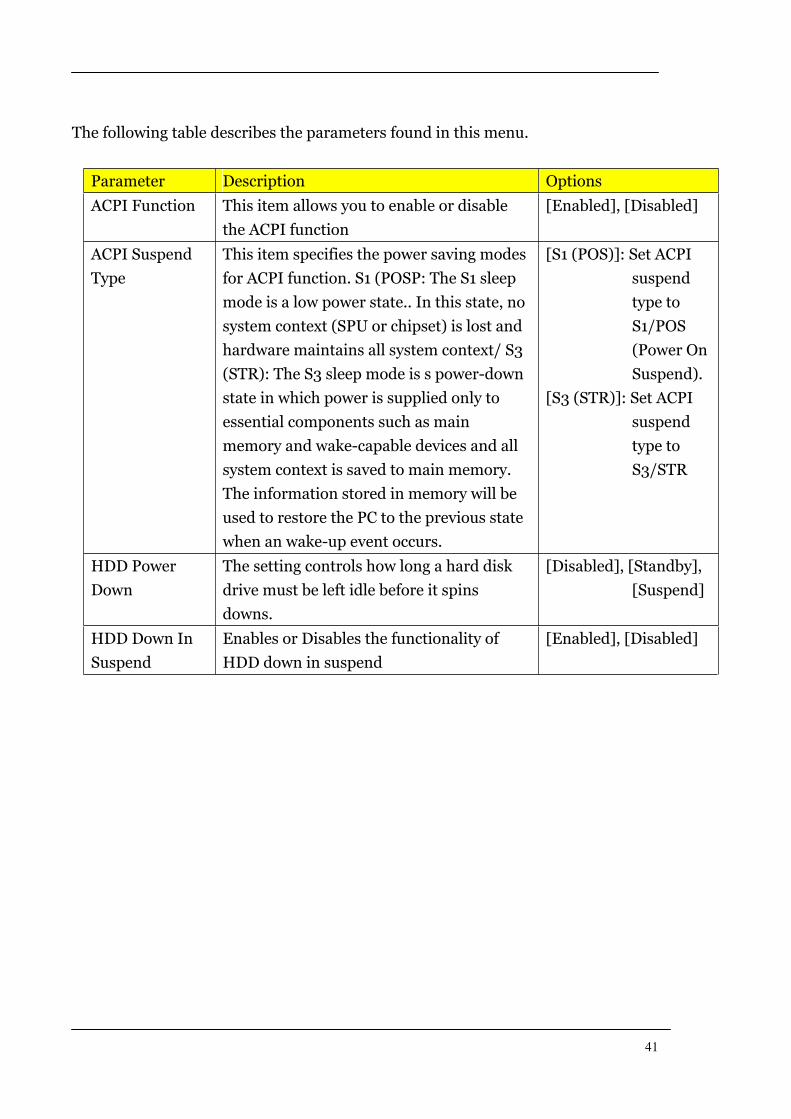
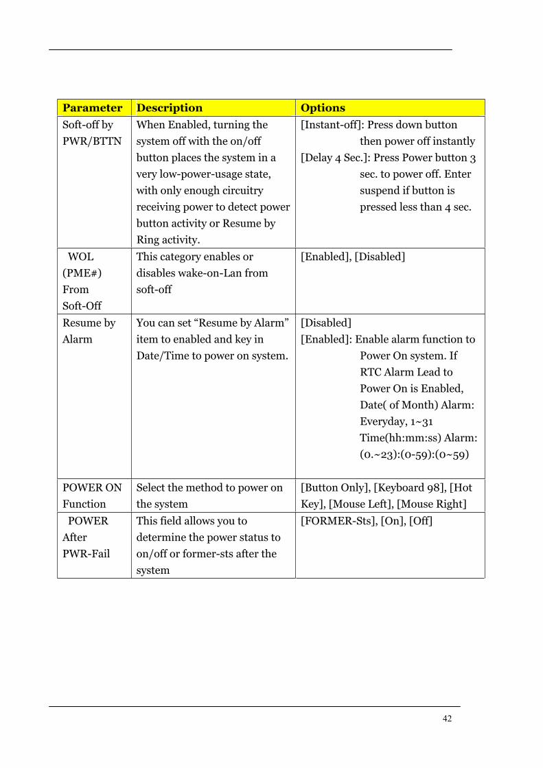
The following table describes the parameters found in this menu.
Parameter Description Options
ACPI Function This item allows you to enable or disable
the ACPI function
[Enabled], [Disabled]
ACPI Suspend
Type
This item specifies the power saving modes
for ACPI function. S1 (POSP: The S1 sleep
mode is a low power state.. In this state, no
system context (SPU or chipset) is lost and
hardware maintains all system context/ S3
(STR): The S3 sleep mode is s power-down
state in which power is supplied only to
essential components such as main
memory and wake-capable devices and all
system context is saved to main memory.
The information stored in memory will be
used to restore the PC to the previous state
when an wake-up event occurs.
[S1 (POS)]: Set ACPI
suspend
type to
S1/POS
(Power On
Suspend).
[S3 (STR)]: Set ACPI
suspend
type to
S3/STR
HDD Power
Down
The setting controls how long a hard disk
drive must be left idle before it spins
downs.
[Disabled], [Standby],
[Suspend]
HDD Down In
Suspend
Enables or Disables the functionality of
HDD down in suspend
[Enabled], [Disabled]
42
Parameter Description Options
Soft-off by
PWR/BTTN
When Enabled, turning the
system off with the on/off
button places the system in a
very low-power-usage state,
with only enough circuitry
receiving power to detect power
button activity or Resume by
Ring activity.
[Instant-off]: Press down button
then power off instantly
[Delay 4 Sec.]: Press Power button 3
sec. to power off. Enter
suspend if button is
pressed less than 4 sec.
WOL
(PME#)
From
Soft-Off
This category enables or
disables wake-on-Lan from
soft-off
[Enabled], [Disabled]
Resume by
Alarm
You can set “Resume by Alarm”
item to enabled and key in
Date/Time to power on system.
[Disabled]
[Enabled]: Enable alarm function to
Power On system. If
RTC Alarm Lead to
Power On is Enabled,
Date( of Month) Alarm:
Everyday, 1~31
Time(hh:mm:ss) Alarm:
(0.~23):(0-59):(0~59)
POWER ON
Function
Select the method to power on
the system
[Button Only], [Keyboard 98], [Hot
Key], [Mouse Left], [Mouse Right]
POWER
After
PWR-Fail
This field allows you to
determine the power status to
on/off or former-sts after the
system
[FORMER-Sts], [On], [Off]
43
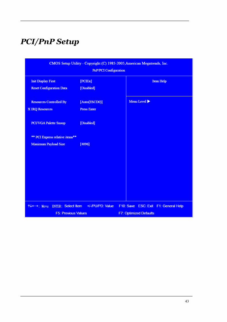
PCI/PnP Setup
44
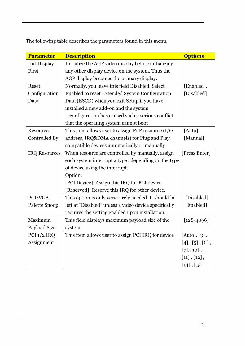
The following table describes the parameters found in this menu.
Parameter Description Options
Init Display
First
Initialize the AGP video display before initializing
any other display device on the system. Thus the
AGP display becomes the primary display.
Reset
Configuration
Data
Normally, you leave this field Disabled. Select
Enabled to reset Extended System Configuration
Data (ESCD) when you exit Setup if you have
installed a new add-on and the system
reconfiguration has caused such a serious conflict
that the operating system cannot boot
[Enabled],
[Disabled]
Resources
Controlled By
This item allows user to assign PnP resource (I/O
address, IRQ&DMA channels) for Plug and Play
compatible devices automatically or manually
[Auto]
[Manual]
IRQ Resources When resource are controlled by manually, assign
each system interrupt a type , depending on the type
of device using the interrupt.
Option:
[PCI Device]: Assign this IRQ for PCI device.
[Reserved]: Reserve this IRQ for other device.
[Press Enter]
PCI/VGA
Palette Snoop
This option is only very rarely needed. It should be
left at “Disabled” unless a video device specifically
requires the setting enabled upon installation.
[Disabled],
[Enabled]
Maximum
Payload Size
This field displays maximum payload size of the
system
[128-4096]
PCI 1/2 IRQ
Assignment
This item allows user to assign PCI IRQ for device [Auto], [3] ,
[4] , [5] , [6] ,
[7], [10] ,
[11] , [12] ,
[14] , [15]
45
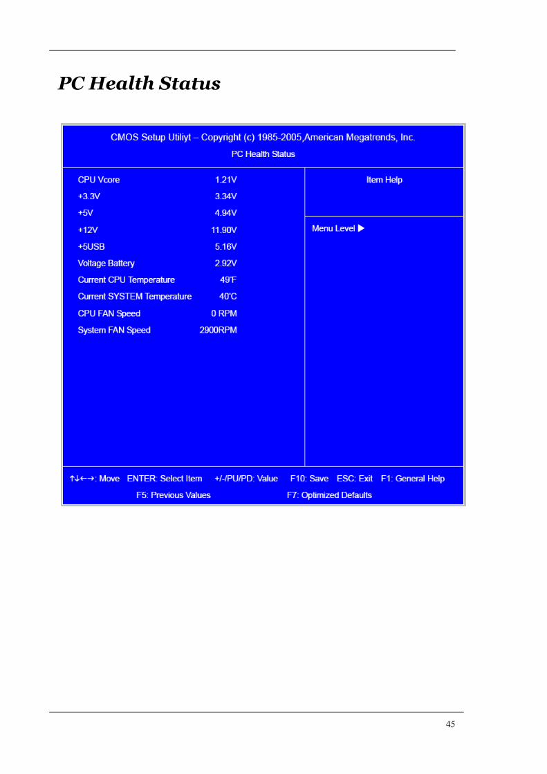
PC Health Status
46
The following table describes the parameters found in this menu:
arameter Description Options
V core Detect system’s voltage status
automatically
CPU Temperature Detect CPU Temperature automatically
CPU/SYSTEM FAN
Speed (RPM)
Detect CPU/SYSTEM Fan Speed Status
automatically
CPU Smart FAN
Control
The item displays the system Smart Fan
Function status. It is always enabled by
system.
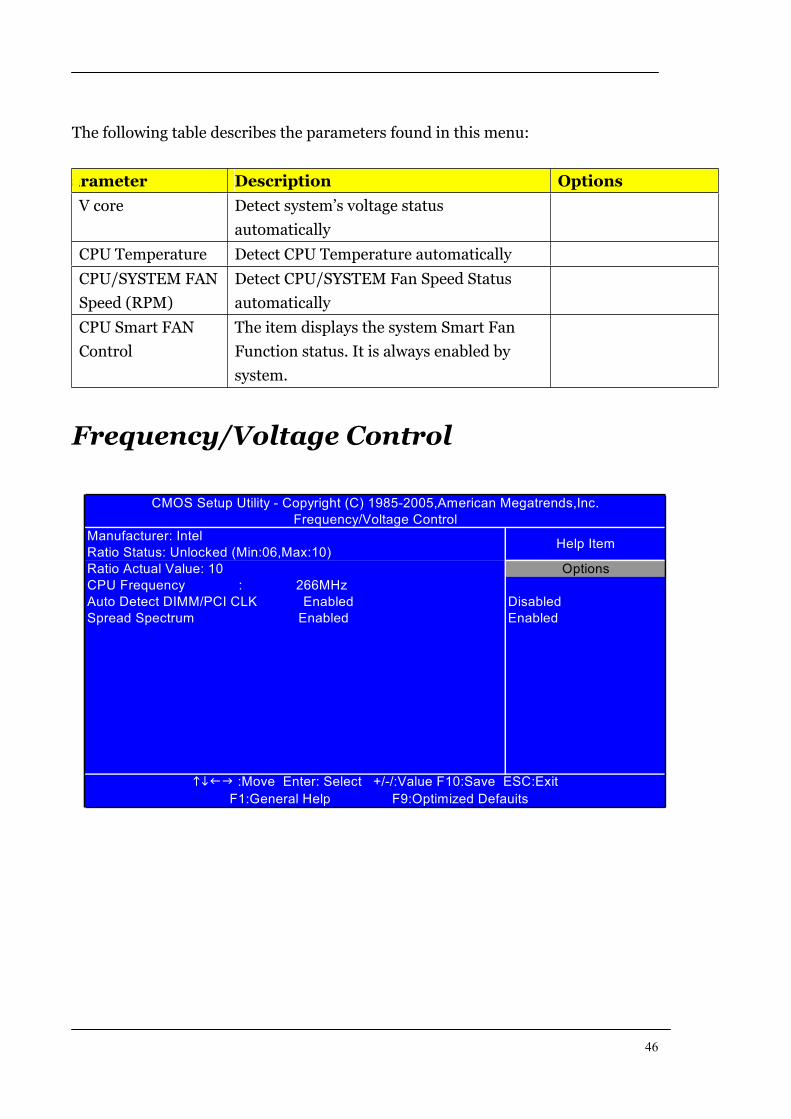
Frequency/Voltage Control
Manufacturer: Intel
Ratio Status: Unlocked (Min:06,Max:10)
CPU Frequency : 266MHz
F1:General Help F9:Optimized Defauits
:Move Enter: Select +/-/:Value F10:Save ESC:Exit
CMOS Setup Utility - Copyright (C) 1985-2005,American Megatrends,Inc.
Frequency/Voltage Control
Ratio Actual Value: 10
Enabled
Auto Detect DIMM/PCI CLK Enabled
Spread Spectrum Enabled
Help Item
Options
Disabled
47
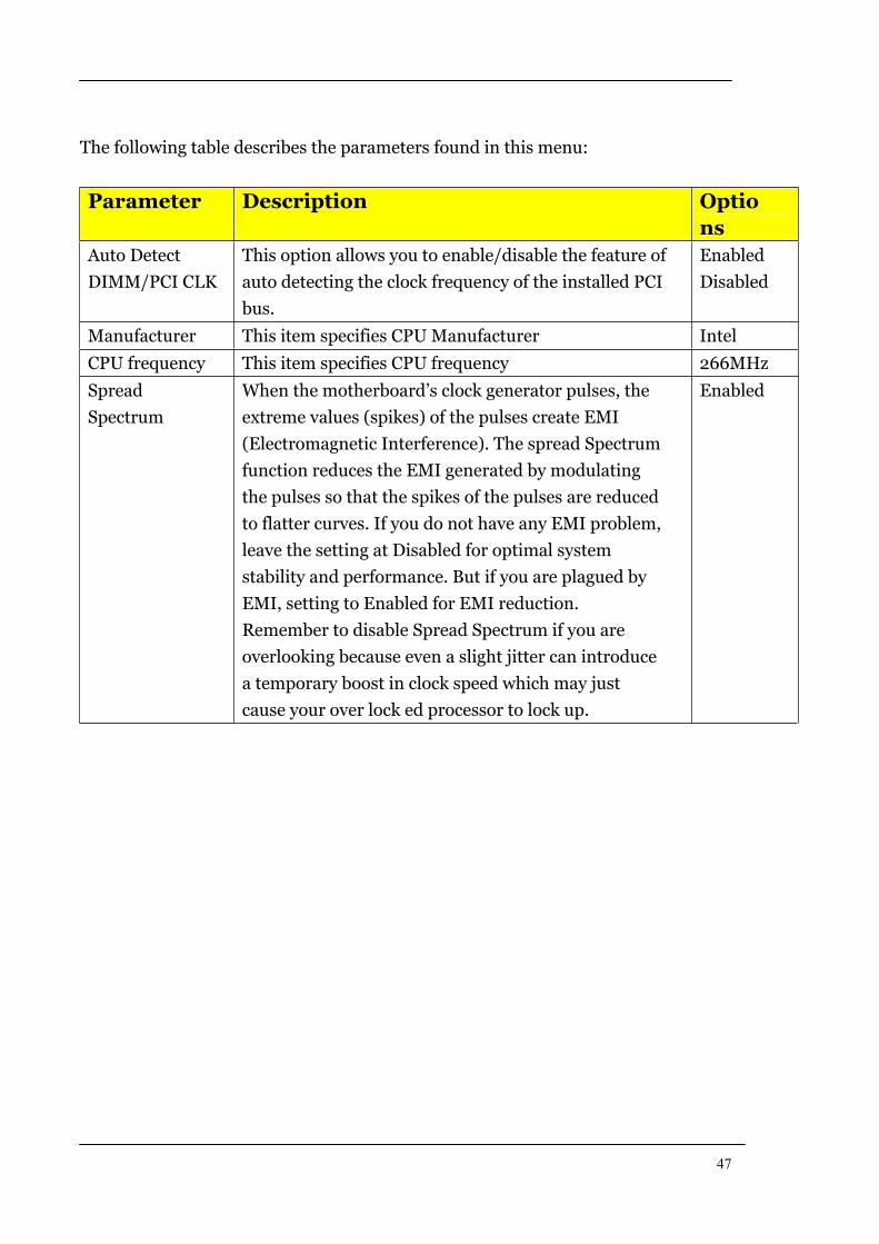
The following table describes the parameters found in this menu:
Parameter Description Optio
ns
Auto Detect
DIMM/PCI CLK
This option allows you to enable/disable the feature of
auto detecting the clock frequency of the installed PCI
bus.
Enabled
Disabled
Manufacturer This item specifies CPU Manufacturer Intel
CPU frequency This item specifies CPU frequency 266MHz
Spread
Spectrum
When the motherboard’s clock generator pulses, the
extreme values (spikes) of the pulses create EMI
(Electromagnetic Interference). The spread Spectrum
function reduces the EMI generated by modulating
the pulses so that the spikes of the pulses are reduced
to flatter curves. If you do not have any EMI problem,
leave the setting at Disabled for optimal system
stability and performance. But if you are plagued by
EMI, setting to Enabled for EMI reduction.
Remember to disable Spread Spectrum if you are
overlooking because even a slight jitter can introduce
a temporary boost in clock speed which may just
cause your over lock ed processor to lock up.
Enabled
48
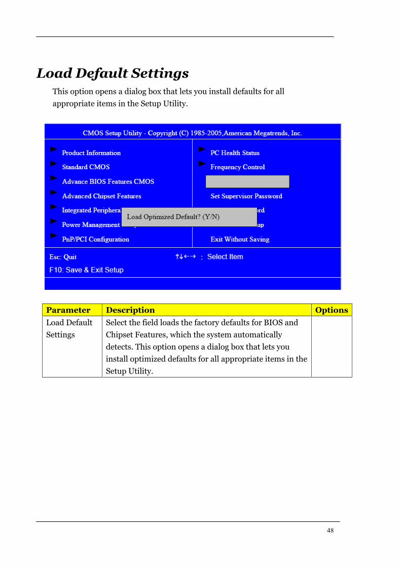
Load Default Settings This option opens a dialog box that lets you install defaults for all
appropriate items in the Setup Utility.
Parameter Description Options
Load Default
Settings
Select the field loads the factory defaults for BIOS and
Chipset Features, which the system automatically
detects. This option opens a dialog box that lets you
install optimized defaults for all appropriate items in the
Setup Utility.
49
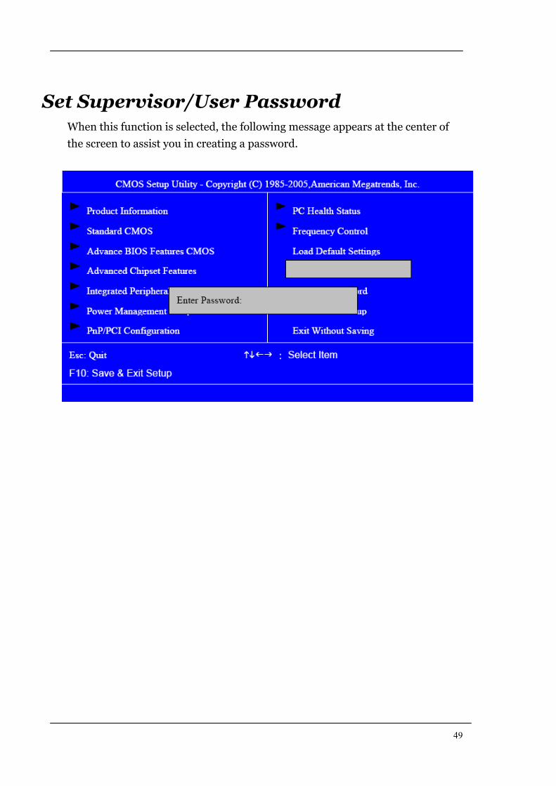
Set Supervisor/User Password When this function is selected, the following message appears at the center of
the screen to assist you in creating a password.
50
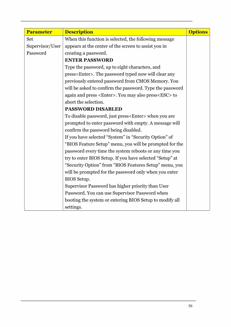
Parameter Description Options
Set
Supervisor/User
Password
When this function is selected, the following message
appears at the center of the screen to assist you in
creating a password.
ENTER PASSWORD
Type the password, up to eight characters, and
press<Enter>. The password typed now will clear any
previously entered password from CMOS Memory. You
will be asked to confirm the password. Type the password
again and press <Enter>. You may also press<ESC> to
abort the selection.
PASSWORD DISABLED
To disable password, just press<Enter> when you are
prompted to enter password with empty. A message will
confirm the password being disabled.
If you have selected “System” in “Security Option” of
“BIOS Feature Setup” menu, you will be prompted for the
password every time the system reboots or any time you
try to enter BIOS Setup. If you have selected “Setup” at
“Security Option” from “BIOS Features Setup” menu, you
will be prompted for the password only when you enter
BIOS Setup.
Supervisor Password has higher priority than User
Password. You can use Supervisor Password when
booting the system or entering BIOS Setup to modify all
settings.
51
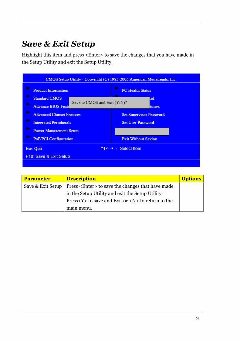
Save & Exit SetupHighlight this item and press <Enter> to save the changes that you have made in
the Setup Utility and exit the Setup Utility.
Parameter Description Options
Save & Exit Setup Press <Enter> to save the changes that have made
in the Setup Utility and exit the Setup Utility.
Press<Y> to save and Exit or <N> to return to the
main menu.
52
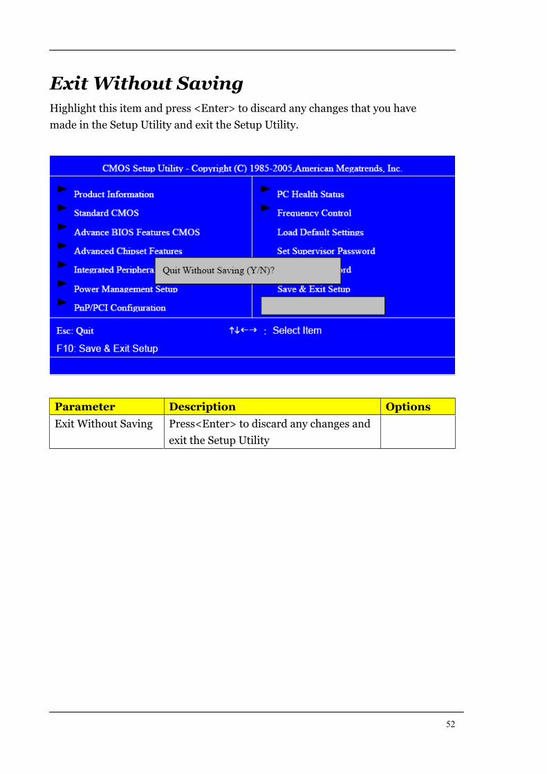
Exit Without SavingHighlight this item and press <Enter> to discard any changes that you have
made in the Setup Utility and exit the Setup Utility.
Parameter Description Options
Exit Without Saving Press<Enter> to discard any changes and
exit the Setup Utility

53
Machine Disassembly and Replacement
To disassemble the computer, you need the following tools:
Wrist grounding strap and conductive mat for preventing
electrostatic discharge.
Wire cutter.
Phillips screwdriver (may require different size).
NOTE: The screws for the different components vary in size. During the
disassembly process, group the screws with the corresponding
components to avoid mismatches when putting back the
components.

54
General Information
Before You Begin
Before proceeding with the disassembly procedure, make sure that you
do the following:
1. Turn off the power to the system and all peripherals.
2. Unplug the AC adapter and all power and signal cables from the
system

55
Disassembly Procedure
This section tells you how to disassemble the system when you need to
perform system service. Please also refer to the disassembly video, if
available.
CAUTION: Before you proceed, make sure you have turned off the
system and all peripherals connected to it.
56
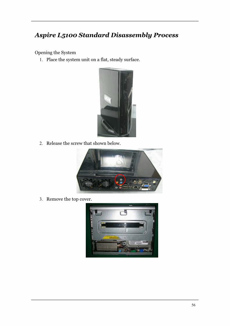
Aspire L5100 Standard Disassembly Process
Opening the System
1. Place the system unit on a flat, steady surface.
2. Release the screw that shown below.
3. Remove the top cover.

57
4. As shown pull three button up.
5. Take the belt shown as below. Release this screw first
6. Detach ODD & HDD data and power cable.
7. Detach HDD date and power cable.
HDD power CABLE
HDD data CABLE
ODD cable HDD cable
58
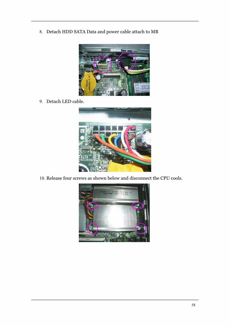
8. Detach HDD SATA Data and power cable attach to MB
9. Detach LED cable.
10. Release four screws as shown below and disconnect the CPU cools.
59
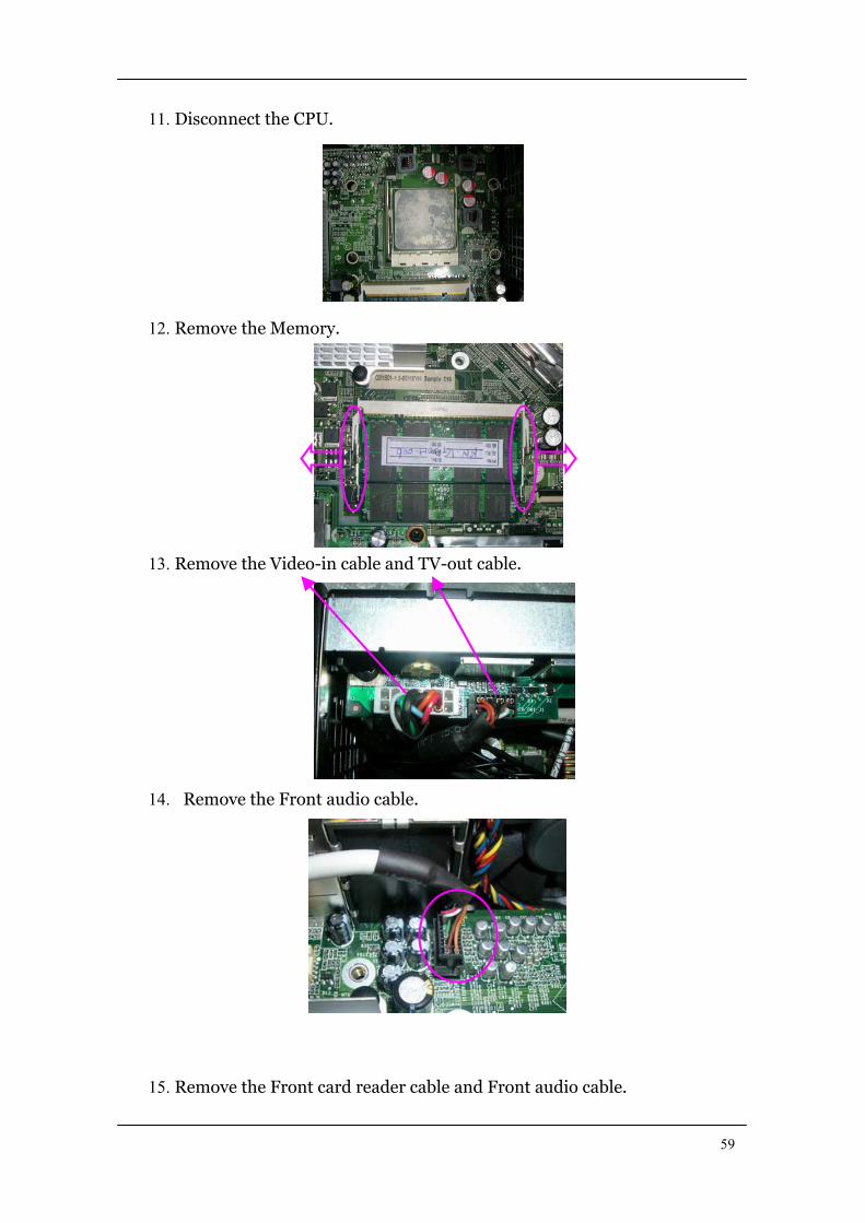
11. Disconnect the CPU.
12. Remove the Memory.
13. Remove the Video-in cable and TV-out cable.
14. Remove the Front audio cable.
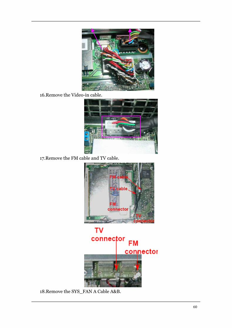
15. Remove the Front card reader cable and Front audio cable.
60
16.Remove the Video-in cable.
17.Remove the FM cable and TV cable.
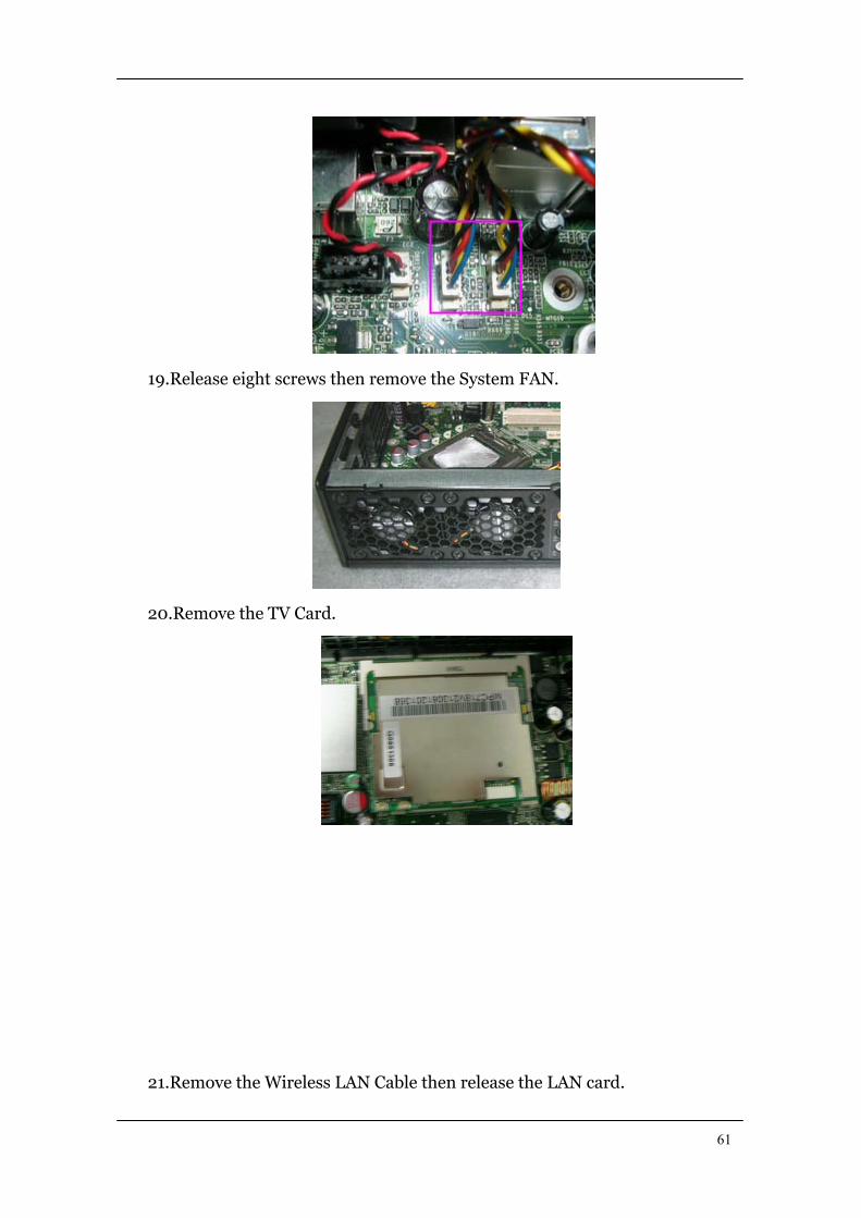
18.Remove the SYS_FAN A Cable A&B.
61
19.Release eight screws then remove the System FAN.
20.Remove the TV Card.
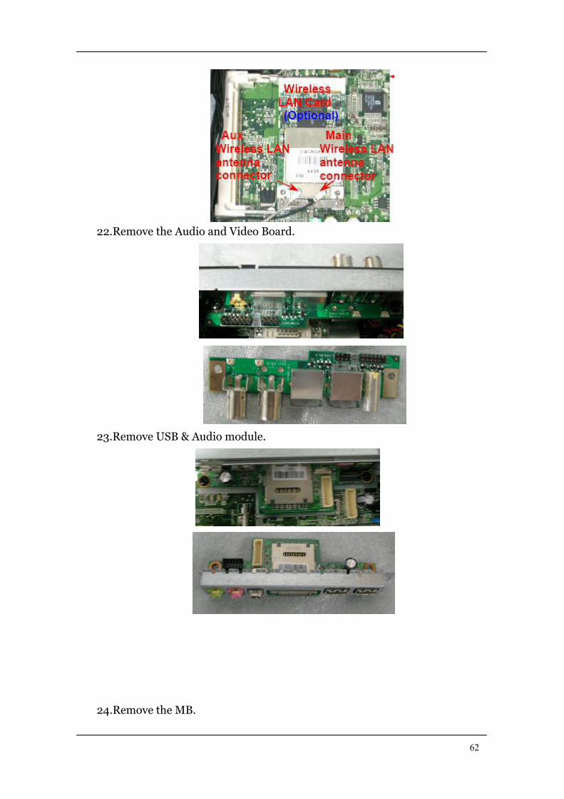
21.Remove the Wireless LAN Cable then release the LAN card.
62
22.Remove the Audio and Video Board.
23.Remove USB & Audio module.
24.Remove the MB.

63
64
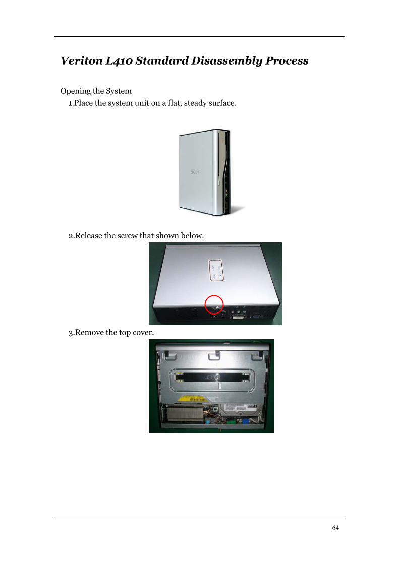
Veriton L410 Standard Disassembly Process
Opening the System
1.Place the system unit on a flat, steady surface.
2.Release the screw that shown below.
3.Remove the top cover.
65
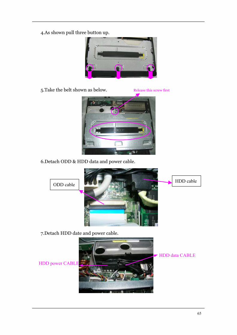
4.As shown pull three button up.
5.Take the belt shown as below. Release this screw first
6.Detach ODD & HDD data and power cable.
7.Detach HDD date and power cable.
HDD power CABLE
HDD data CABLE
ODD cable HDD cable

66
8.Detach HDD SATA Data and power cable attach to MB
9.Detach LED cable.
10.Release four screws as shown below and disconnect the CPU cools.
67
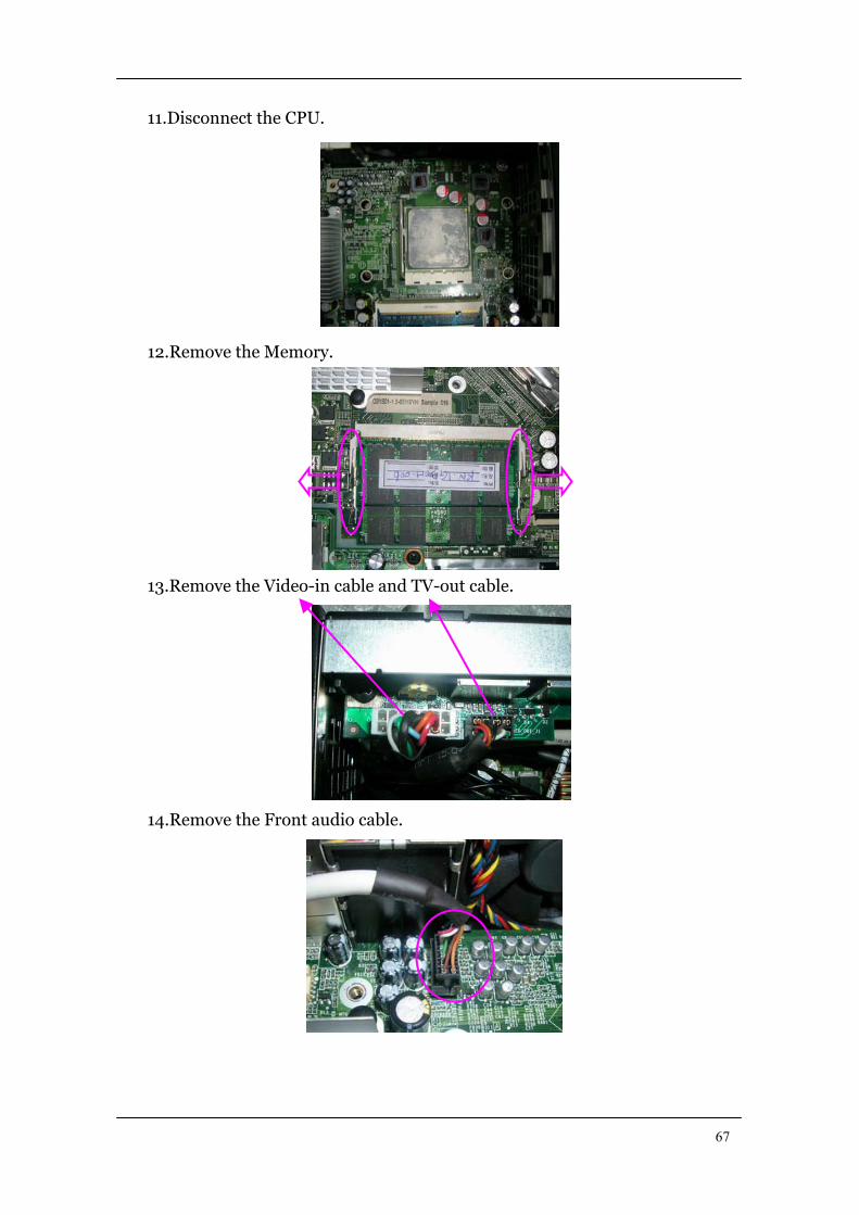
11.Disconnect the CPU.
12.Remove the Memory.
13.Remove the Video-in cable and TV-out cable.
14.Remove the Front audio cable.
68
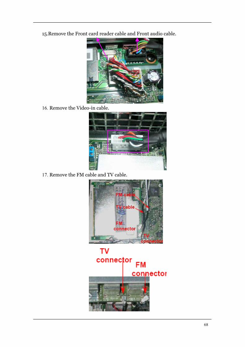
15.Remove the Front card reader cable and Front audio cable.
16. Remove the Video-in cable.
17. Remove the FM cable and TV cable.
69
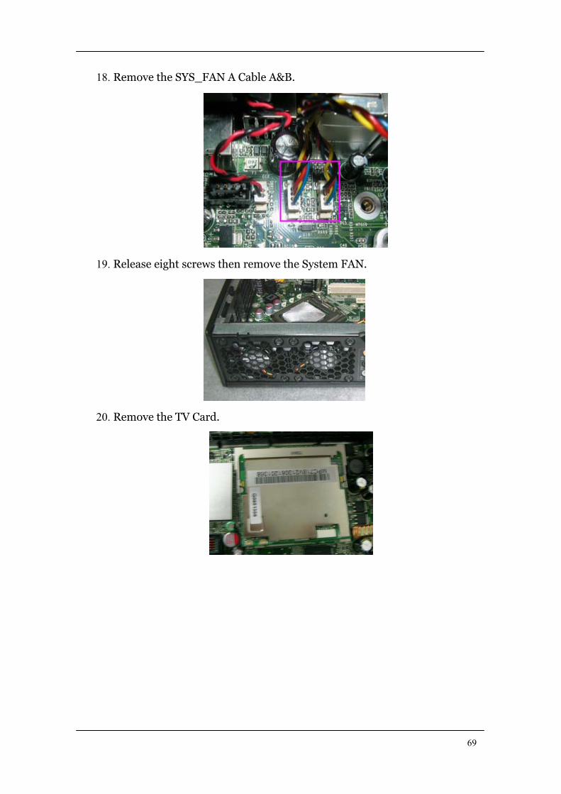
18. Remove the SYS_FAN A Cable A&B.
19. Release eight screws then remove the System FAN.
20. Remove the TV Card.
70
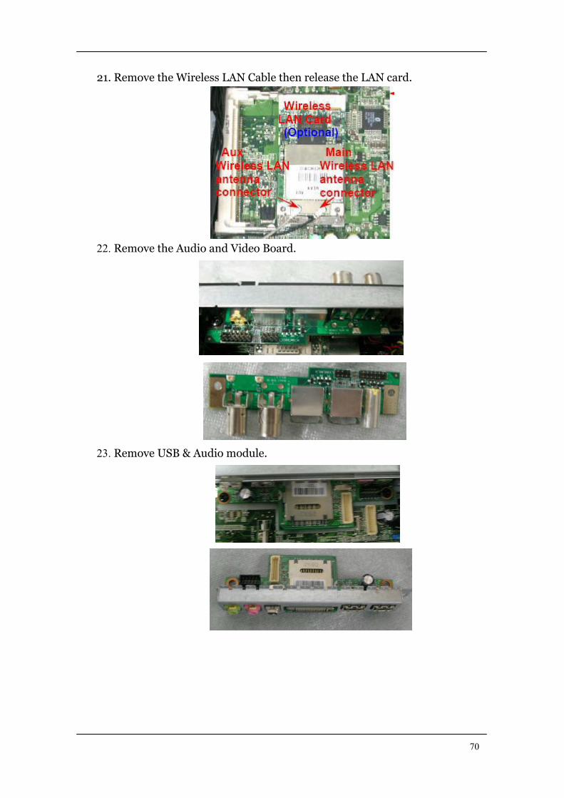
21. Remove the Wireless LAN Cable then release the LAN card.
22. Remove the Audio and Video Board.
23. Remove USB & Audio module.
71
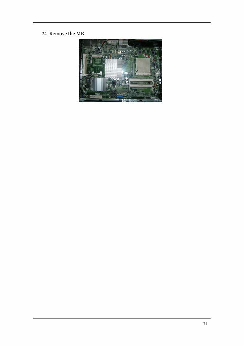
24. Remove the MB.

72
TroubleshootingPlease refer to generic troubleshooting guide for troubleshooting information relating to
following topics:
Power-On Self-Test (POST)
POST Check Points
POST Error Messages List
Error Symptoms List
73
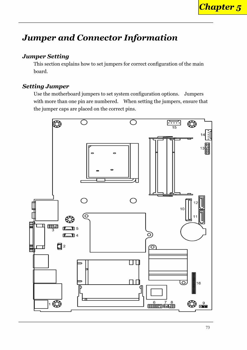
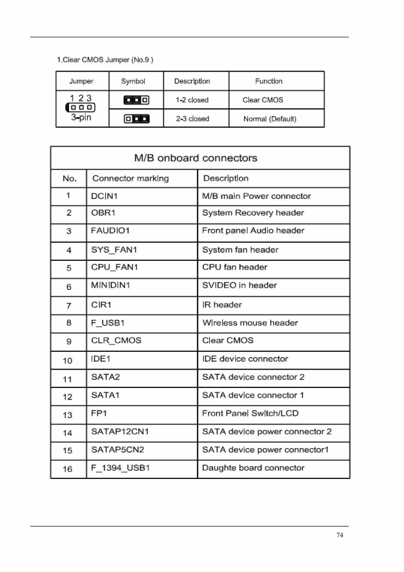
Jumper and Connector Information
Jumper Setting
This section explains how to set jumpers for correct configuration of the main
board.
Setting Jumper
Use the motherboard jumpers to set system configuration options. Jumpers
with more than one pin are numbered. When setting the jumpers, ensure that
the jumper caps are placed on the correct pins.
74

75
FRU (Field Replaceable Unit) List This chapter gives you the FRU (Field Replaceable Unit) listing in global configurations of
Aspire L5100/Veriton L410. Refer to this chapter whenever ordering for parts to repair
or for RMA (Return Merchandise Authorization).
NOTE: Please note WHEN ORDERING FRU PARTS, that you should check the most
up-to-date information available on your regional web or channel
(http://aicsl.acer.com.tw/spl/, if you do not own a specific account, you can still
access the system with guest; guest). For whatever reasons a part number change is
made, it will not be noted in the printed Service Guide. For ACER-AUTHORIZED
SERVICE PROVIDERS, your Acer office may have a DIFFERENT part number
code to those given in the FRU list of this printed Service Guide. You MUST use the
local FRU list provided by your regional Acer office to order FRU parts for repair
and service of customer machines.
76
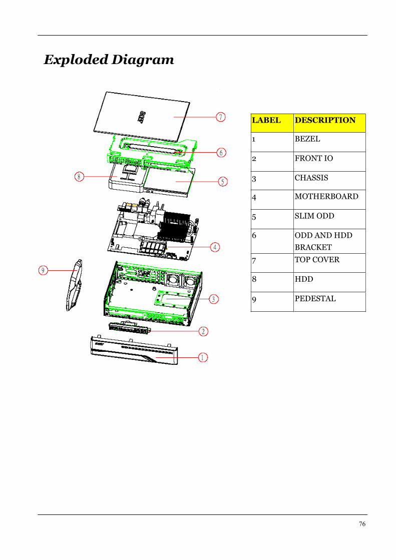
Exploded Diagram
LABEL DESCRIPTION
1 BEZEL
2 FRONT IO
3 CHASSIS
4 MOTHERBOARD
5 SLIM ODD
6 ODD AND HDD
BRACKET
7 TOP COVER
8 HDD
9 PEDESTAL
77
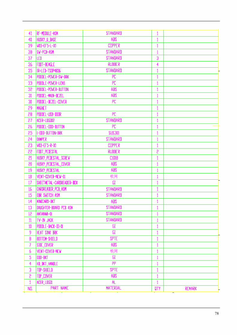
78
79
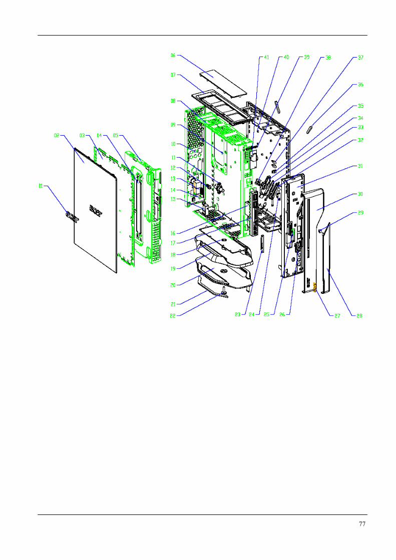
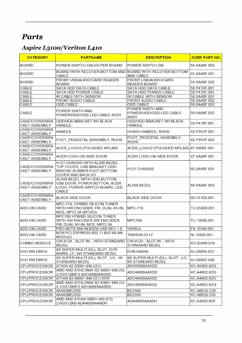
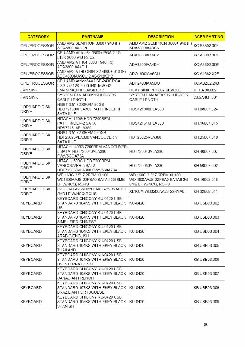
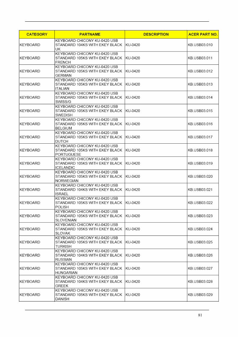
Parts
Aspire L5100/Veriton L410
80
81
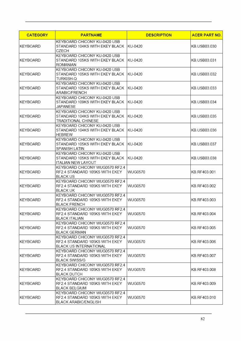
82
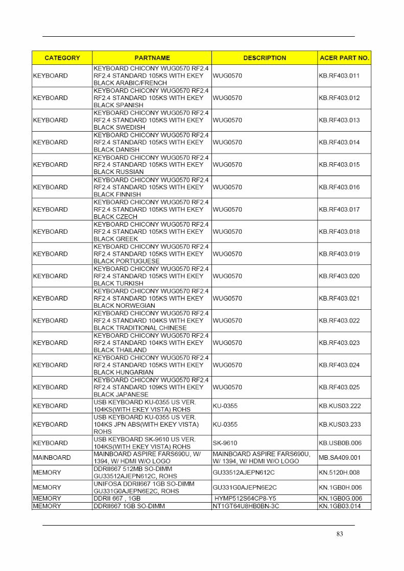
83
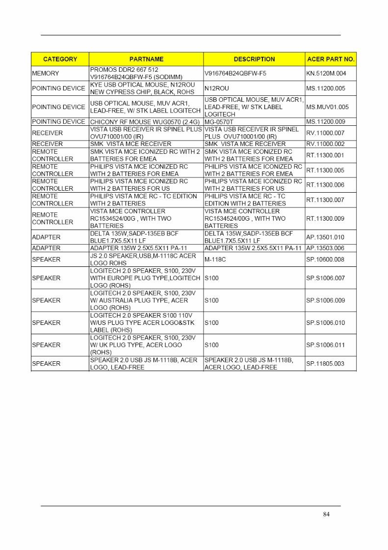
84


