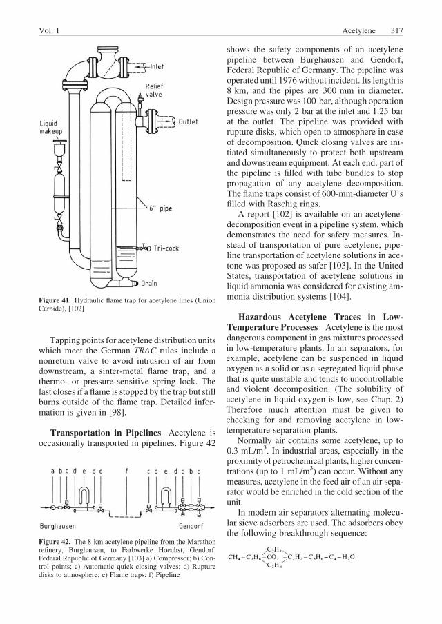
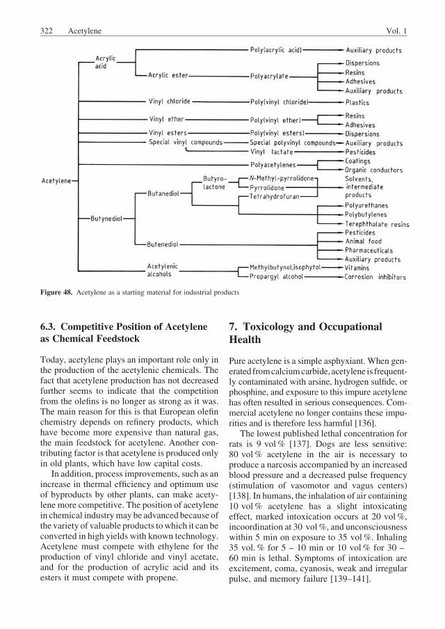
Ó 2012 Wiley-VCH Verlag GmbH & Co. KGaA, Weinheim Acetylene PETER PA ¨ SSLER, BASF Aktiengesellschaft, Ludwigshafen, Germany WERNER HEFNER, BASF Aktiengesellschaft, Ludwigshafen, Germany KLAUS BUCKL, Linde AG, H€ ollriegelskreuth, Germany HELMUT MEINASS, Linde AG, H€ ollriegelskreuth, Germany ANDREAS MEISWINKEL, Linde AG, Linde Engineering Division, Pullach, Germany HANS-JU ¨ RGEN WERNICKE, Linde AG, H€ ollriegelskreuth, Germany G€ uNTER EBERSBERG, Degussa-H€ uls AG, Marl, Germany RICHARD M€ uLLER, Degussa-H€ uls AG, Marl, Germany JU ¨ RGEN BA ¨ SSLER, Uhde GmbH, Dortmund, Germany HARTMUT BEHRINGER, Hoechst Aktiengesellschaft, Werk Knapsack, Germany DIETER MAYER, Hoechst Aktiengesellschaft, Pharma-Forschung, Toxikologie, Frankfurt, Germany 1. Introduction...................... 277 2. Physical Properties ................ 278 3. Chemical Properties ............... 280 3.1. Industrially Important Reactions ...... 281 3.2. Other Reactions; Derivatives ......... 284 4. Production ....................... 284 4.1. Thermodynamic and Kinetic Aspects .. 284 4.2. Partial Combustion Processes ........ 286 4.2.1. BASF Process (Sachsse-Bartholome) .... 287 4.2.2. Other Partial Combustion Processes ..... 293 4.2.3. Submerged Flame Process ............ 293 4.2.4. Partial Combustion Carbide Process ..... 296 4.3. Electrothermic Processes ............ 296 4.3.1. Production from Gaseous and/or Gasified Hydrocarbons (H€ uls Arc Process) ....... 298 4.3.2. Production from Liquid Hydrocarbons (Plasma Arc Process) ..... 301 4.3.3. Production from Arc Coal Process) ..... 302 4.3.4. Production from Calcium Carbide ...... 303 4.3.4.1. Wet Generators .................... 305 4.3.4.2. Dry Generators .................... 306 4.3.4.3. Acetylene Purification ............... 307 4.4. Other Cracking Processes ........... 308 4.4.1. Thermal Cracking By Heat Carriers ..... 308 4.4.2. Acetylene as a Byproduct of Steam Cracking 310 5. Safety Precautions, Transportation, and Storage.......................... 312 5.1. General Safety Factors and Safety Measures ........................ 312 5.2. Acetylene Storage in Cylinders ....... 318 6. Uses and Economic Aspects .......... 319 6.1. Use in Metal Processing ............. 319 6.2. Use as Raw Material in Chemical Industry 321 6.3. Competitive Position of Acetylene as Chemical Feedstock ................ 322 7. Toxicology and Occupational Health ... 322 References ....................... 323 1. Introduction Acetylene [74-86-2] is the simplest hydrocarbon with a triple bond. In the days before oil gained widespread acceptance as the main feedstock of chemical industry, acetylene was the predomi- nant building block of industrial organic chem- istry. The calcium carbide process was the sole route for acetylene production until 1940, when thermal cracking processes using methane and other hydrocarbons were introduced. At first, these processes used an electric arc; then, in the 1950s, partial oxidation and regenerative pro- cesses were developed. However, along with the expansion of the petroleum industry there was a changeover from coal chemistry to petrochemistry, in the 1940s in the United States and in the 1950s in Europe. As a consequence, acetylene lost its competitive position to the much cheaper and more readily available naphtha-derived ethylene and other olefins. This competition between acetylene and DOI: 10.1002/14356007.a01_097.pub4
Transcript
� 2012 Wiley-VCH Verlag GmbH & Co. KGaA, Weinheim
Article No : a01_097
Acetylene
PETER PASSLER, BASF Aktiengesellschaft, Ludwigshafen, Germany
WERNER HEFNER, BASF Aktiengesellschaft, Ludwigshafen, Germany
KLAUS BUCKL, Linde AG, H€ollriegelskreuth, Germany
HELMUT MEINASS, Linde AG, H€ollriegelskreuth, Germany
ANDREAS MEISWINKEL, Linde AG, Linde Engineering Division, Pullach, Germany
Acetylene [74-86-2] is the simplest hydrocarbonwith a triple bond. In the days before oil gainedwidespread acceptance as the main feedstock ofchemical industry, acetylene was the predomi-nant building block of industrial organic chem-istry. The calcium carbide process was the soleroute for acetylene production until 1940, whenthermal cracking processes using methane andother hydrocarbons were introduced. At first,
these processes used an electric arc; then, in the1950s, partial oxidation and regenerative pro-cesses were developed.
However, along with the expansion of thepetroleum industry there was a changeover fromcoal chemistry to petrochemistry, in the 1940s intheUnited States and in the 1950s in Europe. As aconsequence, acetylene lost its competitiveposition to the much cheaper and more readilyavailable naphtha-derived ethylene and otherolefins. This competition between acetylene and
DOI: 10.1002/14356007.a01_097.pub4
ethylene as feedstocks for chemical industry hasbeen much discussed in the 1960s and 1970s[1, 2]. The few hopes, such as BASF’s contribu-tion to the submerged flame process, Hoechst’scrude oil cracking (HTP), or H€uls’ plasma pro-cess, have not halted the clear trend towardethylene as a basic chemical. With the first oilprice explosion in 1973, the development ofcrude cracking processes suffered a setback, andthe new processes, such as the Kureha/UnionCarbide process, DOW’s PCC process (PCC ¼partial combustion cracking), or the Kureha/Chiyoda/Union Carbide ACR process (ACR ¼advanced cracking reactor), raise little hope for acomeback of acetylene chemistry. Acetyleneproduction peaked in the United Statesat 480000 t in the 1960s, and in Germany at350000 t in the early 1970s [3]. Since then,acetylene production has decreased steadily. Inboth countries the losses were principally incarbide-derived acetylene; in fact, Germany hasproduced acetylene for chemical purposesalmost exclusively from natural gas and petro-chemical sources since 1975.
All acetylene processes, including carbideprocesses, are high-temperature processes,requiring a large amount of energy. They differessentially only in the manner in which thenecessary energy is generated and transferred.They can be classified into three groups: partialcombustion processes, electrothermic processes,and processes using heat carriers. Finally, the useof byproduct acetylene from olefin plants iseconomically viable in many cases. For eachgroup of acetylene processes several variantshave been developed using various feedstocksand techniques. Today, only three processesremain for the commercial production of acety-lene: the calcium carbide route, in which thecarbide is produced electrically, the arc process,and the partial oxidation of natural gas. Otheronce popular processes have become uneconom-ical as the price of naphtha has increased.
Some processes were shelved in the experi-mental or pilot-plant stage as the importance ofacetylene declined.However, other new process-es involving the use of coal, sulfur-containingcrude oil, or residues as feedstocks for acetyleneproduction are in the pilot-plant stage.
However, the position of acetylene in chemi-cal industry may improve because of the varietyof valuable products to which acetylene can be
converted with known technology and highyields.
2. Physical Properties
Due to the carbon–carbon triple bond and thehigh positive energy of formation, acetylene is anunstable, highly reactive unsaturated hydrocar-bon. The C – C triple bond and C – H s bondlengths are 0.1205 and 0.1059 nm, respectively.For the electronic structure of acetylene and amolecular orbital description, see [4]. The acidityof acetylene (pKa ¼ 25) permits the formation ofacetylides (see Section 3.2). For comparison thepKa value of ethylene is 44 and that of acetone 20.
Under normal conditions acetylene is a color-less, nontoxic but narcotic gas; it is slightlylighter than air. The main physical properties arelisted in Table 1. The critical temperature andpressure are 308.32 K and 6.139 MPa. The triplepoint at 128.3 kPa is 192.4 K. The vapor pres-sure curve for acetylene is shown in Figure 1.
Table 1. Physical properties of acetylene [5–8]
Molecular mass 26.0379
Critical temperature 308.32 K (35.17 �C)Critical pressure 6.139 MPa
Critical volume 0.113 m3/kmol
Triple point 192.4 K (� 80.75 �C)Triple point pressure 128.3 kPa
Normal sublimation point
and normal boiling point
189.15 K (� 84.0 �C)
Crystal transition point 133.0 K (� 140.15 �C)Enthalpy of transition 2.54 kJ/mol
Density 760.2 kg/m3 (131 K)
764.3 kg/m3 (141 K)
Density (liquid C2H2) 465.2 kg/m3 (273.15 K)
Density (gaseous
C2H2 at 1 bar)
1.095 kg/m3 (288.15 K)
Molecular volume
(0 �C, 1.013 bar)
22.223 m3/kmol
Enthalpy of vaporization
(calculated)
10.65 kJ/mol (273.15 K)
Enthalpy of sublimation 21.168 kJ/mol (5.55 K)
Enthalpy of formation 227.5 � 1.0 kJ/mol (298.15 K)
The formation of acetylene is strongly endother-mic (DHf ¼ þ 227.5 kJ/mol at 298.15 K).
Self-decomposition can be initiated whencertain pressure limits above atmospheric pres-sure are exceeded (for details see Section 5.1).
The crystalline structure of solid acetylenechanges at � 140.15 �C from a cubic to anorthorhombic phase. The heat of reaction forthis phase change is 2.54 kJ/mol [7]; two differ-ent values for the enthalpy of fusion are reportedin the literature [5, 6]. Figure 2 shows the densityof liquid and gaseous acetylene.
Details about flame properties, decomposi-tion, and safety measures are given in Chapter 5.
Solubility coefficients of acetylene in organicsolvents are listed in Table 2 [9]. Further solu-bility data are available as Bunsen absorptioncoefficients a (20 �C, m3 (STP) m�3 atm�1), assolubilities (g/kg of solvent), and for differentpressures (see [10]). The solubilities of acetyleneat infinite dilution are shown in Figure 3 forwater, methanol, DMF, and N-methyl-2-pyrro-lidone (NMP) [872-50-4]. Figure 4 shows thesolubility of acetylene in acetone for variouspartial pressures and temperatures. While at20 �C and 1.013 bar 27.9 g (51.0 g) acetylenecan be dissolved in 1 kg acetone (DMF) at 20.26
bar 689.0 g (628.0 g) can be dissolved in thesame amount of solvent [129]. The heat of solu-tion depends on the concentration of acetylene inthe solvent: dissolving 0.5 kg of acetylene in1 kg of solvent generates 293 kJ for acetone and335 kJ for DMF. For details on the influence of
Figure 1. Vapor pressure of acetylene [5, 6]
Figure 2. Density of acetylene vapor (at 1.013 bar) andliquid
Table 2. Solubility coefficients of C2H2 in various solvents (in mol
kg�1 bar�1) [9]
Solvent C2H2 pressure,
bar
� 20 �C 25 �C
Methanol 0.98 1.979 0.569
Ethanol 0.98 0.851 0.318
n-Butanol 0.245 – 0.657 0.237
1,2-Dichloroethane 0.4–1.05 0.569 0.218
Carbon tetrachloride 0.98 0.164 0.075
n-Hexane 6.90 0.523 0.264
n-Octane 0.196 – 14.71 0.205 0.146
(0� C)
Benzene 0.98 0.225
Toluene 0.98 0.619 0.214
Xylene (tech.) 0.98 0.528 0.189
4-Methyl-1,3-dioxolan-2-one
(propylene carbonate)
0.98 1.137 0.350
Tri-n-butylphosphate 0–0.4 2.366 0.614
Methyl acetate 0.98 2.912 0.878
Triethylene glycol 0.98 0.205
Acetone 0.98 4.231 1.069
N-Methyl-2-pyrrolidone 0.98 5.687 1.319
N,N-Dimethylformamide 0.98 5.096 1.501
Dimethyl sulfoxide 0.98 1.001
Ammonia 0.98 7.052 2.229
Vol. 1 Acetylene 279
water, of partial pressure, and deviations fromHenry’s law, see [9, 10]. Only at temperaturesabove 25 �C and pressures < ca. 10 bar thesolubility of acetylene in acetone followsHenry’s law. At higher pressures the solubilityincreasesmore rapidly than predicted byHenry’slaw [130]. The temperature dependence of thesolubility of acetylene in DMF at infinite dilutionis compared with those of ethylene and ethane inFigure 5 (see also [9, 11] for selectivities).
The solubility of acetylene inwater at 25 �C is0.042 mol L�1 bar�1. Under pressure of acety-lene (e.g., > 0.5 MPa at 0 �C) and at tempera-tures between 268 and 283 K, waxy hydrates ofthe composition C2H2 � (H2O)�5.8 are formed
[9, 10]. The hydrates can block equipment; shockwaves may initiate self-decomposition.
Liquid oxygen dissolves only traces of acety-lene (5.5 ppm at 90 K [12]); the solubilities ofethylene and ethane in oxygen are much higher(factor of 350 and 2280, respectively). The pre-purification of the process air in air separationplants with molecular sieves removes acetyleneto < 1 ppb provided there is no breakthrough ofcarbon dioxide. This fact guarantees a safe oper-ation of the downstream equipment [13].
Typical adsorption isotherms of acetyleneare shown in Figure 6 for molecular sieves,activated carbon and silica gel at 25 �C [14];additional information for activated carbon issummarized in [15].
3. Chemical Properties
Because of its strongly unsaturated character andhigh positive free energy of formation, acetylenereacts readily with many elements and com-pounds. As a result acetylene is used as rawmaterial for a great variety of substances. Impor-tant are addition reactions, hydrogen replace-ments, polymerization, and cyclization.
Figure 3. Solubility of acetylene in various solvents atinfinite dilution
Figure 4. Solubility of acetylene in acetone [9]
Figure 5. Solubility of C2 hydrocarbons in DMF at infinitedilution
280 Acetylene Vol. 1
Acetylene is more susceptible to nucleophilicattack than, for instance, ethylene. In addition,the polarized C-H bond makes acetylene acidic(pKa ¼ 25) [16]. Because of this acidity, acety-lene is very soluble in basic solvents [17, 18],forming hydrogen bonds with them [19]. There-fore, the vapor pressures of such solutions cannotbe described by Raoult’s law [20].
The development of the acetylene pressurereactions by W. REPPE (1892 – 1969), BASFLudwigshafen (Germany) [21–23] beganmodernacetylene chemistry. Themost interesting groupsof reactions are vinylation, ethynylation, carbon-ylation, and cyclic and linear polymerization.
3.1. Industrially Important Reactions
Vinylation Reactions and Products [24].Vinylation is the addition of compounds with amobile hydrogen atom, such as water, alcohols,thiols, amines, and organic and inorganic acids,to acetylene to form vinyl compounds chieflyused for polymerization.
The two types of vinylation reactions areheterovinylation and the less usual C vinylation.In the former, the hydrogen atom originates fromthe heteroatoms O, S, and N, whereas C vinyla-tion occurs when the mobile hydrogen atom isdirectly bound to a carbon atom. Examples of Cvinylation are dimerization and trimerization ofacetylene, the synthesis of acrylonitrile fromacetylene and hydrogen cyanide, and the additionof acetylene to unsaturated hydrocarbons withactivated hydrogen atoms, such as cyclopenta-diene, indene, fluorene, and anthracene.
The first industrial vinylation products wereacetaldehyde, vinyl chloride, and vinyl acetate.Many other products followed.
Some examples of industrial vinylation pro-cesses are given below:
Acetaldehyde [75-07-0] (! Acetaldehyde):
HC � CHþH2O!CH3CHO
Catalyst: acidic solutions of mercury salts,such as HgSO4 in H2SO4 . Liquid-phase reactionat 92 �C.
where R is an alkyl group. Reaction temperatureof 120 – 150 �C; pressure high enough to avoidboiling the alcohol used, e.g., 2 MPa with meth-anol to produce methyl vinyl ether (acetylenepressure reaction).
Figure 6. Adsorption isotherms for acetylene on 4A and 5Amolecular sieves, activated carbon, and silica gel at 25 �C[14]
Vol. 1 Acetylene 281
Catalyst: zinc or cadmium salts. Liquid-phasereaction.
Vinyl Amines, vinylation with zinc or cad-mium compounds as catalyst:
R1R2NHþHC � CH!R1R2N�CH ¼ CH2
where R1 and R2 are alkyl groups.N-Vinylcarbazole [1484-13-5], vinylation of
carbazole in a solvent, e.g., N-methylpyrroli-done, at 180 �C.
Vinylation of Ammonia, complex Co and Nisalts as catalysts, reaction temperature of 95 �C:
Vinylation of Acid Amides, potassium salt ofthe amide as catalyst:
HC � CHþRCO�NH2!RCO�NH�CH ¼ CH2
N-Vinyl-2-pyrrolidone [88-12-0], vinyla-tion of 2-pyrrolidone with the potassium salt ofthe pyrrolidone as catalyst.
Acrylonitrile [107-13-1], C-vinylation ofHCN in aqueous hydrochloric acid with CuCland NH4Cl catalyst:
HC � CHþHCN!H2C ¼ CH�CN
Ethynylation Reactions and Products[25]. Ethynylation is the addition of carbonylcompounds to acetylene with the triple bondremaining intact. REPPE found that heavy metalacetylides (see Section 3.2), especially the cop-per(I) acetylide of composition Cu2C2 � 2 H2O �2 C2H2 , are suitable catalysts for the reaction ofaldehydes with acetylene. Alkaline catalysts aremore effective than copper acetylide for theethynylation of ketones. The generalized reac-tion scheme for ethynylation is:
HC � CHþRCOR0!HC � C�CðOHÞRR0
where R and R0 are alkyl groups or H.The most important products from ethynyla-
Butynediol, 2-butyne-1,4-diol [110-65-6](! Butanediols, Butenediol, and Butynediol):
HC � CHþ2 HCHO!HOCH2C � CCH2OH
Catalyst: Cu2C2 � 2 H2O � 2 C2H2.Other examples of ethynylation are the reac-
tions of aminoalkanol and secondary amineswithacetylene:
Carbonylation Reactions and Products[26]. Carbonylation is the reaction of acetyleneand carbon monoxide with a compound having amobile hydrogen atom, such as water, alcohols,thiols, or amines. These reactions are catalyzedby metal carbonyls, e.g., nickel carbonyl, Ni(CO)4 [13463-39-3]. Instead of metal carbonyls,the halides of metals that can form carbonyls canalso be used.
The reaction of acetylene with water or alco-hols and carbon monoxide using Ni(CO)4 cata-lyst was first reported by W. REPPE [26]. If wateris replaced by thiols, amines, or carboxylic acids,then thioesters of acrylic acid, acrylic amides, orcarboxylic acid anhydrides are obtained.
Catalyst: nickel salts. Reaction temperature:30 – 50 �C. The process starts with the stoichio-metric reaction (1); afterwards, most of the acry-late is formed by the catalytic reaction (2). Thenickel chloride formed in the stoichiometricreaction (1) is recovered and recycled for car-bonyl synthesis.
Hydroquinone [123-31-9] is formed in asuitable solvent, e.g., dioxane, at 170 �C and70 MPa [27]. The catalyst is Fe(CO)5 :
Hydroquinone is formed at 0 – 100 �C and5 – 35 MPa if a ruthenium carbonyl compoundis used as catalyst [28]:
Bifurandiones: The reaction of acetylene andCO in the presence of octacarbonyldicobalt,(CO)3Co– (CO)2 – Co(CO)3 [10210-68-1], formsa cis–trans mixture of bifurandione. The reactionis carried out under pressure (20 – 100 MPa) attemperatures of about 100 �C [29]:
New aspects of such CO insertion reactionshave been reported [30].
Cyclization and Polymerization of Acety-lene In the presence of suitable catalysts, acet-ylene can react with itself to form cyclic andlinear polymers.
Cyclization was first observed by BERTHE-
LOT, who polymerized acetylene to a mixture ofaromaticcompounds includingbenzeneandnaph-thalene. In 1940, REPPE synthesized 1,3,5,7-
cyclooctatetraene [629-20-9] with a 70% yieldat an only slightly elevated pressure:
Reaction temperature of 65 – 115 �C, pres-sure of 1.5 – 2.5 MPa, Ni(CN)2 catalyst.
The reaction is carried out in anhydrous tet-rahydrofuran. The byproducts are mostly ben-zene (about 15%), chain oligomers of acetyleneof the empirical formulas C10H10 and C12H12 ,and a black insoluble mass, called niprene afterthe nickel catalyst.
If dicarbonylbis(triphenylphosphine)nickel[13007-90-4], Ni(CO)2[(C6H5)3P]2 , is used ascatalyst, the cyclization products are benzene(88% yield) and styrene (12% yield). The reac-tion is carried out in benzene at 65 – 75 �C and1.5 MPa [31, 32].
Linear polymerization of acetylene occurs inthe presence of a copper (I) salt such as CuCl inhydrochloric acid. Reaction products are vinyla-cetylene, divinylacetylene, etc. [33]:
HC� CHþHC� CH!H2C¼ CH�C� CH
A particular polymerization product, knownas cuprene, is formedwhen acetylene is heated to225 �C in contactwith copper sponge. Cuprene ischemically inert, corklike in texture, and yellowto dark brown.
Polyacetylene [34, 35] is formed with Zieg-ler–Natta catalysts, e.g., a mixture of triethyla-luminum, Al(C2H5)3 , and titanium tetrabutox-ide, Ti(n-OC4H9)4 , at 10
�2 to 1 MPa:
Polymerization can be carried out in an auxil-iary inert liquid, such as an aliphatic oil or
Vol. 1 Acetylene 283
petroleum ether. The monomer can also becopolymerized in the gas phase.
Polyacetylene is a low-density sponge-likematerial consisting of fibrils with diameters of20 – 50 nm. The ratio cis- to trans-polyacety-lene depends on the reaction temperature.
Polyacetylene doped with electron acceptors(I2 , AsF5), electron donors (Na, K), or protonicdopants (HClO4 ,H2SO4) is highly conductive andhas theproperties of a one-dimensionalmetal [35].
3.2. Other Reactions; Derivatives
Metal Acetylides [36]. The hydrogen atomsof the acetylene molecule can be replaced bymetal atoms (M) to yield metal acetylides. Alkaliand alkaline-earth acetylides can be prepared viathe metal amide in anhydrous liquid ammonia:
C2H2þMNH2!MC2HþNH3
The direct reaction of the acetylene with amolten metal, such as sodium, or with a finelydivided metal in an inert solvent, such as xylene,tetrahydrofuran, or dioxane, at a temperature ofabout 40 �C, is also possible:
2 MþC2H2!M2C2þH2
The very explosive copper acetylides, e.g.,Cu2C2 � H2O, can be obtained by reaction ofcopper(I) salts with acetylene in liquid ammo-nia or by reaction of copper(II) salts withacetylene in basic solution in the presence ofa reducing agent such as hydroxylamine. Cop-per acetylides can also form from copperoxides and other copper salts. For this reasoncopper plumbing should be avoided in acety-lene systems.
In sharp contrast to the highly explosiveCu2C2 � H2O, the catalyst used for the synthesisof butynediol, Cu2C2 � 2 H2O � 2 C2H2 , is not assensitive to shock or ignition.
Halogenation. The addition of chlorine toacetylene in the presence of FeCl3 yields 1,1,2,2-tetrachloroethane [79-34-5], an intermediate inthe production of the solvents 1,2-dichloroethy-lene [540-59-0], trichloroethylene [79-01-6], andperchloroethylene [127-18-4].
Bromine and iodine can also be added toacetylene. The addition of iodine to acetylenestops with formation of 1,2-diiodoethylene.
Hydrogenation. Acetylene can be hydroge-nated, partly or completely, in the presence of Pt,Pd, or Ni catalysts, giving ethylene or ethane.
Organic Silicon Compounds [37, 38]. Theaddition of silanes, such as HSiCl3 , can becarried out in the liquid phase using platinum orplatinum compounds as catalysts:
HC � CHþHSiCl3!CH2 ¼ CH�SiCl3
Oxidation. At ambient temperature acety-lene is not attacked by oxygen; however, it canform explosive mixtures with air or oxygen (seeChap. 5). The explosions are initiated by heat orignition. With oxidizing agents such as ozone orchromic acid, acetylenegives formic acid, carbondioxide, and other oxidation products. The reac-tion of acetylenewith dilute ozoneyields glyoxal.
Hydrates. At temperatures below ca. 15 �C,under pressure, hydrates of the compositionC2H2 � 6 H2O are formed (see Section 2).
bp�32 to�30 �C, a gaswith nauseatingodor thatirritates the mucous membranes, is obtained byreaction of 1,2-dichloroethylene with alcoholicNaOH in the presenceofHg(CN)2. It ignites in thepresence of traces of oxygen. In air it explodesviolently. Chloroacetylene is very poisonous.
Dichloroacetylene, ClC�CCl,Mr 94.93,mp� 66 to � 64.2 �C, a colorless oil of unpleasantodor, explodes in the presence of air or on heating.It is obtained from acetylene in strongly alkalinepotassium hypochlorite solution [40] or by re-action of trichloroethylene vapor with causticalkali.
4. Production
4.1. Thermodynamic and KineticAspects
The production of acetylene from hydrocarbons,e.g.,
284 Acetylene Vol. 1
2 CH4�C2H2þ3 H2 DH ð298 KÞ¼376:4 kJ=mol
requires very high temperatures and very shortreaction times. The main reasons for the extremeconditions are the temperature dependence of thethermodynamic properties (molar enthalpy offormation, DHf , and molar free energy of forma-tion,DGf) of the hydrocarbons; the position of thechemical equilibria under the reaction condi-tions; and the kinetics of the reaction.
Thermodynamic data relevant to the hydro-carbon–acetylene system are shown in Table 3and Figure 7. These data show clearly that atnormal temperatures acetylene is highly unstablecompared to the other hydrocarbons. However,Figure 7 also shows that the free energy ofacetylene decreases as temperature increases,whereas the free energies of the other hydrocar-bons increase. Above about 1230 �C, acetyleneis more stable than the other hydrocarbons. Thetemperature atwhich the acetylene line intersectsan other line in Figure 7 is higher the shorter thechain length of the hydrocarbons. Acetyleneproduction from methane requires higher reac-tion temperatures than production from heavierhydrocarbons.
The equilibrium curve for the methane reac-tion as a function of temperature (Fig. 8) showsthat acetylene formation only becomes apparentabove 1000 K (730 �C). Therefore, a very largeenergy input, applied at high temperature, isrequired.
However, even at these high temperaturesacetylene is still less stable than its componentelements, carbon und hydrogen (see Fig. 7). Infact, the large difference in free energy betweenacetylene and its component elements favors thedecomposition of acetylene to carbon and hydro-gen up to temperatures of about 4200 K.
C2H2!2 CðsÞþH2 ðgÞ�DGf ð298 KÞ ¼ �209:3 kJ=mol
Thus cracking and recombination of thehydrocarbons and decomposition of acetylenecompete. To achieve reasonable acetylene yieldsand to avoid the thermodynamically favorabledecomposition into the elements, rapid quench-ing of acetylene produced in the cracking reac-tion is necessary. In practice, the residence timeat high temperature is between 0.1 and 10 ms.
Table 3. Standard molar enthalpies of formation and Gibbs free
energy of formation at 298 K
DHf (kJ/mol) DGf (kJ/mol)
C (s) 0 0
H2 (g) 0 0
CH4 (g) � 74.81 � 50.82
C2H2 (g) þ226.90 þ209.30
C2H4 (g) þ 52.30 þ 68.15
C2H6 (g) � 84.64 � 32.90
C3H6 (g) þ 20.43 þ 62.75
C3H8 (g) �103.90 � 23.48
n-C4H10 (g) �126.11 � 17.10
Figure 7. Gibbs free energy of formation per carbon atom ofseveral hydrocarbons as a function of temperature
Figure 8. Equilibrium curve for the methane cracking reac-tion, 2 CH4 �C2H2þ3 H2
Vol. 1 Acetylene 285
Higher temperatures also increase the rate ofconversion of acetylene to byproducts. Again,the residence time must be sufficiently short toprevent this.
In the case of cracking by partial oxidation,the combustion reaction of the hydrocarbon sup-plies the energy necessary for the production ofacetylene from the other part of the hydrocarbonfeed:
CH4þO2!COþH2þH2O DH ð298 KÞ ¼ �277:53 kJ=mol
COþH2O!CO2þH2 DH ð298 KÞ ¼ �41:19 kJ=mol
From these reaction enthalpies, the amount ofoxygen needed to produce the high reactiontemperature can be calculated. Therefore, inaddition to the short residence time, the correctmethane : oxygen ratio, which also determinesthe reaction temperature, is essential to obtaingood acetylene yields.
4.2. Partial Combustion Processes
In this group of processes, part of the feed is burntto reach the reaction temperature and supply theheat of reaction. The necessary energy is pro-duced where it is needed. Almost all carbon-containing raw materials can be used as feed-stocks: methane, ethane, natural gas liquids(NGL), liquefied petroleum gas (LPG), naphtha,vacuum gas oil, residues, and even coal or coke.Natural gas is especially suitable because it isavailable in many parts of the world. Only underthe conditions of acetylene synthesis can meth-ane be transformed into another hydrocarbon in asingle process step, and this is the essentialreason for using the thermodynamically unfavor-able acetylene synthesis.
The partial combustion processes for lighthydrocarbons, from methane to naphtha, all fol-low similar schemes. The feed and a certainamount of oxygen are preheated separately andintroduced into a burner. There they pass throughamixing zone and a burner block into the reactionzone, where they are ignited. On leaving thereaction zone the product mixture is cooledrapidly, either by water or oil. Cooling by wateris easier, and more common, but it is thermallyless efficient than cooling by oil. Alternatively,
the gases can be cooled with light hydrocarbonliquids, which leads to additional acetylene andethylene formation between 1500 and 800 �C.These processes are usually called two-stepprocesses.
Burner design is very important for all partialcombustion processes. The residence time of thegas in the reaction zonemust be very short, on theorder of a few milliseconds, and it should be asuniform as possible for all parts of the gas. Flowvelocity within the reaction zone is fixed withinnarrow limits by the requirements of high yieldand the avoidance of preignition, flame separa-tion from the burner block, and coke depositions.A survey of the processes operating according tothese principles is given in [7, 41]. Only theBASF process is described here in detail, becauseit is the most widely used process for the partialcombustion of natural gas.
The submerged flame process, SFP, wasdeveloped by BASF with the aim of producingacetylene from crude oil or its heavy fractions,and thus to be independent of themore expensiverefined oil products used in olefin chemistry. Oneunit of this kind was built in Italy, but it becameuneconomic and was shut down after a year ofoperation [42]. Nevertheless, the process isdescribed in some detail below because of itssimple cracking section, because of the simulta-neous formation of acetylene and ethylene, andbecause of its high thermal efficiency and its highdegree of carbon conversion (perhaps of evengreater importance in the future).
The partial combustion carbide process, alsodeveloped by BASF, uses coke, oxygen, andlime as feed. It was developed in the 1950s toreestablish the competitive position of carbidein the face of the new acetylene processes on apetrochemical–natural gas basis. Some atten-tion is given here to the basics of this process,although it has never gone beyond the pilot-plant stage. When petrochemical feedstocksbecome scarce, this process may have a placein a future coalbased chemistry because it has ahigher degree of carbon conversion and a higherthermal efficiency than the electric carbideprocess.
All these acetylene processes based on partialcombustion yield a number of byproducts,such as hydrogen and/or carbon monoxide,which may cause problems if acetylene is theonly product desired.Within a complex chemical
286 Acetylene Vol. 1
plant, however, these may be converted to syn-thesis gas, pure hydrogen, and pure CO and canactually improve the economics of acetyleneproduction.
4.2.1. BASF Process (Sachsse-Bartholome)
The BASF process for the production of acety-lene from natural gas has been known since 1950[43]. Worldwide, some 13 plants used this pro-cess in 1983, a total capacity of about 400000 t/a.All use a water quench, except the plant inLudwigshafen (Germany) operated with an oilquench [44].
The basic idea of partial combustion involvesa flame reaction on a premixed feed of hydrocar-bon and oxygen. In this way the rate of hydro-carbon conversion is made independent of thegas-mixing rate, which is governed by diffusion.Only then can the residence time in the reactionzone be made much smaller than the averagedecay time of acetylene. The separate preheatingof the reactants to the highest temperature possi-ble before introduction into the burner reducesthe consumption of oxygen and the hydrocarbonwithin the burner. It also causes a higher flamepropagation speed and therefore a higher massflow within the acetylene burner.
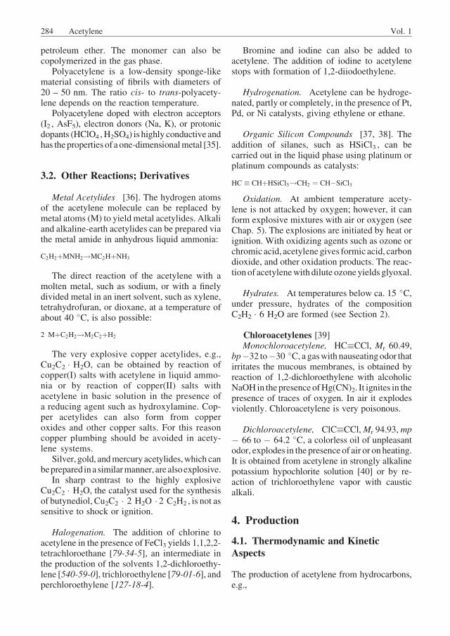
The smallest, but most important, part of apartial oxidation acetylene plant is the burner,Figure 9. Its design is nearly identical in the twoprocess variants (i.e., oil and water quench).
At the top of the burner, the preheated reac-tants, (600 �C in the case of methane) must bemixed (c) so rapidly that there are no domainswith a high oxygen concentration. Such domainscause preignition before the reactants are intro-duced into the reaction zone (g). In fact, thereaction mixture ignites after an induction timedepending on the hydrocarbon used as feed andon the preheat temperature, on the order of a fewtenths of a second. The maximum preheat tem-perature is lower for higher hydrocarbons thanfor methane. Backmixing of the gas between themixing and the reaction zones is avoided by thediffuser (e), a tube which connects the mixingzone and the burner block (f). Because of itssmooth surface and the small opening angle thereaction feed is decelerated gently and backmix-ing does not occur.
The burner block (f) consists of a water-cooled steel plate with a large number of smallchannels. The flow velocity through these chan-nels is substantially higher than the flame propa-gation speed, so that the flame below the burnerblock cannot backfire into the diffuser. The lowerside of the burner block has small openingsbetween the channels through which additionaloxygen is fed into the reaction mixture. At theseopenings small flames form and initiate the flamereaction. The strong turbulence below the burnerblock stabilizes the flame.
Under unfavorable conditions the flame mayappear above the burner block. In this case theoxygen feed must be shut off immediately andreplaced by nitrogen. This extinguishes the pre-ignition before it can cause any damage to theequipment. Such preignitions can result from amomentary shift in the oxygen : hydrocarbonratio or the entrainment of small particles ofpyrophoric iron formed from rust in thepreheaters.
As mentioned above, the hot gas leaves thereaction chamber within a few milliseconds andpasses through sprays of water or oil, which coolthe gas almost instantaneously, to about 80 �C inthe case of water or 200 – 250 �C in the case ofoil. The quench system consists of a set of nozzlesthat are fed by three annular tubes below thereaction chamber.
The concentrations of the major constituentsof the cracked gas depend on the oxygen :hydrocarbon ratio in the feed as shown in Fig-ure 10. As the oxygen supply is increased, theacetylene concentration increases until it passesthrough a smooth maximum. At the same timethere is an increase in the volume of the crackedgas. Thus maximum acetylene production isattained when a little more oxygen is used thanthe amount required for maximum acetyleneconcentration in the cracked gas. This is clearfrom the consumption of natural gas per ton ofacetylene produced and the reduction in uncon-verted methane. When the oxygen : hydrocarbonratio is too low, the reaction time is insufficientfor complete conversion of oxygen, and thecracked gas contains free oxygen. Free oxygencan be tolerated only up to a certain concentra-tion.When the oxygen : hydrocarbon ratio is toohigh, the increased velocity of flame propagationexceeds the flow velocity in the channels of theburner block, leading to preignitions.
Vol. 1 Acetylene 287
Figure 9. BASF acetylene burnerA) The burner: a) Oxygen: b) Hydrocarbon; c) Mixer; d) Concrete lining; e) Diffuser; f) Burner block; g) Reaction chamber;h) Rupture disk; i) Quench-medium inlet; j) Quench rings; k) Quench chamber; l) Manual scraper; m) Cracked-gas outlet;n) Quench-medium outlet. B) The burner block
288 Acetylene Vol. 1
Coke deposits in the reaction chamber have tobe removed from time to timewith amanual or anautomatic scraper. Normally, a burner produces25 t of acetylene per day from natural gas and30 t per day from liquid feedstocks.
Acetylene Water Quench Process (AWP),Soot Removal (Fig. 11). After quenching withwater the cracked gas leaves the burner (b) at80 – 90 �C. A certain amount of soot is formedin the reaction chamber in spite of the very shortreaction time. When natural gas is used as afeedstock, the soot is 50 kg per ton of acetylene,with LPG feedstock it is 250 kg, and with naph-tha it is 350 kg. The soot is partly removed fromthe gas by the quench, then by washing withrecirculatedwater in a cooling column (c), and bypassing the gas through an electrofilter (d). Aftercooling and soot removal, the gas has a pressureslightly above atmospheric, a temperature ofabout 30 �C, and a soot content of about1 mg/m3. The water effluents from the quenchsystem, the cooling column, and the electrofiltercarry the washed-out soot. Some gas remainsattached to the soot, causing it to float when thesoot-containing water flows slowly through ba-sin decanters (e). The upper soot layer, whichcontains 4 – 8 wt% of carbon, depending on thefeedstock, is scraped off the water surface andincinerated.
Acetylene Oil Quench Process (AOP), SootRemoval (Fig. 12). In this process the crackedgas is quenched with oil sprays and leaves theburner at 200 – 250 �C. The oil absorbs the heatfrom the gas and then passes through wasteheat boilers before returning to the quench. The
Figure 10. Burner characteristics a) Burner block; b) Reac-tion chamber; c) Flame front; d) Quench-medium inlet
Figure 11. Acetylene water quench process (AWP) a) Preheaters; b) Acetylene burner; c) Cooling column; d) Electrofilter;e) Soot decanter; f) Cooling tower
Vol. 1 Acetylene 289
sensible heat of the cracked gas represents morethan 15% of the heating value of the feedstock.The pressure of the generated steam depends onthe process configuration and can reach 15 bar(1.5 MPa).
Unlike the water quench process, where thescraped coke deposits sink to the bottom ofthe quench chamber and are easily removed, inthe oil quench the coke deposits do not settleimmediately. In order to prevent plugs in thequench nozzles a mill pump (d) is installedimmediately underneath the burner column.
The coke and soot content in the quenchcircuit is kept near 25% by sending a fractionof the coke-containing oil to externally heated,stirred kettles (coker (e)). In the kettles thevolatile matter evaporates very quickly, leadingto fluidization of the coke bed. The vapor isreturned to the burner column, while the soot isagglomerated. A fine-grained coke is withdrawnfrom the bottom of the coker.
Because of the cracking losses in the quench acertain amount of quench oil has to be addedcontinuously to the process. This makeup oil is atleast 0.15 to 0.3 t per ton of acetylene, dependingon the stability of the oil used. When residual oilfrom steam crackers is used, it can be desirable toadd up to 1 t of oil per ton of acetylene, because
the excess oil is partially converted to lightaromatic hydrocarbons.
The cracked gas leaving the quench is cooledin a burner column (c), where there are additionaloil circuits for the production of 3-bar steam andfor boiler feedwater preheat. At the top of thecolumn a small amount of a low-boiling oil(BTX ¼ benzene, toluene, and xylene) is addedto prevent deposit-forming aromatics (mainlynaphthalene) from passing downstream into oth-er parts of the plant. The cracked gas, which hasto be compressed before separation, is cooledfurther (g) by water. At this stage most of theBTX condenses and is separated from the waterin a large decanter (f).
Table 4 shows the cracked gas compositionsfor the BASF acetylene oil quench process whennatural gas, liquid petroleum gas (LPG), or naph-tha is used as feedstock. The water quench pro-cess gives very similar compositions. The rela-tive amounts of hydrogen and carbon monoxideformed depend on the hydrogen : carbon ratio ofthe feedstock used. Even when naphtha is used,almost no ethylene forms. This is because thereaction takes place above 1200 �C where theformation of ethylene is thermodynamicallyimpossible. Only a prequench with additionalnaphtha or LPG produces additional acetylene
Figure 12. Acetylene oil quench process (AOP) a) Preheaters; b) Acetylene burner; c) Burner column; d)Mill pump; e) Coker;f) Decanter; g) Final cooler
290 Acetylene Vol. 1
and ethylene at intermediate temperatures, as inthe case of two-step processes. The higherhydrocarbons require a somewhat lower reactiontemperature than methane and have a less endo-thermic heat of reaction: oxygen consumptionper ton of acetylene is lower for the higherhydrocarbons in spite of the lower preheatingtemperature.
Comparison of Oil Quench and WaterQuench Processes The advantage of the oilquench process is obvious: the heat recovery inthe form of steam makes the overall thermalefficiency in relation to primary energy inputrather high. If the thermal efficiency for theproduction of electricity is 33%, over 70% ofthe net heating value of the overall primaryenergy input is recovered in the form of productsand steam. A comparison between the oil quenchandwater quench (see Table 6) shows that the oilquench requires a net heating value input of300 – 330 GJ per ton of acetylene, of which82 GJ (27 – 25%) is lost, whereas the waterquench requires a 288 GJ input, of which 113 GJ(39%) is lost.
Acetylene Recovery Liquid acetylene is adangerous product, even at low temperatures.Separation of the cracked gas by cryogenic pro-cesses such as those used in olefin production isclearly ruled out. One exception to this rule is theacetylene recovery unit of the submerged flameprocess (Section 4.2.3) [45], in which all hydro-carbons except methane are condensed at �165C. Otherwise, acetylene is recovered by selective
absorption into a solvent. This procedure iseconomical only when the cracked gas is com-pressed. The upper limit for the pressure isdetermined by the danger of explosions, and asa rule the partial pressure of acetylene should bekept below 1.4 bar (0.14 MPa).
The solubility of acetylene in the solventsused is between 15 and 35 m3 (STP) per cubicmeter of solvent under process conditions. Thedissolved gas is recovered by depressurizing thesolvent and by vapor stripping at higher tem-peratures. All solvents used commercially,N-methylpyrrolidone (NMP), methanol, ammo-nia, and dimethylformamide (DMF), are misci-ble with water. They are recovered from the gasstreams leaving the plant by water scrubbing anddistillation.
The kinetics of acetylene formation alwayslead to the formation of higher homologues ofacetylene as byproducts [46], mainly diacety-lene, but also methylacetylene, vinylacetylene,and others. These compounds polymerize veryeasily and must be removed from the cracked gasas soon as possible. Because they are much moresoluble in the solvents than acetylene, scrubbingthe cracked gas with a small amount of solventbefore it enters the acetylene recovery stages issufficient.
Absorption Section (Fig. 13). Acetylene re-covery is illustrated here by the BASF process.N-Methylpyrrolidone is used to separate thecracked gas into three streams:
1. Higher homologues of acetylene and aro-matics, the most soluble part of the crackedgas. (This is a small stream of gas, which isdiluted with crude synthesis gas for safetyreasons and is used as fuel.)
2. Product acetylene, less soluble than the higheracetylenes, but much more soluble than theremainder of the gas
3. Crude synthesis gas (off-gas), mainly hydro-gen and carbon monoxide
In the prescrubber (b) the cracked gas isbrought into contact with a small amount ofsolvent for removal of nearly all the aromaticcompounds and C4 and higher acetylenes exceptvinylacetylene. This is done after the compres-sion of the gas if screw compressors are used butbefore compression if turbo compressors are
Table 4.BASF acetylene oil quench process, cracked gas composition
(vol%)
Component a Raw material (DH, kJ/mol)
Methane LPG Naphtha
(400) (325) (230)
H2 56.5 46.4 42.7
CH4 5.2 5.0 4.9
C2H4 0.3 0.4 0.5
C2H2 7.5 8.2 8.8
C3þb 0.5 0.6 0.7
CO 25.8 35.0 37.9
CO2 3.2 3.4 3.5
O2 0.2 0.2 0.2
Inerts balance
aDry gas, water, and aromatic compounds condensed out;bHydrocarbons with three or more carbon atoms.
Vol. 1 Acetylene 291
used because turbo compressors cannot toleratedeposits on their rotors. In the main scrubber (d)the gas is brought into contact with a muchlarger amount of N-methylpyrrolidone (NMP),which dissolves all the acetylene, the remaininghomologues, and some carbon dioxide. Crudesynthesis gas (off-gas) leaves at the top of thecolumn.
The NMP solution is degassed in several stepsin which the pressure is reduced and the temper-ature increased. The stripper (e) operates atpressures and temperatures slightly above ambi-ent. In this tower, the solution is put in contactwith a countercurrent gas stream from the subse-quent degassing step (f). This leads to the evolu-tion of carbon dioxide, the least soluble of thedissolved gases, at the top of the stripper. Thecarbon dioxide is recycled to the suction side ofthe compression and thereby is shifted into thecrude synthesis gas. The acetylene product iswithdrawn as a side stream from the stripper.The N-methylpyrrolidone solution is thencompletely degassed (f) in two further steps at110 – 120 �C, first at atmospheric, then at re-duced pressure. Vinylacetylene, methylacety-lene, and excess process water are withdrawn asbleed streams from the vacuum column (f). Thewater content of the solvent is controlled bythe reboiling rate in the vacuum column. At the
bottom of the vacuum column, degassing iscompleted, and the solvent is cooled and returnedto the main scrubber (d).
The small amount of solvent from the pre-scrubber (b) is stripped with crude synthesis gasfor recovery of the dissolved acetylene, the over-head gas being recycled to the suction side of thecompressor. The solvent is then degassedcompletely in the vacuum stripper (g), a columnwhich also accepts the bleed stream from thevacuum column (f) containing the excess processwater together with some higher acetylenes. Theoverhead vapor of the vacuum stripper containsthe higher acetylenes, water, and some NMPvapor. In a side column (h) the NMP is recoveredby scrubbing with a small amount of water,which is recycled to the main solvent stream.The gas is cooled (i) by direct contact with waterfrom a cooling circuit to condense most of thewater vapor. The higher acetylenes are dilutedwith crude synthesis gas before they enter andafter they leave the vacuum pump (j). The dilutedhigher acetylenes, which are now at a pressureslightly above atmospheric, can be used as fuelgas, e.g., for soot incineration.
In order to minimize the polymer content ofthe solvent, about 2% of the circulating flow iswithdrawn continuously from the vacuum strip-per circuit and distilled under reduced pressure,
Figure 13. BASF acetylene process — N-methylpyrrolidone absorption section a) Compressor; b) Prescrubber; c) Acetylenestripper; d)Main scrubber; e) Stripper; f)Vacuumcolumn; g)Vacuumstripper; h) Side column; i)Condenser; j)Vacuumpumps
292 Acetylene Vol. 1
leaving the polymers as a practically dry cake fordisposal.
The acetylene product from the process asdescribed above has a purity of about 98.4%, theremainder consisting mainly of propadiene,methylacetylene, and nitrogen. For most appli-cations the purity is increased to 99.7% byscrubbing with sulfuric acid and sodium hydrox-ide solutions. Table 5 compares the composi-tions of crude and purified acetylene. Table 6compares the consumption and product yieldsper ton of acetylene for the oil quench processwith those for the water quench process.
4.2.2. Other Partial Combustion Processes
Themain features of the BASF process describedin detail above are common to all partial oxida-tion processes. Therefore only the differencesbetween the BASF acetylene burner and burnersused in the Montecatini and the SBA processes[41, 47] are described. These two processes havealso attained some importance. The details of theacetylene recovery process depend on the prop-erties of the solvent, but here too the basicprinciples are the same for all processes.
Montecatini Process. The Montecatiniburner [48] has the same main components asthe BASF burner: mixing unit, gas distributor,reaction chamber, and quench. The essentialdifference is the pressure for acetylene synthesis,which can be as high as several bar. This savescompression energy, improves heat recoveryfrom the quench water, which is obtained at125 �C, and is claimed to make soot removaleasier because the cracked gas is scrubbed withwater above 100 �C. Although it is well known[7] that acetylene decomposition is accelerated
under pressure at high temperatures (> 1000 �C),the acetylene yield is comparable to that obtainedat atmospheric pressure because of the shortresidence time in the reactor. Methanol is usedat cryogenic temperatures for acetylene recov-ery. The main steps of the gas separation areabsorption of higher acetylenes and of aromatics,absorption of acetylene, stripping of coabsorbedimpurities, and desorption of acetylene.
SBA Process (of the Soci�et�e Belge del’Azote). The SBAburner [49] has the samemaincomponents as the other processes. However, ithasatelescope-like reactionchamberandadevicefor shifting the quench up and down. Thus it ispossible to adjust the length of the reaction zonefor optimum residence time at any throughput.The walls of the reaction chamber are sprayedwith demineralized water to prevent coke depos-its. This eliminates the need to scrape the reactionchamber periodically. Acetylene recovery is car-riedoutwithseveralscrubbingliquids – kerosene,aqueous ammonia, caustic soda, and liquidammonia, each with its own circuit. After soot isseparated from the gas in an electrofilter, higherhydrocarbons are absorbed in kerosene or gas oil.Carbon dioxide is scrubbed in two steps, firstwithaqueous ammonia and then with caustic sodasolution. The acetylene product is absorbed intoanhydrous ammonia and must be scrubbed withwater after desorption. All the ammonia–watermixtures are separated in a common distillationunit. This recovery scheme leads to exact separa-tion of the various cracked gas components.
Additional Remarks The Montecatini andSBA processes can also be operated with two-stage burners. A prequench with light hydrocar-bons cools the cracked gas to about 800 �C.Aftera residence time at this intermediate temperaturethe gas is cooled downwithwater. In this way theheat content of the hot gases is used for furthercracking of hydrocarbons to yield extra acetyleneand olefins. The presence of additional compo-nents in the cracked gas requires more processsteps in the gas separation units.
4.2.3. Submerged Flame Process
The submerged flame process (SFP) of BASFattracted considerable interest up to 1973 as a
Table 5. Purity of the acetylene from the BASF process
Component Crude acetylene,
vol%
Purified acetylene,
vol%
Acetylene ca. 98.42 99.70
Propadiene 0.43 0.016
Propyne 0.75 traces
Vinylacetylene 0.05 0
1,3-Butadiene 0.05 0
Pentanes 0.01 0.01
Carbon dioxide ca. 0.10 0
Nitrogen ca. 0.30 0.30
Vol. 1 Acetylene 293
partial combustion process for the production ofacetylene, ethylene, C3, and C4 hydrocarbons,and synthesis gas from feedstock of crude oil andresidues, such as Bunker C oil and vacuumresidue [44, 45]. Although it was abandoned atthe end of 1973, the need to make the mosteconomic use of raw materials has renewedinterest in this process [50].
Oxygen compressed to 16 bar (1.6 MPa)feeds a flame that is submerged in the oil. Theoil surrounding the flame is partially burnt toobtain the necessary reaction temperature andalso acts as the quenching medium. This processdiffers from the partial oxidation processes usingnatural gas and lighter hydrocarbons in five mainrespects:
1. Crude oil can be gasified without the forma-tion of residues, and the process can be oper-ated under certain conditions with heavy fueloil.
2. All the soot formed is consumed when crudeoil feedstock is used, eliminating all the pro-
blems associatedwith the storage, disposal, orutilization of acetylene soot.
3. The heat of reaction is removed by steamgeneration at 8 bar (0.8 MPa).
4. The process is operated at 9 bar (0.9 MPa) sothat the oxygen is the only compressedstream. The cracked gas is formed at a pres-sure sufficient for economic separation.
5. The design of the cracking unit is greatlysimplified because the reaction feed, fuel, andquenching medium are identical.
The process is described in detail in the liter-ature cited; therefore, only general overviews ofthe cracking unit (Fig. 14) and the separation unit(Fig. 15) are shown here. The capacities of asubmerged flame burner for acetylene and ethyl-ene are 1 t/h and 1.15 t/h, respectively. To pro-duce these quantities, 5000 m3 (STP) of oxygenand 8 – 10 t of oil are required per hour. Thecracked gas shows the following average com-position (vol%, the components grouped asstreams leaving the separation unit):
Table 6. BASF acetylene process, consumption and product yields per ton of acetylene
Consumption and product yields Oil quench Water quench
Steam (up to 15 bar) 13.0 (14.0) t ¼ 30.3 (32.6) GJ 1.5 t ¼ 3.5 GJ
Energy output 219.9 (246.5) GJ 174.9 GJ
Thermal efficiency 73.0 (74.9)% 60.8%
Energy losses, absolute per ton acetylene 81.1 (82.5) GJ 112.8 GJ
a If the natural gas contains inerts and higher hydrocarbons, the required input will remain approximately the same on a heating value basis
(LHV¼ low heating value), but the cracked gas analyses and the crude synthesis gas analyses will differ slightly.bThermal efficiency of electricity production is assumed to be 33%.
294 Acetylene Vol. 1
Main products
Acetylene 6.2
Ethylene 6.5
Crude synthesis gas
Carbon monoxide 42.0
Hydrogen 29.0
Methane 4.0
Inerts 0.6
Other hydrocarbons
Ethane 0.5
Propane 0.1
Propene 1.2
Propadiene, propyne 0.7
1,3-Butadiene 0.5
Other C4 and C5þa hydrocarbons 1.5
Remainder
Carbon dioxide 7.0
Hydrogen sulfide 0.05 – 0.5
Carbon oxide sulfide 0.03 – 0.3
aC5þ , five or more carbons
Unlike all other processes the submergedflame process uses low temperatures (–165 �C)to separate the off-gas, consisting of carbonmonoxide, hydrogen, and methane, from theC2 and higher hydrocarbons. On account of theacetylene in the condensed phase, extensivedecomposition tests have been carried out.Whereas the cracking unit (Fig. 14) and theamine scrubbing unit have been tested by Soc.Ital. Serie Acetica Sintetica, Milan, on a com-mercial scale, the remaining purification units(Fig. 15) have not. However, the experience
obtained with a pilot plant indicates that majordifficulties are not to be expected.
The submerged flame process may becomecompetitive because of its ability to use crude oiland especially residues and because of its lowlosses on the primary energy input.
Figure 14. Submerged flame process (SFP) – cracking unit a) Reactor; b) Oil cooler; c) Steam generator; d) Oil recycle pump;e) Scrubber; f) Naphtha cooler; g) Naphtha separator; h) Naphtha pump; i) Spray cooler; j) Separating vessel; k) Recycle-waterpump; l) Recycle-water cooler
Figure 15. Submerged flame process — purification unit
Vol. 1 Acetylene 295
4.2.4. PartialCombustionCarbideProcess
Calcium carbide production from lime and coalrequires a large high-temperature heat input (seeSection 4.3.4). In the thermal process some of thecoalmust be burnt to attain the necessary reactiontemperature and supply the heat of reaction. Thethermal carbide process was developed by BASF[7, 51] from1950 to 1958 to eliminate the input ofelectrical energy necessary in the classic carbideprocess. Starting in 1954, a large pilot plant, witha nominal carbide capacity of 70 t/d, was oper-ated, but in 1958 the more economical petro-chemical acetylene production halted furtherdevelopment. Carbide production is just one wayof converting coal chemically; other methodsinclude pyrolysis, hydrogenation, and gasifica-tion. The question arises as to the conditionsunder which a thermal carbide process usingoxygen can compete with the electric carbideprocess. The biggest drawback of carbide pro-duction in a shaft furnace (Fig. 16) compared tothe electric carbide process is the lack of com-mercial-scale operational experience. Specificdisadvantages are greater susceptibility to dis-ruption because of plugging of the furnace feed,more stringent specifications for the raw materi-als,more handling of solids, and the large amountof byproduct. There are two main advantages:
1. A thermal efficiency of about 50% versusabout 30% for the electrothermal process ifthe thermal efficiency of electricity produc-tion is 33%
2. Carbon monoxide production, which isdesirable because carbon monoxide can beconverted to synthesis gas by the water-gasshift reaction (! Gas Production, 3. GasTreating)
If the carbon monoxide is converted to synthesisgas and the electrical energy is produced fromfossil fuels, production costs are about one thirdlower for the thermal process than for the elec-trical process [52] based on the pilot-plant con-sumption data (Table 7).
4.3. Electrothermic Processes
Because calcium carbide is produced electrother-mally, the production of acetylene from thismaterial also is discussed in this group of pro-cesses (Section 4.3.4).
Electrothermic processes have the followingadvantages over partial oxidation:
. The energy requirement for the formation ofacetylene can be made independent of thehydrocarbons used as feedstock.
. Hydrocarbon consumption can be reducedby 50%.
. Provided that electrical energy is availableunder favorable conditions (nuclear power,hydroelectric power, cheap coal) and/or theavailability of hydrocarbons is limited,electrothermic processes are more econo-mical.
Figure 16. Partial combustion carbide process a) Carbide furnace; b) Refractory brick lining; c) Charging hopper; d) Gasoutlet; e) Oxygen jet; f) Tapping burner; g) Tapping chute; h) Bogey; i) Cyclone; j) Washing column; k) Desintegrator;l) Compressor
296 Acetylene Vol. 1
In the case of acetylene formation, the elec-tric-arc process offers optimal conditions for theendothermic reaction at high temperatures.
The development of the electric-arc processfor cracking light hydrocarbons to acetylenebegan in 1925 in Germany. The acetylene wasto be used as feedstock for butadiene production.In 1940, the first commercial plant was put onstream at Chemische Werke H€uls in Marl,
Germany. The H€uls process has since been im-proved , and the capacity raised, but it retaired theoriginal principles [53].
Feedstock for electric-arc processes may begaseous or liquid hydrocarbons or evensolids such as coal. The design of the arcfurnace and the purification section for thecracked products have to be adapted to thedifferent feedstocks. For gaseous or gasifiedhydrocarbons the classical one-step process isused: the arc burns directly in the gas beingcracked. For liquid and solid feeds, a one- ortwo-step process may be used. In the two-stepprocess hydrogen is first heated in the arc fur-nace, and then liquid or solid feed is injected intothe hydrogen plasma [54]. Figure 17 shows bothtypes of arc furnaces. Because of hydrogen for-mation during the cracking reaction, the arc burnsin a hydrogen atmosphere in both processes. Theconductivity and the high rate of ion–electronrecombination for hydrogen mean that arcsabove a certain length cannot be operated withalternating current at normal frequency and highvoltage. All commercial plants therefore run ondirect current.
Table 7. Partial combustion carbide process, consumption and
product yields per ton acetylene
Raw materials
Coke, dry (88% C) 5700 kg
Lime (92% CaO) 3140 kg
Oxygen (98%) 3560 m3 (STP) 5090 kg
Total consumption 13 930 kg
Products
Carbide (80.5%) 2850 kg= 1000 kg
acetylene
Carbon monoxide 7980 m3 (STP) 9975 kg
(CO 95.5, H2 2.0, N2 2.0, CO2
0.5 vol%)
Dust 900 kg
Losses 205 kg
Total products 13 930 kg
Figure 17. H€uls electric-arc furnaces for gaseous, liquid, and solid feed A) One-step process; B) Two-step process
Vol. 1 Acetylene 297
4.3.1. Production from Gaseous and/orGasified Hydrocarbons (H€uls Arc Process)
The plant for theH€uls arc process includes the arcfurnace section itself (Fig. 17 A), which is oper-ated at a pressure of 1.2 bar, and a low and highpressure purification system.
Arc Furnace. A cathode, a vortex chamber,and an anode make up the arc furnace. Cathodeand anode are water-jacketed tubes of carbonsteel 0.8 m and 1.5 m long, respectively,and with inner diameters of 150 and 100 mm,respectively. The arc burns between cathode andanode with a length of about 1.2 m and with acurrent of 1200 A. The cathode is connected tothe high-voltage side of the rectifier (7.1 kV)and electrically isolated from the other parts ofthe furnace. Between cathode and anode is thevortex chamber. The gas is injected into it tan-gentially at a specific velocity to stabilize the arcby creating a vortex. The arc burns in the deadzone, and the striking points of the arc on theelectrodes are forced into a rapid rotation so thatthey only burn for fractions of a millisecond atone point, which gives the electrodes a lifetimeup to 1000 h. Temperatures reach 20 000 �C inthe center of the arc. Because of the tangentialflow of the gas, the arc is surrounded by a sharplydecreasing coaxial temperature field, andthe temperatures at the wall of the electrode areonly 600 �C. Thermal losses are therefore limit-ed to less than 10% of the electrical power inputof 8.5 MW.
The residence time of the gas in the arcfurnace is a few milliseconds. In this interval,the hydrocarbons are cracked, mainly into acet-ylene, ethylene, hydrogen, and soot. At the end ofthe arc furnace, the gases are still at a temperatureof about 1800 �C. The high heat content of thisgas can be exploited for additional ethyleneproduction by means of a prequench with liquidhydrocarbons. This lowers the temperature toabout 1200 �C. Because acetylene rapidly de-composes into soot and hydrogen at these tem-peratures, the gases must be quenched immedi-ately with water to about 200 �C, i.e., a quenchrate of 106 �C/s must be achieved.
The specific energy requirement (SER) andthe acetylene yield depend on the geometry anddimensions of the furnace and electrodes, thevelocity distribution of the gas, and the kind of
hydrocarbon to be cracked. Once the furnace hasbeen designed, only the hydrocarbons can bevaried.
Process Without Prequench. Figure 18shows acetylene and ethylene yields and thespecific energy requirement (SER) of varioussaturated hydrocarbons under constant condi-tions without prequench. Methane shows thehighest SER and acetylene yield, but the lowestethylene yield. As the chain length is increased,both acetylene yield and SER decline, corre-sponding to the declining heat of acetylene for-mation from the various hydrocarbons.
Normally, pure hydrocarbons are notavailable. The results obtained from mixtures ofhydrocarbons can be expressed as a functionof the carbon number, which is the number ofmoles of carbon atoms bound in hydrocarbonsper mole of the gaseous mixture. Figure 19shows specific amounts of acetylene, ethylene,and hydrogen formed and of hydrocarbonconsumed as a function of carbon number.This function enables the H€uls process to beoptimized within certain limits, for example, forhydrogen output in relation to acetyleneproduction.
Process with Prequench. Cracking in theprequench section is essentially an ultraseveresteam cracking process. The kind and amount ofhydrocarbons used for the prequench can bevaried. Figure 20 shows the specific productyield for different prequench rates for feedingmethane to the arc furnace and propane to theprequench. Acetylene and hydrogen yields areunaffected, whereas ethylene shows a slight
Figure 18. Acetylene yield, ethylene yield, and energyconsumption for various hydrocarbons in theH€uls arc process
298 Acetylene Vol. 1
maximum and declines when the temperature isnot sufficient at a given residence time. Propeneshows a steady increase, and the C3 : C2 ratio isbelow 0.25. The relative ethylene yield fromvarious hydrocarbons is as follows: ethane100, propane 75, n-butane 72, isobutane 24,1-butene 53.
Oil Quench Because the gas temperature ofthe furnace gas after prequench is on the order of1200 �C, an oil quench system has been devel-oped to regain about 80% of the sensible heatcontent of the furnace gas as steam by heatexchange. The soot–oil mixture formed can beupgraded to a sulfur- and ash-free high-gradepetroleum coke. Figure 21 shows the H€ulssystem with oil quench.
The Purification System The process ofpurification depends on the type of the quenchsystem. In the case of water quenching, 80% ofthe carbon black is removed by cyclones as drycarbonblack, the remaining20%assoot inwater-operated spray towers. In a combined oil–waterscrubbing system, aromatic compounds are re-moved and benzene, toluene, and xylene (BTX)are recovered in a distillation process.
Figure 22 shows the principle separation andpurification steps for the furnace gas. The gasleaves the first three purification sections with acarbon black content of 3 mg/m3 and is com-pressed by four-stage reciprocating compressorsto 19 bar (1.9 MPa). The gas is washed in towerswith water in a countercurrent flow. At thebottom of the tower, the water is saturated withacetylene, whereas the overhead gas containsless than 0.05 vol% acetylene. The acetylene–water solution is decompressed in four stages.Gas from the first decompression stage returns tothe compressor to improve selectivity. The lasttwo stages operate at 0.2 and 0.05 bar (20 and5 kPa). The gas still contains about 10 vol% ofhigher acetylenes, which are removed by a cryo-genic process. The higher acetylenes are lique-fied, diluted with flux oil, stripped, and returnedto the arc furnace together with spent hydrocar-bon. A more selective solvent such as N-methyl-pyrrolidone or dimethylformamide is preferredto the water wash.
Linde and H€uls have designed an appropriatepurification system. Hydrogen and ethylene areseparated by well-known technology, such as thecryogenic process or pressure-swing adsorption(see ! Adsorption).
Process Data H€uls operates its plant with amixture of natural gas, refinery gas, and liquefiedpetroleum gas. The carbon number variesbetween one and two. Table 8 shows a typicalanalysis of feed gas and cracked gas.
Figure 19. Specific values for acetylene and hydrogenformation
Figure 20. Specific product yield for different prequenchrates
Vol. 1 Acetylene 299
The H€uls plant has 19 arc furnaces, the num-ber operated depending on the electricity supply.The arc furnaces can be started up and shut downimmediately. Two large gas holders provide astorage volume of 350 000 m3 so that the purifi-cation section operates on permanent load andthere is a dependable supply of products, even ifthe arc furnace section is operated at higher orlower load.
The plant has an annual capacity of 120 000 tacetylene, 50 000 t ethylene, 400� 106 m3
(STP) hydrogen, 54 000 t carbon black and soot,and 9600 t aromatic compounds. The energyconsumption is 1.5� 106 MW h/a.
Specific data for consumption of hydrocar-bons and energy and the production of bypro-ducts per ton of acetylene produced are asfollows:
Figure 21. Process with oil quench system a) Heat recovery; b) Arc furnace; c) Oil recovery; d) Separation of medium-boilingcompounds; e) Separation of low-boiling compounds; f) Oil regeneration
Figure 22. Principal separation and purification steps for the furnace gas of the H€uls arc process
300 Acetylene Vol. 1
Hydrocarbons to the arc furnace 1.8 t
Hydrocarbons for prequench 0.7 t
Energy for the arc furnace 9800 kW h
Energy for gas purification 2500 kW h
Ethylene 0.42 t
Hydrogen 3300 m3 (STP)
Carbon black and soot 0.45 t
Aromatics 0.08 t
Residue 0.12 t
Heating gas 0.12 t
4.3.2. Production from LiquidHydrocarbons (Plasma Arc Process)
Two different plasma furnaces, each with theappropriate reactor for the cracking of liquidhydrocarbons, were developed by Hoechst andChemische Werke H€uls in close cooperation.Both units were tested on an industrial scale ata power level of 8 – 10 MW [55]. However,neither process has actually come into use foracetylene production on account of theeconomics.
The scheme of the plasma generator used byH€uls is shown in Figure 17 B. The unit consistsof three parts: the arc furnace, the reactor, and thequench system. The arc burns over a length of1.6 m at 7 kV d.c. and 1.2 kA, resulting in apower input of 8.5 MW. It is stabilized by
hydrogen injected tangentially through the vor-tex chamber. The thermal efficiency of the fur-nace is ca. 88%of the electrical power input. Thehydrogen plasma jet passing through the anodenozzle has an energy density of 3.5 kW h/m3(STP), corresponding to an average tempera-ture of 3500 K. The liquid hydrocarbons (e.g.,crude oil) to be cracked are injected intothe cylindrical reactor to achieve good mixingwith the plasma jet and to avoid the formationof carbonaceous deposits on the wall. Withinseveral milliseconds the hydrocarbons areheated and cracked to acetylene, ethylene, hy-drogen, soot, and other byproducts before themixture is quenched with oil to 300 �C. Theacetylene ratio can be adjusted by varying theresidence time. By operation of an oil quenchwith the high-boiling residue of the crude oil,80% of the sensible heat content of the crackedgas can be recovered as steam. The soot is takenup by the quench oil and is removed from thesystem as an oil–soot dispersion having 20%soot concentration. The unconverted vaporizedfractions of the oil are condensed in oil scrubbersat a lower temperature, simultaneously cleaningthe gas of the aromatic components and fine soot.These oil fractions are recycled to the reactor andthe quench system, respectively.
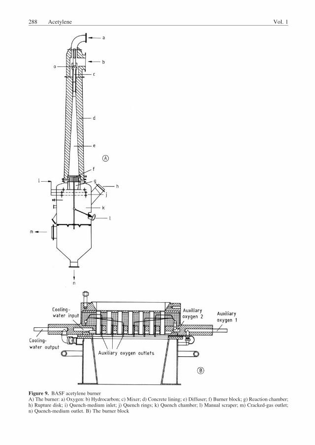
Tests were carried out with a variety of hydro-carbons from propane to naphtha, but mainlywith crude oil and residue oils. The crackingresults depend on the chemical nature of the feed.Consumption figures and yields for various feed-stocks are given in [55]. For high-boiling petro-leum fractions, the acetylene and ethylene yieldsincrease with the content of low-boiling compo-nents in the feed (see Fig. 23). Consumption andbyproduct yields per ton of acetylene for a Liby-an crude oil are summarized below:
Consumption
Crude oil consumed 3.5 t
Power (d.c.) 10500 kW h
Byproducts
Ethylene 0.46 t
Hydrogen (99.9%) 1100 m3 (STP)
Fuel gas 0.74 t
Soot – oil mixture (20% soot) 1.2 t
Hoechst used a high-intensity three-phase a.c. arcfurnace at 1.4 kV and 4.2 kA, giving a powerinput of 10 MW [55]. The thermal efficiencywas
Table 8. Typical analysis of feed and cracked gas
Feed gas,
vol%
Cracked gas,
vol%
C2H2 0.4 15.5
C3H4 1.4 0.4
C4H2 1.2 0.3
C4H4 1.7 0.4
C2H4 0.8 6.9
C3H6 3.6 1.0
Allene 0.4 0.2
C4H8 1.0 0.2
C4H6 0.9 0.2
C5H6 0.6 0.2
C6H6 0.5 0.5
CH4 64.6 13.8
C2H6 7.5 0.4
C3H8 3.6 0.3
C4H10 4.6 1.0
C5H12 0.5 0.1
H2 4.5 57.6
CO 0.5 0.6
O2 0.1 0.0
N2 1.6 0.4
Vol. 1 Acetylene 301
90%. Because of the high amperage the graphiteelectrodes had to be replenished continually. Thegenerator was lined with graphite. Differentreactor designs for ethylene: acetylene ratios of0.5 and 1.0 were developed by varying the mix-ing intensity of the hydrogen plasma jet with theliquid hydrocarbon. The tests were carried outwith naphtha feed (see Table 9). The cracked gaswas quenched with residue oil, in a mannersimilar to that described in the H€uls process.
The acetylene concentration in the H€uls pro-cess and the Hoechst process was ca. 14 vol% sothat in principle the same acetylene separationprocess can be used as described above for the arcprocess.
4.3.3. Production from Coal (Arc CoalProcess)
Numerous laboratory tests for the conversion ofcoal to acetylene using the arc or plasma pro-
cesses have been carried out since the early1960s [56]. The results can be summarized asfollows:
. Acetylene yields up to 30% can be obtained.
. Because of the rapid heating of the coal in theplasma jet, a higher total gas yield can beachieved than is indicated by the volatiles ofthe coal measured under standard conditions.
. Hydrogen (instead of argon) plasma gas con-siderably increases the acetylene yield.
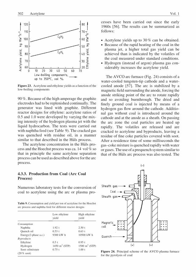
The AVCO arc furnace (Fig. 24) consists of awater-cooled tungsten-tip cathode and a water-cooled anode [57]. The arc is stabilized by amagnetic field surrounding the anode, forcing theanode striking point of the arc to rotate rapidlyand so avoiding burnthrough. The dried andfinely ground coal is injected by means of ahydrogen gas flow around the cathode. Additio-nal gas without coal is introduced around thecathode and at the anode as a sheath. On passingthe arc zone the coal particles are heated uprapidly. The volatiles are released and arecracked to acetylene and byproducts, leaving aresidue of fine coke particles covered with soot.After a residence time of some milliseconds thegas–cokemixture is quenched rapidly with wateror gases. The use of a prequench system similar tothat of the H€uls arc process was also tested. The
Figure 23. Acetylene and ethylene yields as a function of thelow-boiling components
Table 9. Consumption and yield per ton of acetylene for the Hoechst
arc process and naphtha feed for different reactor designs
Low ethylene
yield
High ethylene
yield
Consumption
Naphtha 1.92 t 2.50 t
Quench oil 0.53 t 0.63 t
Energy(2-phase a.c.) 9300 kW h 10500 kW h
Byproducts
Ethylene 0.5 t 0.95 t
Hydrogen 1450 m3 (STP) 1500 m3 (STP)
Soot–oilmixture
(20% soot)
0.75 t 1.00 tFigure 24. Principal scheme of the AVCO plasma furnacefor the pyrolysis of coal
302 Acetylene Vol. 1
system pressure can be varied between 0.2 and1.0 bar (20 and 100 kPa).
H€uls’ pilot plant uses the same plasma furnaceas for the crude oil cracking, but with 500 kW ofpower [58]. The dried and ground coal is injectedinto the plasma jet, and the coal is cracked toacetylene and byproducts in the reactor. Thereactor effluent can be prequenched with hydro-carbons for ethylene production or is directlyquenched with water or oil. Char and higherboiling components are separated by cyclonesand scrubbers, respectively. The problem in thereactor design is to achieve thorough and rapidmixing of the coal with the plasma jet and toavoid forming carbonaceous deposits on thewall. Smaller amounts of deposits can be re-moved by periodic wash cycles with water.Operation times of 2.5 h by AVCO and 5 h byH€uls have been reported.
Experiments published by H€uls and AVCOshow that at the optimal residence time theenergy density of the plasma jet, the specificpower, and the pressure all greatly affect theacetylene yield (Fig. 25 and Fig. 26). Other para-meters affecting the yield are the amounts ofvolatiles in the coal and the particle size. Thelowest figures for the specific energy consump-tion published by AVCO are of the order of27 – 37% based on water-free coal.
In addition to acetylene, the exit gas containsconsiderable amounts of CO, depending on the
oxygen content of the coal. Because nitrogen andsulfur are present in the coal, other byproductsare HCN, CS2, COS, and mercaptans. The gasseparation system is therefore designed accord-ingly [59]. Depending on the hydrogen content ofthe coal, the process is either self-sufficient inhydrogen or has a slight surplus. The total gasyield of the coal based on a volatile content in thecoal of 33% is up to 50%. Thus 50% of the coalremains as char. Tests with a view to using thischar in the rubber industry have been unsuccess-ful so far. Thus the char can be used only forgasification or as a fuel.
In all the processes under development, theproduction of ethylene from coal requires severalprocess steps (Fig. 27), resulting in a high capitaldemand for a production plant. In contrast, theacetylene production from coal arc pyrolysis isstraightforward, leading to lower investmentcosts. Demonstration units on a higher powerlevel are therefore scheduled by both AVCO andH€uls.
4.3.4. Production from Calcium Carbide
At present, the generation of acetylene fromcalcium carbide (! Calcium Carbide) is ofprimary importance for welding and for theproduction of carbon for batteries. The particularraw-material situation and the use of specialprocesses are two common reasons for continu-
Figure 25. Effect of the energy density of the plasma on thecracking of coal (AVCO)
Figure 26. Acetylene yield and specific energy requirementas a function of pressure (H€uls)
Vol. 1 Acetylene 303
ing to use acetylene generated from carbide in thechemical industry.
The reaction of calcium carbide and water toform acetylene and calcium hydroxide is highlyexothermic:
CaC2þ2 H2O!C2H2þCaðOHÞ2 D H ¼ �129 kJ=mol
The acetylene generator used for commercialproduction must therefore be designed to allowdissipation of the heat of reaction. In the event ofinadequate heat dissipation, for example, whengasification proceeds with insufficient water, thecarbide may become red-hot. Under certain cir-cumstances (including increasing pressure), thismay cause the thermodynamically unstable acet-ylene to decompose into carbon and hydrogen.(For safety precautions see Chap. 5.) Carbide forthe production of acetylene is used in the follow-ing grain sizes (mm): 2 – 4, 4 – 7, 7 – 15,15 – 25, 25 – 50, 50 – 80. This classification isvirtually identical in most countries: DIN 53922(Germany); BS 642:1965 (United Kingdom); JIS
K 1901 – 1978 (Japan); Federal Specification0�6–101 b/GEN CHG NOT 3 (United States).In addition, grain size 0 – 3 is used for the drygeneration of acetylene.
Pure calcium carbide has a yield number of372.66. This means that the gasification of 1 kgof carbide yields 372.66 L acetylene at 15 �C and1013 mbar (101.3 kPa). Commercially availablecarbide has a yield number of 260 – 300.
A distinction is made between two groups ofacetylene generators (with continuous rates ofproduction greater than 10 m3 acetylene perhour): the wet type and the dry type.
In wet generators, the acetylene is convertedwith a large water excess. In most cases, alime slurry containing 10 – 20 wt% calciumhydroxide is obtained. The heat of reactionincreases the temperature of the generator waterand is removed from the reactor with the limeslurry.
In dry generators, the water mixed with thecarbide is just sufficient for chemical reactionand for dissipating the heat of reaction. Thecalcium hydroxide is obtained in the form of a
Figure 27. Alternative routes from coal to ethylene and acetylene
304 Acetylene Vol. 1
dry, easily pourable powder having a residualmoisture content of 1 – 6%. The heat of reactionis dissipated by evaporation of part of the gener-ator water.
Generators are classified according to theirworking pressure as either low or medium pres-sure. This classification is governed by the reg-ulations concerning acetylene plants and calciumcarbide storage facilities (Acetylenverordnung)[60] issued by Deutscher Acetylenausschuß(German acetylene committee) and the associat-ed technical rules for acetylene plants andcalcium carbide storage facilities TRAC (Tech-nische Regeln f€ur Acetylenanlagen undCalcium-carbidlager) [61]. The Acetylenverordnung andTRAC constitute a comprehensive set of rules forhandling acetylene. Recommendations in othercountries (e.g., United States) deal only withsome aspects, such as safety precautions [62].
Low-pressure generators are designed for amaximum allowable working pressure of0.2 bar. They must be rated for an internal pres-sure of at least 1 bar. Lower pressure ratings arepossible if proof is given in each particular casethat the generator can withstand the expectedstress (maximumworking pressure, water filling,agitator, etc.; TRAC 201).
Medium-pressure generators have a maxi-mum allowable working pressure of 1.5 bar.They must be rated for an internal pressure of24 bar. A design pressure of 5 bar suffices when-ever the generators are equipped with rupturedisks of a defined size and specified responsepressure (3 – 4.5 bar, TRAC 201).
4.3.4.1. Wet Generators
Wet generators are used primarily for the pro-duction of small amounts of acetylene, e.g., forwelding purposes. Wet generators work by oneof three different principles [63]:
1. The carbide-to-water principle, where thecarbide is mixed with a large excess of waterat a rate corresponding to the gas withdrawalrate. Most generators work by this principle.
2. The water-to-carbide principle (drawer typegenerators), where water is added at a con-trolled rate to the carbide, which is held in areplaceable container (drawer).
3. The contact principle (basket generators),where the carbide, which is held in a basket,
is immersed into the generator water. Thistype is designed so that the water drifts off thebasket as a result of the gas pressure at low gaswithdrawal rates and, conversely, returns tothe basket when gas withdrawal ratesincrease.
Medium-Pressure Generators The MesserGriesheimMF 1009 is a typical carbide-to-watergenerator (Fig. 28).
The carbide skip (a) is filled with carbideof the 4 – 7 grain size. The skip is connected bygas-tight gates to the hopper (b) and is purgedof air by nitrogen or acetylene. The carbidedrops into the hopper (b) and is fed continuouslyby the feeding system (c) to the gasificationchamber (d). The gasification chamber containswater up to a level defined by the generatorcapacity and is equipped with an agitator (e) forwhirling the lime slurry. The heat evolved ingasification heats the generator water. For con-tinuous operation the water temperature must notexceed 90 �C; therefore, fresh water is admittedcontinuously to the gasification chamber. If thedefined water level is exceeded, the slurry valve(f), controlled by a float, opens, allowing theexcess water and the lime slurry to be dischargedfrom the generator.
The acetylene generated collects above thewater and is withdrawn. The feeding system
(c) is controlledby thegas pressure, i.e., the rate atwhich carbide drops into thegasification chambervaries directly with the rate of gas withdrawal.
The carbide stock in the hopper (b) is suffi-cient for about one hour, but the skip (a) can berefilled with carbide and replaced on the hopperso that continuous operation is possible. The wetgenerator described has a continuous hourlyoutput of 75 m3 of acetylene. The skip holds1000 kg of carbide.
Low-Pressure Generators. The workingprinciple of the low-pressure carbide-to-watergenerators is very similar to that of the medi-um-pressure carbide-to-water generator de-scribed above. In most cases, a downstreamacetylene holder, normally of the floating gasbell type, is provided. In contrast to the medium-pressure generator, in which the carbide feed rateis controlled by the acetylene gas pressure, thefeed rate in the low-pressure generator is con-trolled by the position of the bell in the acetyleneholder, i.e., by the gas quantity.
Products. The acetylene generated in thewet generator can be used for welding, oftenwithout further purification. In certain cases,coke- or gravel-filled purifiers or a wet scrubberare connected downstream from the generator forseparating solid or liquid particles. Before it isfed to a synthesis unit, the acetylene must bepurified chemically (see Section 4.3.4.3).
The lime slurry formed is fed into pits. Here,the calcium hydroxide settles in the form of alime dough containing 35 – 75 wt% water (wetlime, carbide lime dough). This dough is used ascarbide lime.
4.3.4.2. Dry Generators
Dry generators are mainly used for the produc-tion of large quantities of acetylene for chemicalsynthesis.
Compared to the wet generator, the primaryadvantage of the dry generator is that the drycalcium hydroxide formed as a byproduct can beused in other processes more easily, more cheap-ly, and in a more diversified way than the limeslurry obtained in the wet generator [64]. More-over, lime recycling into the carbide productionprocess is only possible with dry calciumhydroxide.
A high gasification rate and the elimination ofthe risk of overheating were originally the mostimportant criteria for the design of dry genera-tors. Early designs of dry generators worked bycontinuous renewal of the reaction surfaces ofcoarse carbide with the aid of rotating drums,blades, vibrating screens, and similar equipment.
Typical examples are the early generator ofShawiniganChemicals [65] and the Piesteritz drygenerator [66].
Although a number of factors affect the gasi-fication rate of carbide, e.g., density, porosity,and crystalline structure, above all it is the spe-cific surface that affects the carbide gasificationrate the most. Hence, dry generators work withfinely ground carbide (0 – 3 mm), which gasifiesin a fraction of the time needed for coarse car-bide. The result is a high space–time yield.
A typical application of this principle is thelarge-scale Knapsack dry generator, which wasdeveloped at the Knapsack works of Hoechst.This type of generator is used worldwide and isdescribed in more detail below (Fig. 29).
Carbide of the grain size 0 – 3 falls from thechain conveyor (a) into the subdivided feed bin(b). The chain conveyor is loaded with material
Figure 29. Knapsack dry generator a) Chain conveyor;b) Feed bin; c) Star wheel; d) Carbide feed screw; e) Genera-tor; f) Lime lockhopper; g) Lime discharge screw; h) Limescraper; i) First scrubbing tower; k) Second scrubbing tower;l) Dip seal
306 Acetylene Vol. 1
from the carbide bin. Because of the recirculatingstream of carbide the feed bin (b) is full at alltimes. The carbide layer in the feed bin (b) acts asa gas seal between the generator and the carbideconveying system.
The carbide is fed to the generator (e) via thestar wheel (c) and the carbide feed screw (d). Thelargest generator of this kind built to date has adiameter of 3.5 m and an overall height of ap-proximately 8.0 m. The generator has up to 13circular trays. These are so designed as to leavealternate annular gaps on the shell side and at thecentral agitator shaft. The agitator shaft movesstirrer paddles across the trays.
The carbide first reaches the uppermost traywhere the generator water is also admitted. Thereactionmixture consisting of carbide,water, andcalcium hydroxide is pushed by the stirrer pad-dles towards the outer edge, drops on to thesecond tray, returns towards the center, etc.When it reaches the last tray, the carbide hasbeen fully gasified. The calcium hydroxide,which still contains up to 6% water, drops intothe lime lockhopper (f). Here, a lime layer twometers deep serves as the gas closure betweengenerator and lime conveying system.The lime iswithdrawn continuously.
The gas leaving the generator through the limescraper consists of 25% acetylene and ca. 75%water vapor. The water vapor is the result ofdissipating themajor portion of the reaction heat.Depending on the generator load, up to severalhundred kilograms of lime hydrate dust are car-ried along with the acetylene. The lime scraper(h) retains the major portion of this dust andreturns it to the generator. The remainder is senttogether with the gas into the first scrubbingtower (i). Here, lime slurry is sprayed into thehot acetylene gas (ca. 90 �C) to scrub out the limedust; part of the water vapor condenses becauseof the simultaneous cooling. In the second scrub-bing tower (k), the acetylene is sprayed withatomized water to cool the gas below 40 �C;additional water vapor condenses here. Anyammonia still present in the gas is also removed.
The acetylene leaves the generator via the dipseal (l). It still contains certain impurities in theform of sulfur and phosphorus compounds.
The Knapsack dry generator is suitable for acarbide throughput of 15 t/h, corresponding to anacetylene quantity of 3750 m3/h. During thisprocess, about 17.5 t of calcium hydroxide per
hour are obtained. The pressure in this low-pressure generator amounts to approximately1.15 bar (115 kPa).
The dry generator of Shawinigan Chemicals,Montreal [67], also processes finely ground car-bide and has a variety of applications. It consistsof several superimposed troughs. Carbide andwater are fed into the uppermost trough. Thereacting mixture, which is constantly kept inmotion by blades, flows over a weir onto thetrough below, etc. At the uppermost trough,water is admitted at such a rate that carbide-freecalcium hydroxide can be withdrawn at the low-ermost trough. The generated acetylene is puri-fied in two scrubbing towers and cooled.
The calcium hydroxide formed (carbide lime)has a wide range of applications, e.g., in thebuilding industry (for preparing mortar, cement,etc.), in the chemical industry (for neutralizationand for recycling to the carbide furnace), inagriculture (as fertilizer), and for water purifica-tion and waste water treatment [64].
4.3.4.3. Acetylene Purification
During the gasification of carbide with water,gaseous compounds become mixed with theacetylene, and these must be removed becausethey have a harmful effect on the downstreamchemical synthesis processes. The impurities aremainly sulfur and phosphorus compounds. Theycan be removed by one of the following purifi-cation processes.
In the first process, dilute chlorinated water isused as the oxidizing agent. The chlorine con-centration of the water is limited to 1.5 g/L toprevent the formation of unstable chlorine com-pounds, which present an explosion hazard. Thechlorine scrubbing step is followed by a causticsoda scrubber to remove the hydrogen chlorideformed during the oxidation process. The disad-vantage of this purification process is that con-siderable quantities of scrubbing water areproduced.
The second process uses 98% sulfuric acid asthe oxidizing agent [68]. Because very smallquantities of sulfuric acid are admitted, it isdifficult to dissipate the heats of absorptionand reaction. Heating the acetylene results inincreased formation and settling of polymeriza-tion products in the purification stage. Forthis reason the gas requires additional cooling
Vol. 1 Acetylene 307
in the event that the acetylene contains appreci-able quantities of impurities. Moreover, it isrecommended that a second scrubbing tower bekept on standby if a high onstream factor isdesired (e.g., 91% = 8000 h/a operating time).
The sulfuric acid scrubber is followed by acaustic soda scrubber, in which the sulfur dioxideformed during oxidation is removed.
The main advantage of this purification meth-od is that virtually no waste water is obtained.The small amount of polluted, highly concentrat-ed sulfuric acid can be used, for example, infertilizer plants.
These two purification processes yield thefollowing acetylene purities (by volume):
Acetylene > 99.5%
Sulfur, as H2S < 10 ppm
Phosphorus, as H3P < 10 ppm
As a result of the extremely good sorptionproperties of the concentrated sulfuric acid, verypure acetylene can be expected.
4.4. Other Cracking Processes
4.4.1. ThermalCrackingByHeatCarriers
Well-known processes using heat carriers, suchas the Wulff and Hoechst high-temperaturepyrolysis (HTP) processes, are no longer usedbecause they require refined petrochemical feed-stocks such as naphtha and liquid petroleum gas.TheWulff process uses refractory material as theheat carrier, whereas the Hoechst HTP processuses hot combustion gases.
Newer processes, which are able to convertcrude and heavy distillates into olefins and con-siderable amounts of acetylene, are still in thepilot-plant stage. These processes include theadvanced cracking reactor process developed byKureha, Chiyoda, and Union Carbide, usinghigh-temperature superheated steam, and Dow’spartial combustion cracking process, using hotcombustion gases produced from oxygen andfuel oil as the heat carrier.
Wulff Process [69, 70, p. 58]. This processis based on indirect heat transfer, an approachfundamentally different from the partial-oxida-tion and electric-arc processes. The hydrocarbonfeed is cracked in refractory ovens previously
heated by combustion gas. After cracking, theproducts are quenched outside the reactor. Sootformation is a serious problem because the feedcannot be heated as rapidly as in the partial-oxidation or arc processes. This problem can bediminished by using a feed with a higher hydro-gen:carbon ratio. However, methane is not suit-able because of the high temperature and highheat of reaction required, resulting in a lowconversion rate. Thus the best feed for the Wulffprocess is ethane or propane.
Hoechst High-Temperature Pyrolysis(HTP) Process (Fig. 30) [1, 70, p. 55, 71].This is a two-stage process. In the first stage,heat is produced in the burner by the combustionof residual cracked gas from the acetylene recov-ery section (CO, H2, CH4) with oxygen. Imme-diately after combustion, the temperature isabout 2700 �C; this is moderated to about2300 �C by the injection of steam before thereactor is entered. In the second stage, the feed-stock naphtha is injected, and the adiabatic crack-ing reaction takes place. A final temperature ofabout 1300 �C is reached: This determines the
Figure 30. High-temperature pyrolysis (HTP) process
308 Acetylene Vol. 1
cracked gas composition. By varying the feedrate of naphtha the acetylene–ethylene ratio canbe altered from 30 : 70 to 70 : 30. However,thermodynamic and economic considerationsshow that the optimum ratio is 40 : 60.
After a reaction time of a fewmilliseconds thecracked gas is quenched to approximately 250 �Cby the injection of cracked oil from the process.The oil absorbs heat from the cracked gas and ispassed through waste heat boilers, raising thesteam pressure. No soot is formed in this process,evenwhen crude oil is used as feed because of thehigh steam content of the carrier gas.
After the oil crisis of 1973 the process becameuneconomical in spite of its high thermal effi-ciency, and in 1976 it was shut down after 15years of operation. However, one unit is stillrunning in Czechoslovakia.
Kureha, Chiyoda, Union Carbide Ad-vanced Cracking Reactor (ACR) Process[72]. To avoid dependence on oil refineries orgas processors for the supply of feedstocks,processes for directly cracking crude oil havebeen developed by various companies for theproduction of olefins. Some of these processesoperate at reaction temperatures intermediatebetween those of the usual crack processes forolefins and those for acetylene. The ACR process(Fig. 31) uses a multi-port burner to produce a
heat carrier gas of 2000 �C by the combustion ofH2 – CH4 mixtures with oxygen in the presenceof steam preheated to 800 �C.
The oil to be cracked is introduced throughnozzles into the stream of carrier gas and passesinto an advanced cracking reactor, where the reac-tion takes place adiabatically at 5 bar (0.5 MPa).The initial temperature is 1600 �C; the final tem-perature at the exit of the reactor is 700 – 900 �Cafter a residence time of 10 – 30 ms. The crackedgas is quenched by oil in an Ozaki quench cooler(Fig. 32), where steam production up to 120 bar(12 MPa) is possible. This particular boiler designwas developed for a high heat transfer ratewithoutcoke formation on the exchanger surfaces. Yieldsreported for Arabian light crude oil are 11.2 wt%hydrogen and methane, 40.7 wt% olefins, and4.2 wt% acetylene. The acetylene yield is aboutten times higher than in usual olefin processes.
Dow Partial Combustion Cracking (PCC)Process [72]. The basic idea of this process is toreduce coking and soot formation considerablywhen heavy feeds are cracked and when hydro-gen is present in the reaction mixture. The PCCprocess (Fig. 33), which accepts crude oil andheavy residue as feedstock, attains a high partialpressure of hydrogen in the reaction zone byrecycling the quench oil (produced in the pro-cess) to the burnerwhere it is partially oxidized to
Figure 31. Advanced cracking reactor process (ACR) a) Crude distillation column; b) Burner; c) Advanced cracking reactor;d) Ozaki quench cooler; e) Oil gasoline fractionator; f) Compressor; g) Acid gas removal column; h) Gas separator
Vol. 1 Acetylene 309
yield synthesis gas. Thus there is no need to find ause for the quench oil as in the case of the ACRprocess. Starting from residual oil boiling above343 �C, yields are given as 12.4 wt% methane,about 38 wt% alkenes, and 2.5 wt% acetylene.This is seven to eight times more acetylene thanthat obtained from a steam cracker, but less thanthe acetylene yield of the ACR process, becauseof a residence time in the reaction zone which isthree to ten times longer.
4.4.2. Acetylene as a Byproduct of SteamCracking
In a steam cracker saturated hydrocarbons areconverted to olefinic products such as ethyleneand propene. Besides these desired components,acetylene and many other products are formed inthe cracking process (Fig. 36). The concentra-tion of acetylene depends on the type of feed, theresidence time, and temperature (cracking sever-ity: expressed as conversion or propene/ethyleneratio P/E). Typical data are given in Table 10.The acetylene concentration in the off-gas fromthe furnace varies between 0.25 and 1.35 wt%.In certain cases of propane and butane crackingthe the raw gas can contain up to 2.1 wt%acetylene with corresponding very low amountsof propyne and propadiene. The correspondingcontent of acetylene in the C2 fraction is about0.4 – 2.5 wt%. An ethylene plant producing400 000 t/a ethylene produces 4500 –11 000 t/a acetylene. The acetylene is removedby catalytic selective hydrogenation or solventextraction. Today the dominating acetyleneremoval process is selective hydrogenation.
Acetylene Hydrogenation Most ethyleneplants are equipped with a hydrogenation unit.Acetylene is converted selectively toethyleneonaPd-doped catalyst. Whereas in the past mainly Nicatalysts were used, today Pd catalysts are dopedwith other metals such as silver to improve selec-tivity [73]. Typical process conditions are tem-peratures of about 40 – 120 �C, pressures of 15 –40 bar and space velocities of 1000 – 120 000 kgL�1 h�1. Depending on the type of feed and theplant, there are several process options:
2. Raw-gas hydrogenation (hydrogenationbefore C2/C3 separation, stream containingH2, CO and all hydrocarbons of the raw gasafter cracked gas compression).This variantof front-end hydrogenation is only used in gascrackers where the content of C3þ hydrocar-bons is comparable low.
3. Tail-end hydrogenation (pure C2 stream con-taining C2H2, C2H4, and C2H6; separate ad-dition of an equimolar amount of hydrogen isnecessary)
Figure 32. Ozaki quench cooler
Figure 33. Dow partial combustion cracking process (PCC)a) Reactor; b) Quench boiler; c) Quench column; d) Stripper;e) Decanter
310 Acetylene Vol. 1
Typical specifications for acetylene content inthe ethylene product are< 2 ppm with a tenden-cy to further reduction to < 1 ppm.
General aspects of the process and the catalystrequirements are reviewed in [74–76] (see also! Ethylene, Section 5.3.2.2.).
Acetylene Recovery Acetylene is extractedfrom the C2 fraction of the steam cracker. Thesolvent must fulfil the following criteria:
. Melting point lower than the dew point of thefeed gas
. High solubility of acetylene at a temperaturenear the dew point of the C2 fraction
. High acetylene selectivity ([9, 11])
. High chemical and thermal stability
. No foaming tendency due to traces ofhydrocarbons
. Low toxicity
. Low vapor pressure at the operatingtemperature
After testing many solvents, including DMF,NMP, and acetone, the most suitable solvent forsuch a process proved to be DMF. The solubilityof acetylene as a function of temperature isshown in Figure 5.
The process for the recovery of high-purityacetylene is shown in Figure 34 [77]. The gas-eous C2 mixture, consisting of ethylene, ethane,and acetylene, is fed to the acetylene absorber;the gas stream is contacted with counterflowinglean DMF at a pressure of 0.8 – 3.0 MPa. Theprocess is suitable for the full pressure rangeprevailing in any of the known ethylene process-es. The entire acetylene and some of the ethyleneand ethane are dissolved by the solvent. Waterand carbon monoxide decrease the solubility ofacetylene. Furthermore, water causes hydrolysisof DMF, resulting in additional formation ofcarbon monoxide. Entrainment of DMF at thetop of the column is avoided by a reflux stream.The purified C2 fraction, containing < 1 ppm ofacetylene, is fed to the C2 splitter. The rich
Table 10. Yields of unsaturated components (wt%) in raw gas from steam cracking
solvent stream is sent to the ethylene stripper,which operates slightly above atmospheric pres-sure. Ethylene and ethane are stripped off andrecycled to the first stage of the cracked gascompression. Any acetylene entrained with theoverhead gas is recovered by washing with coldsolvent at the top of the stripper. In the acetylenestripper, pure acetylene is isolated from the top ofthe column. After cooling and heat recovery, theacetylene-free solvent is recycled to the absorberand ethylene stripper. The acetylene product hasa purity of > 99.8% and a DMF content of lessthan 50 ppm and is available at 10 kPa andambient temperature.
The material balance and the utilities con-sumption of an acetylene recovery unit are listedin Tables 11 and 12. At present, more than112 000 t/a of petrochemical acetylene fromtwelve olefin plants worldwide is recovered bythis technology. With a big drop in the totalacetylene market in 2001, the market decreasedon average by 6.8% per year from 1998 to 2003,and only a marginal growth rate is expected until2009 (max. 2% per year) [134]. For this reasonduring the last five years (2006) no new acetylenerecovery facilities have been erected. Only someexisting plants were expanded. In North Amer-ica, for example, there are currently only twomajor companies producing acetylene as byprod-
uct of ethylene production, i.e., DowChemical inTaft, LA, and Petroment at Varennes in Canada[135]. Figure 35 shows an industrial plant with adesign capacity of 14 400 t/a of high-purityacetylene.
A material balance for ethylene plant outputsincluding acetylene extraction or hydrogenationis shown in Figure 36 [79]. The economic eval-uation shows that petrochemical acetylene re-mains attractive even if the price of ethylene isdoubled. It is economical to retrofit acetyleneabsorption in an existing olefin plant equippedwith a catalytic hydrogenation. Isolation of acet-ylene obtained as an unavoidable byproduct ofethylene production is the economically mostattractive route to cover acetylene demand.
A similar process is available for propyne (see! Propyne)
5. Safety Precautions,Transportation, and Storage
General literature is given in [10, 80, 81].
5.1. General Safety Factors and SafetyMeasures
Decomposition and Combustion. Acety-lene is thermodynamically unstable under nor-mal conditions. Decomposition into carbon andhydrogen can achieve temperatures of about3100 �C, but due to formation of other products,the temperature reached adiabatically is 2800 –2900 �C. The decomposition can be initiated byheat of reaction, by contact with a hot body, byan electrostatic spark, by compression heating, orby a shock wave. The decomposition induced byheating the wall of the container or pipe is very
Table 11. Material balance (mol%) for an acetylene recovery process operating on the C2 fraction from a plant producing 400 000 t/a C2H4
(Linde) [78]
Gas to absorber Purified gas Recycle gas Product C2H2
Methane trace trace
Acetylene 2 1 ppm 4 99.8
Ethylene 82 83.5 85.7 0.2
Ethane 16 16.5 10 trace
C3 trace trace 0.3 trace
DMF 1 ppm trace trace
Temperature, K 252 249 255 258
Pressure, MPa 2 1.98 0.11 0.12
Flow rate, kmol/h 2186 2126 17.5 52.5
Table 12. Consumption of utilities for an acetylene recovery process
operating on the C2 fraction from a plant producing 400 000 t/a C2H4
(Linde) [78]
DMF, kg/h 1.3
Heating steam, t/h 3.9
Cooling water, m3/h 100
Electrical energy, kW 125
Refrigerant, GJ/h 6.3
Quench water, GJ/h 3.1
Plot area, m�m 15� 40
312 Acetylene Vol. 1
sensitive to the pressure, the size and shape of thecontainer or the diameter of the pipe, the materialof the container, and traces of impurities or othercomponents. Solid particles such as rust, char-coal, alumina, and silica can lower the ignitiontemperature compared to clean steel pipe.
Decomposition gives rise to differentscenarios:
. Working range I (deflagration): a flame pro-duced by decomposition or combustion andpropagates at a velocity below the velocity ofsound into the unconverted gas (pressure rises
simultaneously in front of and behind the flamefront)
. Working range III (detonation): the flame pro-pagates at ultrasonic velocity into the uncon-verted gas (shock wave between low pressurein the unconverted gas and high pressure in theconverted gas)
. Working range II (intermediate between I andIII): often the propagation velocity of a def-lagration is not constant (it increases withincreasing density, temperature, and turbu-lence), and therefore a change from deflagra-tion to detonation is observed
As consequence, design criteria for piping andother components are proposed for the differentworking ranges and depend on the diameter of thepipe. Limit lines for deflagration and detonationare given in [82] on the basis of the work ofSARGENT [83]. An extended Sargent diagram isshown in Figure 37.
The limits are influenced by the method ofignition (e.g., melting wire or a detonator cap).Changing the method of ignition from a meltingPt wire (Reppe) to the exploding wire ignitor(ignition energy ca. 70 J) used by BAM resultedin lower stability pressures for acetylene mix-tures [84] and pure acetylene [85] (Table 13). Adescription of the experimental setup can befound in [133].
Mixtures of acetylene with methane havehigher stability pressures than those with nitro-gen or hydrogen. The phlegmatizing influence offoreign gases increases in the order H2 < N2 <CO2 < NH3, which corresponds to the heatcapacities of these gases [133]. For C2H2 –C2H4 mixtures the stability pressure rises withincreasing ethylene fraction. However, a signifi-cant effect can be observed only at C2H2 contents
Figure 36. Material balances of a 300 000 t/a ethylene plant equippedwith eitherC2 hydrogenation or acetylene extraction (allrates in kg/h, the numbers in parentheses are for the solvent extraction process) [79] * Chemical grade
Figure 37. Detonability limits of acetylene [83, 88]A) Deflagration limit; B) Detonation limitDetonation limits: a) Thermal ignition in a plain pipe(a1 melting wire, 20 – 80 J; a2 detonator cup, �2400 J);b) Thermal ignition plus orifice; c) Ignition by chemicalreaction in a shock wave; d) Range of possible quasi-detona-tion depending on ignition energy of shock wave; x) andy) Limiting ignition pressure for thermal ignition with melt-ing Pt wire and with detonator cup, respectively
Table 13. Stability pressure (bar) of acetylene and acetylene mixtures
for two methods of ignition and pressure increase [84, 85]
Mixture Ignition method pex/paa
Reppe BAM (BAM)
100% C2H2 1.4 0.8
90% C2H2/10% N2 1.8 1.0 8.6
90% C2H2/10% CH4 2.1 1.0 7.2
90% C2H2/10% H2 1.6 0.9 6.9
50% C2H2/50% N2 9.0 3.6 6.3
50% C2H2/50% CH4 14.7 12.9
50% C2H2/50% H2 4.7 2.5 5.5
apex/pa: ratio of maximum pressure to pressure before ignition.
314 Acetylene Vol. 1
< 50% [133]. Further information on the effectof additional gases on acetylene decompositionis given in [86]. The dependence of stabilitypressure on the energy of the ignition source hasled to ongoing discussion about its relevance forindustrial design and operations [87].
Figure 38 shows the decomposition pressureof acetylene, propyne, and propadiene as func-tion of ignition energy. This relationship is thebasis for the safe design of processes for therecovery of acetylenic components (see Sec-tion 4.4.2 and ! Propyne). Additional investi-gations have been published on the dependenceof deflagration pressure on the flow in pipes [88]and the decomposition of high-pressure acety-lene in branched piping [89]. Solid acetylene isnot critical with regard to decomposition, pro-vided it is the onlymaterial involved [7]. In liquidoxygen, solid acetylene can readily ignite onmechanical impact and react violently [90]. Re-commendations for equipment used in gas weld-ing and cutting technology, such as rubber hoses,safety devices, and flame arresters, are given in[91–93].
Combustion ofAcetylene inOxygen (Air)The reaction of acetylene and oxygen at 25 �Cand 1 bar to form water and CO2 generates1255.6 kJ/mol. Temperatures of around 3100 �Ccan be reached. Figure 39 shows flame tempera-tures and flame front velocities for mixtures ofoxygen with hydrocarbons [94].
Acetylene allows the highest temperaturesand flame front velocities to be attained. Themaximum temperature is very sensitive to themixing ratio, which also determines whether areducing, neutral, or oxidizing flame exists(Fig. 40).
Fundamental safety data for acetylene–airand acetylene–oxygen mixtures are listed inTable 14. At atmospheric pressure and 25 �Cmixtures of 2.4 – 93.0 vol% acetylene in oxy-gen are explosive; the possibility of self-decom-position at high acetylene must also be taken intoaccount. A large explosion at Acetylene ServicesCompany (ASCO) in the USA in 2005 wascaused by accumulation of acetylene in thewater-pipe system. Most probably the contact of
Figure 38. Decomposition pressure versus ignition energyfor unsaturated hydrocarbons
Figure 39. Flame temperatures and ignition velocities ofacetylene–oxygen mixtures and mixtures of other hydrocar-bons with oxygen
Figure 40. Chemical composition of an oxygen–acetyleneflame at its tip versus mixing ratio
Vol. 1 Acetylene 315
acetylenewith the hot surface of a propane heatercaused the explosion [95]. A comparison of C2H2
deflagration and C2H2 – O2 explosion with TNTexplosion is given in [96].
Handling of Acetylene. For pure acetylenethe prescribed safety instructions, for example,the Technische Regeln f€ur Acetylenanlagen undCalciumcarbidlager (Technical regulations foracetylene plants and calcium carbide depots),TRAC, [97], have to be strictly followed.The former Acetylenverordnung (Decree aboutacetylene) [53] in Germany has been replacedby the more general Betriebssicherheitsverord-nung (Decree about safety in plants) [97] as ofJanuary 1, 2003. However, it is not possible toformulate general safety instructions for the greatvariety of chemical processes with acetylene asreaction component under diverse reactionconditions.
Both handling acetylene and experimentswith it necessitate critical examination of sourcesof possible danger. The literature cited can onlyserve as an aid to decisions on precautions. Thesafety regulations mentioned above have beendetermined in experiments with well-definedapparatus dimensions (length, diameter, geome-try). For other dimensions they can only serve asan indication of explosive behavior and shouldnot be considered as rigid limits. The develop-ment of economical chemical processes involv-ing acetylene at elevated pressures or under otherhazardous conditions calls for decompositiontests for the crucial stages where decompositioncould occur. This must be done in close cooper-ation with official testing institutions, such as theBundesanstalt f€ur Materialpr€ufung (BAM) inGermany.
In general, the following rules should beobserved in handling acetylene:
. Temperature and pressure must be selected soas to avoid liquefaction of acetylene.
. Reactions of acetylene in solvents or withliquid reaction components must be carriedout at such acetylene concentrations thatexplosive decomposition of the acetylene inthe liquid phase cannot occur. In many casesthis condition is fulfilled at an acetylene load-ing below 100 m3 (STP) per cubic meter ofsolvent. Higher loadings are only permitted ifadditional precautions are taken, such as fillingthe volumes containing the liquid with steelpackings. The formation of a separate gasphase has to be avoided.
. The technical rules (such as TRAC [97]) arevalid for pure gaseous acetylene. If an inert gas,such as nitrogen, is added to the acetylene,higher acetylene partial pressures arepermitted.
. In the design of apparatus the partial pressureof acetylene should be selected so that theminimum distance to the decomposition limitis about 20%. The apparatus should be de-signed to withstand pressures (1) 12-fold theinitial pressure for pure acetylene systems or(2) the initial pressure plus 12-fold the acety-lene partial pressure for mixtures andsolutions.
. Formation of hydrates (see Chap. 2) underpressure must be avoided because this leadsto obstructions in the apparatus and pipelines.The melting point of these compounds is in therange 0 –13 �C; therefore, pressurized acety-lene containing water has to be kept above15 �C.
In addition to the measures for building con-struction, electrical installations, fire protection,purging, and leak detection, acetylene plants anddistribution systems are provided with flametraps and flashback and release valves and locks[98, 99]. Flame traps consist either of tubesimmersed into water-filled cylinders (wet trap)or cylinders filled with a packing of high surfacearea to decelerate the decomposition. A wetarrester, which is used for an acetylene distribut-ing line, is shown in Figure 41. Suitablematerials for dry-trap packings are sinter metals,ceramic beads (e.g., Raschig rings), bundlesof small tubes, and corrugated metal foils[100, 101].
Table 14. Fundamental safety data for acetylene–air and acetylene–
oxygen mixtures
Air Oxygen
Lower flammability limit, vol% 2.5 2.4
Upper flammability limit, vol% 82 93
Flame temperaturea, K 2863 3343
Flame front velocity, m/s 1.46 7.6
Increase of pressure (deflagration) 11 50
Detonation velocity, m/s 2300 2900
aStoichiometric mixture.
316 Acetylene Vol. 1
Tapping points for acetylene distribution unitswhich meet the German TRAC rules include anonreturn valve to avoid intrusion of air fromdownstream, a sinter-metal flame trap, and athermo- or pressure-sensitive spring lock. Thelast closes if a flame is stopped by the trap but stillburns outside of the flame trap. Detailed infor-mation is given in [98].
Transportation in Pipelines Acetylene isoccasionally transported in pipelines. Figure 42
shows the safety components of an acetylenepipeline between Burghausen and Gendorf,Federal Republic of Germany. The pipeline wasoperated until 1976without incident. Its length is8 km, and the pipes are 300 mm in diameter.Design pressure was 100 bar, although operationpressure was only 2 bar at the inlet and 1.25 barat the outlet. The pipeline was provided withrupture disks, which open to atmosphere in caseof decomposition. Quick closing valves are ini-tiated simultaneously to protect both upstreamand downstream equipment. At each end, part ofthe pipeline is filled with tube bundles to stoppropagation of any acetylene decomposition.The flame traps consist of 600-mm-diameter U’sfilled with Raschig rings.
A report [102] is available on an acetylene-decomposition event in a pipeline system, whichdemonstrates the need for safety measures. In-stead of transportation of pure acetylene, pipe-line transportation of acetylene solutions in ace-tone was proposed as safer [103]. In the UnitedStates, transportation of acetylene solutions inliquid ammonia was considered for existing am-monia distribution systems [104].
Hazardous Acetylene Traces in Low-Temperature Processes Acetylene is the mostdangerous component in gas mixtures processedin low-temperature plants. In air separators, forexample, acetylene can be suspended in liquidoxygen as a solid or as a segregated liquid phasethat is quite unstable and tends to uncontrollableand violent decomposition. (The solubility ofacetylene in liquid oxygen is low, see Chap. 2)Therefore much attention must be given tochecking for and removing acetylene in low-temperature separation plants.
Normally air contains some acetylene, up to0.3 mL/m3. In industrial areas, especially in theproximity of petrochemical plants, higher concen-trations (up to 1 mL/m3) can occur. Without anymeasures, acetylene in the feed air of an air sepa-rator would be enriched in the cold section of theunit.
In modern air separators alternating molecu-lar sieve adsorbers are used. The adsorbers obeythe following breakthrough sequence:
Figure 41. Hydraulic flame trap for acetylene lines (UnionCarbide), [102]
Figure 42. The 8 km acetylene pipeline from the Marathonrefinery, Burghausen, to Farbwerke Hoechst, Gendorf,Federal Republic of Germany [103] a) Compressor; b) Con-trol points; c) Automatic quick-closing valves; d) Rupturedisks to atmosphere; e) Flame traps; f) Pipeline
Vol. 1 Acetylene 317
To avoid acetylene breakthrough the adsorberis operated for sufficient CO2 removal and isregenerated when the CO2 concentration at theadsorber outlet starts to increase. Further detailsare given in [105–109].
Another possible way to remove acetyleneand other combustible air contaminants is cata-lytic oxidation prior to the separation [107,110]. This method, being expensive, is rarelyused.
All air separators are provided with routineanalysis systems for acetylene (! Oxygen).Routine analysis concentrates on the liquid oxy-gen of the main condenser [111].
The removal of acetylene in cracked gasseparation is treated in Section 4.4.2. The pro-cessing of other acetylene-containing gases, e.g.,coke-oven gas, by low-temperature separation isdescribed in [112].
5.2. Acetylene Storage in Cylinders
Because of its tendency to deflagrate or to deto-nate, acetylene cannot be compressed and storedin gas cylinders like other gases. At the end of the19th century attempts to store acetylene underhigh pressure or liquefied led to fatal detonationsin the USA, Paris, and Berlin.
For desensitizing, acetylene stored in gascylinders is dissolved in a solvent in which theacetylene is very soluble. This solvent is dis-persed in a porous solid that completely fills thegas cylinder. As well as giving better solventdistribution the porous material arrests any localacetylene decomposition induced, for instance,by flashback.
Acetone and dimethylformamide are the pre-ferred solvents for acetylene in cylinders. Anadvantage of dimethylformamide is its lowervapor pressure, resulting in lower solvent lossesduring acetylene discharge. A disadvantage is itshigher toxicity. The total pressure of an acetone-containing acetylene cylinder depends on theacetylene : acetone ratio and on temperature asis shown in Figure 43. Deviations from the plot-ted curves resulting in higher pressures arecaused by the porous filling of the gas cylinder,which absorbs acetone, changing the effectiveacetylene : acetone ratio [113].
Impurities in the acetylene decrease the dis-solving capacity of the acetone. Figure 44 shows
the effect of moisture on acetylene solubility. Asa result, acetylene produced from calcium car-bide and water has to be dried.
Calcium carbide-based acetylene containsfurther impurities that have to be scrubbed outto avoid decreased solubility in acetone. Exam-ples are divinyl sulfide and phosphine: 1 wt%divinyl sulfide in the acetone reduces the acety-lene solubility from 35 g/kg to 31 g/kg at 20 �Cand an acetylene pressure of 0.1 MPa. Furthervalues, also for phosphine, are given in[114, 115]. The impurities have to be scrubbed
Figure 43. Total pressure of acetylene solution in acetone asa function of acetylene : acetone ratio and temperature [7]
Figure 44. Solubility of acetylene in water-containing ace-tone at 25 �C and pC2H2 ¼ 1 bar (0.1 MPa) [114]
318 Acetylene Vol. 1
out to residual concentrations of 0.5 g of phos-phorus and 0.1 g of sulfur per cubic meter ofacetylene.
During acetylene production from calciumcarbide, disperse calcium hydroxide (0.1 –1.0 mm) is produced. This contaminates the prod-uct gas. The calcium hydroxide present in acety-lene filled into acetone-containing gas cylinderscatalyzes aldol condensation of the solvent andreduces the solubility for acetylene:
2 ðCH3Þ2CO!ðCH3Þ2COHCH2COCH3 diacetone alcohol
Therefore, the solids content of calcium car-bide-based acetylene for filling acetone-contain-ing gas cylinders must be kept below 0.1 mg/m3
[114, 116].The gas cylinders have to be filledwith definite
amounts of acetylene and solvent. Commercial-grade, seamless gas cylinders which meet speci-fied standards (in Germany, DIN 4664) may befilled with the amounts listed in Table 15.
The amounts are fixed by regulations forhandling pressurized gases [118]. Correspondingregulations in the United States have been issuedby the Department of Transportation [119].
To determine maximum acetylene filling ofgas cylinders, extensive ignition, impact, andheating tests have been worked out [120, 121].
The porous material in the acetylene gascylinders must satisfy the following require-ments: no interaction with the cylinder material,acetylene, or acetone and suitable mechanicalproperties, such as sufficient impact resistance.Suitable materials include pumiceous com-pounds, silica, charcoal, asbestos fiber, and alka-line carbonates. The porosity of these materialsvaries between 70 and 80% [114, 122]. Modern
monolithic materials are made preferably fromsilica, lime, and glass fiber. The mixtures aresuspended in water to obtain a pasty materialwhich is filled into the gas cylinders. Thematerialis hardened at about 200 �C and subsequentlydried and activated at 350 – 400 �C. A porosityof about 90% is obtained.
Any porous material to be used for acetylenecylinders has to be examined and approved bycompetent authorities. The examination includesthe determination of the maximum acetylene andsolvent filling, themaximumfilling pressure, andignition and impact testing. Table 16 lists threeporous materials approved for use in Germany.Figure 45 shows a photograph of ‘‘Linde M1’’magnified 1 : 10000, clearly revealing theporous structure of such materials.
Methods for examining the materials havebeen standardized by CPI (Commission Perma-nente Internat. de l’Ac�etyl�ene, de la SoudureAutog�ene et des Industries qui s’y rattachent,Paris) and ISO (International Organization forStandardization) [122].
Discharging acetylene from a gas cylinderleads to acetone losses because the partial pres-sure of acetone at 15 �C ranges from 0.14 bar at15 bar total pressure to 0.18 bar at 1 bar totalpressure. Solvent loss has to be replaced when anacetylene cylinder is reloaded. Further detailsconcerning acetylene cylinders, porous materi-als, and valves can be found in [129].
6. Uses and Economic Aspects
6.1. Use in Metal Processing
Acetylene has many applications in the proces-sing of metals and other materials. This is
Table 15. Permitted acetylene and acetone filling of seamless gas cylinders (satisfying German standards and safety rules) [117]
Gas cylinder Acetone filling, kg Acetylene filling, kg
Vol. of gas
cylinder,
Outer
diameter,
Length,
mm
Minimum Maximum
L mm General Exceptional
3 140 300 0.789 0.8625 0.9375 0.4725
5 140 460 1.315 1.4375 1.5625 0.7875
10 140 850 2.630 2.8750 3.125 1.575
20 204 810 5.260 5.750 6.250 3.150
27 204 1040 7.101 7.7625 8.4375 4.2525
40 204 500 10.520 11.50 12.50 6.30
40 229 1210 10.520 11.50 12.50 6.30
Vol. 1 Acetylene 319
because of the high flame temperature and prop-agation velocity resulting in high energy densitiesand rapid heat transfer to the piece being worked.Examinations at Linde showed that for extremeoblique sections the efficiency using acetylene isup to 50% higher than using propane as fuel gas[131]. The properties of an oxyacetylene flamegiven here supplement those in Section 5.1.
The temperature profile of an oxyacetyleneflame consists of a hotter primary flame and ascattered secondary flame. The highest flame
temperature is at the tip of the primary flame(Fig. 46). For material processing the primaryflame is the more important.
The heating efficiency of the primary flame isthe product of the volume-based heat released bythe primary flame and the propagation velocity.This is plotted in Figure 47 for the oxyacetylene
Table 16. Examples of approved silica-based porous materials in German acetylene cylinders [122] (for seamless 40-L cylinders satisfying DIN
4664, Blatt 2)
Material Approved filling
Type Origin a Acetyleneb, kg Acetonec, kg Acetylene :
acetone, kg/kg
Maximum
pressured, bar
Linde M1 Linde, Munich 8.0 12.7 0.63 19
AGA 2 AGA, Hamburg 8.0 12.4 0.645 19
SIAD 2 SIAD, Sabbio 8.0 12.4 0.645 19
aApproval only when porous filling is prepared at place of origin;bMaximum;cDesired value;dGage, at 15 �C.
Figure 45. Porous silica material Linde M1 for acetylenecylinders (magnification 1 : 10 000)
Figure 46. Temperature profile of an oxyacetylene flame
Figure 47. Heating efficiency of acetylene–oxygenmixturesand mixtures of other hydrocarbons with oxygen * based onarea of primary flame cone
320 Acetylene Vol. 1
flame and some other flames. The heat trans-ferred in welding is generated by radiation, con-vection, and thermal conduction (see Table 17).The heat transfer is promoted by a high tempera-ture gradient between flame and workpiece.
Oxidizing, neutral, or reducing (carburizing)flames can be obtained by varying the oxygen :acetylene ratio (Fig. 40). For steel, alumina,and copper welding usually neutral or slightlyreducing flames are used, whereas oxidizingflames are preferred for brass welding, cutting,pickling, and surface hardening [124]. Acetyleneis burned with oxygen in single torches or inbundles of torches, the chief components ofwhich are the connections for acetylene andoxygen, regulating valves, a mixing chamber(usually of the injection type), a flashback pro-tection element, and a nozzle adapted to thespecific applications [125, 126].
Oxyacetylene flames are used in welding,cutting, brazing, soldering, surfacing, flamespraying, heating,hardening, straightening, clean-ing, pickling, rust removal, and decarbonizing.
Acetylene–air flames are occasionally usedfor tin brazing, hot air welding of thermoplastics,glassworking, and paint removal [125], althoughtheconvenienceandsafetyoffuelssuchaspropaneor butane has displaced acetylene in those applica-tions.Softandhardsoldering,flamehardening,andflame tempering are important applications for thesofter acetylene–air flame. For acetylene–air mix-tures, self-aspirating Bunsen-type and acetylene–compressed air burners are used.
The different uses of oxyacetylene and acety-lene–air flames inmetal working, the procedures,and the equipment are comprehensively de-scribed in [7] and [127]; other sources of infor-
mation for oxyacetylene flame properties inwelding are [123, 124], and [128].
6.2. Use as Raw Material in ChemicalIndustry
Because of the diversity of acetylene chemistry(see Section 3.1), acetylene has been used as astartingmaterial for a great variety of industriallyimportant products. These are summarized, to-gether with their applications, in Figure 48.
Between 1960 and 1970, when worldwideacetylene production peaked, most of the pro-ducts listed in Figure 48 were produced viaacetylene. The competition between acetyleneand the olefins since the 1970s (see Section 6.3)has resulted in substitution of ethylene andpropene for acetylene, especially in the produc-tion of acetaldehyde and acrylonitrile. At present,acetylene is used mainly for the productionof vinyl chloride, vinyl acetate, and othervinyl esters; acrylic acid; acetylene black; andacetylenic chemicals such as 1,4-butynedioland acetylenic alcohols. For the acetylenic che-micals the acetylene route is either the onlycommercial production process available or thepredominant process. Vinyl chloride, vinyl ace-tate, and acrylic acid, formerly the main productsfrom acetylene, are produced today mainly fromethylene and propene in most countries. Howev-er, acetylene demand for vinyl chloridemonomerhas grown 15.9% per year in China since 1997and further calcium carbide-based productionunits are being erected from 2008 to 2013 inChina.
China is by far the largest producer and con-sumer of acetylene, consumingmore than 80%ofthe acetylene produced worldwide [132].
Table 17. Heat transfer in welding [123]
Gas
temperature,
Welding temperature, K
K 800 1200 1600
QS QK QS QK QS QK
1000 2.3 13.4
2000 3.8 55.4 3.4 37.0 2.3 18.5
3000 4.0 83.2 3.8 68.0 3.6 50.4
aQS, heat transfer by radiation (kJ cm�2 h�1);bQK, heat transfer by convection (kJ cm�2h�1) at a gas velocity of 50 m/s
Vol. 1 Acetylene 321
6.3. Competitive Position of Acetyleneas Chemical Feedstock
Today, acetylene plays an important role only inthe production of the acetylenic chemicals. Thefact that acetylene production has not decreasedfurther seems to indicate that the competitionfrom the olefins is no longer as strong as it was.The main reason for this is that European olefinchemistry depends on refinery products, whichhave become more expensive than natural gas,the main feedstock for acetylene. Another con-tributing factor is that acetylene is produced onlyin old plants, which have low capital costs.
In addition, process improvements, such as anincrease in thermal efficiency and optimum useof byproducts by other plants, can make acety-lene more competitive. The position of acetylenein chemical industrymay be advanced because ofthe variety of valuable products towhich it can beconverted in high yields with known technology.Acetylene must compete with ethylene for theproduction of vinyl chloride and vinyl acetate,and for the production of acrylic acid and itsesters it must compete with propene.
7. Toxicology and OccupationalHealth
Pure acetylene is a simple asphyxiant. When gen-eratedfromcalciumcarbide,acetylene is frequent-ly contaminated with arsine, hydrogen sulfide, orphosphine, and exposure to this impure acetylenehas often resulted in serious consequences. Com-mercial acetylene no longer contains these impu-rities and is therefore less harmful [136].
The lowest published lethal concentration forrats is 9 vol% [137]. Dogs are less sensitive:80 vol% acetylene in the air is necessary toproduce a narcosis accompanied by an increasedblood pressure and a decreased pulse frequency(stimulation of vasomotor and vagus centers)[138]. In humans, the inhalation of air containing10 vol% acetylene has a slight intoxicatingeffect, marked intoxication occurs at 20 vol%,incoordination at 30 vol%, and unconsciousnesswithin 5 min on exposure to 35 vol%. Inhaling35 vol.% for 5 – 10 min or 10 vol% for 30 –60 min is lethal. Symptoms of intoxication areexcitement, coma, cyanosis, weak and irregularpulse, and memory failure [139–141].
Figure 48. Acetylene as a starting material for industrial products
322 Acetylene Vol. 1
There is no evidence that repeated exposure totolerable levels of acetylene has effects deleteri-ous to health [142]. Inhalation of air with33 vol% of acetylene by humans led to uncon-sciousness within 6 min, but when the experi-ment was repeated within the week the suscepti-bility to acetylene decreased: 9 min were re-quired on the second exposure and more than33 min on the third exposure to produce uncon-sciousness [138].
Acetylene does not irritate the mucous mem-branes [136]. Neither threshold limit value(TLV) nor a MAK has been established. Thestandard air concentration allowed for OSHAand NIOSH is 2500 ppm [140].
References
1 Acetylene or Ethylene as Feedstocks for the Chemical
Industry, Conference proceedings Dechema and SCI,
Frankfurt/Main, 27 – 29 March 1968, SCI, London
1968. E. Schenk: ‘‘Acetylen oder €Athylen als Rohstoffe
der chemischen Industrie,’’ DECHEMA, Frankfurt/
Main 1968.
2 O. Horn, Erd€ol Kohle Erdgas Petrochem. 26 (1973)
no. 3, 129.
3 Yen-Chen Yen, Acetylene, Report Nr. 16, Supplement
A, Stanford Research Inst., Menlo Park, Calif., Nov.
1981, and Information of the VCI, Frankfurt/Main.
4 D. A. Plattner, Y. Li, K. N. Houk: ‘‘Modern Computa-
tional and Theoretical Aspects of Acetylene Chemis-
try’’, Chapter 1.2. in P. J. Stang, F. Diederich (eds.):
Modern Acetylene Chemistry, VCH Verlagsge-
sellschaft, Weinheim, Germany 1995.
5 DIPPRDatabase, STN International, Design Institute for
Physical Property Data c/o DIPPR Project Staff, Penn-
sylvania State University 167 Fenske Lab, University
Park, Pa 16802 U.S.A American Institute of Chemical
Engineers, 3345 E. 47th Street, NewYork, NY 10017, U.