35
ACO - DMMS - DIGISYS Moisture Measuring System Operating Instructions ACO-DMMS- Moisture Measuring System (2008)

ACO - DMMS - DIGISYS Moisture Measuring System
Operating Instructions
ACO-DMMS- Moisture Measuring System (2008)

ACO AUTOMATION COMPONENTS
Table of Contents 1. FOREWORD .............................................................................................................. 3
2. NOTES ON SAFETY.................................................................................................. 4
3. TECHNICAL DATA.................................................................................................... 6 3.1 DMMS sensor .....................................................................................................................................6 3.2 Bus connection socket......................................................................................................................7 3.3 Interchange and evaluation unit.......................................................................................................8 3.4 Power pack (DIN rail mounting)........................................................................................................9 3.5 Profibus DP measured value transmission...................................................................................10 3.6 PC-Software......................................................................................................................................10
4. SYSTEM SUMMARY ...............................................................................................11
5. MOISTURE SENSOR................................................................................................12
6. DIGISYS BUS CONNECTION SOCKET...................................................................14
7. DIGISYS INTERCHANGE AND EVALUATION UNIT...............................................15 7.1 Measuring operation........................................................................................................................15 7.2 Configuration and programming interface....................................................................................15 7.3 LED-signalisation...........................................................................................................................156 7.4 Profibus...........................................................................................................................................157 7.5 Connection / wiring..........................................................................................................................18
8. PC-SOFTWARE DMMS/DIGISYS ............................................................................20 8.1 Installation ........................................................................................................................................20 8.2 General notes on operation ............................................................................................................21 8.3 Extras / Settings...............................................................................................................................22 8.4 info.....................................................................................................................................................22 8.5 Moisture / Temperture-Image..........................................................................................................23 8.6 Service ..............................................................................................................................................23 8.7 Configuration....................................................................................................................................23 8.8 Test image ........................................................................................................................................25 8.9 Take Sample .....................................................................................................................................26 8.10 Curves ...............................................................................................................................................27 8.11 System ..............................................................................................................................................29 8.12 Example - install a measuring channel..........................................................................................30 8.13 Error reports .....................................................................................................................................32 8.14 Software versions ............................................................................................................................32
9. SPARE-PARTS LIST ................................................................................................33
1


ACO AUTOMATION COMPONENTS
1. Foreword These operating instructions relay important information regarding safety, operation, maintenance and repair.
Every person involved with utilisation, assembly, start-up, operation and maintenance, must have read and understood these operating instructions and must retain them within their immediate proximity at all times.
In order that a safe, fault-free and cost-effective operation can be guaranteed, it is absolutely imperative that the notes on safety, operation and maintenance are strictly adhered to.
The operating instructions are to be supplemented with any existing national guidelines concerning accident-prevention and environmental protection.
The valid, relative regulations for accident-prevention in the country of utilisation, as well as on the applica-tion site and the recognised, specialist-technical laws for safe and professional operation are to be noted.
The operating instructions must be available at the application site of the measuring system at all times.
Acknowledgements
We would like to thank the company, WAGO Kontakttechnik GmbH, Minden, for the documentation material which was so kindly submitted by them.
Registered trademarks
MS-WINDOWS (95/98/ME, NT4, 2000, XP), MS-EXCEL are registered trademarks of the Microsoft Corpora-tion.
PROFIBUS s a registered trademark of the PROFIBUS User Organisation PNO.
Copyright and company address
© Copyright 2005
ACO AUTOMATION COMPONENTS Johannes Mergl e.k. Industriestrasse 2 79793 Wutöschingen-Horheim /Germany Tel.: +49 7746 91316 Fax.:+49 7746 91317 Email: [email protected]
ACO AUTOMATION COMPONENTS have taken all necessary care to ensure utmost correctness during compilation of these operating instructions. The data specified serves the product description only and should not be interpreted as guaranteed properties in a legal sense. We refuse to accept liability for errors, omissions or the data included herein as regards utilisation.
All rights, particularly those rights regarding reproduction and distribution, as well as translations, are reserved. Under no circumstances should any part of this work be reproduced or stored within an electrical system, modified or distributed in any way or form (printing, photocopying, microfilm or reprinted) without expressed written permission from ACO/LMT.
As errors may never be completely ruled out, despite every endeavour on our behalf, we are always appreciative of any comments submitted.
3

ACO AUTOMATION COMPONENTS
2. Notes on safety
Warning information and symbols
Tasks and operating phases which represent an increased danger to persons or the system are indicated with special symbols.
In these operating instructions, the symbols carry the following meanings:
DANGER indicates a particularly dangerous situation.
Possible causes: DANGER
• Serious injuries or death.
• Serious consequential damage to the plant.
WARNING indicates a very dangerous situation.
Possible causes:
• Very serious injuries, possibly fatal.
• Serious consequential damage to the plant.
WARNING
CAUTION indicates a possibly dangerous situation.
Possible causes:
• Serious injuries. CAUTION
• Damage to the plant.
INFO
Important note or important information.
Operation and maintenance of the plant becomes considerably easier if this information is observed
Use as directed
• The measuring system has been designed around state-of-the-art technology and all recognised regula-tions regarding technical safety. Nevertheless, even if these standards are observed, there is a possibil-ity that the life of the user or a third party could be put at risk, or that the plant or other equipment could sustain damage.
• Only use the measuring system as directed i.e conscientious of safety and dangers which may occur, and only if it can be guaranteed that the system is in a technically sound condition! In particular, faults which may impeded safety must be remedied immediately.
• The measuring system is to be used exclusively for measuring the water content in the bulk material and liquids or in the dry matter in water. It is not permissible to measure the water content in flammable or explosive liquids. Any other use, as well as exaggerated use, is not considered use as directed. The manufacturer or supplier can not be held responsible for any damage which occurs as a result of this. The user is solely responsible. Use as directed also includes observation of the operating instructions and adherence to the maintenance and inspection guidelines.
4

ACO AUTOMATION COMPONENTS
General operational safety
• Ensure that the operating instructions are on-hand in the switch cabinet, within which the Interchange and evaluation unit is installed, at all times!
• Observe and apply any supplements to the operating instructions, general valid, legal and other obliga-tory regulations regarding accident-prevention (e.g. providing or wearing of personal protective equip-ment, road traffic regulations) and environmental protection (e.g. handling of dangerous substances)!
• Supplement the operating instructions with all necessary information including duty of supervision and reporting obligations for the observance of operational particulars (e.g. work organisation, working pro-cedures, hiring of personnel).
• Refrain from all working procedures which appear dubious as regards safety!
• Ensure that personnel are familiar with the location of fire extinguishers and how to use them! Observe all fire alarms and firefighting possibilities!
• Ensure safe and environmentally-friendly disposal of all fuels and lubricants, as well as replacement parts!
Personnel and supervision
• Personnel which are actively involved with the measuring system must have read the operating instruc-tions before beginning work, in particular the chapter concerning the notes on safety. During operation is too late. This applies in particular to personnel working opportunely on the sensor (e.g. when carrying out maintenance).
• Carry out regular checks as to whether the personnel are working conscientiously as regards safety, and are observing the operating instructions!
• Ensure that only contracted personnel are actively involved with the measuring system
• Employ trained or instructed personnel only. Explain responsibilities regarding operation, maintenance and repair clearly to all personnel! Observe the legal minimum age!
• Before commencing work, inform all operating personnel of repair tasks which may be required! Nomi-nate supervisors! Only allow repair tasks to be carried out by specialist personnel.
• Tasks to the electrical equipment of the measuring system may only be carried out by electrical special-ists or by trained personnel under the instruction and supervision of an electrical specialist in accordance with electro-technical regulations.
• Always wear personal protective equipment when necessary or when otherwise required by the safety guidelines!
Operation and maintenance
• Prescribed times or intervals specified in the operating instructions or for repeated inspections must be adhered to!
• For all tasks which concern operation or adjustment of the measuring system, as well as the safety-relevant devices, observe the activation and deactivation procedures, as well as control displays in ac-cordance with the operating instructions and notes for repair tasks!
• All screw connections loosened for maintenance and repair tasks must be retightened!
• Spare-parts must meet the technical requirements determined by the manufacturer. This can always be guaranteed by using original spare-parts.
Assembly and repair
• Before commencing work, inform all operating personnel of repair tasks which may be required! Nomi-nate supervisors! Only allow repair tasks to be carried out by specialist personnel.
• If not expressly otherwise specified, only carry out tasks to the measuring system when the voltage sup-ply for the system has been disconnected. Always disengage the power supply prior to carrying out work on the measuring system.
5

ACO AUTOMATION COMPONENTS Technical data
3. Technical data 3.1 DMMS sensor
Technical data sheet:
Physical principal Determination of capacity in the high-frequency stray field frequency
Measuring location Outside of the silo, within the silo, via deflection plate, on a belt with guide shoe slides, pipes, conveyor screws
Measuring frequency 0.016 ..0.022 GHz Measuring range 0 %M - 100 %M (adjustable measuring window) Capacity dissolution 10 fF Actualisation cycle 32.64 ms Sampling rate mean value calculator 16 × 106 - 25 × 106
Maximum attainable measuring precision ± 0.05 %F 1.) Measured value transmission digital: RS-485{XE "RS-485"}, multiprocessor protocol Max. number of sensors at the bus 16 Maximum bus length 1.2 km Microprocessor AT89C51ED2 Power supply 8..30V, 0.4 VA Measuring range, temperature measurement -10°C - 90°C Measuring precision, temperature measurement ± 0.5°C Operational ambient temperature 5°C - 72°C Operating temperature, electronic -20°C - 80°C Storage temperature -25°C - 80°C Protection device IP68 Connection line, type LiYD11Y 6 x 0.14mm2
Connection line, length 6m Wear protection ZrO2 Al2O3
Material housing / flange V4A 1.4571
Dimension: ∅ / height 78 / 57 mm
Weight without cable 500 g Weight of tensioning flange 300 g 1.) Representative of the batch or of the time window with the continuous process ,in connection with the respective evaluation unit DIGISYS, material-dependent, with ideal flow properties and with sound calibration
Dimensions illustration Master gauge
Ø
76
70
60 mm var
6
ACO AUTOMATION COMPONENTS
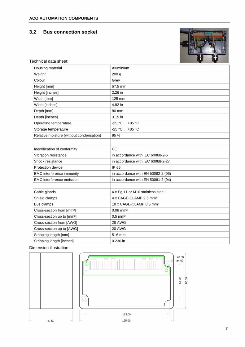
3.2 Bus connection socket
Technical data sheet: Housing material Aluminium Weight 200 g Colour Grey Height [mm] 57.5 mm Height [inches] 2.26 in Width [mm] 125 mm Width [inches] 4.92 in Depth [mm] 80 mm Depth [inches] 3.15 in Operating temperature -25 °C ... +85 °C Storage temperature -25 °C ... +85 °C Relative moisture (without condensation) 95 %
Identification of conformity CE Vibration resistance in accordance with IEC 60068-2-6 Shock resistance in accordance with IEC 60068-2-27 Protection device IP 66 EMC interference immunity in accordance with EN 50082-2 (96) EMC interference emission in accordance with EN 50081-2 (94) Cable glands 4 x Pg 11 or M16 stainless steel Shield clamps 4 x CAGE-CLAMP 2.5 mm² Bus clamps 18 x CAGE-CLAMP 0.5 mm² Cross-section from [mm²] 0.08 mm² Cross-section up to [mm²] 0.5 mm² Cross-section from [AWG] 28 AWG Cross-section up to [AWG] 20 AWG Stripping length [mm] 5 -6 mm Stripping length [inches] 0.236 in
Dimension illustration:
113.00
125.00
52.0
0
57.50
80.0
0
ø8.00ø4.00
7
ACO AUTOMATION COMPONENTS Technical data
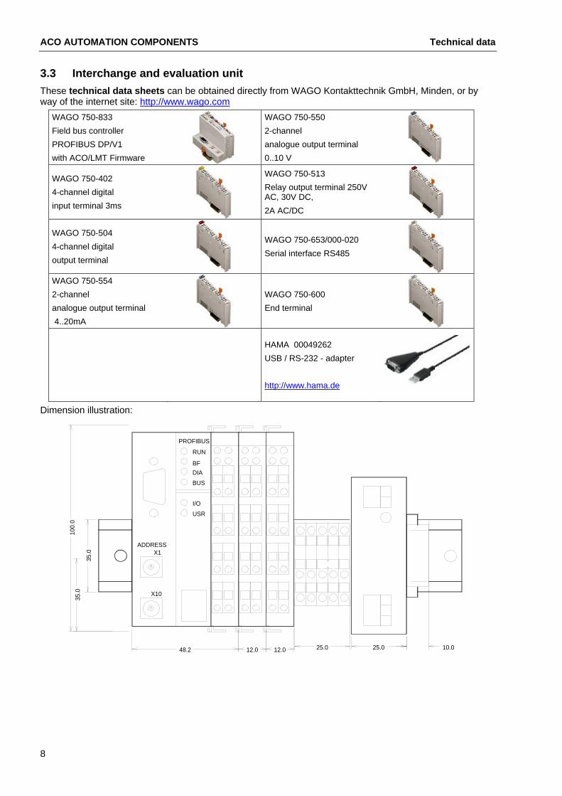
3.3 Interchange and evaluation unit These technical data sheets can be obtained directly from WAGO Kontakttechnik GmbH, Minden, or by way of the internet site: http://www.wago.com
WAGO 750-833 WAGO 750-550 Field bus controller 2-channel PROFIBUS DP/V1 analogue output terminal with ACO/LMT Firmware 0..10 V
WAGO 750-513 WAGO 750-402 Relay output terminal 250V AC, 30V DC, 4-channel digital
input terminal 3ms 2A AC/DC
WAGO 750-504 WAGO 750-653/000-020
4-channel digital Serial interface RS485
output terminal
WAGO 750-554 2-channel WAGO 750-600 analogue output terminal End terminal 4..20mA
HAMA 00049262 USB / RS-232 - adapter
http://www.hama.de
Dimension illustration:
12.0
ADDRESS
35.0
100.
0
48.2
35.0 X10
X1
DIA
USR
BUS
RUN
I/O
BF
PROFIBUS
25.025.012.0 10.0
8
ACO AUTOMATION COMPONENTS
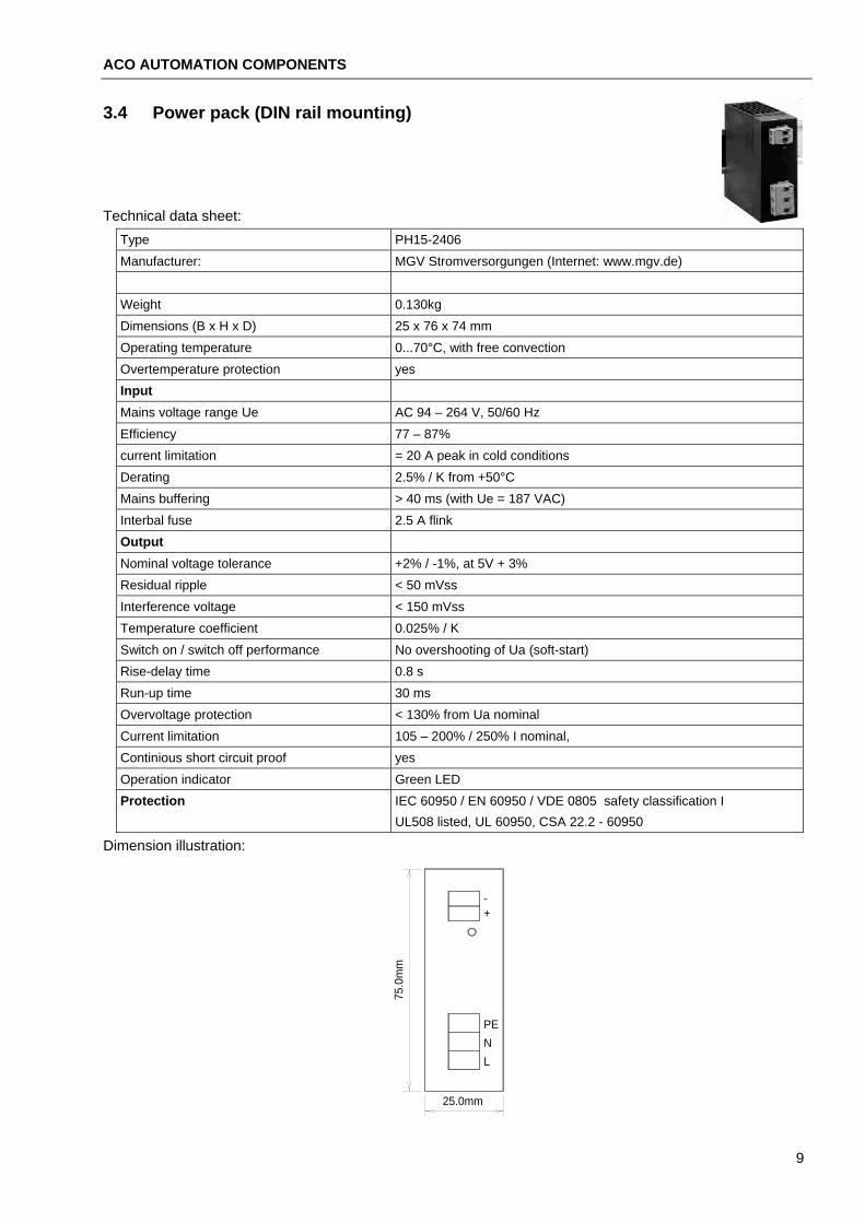
3.4 Power pack (DIN rail mounting)
Technical data sheet: Type PH15-2406 Manufacturer: MGV Stromversorgungen (Internet: www.mgv.de) Weight 0.130kg Dimensions (B x H x D) 25 x 76 x 74 mm Operating temperature 0...70°C, with free convection Overtemperature protection yes Input Mains voltage range Ue AC 94 – 264 V, 50/60 Hz Efficiency 77 – 87% current limitation = 20 A peak in cold conditions Derating 2.5% / K from +50°C Mains buffering > 40 ms (with Ue = 187 VAC) Interbal fuse 2.5 A flink Output Nominal voltage tolerance +2% / -1%, at 5V + 3% Residual ripple < 50 mVss Interference voltage < 150 mVss Temperature coefficient 0.025% / K Switch on / switch off performance No overshooting of Ua (soft-start) Rise-delay time 0.8 s Run-up time 30 ms Overvoltage protection < 130% from Ua nominal Current limitation 105 – 200% / 250% I nominal, Continious short circuit proof yes Operation indicator Green LED Protection IEC 60950 / EN 60950 / VDE 0805 safety classification I UL508 listed, UL 60950, CSA 22.2 - 60950
Dimension illustration:
25.0mm
75.0
mm
NL
PE
-+
9
ACO AUTOMATION COMPONENTS Technical data
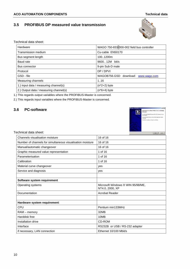
3.5 PROFIBUS DP measured value transmission
Technical data sheet: Hardware WAGO 750-833/000-002 field bus controller
Transmission medium Cu-cable EN50170 Bus segment length 100..1200m Baud rate 9600.. 12M bit/s Bus connector 9-pin Sub-D male Protocol DP / DPVI GSD - file WAGOB756.GSD download: www.wago.comMeasuring channels 1..16 1.) input data / measuring channel(s) (n*2+2) byte 2.) Output data / measuring channel(s) (n*6+4) byte
1.) This regards output variables where the PROFIBUS-Master is concerned. 2.) This regards input variables where the PROFIBUS-Master is concerned.
3.6 PC-software
Technical data sheet: Channels visualisation moisture 16 of 16 Number of channels for simultaneous visualisation moisture 16 of 16 Manual/automatic changeover 16 of 16 Graphic measured value representation 1 of 16 Parameterisation 1 of 16 Calibration 1 of 16 Material curve changeover yes Service and diagnosis yes Software system requirement
Microsoft Windows ® WIN 95/98/ME, NT4.0, 2000, XP
Operating systems
Documentation Acrobat Reader Hardware system requirement: CPU Pentium min133MHz RAM – memory 32MB Harddisk free 10MB Installation drive CD-ROM Interface RS232B or USB / RS-232 adapter if necessary, LAN connection Ethernet 10/100 Mbit/s
10
ACO AUTOMATION COMPONENTS
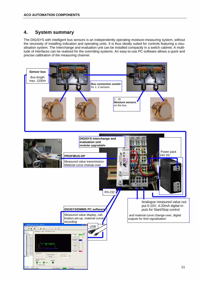
4. System summary The DIGISYS with intelligent bus sensors is an independently operating moisture-measuring system, without the necessity of installing indication and operating units. It is thus ideally suited for controls featuring a visu-alisation system. The Interchange and evaluation unit can be installed compactly in a switch cabinet. A multi-tude of interfaces can be realised for the overriding systems. An easy-to-use PC-software allows a quick and precise calibration of the measuring channel.
1.. 16 Moisture sensors on the bus
Sensor bus
Bus length max. 1200m
Bus connection socket-for 1..2 sensors
DIGISYS Interchange and evaluation unit modular upgradable
Power pack 24V DCPROFIBUS-DP
Measured value transmission-Material curve change-over
DIGISYS/DMMS PC software
Measured value display, cali-bration,set-up, material curves, recording
Analogue measured value out-put 0-10V, 4-20mA digital in-puts for Start/Stop control
RS-232
and material curve change-over, digital outputs for limit signalisation
USB
11
ACO AUTOMATION COMPONENTS DMMS moisture sensor
5. DMMS moisture sensor The DMMS sensor is a so-called "intelligent sensor", thus, the installed µ-processor allows complete solving of the problem in one component, as well as an expanded functionality.
• Direct digital measuring procedure
• Calibration data memory
• Linearisation
• Inspection of thresholds
• Start / Stop control
• Mean value calculation
• Temperature measurement
• Temperature compensation
• Material-specific adjustment
• Digital interface / networking
• Error report
A precise calibration at the factory allows complete reproducibility over a wide temperature range. The costly material-specific adjustment therefore is also possible for wider measuring channels and no readjustment is necessary, in the case the sensor is replaced.
The sensor receives a measuring task from the DIGISYS Interchange and evaluation unit and makes avail-able the ready-processed measuring result available at the precise required time. The data transfer is re-duced to a minimum and the resources of controls which have a higher priority are less burdened.
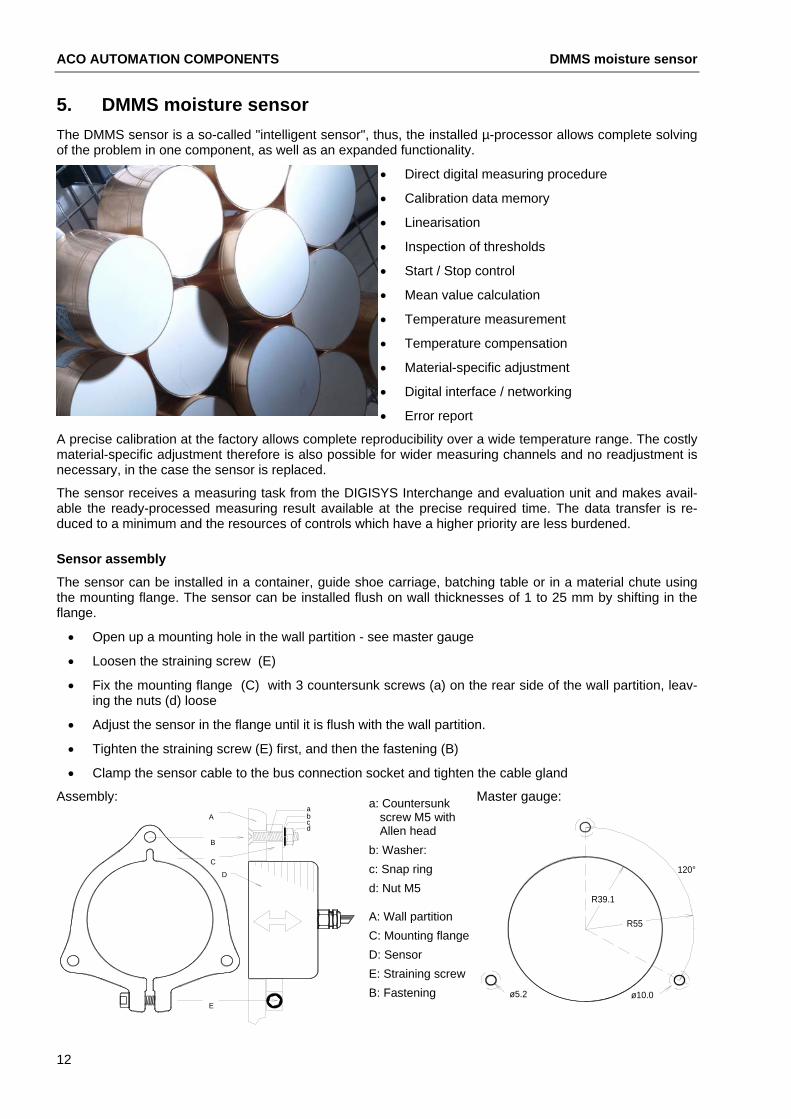
Sensor assembly
The sensor can be installed in a container, guide shoe carriage, batching table or in a material chute using the mounting flange. The sensor can be installed flush on wall thicknesses of 1 to 25 mm by shifting in the flange.
• Open up a mounting hole in the wall partition - see master gauge
• Loosen the straining screw (E)
• Fix the mounting flange (C) with 3 countersunk screws (a) on the rear side of the wall partition, leav-ing the nuts (d) loose
• Adjust the sensor in the flange until it is flush with the wall partition.
• Tighten the straining screw (E) first, and then the fastening (B)
• Clamp the sensor cable to the bus connection socket and tighten the cable gland
Master gauge: Assembly:
a: Countersunk screw M5 with Allen head
E
D
C
B
Acd
ab
ø10.0
120°
R55
ø5.2
R39.1
b: Washer: c: Snap ring d: Nut M5
A: Wall partition C: Mounting flangeD: Sensor E: Straining screw B: Fastening
12

ACO AUTOMATION COMPONENTS
CAUTION Damage to the system.
• Do not open the cable clamp on the sensor.
• Do not strike the ceramic wear shield directly with a hammer.
• Install the sensor flush to prevent material encrustations or premature wear.
• Hot water from evaporation in the silo damages the sensor or leads to measuring discrepancies.
• The temperature inside the sensor housing may not exceed 80°C.
• The sensor may not be installed in immediate proximity to vibratory discharge aids (vibrators).
• When replacing sensors, do not cut away the connecting cable of the old sensor.
• When filling the silo for the first time, ensure that the sensor is protected against falling rocks.
• A mounting flange installed at a tilt in the sensor can fall out if it becomes overloaded.
• The 3 fastening screws (a) and the straining screw (E) must be made of stainless steel.
Maintenance
• Correct functioning of the measuring channel (s) must undergo a daily inspection.
• The wear shield made of ceramic must be examined for damage and wear
• Remove any material which adheres to the ceramic wear shield.
• An even flow of material with sufficient over-layer (>50mm) must be present.
• The moisture measuring value must be verified via a laboratory test. A sufficient quantity of material, representative of the mix, is extracted and at the same time the moisture measuring value or the digit value is recorded. If the deviations prove too great, the calibration curves can be adjusted. (see PC soft-ware or indication and parameterisation module)
Replacing the sensor
Electric shock!
Connection of the plant and all tasks to the electrical equip-ment may only be carried out by an electrical specialist.
DANGER Moving machine parts! The sensor can be fitted in the immediate proximity of mov-ing machine parts. Switch off the machine!
1. Cut the voltage supply to the measuring system.
2. Open the bus connection socket, loosen the cable clamp and unclamp the sensor cable.
3. First loosen the fastening (B) and then loosen the straining screw (E) until the mounting flange releases the sensor.
4. Install a new sensor in the mounting flange, adjust. and tighten the straining screw (E).
5. Tighten the fastening (B).
6. Clamp the sensor cable, tighten the cable clamp and connect the bus connection socket.
7. Clean and dry the surface of the sensor.
8. Start up the measuring system once again
9. Read off the digit value for the air and carry out an offset. A recalibration of the measuring channel is then not necessary. (see PC software or APM)
13

ACO AUTOMATION COMPONENTS Bus connection socket
14
6. Bus connection socket The ACO bus connection socket facilitates installation of the sensor bus:
• Protection type IP66
• Connection of 1 or 2 moisture sensors
• Connection of 1 or 2 bus lines
• Bus termination
• Allocation of sensor address
• Fine protection against lightning
• CAGE CLAMP connection technology
• 4 cable clamps
Assembly of the bus connection socket
1. Fasten the socket using suitable screws through the holes B.
2. Connect 1 or 2 sensors, the white and grey wires serve to determine the sensor address.
3. Connect the cable from the sensor bus, at the last socket attach clamps A and B as bus con-nection instead of 120 Ohm resistance.
4. All shieldings on shield clamp
5. Tighten the cable glands.
6. Connection socket - mount the cover
Sensor
+ - A B Kanal Nr.
gr
ws
gn
ge
rsbn
B
Sensorbus
+ - A B
BUSC1
V1
Sensor
R7
+ - A B
BUS
R8
R1
R2
R3
R4 Schirm
+ - A B Kanal Nr.
gr
ws
gn
ge
rsbn
R5
R6
Sensorbus
BV2
Sensor Sensor cable connection address + - A B Channel no.
1 bn rs ge gn ws gr 2 bn rs ge gn ws gr 3 bn rs ge gn ws gr 4 bn rs ge gn ws gr 5 bn rs ge gn ws gr 6 bn rs ge gn ws o----o gr 7 bn rs ge gn ws gr
Do not set any double
sensor addresses! Sensor cable length is a
maximum 6m!
8 bn rs ge gn ws gr Wire colours{XE 9 bn rs ge gn ws grbn brown 10 bn rs ge gn ws o-------o grrs pink 11 bn rs ge gn ws o----o gr
BUS
120
- A B+
ge yellow 12 bn rs ge gn ws o----o grgn green 13 bn rs ge gn ws grFor the last connection socket, set a resistance
with 120 ohms between clamps A and B . ws white 14 bn rs ge gn ws o----o grgr grey 15 bn rs ge gn ws gr
Circuit diagram:
o----o Bridge 16 bn rs ge gn ws gr
Schirm / shield
Sensorbus
+ - A A B+ -B
rs gnge ws
bn g r
Sensor
R2
2k
R1
1k
R4
8k
R3
4k
V1
10N
391K
C1
10n
gr
A B+ -
rs gnge ws
bn
Sensor
R5
1k
R6
2k
R7
4k
R8
8k
A+ - B
Sensorbus
V2
10N
391 K
ACO AUTOMATION COMPONENTS
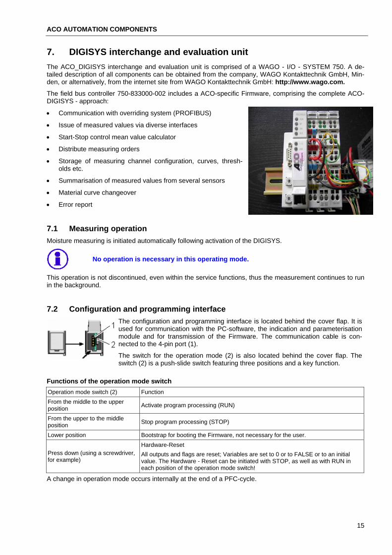
7. DIGISYS interchange and evaluation unit The ACO_DIGISYS interchange and evaluation unit is comprised of a WAGO - I/O - SYSTEM 750. A de-tailed description of all components can be obtained from the company, WAGO Kontakttechnik GmbH, Min-den, or alternatively, from the internet site from WAGO Kontakttechnik GmbH: http://www.wago.com.
The field bus controller 750-833000-002 includes a ACO-specific Firmware, comprising the complete ACO-DIGISYS - approach:
• Communication with overriding system (PROFIBUS)
• Issue of measured values via diverse interfaces
• Start-Stop control mean value calculator
• Distribute measuring orders
• Storage of measuring channel configuration, curves, thresh-olds etc.
• Summarisation of measured values from several sensors
• Material curve changeover
• Error report
7.1 Measuring operation Moisture measuring is initiated automatically following activation of the DIGISYS.
No operation is necessary in this operating mode.
This operation is not discontinued, even within the service functions, thus the measurement continues to run in the background.
7.2 Configuration and programming interface The configuration and programming interface is located behind the cover flap. It is used for communication with the PC-software, the indication and parameterisation module and for transmission of the Firmware. The communication cable is con-nected to the 4-pin port (1).
The switch for the operation mode (2) is also located behind the cover flap. The switch (2) is a push-slide switch featuring three positions and a key function.
Functions of the operation mode switch Operation mode switch (2) Function From the middle to the upper position Activate program processing (RUN)
From the upper to the middle position Stop program processing (STOP)
Lower position Bootstrap for booting the Firmware, not necessary for the user. Hardware-Reset
Press down (using a screwdriver, for example)
All outputs and flags are reset; Variables are set to 0 or to FALSE or to an initial value. The Hardware - Reset can be initiated with STOP, as well as with RUN in each position of the operation mode switch!
A change in operation mode occurs internally at the end of a PFC-cycle.
15

ACO AUTOMATION COMPONENTS DIGISYS interchange and evaluation unit
7.3 PROFIBUS DP Moisture and temperature values, status and error reports from all 16 channels can be read from the control-ler via the PROFIBUS DP, and all control signals such as Start, Fine and Manual can be set.
Detailed description 750-121 and a supplement for 750-333/-833 PROFIBUScan be ob-tained from the WAGO Kontakttechnik GmbH company in Minden, or on their internet site:http://www.wago.com .
All documentation regarding the PROFIBUS is available on the PROFIBUS user organisation internet page: www.PROFIBUS.com.
16
ACO AUTOMATION COMPONENTS
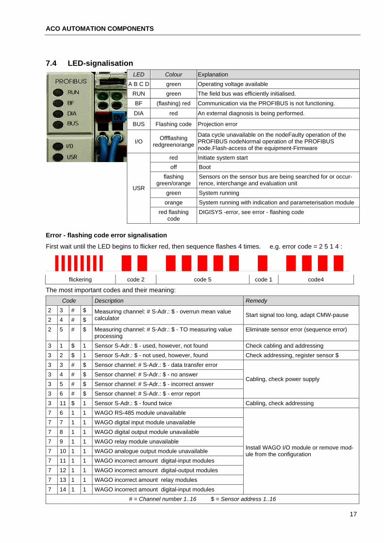
7.4 LED-signalisation Explanation LED Colour
A B C D green Operating voltage available RUN green The field bus was efficiently initialised.
BF (flashing) red Communication via the PROFIBUS is not functioning.
DIA red An external diagnosis is being performed.
BUS Flashing code Projection error
Data cycle unavailable on the nodeFaulty operation of the PROFIBUS nodeNormal operation of the PROFIBUS node.Flash-access of the equipment-Firmware
Offflashing redgreenorangeI/O
red Initiate system start off Boot
flashing green/orange
Sensors on the sensor bus are being searched for or occur-rence, interchange and evaluation unit
green System running USR
orange System running with indication and parameterisation module red flashing
code DIGISYS -error, see error - flashing code
Error - flashing code error signalisation
First wait until the LED begins to flicker red, then sequence flashes 4 times. e.g. error code = 2 5 1 4 :
flickering code 2 code 5 code 1 code4
The most important codes and their meaning: Code Description Remedy
2 3 # $ 2 4 # $
Measuring channel: # S-Adr.: $ - overrun mean value calculator Start signal too long, adapt CMW-pause
Measuring channel: # S-Adr.: $ - TO measuring value processing
2 5 # $ Eliminate sensor error (sequence error)
3 1 $ 1 Sensor S-Adr.: $ - used, however, not found Check cabling and addressing 3 2 $ 1 Sensor S-Adr.: $ - not used, however, found Check addressing, register sensor $ 3 3 # $ Sensor channel: # S-Adr.: $ - data transfer error 3 4 # $ Sensor channel: # S-Adr.: $ - no answer 3 5 # $ Sensor channel: # S-Adr.: $ - incorrect answer
Cabling, check power supply
3 6 # $ Sensor channel: # S-Adr.: $ - error report 3 11 $ 1 Sensor S-Adr.: $ - found twice Cabling, check addressing 7 6 1 1 WAGO RS-485 module unavailable 7 7 1 1 WAGO digital input module unavailable 7 8 1 1 WAGO digital output module unavailable 7 9 1 1 WAGO relay module unavailable 7 10 1 1 WAGO analogue output module unavailable 7 11 1 1 WAGO incorrect amount digital-input modules
Install WAGO I/O module or remove mod-ule from the configuration
7 12 1 1 WAGO incorrect amount digital-output modules 7 13 1 1 WAGO incorrect amount relay modules 7 14 1 1 WAGO incorrect amount digital-input modules
# = Channel number 1..16 $ = Sensor address 1..16
17
ACO AUTOMATION COMPONENTS DIGISYS interchange and evaluation unit
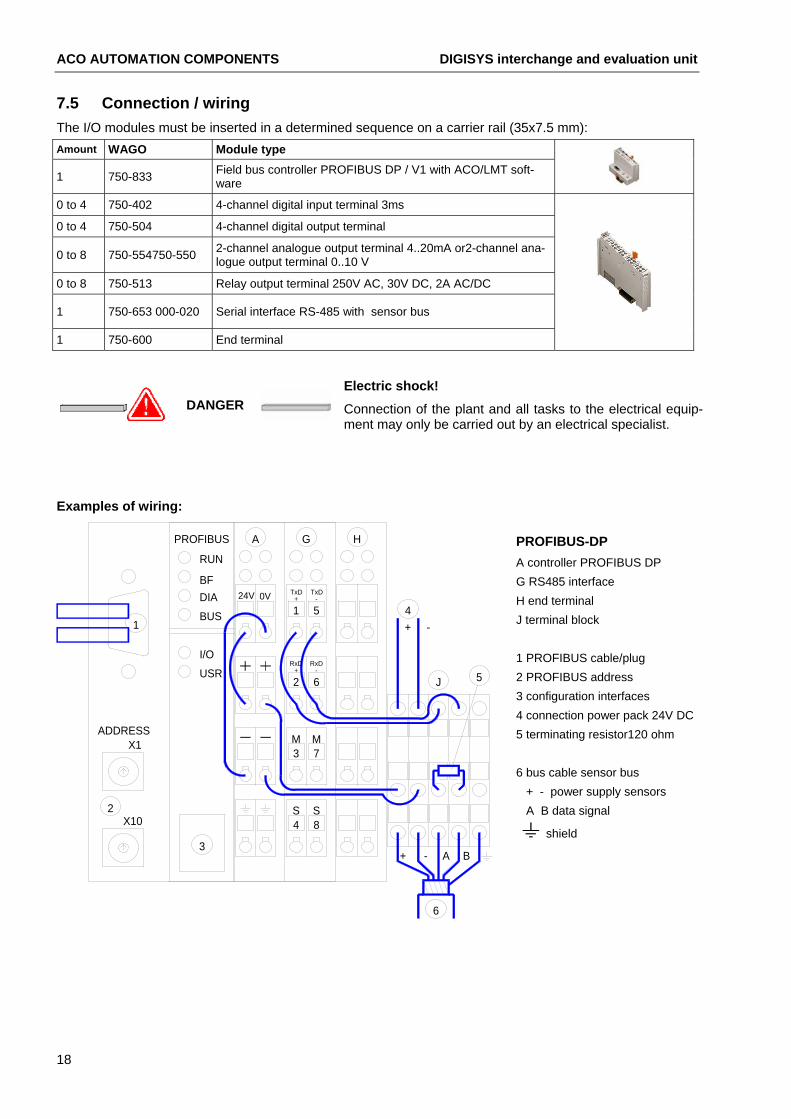
7.5 Connection / wiring The I/O modules must be inserted in a determined sequence on a carrier rail (35x7.5 mm):
WAGO Module type Amount
Field bus controller PROFIBUS DP / V1 with ACO/LMT soft-ware 1 750-833
0 to 4 750-402 4-channel digital input terminal 3ms 0 to 4 750-504 4-channel digital output terminal
2-channel analogue output terminal 4..20mA or2-channel ana-logue output terminal 0..10 V 0 to 8 750-554750-550
0 to 8 750-513 Relay output terminal 250V AC, 30V DC, 2A AC/DC
1 750-653 000-020 Serial interface RS-485 with sensor bus
1 750-600 End terminal
Electric shock! DANGER Connection of the plant and all tasks to the electrical equip-
ment may only be carried out by an electrical specialist.
Examples of wiring:
6
X102
4S
3
8S
ADDRESSX1
3M
7M
+ - A B
GPROFIBUS A H
1
2USR
I/ORxD
+
6
RxD-
TxDBFDIA
BUS
24V 0V +
1
RUN
-
5
TxD
+ -
J 5
4
PROFIBUS-DP A controller PROFIBUS DP G RS485 interface H end terminal J terminal block 1 PROFIBUS cable/plug 2 PROFIBUS address 3 configuration interfaces 4 connection power pack 24V DC 5 terminating resistor120 ohm 6 bus cable sensor bus + - power supply sensors A B data signal
shield
18

ACO AUTOMATION COMPONENTS
ADDRESS
2
- +
1
+ -
6
X103
4SS
4S8 8
S
X13M0V 0V
3 7 7M
- A B+
PROFIBUS GA D H
USR
I/O
622 6
RxD+
RxD-
24VBFDIA
BUS
RUN
0V +
1
TxD+A1+A21 5
TxD-
5-+
J 5
4
with output 2 x 4..20mA A controller PROFIBUS DP D output terminal 4..20mA G RS485 interface H end terminal J terminal block 1 cable 4..20mA channel 1 2 cable 4..20mA channel 2 3 configuration interfaces 4 connection power pack 24V DC 5 terminating resistor 120 ohm 6 bus cable sensor bus + - power supply sensors A B data signal sensor bus
shield
X10
ADDRESSX1
8721+ - - +
6
S4
S8
SS4 8
3
0V 0V3 7
M M3 7
BA-+
PROFIBUS A D G HF
USR
I/O
2 6
RxD+
RxD-
2 6S2bS1b
2 6
0VBFDIABUS
24V
RUN
+A1+A21 5 5
-TxD
1+
TxDS2aS1a1 5
+ -
J 5
4
2x 4..20 mA, 2x relay contact A controller PROFIBUS DP D output terminal 4..20mA F relay output terminal G RS485 interface H end terminal J terminal block 1 cable 4..20mA channel 1 2 cable 4..20mA channel 2 3 configuration interfaces 4 connection power pack 24V DC 5 terminating resistor 120 ohm 6 bus cable sensor bus 7 connection contact 1 8 connection contact 2
shield
X10
ADDRESSX1
Gnd
Sta r
t2
Star
t3
Star
t4
Sta r
t1
Com
-
F ein
1
16
8
E3E3 E44 8 4
S SE48 4 8
3
A2A1
3 7 3M M
7 3 7
SS4 8
S4
S8
+ - A B
A3 A4
M M3 7
M M3 7
PROFIBUS GBA B HE E
+A2
USRI/O
2 6 2 6 2 6
0VBFDIABUS
24V E1E1 E21 5 1
+A1E25 1 5
RUN
-+
RxD+
RxD-
2 62 6 5J
5-
TxD
1+
TxD+A2+A11 5 4
4 x output 0..10V , 4 x start input, 1x fine input A controller PROFIBUS DP B input terminals E analogue output terminals G RS485 interface H end terminal J terminal block 1 control cable Start and fine signal 3 configuration interface 4 connection power pack 24V DC 5 terminating resistor 120 ohm 6 bus cable sensor bus 7 connection contact 1
8 cable analogue outputs, Shield
19

ACO AUTOMATION COMPONENTS PC-Software DMMS/DIGISYS
8. PC-Software DMMS/DIGISYS The multi-lingual PC-Software DMMS/DIGISYS allows the possibility of connection to the interchange and evaluation unit. Configuration interface A is connected with the communication cable B to serial interface C of a PC/ notebook. In the event that the PC does not feature a serial interface, please find a „USB RS232 serial adapter“, included in delivery, and follow the operating instructions of the manufacturer.
Use USB adapter where
B
C
COM1
A
X10
PROFIBUS
ADDRESSX1
USRI/O
BFDIABUS
RUNFunctionality: required: • Measured value display 16 channels
• Configuration of the channels
• Calibrating device
• Measured value simulation
• Material changeover
• Record measured values
• Network connection
• Diagnosis
8.1 Installation Start the English language version installation program „setupXXX.exe“ on the CD-ROM.
Set-up has been initiated - click „Next“ Select „I accept the agreement“ Select target Drive / directory
Select entry in the start menu Optional quick-start links Details correct? - Click on „Install“
The software is then installed on the PC.
Start program
The program can now be started from the start menu or via the links on the „Desktop“.
The user name „Administrator“ is to be entered following installation.
No password is assumed, simply click on „OK“.
20
ACO AUTOMATION COMPONENTS
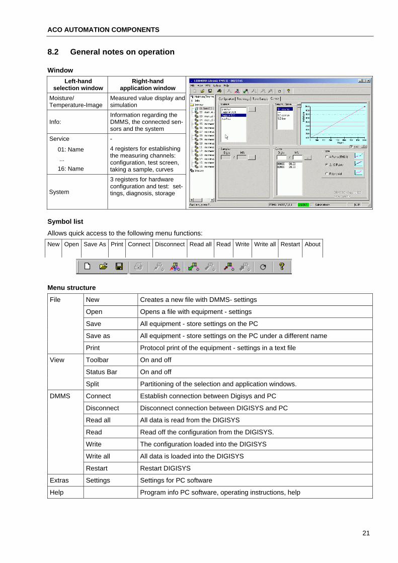
8.2 General notes on operation
Window Left-hand
selection window Right-hand
application window Moisture/ Temperature-Image
Measured value display and simulation Information regarding the DMMS, the connected sen-sors and the system
Info:
Service - 4 registers for establishing the measuring channels: configuration, test screen, taking a sample, curves
01: Name ... 16: Name
3 registers for hardware configuration and test: set-tings, diagnosis, storage System
Symbol list
Allows quick access to the following menu functions: New Open Save As Print Connect Disconnect Read all Read Write Write all Restart About
Menu structure
New Creates a new file with DMMS- settings File
Open Opens a file with equipment - settings
Save All equipment - store settings on the PC
Save as All equipment - store settings on the PC under a different name
Print Protocol print of the equipment - settings in a text file
Toolbar On and off View
Status Bar On and off
Split Partitioning of the selection and application windows.
Connect Establish connection between Digisys and PC DMMS
Disconnect Disconnect connection between DIGISYS and PC
Read all All data is read from the DIGISYS
Read Read off the configuration from the DIGISYS.
Write The configuration loaded into the DIGISYS
Write all All data is loaded into the DIGISYS
Restart Restart DIGISYS
Extras Settings Settings for PC software
Help Program info PC software, operating instructions, help
21

ACO AUTOMATION COMPONENTS PC-Software DMMS/DIGISYS
8.3 Extras / Settings Applies for the settings for the PC-software and not the DIGISYS interchange and evaluation unit.
Select the COM-port (serial interface): select COM1..8 or LAN -connection to interchange and evaluation unit.
Select Language menu
Separator for table values in *.csv text file with „Record take sample“
License code for activating PROFIBUS{XE "PROFIBUS"}
Determine userlevel and establish passwords for program start:
1 2 3 4 5 View configuration x x x x x Manual / automatic changeover x x x x Material-specific adjustment x x x
adapt measuring channels x x x
1=Observer 2=User 3=Maintenance personnel 4=Planning engineer 5=Administrator install measuring channels x x
User and passwords x
Menu DMMS / connect
The configuration interface must be connected with the communication cable and the serial interface (COM-port) of the PC. Menu connect DMMS
or click on „ “.
When connection has been established, read the configuration DIGISYS by clicking on „Yes“.
Menu DMMS / write
Modifications to the configuration only become effective if they are written in the DIGISYS interchange and evaluation unit.
Menu DMMS write or click on „ “.
Confirm the writing by clicking on „Yes“.
8.4 Info Prog. info: Sensor info: interchange and evalua-tion unit
All recognised sensors 1..16
System ID: identification Adr.: Sensor bus address
SV: Software version SN: Serial number
HV: Hardware version HV: Hardware version
Date: program date SV: Software version
SN: Serial number DT: Date of factory calibration
Site:
Storage of system-specific information. The entries have no influence on the measurements.
22
ACO AUTOMATION COMPONENTS
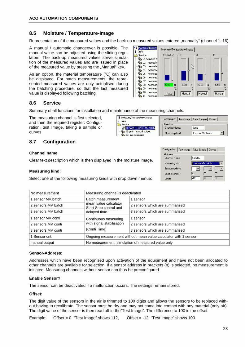
8.5 Moisture / Temperature-Image Representation of the measured values and the back-up measured values entered „manually“ (channel 1..16).
A manual / automatic changeover is possible. The manual value can be adjusted using the sliding regu-lators. The back-up measured values serve simula-tion of the measured values and are issued in place of the measured value by pressing the „Manual“ key.
As an option, the material temperature [°C] can also be displayed. For batch measurements, the repre-sented measured values are only actualised during the batching procedure, so that the last measured value is displayed following batching.
8.6 Service Summary of all functions for installation and maintenance of the measuring channels.
The measuring channel is first selected, and then the required register: Configu-ration, test Image, taking a sample or curves.
8.7 Configuration
Channel name
Clear text description which is then displayed in the moisture image.
Measuring kind:
Select one of the following measuring kinds with drop down menue: No measurement Measuring channel is deactivated 1 sensor MV batch 1 sensor 2 sensors MV batch 2 sensors which are summarised
Batch measurement mean value calculator Start-Stop control and
3 sensors MV batch 3 sensors which are summarised delayed time 1 sensor MV conti 1 sensor 2 sensors MV conti 2 sensors which are summarised
Continuous measuring with signal stabilisation (Conti Time) 3 sensors MV conti 3 sensors which are summarised
1 Sensor cnt. Ongoing measurement without mean value calculator with 1 sensor manual output No measurement, simulation of measured value only
Sensor-Address:
Addresses which have been recognised upon activation of the equipment and have not been allocated to other channels are available for selection. If a sensor address in brackets (n) is selected, no measurement is initiated. Measuring channels without sensor can thus be preconfigured.
Enable Sensor?
The sensor can be deactivated if a malfunction occurs. The settings remain stored.
Offset:
The digit value of the sensors in the air is trimmed to 100 digits and allows the sensors to be replaced with-out having to recalibrate. The sensor must be dry and may not come into contact with any material (only air). The digit value of the sensor is then read off in the“Test Image”. The difference to 100 is the offset.
Example: Offset = 0 “Test Image” shows 112, Offset = -12 “Test Image” shows 100
23

ACO AUTOMATION COMPONENTS PC-Software DMMS/DIGISYS
Batching cross section:
Allows weighted mean value calculation, as well as a curve changeover with fine batching. Coarse flow = fine flow No curve changeover
Fine flow = 0 Discontinuation of the measurement with fine signal, only the coarse flow is measured Coarse flow > fine flow Curve changeover with fine batching, the fine flow delivers a different measuring signal
Examples:
One sensor, no coarse-fine changeover:
One sensor, coarse-fine changeover via material flow reduction (1/2-open position):
Sensor1 measures coarse flow only, both sensors no curve changeover
Sensor1 measures coarse flow only, Sensor2 features curve changeover with fine batching as the fine flow is reduced by the 1/2-open position.
A pulsating fine batching can not be measured.
Range:
Range for the issue of measured values and display in whole percent units!
Lower Limit / Upper Limit:
The thresholds concern the working range of the mean value calculator. A stray value or an interruption in the material flow is therefore not in-cluded in the mean value. In the „..MV conti“ measuring kind, this halt function can be deactivated as required. „Hold“ will then not be reset.
Delay-Time:
The mean value calculation is initiated when the measured value is within the thresholds and a delay time has elapsed. The material flow may undergo „transient oscillation“ during the delay time. The duration of the required delay time can be established via "Take sample".
Conti-Time:
Memory depth of the continuous mean value calculation. A larger value effects a stabilisation of the measur-ing value, however also a signal delay in the measuring kinds „..MV conti“. Set the value as low as possible!
Digital input
The function of a digital input must be defined prior to utilisation. Undefined input numbers are indicated in brackets.
In „System/Settings“ for Start-Stop control of the „Start“ mean value calculator, select „Fine“ for curve changeover during fine batching. Type either Mx^1, Mx^2, Mx^4 or Mx^8 for material curve changeover.
For measuring kinds „.. MV batch“, the start signals and fine sig-nals are conveyed via the PROFIBUS or via digital inputs.
The start signal must be present throughout the entire batching procedure.
t
Start signal:(Level = H) the fine signal is present during the fine batching procedure:
(Level = L) the fine signal is not present during the fine batching procedure:
24
ACO AUTOMATION COMPONENTS
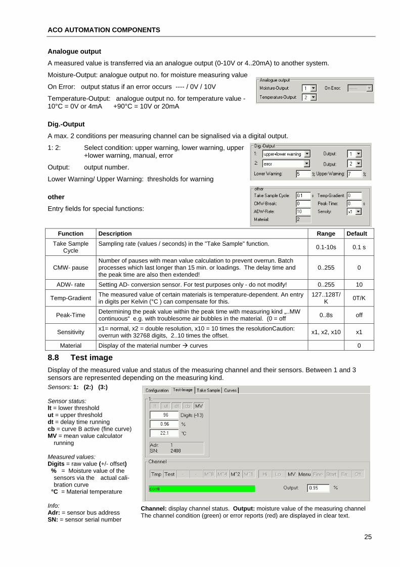
Analogue output
A measured value is transferred via an analogue output (0-10V or 4..20mA) to another system.
Moisture-Output: analogue output no. for moisture measuring value
On Error: output status if an error occurs ---- / 0V / 10V
Temperature-Output: analogue output no. for temperature value -10°C = 0V or 4mA +90°C = 10V or 20mA
Dig.-Output
A max. 2 conditions per measuring channel can be signalised via a digital output.
1: 2: Select condition: upper warning, lower warning, upper +lower warning, manual, error
Output: output number.
Lower Warning/ Upper Warning: thresholds for warning
other
Entry fields for special functions:
Function Description Range Default Take Sample
Cycle Sampling rate (values / seconds) in the "Take Sample" function. 0.1-10s 0.1 s
Number of pauses with mean value calculation to prevent overrun. Batch processes which last longer than 15 min. or loadings. The delay time and the peak time are also then extended!
CMW- pause 0..255 0
ADW- rate Setting AD- conversion sensor. For test purposes only - do not modify! 0..255 10 The measured value of certain materials is temperature-dependent. An entry in digits per Kelvin (°C ) can compensate for this.
127..128T/K Temp-Gradient 0T/K
Determining the peak value within the peak time with measuring kind „..MW continuous“ e.g. with troublesome air bubbles in the material. (0 = off Peak-Time 0..8s off
x1= normal, x2 = double resolution, x10 = 10 times the resolutionCaution: overrun with 32768 digits, 2..10 times the offset. Sensitivity x1, x2, x10 x1
Material Display of the material number curves 0
8.8 Test image Display of the measured value and status of the measuring channel and their sensors. Between 1 and 3 sensors are represented depending on the measuring kind. Sensors: 1: (2:) (3:) Sensor status: lt = lower threshold ut = upper threshold dt = delay time running cb = curve B active (fine curve) MV = mean value calculator
running Measured values: Digits = raw value (+/- offset) % = Moisture value of the
sensors via the actual cali-bration curve
°C = Material temperature Info: Channel: display channel status. Output: moisture value of the measuring channel
The channel condition (green) or error reports (red) are displayed in clear text. Adr: = sensor bus address SN: = sensor serial number
25

ACO AUTOMATION COMPONENTS PC-Software DMMS/DIGISYS
8.9 Take sample To obtain a material-specific balance, it is necessary to take samples from the flowing material as the digits are being recorded. The weight moistures of the samples are determined in the laboratory by drying or via „Karl Fischer Titration“. When creating the calibration curves, the digits are allocated to the laboratory sam-ples.
Moving machine parts!
The samples, in most cases, must be taken in immediate prox-imity of the running machine parts. DANGER
Use a suitable device (sampler) and observe the valid acci-dent-prevention guidelines.
By Start
The next batching procedure is recorded in the „..MW batch“ measuring kind.
Recording Continuous
The recording is stopped or started immediately.
Connect Dots
The measuring points in the graph are connected with lines.
Delete
The recording is deleted via an additional confirmation.
Selecting signals
Using the buttons Digits, Moisture, Temp and Output, the representation of the signals in the graph can be switched on and off. When creating the calibration curves, only the graph Digits1.. 3 need to be switched on.
Evaluate
The quality of the recorded sample can be read off at the curve gradient. If this can be guaranteed, the range of the sample can be limited using both red dashed cursors. The mean value of all digit values between the cursors are displayed and yield the digit value of a sample. This value is to be noted (copy into clipboard) and allocated to the laboratory value of the sample in the "Curves" register. The sampling rate can be deter-mined under „Configuration / Take Sample Cycle “.
Storing in a file:
Using the Screen key, all measured values which are currently being dis-played in the graph can be stored in a text file (*.csv). The keys Rec and Pause allow a long-time recording of the measured values in a text file, optionally with +DateFehler! Textmarke nicht definiert., Time. A window featuring „Save file as“ opens so that a file name can be designated.
The data can be evaluated with another program, e.g.: with MS-EXCEL.
Example: Example: Text file with time, digits, moisture and temperature.
Graphic evalua-tion with Ms- Excel.
26

ACO AUTOMATION COMPONENTS
8.10 Curves The "Curves" feature provides a simple means of creating a suitable calibration curve from the established samples.
Material
Curves for different materials can be deposited in each measuring channel. Every material name represents its own set of curves. The materials can be administered via the "..." switch:
Add a new material: Determine the name, create a new curve set with default values and open Change Material
Designation: Only the material name is changed
Delete Material: Delete material name and curve set
Copy Material: Copy curve set into a clipboard
Paste Material: Insert curve set from clipboard
Sensor, curve
S1..S3 coarse S1..S3 fine:
selection and display of the curve in the curve set. 1 to 6 curves can be selected depending on the configuration.
Arrow keys: scaling the the graphic.
y=x: sets scaling of the y-axis automatically to 1/100 of the x-axis.
Curve, Type 4 Points
the most favourable calibration curve is ascertained from the sample list and the actual thresholds using an optimisation procedure, and determined by 4 points. This type is supported by all DMMS moisture sensors. The sample is only available for this curve type.
Furthermore, it is also possible to modify the curve directly. See curve type 2..10 points. The entered points must lead to a strictly monotonic function.
Refrain from using this possibility with the ACO_DMMS Sensor as with this method the curve points must be ascertained using the sample values and thresholds.
Sample list
The Digits ascertained with „Take sample“ are here allocated laboratory values. From these samples (digits / moistures), the calibration curves of the type "4 points (FMS1)" are created.
The samples can be administered via the " ... “ button:
Add Sample:
Enter Digits / M%, „..Insert sample“ the sample is added to the list and is displayed in the graphic.
Change Sample:
Mark a sample in the list. „...Modify sample“ edit Digits / M%, „Modify sample" once again.
Delete Sample(s):
Mark a sample in the list. „Delete sample“ the sam-ple is removed from the list.
Take over Curve:
Mark the sample in the list. „...Adopt the curve“ and a suitable 4-point curve is created.
Note! Point 1 and point 4 are the thresholds.
27

ACO AUTOMATION COMPONENTS PC-Software DMMS/DIGISYS
Curve, Type 2..10 Points
Evaluation of the samples is resulted on graph paper or via a table calculation system (e.g.: MS EXCEL). 2 data points (straight) or several data points can then be entered. The point list of the curve can be adminis-trated via the "..." switch:
Add Point
Change Point
Delete point
Take Over Curve:
Move Curve (Y)
Copy Curve
Paste-Curve
Digits / M% are entered in the list and the result-ing curve is displayed in the graphic
Mark the point, "... Change point", modify Digits and M%, then"... Change point" once again.
Mark the point in the list, "...delete point"
Adopt the curve resulted from the points, also displayed in the graphic
Shift the curve by +/- 0..5 %F. Small deviations in the measurement can thus be corrected quickly and efficiently, then "...Take Over Curve "
Copying the curve into clipboard and inserting the curve from clipboard allows simple transferral of a curve into another measuring channel.
Curve, Type Polynomial
The mathematic correlation between digits and moisture values can be ascertained using a table calculation system (e.g.: MS EXCEL). This correlation is represented by the digits 2 to 5 (coefficients). These coeffi-cients can then be entered as a curve via the "..." switch.
TakeOver Curve:
Edit Polynomial
Move Curve (Y)
Polynomial from String
Copy Curve
Paste Curve
Adopt the curve resulted from the points, also displayed in the graphic
„...Edit polynomial“, modify coefficients, then „... Edit polynomial“ once again
Shift the curve by +/- 0..5 %F. Small deviations in the measurement can thus be corrected quickly and efficiently, then "...Take Over Curve "
A polynomial can be imported via the MS-WINDOWS intermediate storage.
Copying the curve into clipboard and inserting the curve from clipboard allows simple transferral of a curve into another measuring channel.
Polynomial as character string with MS-EXCEL{XE "EXCEL"}{XE "MS-EXCEL"}
Create a table with digits and laboratory samples and highlight it – insert / diagram / point (xy)
highlight the data row in the diagram - diagram / insert trendline / type: polynomial 3rd order
highlight trendline - Format / highlighted trendline / options / show formula in the diagram.
highlight formula - Format / highlighted label / digits / science / decimal places: 5
highlight the text of the formula – Process / copy. Polynomial goes as a character string into the clipboard.
28
ACO AUTOMATION COMPONENTS
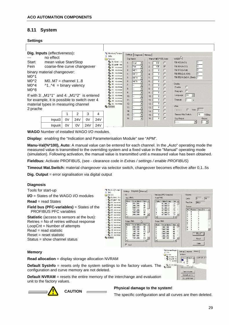
8.11 System
Settings
Dig. Inputs (effectiveness): --- no effect Start mean value Start/Stop Fein coarse-fine curve changeover binary material changeover: M0^1 M0^2 M0..M7 = channel 1..8 M0^4 ^1..^4 = binary valency M0^8 If with 3: „M1^1“ and 4: „M1^2“ is entered for example, it is possible to switch over 4 material types in measuring channel 2:prache
1 2 3 4 Input3 0V 24V 0V 24V Input4 0V 0V 24V 24V
WAGO Number of installed WAGO I/O modules.
Display: enabling the “Indication and Parameterisation Module” see “APM”.
Manu-Val(%*100), Auto: A manual value can be entered for each channel. In the „Auto“ operating mode the measured value is transmitted to the overriding system and a fixed value in the "Manual" operating mode (simulation). Following activation, the manual value is transmitted until a measured value has been obtained.
Fieldbus: Activate PROFIBUS, (see - clearance code in Extras / settings / enable PROFIBUS)
Timeout Mat.Switch: material changeover via selector switch, changeover becomes effective after 0,1..5s
Dig. Output = error signalisation via digital output
Diagnosis Tools for start-up I/O = States of the WAGO I/O modules Read = read States Field bus (PFC-variables) = States of the
PROFIBUS PFC variables Statistic (access to sensors at the bus): Retries = No of retries without response LoopCnt = Number of attempts Read = read statistic Reset = reset statistic Status = show channel status
Memory
Read allocation = display storage allocation NVRAM
Default SysInfo = resets only the system settings to the factory values. The configuration and curve memory are not deleted.
Default NVRAM = resets the entire memory of the interchange and evaluation unit to the factory values.
Physical damage to the system! CAUTION
The specific configuration and all curves are then deleted.
29

ACO AUTOMATION COMPONENTS PC-Software DMMS/DIGISYS
8.12 Example - install a measuring channel
Measuring problem
S1 S2 S1 S2
Sand is batched onto a weigher belt via dual discharge. Both discharge points are completely open for coarse batching, in the subsequent fine batching phase the 2nd discharge point half closes and the 1st discharge posi-tion closes completely. A sensor featuring bus address "1" is installed in the first discharge point and a sensor featuring bus address "2" is installed in the 2nd dis-charge point. The SPS signals (24V) of the batching control are wired as follows: "Components batching " to "Digital input 1" and "Fine" to "Digital input 4". Analogue output 1 should supply 0..10V for a measuring range of 0..20%. Measuring values above 2% and below 15 % moisture are permissible (thresholds).
coarse fine
Start-up
B
C
COM1
A
X10
PROFIBUS
ADDRESSX1
USR
I/O
BFDIA
BUS
RUN
1. Configuration interface A is connected with the communication cable B to serial interface C of a PC/ notebook.
2. Start the DIGISYS program and click on "Connect" in the icon bar. If the module is recognised, click on „YES“.
3. Click on „Info“. All sensors on the bus must be recognised
4. Select measuring channel 1: click in the selection window under Service "01:...." and select the "Configuration" register card.
5. Designate a channel name, select measuring kind "2 sensors MV batch" and enter the bus addresses of sensors"1" and "2". Enable both sensors (ticks)
6. Switch to the "Test-Image" register card. Dry the sensors using a towel. Ascertain the digits in air, note them down and calculate the offset (off-set = digits in air - 100).
7. Enter the offset in Configuration
8. Batching cross-section for coarse batching: both sensors : 100 dm² and for fine batching: sensor1: 0 dm² , sensor2: 50 dm²
9. The range for measuring value display and issue is 0..20% moisture
10. The thresholds must be within the measuring range. 11. An even flow of material has formed after 0.8s (delay time).
12. The start signal is at input 1, a changeover signal to fine curve is at input 4, Level = L signifies coarse 24V fine 0V
13. The moisture value is at analogue output 1 without error signalisation
30
ACO AUTOMATION COMPONENTS
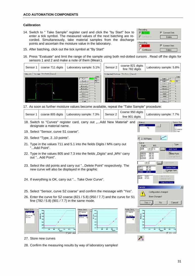
Calibration
14. Switch to " Take Sample" register card and click the "by Start" box to enter a tick symbol. The measured values of the next batching are re-corded. Simultaneously, take material samples from the discharge points and ascertain the moisture value in the laboratory.
15. After batching, click out the tick symbol at "By Start"
16. Press "Evaluate" and limit the range of the sample using both red-dotted cursors . Read off the digits for sensors 1 and 2 and make a note of them (Mean:).
Sensor 1 coarse 711 digits Laboratory sample: 5.1% coarse 821 digits fine 782 digits Sensor 2 Laboratory sample: 5.8%
17. As soon as further moisture values become available, repeat the "Take Sample" procedure:
Coarse 950 digits Sensor 1 coarse 805 digits Laboratory sample: 7.3% Sensor 2 Laboratory sample: 7.7%
fine 901 digits
18. Switch to "Curves" register card, carry out „...Add New Material“ and designate a material name.
19. Select "Sensor, curve S1 coarse".
20. Select "Type, 2..10 points". 21. Type in the values 711 and 5.1 into the fields Digits / M% carry out
"...Add Point".
22. Type in the values 805 and 7.3 into the fields „Digits“ and „M%“ carry out "...Add Point".
23. Select the old points and carry out "...Delete Point" respectively. The new curve will also be displayed in the graphic
24. If everything is OK, carry out "... Take Over Curve".
25. Select "Sensor, curve S2 coarse" and confirm the message with "Yes".
26. Enter the curve for S2 coarse (821 / 5.8) (950 / 7.7) and the curve for S1 fine (782 / 5.8) (901 / 7.7) in the same mode.
27. Store new curves 28. Confirm the measuring results by way of laboratory samples!
31

ACO AUTOMATION COMPONENTS PC-Software DMMS/DIGISYS
8.13 Error reports Incorrect entries
All errors which are recognised during operation of the PC software DMMS/DIGISYS are displayed in a separate window in clear text and must be confirmed.
DIGISYS error signalisation
Errors which are recognised by the DIGI-SYS interchange and evaluation unit are displayed via a flashing code (error code).
See interchange and evaluation unit LED-signalisation.
These errors are also listed in a separate window "DMMS error signalisation". The window then remains in the foreground and can be minimised as required.
8.14 Software versions
PC-Software
V2.2: First issue
V2.3: Digital output for error signalisation and sensor-reset, deactivation of Hold with continuous (upwards of sensor - V35), Online- Timeout from .ini-File (old: 500ms, fixed), take sample: show time difference.
V2.4: 8 COM- ports, copy / insert for curves and materials, LAN-support, user administration, cyclic re-cording in file with Take sample, hyperlink in Info box.
V2.5: Auxiliary system with Adobe Acrobat Reader PDF-file.
interchange and evaluation unit V2.0: First issue V2.2: APM support, error signalisation with digital output, analogue output and in moisture image 'E', system
data, material changeover with digital inputs, transfer actual material in channel status. V2.3: Digital output for sensor reset and error signalisation, deactivation of Hold with continuous
Sensor V32: Initial batch, V33: Offset in air, extend straight line to threshold V34: Temperature gradient V35: Deactivation of Hold with continuous, 2nd status byte, signal processing, even with CMW_Pause, acti-
vation delay 200ms, WDT immediately following activation, MTK with float, command timeout of 6.4s to 195ms
V36: Functional as with 35, but with processor AT89C51ED2 (byte mode) V37: Functional as with 35, but with processor AT89C51RB2 EEPROM in FLASH
32

ACO AUTOMATION COMPONENTS Spare-parts list
9. Spare-parts list Description: DMMS_Sensor Mounting flange with screw A4
Countersunk screw DIN7991 M5X 25 A2-70 Hexagonal nut EN24032 M 5 A2-70 Lock washer DIN 128 5 A2-70 Washer EN27089 5,3 A2-70
Bus connection socket
Cable gland M16x1.5 4.5-10MM Lock M16x1.5 Cheese-head screw ISO1207- AM 4X 12- 4.8 Lock washer DIN 128 Bus terminating resistor 0.5W 120R 1% +-10 Mounting plate, weldable 4x140x140
Cable sensor bus (Unitronic-bus LD 2 x 2 x 0.22 ) DIGISYS interchange and evaluation unit basic equipment
USB RS232 serial adapter Communication cable (WAGO 750-920)
Options: 4-channel digital input terminal 3ms (WAGO 750-402) 2-channel analogue output terminal 0..10V (WAGO 750-550) 2-channel analogue output terminal 4-20mA (WAGO 750-554) Relay output terminal 250 V AC, 30V DC, 2A AC/DC (WAGO 750-513) 4-channel digital output terminal 0.5A (WAGO 750-504) Plug-in power supply 24V/0.5A
PC-Software DMMS/DIGISYS
ACO_DMMS_DIGISYS operating instructions, German
ACO_DMMS_DIGISYS operating instructions, English
33


