Page 1
©2013 Waters Corporation 1
ACQUITY UPLC® Columns
Techniques for Maximizing Performance and Productivity
Esa Lehtorinne
[email protected]
Tel: +358-9-5659 6288 Fax: +358-9-5659 6282
Waters Finland Kutomotie 16 00380 Helsinki
Page 2
©2013 Waters Corporation 2
Agenda
Introduction
Techniques for Maximizing UPLC® Column Lifetimes
Conclusion
Appendix
Page 3
©2013 Waters Corporation 3
Introduction
Extremely LONG UPLC column lifetimes are being
achieved WW
Extremely SHORT UPLC column lifetimes can also
occur
How and why is there a difference?
– Method & sample dependent
How can we MAXIMIZE UPLC column lifetimes?
Page 4
©2013 Waters Corporation 4
Introduction
UPLC® Technology MAY require small methodology
changes (but the benefits of UPLC Technology are
HUGE)
HPLC IS more forgiving than UPLC® technology
Previous HPLC method success does NOT guarantee
future UPLC method success
Page 5
©2013 Waters Corporation 5
Introduction
Good news: – Most customers (~ 99 %) report NO issues with UPLC®
column technology in their applications
– Waters goal: 0 % UPLC® column problems
UPLC® columns will tell you quite quickly that you are doing something that needs improvement
It’s usually only ONE thing that requires attention BUT……
……The challenge: Determine that ONE thing
Page 6
©2013 Waters Corporation 6
Maximizing Performance Overview
UPLC® columns act as very fine filters
A small procedural change may need to be made to
realize the full potential of UPLC® technology
–What this change is needs to be methodically
determined
OBJECTIVE: Avoid “guessing”
MOST COMMON REPORTED PROBLEM???
PLUGGING
How do we determine what is plugging the UPLC® columns?
Page 7
©2013 Waters Corporation 7
Agenda
Introduction
Techniques for Maximizing UPLC® Column
Lifetimes
Conclusion
Appendix
Page 8
©2013 Waters Corporation 8
Maximizing Performance Overview – Questions
Has someone from Waters been contacted?
Is an In-Line filter being used? VanGuard™ Pre-Column?
Do you filter your mobile phases? Samples?
–Membrane type? Porosity?
Did the method ever work on an HPLC column?
Have you changed the Inlet frit? Outlet frit?
– If so, where was the LOCATION of the plugging?
Plugging does not usually occur by itself – LOSS of peak shape, efficiency and/or resolution often occur simultaneously
Page 9
©2013 Waters Corporation 9
Maximizing Performance Procedure Overview
Objective: Determine Method Compatibility
Objective: Check System & Solvents
Objective: Check Sample Preparation Procedure
Objective: Check Samples (Matrix)
Page 10
©2013 Waters Corporation 10
Maximizing Performance Method Compatibility
1. Did the separation ever work on an HPLC system with HPLC columns? This will confirm sample/mobile phase/solvent compatibilities (e.g., PO4
3- & ACN).
• If this method and/or samples have never been run on an HPLC system, is it possible to run the method on an HPLC system with an HPLC column? Or UPLC® system with similar HPLC column dimensions?
• Check mobile phase miscibility by mixing mobile phase A with mobile phase B at the maximum %B conditions (or 95 % B, whichever is lower) {precipitation of buffer in high organic}
Objective: Determine Method Compatibility
Page 11
©2013 Waters Corporation 11
Maximizing Performance
System & Solvents Compatibility
2. If you simply inject standards or blanks prepared in
mobile phase on a NEW COLUMN (or a column
with replaced frit(s)), what is the column
lifetime?
Don't skip this step!
• This tests the system, lab practices, solvent
quality and/or bacteria as the source of plugging
Objective: Check System & Solvents
Page 12
©2013 Waters Corporation 12
Maximizing Performance
System & Solvents Compatibility
• If injecting standards or blanks results in column
plugging, check:
• Mobile phase quality for
1. Bacterial growth (most common)
2. Particulates
3. Precipitation
4. Leaching
• Condition of UPLC® system – contact Waters
Service Engineer to ensure system is
up-to-date (e.g., sinkers, bottles etc.)
Objective: Check System & Solvents
Page 13
©2013 Waters Corporation 13
Maximizing Performance
System & Solvents Compatibility
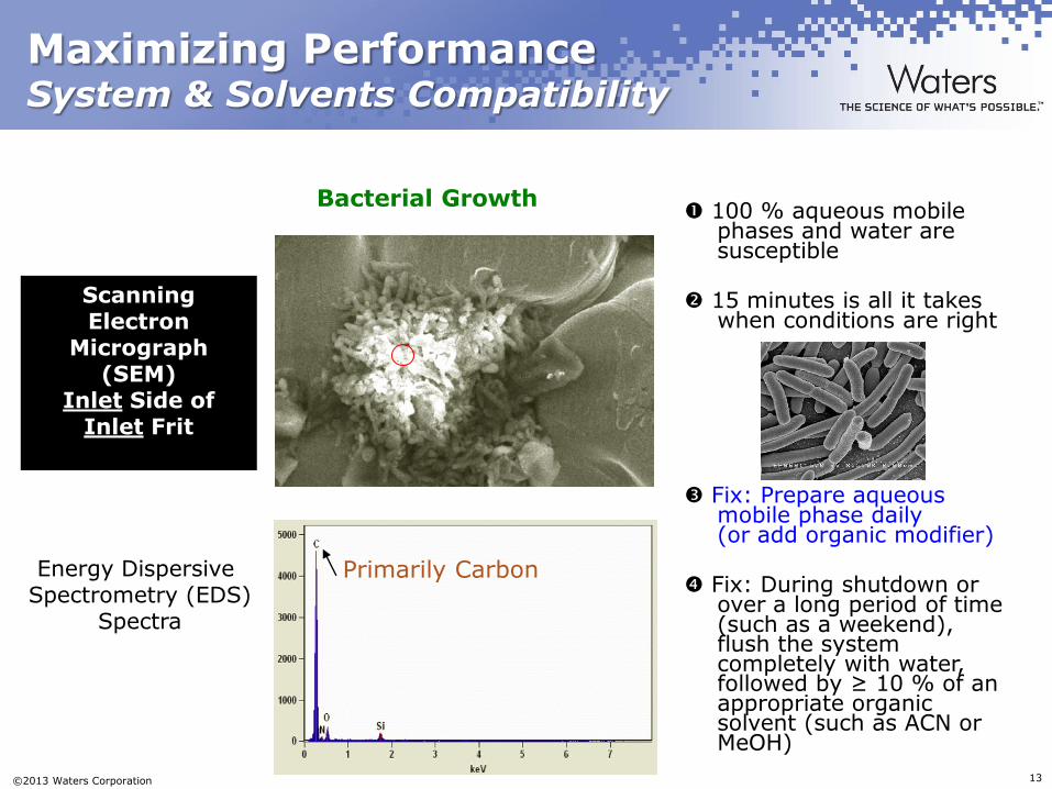
Scanning Electron
Micrograph (SEM)
Inlet Side of Inlet Frit
Energy Dispersive Spectrometry (EDS)
Spectra
100 % aqueous mobile phases and water are susceptible
15 minutes is all it takes
when conditions are right
Fix: Prepare aqueous mobile phase daily (or add organic modifier)
Fix: During shutdown or
over a long period of time (such as a weekend), flush the system completely with water, followed by ≥ 10 % of an appropriate organic solvent (such as ACN or MeOH)
Primarily Carbon
Bacterial Growth
Page 14
©2013 Waters Corporation 14
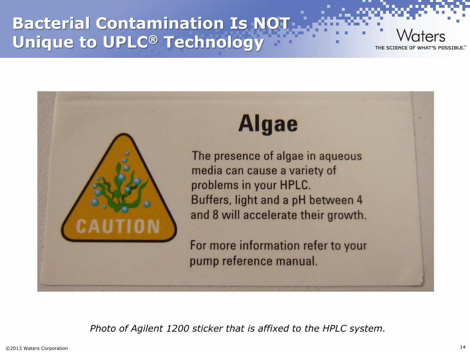
Bacterial Contamination Is NOT Unique to UPLC® Technology
Photo of Agilent 1200 sticker that is affixed to the HPLC system.
Page 15
©2013 Waters Corporation 15
Maximizing Performance
System & Solvents Compatibility
Bacterial growth is a very common source of UPLC® column plugging
Are you using a 100 % aqueous mobile phase? Using the system to mix isocratic mobile phase solvents?
– Prepare 100 % aqueous mobile phase daily
o Note: In-Line Filter may not get catch ALL bacteria
– Better solution:
o Gradient: add 5 % to 10 % organic modifier to aqueous mobile phase container and adjust gradient profile accordingly
o Isocratic: Pre-mix mobile phase solvents
Page 16
©2013 Waters Corporation 16
Maximizing Performance
System & Solvents Compatibility
Severe bacterial contamination?
–Remove and replace sinkers
o Bacteria are difficult to flush from sinkers
(and “Mission Impossible” from columns)
–Remove column, direct flow to waste
and flush system
–Flushing procedures described in
“Controlling Contamination in
UltraPerformance LC®/MS and
HPLC/MS Systems” (PN 715001307)
o e.g., ACN:MeOH:IPA:0.2 %
HCOOH in H2O (1:1:1:1)
Page 17
©2013 Waters Corporation 17
Maximizing Performance
System & Solvents Compatibility
Not Bacteria?
Important questions to ask at this point:
– Did these problems SUDDENLY occur? If so, what is different
now?
o Different UPLC method? Column? System change?
o Water system maintenance?
o Sample quality changed (e.g., NEW project/customer)
o Organic modifier batch/source?
– If always been this way, can method be run on different
system?
Page 18
©2013 Waters Corporation 18
Maximizing Performance
System & Solvents Compatibility
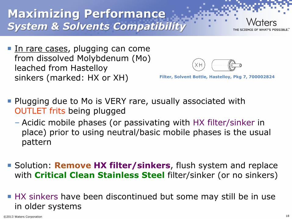
In rare cases, plugging can come from dissolved Molybdenum (Mo) leached from Hastelloy sinkers (marked: HX or XH)
Plugging due to Mo is VERY rare, usually associated with OUTLET frits being plugged
– Acidic mobile phases (or passivating with HX filter/sinker in place) prior to using neutral/basic mobile phases is the usual pattern
Solution: Remove HX filter/sinkers, flush system and replace with Critical Clean Stainless Steel filter/sinker (or no sinkers)
HX sinkers have been discontinued but some may still be in use in older systems
Filter, Solvent Bottle, Hastelloy, Pkg 7, 700002824
Page 19
©2013 Waters Corporation 19
Maximizing Performance
System & Solvents Compatibility
Root Cause: Hastelloy sinkers How:
• 16 % Mo in Hastelloy C-276 • In acidic and oxidizing solutions, Mo is leached from the HX sinkers • When switching mobile phase from acidic to neutral (or basic), dissolved molybdate may precipitate at a nucleation site such as column outlet frit
Interim Fix: Titanium sinkers Fix: “Critical Clean” SS sinkers
Energy Dispersive
Spectrometry (EDS)
Spectra
Filter, Solvent Bottle, Hastelloy, Pkg 7, 700002824
Solvent Filter, Titanium, Pkg 7, 700003530
Primarily Iron Chromium
Molybdenum
Scanning Electron
Micrograph (SEM)
BED Side of OUTLET Frit
Page 20
©2013 Waters Corporation 20
Maximizing Performance
System & Solvents Compatibility
Other sources of plugging
– Mobile phase filtration membrane dissolving
o Are you filtering your organic modifier prior to use? If so,
are you CERTAIN that it is compatible with the organic
modifier (e.g., polysulfone membranes are NOT compatible
with ACN)?
o SOLUTION: Avoid organic modifier filtration;
purchase pre-filtered (0.2 µm) solvents
• Recommended solvent brands (or their equivalents):
• J.T.Baker®: LC/MS Grade
• Burdick & Jackson: B&J Brand®
• Fisher: Optima® LC/MS Grade
Page 21
©2013 Waters Corporation 21
Maximizing Performance
System & Solvents Compatibility
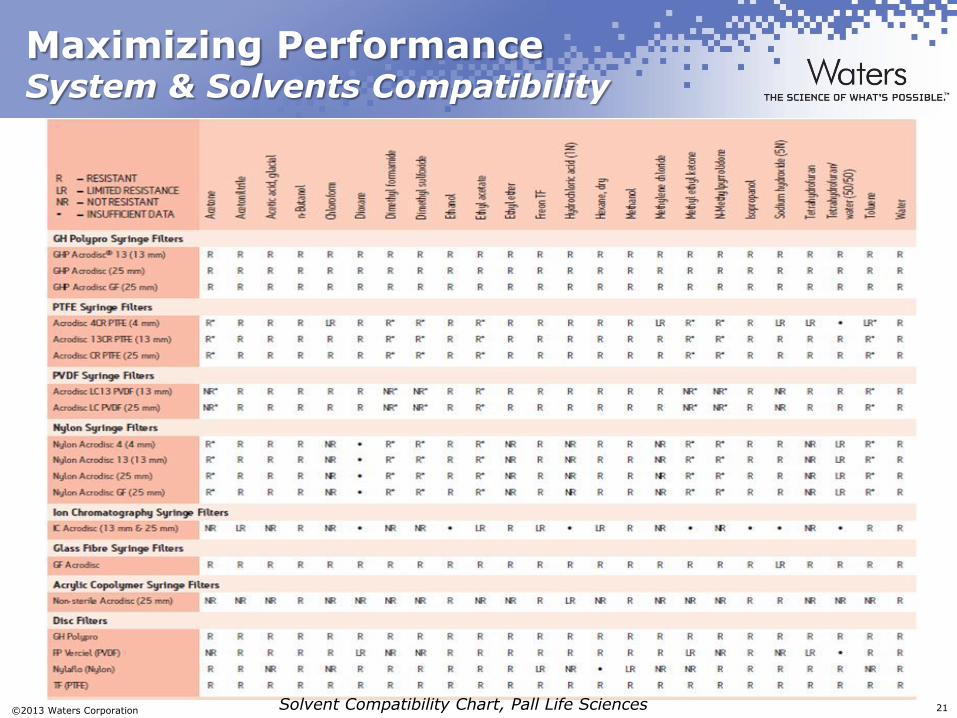
Solvent Compatibility Chart, Pall Life Sciences
Page 22
©2013 Waters Corporation 22
Maximizing Performance
System & Solvents Compatibility
Customer was filtering ACN through POLYSULFONE membrane
and complained of EXTREMELY short UPLC column lifetimes
Inlet Frit Plugged With
Dissolved Polysulfone Membrane Material
Page 23
©2013 Waters Corporation 23
Maximizing Performance
System & Solvents Compatibility – Filter Membrane Pore Size
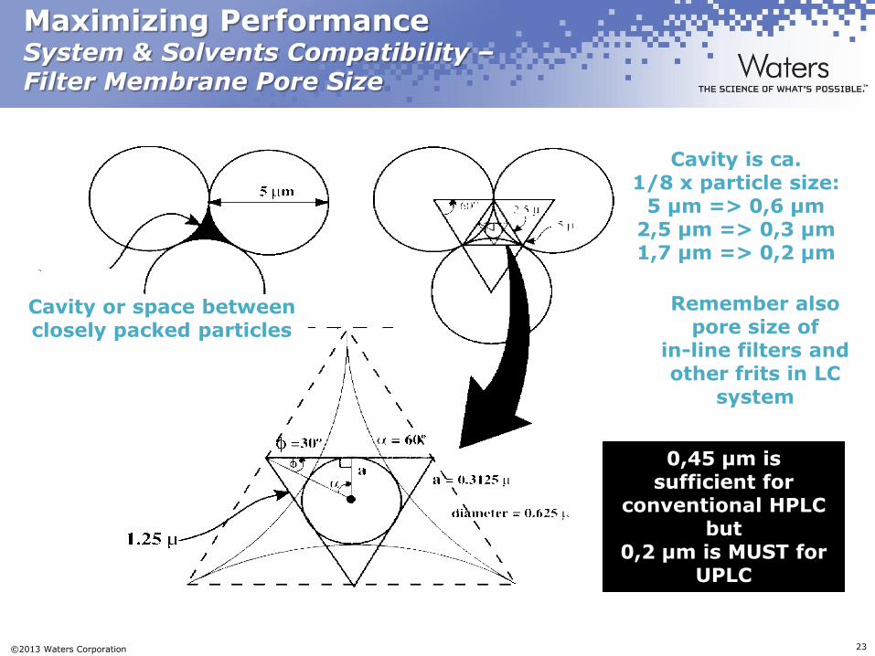
Cavity or space between closely packed particles
Cavity is ca. 1/8 x particle size:
5 µm => 0,6 µm 2,5 µm => 0,3 µm 1,7 µm => 0,2 µm
Remember also pore size of
in-line filters and other frits in LC
system
0,45 µm is sufficient for
conventional HPLC but
0,2 µm is MUST for UPLC
Page 24
©2013 Waters Corporation 24
Maximizing Performance
System & Solvents Compatibility
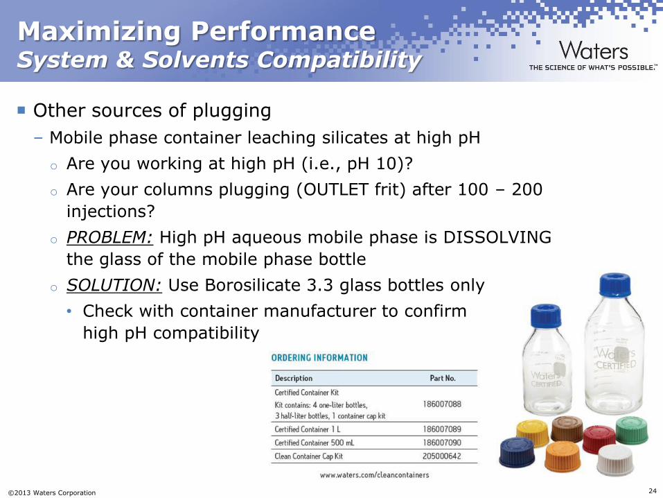
Other sources of plugging
– Mobile phase container leaching silicates at high pH
o Are you working at high pH (i.e., pH 10)?
o Are your columns plugging (OUTLET frit) after 100 – 200
injections?
o PROBLEM: High pH aqueous mobile phase is DISSOLVING
the glass of the mobile phase bottle
o SOLUTION: Use Borosilicate 3.3 glass bottles only
• Check with container manufacturer to confirm
high pH compatibility
Page 25
©2013 Waters Corporation 25
Maximizing Performance
System & Solvents Compatibility
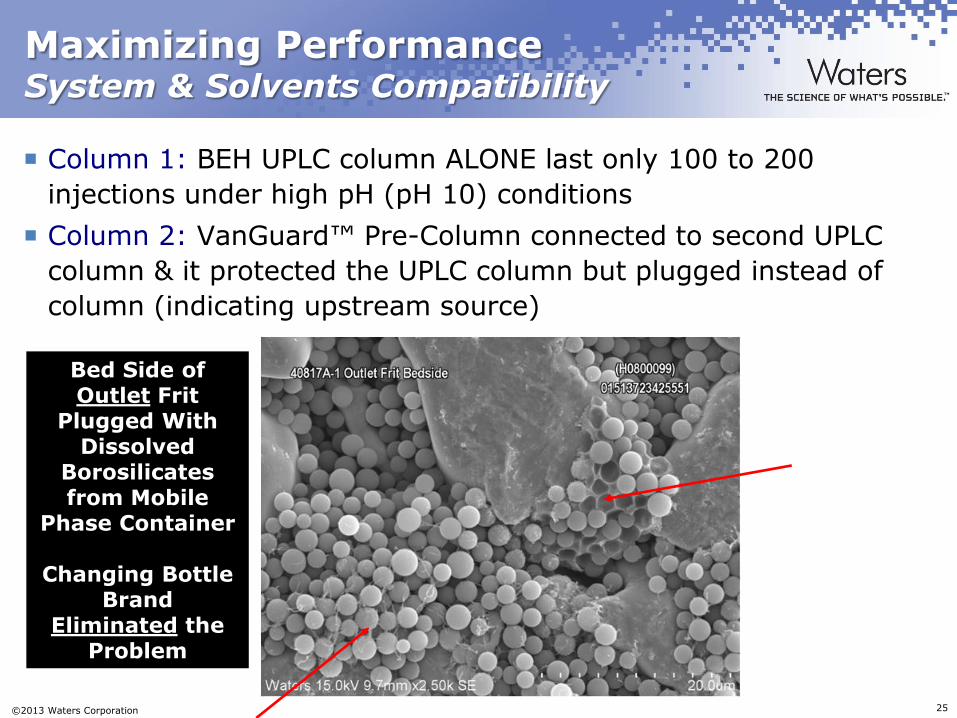
Column 1: BEH UPLC column ALONE last only 100 to 200
injections under high pH (pH 10) conditions
Column 2: VanGuard™ Pre-Column connected to second UPLC
column & it protected the UPLC column but plugged instead of
column (indicating upstream source)
Bed Side of Outlet Frit
Plugged With Dissolved
Borosilicates from Mobile
Phase Container
Changing Bottle Brand
Eliminated the Problem
Page 26
©2013 Waters Corporation 26
Maximizing Performance
System & Solvents Compatibility
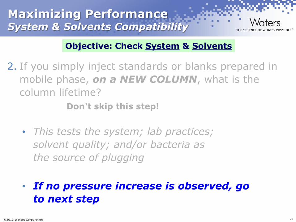
2. If you simply inject standards or blanks prepared in
mobile phase, on a NEW COLUMN, what is the
column lifetime?
Don't skip this step!
• This tests the system; lab practices;
solvent quality; and/or bacteria as
the source of plugging
• If no pressure increase is observed, go
to next step
Objective: Check System & Solvents
Page 27
©2013 Waters Corporation 27
Maximizing Performance
Sample Preparation Compatibility
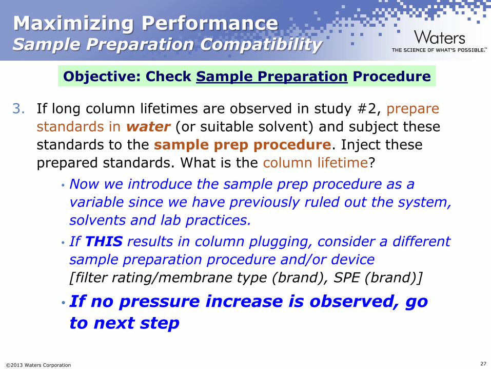
3. If long column lifetimes are observed in study #2, prepare
standards in water (or suitable solvent) and subject these
standards to the sample prep procedure. Inject these
prepared standards. What is the column lifetime?
• Now we introduce the sample prep procedure as a
variable since we have previously ruled out the system,
solvents and lab practices.
• If THIS results in column plugging, consider a different
sample preparation procedure and/or device
[filter rating/membrane type (brand), SPE (brand)]
• If no pressure increase is observed, go
to next step
Objective: Check Sample Preparation Procedure
Page 28
©2013 Waters Corporation 28
Maximizing Performance Sample Matrix
4. All that is left now is the sample matrix. The
system, solvents, lab practices and sample
preparation device/process have been eliminated. If
you inject samples onto a clean, bacteria-free
UPLC® system/column and plugging or short
column lifetimes are now encountered, the sample
quality & preparation need to be investigated.
Objective: Check Samples (Matrix)
Page 29
©2013 Waters Corporation 29
Maximizing Performance Sample Matrix
• By process of elimination, the sample matrix MUST be source of UPLC® column failure • What are the samples & matrix? Have the
samples/quality changed recently? Preparation procedure? Filtration details? Centrifugation? How long? RPMs?
• Are VanGuard™ Pre-Columns being used? In-Line Filter unit? Do THEY plug instead of UPLC column?
• Consult with your Waters Chemistry Business Unit (CBU) Specialist to determine sample preparation options and solutions (e.g., Oasis®, Ostro™, Sirocco™ etc.) which will prolong UPLC® column lifetime and provide more reliable results
Objective: Check Samples (Matrix)
Page 30
©2013 Waters Corporation 30
Maximizing Performance Sample Matrix: VanGuard™ Pre-columns
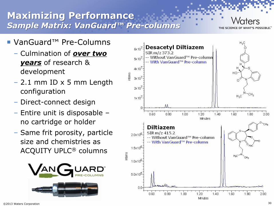
VanGuard™ Pre-Columns
– Culmination of over two
years of research &
development
– 2.1 mm ID x 5 mm Length
configuration
– Direct-connect design
– Entire unit is disposable –
no cartridge or holder
– Same frit porosity, particle
size and chemistries as
ACQUITY UPLC® columns
Page 31
©2013 Waters Corporation 31
Agenda
Introduction
Techniques for Maximizing UPLC® Column Lifetimes
Conclusion
Appendix
Page 32
©2013 Waters Corporation 32
Maximizing Performance Conclusion
> 99 % of UPLC® columns are used without issue
To realize HUGE potential of UPLC® Technology,
small procedural changes may be required
–Analogous to past technology changes required to
utilize 3 µm particle or microbore LC columns
–Previous HPLC method success does NOT guarantee
future UPLC method success
Most customers realize thousands of injections per
UPLC® column right out of the box
– Maximizing UPLC® column lifetimes can be realized in an
efficient, systematic and logical way – Waters can help in this!
Page 33
©2013 Waters Corporation 33
Agenda
Introduction
Techniques for Maximizing UPLC® Column Lifetimes
Conclusion
Appendix
Page 34
©2013 Waters Corporation 34
Prequel to Maximizing Performance Procedure
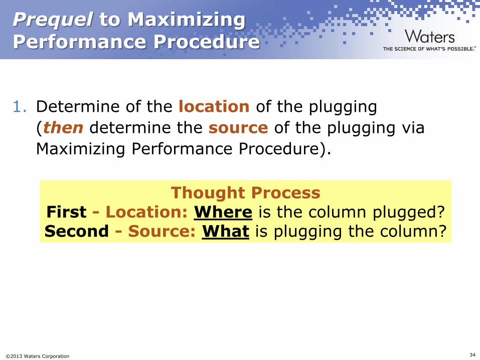
1. Determine of the location of the plugging
(then determine the source of the plugging via
Maximizing Performance Procedure).
Thought Process First - Location: Where is the column plugged? Second - Source: What is plugging the column?
Page 35
©2013 Waters Corporation 35
Prequel to Maximizing Performance Procedure
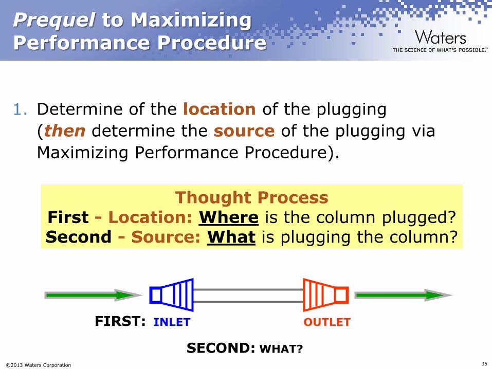
1. Determine of the location of the plugging
(then determine the source of the plugging via
Maximizing Performance Procedure).
Thought Process First - Location: Where is the column plugged? Second - Source: What is plugging the column?
FIRST: INLET OUTLET
SECOND: WHAT?
Page 36
©2013 Waters Corporation 36
Prequel to Maximizing Performance Procedure
2. Change the Inlet frit in order to determine the
location of the plugging*.
• Columns are acting like fine filters. Change
the Inlet frit.
• If this does not eliminate column plugging,
change the Outlet frit via the same procedure.
The remaining steps are (fairly) easy.
(*) – ACQUITY UPLC® Columns Inlet Frit
Replacement Procedure
Page 37
©2013 Waters Corporation 37
Inlet Frit Replacement Introduction
ACQUITY UPLC® Columns Frit Replacement Procedure
– Simple, yet valuable procedure designed to find LOCATION
(not source) of column plugging
– Demonstrates that the PACKED bed is not the problem
– Simple and takes only a couple of minutes
– No special items/tools needed
– CUSTOMER & Waters representative should perform this
operation together in CUSTOMER laboratory
Page 38
©2013 Waters Corporation 38
Inlet Frit Replacement Definition
ACQUITY UPLC® Columns Frit Replacement Procedure
–An investigative procedure: NOT a means to
prolong column lifetime
–An investigative procedure: SHOULD NOT be
required on a regular basis (something is wrong if
this NEEDS to be done often in order to alleviate
column pressure)
Page 39
©2013 Waters Corporation 39
Inlet Frit Replacement Before You Start
Safety First
–Safety glasses, gloves and lab coat are recommended prior to beginning this procedure
–Consider performing procedure in laboratory fume hood
–Confirm with UPLC® column user the types and quality of samples injected onto column
–Do not open the column if you feel uncomfortable doing so because of type of samples injected (e.g., radioactivity, infectious diseases etc.)
Page 40
©2013 Waters Corporation 40
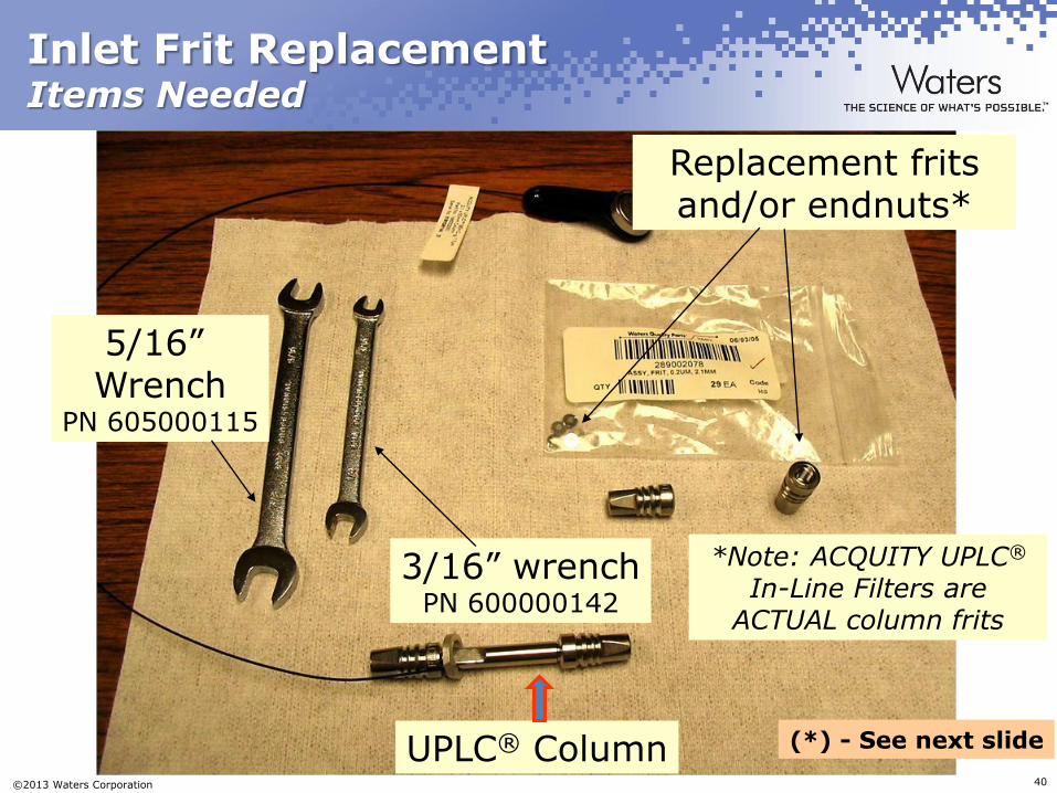
Inlet Frit Replacement Items Needed
3/16” wrench PN 600000142
5/16” Wrench
PN 605000115
UPLC® Column
Replacement frits and/or endnuts*
*Note: ACQUITY UPLC® In-Line Filters are
ACTUAL column frits
(*) - See next slide
Page 41
©2013 Waters Corporation 41
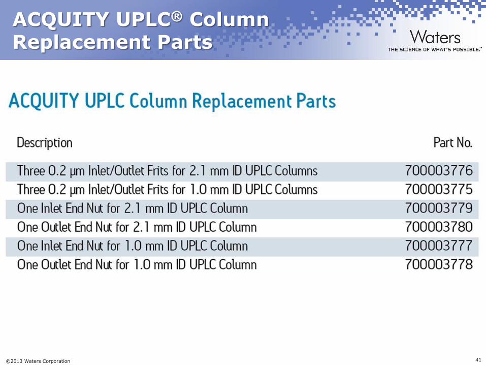
ACQUITY UPLC® Column Replacement Parts
Page 42
©2013 Waters Corporation 42
Inlet Frit Replacement Overview
1. Remove Inlet nut (end fitting). The frit will be inside nut.
2. Remove frit from nut (end fitting) {if necessary, turn nut upside down and tap on flat surface to dislodge frit from inside the inlet nut}.
3. Inspect the column sealing surface for excess material that may have escaped as the nut is removed.
4. Wipe the sealing surface of the column, do not disturb the exposed packed bed (and observe if bed is discolored or voided).
Page 43
©2013 Waters Corporation 43
Inlet Frit Replacement Overview (cont.)
5) Place new frit inside nut.
6) Hand-tighten the assembled frit/nut onto the
column.
7) Torque inlet nut to column at approximately
1/2 turn past hand tightened.
Page 44
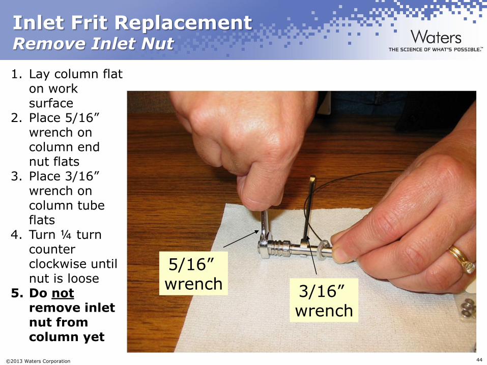
©2013 Waters Corporation 44
Inlet Frit Replacement Remove Inlet Nut
1. Lay column flat on work surface
2. Place 5/16” wrench on column end nut flats
3. Place 3/16” wrench on column tube flats
4. Turn ¼ turn counter clockwise until nut is loose
5. Do not remove inlet nut from column yet
5/16” wrench 3/16”
wrench
Page 45
©2013 Waters Corporation 45
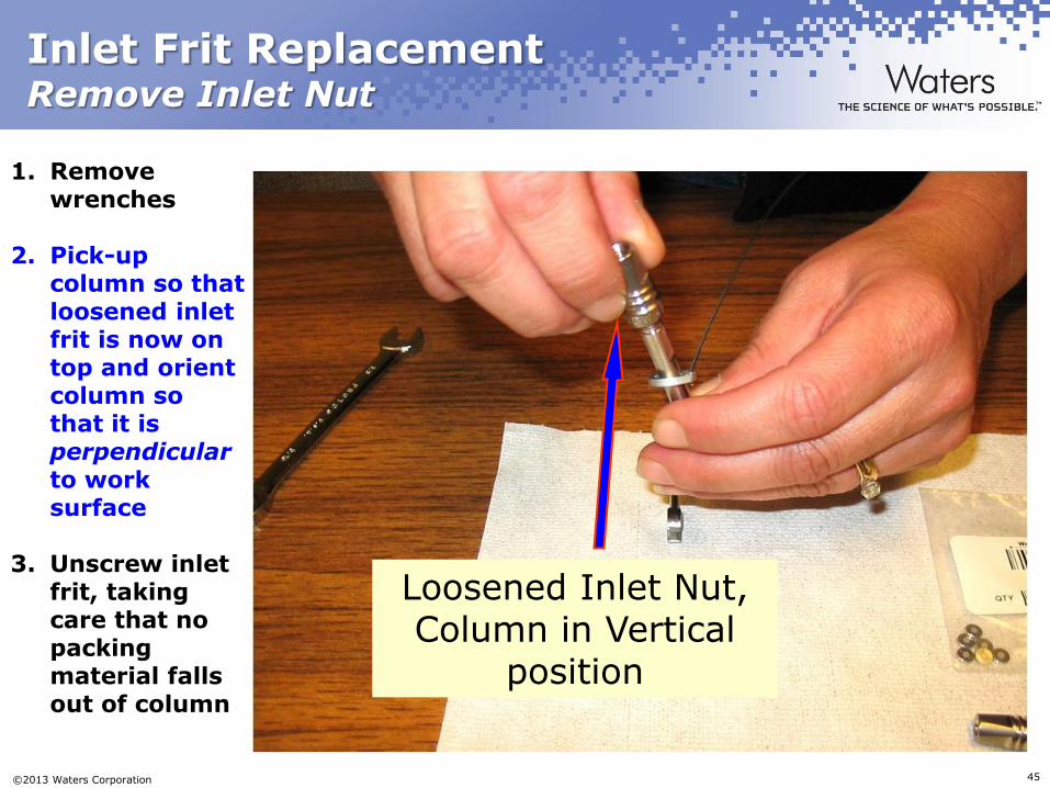
Inlet Frit Replacement Remove Inlet Nut
Loosened Inlet Nut, Column in Vertical
position
1. Remove wrenches
2. Pick-up column so that loosened inlet frit is now on top and orient column so that it is perpendicular to work surface
3. Unscrew inlet frit, taking care that no packing material falls out of column
Page 46
©2013 Waters Corporation 46
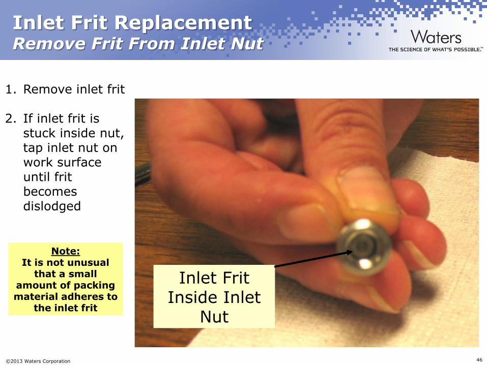
Inlet Frit Replacement Remove Frit From Inlet Nut
1. Remove inlet frit
2. If inlet frit is stuck inside nut, tap inlet nut on work surface until frit becomes dislodged
Inlet Frit Inside Inlet
Nut
Note: It is not unusual
that a small amount of packing material adheres to
the inlet frit
Page 47
©2013 Waters Corporation 47
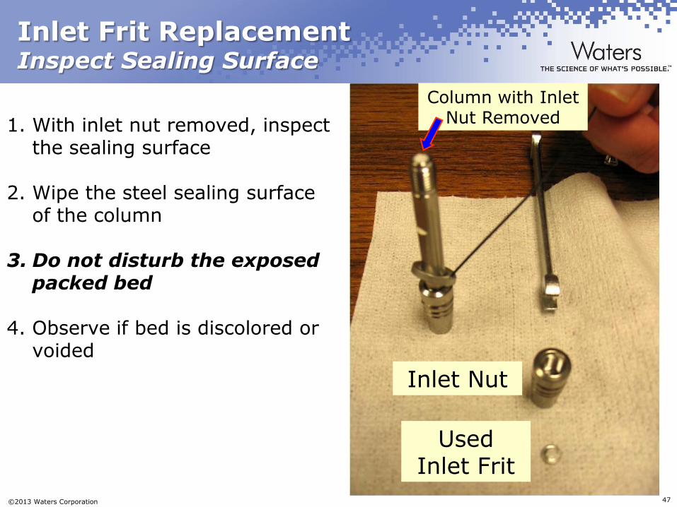
Inlet Frit Replacement Inspect Sealing Surface
Used Inlet Frit
Inlet Nut
Column with Inlet Nut Removed 1. With inlet nut removed, inspect
the sealing surface
2. Wipe the steel sealing surface of the column
3. Do not disturb the exposed packed bed
4. Observe if bed is discolored or voided
Page 48
©2013 Waters Corporation 48
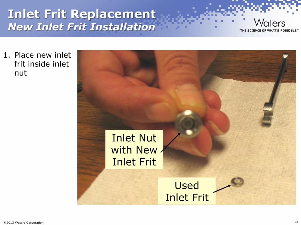
Inlet Frit Replacement New Inlet Frit Installation
1. Place new inlet frit inside inlet nut
Inlet Nut with New Inlet Frit
Used Inlet Frit
Page 49
©2013 Waters Corporation 49
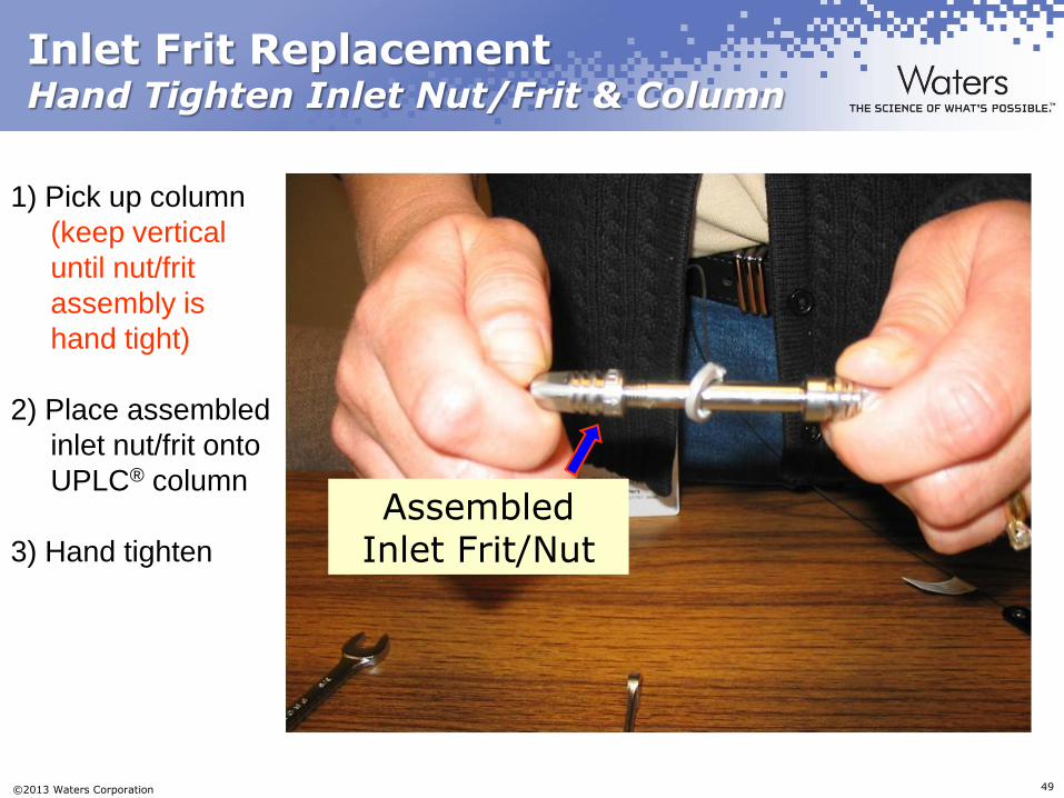
Inlet Frit Replacement Hand Tighten Inlet Nut/Frit & Column
1) Pick up column
(keep vertical
until nut/frit
assembly is
hand tight)
2) Place assembled
inlet nut/frit onto
UPLC® column
3) Hand tighten
Assembled Inlet Frit/Nut
Page 50
©2013 Waters Corporation 50
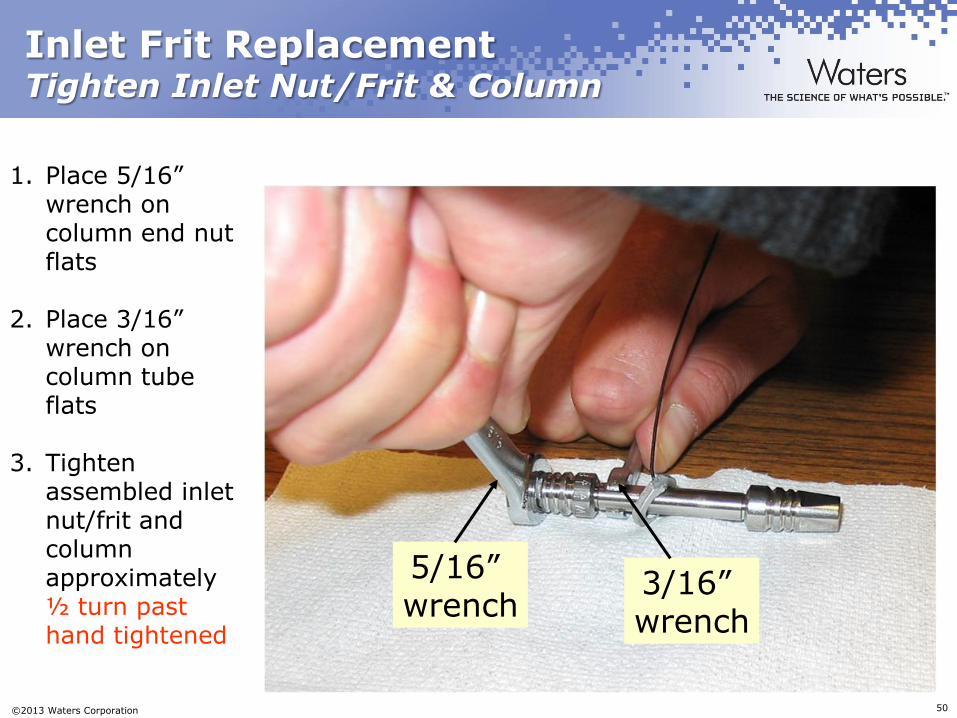
Inlet Frit Replacement Tighten Inlet Nut/Frit & Column
1. Place 5/16” wrench on column end nut flats
2. Place 3/16” wrench on column tube flats
3. Tighten assembled inlet nut/frit and column approximately ½ turn past hand tightened
5/16” wrench
3/16” wrench
Page 51
©2013 Waters Corporation 51
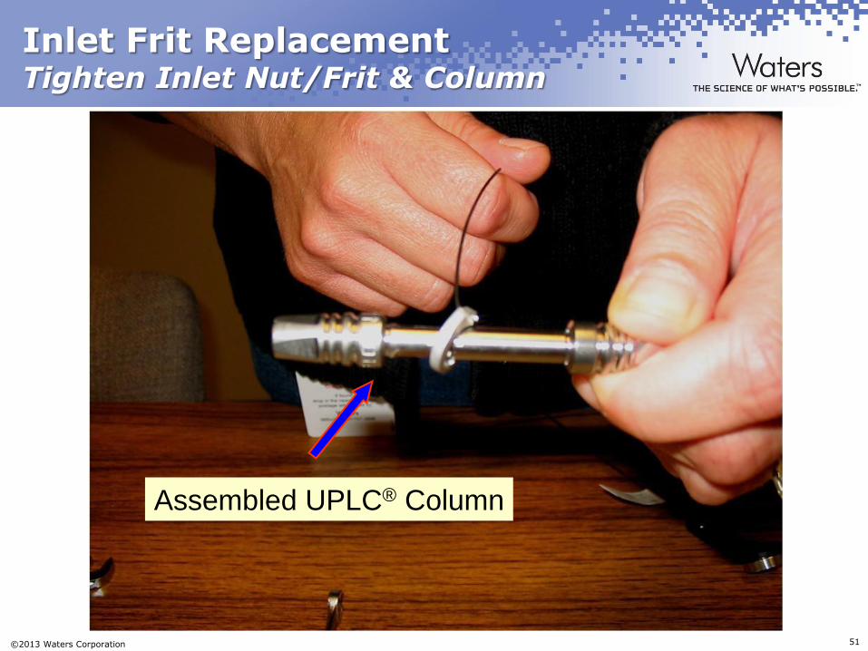
Inlet Frit Replacement Tighten Inlet Nut/Frit & Column
Assembled UPLC® Column
Page 52
©2013 Waters Corporation 52
Inlet Frit Replacement Overview (cont.)
5) Place new frit (from PN 205000343 or PN 700002775) inside nut.
6) Hand-tighten the assembled frit/nut onto the column.
7) Torque inlet nut to column at approximately
1/2 turn past hand tightened.
8) Re-Check column for lower back pressure.
Page 53
©2013 Waters Corporation 53
Inlet Frit Replacement Procedure Conclusions
Procedure designed to determine the LOCATION of UPLC®
column plugging
– It is not designed to prolong UPLC® column lifetimes
(although it CAN)
– It should not be necessary to perform this procedure on a
regular basis
If INLET frit is not the LOCATION of the plugging,
change OUTLET frit using the same procedure
Use THIS column for UPLC Maximizing
Performance Procedure
Page 54
©2013 Waters Corporation 54


![ACQUITY UPLC Peptide BEH C18, 130Å and 300Å … · 2 [ CARE AND USE MANUAL ] ACQUITY UPLC Peptide BEH C18, 130Å and 300Å Columns II. GETTING STARTED Each Peptide Separation Technology](https://static.documents.pub/doc/80x56/5b76f36d7f8b9ad2498bbbf3/acquity-uplc-peptide-beh-c18-130a-and-300a-2-care-and-use-manual-acquity.jpg)


