92
ACQUITY UPLC System Quick Start Guide 71500082503/ Revision C Copyright © Waters Corporation 2006. All rights reserved.

ACQUITY UPLC System Quick Start Guide
71500082503/ Revision C
Copyright © Waters Corporation 2006.All rights reserved.
Copyright notice
© 2004−06 WATERS CORPORATION. PRINTED IN THE UNITED STATES OF AMERICA AND IRELAND. ALL RIGHTS RESERVED. THIS DOCUMENT OR PARTS THEREOF MAY NOT BE REPRODUCED IN ANY FORM WITHOUT THE WRITTEN PERMISSION OF THE PUBLISHER.
The information in this document is subject to change without notice and should not be construed as a commitment by Waters Corporation. Waters Corporation assumes no responsibility for any errors that may appear in this document. This document is believed to be complete and accurate at the time of publication. In no event shall Waters Corporation be liable for incidental or consequential damages in connection with, or arising from, its use.
Waters Corporation34 Maple StreetMilford, MA 01757USA
TrademarksMillennium and Waters are registered trademarks, and ACQUITY UPLC, eCord, Empower, MassLynx, and nanoACQUITY UPLC are trademarks of Waters Corporation.
PharMed is a registered trademark of Saint-Gobain Ceramics & Plastics, Inc.
Windows is a registered trademark of Microsoft Corporation.
Other trademarks or registered trademarks are the sole property of their respective owners.

Customer commentsWaters’ Technical Communications department invites you to tell us of any errors you encounter in this document or to suggest ideas for otherwise improving it. Please help us better understand what you expect from our documentation so that we can continuously improve its accuracy and usability.
We seriously consider every customer comment we receive. You can reach us at [email protected].
Waters Corporation34 Maple StreetMilford, MA 01757USA
iii

Safety considerations
Some reagents and samples used with Waters® instruments can pose chemical, biological, and radiological hazards. Be sure you are aware of the potentially hazardous effects of all substances you work with. Always observe Good Laboratory Practice (GLP) guidelines, published by the U.S. Food and Drug Administration, and consult your organization’s safety representative for guidance.
When you develop methods, follow the “Protocol for the Adoption of Analytical Methods in the Clinical Chemistry Laboratory,” American Journal of Medical Technology, 44, 1, pages 30–37 (1978). This protocol addresses good operating procedures and the techniques necessary to validate system and method performance.
Safety advisoriesConsult Appendix A in the ACQUITY UPLC System Operator’s Guide for a comprehensive list of warning and caution advisories.
Operating the ACQUITY UPLC system
When operating the ACQUITY UPLC system, follow standard quality control procedures and the guidelines presented in this section.
iv
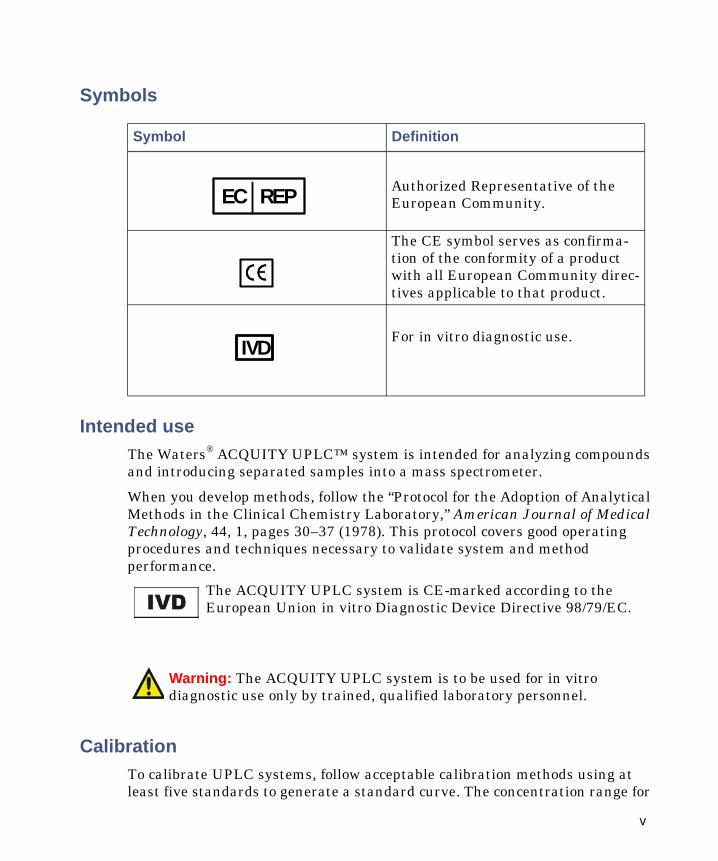
Symbols
Intended useThe Waters® ACQUITY UPLC™ system is intended for analyzing compounds and introducing separated samples into a mass spectrometer.
When you develop methods, follow the “Protocol for the Adoption of Analytical Methods in the Clinical Chemistry Laboratory,” American Journal of Medical Technology, 44, 1, pages 30–37 (1978). This protocol covers good operating procedures and techniques necessary to validate system and method performance.
CalibrationTo calibrate UPLC systems, follow acceptable calibration methods using at least five standards to generate a standard curve. The concentration range for
Symbol Definition
Authorized Representative of the European Community.
The CE symbol serves as confirma-tion of the conformity of a product with all European Community direc-tives applicable to that product.
For in vitro diagnostic use.
The ACQUITY UPLC system is CE-marked according to the European Union in vitro Diagnostic Device Directive 98/79/EC.
Warning: The ACQUITY UPLC system is to be used for in vitro diagnostic use only by trained, qualified laboratory personnel.
EC REP
IVD
v
standards should cover the entire range of quality-control samples, typical specimens, and atypical specimens.
To calibrate mass spectrometers, consult the calibration section of the operator’s guide of the instrument you are calibrating.
Quality controlRoutinely run three quality-control samples that represent subnormal, normal, and above-normal levels of a compound. Ensure that quality-control sample results fall within an acceptable range, and evaluate precision from day to day and run to run. Data collected when quality control samples are out of range might not be valid. Do not report these data until you are certain that the instrument performs satisfactorily.
When analyzing samples from a complex matrix such as soil, tissue, serum/plasma, whole blood, etc., note that the matrix components can adversely affect LC/MS results, enhancing or suppressing ionization. To minimize these matrix effects, Waters recommends you adopt the following measures:
• Prior to the instrumental analysis, use appropriate sample pretreatment such as protein precipitation, liquid/liquid extraction (LLE), or solid phase extraction (SPE) to remove matrix interferences.
• Whenever possible, verify method accuracy and precision using matrix-matched calibrators and QC samples.
• Use one or more internal standard compounds, preferably isotopically-labeled analytes.
vi

IVD authorized representative information
IVD authorized representative
Waters Corporation (Micromass UK Limited) is registered in the United Kingdom with the Medicines and Healthcare Products Regulatory Agency (MHRA) at Market Towers, 1 Nine Elms Lane, London, SW8 5NQ. The reference number is IVD000167.
Waters Corporation (Micromass UK Ltd.)
Floats RoadWythenshaweManchester M23 9LZUnited Kingdom
Telephone: +44-161-946-2400
Fax: +44-161-946-2480
Contact: Quality manager
vii

viii

Table of Contents
Safety considerations .......................................................................................... iv Safety advisories ................................................................................................. iv
Operating the ACQUITY UPLC system ........................................................... iv Symbols ................................................................................................................ v Intended use......................................................................................................... v Calibration ........................................................................................................... v Quality control .................................................................................................... vi
IVD authorized representative information ................................................ vii IVD authorized representative ........................................................................ vii
1 System Overview .................................................................................... 1-1
Instruments, components, and data systems ............................................. 1-2
Binary solvent manager .................................................................................. 1-4 How the binary solvent manager works......................................................... 1-5
Sample manager ................................................................................................ 1-6 How sample flows ............................................................................................ 1-6
Column heater ................................................................................................... 1-7
Optional sample organizer ............................................................................. 1-8
Optical detectors ............................................................................................... 1-9 TUV detector .................................................................................................... 1-9 PDA detector .................................................................................................... 1-9 ELS detector..................................................................................................... 1-9 Median baseline filter.................................................................................... 1-10
Data systems .................................................................................................... 1-10 Empower software ......................................................................................... 1-10 MassLynx software ........................................................................................ 1-10
Columns ............................................................................................................. 1-11 eCord column chip ......................................................................................... 1-11
Table of Contents ix

FlexCart ............................................................................................................. 1-12
For more information .................................................................................... 1-12
2 Preparing System Hardware ............................................................... 2-1
Powering-on the system .................................................................................. 2-2
Monitoring startup tests ................................................................................. 2-2
Monitoring system instrument LEDs ........................................................... 2-3 Power LED ....................................................................................................... 2-3 Status LEDs ..................................................................................................... 2-3
Preparing the binary solvent manager ....................................................... 2-5 Performing a seal wash prime ........................................................................ 2-5 Priming the binary solvent manager .............................................................. 2-8 Priming a dry binary solvent manager........................................................... 2-8 Priming a wetted binary solvent manager ................................................... 2-10
Preparing the sample manager ................................................................... 2-14 Selecting weak wash and strong wash solvents........................................... 2-14 Priming the sample manager........................................................................ 2-16 Washing the sample manager needle ........................................................... 2-18 Characterizing the needle seal...................................................................... 2-20 Characterizing the needle and sample loop volumes................................... 2-21 Loading sample plates in the sample manager............................................ 2-22 Selecting the optimum sample injection mode............................................. 2-23 Installing the sample manager shade .......................................................... 2-27
Preparing the sample organizer ................................................................. 2-29 Initiating communications ............................................................................ 2-29 Loading sample plates ................................................................................... 2-30 Displaying sample plate information ........................................................... 2-34
Preparing the detector .................................................................................. 2-35 Preparing the TUV detector .......................................................................... 2-35
Conditioning the column .............................................................................. 2-38
Shutting down the system ............................................................................ 2-39 Between analyses........................................................................................... 2-39
x Table of Contents

Shutting down for fewer than 72 hours........................................................ 2-40 Shutting down for more than 72 hours......................................................... 2-40
3 Configuring System Software ............................................................. 3-1
Configuring Empower ..................................................................................... 3-2 Starting Empower and logging in ................................................................... 3-2 Selecting system instruments ......................................................................... 3-2 About the binary solvent manager control panel........................................... 3-4 About the sample manager control panel....................................................... 3-7 About the TUV detector control panel ............................................................ 3-9
Starting the ACQUITY UPLC Console from Empower .......................... 3-11
Configuring MassLynx software ................................................................. 3-12
Starting the ACQUITY UPLC Console from MassLynx software ........ 3-13
4 Verifying System Operation ................................................................ 4-1
Preparing the system ....................................................................................... 4-2
Creating the test methods ............................................................................... 4-5 Creating the instrument method .................................................................... 4-5 Creating the sample set method ..................................................................... 4-8
Performing the gradient performance test ................................................ 4-9
Table of Contents xi

xii Table of Contents

1 System Overview
This section describes the components and features of the ACQUITY UPLC™ system.
Contents:
Topic Page
Instruments, components, and data systems 1-2
Binary solvent manager 1-4
Sample manager 1-6
Column heater 1-7
Optional sample organizer 1-8
Optical detectors 1-9
Data systems 1-10
Columns 1-11
FlexCart 1-12
For more information 1-12
1-1

Instruments, components, and data systems
ACQUITY UPLC systems include a binary solvent manager, sample manager, column heater, detectors (tunable ultraviolet, photodiode array, or evaporative light scattering), and a specialized ACQUITY UPLC column.
Small-particle chemistries as utilized in UPLC system chromatography generate narrow peaks. To maintain these narrow peaks, extra bandspreading must be controlled by lower detector cell volume, minimized tubing volumes, and specialized fittings. Narrow peak widths can sometimes require higher data rates. The TUV, PDA, and ELS detectors can sample up to 80 data points per second.
The binary solvent manager and injector can produce pressures up to 103421 kPa (1034 bar, 15000 psi) and can generate high-pressure gradients with minimal gradient delay. The upper limit of the flow rate range is 2 mL/min.
The sample manager can accommodate two plates in a microtiter plate format or 2-mL vials in full-height plate format. An optional sample organizer increases the capacity of the system to as many as 22 microtiter plates (21 in the sample organizer and one in the sample manager), or eight vial racks (seven in the sample organizer and one in the sample manager).
Waters® Empower™ chromatography software or MassLynx™ mass spectrometry software controls the systems.
1-2 System Overview
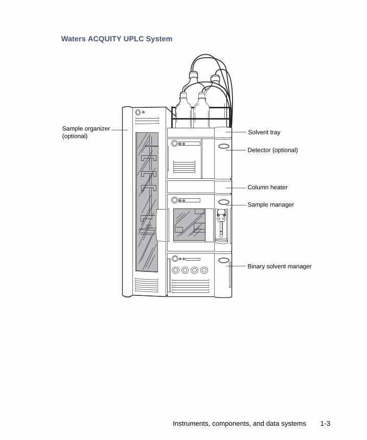
Waters ACQUITY UPLC System
Solvent tray
Detector (optional)
Column heater
Sample manager
Binary solvent manager
Sample organizer (optional)
Instruments, components, and data systems 1-3
Binary solvent manager
The binary solvent manager is a high-pressure pump that moves solvent through the system. It provides steady (pulse-free) solvent flow at analytical flow rates. The binary solvent manager delivers solvent at flow rates of 1 mL/min at 103421 kPa (1034 bar, 15000 psi) and up to 2 mL/min at reduced pressures to 62053 kPa (621 bar, 9000 psi). The solvent manager can pump two solvents simultaneously.
1-4 System Overview
How the binary solvent manager worksEach of the solvent manager’s two independent pump systems, A (left) and B (right), contains two linear-drive actuators (left and right). Each left and right actuator pair comprises a single reciprocating “serial” pump that delivers precise flow of a single solvent. The two pump systems combine their two solvents at a filter/tee mixer. From there, the solvent mixture flows to the sample manager.
The chromatography software controls the two solvents’ mixing ratio by varying the flow of pump A relative to that of pump B. A pressure transducer in each pump head relays pressure data to the solvent manager, whose firmware measures pump head pressures during the pumping cycle. Thus the solvent manager independently pre-compresses the solvents in both the A and B portions to ensure consistent solvent delivery and minimize pump-induced detector baseline disturbances.
Binary solvent manager 1-5

Sample manager
The ACQUITY UPLC sample manager injects the samples it draws from microtiter plates or vials into the chromatographic flow stream. A locating mechanism uses a probe to access sample locations and draw sample from them. In the needle overfill load-ahead mode, the sample manager can perform an injection in approximately 15 seconds. The first injection requires additional overhead time.
The sample manager accepts standard footprint plates, 5.03 ±0.02 inch × 3.365 ±0.02 inch, that conform to ANSI standards (maximum height = 2.2 inches, including covers). You may program any combination of these plates and vial holders for automated sample processing. Samples are loaded into the sample manager via the front door or the optional sample organizer, which transfers samples back and forth between the two instruments. The sample manager can maintain samples at any temperature between 4º to 40º C (39.2º to 104º F) in 25º C (77º F) or less ambient conditions.
How sample flowsWhen the default mode, partial loop with needle overfill, is requested, the sample manager needle carriage moves to the specified well location and draws in an air gap. A stainless steel puncture needle pierces the well cover and lowers into the well. The sample needle emerges from within the puncture needle and protrudes into the sample, and draws in a sample volume equal to the specified injection volume plus 3.0 µL (2.0 µL pre-sample volume and 1.0 µL post-sample volume). The sample syringe continues to pull the sample aliquot through the sample needle and through the injection valve until the pre-sample and sample injection volume passes through the injection valve. The valve actuates, switching the sample loop to the load position. The sample is pushed back toward the needle and the sample volume is then pushed into the sample loop. The sample loop moves to the injection position and the sample is carried by the pump to the column.
1-6 System Overview

Column heater 1-7
Column heater
The column heater is of a modular design and its footprint is identical to that of the sample manager. Thus it attaches to the top of the sample manager and serves as that instrument’s top cover. The column heater’s front compartment can accommodate any Waters column up to 4.6 mm ID and 150 mm long. The column rests in a U-shaped tray that swivels outward to receive the column from either side.
To reduce dispersion associated with dead volume and minimize the length of tubing between system instruments, the column tray swings outward to any position between 0° and 180°. In the 0°, “home”, position, the column tray is directly above the sample manager and connected to the optical detector (on top of the column heater). In the 180°, “away”, position, the column heater can be plumbed into a mass spectrometer (located on the system’s right).
The column heater heats the column compartment to any temperature from 5º C (9º F) above ambient to 65º C (149º F). A film element insulated to minimize power consumption and facilitate thermal stability is attached to the tray and produces heat. A passive column stabilizer, inside the tray, reduces sensitivity to ambient temperature swings and minimizes bandspreading.
A receptacle on the column heater’s right side receives the column's eCord™ chip. The eCord column chip stores column information which can be accessed from the ACQUITY UPLC Console.
The column heater drip tray captures any leakage, routing it to the sample manager via a drip tube.
Optional sample organizer
The optional sample organizer stores microtiter or vial plates and transfers them to and from the sample manager, automating their processing and increasing throughput.
The sample organizer’s storage shelf compartment can hold a selection of ANSI plates. Sample plates are loaded into the organizer through a large, swing-open front door. The shelf compartment is thermally conditioned by sample organizer heater/coolers that, together with the sample manager heater/cooler, control the temperature between 4º and 40º C (39.2º and 104º F) in 25º C (77º F) or less ambient conditions.
Three subassemblies move plates within the sample organizer: the Z-Drive, the sample organizer transfer shuttle (Y-axis), and the sample manager transfer shuttle (X-axis). The Z-Drive moves the Y-axis to the target shelf, where the Y-axis picks the plate. Then the Z-Drive moves the Y-axis to the same elevation as the X-axis. The Y-axis shuttles the plate into the X-axis, which transfers the plate into the sample manager for processing. When the sample manager finishes with the plate, the Y-axis pulls it back into the sample organizer. The process is reversed to return the plate to the shelf it came from.
1-8 System Overview
Optical detectors
The system can be configured with an TUV, PDA, or ELS optical detector or any combination of the three.
TUV detectorThe TUV (tunable ultraviolet) optical detector is a two-channel, ultraviolet/visible (UV/Vis) absorbance detector designed for use in the ACQUITY UPLC system. The detector, controlled by Empower software for LC applications or MassLynx software for LC/MS applications, operates as an integral part of the system.
The detector offers two flow cell options. The analytical flow cell, with a volume of 500 nanoliters and a pathlength of 10 mm, and the high sensitivity flow cell, with a volume of 2.4 microliters and a 25 mm pathlength, both utilize the Waters patented light-guiding flow cell technology.
The TUV detector operates at wavelengths ranging from 190 to 700 nm.
PDA detectorThe PDA (photodiode array) optical detector is an ultraviolet/visible light (UV/Vis) spectrophotometer that operates between 190 and 500 nm.
The detector offers two flow cell options. The analytical flow cell, with a volume of 500 nanoliters and a pathlength of 10 mm, and the high sensitivity flow cell, with a volume 2.4 microliters and a 25 mm pathlength, both utilize the Waters patented light-guiding flow cell technology.
ELS detectorThe ACQUITY UPLC ELS detector is an evaporative light scattering detector designed for use in the ACQUITY UPLC system. This detector can be controlled by Empower or MassLynx software.
The detector incorporates a flow-type nebulizer that is optimized for ACQUITY UPLC system performance.
Optical detectors 1-9

Median baseline filterThe median baseline filter is intended to decrease the effects of gradient separations on the chromatographic baseline. While the filter is available for the TUV, PDA, and ELS detectors, it has most applicability in the absorbance detectors. The median baseline filter enhances the absorbance detector’s stability by decreasing its curvature, making the development of integration methods easier.
See also: ACQUITY UPLC Console online help.
Data systems
The system can run under Empower or MassLynx software control.
Empower softwareEmpower provides a graphical, icon-based user interface that acquires, processes, manages, reports, and stores chromatographic data. It supports Windows 2000 and Windows XP and their multitasking operations, allowing you to simultaneously open many windows. Windows multitasking lets you view real-time data acquisition as Empower produces summary results of previously acquired data or refines integration parameters for a previous injection.
The base version of Empower supports data from TUV, PDA, and ELS detectors, and single quadrupole mass spectrometers. Popular software options for ACQUITY UPLC system users include System Suitability, Chemical Structures, and Method Validation Manager.
See also: Empower Software Getting Started Guide.
MassLynx softwareMassLynx is a high-performance mass spectrometry application that acquires, analyzes, manages, and distributes UV and mass spectrometry data. It offers intelligent instrument control and can acquire nominal mass, exact mass, MS/MS, and exact mass MS/MS data.
See also: MassLynx Getting Started Guide.
1-10 System Overview
Columns
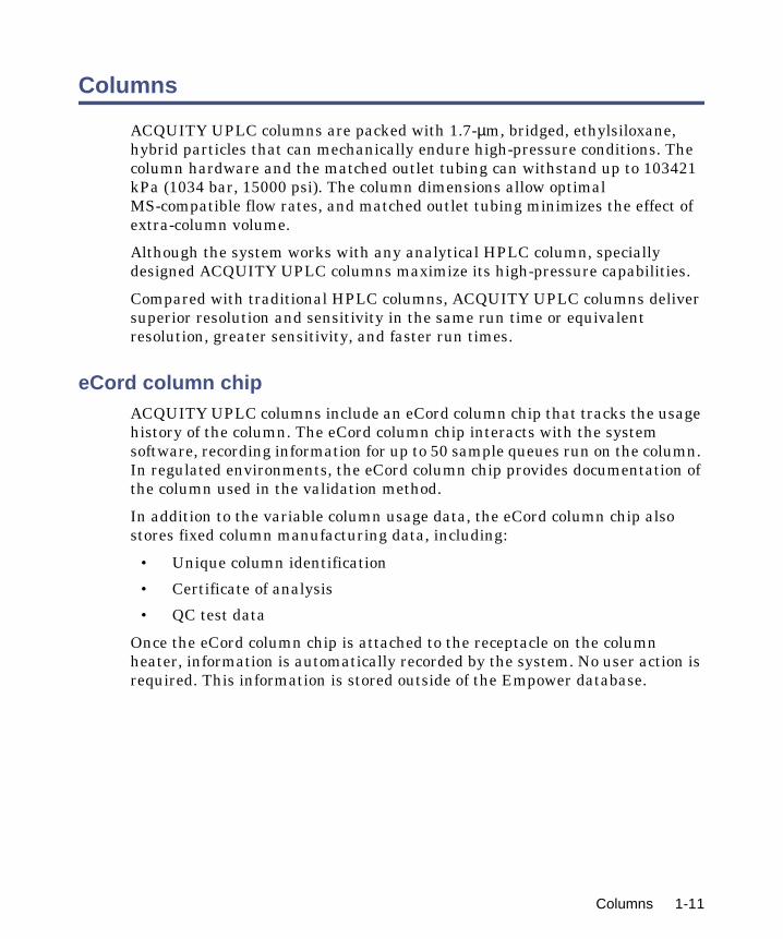
ACQUITY UPLC columns are packed with 1.7-µm, bridged, ethylsiloxane, hybrid particles that can mechanically endure high-pressure conditions. The column hardware and the matched outlet tubing can withstand up to 103421 kPa (1034 bar, 15000 psi). The column dimensions allow optimal MS-compatible flow rates, and matched outlet tubing minimizes the effect of extra-column volume.
Although the system works with any analytical HPLC column, specially designed ACQUITY UPLC columns maximize its high-pressure capabilities.
Compared with traditional HPLC columns, ACQUITY UPLC columns deliver superior resolution and sensitivity in the same run time or equivalent resolution, greater sensitivity, and faster run times.
eCord column chipACQUITY UPLC columns include an eCord column chip that tracks the usage history of the column. The eCord column chip interacts with the system software, recording information for up to 50 sample queues run on the column. In regulated environments, the eCord column chip provides documentation of the column used in the validation method.
In addition to the variable column usage data, the eCord column chip also stores fixed column manufacturing data, including:
• Unique column identification
• Certificate of analysis
• QC test data
Once the eCord column chip is attached to the receptacle on the column heater, information is automatically recorded by the system. No user action is required. This information is stored outside of the Empower database.
Columns 1-11
FlexCart
The optional FlexCart provides the ACQUITY UPLC system a mobile platform. It can hold the system instruments as well as the PC and monitor and provides electrical outlets for system instruments and integrated waste management. Used with a mass spectrometer, the cart’s adjustable height lets you position the column outlet close to the inlet probe, minimizing system dead volume.
For more information
See also:
• ACQUITY UPLC System Operator’s Guide (part number 71500082502)
• ACQUITY UPLC System Bookshelf (part number 71500082521)
• ACQUITY UPLC Photodiode Array Detector Getting Started Guide (part number 71500108703)
• ACQUITY UPLC Evaporative Light Scattering Detector Getting Started Guide (part number 71500109303)
• ACQUITY UPLC Console online Help
• ACQUITY UPLC System release notes
• Controlling Contamination in LC/MS Systems (part number 715001307) on the ACQUITY UPLC System Bookshelf CD
1-12 System Overview
2 Preparing System Hardware
Contents:
Topic Page
Powering-on the system 2-2
Monitoring startup tests 2-2
Monitoring system instrument LEDs 2-3
Preparing the binary solvent manager 2-5
Preparing the sample manager 2-14
Preparing the sample organizer 2-29
Preparing the detector 2-35
Conditioning the column 2-38
Shutting down the system 2-39
2-1
Powering-on the system
Powering-on the system entails starting each system instrument individually, as well as the ACQUITY UPLC system workstation and the Empower or MassLynx operating software.
1. Press the power switch on the top, left-hand side of each instrument’s door. Each system instrument beeps three times and runs a series of startup tests.
The power and status LEDs change as follows:
• Each system instrument’s power LED shows steady green. The binary solvent manager’s flow LED, the sample manager’s run LED, and the detector’s lamp LED all show red for a few seconds.
• During initialization, each system instrument’s power LED shows steady green. The binary solvent manager’s flow LED, the sample manager’s run LED, and the detector’s lamp LED show flashing green. Full initialization of the system usually requires about seven minutes.
• After the instruments are successfully powered-on, each one’s power LED shows steady green. The binary solvent manager’s flow LED and the sample manager’s run LED are unlit. The detector’s lamp LED shows steady green, indicating that the lamp is ignited.
2. Power-on the ACQUITY UPLC system workstation.
3. Start the Empower or MassLynx operating software. You can monitor the ACQUITY UPLC Console for messages and LED indications.
Monitoring startup tests
These startup tests run when you power-on the ACQUITY UPLC system workstation:
• CPU board
• Memory (RAM and ROM)
• External communication system (Ethernet)
• Clock
If the startup tests indicate a malfunction, see Chapter 7 in the Waters ACQUITY UPLC System Operator’s Guide.
2-2 Preparing System Hardware
Monitoring system instrument LEDs
Light emitting diodes on each system instrument indicate the instrument’s state of functioning. The LEDs are specific to their instruments, so the significance of their various colors and modes can differ from one instrument to another.
Power LEDThe power LED, on the left-hand side of an instrument’s front panel, indicates the power-on or power-off status of the instrument. This LED is green when power is on and unlit when power is off.
Tip: To provide adequate ventilation, the sample manager and sample organizer fans are always running, even with the power off. These fans switch off only when the power cable is removed from the back of the instrument.
Status LEDs
Flow LED (solvent manager)
The flow LED, to the right of the power LED on the solvent manager’s front panel, indicates the flow status. A steady green flow LED indicates that there is a flow through the solvent manager.
Run LED (sample manager and sample organizer)
The run LED, to the right of the power LED on the sample manager’s and sample organizer’s front panel, indicates the run status. A steady green run LED indicates that injections are being run.
Monitoring system instrument LEDs 2-3

Lamp LED (detector)
The lamp LED, to the right of they power LED on the detector’s front panel, indicates the lamp status. A stead green lamp LED indicates that the lamp is on.
Status LED indications
LED mode and color Description
Unlit Solvent Manager, Sample Manager, and Sample Organizer - Indicates the instrument is currently idle.
Detector - Indicates the detector lamp is extinguished.
Steady green Solvent Manager - Indicates the binary solvent manager is flowing.
Sample Manager - Indicates the sample manager is operating normally, attempting to complete any outstanding samples or diagnostic requests. When sample and diagnostic requests are finished, the LED reverts to the unlit mode.
Detector - Indicates the detector lamp is ignited.
Sample Organizer- Indicates the sample orga-nizer is operating normally, attempting to complete any outstanding samples or diagnostic requests. When sample and diagnostic requests are finished, the LED reverts to the unlit mode.
Flashing green Sample Manager - Indicates the system is waiting for at least one instrument to become operable. Detector lamp warm-up and column temperature equilibration times typically cause such a delay.
Detector - Indicates the detector is initializing or calibrating.
Flashing red Indicates an error has stopped the instrument. Information regarding the error that caused the failure can be found in the ACQUITY UPLC Console.
2-4 Preparing System Hardware

Preparing the binary solvent manager
For optimal performance of the ACQUITY UPLC™ system, you must prepare the solvent manager for operation.
To prepare the solvent manager for operation, you must perform a seal wash prime and then prime the solvent manager.
Requirement: To maintain the efficiency of the binary solvent manager, and to obtain accurate, reproducible chromatograms, use only MS-grade solvents, water, and additives. For details, see the Waters ACQUITY UPLC System Operator’s Guide.
Performing a seal wash primePrime the seal wash in the binary solvent manager to lubricate the plungers, fill the tubing paths with solvent, and flush away solvent and/or any precipitated salts that have been dragged past the plunger seals from the high-pressure side of the piston chambers.
Prime the plunger seal wash under these conditions:
• After using buffered mobile phase
• When the binary solvent manager has been inactive for a few hours or longer
Steady red Indicates an instrument failure that prevents further operation. Power-off the instrument, and then power-on. If the LED is still steady red, contact your Waters service representative.
Warning: Observe safe laboratory practices when you handle solvents. See the Material Safety Data Sheets for the solvents you use.
Caution: Chloroform and methylene chloride should not be used.
Status LED indications (Continued)
LED mode and color Description
Preparing the binary solvent manager 2-5

• When the binary solvent manager is dry
Tip: The seal wash will self-prime, but you can use a syringe to hasten the process.
Rule: To prevent contamination, do not recycle seal wash.
Recommendations:
• Seal wash should contain 10% organic solvent. This prevents microbial growth and ensures that the seal wash can solubolize the mobile phase.
• Before priming the plunger seals, ensure the volume of seal wash is adequate for priming.
See also: Controlling Contamination in LC/MS Systems (part number 715001307) on the ACQUITY UPLC System Bookshelf CD.
Required materials
• Tubing adapter (startup kit)
• 30-mL syringe (startup kit)
• Seal wash solution
Caution: To avoid damage to the solenoid valve seats and seals in the solvent path, do not use a nonvolatile buffer as the seal wash solvent.
2-6 Preparing System Hardware

To perform a seal wash prime:
1. Ensure the seal wash inlet tube is in the solvent reservoir.
2. Remove the seal wash outlet tube from the right side of the drip tray.
Binary solvent manager seal wash outlet tube
3. Push the syringe plunger fully into the syringe barrel.
4. Connect the tubing adapter to the syringe, and then connect the syringe assembly to the outlet tubing from the seal wash system.
5. In the ACQUITY UPLC Console, select Binary Solvent Manager from the system tree.
6. Click Control > Prime seal wash, and then click Yes to begin the seal wash priming process.
7. Slowly draw back on the syringe plunger to pull seal wash solvent through the system.
8. When the seal wash solution begins to flow into the syringe without major air bubbles, disconnect the tubing and reinstall it on the fitting on the drip tray.
9. Click (Stop flow) to stop the priming process.
Drip tray
Seal wash outlet tube
Preparing the binary solvent manager 2-7

Priming the binary solvent managerPriming is used to prepare a new system or binary solvent manager for use, change reservoirs or solvents, and run the system after it has been idle for more than four hours. During priming, the vent valve moves to Vent position to both ensure minimal backpressure and direct the flow to waste. The flow rate during priming is 4 mL/min for each pump being primed.
Tip: If you are priming a dry binary solvent manager, using a syringe will shorten the time required to complete priming.
Recommendation: Ensure the solvent reservoirs have enough solvent for adequate priming and the waste container has sufficient capacity for used solvent. The priming flow rate is 4 mL/min for each pump, or 8 mL/min total. For example, priming both solvents for 5 minutes requires approximately 20 mL of each solvent.
Priming a dry binary solvent manager
To prime a dry binary solvent manager:
1. Open the instrument’s front door.
2. Locate the appropriate solvent vent line.
3. In the ACQUITY UPLC Console, select Binary Solvent Manager from the system tree.
4. In the binary solvent manager information window, click Control > Prime A/B Solvents. The Prime A/B Solvents dialog box appears.
5. In the Prime A/B Solvents dialog box, select solvent A and/or B.
6. In the Time box, specify the number of minutes from 0.1 through 60.0.
Caution: To prevent salts from precipitating in the system, introduce an intermediate solvent, such as water, when changing from buffers to high-organic-content solvents. Be sure to consult the solvent miscibility tables in the Waters ACQUITY UPLC System Operator’s Guide.
Warning: To avoid spills, empty the waste container at regular intervals.
2-8 Preparing System Hardware

Default: 1.0 minute
Recommendations: Prime the binary solvent manager until a steady flow exits the vent tube (typically 7 to 10 minutes).
7. Click Start. When solvent flows out of the vent line without bubbles, the path is primed.
8. Repeat step 3 through 7 to prime the other solvents.
Requirement: There must be solvent in the A1, A2, B1, and B2 reservoirs for the degasser to function correctly.
To prime a dry binary solvent manager using a syringe:
1. Open the instrument’s front door.
2. Locate the appropriate solvent vent line.
• If you are priming solvent A, follow the stainless steel vent line that is labeled “A-VENT” from port 4 on the vent valve, and lift it out of the drip tray.
• If you are priming solvent B, follow the stainless steel vent line that is labeled “B-VENT” from port 1 on the vent valve, and lift it out of the drip tray.
Binary solvent manager vent lines
3. Push the syringe plunger fully into the syringe barrel.
4. Connect the tubing adapter to the syringe.
Drip tray
Vent valve
Solvent vent lines
Preparing the binary solvent manager 2-9

5. Connect the syringe assembly to the short length of PharMed tubing, and then connect the short length of PharMed tubing to the solvent vent line you located in step 2.
6. In the ACQUITY UPLC Console, select Binary Solvent Manager from the system tree.
7. In the binary solvent manager information window, click Control > Prime A/B Solvents. The Prime A/B Solvents dialog box appears.
8. In the Prime A/B Solvents dialog box, select solvent A1.
9. In the Time box, specify the number of minutes from 0.1 through 60.0.
Default: 1.0 minute
Recommendation: Prime the binary solvent manager until a steady flow exits the vent tube (typically 3 minutes).
10. Click Start.
11. Slowly draw back on the syringe plunger to pull solvent through the solvent path. When solvent flows out of the vent line without bubbles, the path is primed.
12. Remove the syringe from the vent line, and reconnect the vent line to the drip tray.
13. Repeat steps 6 through 12 for solvent A2, B1, and B2.
Requirement: The reservoirs for solvents A1, A2, B1, and B2 must not be empty. Otherwise the degasser will not function correctly.
Priming a wetted binary solvent managerTwo functions help prepare the system for operation. The length of time the system has been idle determines which is the better.
• Refresh system (Sys Prep)
• Start up
Refreshing the system
Use the Refresh (Sys Prep) function after the system has been idle a short period of time (a few hours to overnight) and when you plan to use the same solvents that you used previously.
2-10 Preparing System Hardware

You can invoke the Sys Prep function from the control panel or by adding it as a line in a sample set.
Recommendations:
• Prime the binary solvent manager for 1 minute if the system has been idle for 4 or more hours and you will use the solvents that are already in the system.
• Prime the binary solvent manager for 4 minutes if you will use new solvents that are of the same composition of what is already in the system.
To refresh the system:
1. In the ACQUITY UPLC Console, click Control > Refresh system (Sys Prep). The Refresh System (Sys Prep) dialog box appears.
2. Review the settings and select a different option if needed. The system primes your current solvent selections (A1 or A2, B1 or B2).
• Solvent line A only (default)
• Solvent line B only
• Both A and B
3. Click OK.
Result: The system primes the selected solvents, primes the sample manager with one weak wash prime (wash and sample syringes), and ignites the lamp in the detector.
Starting up the system
Use the Start up function to prime the binary solvent manager after changing the mobile phase, after changing the sample needle and/or sample loop, or after the system has been idle a long period of time (overnight or over a weekend). Before you begin this procedure, ensure that the system is correctly configured for use.
Recommendation: Prime the binary solvent manager for 5 minutes if you are changing to solvents whose compositions differ from the compositions of solvents already in the system.
Preparing the binary solvent manager 2-11
To start up the system:
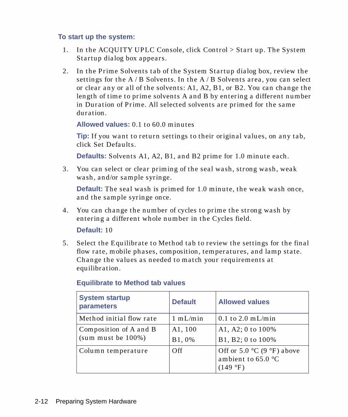
1. In the ACQUITY UPLC Console, click Control > Start up. The System Startup dialog box appears.
2. In the Prime Solvents tab of the System Startup dialog box, review the settings for the A / B Solvents. In the A / B Solvents area, you can select or clear any or all of the solvents: A1, A2, B1, or B2. You can change the length of time to prime solvents A and B by entering a different number in Duration of Prime. All selected solvents are primed for the same duration.
Allowed values: 0.1 to 60.0 minutes
Tip: If you want to return settings to their original values, on any tab, click Set Defaults.
Defaults: Solvents A1, A2, B1, and B2 prime for 1.0 minute each.
3. You can select or clear priming of the seal wash, strong wash, weak wash, and/or sample syringe.
Default: The seal wash is primed for 1.0 minute, the weak wash once, and the sample syringe once.
4. You can change the number of cycles to prime the strong wash by entering a different whole number in the Cycles field.
Default: 10
5. Select the Equilibrate to Method tab to review the settings for the final flow rate, mobile phases, composition, temperatures, and lamp state. Change the values as needed to match your requirements at equilibration.
Equilibrate to Method tab values
System startup parameters Default Allowed values
Method initial flow rate 1 mL/min 0.1 to 2.0 mL/min
Composition of A and B (sum must be 100%)
A1, 100B1, 0%
A1, A2; 0 to 100%B1, B2; 0 to 100%
Column temperature Off Off or 5.0 °C (9 °F) above ambient to 65.0 °C (149 °F)
2-12 Preparing System Hardware

6. If you changed the sample needle, click the Optional: Characterize Volume tab, and then select “Characterize seal” and “Characterize needle and loop volumes.”
7. If you changed the sample loop, in the Optional: Characterize Volume tab, select Characterize needle and loop volumes.
8. If either the needle or loop is a different size, in the Configuration area, click Change. In the Volume Configuration dialog box, select the new size of loop and/or needle, and then click OK.
9. Click Start.
Result: The lamp in the optical detector ignites, the ACQUITY UPLC system sets the column sample temperatures, and all priming starts. After priming finishes, the sample manager characterizes the needle seal if that function is selected and then logs the results of the characterizations into the database. Finally, the system establishes the method flow rate, solvent selections, and composition. The default settings for the method initial flow are 100% Solvent A1 at 1.000 mL/min and 0% B1, the column and sample temperatures are Off, and the detector lamp is ignited.
Sample temperature Off Off, or 4.0 to 40.0 °C (39.2 to 104 °F) in 25 °C (77 °F) ambient conditions
Lamp On On or off
Equilibrate to Method tab values (Continued)
System startup parameters Default Allowed values
Preparing the binary solvent manager 2-13
Preparing the sample manager
Prepare the sample manager for operation after you prepare the binary solvent manager. Preparing the sample manager involves these steps:
• Priming
• Characterizing the seal
• Characterizing the needle and sample loop volumes
• Loading sample plates
Selecting weak wash and strong wash solventsFor best performance, follow these guidelines when selecting wash solvents. Otherwise, performance may be reduced, specifically Area/Height RSD and Linearity. The guidelines do not prohibit all other solvent combinations, however. Other combinations can be run with lower performance expectations or by manipulating default injection parameters.
Use a weak wash solvent based on the sample and mobile phase chemistries of your application, making sure all solutions/buffers are miscible and soluble.
Recommendation: For buffered aqueous, reversed-phase chromatographic conditions and MS applications, use a weak wash solvent of 100% water or 0 to 25% methanol or acetonitrile and a strong wash solvent of 50 to 100% methanol or acetonitrile. High sample concentrations may require other weak wash solvents. If your separation permits, Waters recommends adding a small amount of an organic solvent (~10%) to prevent microbial growth.
Warning: To avoid solvent spills and to maintain proper leak drainage, always close the sample manager fluidics tray before operating the system.
Caution: To avoid damage to the solenoid valve seats and seals in the solvent path, do not use a nonvolatile buffer as the weak wash or strong wash solvent.
2-14 Preparing System Hardware

Tip: For best performance, the weak wash solvent should be similar or identical to your isocratic or initial gradient solvent conditions, excluding buffers. Do not use salt buffers in wash solvents.
Wash solvent effects
Property Effect
Organic species As a general principle, strong and weak solvents should include the same organic species. Note that this may not always be practicable. You may, however, use a 100% organic strong wash solvent.
Solvent composition The weak wash solvent should reflect as closely as possible the same composition as the initial gradient mobile phase.
pH Adjust the pH of strong and weak solvents for best peak shape and carryover performance.
Concentration of strong solvent
Strong solvent should be no stronger than the concentration needed to reduce carryover to an acceptable level.
Solubility of analyte and sample
The analyte and sample must be soluble in both the weak and strong wash solvents.
Caution: Proteins (in plasma, for example) do not dissolve in solvents whose organic component is greater than 40%.
Sample diluent The weak wash solvent can contact the sample, so match these as closely as possible. To offset adverse effects on peak shape caused by the matrix’s composition, adjust the weak wash composition when using the instrument in partial loop mode.
Wash volume ratio (weak to strong)
Within a method, this should be about 3:1, weak wash to strong–sufficient to ensure the weak wash flushes the strong from the needle and sample loop before sampling.
Cycle times Higher viscosity wash solvents lengthen wash cycles.
Preparing the sample manager 2-15

Priming the sample managerThe priming process fills the sample needle with solvent, flushes new solvent through the injector lines, and/or purges air from the lines. You prime the sample needle and/or sample syringe to accomplish these tasks:
• Preparing a new sample manager for operation
• Preparing a sample manager for operation after has been idle for an extended period
• Changing the solvent in the syringes
• Removing bubbles from the lines
Guidelines: Ensure that the priming solvent is correctly composed and that it is high in quality and miscible with any other solvents used in your system. Use filters in all solvent reservoirs, and ensure the volumes of solvents are sufficient for priming.
Requirement: The sample manager must be primed before you attempt to characterize the seal.
2-16 Preparing System Hardware
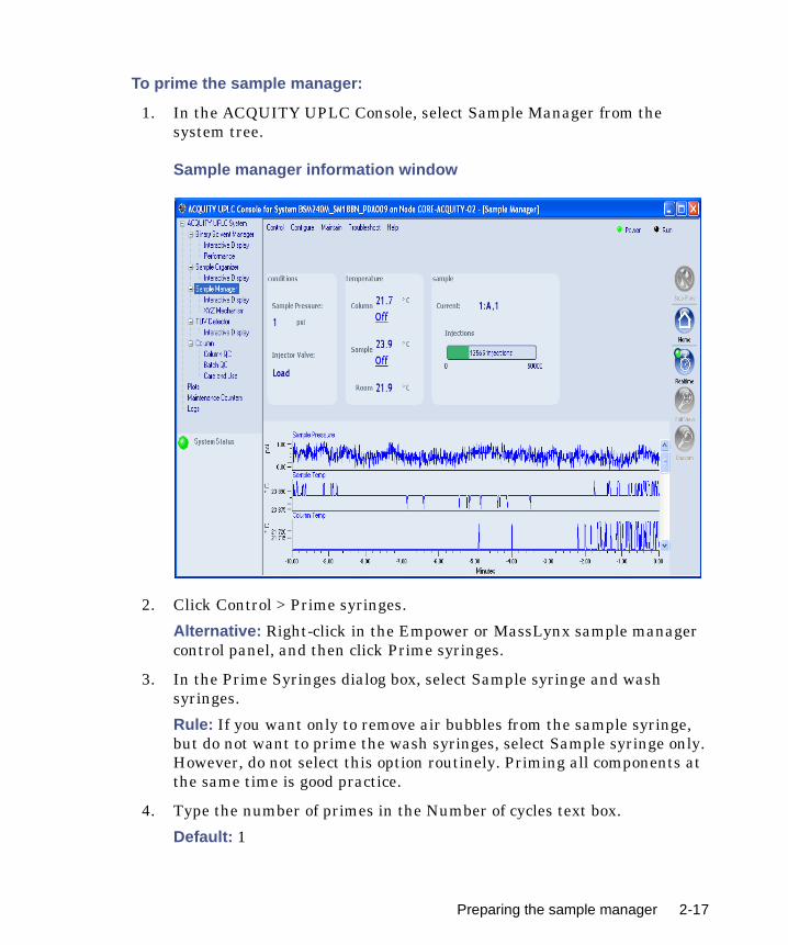
To prime the sample manager:
1. In the ACQUITY UPLC Console, select Sample Manager from the system tree.
Sample manager information window
2. Click Control > Prime syringes.
Alternative: Right-click in the Empower or MassLynx sample manager control panel, and then click Prime syringes.
3. In the Prime Syringes dialog box, select Sample syringe and wash syringes.
Rule: If you want only to remove air bubbles from the sample syringe, but do not want to prime the wash syringes, select Sample syringe only. However, do not select this option routinely. Priming all components at the same time is good practice.
4. Type the number of primes in the Number of cycles text box.
Default: 1
Preparing the sample manager 2-17

Recommendation: Waters recommends 5 to 7 primes when you are changing solvents.
5. Click OK to start priming. When the system status is “Idle,” priming is finished.
Tip: Each prime takes approximately 2 to 4 minutes.
Washing the sample manager needleWashing the needle is an optional procedure that flushes strong and/or weak wash solvent through the needle and injection port. Washing the needle removes contaminants from the inside and outside of the needle, the external piercing needle, and the injection port. You can also perform a needle wash to ascertain proper flow through the waste tubing and to confirm that the needle wash system is primed and properly operating.
Rule: Do not use buffered solvents as wash solvents.
Tip: Priming the system washes the sample needle, so whenever you prime the system, you can omit this procedure.
Observing wash solvent recommendations
Waters recommends that you observe these guidelines for washing the needle:
• To ensure that the strong wash solvent is completely removed, the system washes the needle with 500 µL of weak wash solvent after you use strong wash solvent. You can increase, but not decrease, the default value of 500 µL.
• The analytes and sample matrix must be soluble in both weak and strong solvents. Proteins do not dissolve in solvents whose organic component is greater than 40%. Buffers should not be used in any wash solvent.
Example: If the weak wash solvent is 30% acetonitrile and 70% water, the strong wash solvent should contain a greater concentration of acetonitrile in water.
Caution: Do not abort the sample manager priming sequence. Doing so may leave strong solvent in the sample needle which can adversely affect chromatography.
2-18 Preparing System Hardware

• The weak wash solvent should be the same as the initial eluting solvent, and the strong wash solvent should at least equal the composition of the final eluting solvent.
• Use a weak wash solvent based on the sample and mobile phase chemistries of your application. Make sure all solutions are miscible and soluble. For best results, weak wash solvent should match the initial gradient conditions and mobile phase composition (isocratic). High sample concentrations can require additional weak wash solvents.
• For buffered aqueous, reversed-phase chromatography, use weak wash solvent consisting of 100% water or up to 25% methanol or acetonitrile. For strong wash solvent, use 50 to 100% methanol or acetonitrile.
Before you begin, ensure that the solvents are compatible with your application, that their volumes are sufficient, and that the waste reservoir is large enough to contain the waste solvent.
To wash the sample manager needle:
1. In the ACQUITY UPLC Console, select Sample Manager from the system tree. The sample manager information window appears.
2. Click Control > Wash Needle.
Alternative: Right-click in the Empower or MassLynx sample manager control panel, and then click Wash Needle. The Wash Needle dialog box appears.
3. In the Strong Wash box, specify the volume for the strong wash solvent.
Range: 0.0 through 99999 µL
Exception: To omit strong wash solvent, enter 0 in the Strong Wash box, or leave it blank.
Default: 0.0 µL
Recommendation: 100 through 500 µL
Tip: Using both a weak and strong wash solvent increases the wash time and solvent consumption because the system must be fully cleansed of the strong solvent before starting the next injection.
4. In the Weak Wash box, specify the volume for the weak wash solvent.
Range: 1.0 through 99999 µL
Default: 200.0 µL without strong wash or 500 µL with strong wash
Preparing the sample manager 2-19

,
Recommendation: 200 through 500 µL or three times the strong wash volume
5. Click OK. The needle wash begins.
6. When needle washing is complete, the status returns to Idle.
To stop a needle wash routine before it finishes:
From the sample manager information window, click Control > Reset SM.
Alternative: Right-click in the Empower or MassLynx sample manager control panel, and then click Reset SM.
Characterizing the needle sealThe needle seal characterization procedure finds the position at which the needle obtains a seal within the wash station block. The sample manager must be primed before starting this procedure.
Requirements:
• Perform this procedure before calibrating the needle and sample loop volumes.
• Perform this procedure after priming the sample manager or after you replace and/or adjust these items:
• The needle
• Any part of the needle assembly
• The needle (Z) or piercing needle (Zp) flags (home and top-of-plate)
• A home or top-of-plate sensor
• The inject port seal
• The wash station
• The NVRam battery on the CPU2000
Caution: If you do not use a sufficient quantity of weak wash solventthe strong wash solvent may contact the sample, corrupting it.
Caution: Do not abort the sample needle wash sequence. Doing so may leave strong solvent in the sample needle which can adversely affect chromatography.
2-20 Preparing System Hardware

To characterize the needle seal:
1. In the ACQUITY UPLC Console, select Sample Manager from the system tree. The sample manager information window appears.
2. Click Maintain > Characterize > Needle seal. The Characterize Needle Seal dialog box appears.
3. Click Start. The calibrate seal operation begins, and the sample manager status displays “Calibrating seal.”
4. When calibration ends, the sample manager status displays “Idle.”
5. Click Results to view the results of the needle seal characterization operation.
Characterizing the needle and sample loop volumesWhenever you replace the sample loop and/or the sample needle, you must set the system to characterize the volume of the replacement parts. Do this regardless of whether the sizes of the replacement parts are nominally the same as those of the original parts or differ from them. Also perform this procedure when the composition of the weak wash solvent changes, because solvent characteristics such as viscosity, surface tension, and polarity can change. During sample injection, the weak wash solvent precedes and follows the sample in the fluid-carrying lines, so the sample is directly affected by the weak wash solvent.
Characterizing the loop volume compares the loop’s nominal volume (in µL) to its measured volume.
Characterizing the needle volume compares the needle’s nominal volume (in µL) to its measured volume.
Tip: Characterizing the system volume is critical to acceptable sample manager performance.
Requirements:
• Specify the sizes of the sample needle, loop, and syringe in the Volumes dialog box before characterizing the volumes.
• Prime the sample manager, and characterize the seal before characterizing the volumes.
• Create a method (using Empower or MassLynx software) that has the same air gap and sample draw rate that you will be using.
Preparing the sample manager 2-21

To characterize the needle and sample loop volumes:
1. In the ACQUITY UPLC Console, select Sample Manager from the system tree.
2. Click Maintain > Characterize> Needle and loop volumes. The Characterize Needle and Loop Volumes dialog box appears.
3. Click Start. The needle and loop volumes characterization operation begins.
Tip: This procedure takes at least 5 minutes.
4. Click Results to view the results of the needle and loop volumes characterization operation.
Result: If the needle fails the test, suspect it is bent, broken, or blocked. If the sample loop fails the test, suspect that it is blocked or leaking, that it has a loose fitting, or that the draw rate is too high.
Loading sample plates in the sample managerThe ACQUITY UPLC sample manager holds up to two ANSI plates that you load through the front door. The left plate is referred to as position 1, the right plate as position 2.
Exception: If the optional sample organizer is installed, you can load only one plate through the sample manager front door. You must load the plate on the right-hand tray. In this case, the right-hand tray becomes the number one position.
To load a sample plate:
1. Open the ACQUITY UPLC sample manager door.
2. Squeeze the tray button while you pull the tray toward you.
3. Load the plate onto the tray so that well position A,1 is at the right-rear corner and the forward edge of the plate is behind the spring inside the front of the carrier.
2-22 Preparing System Hardware

4. Slide the tray into the sample manager until it clicks into place.
Sliding tray into sample manager
5. Close the sample compartment door. A mechanism on the door ensures the plates are positioned correctly when the door closes.
Selecting the optimum sample injection modeThe sample manager supports three injection modes – Partial Loop Needle Overfill, Partial Loop, and Full Loop.
• Partial Loop Needle Overfill Mode – the best general purpose mode for partial loop injection. It provides the best partial loop accuracy, precision and linearity for a wide range of samples, including strong and weak acids and bases, hydrophilic, and hydrophobic compounds. It is recommended as the first choice mode, except where there are clear indications for the others.
• Partial Loop Mode – should be reserved for those situations where analysis time takes precedence over any other concern, where the sample volume is very limited, or where the injection volume is very large.
Caution: The plates must be positioned correctly to avoid damaging the sample needle.
TP02389
Sample plate
Button
Plate tray
A-1 well position
Preparing the sample manager 2-23

• Full Loop Mode – should be chosen whenever accuracy and precision are the primary concerns. It is the recommended mode when using 1.0 mm I.D. columns.
Partial Loop Needle Overfill mode guidelines
• Provides optimum performance when injection volumes are maintained within a range of 10 to 75% nominal loop volume.
• The generally accepted practice for partial loop injection linearity restricts the injection volume selected to ≤ 50% nominal loop volume. However, you can increase the usable loop volume to ≤ 75% nominal loop volume by selecting the Needle Overfill technique.
• These recommendations are based on achieving an injection-to-injection variability of ≤ 1% across the specified volume range. In addition, the correlation between specified injection volume and peak area must be R2>0.999 and the Area % RSD is < ±1.0.
Load Ahead mode guidelines
• The first injection of a sample set will not utilize Load Ahead mode.
• Injections sets with different methods will not utilize Load Ahead mode.
• The minimum cycle time is the lesser of either the two run times or sample preparation and wash.
2-24 Preparing System Hardware
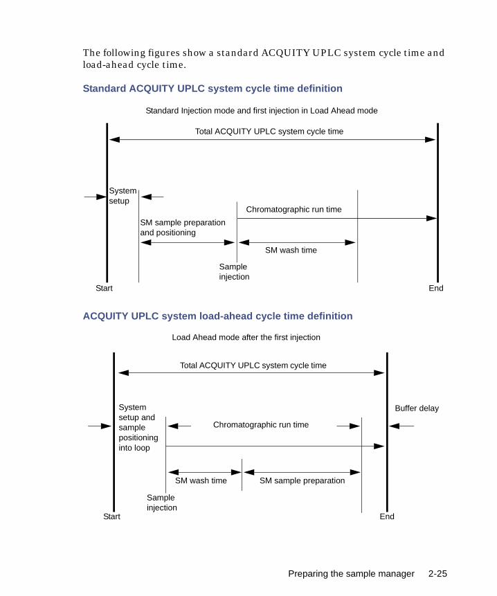
The following figures show a standard ACQUITY UPLC system cycle time and load-ahead cycle time.
Standard ACQUITY UPLC system cycle time definition
ACQUITY UPLC system load-ahead cycle time definition
SM wash time
Start End
Chromatographic run time
SM sample preparationand positioning
Sample injection
Systemsetup
Standard Injection mode and first injection in Load Ahead mode
Total ACQUITY UPLC system cycle time
EndStart
Sample injection
Total ACQUITY UPLC system cycle time
Load Ahead mode after the first injection
Chromatographic run time
SM sample preparationSM wash time
Buffer delaySystem setup and sample positioning into loop
Preparing the sample manager 2-25
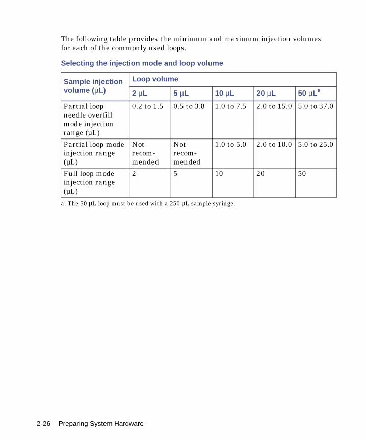
The following table provides the minimum and maximum injection volumes for each of the commonly used loops.
Selecting the injection mode and loop volume
Sample injection volume (µL)
Loop volume
2 µL 5 µL 10 µL 20 µL 50 µLa
a. The 50 µL loop must be used with a 250 µL sample syringe.
Partial loop needle overfill mode injection range (µL)
0.2 to 1.5 0.5 to 3.8 1.0 to 7.5 2.0 to 15.0 5.0 to 37.0
Partial loop mode injection range (µL)
Not recom-mended
Not recom-mended
1.0 to 5.0 2.0 to 10.0 5.0 to 25.0
Full loop mode injection range (µL)
2 5 10 20 50
2-26 Preparing System Hardware

Installing the sample manager shadeIf your samples are light-sensitive, you should install the sample manager foam shade over the sample compartment window.
Required material
• Sample manager foam shade
To install the sample manager foam shade:
1. Insert the foam shade over the outside of the sample compartment window.
Inserting the foam shade
Foam shade
Sample compartment window
Preparing the sample manager 2-27

2. Press the foam shade into place over the window.
Foam shade pressed into place
Foam shade
2-28 Preparing System Hardware

Preparing the sample organizer
If your system includes a sample organizer, prepare it for operation according to the procedures in this section.
Initiating communications
To initiate communications between the sample manager and sample organizer:
1. Open the sample manager door, load a plate onto the right-hand tray, and then close the sample manager door.
Tip: When the system has both a sample manager and a sample organizer, the right-hand tray of the sample manager becomes position number one, and the left-hand tray is not available. The bottom shelf in the sample organizer becomes position number two.
Exception: If the system does not include a sample organizer, the left-hand tray in the sample manager is designated position number one, the right-hand tray, position number two.
2. In the ACQUITY UPLC Console, select Sample Manager from the system tree.
3. In the sample manager information window, click Configure > Sample Organizer. The Sample Organizer Configuration dialog box appears.
4. Select the sample organizer from the list of serial numbers in the drop-down list, and then click OK.
5. The sample organizer automatically detects which shelves contain plates and illuminates their corresponding LEDs.
Preparing the sample organizer 2-29

Loading sample platesThe sample organizer holds up to 21 ANSI plates that you load through the front door. However, the actual number of plates you can load depends on their height. When the system has both a sample manager and sample organizer, the right-hand shelf in the sample manager is referred to as position 1 and the bottom shelf in the sample organizer as position 2.
To load sample plates:
1. Open the sample organizer door.
2. Pull the shelf toward you.
3. Load the plate onto the shelf so that position A,1 is at the right-rear corner and the forward edge of the plate is behind the stop at the left front corner.
Loading the sample plate
4. Ensure that the plate does not extend beyond the plate stop at the back of the shelf.
Caution: To prevent spillage, use Waters-approved cap mats, sealing caps, or heat seal film on the samples. Consult the current ACQUITY UPLC system release notes for a list of approved sample covers.
TP02504
Shelf label
2-30 Preparing System Hardware

5. Slide the shelf into the sample organizer until it stops.
Shelf/plate combination and restrictors
6. Repeat steps 2 through 5 for the remaining plates.
7. Close the sample organizer door. A mechanism on the door ensures the shelves are positioned correctly when the door closes.
8. Click Configure > Scan and store shelf layout to update and save the new shelf configuration.
To remove and replace the same plate on the same shelf:
1. Open the sample organizer door, and then remove plates that have finished processing.
2. Pull a shelf toward you, and then insert a plate of the same type and size on the shelf.
3. Load a plate onto a shelf so that position A,1 is at the right-rear corner and the forward edge of the plate is behind the stop at the left-front
Caution: To ensure the transfer shuttle moves freely and without damaging the sample organizer, you must be able to slide a shelf/plate/vial combination in or out without interfering with the restrictors directly above and below it.
Caution: To avoid jarring the plates from their shelves, do not slam the sample organizer door closed.
Shelf
Sample plate
Restrictors
Preparing the sample organizer 2-31
corner. Ensure that the plate does not extend beyond the plate stop at the back of the shelf.
4. Slide the shelf into the sample organizer until it stops.
5. Repeat steps 3 and 4 until all plates and holders are placed correctly on the shelves.
6. Close the sample organizer door. A mechanism on the door ensures the shelves are positioned correctly when the door closes.
7. Click Verify. The sample organizer automatically scans the plates and shelves, senses which shelves contain plates, compares them to the saved layout, verifies that they match, and illuminates the corresponding LEDs inside the sample organizer door.
8. Configure the plates and shelves in the Empower or MassLynx data application.
Tip: You can load plates and shelves either before or after configuring them in the data application, but you must configure them before running samples.
To rearrange the shelves for a different plate configuration:
1. Open the sample organizer door, and then remove plates that have finished processing.
2. Add, move, or remove shelves from the sample organizer so that the shelf configuration suits the plates you intend to run. Standard microtiter plates need one slot. Intermediate plates need two slots, so allow empty slots above the plate or holder. Deep-well plates and all vial
Caution: To prevent spillage, use Waters-approved cap mats, sealingcaps, or heat seal film on the samples. Consult the current ACQUITYUPLC system release notes for a list of approved sample covers.
Caution: To ensure the transfer shuttle moves freely and without damaging the sample organizer, you must be able to slide a shelf/plate/vial combination in or out without interfering with the restrictors directly above and below it.
Caution: To avoid jarring the plates from their shelves, do not slam the sample organizer door closed.
2-32 Preparing System Hardware

holders need three slots, so allow two empty slots above the plate or holder.
3. Load a plate onto a shelf so that position A,1 is at the right-rear corner and the forward edge of the plate is behind the stop, at the left-front corner. Ensure that the plate does not extend beyond the plate stop at the back of the shelf.
4. Slide the shelf into the sample organizer until it stops.
5. Repeat steps 3 and 4 until all plates and holders are placed correctly on shelves.
6. Close the sample organizer door. A mechanism on the door ensures the shelves are positioned correctly when the door closes.
7. Click Configure > “Scan and store shelf layout”.
The sample organizer initializes and scans the shelves. When it detects a new shelf, it illuminates the LED to the left of the shelf, inside the sample organizer door.
Tip: In the ACQUITY UPLC Console, a thin, grey bar appears for each empty shelf. After the plate or shelf is configured using Empower or MassLynx software, plate identification appears in a thicker bar.
8. Configure the plates and shelves in the Empower or MassLynx data application.
Tip: You can load plates and shelves either before or after configuring them in the data application, but you must configure them before running samples.
Caution: To prevent spillage, use Waters-approved cap mats, sealingcaps, or heat seal film on the samples. Consult the current ACQUITYUPLC system release notes for a list of approved sample covers.
Caution: To ensure the transfer shuttle moves freely and without damaging the sample organizer, you must be able to slide a shelf/plate/vial combination in or out without interfering with the restrictors directly above and below it.
Caution: To avoid jarring the plates from their shelves, do not slam the sample organizer door closed.
Preparing the sample organizer 2-33
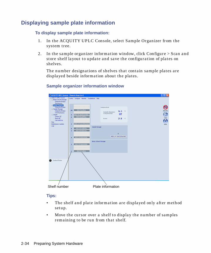
Displaying sample plate information
To display sample plate information:
1. In the ACQUITY UPLC Console, select Sample Organizer from the system tree.
2. In the sample organizer information window, click Configure > Scan and store shelf layout to update and save the configuration of plates on shelves.
The number designations of shelves that contain sample plates are displayed beside information about the plates.
Sample organizer information window
Tips:
• The shelf and plate information are displayed only after method setup.
• Move the cursor over a shelf to display the number of samples remaining to be run from that shelf.
Shelf number Plate information
2-34 Preparing System Hardware

Preparing the detector
If your system includes a TUV detector, prepare it for operation by following the procedures in this section.
See also: If your system includes a PDA detector, see the ACQUITY UPLC Photodiode Array Detector Getting Started Guide for information on preparing it.
See also: If your system includes an ELS detector, see the ACQUITY UPLC Evaporative Light Scattering Detector Getting Started Guide for information on preparing it.
See also: If your system includes a mass spectrometer, see the documentation that accompanies the instrument for information on preparing it.
Preparing the TUV detector
Starting the TUV detector
Tip: To prevent errors on startup, be sure the flow cell contains degassed, transparent solvent (acetonitrile or water) and the detector door is closed firmly.
To start the TUV Detector:
1. Ensure the detector flow cell is filled with degassed, transparent solvent (acetonitrile or water) and free of air bubbles. The detector might not initialize correctly if the cell contains air.
2. Ensure the detector door is closed firmly.
3. Press the power switch on the door to power-on the detector. The detector beeps three times and runs a series of startup tests while the lamp LED blinks. The power LED shows steady green.
Initialization usually requires approximately 2 minutes, and lamp warm-up requires approximately 3 minutes.
Caution: Use only thoroughly degassed HPLC-grade solvents. Gas in the mobile phase can form bubbles in the flow cell and cause the detector to fail the startup diagnostic tests.
Preparing the detector 2-35

4. When the lamp LED shows steady green, start the Empower or MassLynx software. You can monitor the ACQUITY UPLC Console for messages and LED indications. For best results, allow at least 30 minutes to equilibrate the detector and stabilize the baseline.
Tip: The absorbance value appears in the ACQUITY UPLC Console and also in Empower’s Run Samples window or MassLynx’s Inlet Editor window. If the detector is in dual wavelength mode, two absorbance values appear.
Absorbance values have a resolution of 0.0001 AU.
When the lamp is extinguished, “Lamp Off” appears in the software instead of absorbance values.
5. Configure the detector according to the instructions in the Empower or MassLynx online Help.
See also: “Configuring Empower” on page 3-2 and “Configuring MassLynx software” on page 3-12.
TUV Detector information window
2-36 Preparing System Hardware

Recording sample and reference energies
After you install the detector or perform maintenance tasks, like changing the lamp or flow cell, complete the procedures in this section to verify that the detector optics and electronics work properly.
To record sample and reference energies:
1. Ensure that the detector is connected to the workstation.
2. Flush the system tubing with filtered, degassed HPLC-grade acetonitrile.
3. Pump mobile phase for 15 minutes or more at 0.3 mL/min.
4. Ensure the detector cell is filled with solvent and free of air bubbles.
Tip: The detector may not initialize correctly if air is present in the cell.
5. When both LEDs show steady green, initialization is complete.
6. Start the Empower or MassLynx software.
7. Launch the ACQUITY UPLC Console from the sample manager control panel.
See also: “Starting the ACQUITY UPLC Console from Empower” on page 3-11 and “Starting the ACQUITY UPLC Console from MassLynx software” on page 3-13.
8. Select the TUV detector view in the ACQUITY UPLC Console.
9. Set the wavelength to 230 nm.
10. In the Console, select TUV Detector > Interactive Display from the system tree.
11. Record the sample and reference energies at 230 nm.
Caution: The maximum allowable pressure drop across the flow cell is 6895 kPa (69 bar, 1000 psi). If the solvent is viscous (methanol-water, for example), you may need to decrease the maximum flow rate to prevent breaking the cell.
Preparing the detector 2-37

Conditioning the column
Conditioning the column involves running a solvent gradient through it without injecting samples or running the Events table. The run time for conditioning the column should equal the gradient table run time.
To condition the column:
1. Remove the column inlet line from the detector, and place the end in a small waste container.
2. If Empower software controls the system, proceed as follows:
a. In the Samples table, add a row to the method.
b. Select Equilibrate/Condition Column (Isocratic or Gradient) as the function in the new row.
c. Run the separation method. The system runs the gradient.
3. If MassLynx software controls the system, proceed as follows:
a. Open the Sample Set window, and select an inlet method that includes the chromatographic conditions you want to use.
b. In the Samples table, add an inlet prerun field.
c. In the Run Samples page, select Samples > Format > Customize.
d. In the Custom Field Display window, select Inlet prerun.
e. To save the column as part of the window, save the sample set format.
f. Select method setup in the Sample Set window as a pre-inlet method.
g. Select a method for the inlet file (these methods can be the same).
h. Run the sample set line. The system runs the condition column method and then runs the separation method.
Caution: To prevent damage to the detector flow cell, ensure that the waste solvent does not flow through the detector during this procedure. After installing a new column, flush solvent through it and out to waste before connecting the column to the detector (for example, 10 column volumes).
2-38 Preparing System Hardware
See also: For more information about column conditioning, consult the Empower online Help.
Tip: The run time for conditioning a column should equal the gradient table run time.
Shutting down the system
You might want to shut down the system
• between analyses
• overnight
• for a weekend
• for 72 hours or more
Tips:
• If you are using Empower software to control the system, set system shutdown parameters in the Instrument Method Editor. Consult the Empower online Help for more information.
• If you are using MassLynx software to control your system, set system shutdown parameters in the Shutdown Editor. Consult the MassLynx online Help for more information.
Between analyses
To shut down the system between analyses:
1. Between analyses, continue to pump the initial mobile phase mixture through the column. Doing so maintains the column equilibrium necessary for good retention time reproducibility.
2. If a few hours will pass before the next injection, slow the flow rate in the interim to a few tenths of a mL/min to conserve solvent.
Tip: Ensure that Auto-Shutdown for your shutdown method is deactivated.
Caution: Buffers left in the system can precipitate and damage instrument components.
Shutting down the system 2-39
3. Keep the detector operating and the column heater at operating temperature during this period.
Shutting down for fewer than 72 hours
To shut down the system for fewer than 72 hours:
1. Flush the column with 100% acetonitrile. Doing so keeps the column bed in an active, wetted state.
See also: Waters ACQUITY UPLC BEH Column Care and Use Instructions.
Requirement: If you are using buffers, you must first flush the column with a high-water-content mobile phase (90% water). Then stop the pump flow.
2. Extinguish the detector lamp to lengthen lamp life.
3. The column heater can operate overnight but should be shut down over a weekend.
Shutting down for more than 72 hours
To shut down the system for more than 72 hours:
1. Follow the steps for shutting down the system for fewer than 72 hours, above.
See also: Waters ACQUITY UPLC BEH Column Care and Use Instructions.
2. After flushing the column and letting it cool to ambient temperature, disconnect the inlet and outlet tubes, and join them with a union. Install end-plugs in the column inlet and outlet fittings, and then return the column carefully to its box for storage.
Warning: Risk of electric shock. The power switch on each system instrument controls the basic operational state of that instrument. Nevertheless, some instrument circuits remain live after the instrument is switched off. To completely interrupt power to a system instrument, set the power switch to Off, and then unplug the instrument’s power cord from the AC outlet.
2-40 Preparing System Hardware

3. Pump water through the system (including the binary solvent manager, sample manager, and detectors) for 10 to 20 minutes at 0.5 mL/min, followed by isopropyl alcohol for another 10 to 20 minutes. Then turn the pump off, leaving isopropyl alcohol in the fluid lines.
Caution: Before using any system instruments for another type of analysis, ensure that the mobile phase for the new analysis is miscible with methanol, water, methanol/acetonitrile, or isopropyl alcohol. Likewise, before restarting the system, ensure that any residual material not miscible with the initial methanol/water mobile phase has been flushed thoroughly from the system with an appropriate intermediate solvent.
Shutting down the system 2-41

2-42 Preparing System Hardware

3 Configuring System Software
Contents:
Topic Page
Configuring Empower 3-2
Starting the ACQUITY UPLC Console from Empower 3-11
Configuring MassLynx software 3-12
Starting the ACQUITY UPLC Console from MassLynx software 3-13
3-1

Configuring Empower
Perform these tasks to configure Empower:
• Start the software and log in
• Select system instruments
• Name the system
Starting Empower and logging in
To start Empower and log in:
1. Select Start > Programs (for Windows XP, All Programs) > Empower > Empower Login. The Empower Login dialog box appears.
Alternative: You can also start Empower through the Empower desktop shortcut.
2. Type your user name and password.
3. Click OK.
Selecting system instruments
To select system instruments:
1. In the Empower Pro window, click Configure System.
2. In the Configuration Manager window, click Acquisition Servers, right-click the node name, and then select Properties.
Tip: If you are using Empower 1154 software to control the system, the node name is referred to as the acquisition server name.
3-2 Configuring System Software

3. In the Acquisition Server dialog box, click the Instruments tab. The system instruments that are successfully communicating with your system are shown with a Yes in the “OK?” column.
Instruments tab
4. Ensure that a binary solvent manager (ACQ-BSM), sample manager (ACQ-SM), and detector (ACQ-TUV, ACQ-PDA, or ACQ-ELS) appear in the instrument list, and then click OK.
5. Right-click Systems, and then select New > Chromatographic System.
6. In the System Type area of the New Chromatographic System Wizard dialog box, select Create New System, and then click Next.
System Selection dialog box
7. In the System Selection dialog box, drag the name of the instrument, or instruments, you want to include in the new system from the Available Instruments pane to the New System Instruments pane. Click Next.
Configuring Empower 3-3

8. When the Access Control dialog box appears, click Next.
9. In the Name Selection dialog box, specify a name for your system. Enter comments, if any, and then click Finish. A confirmation dialog box appears.
10. Click Projects, right-click a project, and then select Open.
11. In the Project window, click Run Samples . The Run Samples window appears.
Alternative: You can also access the Run Samples window via Empower’s QuickStart menu.
The Run Samples window contains control panels for the binary solvent manager, sample manager, and detector.
Control panels
About the binary solvent manager control panelIf Empower software controls the system, the binary solvent manager’s control panel appears at the bottom of the Run Samples window. If MassLynx software controls the system, the binary solvent manager’s control panel appears at the bottom of the Inlet Editor window.
Binary solvent manager control panel
The binary solvent manager control panel displays flow status, system pressure, total flow rate, and solvent composition parameters. You may edit these when the system is idle by clicking on the underlined value. You cannot
Status
Flow LED
System pressure
Total flow rateStop flow
Solvent composition
3-4 Configuring System Software
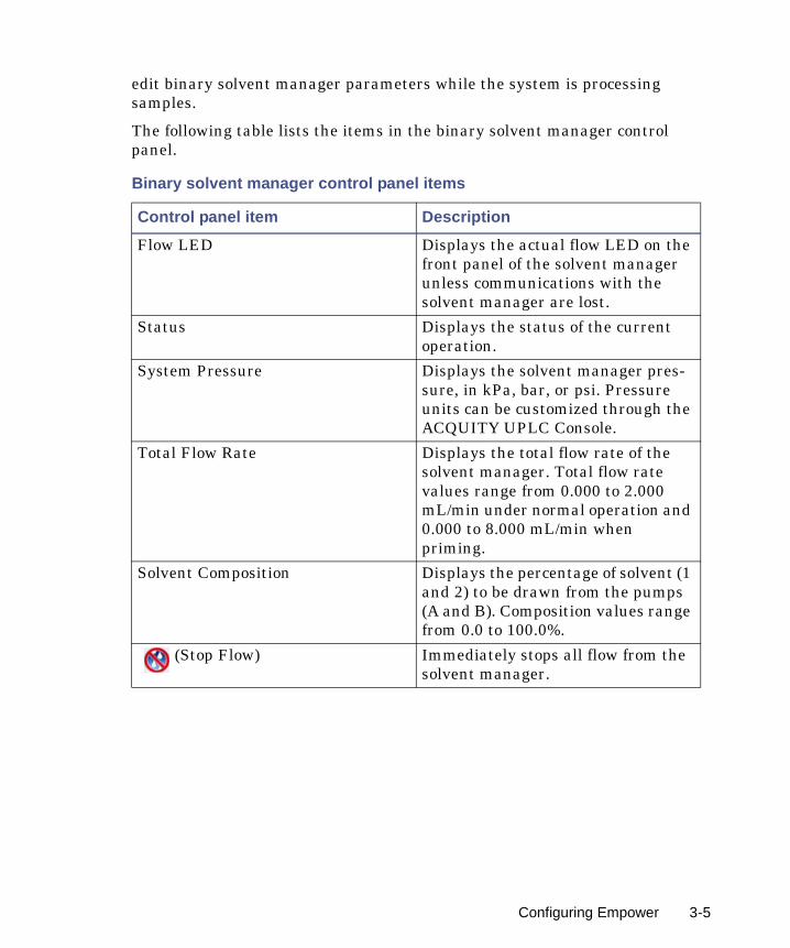
edit binary solvent manager parameters while the system is processing samples.
The following table lists the items in the binary solvent manager control panel.
Binary solvent manager control panel items
Control panel item Description
Flow LED Displays the actual flow LED on the front panel of the solvent manager unless communications with the solvent manager are lost.
Status Displays the status of the current operation.
System Pressure Displays the solvent manager pres-sure, in kPa, bar, or psi. Pressure units can be customized through the ACQUITY UPLC Console.
Total Flow Rate Displays the total flow rate of the solvent manager. Total flow rate values range from 0.000 to 2.000 mL/min under normal operation and 0.000 to 8.000 mL/min when priming.
Solvent Composition Displays the percentage of solvent (1 and 2) to be drawn from the pumps (A and B). Composition values range from 0.0 to 100.0%.
(Stop Flow) Immediately stops all flow from the solvent manager.
Configuring Empower 3-5

You can access additional functions by right-clicking anywhere in the solvent manager control panel:
Additional functions in the binary solvent manager control panel
Control panel function Description
Refresh system (Sys Prep) Refreshes the fluid-carrying lines according to the current method conditions.See also: “Refreshing the system” on page 2-10.
Startup Brings the system to operational conditions after an extended idle period or when switching to different solvents.See also: “Starting up the system” on page 2-11.
Prime A/B solvents Displays the Prime A/B Solvents dialog box.See also: “Priming the binary solvent manager” on page 2-8.
Prime seal wash Displays the Prime Seal Wash dialog box.See also: “Performing a seal wash prime” on page 2-5.
Reset BSM Resets the solvent manager after an error condition.
Help Displays the ACQUITY UPLC Console online Help.
3-6 Configuring System Software
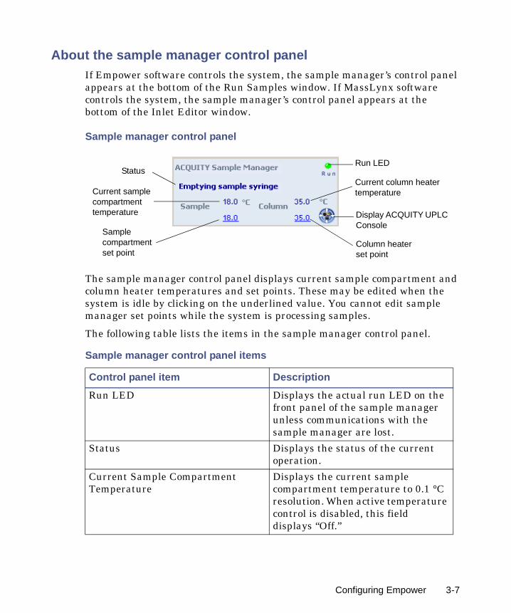
About the sample manager control panelIf Empower software controls the system, the sample manager’s control panel appears at the bottom of the Run Samples window. If MassLynx software controls the system, the sample manager’s control panel appears at the bottom of the Inlet Editor window.
Sample manager control panel
The sample manager control panel displays current sample compartment and column heater temperatures and set points. These may be edited when the system is idle by clicking on the underlined value. You cannot edit sample manager set points while the system is processing samples.
The following table lists the items in the sample manager control panel.
Sample manager control panel items
Control panel item Description
Run LED Displays the actual run LED on the front panel of the sample manager unless communications with the sample manager are lost.
Status Displays the status of the current operation.
Current Sample Compartment Temperature
Displays the current sample compartment temperature to 0.1 °C resolution. When active temperature control is disabled, this field displays “Off.”
Run LED
Current column heater temperature
Display ACQUITY UPLC Console
Column heater set point
Status
Current sample compartment temperature
Sample compartment set point
Configuring Empower 3-7

You can access additional functions by right-clicking anywhere in the sample manager control panel:
Sample Compartment Set Point Displays the current sample compartment set point to 0.1 °C resolution. When active temperature control is disabled, this field displays “Off.”
Current Column Heater Temperature
Displays the current column heater temperature to 0.1 °C resolution, even when active temperature control is disabled.
Column Heater Set Point Displays the current column heater set point to 0.1 °C resolution. When active temperature control is disabled, this field displays “Off.”
(Display Console) Displays the ACQUITY UPLC Console.
Additional functions in the sample manager control panel
Control panel function Description
Run Sys Prep Primes the sample manager with one weak wash prime (wash and sample syringes).See also: “Refreshing the system” on page 2-10.
Prime syringes Displays the Prime Syringes dialog box.See also: “Priming the sample manager” on page 2-16.
Wash needle Displays the Wash Needle dialog box.See also: “Washing the sample manager needle” on page 2-18.
Sample manager control panel items (Continued)
Control panel item Description
3-8 Configuring System Software
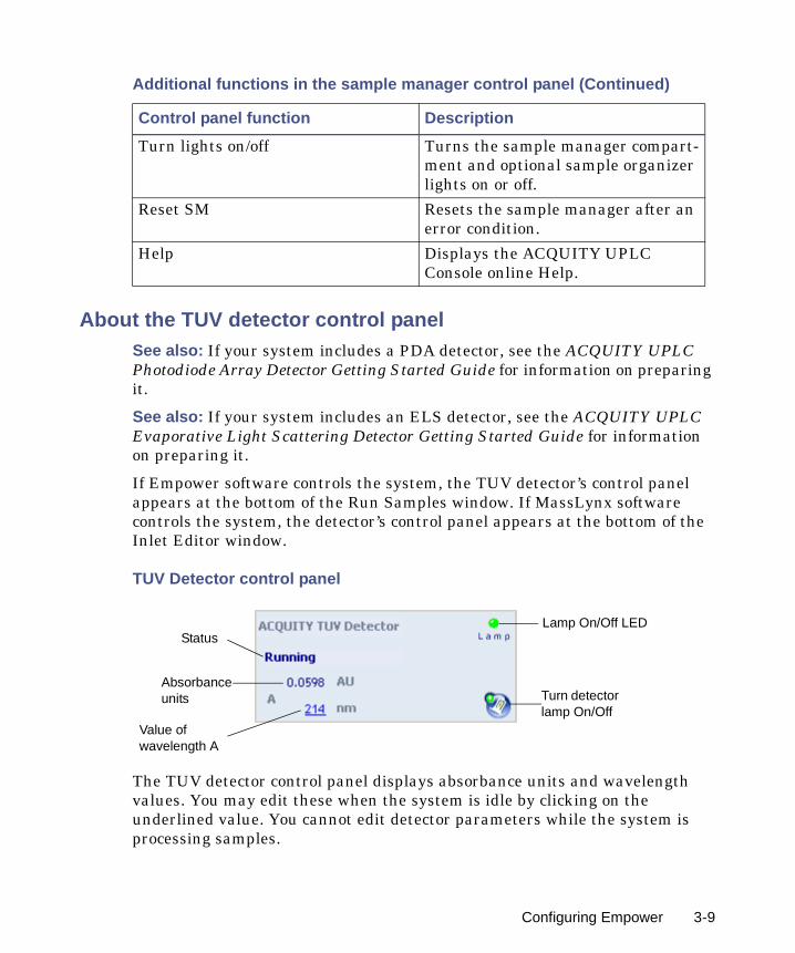
About the TUV detector control panelSee also: If your system includes a PDA detector, see the ACQUITY UPLC Photodiode Array Detector Getting Started Guide for information on preparing it.
See also: If your system includes an ELS detector, see the ACQUITY UPLC Evaporative Light Scattering Detector Getting Started Guide for information on preparing it.
If Empower software controls the system, the TUV detector’s control panel appears at the bottom of the Run Samples window. If MassLynx software controls the system, the detector’s control panel appears at the bottom of the Inlet Editor window.
TUV Detector control panel
The TUV detector control panel displays absorbance units and wavelength values. You may edit these when the system is idle by clicking on the underlined value. You cannot edit detector parameters while the system is processing samples.
Turn lights on/off Turns the sample manager compart-ment and optional sample organizer lights on or off.
Reset SM Resets the sample manager after an error condition.
Help Displays the ACQUITY UPLC Console online Help.
Additional functions in the sample manager control panel (Continued)
Control panel function Description
Lamp On/Off LED
Turn detector lamp On/Off
Status
Absorbance units
Value of wavelength A
Configuring Empower 3-9
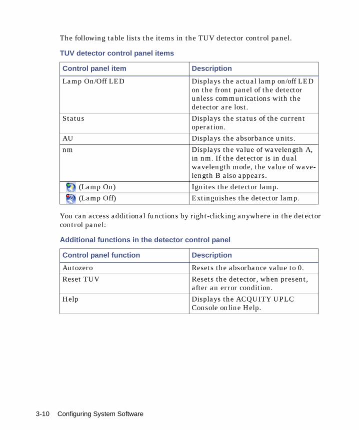
The following table lists the items in the TUV detector control panel.
You can access additional functions by right-clicking anywhere in the detector control panel:
TUV detector control panel items
Control panel item Description
Lamp On/Off LED Displays the actual lamp on/off LED on the front panel of the detector unless communications with the detector are lost.
Status Displays the status of the current operation.
AU Displays the absorbance units.
nm Displays the value of wavelength A, in nm. If the detector is in dual wavelength mode, the value of wave-length B also appears.
(Lamp On) Ignites the detector lamp.
(Lamp Off) Extinguishes the detector lamp.
Additional functions in the detector control panel
Control panel function Description
Autozero Resets the absorbance value to 0.
Reset TUV Resets the detector, when present, after an error condition.
Help Displays the ACQUITY UPLC Console online Help.
3-10 Configuring System Software
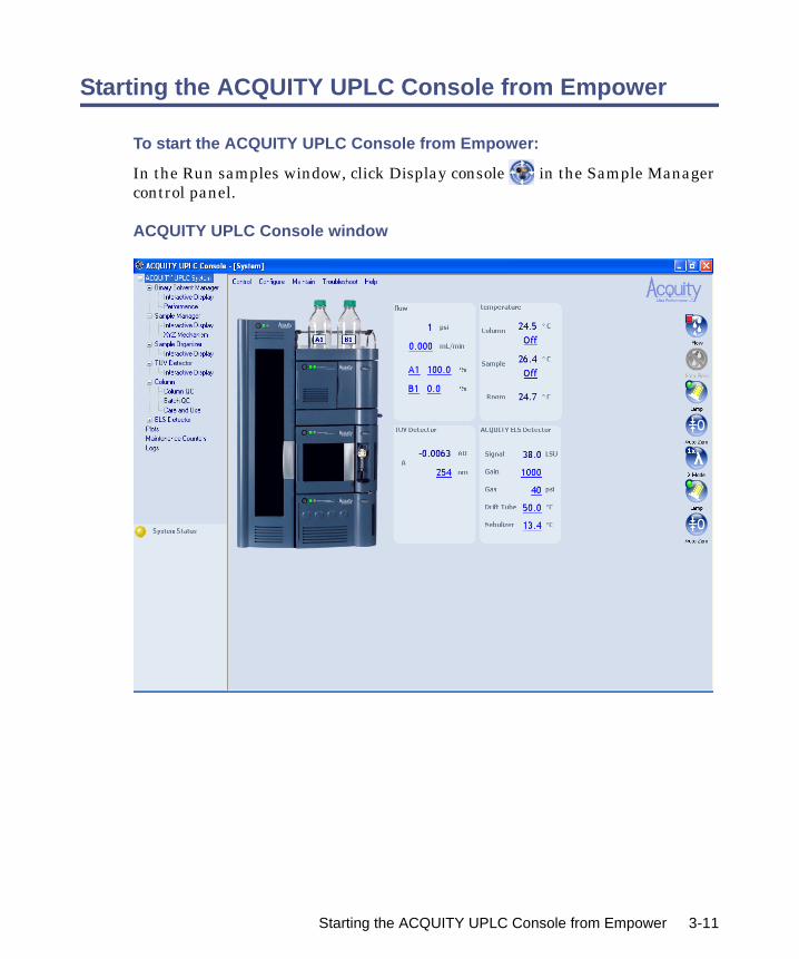
Starting the ACQUITY UPLC Console from Empower
To start the ACQUITY UPLC Console from Empower:
In the Run samples window, click Display console in the Sample Manager control panel.
ACQUITY UPLC Console window
Starting the ACQUITY UPLC Console from Empower 3-11

Configuring MassLynx software
Perform these tasks to configure MassLynx software:
• Start the application
• Select system instruments
To start MassLynx software:
1. Select Start > Programs > MassLynx > MassLynx.
Alternative: You can also start MassLynx software through the MassLynx desktop shortcut.
If MassLynx Security is not enabled, MassLynx software starts, and the MassLynx window appears. If MassLynx Security is enabled, the MassLynx Login dialog box appears.
2. Type your user name and password, and select your domain.
3. Click OK. The MassLynx window appears.
To select system instruments:
1. In the MassLynx window, click Inlet Method.
2. In the Inlet Method window, select Instrument Configuration from the Tools menu of the Inlet Method window.
3. In the Inlet Configuration window, click Configure and then click Next.
4. In the Select Pump dialog box, select Waters ACQUITY as the pumping device, and then click Next.
5. Select Waters ACQUITY as the autosampler, and then click Next.
6. Select Waters ACQUITY TUV, Waters ACQUITY PDA, or Waters ACQUITY ELS as the detection device, and then click Next.
7. Click Next.
8. Click Finish.
9. Click Finish, and then click OK.
10. In the Instrument Control Option Pack dialog box, ensure that “Install new instrument software or upgrade existing installation(s)” is selected, and then click Next.
3-12 Configuring System Software

11. Select ACQUITY Binary Solvent Manager, ACQUITY Sample Manager, and ACQUITY TUV Detector (or ACQUITY PDA Detector and/or ACQUITY ELS Detector), and then click Next. A progress bar appears at the bottom of the dialog box.
12. When the instrument control option pack installation is finished, the Results screen of the Instrument Control Option Pack dialog box appears.
13. Click Finish. The Inlet Method window appears.
Starting the ACQUITY UPLC Console from MassLynx software
To start the ACQUITY UPLC Console from MassLynx software:
1. In the MassLynx window, click Inlet Method. The Inlet Method window appears.
2. Click the ACQUITY Additional Status tab. The sample manager status appears.
3. Click Display console . The ACQUITY UPLC Console window appears.
Starting the ACQUITY UPLC Console from MassLynx software 3-13

3-14 Configuring System Software

4 Verifying System Operation
This chapter explains how to run a gradient performance test on a system with a TUV detector to verify that your system is operating properly. The sample you use to verify the system is included in the system startup kit.
Before you begin this procedure, your system must be set up and configured as described in the Waters ACQUITY UPLC System Operator’s Guide.
Tip: To ensure you have the latest version of this procedure, visit http://www.waters.com and click Support Center.
Restrictions:
• This gradient performance test is not applicable to ACQUITY UPLC systems that have a mass spectrometer.
• There is no gradient performance test for ACQUITY UPLC systems that have an ELS detector.
Contents:
Topic Page
Preparing the system 4-2
Creating the test methods 4-5
Performing the gradient performance test 4-9
4-1

Preparing the system
Preparation is the same whether the system is controlled by the Empower or MassLynx data system.
Requirements: Due to the increased sensitivity of the ACQUITY UPLC system and detectors:
• All solvents, including water and additives, must be of the highest chemical purity (MS-grade). Failure to use MS-grade solvents will result in high background concentration, low signal-to-noise, and loss of sensitivity.
• All MS-grade solvents used with the ACQUITY UPLC system should be properly filtered prior to their use. Waters recommends that the solvent be filtered through an appropriate membrane filter using a solvent clarification kit (47-mm all-glass filter holder with 1-L flask) immediately before use. A general-purpose laboratory vacuum pump is also required for use with the all-glass solvent filtration apparatus.
• Glassware (such as solvent bottles) should not be washed with detergents or washed with other general glassware to prevent contamination. The glassware should be rinsed with the high-purity solvents to be used.
See also: Controlling Contamination in LC/MS Systems (part number 715001307) on the ACQUITY UPLC System Bookshelf CD.
Waters recommends that mobile phases and wash solvents be mixed as follows:
• Mobile phase A1 - 10:90 acetonitrile/water (for A1, B2, strong and weak needle-wash, and the plunger-seal wash lines)
• Mobile phase A2 - 100% acetonitrile (for solvent line B1 and A2)
• Mobile phase B1 - 100% acetonitrile
• Mobile phase B2 - 10:90 acetonitrile/water
• Weak wash - 10:90 acetonitrile/water
• Strong wash - 10:90 acetonitrile/water
• Plunger seal wash - 10:90 acetonitrile/water
4-2 Verifying System Operation

To prepare the system for verification:
1. Prepare a 10:90 acetonitrile/water mobile phase:
a. Measure 100 mL of filtered acetonitrile into a 100-mL graduated cylinder.
b. Carefully transfer the acetonitrile to a 1-L reservoir bottle.
c. Measure 900 mL of filtered HPLC-grade water into a 1000 mL graduated cylinder.
d. Carefully transfer the water to the same 1-L reservoir bottle.
e. Cap the reservoir bottle and mix well.
f. Label the reservoir bottle as 10:90 acetonitrile/water.
g. Submerge lines A1, B2, plunger seal wash, strong needle wash, and weak needle wash in the reservoir bottle containing the 10:90 acetonitrile/water.
h. Place the reservoir bottle in the solvent tray.
2. Prepare a mobile phase of 100% acetonitrile:
a. Pour approximately 1L of filtered acetonitrile into a 1-L reservoir bottle.
b. Label the reservoir bottle as acetonitrile.
c. Submerge lines A2 and B1 in the acetonitrile reservoir bottle.
d. Place the reservoir bottle in the solvent tray.
Warning: Chemical exposure risk. Always observe safe laboratory practices when you use this equipment and when you work with solvents and test solutions. Know the chemical and physical properties of the solvents and test solutions you use. See the Material Safety Data Sheet for each solvent and test solution in use.
Preparing the system 4-3

3. Install the ACQUITY UPLC column in the column heater, close the column tray, and replace the column heater’s front cover.
4. Access the ACQUITY UPLC Console and perform these tasks:
a. Prime each solvent line of the binary solvent manager for 10 minutes. See “Priming a wetted binary solvent manager” on page 2-10.
b. Prime the seal wash of the binary solvent manager for several minutes. See “Priming a wetted binary solvent manager” on page 2-10.
c. Prime the sample manager at least 5 times. See “Priming the sample manager” on page 2-16.
d. Perform the seal characterization procedure in the sample manager. See “Characterizing the needle seal” on page 2-20.
e. Calibrate the system volume in the sample manager.
Alternative: Use the Refresh (Sys Prep) function to prime the binary solvent manager. See “Refreshing the system” on page 2-10.
5. Prepare the sample as listed on the sample instructions, using 10/90 acetonitrile:water.
6. Place the sample in the vial plate, noting the vial position, and put the plate in position 2 of the Sample Manager.
Caution: Never change directly between immiscible eluents or between buffered solutions and organic eluents. Immiscible eluents form emulsions in the flow path. Buffered solutions and organic eluents in combination can result in salt precipitation in the gradient proportioning valves, pump heads, check valves, or other parts of the system. Confirm that all fluids in the system are miscible with acetonitrile. If you need additional information about priming your system, see “Priming the binary solvent manager” on page 2-8.
4-4 Verifying System Operation
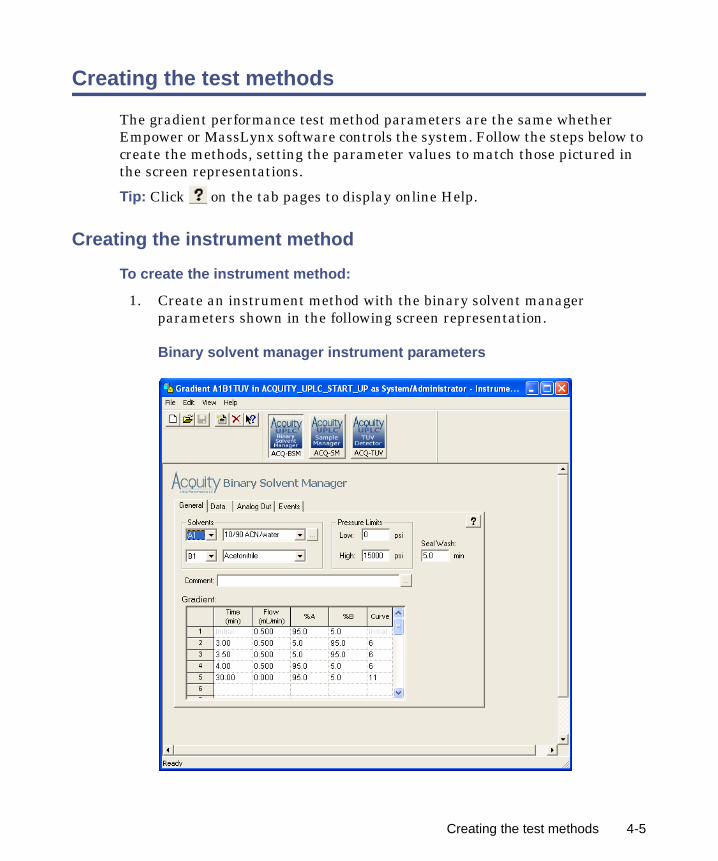
Creating the test methods
The gradient performance test method parameters are the same whether Empower or MassLynx software controls the system. Follow the steps below to create the methods, setting the parameter values to match those pictured in the screen representations.
Tip: Click on the tab pages to display online Help.
Creating the instrument method
To create the instrument method:
1. Create an instrument method with the binary solvent manager parameters shown in the following screen representation.
Binary solvent manager instrument parameters
Creating the test methods 4-5

Tip: The binary solvent manager parameters are the same regardless of whether your system includes the TUV or PDA detector.
2. Set instrument method parameters for the sample manager as shown in the following screen representation.
Sample manager instrument parameters
Tip: The sample manager parameters are the same regardless of whether your system includes the TUV or PDA detector.
4-6 Verifying System Operation
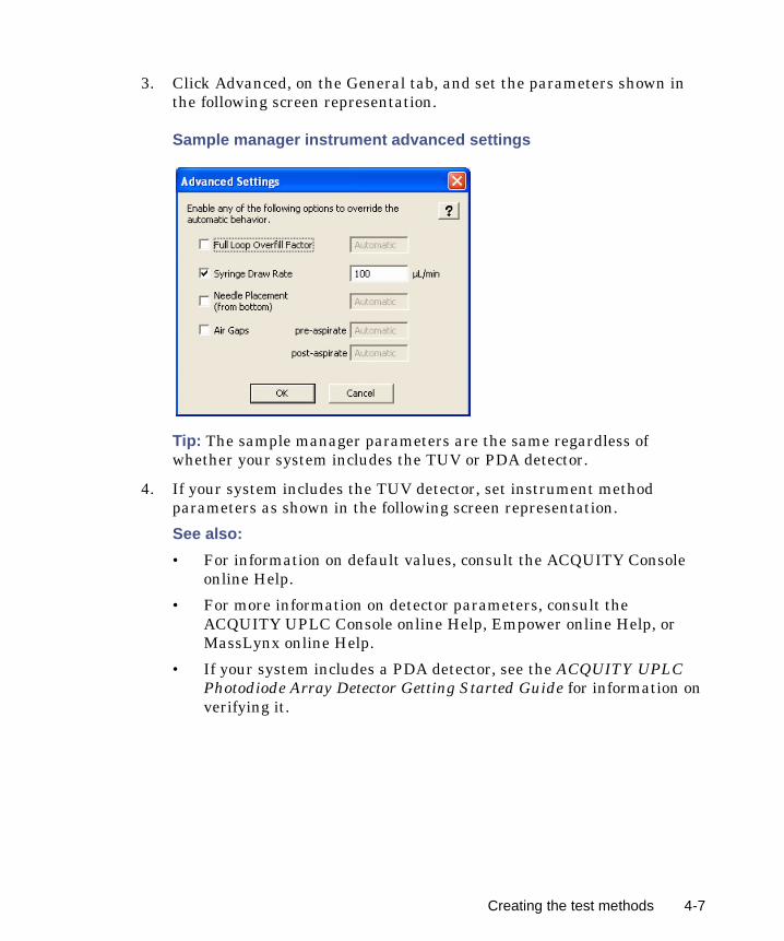
3. Click Advanced, on the General tab, and set the parameters shown in the following screen representation.
Sample manager instrument advanced settings
Tip: The sample manager parameters are the same regardless of whether your system includes the TUV or PDA detector.
4. If your system includes the TUV detector, set instrument method parameters as shown in the following screen representation.
See also:
• For information on default values, consult the ACQUITY Console online Help.
• For more information on detector parameters, consult the ACQUITY UPLC Console online Help, Empower online Help, or MassLynx online Help.
• If your system includes a PDA detector, see the ACQUITY UPLC Photodiode Array Detector Getting Started Guide for information on verifying it.
Creating the test methods 4-7

• If your system includes an ELS detector, see the ACQUITY UPLC Evaporative Light Scattering Detector Getting Started Guide for information on performing a run.
TUV detector instrument parameters
5. Save the instrument method.
Creating the sample set methodIf Empower software controls the system, you must create a sample set method. The sample set method parameters (Inj Vol., # of Injections, Function, Run Time, and Next Injection Delay) are the same whether your system includes the TUV or PDA detector. However, the method set and report methods vary. Before acquiring data, ensure that you chose the appropriate method set.
4-8 Verifying System Operation
See also: For more information on creating a sample set method, consult the Empower online Help.
To create the sample set method:
1. Set these sample set method parameters:
• Condition column once (run time = 6.0 minutes)
• Injection volume = 5 µL (10 mm, 25 mm flow cell or ELSD)
• # of Injections = 3
• If Empower software controls the system, run time = 4.0 minutes (with Next Injection Delay = 2.5 minutes). If MassLynx software controls the system, total run time = 6.5 minutes
2. Save the sample set method.
Performing the gradient performance test
Restriction: If your ACQUITY UPLC system uses only a mass spectrometer, the gradient performance test is not applicable.
When the system is prepared and the test methods are created, you are ready to perform the gradient performance test. The steps for running the test vary slightly, depending on whether your system uses Empower or MassLynx software, but the desired results are the same.
To perform the test:
1. Start the run:
• If the system is controlled by Empower software, open the project in Run Samples, select the gradient performance test sample set, and then select Run and Report.
• If the system is controlled by MassLynx software, access the MassLynx main page, and select Start from the Run menu.
Performing the gradient performance test 4-9

2. When the sample set is complete, enter the appropriate results in the table, below.
3. Review the gradient performance report. The gradient performance test result is “passing” when these conditions are realized:
• The peaks are symmetrical, integrated, and identified correctly. (Compare the chromatogram on the report to the sample chromatogram, below, to determine this.)
• The peak retention times show a standard deviation of less than or equal to 2.0 seconds. (Consult the table you completed to determine this.)
Retention time reproducibility (three replicates)
PeakPeak retention time mean value
Std dev Acceptable std dev
2-acetylfuran ≤1.5 secs
acetanilide ≤1.5 secs
acetophenone ≤1.5 secs
propiophenone ≤1.5 secs
butylparaben ≤1.5 secs
benzophenone ≤1.5 secs
valerophenone ≤1.5 secs
4-10 Verifying System Operation
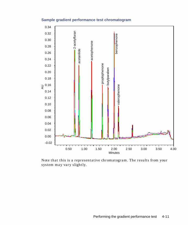
00
Sample gradient performance test chromatogram
Note that this is a representative chromatogram. The results from your system may vary slightly.
0.34
0.32
0.30
0.28
0.26
0.24
0.22
0.20
0.18
0.16
0.14
0.12
0.10
0.08
0.06
0.04
0.02
0.00
-0.02
0.50 1.00 1.50 2.00 2.50 3.00 3.50 4.Minutes
AU
2-ac
etyl
fura
n
acet
anili
de
acet
ophe
none
prop
loph
enon
e
buty
lpar
aben
benz
ophe
none
vale
roph
enon
e
Performing the gradient performance test 4-11

4-12 Verifying System Operation


