and eliminate the cost and need for: • Combustible, rot prone plywood forms. • A myriad of transmission paths through closely spaced supports. • Moisture retaining fiberglass infill that plugs sub-drains and encourages vermin. while gaining: • An easier, lower frequency isolation method. • A positive air gap. • A floor supported by Mason Low Dynamic Stiffness Rubber– the time tested, low frequency, exposure-proof and truly structural material, at lower cost. When you need a floating floor to dramatically Increase your Sound T ransmission Class and Impact Noise Rating Our Riverbank Test Data demonstrates that a four-inch thick concrete floor floating on neoprene mounts improves the STC by 25 if raised two inches and that the INR goes up by 44... Tests using our lower frequency LDS mounts would add to these tremendous improvements. Remember, the air gap is the isolator, the jack-screw lifts the floor to achieve it, and the resilient LDS element supports the weight while working in parallel with the air. Mason Industries originated this system in 1965. Why not work with the company that created the idea and has thousands of successful installations? 1" to 4" Air Gap BULLETIN ACS-102-3.1 MASON JACK-UP FLOOR SLAB SYSTEM MASON INDUSTRIES, Inc. International Manufacturers of Shock, Seismic and Vibration Control Products, Acoustical Floor Systems, Building Isolation, Rubber Expansion Joints for Piping and Stainless Steel Hoses Why not use the
Transcript
and eliminate the cost and need for:• Combustible, rot prone plywood forms.
• A myriad of transmission paths throughclosely spaced supports.
• Moisture retaining fiberglass infill that plugssub-drains and encourages vermin.
while gaining:• An easier, lower frequency isolation method.
• A positive air gap.
• A floor supported by Mason Low DynamicStiffness Rubber– the time tested, lowfrequency, exposure-proof and trulystructural material, at lower cost.
When you need a floating floorto dramatically Increase yourSound Transmission Class andImpact Noise Rating
Our Riverbank Test Data demonstrates that a four-inchthick concrete floor floating on neoprene mounts improvesthe STC by 25 if raised two inches and that the INR goesup by 44... Tests using our lower frequency LDS mountswould add to these tremendous improvements.
Remember, the air gap is the isolator, the jack-screwlifts the floor to achieve it, and the resilient LDS elementsupports the weight while working in parallel with the air.
Mason Industriesoriginated thissystem in 1965.Why not work withthe company thatcreated the ideaand has thousandsof successfulinstallations?
MASON INDUSTRIES, Inc.International Manufacturers of Shock, Seismic and Vibration
Control Products, Acoustical Floor Systems, Building Isolation,Rubber Expansion Joints for Piping and Stainless Steel Hoses
Business Card Logo
Why not use the
2
Letter to the Architect 2Technical Information & Tests 3Concrete Floating Floor Discussion 4 & 5Replacing Neoprene with LDS 6LDS Jack-up Specifications 7 – 12
We have been floating floors, resiliently suspending ceilings and isolating walls for closeto 45 years. The need for this acoustical reinforcement has been well established in text-books, sales literature and acoustical engineering recommendations. Therefore, wethought it would be helpful to offer a handbook of specific methods and suggested spec-ifications rather than just print another interesting but rather general brochure.
1. There are basically two methods of reducing airborne sound transmission. The first isto increase the mass of the walls, floors or ceilings and the second is to introduce an air gapbetween relatively airtight constructions.
2. When dealing with a monolithic building component such as a solid concrete floor dou-bling the mass raises the STC by a maximum of 5. Actual test results are shown graphical-ly on page 3. Because of this it becomes impractical to rely on mass alone as a 6” solidconcrete floor has an STC of 54. Doubling to 12” raises the STC to 59. Doubling again toan unacceptable 24” raises the STC to only 64.
3. Once you decide on the maximum practical weight for the construction the next acousti-cal step is to split this mass into two components sandwiching an air gap. This air gap trig-gers a tremendous improvement in STC as shown by the Riverbank Tests of a floating floorwith flanking protection. (Test Two, page 3.) Notice that the addition of a 4” concrete pouron the original 6” raised the STC from 54 to only 57. The introduction of a 2” air gap betweenthese sections raised the STC to 79 for a dramatic improvement of 22. Increasing the airgap to 4” raised the STC to 82. Doubling the air gap raises the STC a theoretical 5, but theactual result is more like 3 because of resonances.
4. The introduction of lightweight fiberglas in the air space between massive structural ele-ments such as concrete floors or walls is expensive and unimportant. The experimentalinclusion in a 2” void increased the STC by 3 beyond the original 79. (Test Two, page 3.)This is meaningless at these levels as the 79 is all but unattainable in a commercial struc-ture because of flanking. Fiberglas is an important addition over suspended ceilings, how-ever, where the mass is light and the contribution noticeable.
5. The air gap is the isolator. The purpose of the vibration mounting is to provide structur-al support without voiding the air gap. Since each mount is a potential transmission path, itis logical that the fewer mounts or support points, the better the chance of protecting andnot bypassing the air gap.
6. Specifications should be written by the professional for the protection of the client andnot the protection of the vendor. Specifications should emphasize performance characteris-tics, physical properties and construction rather than manufacturing techniques. In describ-ing a steel spring it would be unimportant whether the steel was produced by the Bessemeror Open Hearth method. The molder need not be told the proper curing temperature or car-bon black particle size and certainly, the glass people know the specific technique for man-ufacturing fiberglas. It would be important in specifying steel springs to keep the operatingstresses well within the elastic limit; to describe rubber mounts in terms of tensile strength,permanent set, elongation, compression set, etc. A proper dialogue regarding fiberglaswould similarly cover permanent set, dynamic frequency and most importantly waterproof-ing tests of this sensitive material that fails when wet.
7. All vendors tend to favor their own products rather than those of their competitors. Asopposed to this, an acoustical expert studies all of the available materials and recommendswhat in his unbiased judgment is best for the application. If there is no such person withinyour own organization, we continue to suggest that you retain an outside acoustical con-sultant to help you in this most critical field of client sensitivity.
We would appreciate your comments as to subjects not covered, our method of presentingthis information or any other suggestions to make this booklet more valuable to yourselvesand other people in the architectural and acoustical disciplines.
Very truly yours, MASON INDUSTRIES, INC.
Mason 4” Thick FSN Floating Floor Tests conducted at theRiverback Acoustical Laboratory in March and June of 1971.
Effects of 0, 1”, 2”, 3” and 4” Air Gaps on STC & INR.Business Card Logo
3
FIRST TEST MARCH 1971 OF A FLOATING FLOOR ONLY.DISAPPOINTING RESULTS BECAUSE OF FLANKING PROBLEMS
SECOND TEST JUNE 1971 OF SAME FLOATING FLOOR WITHISOLATED WALLS AND CEILING TO PREVENT FLANKING
Riverbank TL-71-152 March 71 Riverbank TL-71-247 June 71
Riverbank TL-71-152 March 71 Riverbank TL-71-247 June 71
*While the use of infill raises the STC an additional 3 in a 2” air gap, wefeel it is overkill as field flanking will prevent achieving the higher value.The floating floor @79 STC is already the most sound resistant path.
FIRST TEST DATA IN BROWN, SECOND TEST DATA IN BLACK FIRST TEST DATA IN BROWN, SECOND TEST DATA IN BLACK
SOUNDSOURCEROOM
STANDARD MASS/STC LIMP MASS LAWPREDICTION AND TEST DATA
Concrete floating floors are used for many purposes. We have limited this bulletin to the following areasof Vibration, Sound and Impact Isolation.
1. VIBRATION ISOLATIONBuildings are unavoidably near busy streets, trains and subways even though they contain space thatmust be vibration free and have very low NC levels. Examples include television studios and theatresand in some cases sound test rooms located in the center of factories.The frequency of the isolator supporting these floors is normally determined by the architect or anacoustical consultant depending on the input frequencies. Within our range of experience we recom-mend LDS mountings with a dynamic frequency not exceeding 10 Hz for input no lower than 20 Hzproviding frequencies below 30 Hz are limited in amplitude. Steel spring isolators come into their ownwhen the input is more severe or below 20 Hz. The required deflection of the springs is dependent onthe input frequency, but most spring floating floor work is done with deflections between 0.5” and 0.75”to provide frequencies in the 4.5 to 3.6 Hz range. When heavy impact is a major factor, springs arealways required.We have provided LDS isolators to reduce subway vibration at grade. They were very effective as thelowest input frequency was measured at 20 Hz and the ground amplitudes were small. In another application, however, television studios were located on the third floor of an old building. Springmountings were specified by the same acoustical consultant as the upper floor amplitudes were highand frequencies low, not only because of motor truck traffic outside the building, but the passage ofheavy scenery wagons in halls between studios.
2. SOUND ISOLATIONTypical of these applications are the introduction of floating floors in very noisy equipment rooms locat-ed over prime office space or floating roofs as a protection against aircraft noises.Since we are dealing with the prevention of airborne noise transmission only, LDS mountings arealways the choice. The lowest audible frequency is about 25 Hz so there is no need for mountings ofgreater deflection. Spring mountings manufactured with LDS materials in series with the springs wouldwork equally well in this application, but they are needlessly expensive. Since the floating floor’s fre-quency is too high to isolate machinery, the only function is the prevention of airborne sound trans-mission. Machinery supported on the floating floor must have steel or air spring isolators.
3. IMPACT ISOLATION Examples of straight impact isolation would normally include kitchens, weight rooms or bowling alleys.A commercial kitchen in an office building generates structurally transmitted noise. The noiselevel within the kitchen itself might not be very high, but the rolling of carts, the dropping of dishes,the rattling of cutlery on steel tables, the placing of pots on stoves, etc., all represent impact andmechanically transmitted sound. LDS isolators have been effective in most of these applications butsprings are better.Where gym floors are the problem and we must deal with running, jumping and bouncing balls, LDSwould be effective over a very rigid substructure, but once again springs are the safer approach.
JACK-UP (Lift-Slab) SYSTEMWe believe that the most fool-proof and safest way to establish the air gap is the jack-up or lift-slabmethod. Plastic sheeting is placed on the sub-floor as a breaker layer, isolators are placed on the plas-tic sheeting, reinforcing steel or mesh rests on the isolator housings, and the concrete floor is poured.After the concrete has cured, the slab is lifted to elevation by turning adjustment bolts above each iso-lator to any specified air gap between 1” and 4”.
FORM-WORK SYSTEMThe alternate, almost obsolete, method is one whereby a continuous layer of the isolation media isused as a pouring surface. More commonly, individual isolators, the thickness of the air gap are placedin position in the field and covered with plywood or factory attached to plywood before delivery. Theupper surface is covered with a plastic layer and then the reinforcing is placed on top of the plywoodforms and the concrete poured at finished elevation.
MACHINERY SUPPORTIn our older publications we advocated the support of heavy machinery on full sized structurally sup-ported pedestals or individual structurally supported pedestals as shown in the illustrations on page 5.While the performance of systems installed that way was excellent, it proved to be a major coordina-tion problem because the pedestals had to be located, poured and anchored to the sub-floor before thesystem could go ahead. There was very little saving in cost as we provided isolators around the edgesof these pedestals so there was no saving in the number of isolators. There was the additional laborof installing perimeter board and caulking. We gradually modified our approach to using this methodfor only the heaviest of machinery such as chillers, but based on our continued experience we are nowsuggesting continuous floating floors with all the housekeeping pads and equipment on top.
JACK-UP VERSUS FORM-WORK METHODWhen the form-work method is used, the spacing of the mountings is a function of the stiffness of theforms which support the wet concrete. In using half inch plywood, which is the most common form, wehave tested 12”, 16” and 24” spacing. We have found 24” spacing to be highly satisfactory. Closerspacing merely means more fussing with light capacity mountings and in comparing 12” with 24” spac-ing the introduction of four times as many transmission points.Our development of the lift-slab method accelerated in 1962 when we isolated some 30,000 squarefeet of television studios for CBS using jack-up spring mountings. The mountings were designed to theperformance specifications of an acoustical consultant. This new method was an immediate success.
When using the lift-slab technique, the spacing of the isolators is determined by the thickness of thefloating floor and the reinforcement. When 4” slabs are used, a spacing of 54” in both directions iswell within design limitations. Thus we have 1/20 the number of transmission pads offered by a formwork or panel system using 12” spacing. Thicker slabs allow for wider spacing and 60” or more is notunusual.
SOUND
JACK-UP FLOORRecommended Spacing 54”
IMPACT
SPRINCONCRETE FLOATING FLOORS discussion
VIBRATION
Business Card Logo
1" to 4"Air Gap
5
Structural tests run in 1974 indicate that 48” spacing using 6x6x10 gauge mesh 1” from the bottom isa very safe system for live loads of 150 Lbs. per square foot, or rolling loads of 350 Lbs. per lineal foot.Rolling loads must be considered when rigging machines into place. These allowable loadings werederived from destruction tests, and based on a 3 to 1 safety factor. The full certified Jones Test Reportis available on request. Extremely heavy concentrated loads are accommodated by isolators directlyunder the loads or by using heavier local reinforcing to carry the load to mountings paralleling theequipment. Heavier reinforcement allows greater spacing.
The most advantageous way of using the jack-up system is to roll the heavy equipment into positionbefore the floor is raised, so there is no danger of cracking the areas of lighter capacity as the machin-ery rolls by. The floors are raised with the machinery in place. When it is done this way, all mountingshave the most uniform deflection. While this is the ideal way, the concrete people usually want to beoff the job and the machinery is placed after the floor is raised. This is no problem either, as a liftedfloor is no different than a floor poured at elevation.
In thinking about longevity it seems to be a contradiction to use plywood as the form in series with theisolator. If moisture is present, even exterior plywood will eventually rot. Plywood between floors is afire hazard that violates many state codes and fireproof plywood is very expensive. Why worry aboutthese problems when the plywood can be omitted with the jack-up system?
When deformed metallic forms are specified, many of these objections no longer exist as in one direc-tion the support mountings can be moved out to the larger centers. Fire and rotting is similarly no longera problem. However, very few floors are installed this way as steel forms are expensive and difficult toinstall, particularly in odd shaped rooms.
We have omitted the use of lightweight fiberglas infill in all of our recommendations, because theacoustical improvement is negligible as shown in paragraph 4 of the opening letter on page 2. Whenwater is present between floors, the breakdown of the lightweight fiberglas tends to clog drains and tohold and carry moisture up to the plywood. This accelerates rotting whether the drains are introducedin the sub-floor or not.
The jack-up system is easier to install since there is no need to fit unusual contours. The mountingsare placed in position along the edges and the concrete flows to or around the odd shapes. Any air gapup to 4” can be used at no increase in cost. Perhaps the most important point is that there is no pos-sibility of short circuiting of the air gap by concrete spills between plywood panels. When these acci-dents happen, there is no way to tell until the floor does not perform properly. In effecting repairs youmust first locate the short circuit, break or cut out that area of the floor, somehow re-establish the rein-forcing by welding or tying to the stubs that are left and then repouring the patch. This can never hap-pen with a lift-slab system as the floors are lifted after the concrete has hardened so the air gap mustbe clear.
When using the jack-up system, the isolator is within the cast iron housing, so the thickness of the iso-lator remains 2”, even if the floor is only elevated 1”. If you try to save height with a plywood system,the thickness of the isolator must be reduced with a loss in efficiency because the isolator frequencyincreases. We have installed floors that are 3” thick with a 1” lift for a total height of 4”. A plywood sys-tem with the same isolator frequency would have to be 51/2” high minimum. The 11/2” height savingcan be important.
While we prefer the lift-slab system, we have also included specifications using plywood forms as thereis the occasional application where the forms are practical or for reasons of your own you prefer thisolder technique.
EXTREME TRANSIENT LOAD CONDITIONS
Floating floors are sometimes subject to extremely hightransient loads that would deflect the floor beyond struc-tural limits and result in floor failure. Typical of these arestage floors, floating streets, convention exhibit centersand major production TV studios. Temporary loadingsare buses, trailer trucks or lift trucks with concentratedloads as high as 10,000 lbs. in any location. These prob-lems are handled with stop screw isolator designs. Themain adjustment bolt is enlarged to a threaded brassbushing with a centered steel bolt set to a predeter-mined clearance above a secondary base isolation plateand isolation pad. Let us discuss these specializedapplications with you as each problem is different.
SEISMIC CONSIDERATIONS
In seismic zones the peripheral walls or curbs must be studied and designed to withstand horizontalfloating floor displacement at the maximum acceleration in the area. Typically a 5,000 square foot floorwould weigh 250,000 Lbs. and the weight of any equipment attached to the floor would have to beadded to that. If the system were in a 0.5g zone, the lateral force would be 125,000 Lbs. Assuming thedimensions were 50 ft. x 100 ft., the 50 ft direction would be most critical and the curb or perimeter walldesigned to resist 2500 Lbs. per linear foot.
Another potentially serious problem is the curling and failure of the concrete floor from the forces intro-duced by the machinery restraints that must be anchored to the floating floor. The problem becomesapparent when you visualize a tall, narrow chiller. Acceleration at the center of gravity creates an over-turning moment that pulls on the floor on one side and depresses it on the other. A 4” concrete floorhas little inherent resistance to this type of bending and we have addressed this problem with a dou-ble acting resilient floor snubber type SFFS as illustrated on page 8 and 14.
The snubber is anchored to the sub-floor and the housing cast into the floating floor. The up and downclearances are adjusted after the floor has been raised. The floor restraints are grouped near the pointsof tension and compression or on either side of the housekeeping pads. The inclusion of these snub-bers keeps the floor captive and prevents damage. The generous clearances prevent short circuiting.We believe we are the first, if not the only company, to offer this engineering development.
IMPROVED PERFORMANCE BY REPLACING NEOPRENEWITH LDS (Low Dynamic Stiffness) RUBBER
Business Card LogoWe started Mason Industries in 1958. Our revolutionary
designs of high deflection free standing spring isolators, asopposed to housed mountings, and our literature with down toearth information made its mark. This generated phone callsfrom acoustical consultants asking us to get into the floatingfloor business. We asked why. In addition to wanting more thanone source, the implication was that some competitive infor-mation was unreliable and they would rather work with us.
In those wonderful days we were doubling our volume everyyear and keeping up with demand and continued developmentof our mechanical systems, led us to answer, we simply werenot ready to enter the floating floor market.
In 1965 one of our representatives ordered Bridge BearingNeoprene Pads. While we had been molding rubber for years,we were not familiar with this specification.
DuPont manufactures Neoprene, and they were a great help.In addition to the Bridge Bearing formulations, they providedpublications and back up information on Neoprene’s excellentaging characteristics.
After this exposure to Neoprene, we realized we had a properfloating floor material. If Neoprene could survive in outdoorapplications, exposed to sunlight, temperature extremes, snowand rain, it would certainly last for the life of the structure whenlocated in the dark, cozy, moderate temperature environment,under a floating floor. We immediately phoned the acousticalconsultants, and asked what frequency they needed
We were told they wanted an isolation frequency of 8 Hz in a2” air gap. Since the lowest audible frequency is 25 Hz. 25/8provided an acoustical ratio of 3/1, similar to minimum vibra-tion isolation, and at the higher frequencies, sound loss wouldimprove dramatically.
We learned that rubber materials are often deflected 10% ofthe rubber thickness, and many publications refer to 15%deformation as a good conservative compression limit. That iswhy our 2” thick isolators have published deflections of 0.2”and a maximum of 0.3”.
Dynamic Stiffness is simply defined as the ratio between thespring rate in vibratory motion and the static spring rate.
When working with steel springs, the ratio is 1, as spring steelis a completely resilient material. Rubber materials are quitedifferent. Dynamic stiffness increases with hardness and inbroad terms, the filler ratio of the materials to the rubber con-tent as well as the type of carbon black reinforcement, plasti-cizers, etc. It is also very sensitive to the polymer.
We ran our Kodaris Neoprene Dynamic Stiffness test in 1972.The corrected data showed that at 0.2” deflection, the poorestsituation using 60 duro with a dynamic stiffness of 1.63increased the frequency to 9 Hz at 0.2” and 7.3 Hz at 0.3” ascompared to a steel spring where 0.2” deflection would be 7 Hzand 0.3” 5.7 Hz.
In negotiating a recent building support project, we convincedthe client that Neoprene should be used in place of NaturalRubber. We were not concerned that the specification requireda new dynamic stiffness test, because we believed the Kodaristest data showing our 50 durometer Neoprene compound hada dynamic stiffness of 1.50 and 60 durometer 1.63. However,the dynamic stiffness tests run today are very different, and
much more sophisticated. It is a forced frequency test for res-onance at specific frequencies of 5, 10 and 15 Hz. We weredismayed to find that rather than 1.5 to 1.63, the new resultsranged from an average of 1.8 for 54 durometer to 2.4 for 64.Using the same test techniques, our new LDS rubbercompounds are below 1.3 in 50 durometer and 1.35 in 60.This meant the continued use of Neoprene represented toogreat a sacrifice in performance.
LDS stands for Low Dynamic Stiffness. In addition to exceed-ing all AASHO Bridge Bearing structural requirements, we hadworked for years to develop compounds with extremely LowDynamic Stiffness characteristics even in 60 and 70 durome-ter as published. Using these compounds lowers frequencyresponse for a given deflection to improve both vibration isola-tion and reduce sound transmission. Other than oil resistance,Mason LDS compounds are far superior to Neoprene in phys-ical characteristics as well. Building Support Pads can have alower profile than Neoprene for the same frequency. This istrue of floating floor mounts too, but mounting heights are oftenmaintained to achieve a specified air gap.
In Europe, virtually all isolation work was and is done withNatural Rubber. In this country, specifications for bridgebearing rubber supports allow the use of Neoprene or NaturalRubber. The very great majority of bearings, if not all, areNatural Rubber. However, there is no requirement for alow dynamic stiffness, so the compounds are made less expen-sive by using more fillers and are considerably lessefficient than our designs acoustically. In supporting bridges,this is unimportant as bearings are used in shear to accommo-date expansion and contraction and not for vibration isolation.
There is a mechanical aspect too. Most engineers andarchitects are in the habit of pouring concrete on forms withthe bearings directly underneath or erecting steel directly onthe bearings. In this first stage, the loadings are very low sothe bearings hardly deflect. As the building progresses, thebearings deflect in response to the added weight, which is notalways uniform. The more deflection required to achieve a fre-quency, the greater the complication of uneven deflections thatmay distort the structure or induce cracks. LDS compoundsminimize that problem, because deflections are minimal for thesame frequency.
The use of Natural Rubber has been guided by the MalaysianRubber Institute, and just as DuPont has been promotingNeoprene and other excellent special purpose polymers, theNatural Rubber industry has been working with the chemicalpeople to perfect the antiozonants and antioxidants. Otheradditives reduce sunlight damage. The new Natural Rubbermaterials have become completely reliable in long term agingtests, so there is no longer any reason to continue with theNeoprene. We have always improved our offerings, and hope-fully, our learning curve will continue.
Based on these conclusions, all acoustical isolation materials,including the mounts used in Jack-up systems, the EAFMseries, or bearings to support and isolate structures will bemade of LDS materials. (Low Dynamic Stiffness.) Hangerelements and hanger cups are included as well.
While the danger of oil contamination is minimal, all floormounted pads under spring isolators, spring holders, etc., willcontinue as commercial grade Neoprene.
The following floor specifications are all written in the format of the“United States Construction Specifications Institute”. All specifica-tions are available upon request on CD Rom.
LDS JACK-UP SYSTEM FOR MECHANICAL EQUIPMENT ROOMSWITH MACHINERY SUPPORTED BY THE FLOATING FLOOR.
PART 1 - GENERAL
1.01 Description
A Scope of Work
1. Isolate floating floors from building structure by means of jack-upLDS isolators and perimeter isolation in each of the mechanicalequipment rooms as shown on the drawings.
If sound barrier walls are used, add the following:
2. Build sound barrier walls on the floating floors.
B. Substitution of Materials
1. Substitute materials shall meet or exceed the “quality” of the prod-
MECHANICAL EQUIPMENT ROOM LDS JACK-UP SYSTEMbeginning of specifications
JACKED UPFLOATING
FLOOR
POURING OFCONCRETE
PLACEMENTOF ISOLATION
MATERIALS
GROUT TOPSOF ISOLATORS
CAULK
SPECIFIEDAIR GAP
ISOLATEDFLOOR DRAIN
STRUCTURALFLOOR
POLYETHYLENE
SHEETINGREINFORCING FSN
CASTINGS
POURED CONCRETE ISOLATOR
RUBBER PLUGS
ISOLATION
FLOATING FLOORCONSTRUCTION
SEQUENCE
Business Card Logo
CAULKED PERIMETER
ISOLATION BOARD
Type CFDA4 x 4FLOOR DRAIN
Type FSNLDS JACK-UP MOUNT
EQUIPMENTHOUSEKEEPING PAD(must be mechanicallysecured to floating floorin seismic zones.)
8
ucts which are listed in these Specifications. Submit samples andtest reports by an independent laboratory for consideration on thisproject.
1.02 Design
A. Intent
1. The floating floor system shall consist of a 4”(100mm) thick con-crete slab isolated from and supported 2”(50mm) above the water-proofed structural slab by resilient LDS isolators within cast ironhousings designed to jack up the floor after pouring on the sub-floor.
If sound barrier walls are used, add the following:
Sound barrier walls consisting of 6”(150mm) filled concrete block(Barrier wall construction can be changed when writing specifica-tion) shall rest on the floating floor with a 31/2” air gap to the struc-tural walls. (31/2”(90mm) may be reduced to 2”(50mm) if no swaybraces are needed.)
2. The floating floor slab shall be isolated from adjoining walls,columns and curbs by means of perimeter isolation.
3. Any floor drains, piping, conduit and duct penetrations must notshort circuit the isolation system.
4. Any equipment within these rooms shall be mounted on house-keeping pads or directly on the floating floor as shown on the draw-ings.
5. In seismic zones the floating floor shall be restrained horizontally bycurbs or walls designed to withstand the horizontal seismic forces.Solid bridge bearing LDS pads shall be interspersed betweenperimeter isolation to withstand the seismic forces with a maximumdeflection of 0.2”(5mm). When perimeter cannot be used for seis-mic constraint, intersperse horizontal restraints within floor system.
6. In seismic zones 2, 3 and 4 or equivalent Av, the floor shall be pro-tected by embedded double acting resilient floor snubbers set inopposition to the overturning moments at the equipment snubbersin all locations where the center of gravity of major equipment ishigh.
B. Performance Requirements
1. The floating floor system shall have a minimum rating of STC-79and INR+17 as verified by an independent laboratory in prior tests.
C. Floor System Construction Procedure
1. The setting of all isolation materials and raising of the floor shall beperformed by or under the supervision of the isolation manufactur-er.
2. Set and waterproof any drains and lower pipe seals in keeping withwaterproofing specifications.
3. Cement perimeter isolation around all walls, columns, curbs, etc.
3a. In seismic zones intersperse the perimeter isolation with bridgebearing quality LDS pads the thickness of the perimeter isolation orbolt to the sub-floor.
4. Cover entire floor area with 6 mil (0.15mm) plastic sheeting andcarry sheeting up perimeter isolation.
5. Place bell-shaped castings on a maximum of 54”(1370mm) centersin the general areas in strict accordance with the approved draw-ings prepared by the isolation manufacturer. Spacing can beincreased to straddle machinery locations. Additional reinforcementmust be detailed on isolation manufacturer’s drawings whenrequired.
If sound barrier walls are used, add the following:
Perimeter isolators shall be selected to support the wall weight inaddition to the perimeter of the floating floor.
5a. In seismic zones attach double acting resilient seismic snubbers tothe structural slab on either side of high center of gravity equipmentto withstand the overturning moment generated by the machinerysnubbers and prevent failure of the floating floor.
6. Place reinforcing as shown on the drawings and pour floor mono-lithically.
7. Raise floor 2”(50mm) by means of the jack-screws. (If constructionsequence dictates raising the floor before placing machinery, heavyplanking must be used to protect floor while machinery is beingrolled into position).
8. Caulk perimeter isolation in all locations and grout jack-screw holes.
If sound barrier walls are used, add the following:
9. Construct block walls on the floating floor being careful that mortardoes not drop behind the walls. Place 2”(50mm) fiberglass batsagainst the structural wall as a precaution. Provide sway braces andisolated angle iron wall braces at the top of the walls. Caulk angleiron braces.
10. In seismic zones adjust the double acting snubbers after machineryis in place to provide a maximum up and down clearance of0.125”(3mm).
D. Submittals
1. Detailed product drawings and Load/Deflection curves of all isola-tors, double acting floor snubbers and/or other snubbing restraintswhen required.
2. AASHTO Test Reports on all properties in table 2.01 A from anaccredited independent laboratory for all rubber durometers used.
3. Dynamic stiffness test from an accredited independent laboratory at5, 10 and 15 Hz, showing dynamic stiffness does not exceed 1.4.
3a. Isolation frequency not to exceed 9 Hz at stated deflection.
4. Acoustical test data from an independent laboratory showing a min-imum STC of 79 and a minimum INR of 17 using a 4”(100mm) con-crete floating floor, a 6”(152mm) structural floor and a 2”(50mm) airgap.
5. A drawing or drawings showing:
a. Dead, live and concentrated loads.
b. Isolator sizes, deflections, frequencies and locations and in seis-mic zones, locations of seismic snubbers.
If sound barrier walls are used, add the following to b:
Wall sway brace and isolated angle iron brace sizes, locationsand frequencies.
c. Any drain and penetration locations.
d. Size, type, elevation and spacing of concrete reinforcement.
e. Caulking details.
f. Floor or floor and wall construction procedure.
1.03 Quality Assurance
A. Floating floor system components shall be designed and fabricatedby a manufacturer with at least ten years experience in one hundredsimilar installations.
B. The floating floor isolation materials shall be installed and the floorraised by or under the supervision of the isolator manufacturer.
1.04 Site Conditions
A. If site conditions are unsatisfactory or raise questions about theinstallation of the floating floor, the work will not proceed until thecondition has been corrected in a manner acceptable to the isola-tion manufacturer. The sub-floor must have the same pitch as thetop of the floating floor or special provisions made for isolator hous-ings of different height.
1.05 Sequencing and Scheduling
Coordinate work with other trades and coordinate scheduling with theconstruction supervisor to minimize delays.
PART 2 - PRODUCTS
2.01 Isolators
A. Bell shaped castings with integral lugs to locate reinforcing, shroud-ing 2”(50mm) thick LDS isolators molded to the following and allother AASHTO bridge bearing specifications. All housings shallhave 3/4”(20mm) minimum diameter jackscrews. Deflections shallnot exceed 0.3”(7.5mm) nor the frequency 9 Hz. Isolators shall beMason Industries type FSN.
Table 1. AASHTO BRIDGE BEARING SPECIFICATIONS FOR POLYISOPRENE
NOTE: 40 Durometer is not included in AASHTO Specifications.Numbers are Mason standard.
B. In seismic zones double acting resilient cast in floating floor snub-bers shall consist of a ductile iron housing locked into the floatingfloor. The housing shall have a removable cover plate to provideaccess to the adjustment of clearances in both the up and downdirections of the resilient stops. Resilient stops shall be attached toa restraining bolt attached to the structural floor with an approvedanchor. Double acting snubbers shall be Mason Industries TypeSFFS.
MECHANICAL EQUIPMENT ROOM LDS JACK-UP SYSTEMspecification continued
Business Card Logo
ORIGINAL PHYSICAL TESTED FOR AGING COMPRES- LONGPROPERTIES OVEN AGING(70hrs/158°F) OZONE SION SET TERM
Duro- Tensile Elongat. Hard- Tensile Elongat. 25 pphm in air D-395 ISO8013meter Strength at Break ness Strength at Break by Vol. 20% 22hrs/158°FShore A (min) (min) (max) (max) (max) Strain 100°F Method B 168hrs40±5 2000 psi 500% +10% -25% -25% No Cracks 25%(max) 5%(max) 50±5 2250 psi 450% +10% -25% -25% No Cracks 25%(max) 5%(max) 60±5 2250 psi 400% +10% -25% -25% No Cracks 25%(max) 5%(max)70±5 2250 psi 300% +10% -25% -25% No Cracks 25%(max) 5%(max)
PRODUCT DETAILS
If sound barrier walls are used, add the following:
C. Wall Sway Braces: Double acting LDS sway braces with a fail safefeature in three planes. Braces shall be furnished with a bracket forbolting to the structural wall and a hooked end for insertion in themasonry joint. Braces shall have a frequency not in excess of 10Hzbased on the weight of the wall area per brace and a vertical stiff-ness not in excess of 50% of the horizontal. Sway Braces shall beMason Industries Type DNSB.
D. Angle Brackets: 11/2”(40mm) x 2”(50mm) angle iron sections withprovision for bolting to the structure and a minimum thickness of3/8”(9mm) sponge cemented to the vertical leg. Angle Bracketsshall be Mason Industries AB-716.
2.02 Bond Breaker Material
A. Provide one (1) layer of 6 mil (0.15mm) polyethylene sheeting.
2.03 Perimeter Isolation
A. Minimum 3/4”(20mm) thick PVC foam, density 7 lbs/ft3 average.PVC foam shall be Mason Industries P7.
B. In seismic zone perimeter isolation shall be interspersed with3/4”(20mm) thick, 60 durometer LDS bridge bearing pads the heightof the perimeter material. Bridge bearing pad shall be made to thesame AASHTO specifications, as shown for the FSN mountings andsized for a maximum deflection of 0.2”(5mm) at maximum earth-quake forces. Interspersed pads shall be Mason Industries TypeLDS-BBP.
2.04 Perimeter Caulking Compound
A. Non-hardening, drying or bleeding. Troweling or pouring grade.Caulking compound shall be Mason Industries Type CC-75.
2.05 Floating Floor Drains
A. Cast iron design. The upper funnel section cast into the floatingfloor. Lower bucket, built into the structure, shall retain water
surrounding the upper section as a between floors sound seal.Weep holes are required to drain the structural floor. Floor drainsshall have water proofing membrane clamps. Floor drains shall beMason Industries Type CFD-18591.
PART 3 - EXECUTION
3.01 Installation
Install the floating floor systems according to the installation and adjust-ment procedures and drawings submitted by the isolator manufacturerand approved by the architect.
Larger sizes can be molded as required ormountings clustered for greater capacity.
Dynamic Frequency not to exceed 7.5 Hertz@ 0.3” Deflection. (60 Duro)
FSN LDS Jack-Up Mount
Floor OverallAir Gap Thickness Height
3"– Minimum
4"– Most CommonMostCommon 5"– Seldom Air Gap
2" Plus6"– Common FloorOccasionally Thicker Floors or Thickness
3" or 4" Fractional DimensionsAs Required. Wehave Designed FloatingFloors 12” Thick.
TYPICAL FLOOR CONFIGURATIONS
The following table is a general guide to floor thicknesses and airgaps. All specifications may be modified to your requirements.
9
10
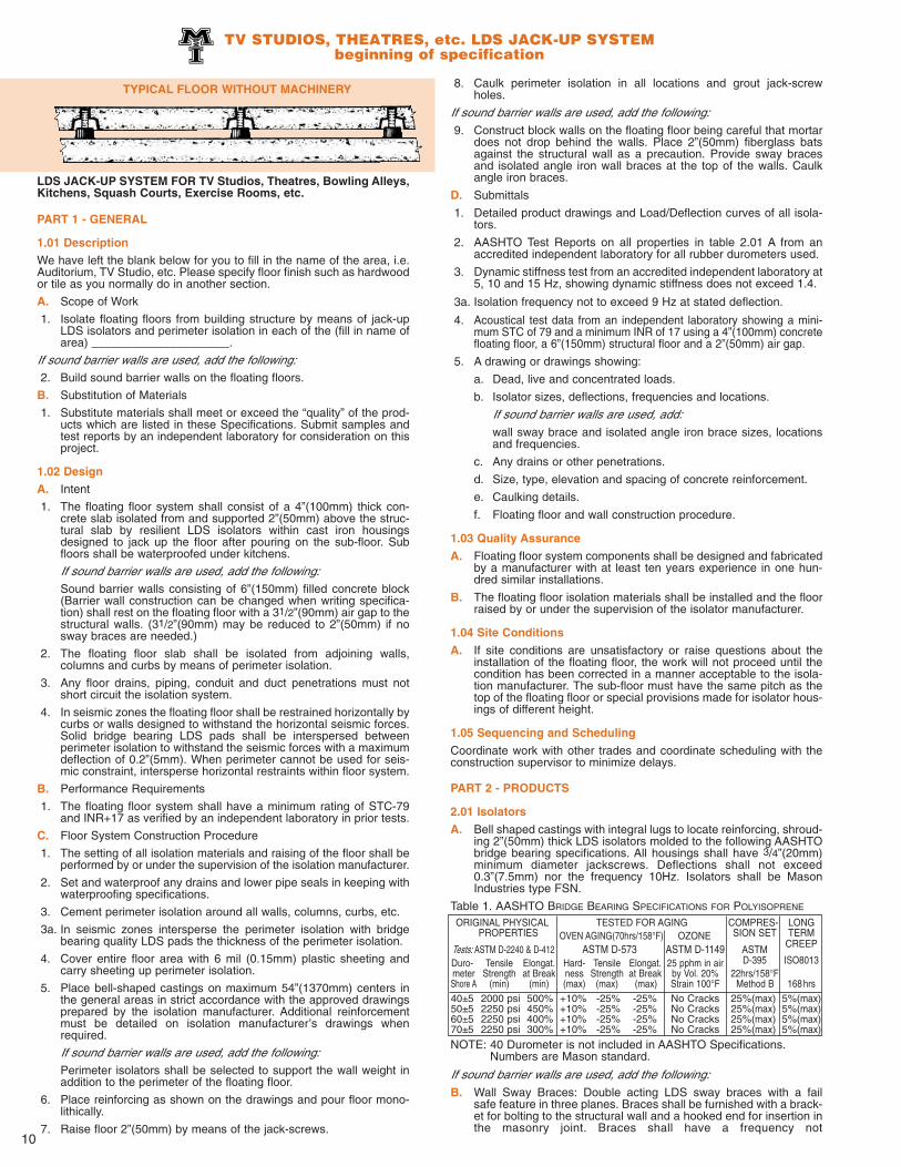
LDS JACK-UP SYSTEM FOR TV Studios, Theatres, Bowling Alleys,Kitchens, Squash Courts, Exercise Rooms, etc.
PART 1 - GENERAL
1.01 DescriptionWe have left the blank below for you to fill in the name of the area, i.e.Auditorium, TV Studio, etc. Please specify floor finish such as hardwoodor tile as you normally do in another section.
A. Scope of Work
1. Isolate floating floors from building structure by means of jack-upLDS isolators and perimeter isolation in each of the (fill in name ofarea) _____________________.
If sound barrier walls are used, add the following:
2. Build sound barrier walls on the floating floors.
B. Substitution of Materials
1. Substitute materials shall meet or exceed the “quality” of the prod-ucts which are listed in these Specifications. Submit samples andtest reports by an independent laboratory for consideration on thisproject.
1.02 DesignA. Intent
1. The floating floor system shall consist of a 4”(100mm) thick con-crete slab isolated from and supported 2”(50mm) above the struc-tural slab by resilient LDS isolators within cast iron housingsdesigned to jack up the floor after pouring on the sub-floor. Subfloors shall be waterproofed under kitchens.
If sound barrier walls are used, add the following:
Sound barrier walls consisting of 6”(150mm) filled concrete block(Barrier wall construction can be changed when writing specifica-tion) shall rest on the floating floor with a 31/2”(90mm) air gap to thestructural walls. (31/2”(90mm) may be reduced to 2”(50mm) if nosway braces are needed.)
2. The floating floor slab shall be isolated from adjoining walls,columns and curbs by means of perimeter isolation.
3. Any floor drains, piping, conduit and duct penetrations must notshort circuit the isolation system.
4. In seismic zones the floating floor shall be restrained horizontally bycurbs or walls designed to withstand the horizontal seismic forces.Solid bridge bearing LDS pads shall be interspersed betweenperimeter isolation to withstand the seismic forces with a maximumdeflection of 0.2”(5mm). When perimeter cannot be used for seis-mic constraint, intersperse horizontal restraints within floor system.
B. Performance Requirements
1. The floating floor system shall have a minimum rating of STC-79and INR+17 as verified by an independent laboratory in prior tests.
C. Floor System Construction Procedure
1. The setting of all isolation materials and raising of the floor shall beperformed by or under the supervision of the isolation manufacturer.
2. Set and waterproof any drains and lower pipe seals in keeping withwaterproofing specifications.
3. Cement perimeter isolation around all walls, columns, curbs, etc.
3a. In seismic zones intersperse the perimeter isolation with bridgebearing quality LDS pads the thickness of the perimeter isolation.
4. Cover entire floor area with 6 mil (0.15mm) plastic sheeting andcarry sheeting up perimeter isolation.
5. Place bell-shaped castings on maximum 54”(1370mm) centers inthe general areas in strict accordance with the approved drawingsprepared by the isolation manufacturer. Additional reinforcementmust be detailed on isolation manufacturer’s drawings whenrequired.
If sound barrier walls are used, add the following:
Perimeter isolators shall be selected to support the wall weight inaddition to the perimeter of the floating floor.
6. Place reinforcing as shown on the drawings and pour floor mono-lithically.
7. Raise floor 2”(50mm) by means of the jack-screws.
8. Caulk perimeter isolation in all locations and grout jack-screwholes.
If sound barrier walls are used, add the following:
9. Construct block walls on the floating floor being careful that mortardoes not drop behind the walls. Place 2”(50mm) fiberglass batsagainst the structural wall as a precaution. Provide sway bracesand isolated angle iron wall braces at the top of the walls. Caulkangle iron braces.
D. Submittals
1. Detailed product drawings and Load/Deflection curves of all isola-tors.
2. AASHTO Test Reports on all properties in table 2.01 A from anaccredited independent laboratory for all rubber durometers used.
3. Dynamic stiffness test from an accredited independent laboratory at5, 10 and 15 Hz, showing dynamic stiffness does not exceed 1.4.
3a. Isolation frequency not to exceed 9 Hz at stated deflection.
4. Acoustical test data from an independent laboratory showing a mini-mum STC of 79 and a minimum INR of 17 using a 4”(100mm) concretefloating floor, a 6”(150mm) structural floor and a 2”(50mm) air gap.
5. A drawing or drawings showing:
a. Dead, live and concentrated loads.
b. Isolator sizes, deflections, frequencies and locations.
If sound barrier walls are used, add:
wall sway brace and isolated angle iron brace sizes, locationsand frequencies.
c. Any drains or other penetrations.
d. Size, type, elevation and spacing of concrete reinforcement.
e. Caulking details.
f. Floating floor and wall construction procedure.
1.03 Quality Assurance
A. Floating floor system components shall be designed and fabricatedby a manufacturer with at least ten years experience in one hun-dred similar installations.
B. The floating floor isolation materials shall be installed and the floorraised by or under the supervision of the isolator manufacturer.
1.04 Site Conditions
A. If site conditions are unsatisfactory or raise questions about theinstallation of the floating floor, the work will not proceed until thecondition has been corrected in a manner acceptable to the isola-tion manufacturer. The sub-floor must have the same pitch as thetop of the floating floor or special provisions made for isolator hous-ings of different height.
1.05 Sequencing and Scheduling
Coordinate work with other trades and coordinate scheduling with theconstruction supervisor to minimize delays.
PART 2 - PRODUCTS
2.01 Isolators
A. Bell shaped castings with integral lugs to locate reinforcing, shroud-ing 2”(50mm) thick LDS isolators molded to the following AASHTObridge bearing specifications. All housings shall have 3/4”(20mm)minimum diameter jackscrews. Deflections shall not exceed0.3”(7.5mm) nor the frequency 10Hz. Isolators shall be MasonIndustries type FSN.
Table 1. AASHTO BRIDGE BEARING SPECIFICATIONS FOR POLYISOPRENE
NOTE: 40 Durometer is not included in AASHTO Specifications.Numbers are Mason standard.
If sound barrier walls are used, add the following:
B. Wall Sway Braces: Double acting LDS sway braces with a failsafe feature in three planes. Braces shall be furnished with a brack-et for bolting to the structural wall and a hooked end for insertion inthe masonry joint. Braces shall have a frequency not
TV STUDIOS, THEATRES, etc. LDS JACK-UP SYSTEMbeginning of specification
Business Card LogoTYPICAL FLOOR WITHOUT MACHINERY
ORIGINAL PHYSICAL TESTED FOR AGING COMPRES- LONGPROPERTIES OVEN AGING(70hrs/158°F) OZONE SION SET TERM
Duro- Tensile Elongat. Hard- Tensile Elongat. 25 pphm in air D-395 ISO8013meter Strength at Break ness Strength at Break by Vol. 20% 22hrs/158°FShore A (min) (min) (max) (max) (max) Strain 100°F Method B 168hrs40±5 2000 psi 500% +10% -25% -25% No Cracks 25%(max) 5%(max) 50±5 2250 psi 450% +10% -25% -25% No Cracks 25%(max) 5%(max) 60±5 2250 psi 400% +10% -25% -25% No Cracks 25%(max) 5%(max)70±5 2250 psi 300% +10% -25% -25% No Cracks 25%(max) 5%(max)
11
in excess of 10Hz based on the weight of the wall area per brace and avertical stiffness not in excess of 50% of the horizontal. Sway bracesshall be Mason Industries Type DNSB.
C. Angle Brackets: 11/2”(40mm) x 2”(50mm) angle iron sections withprovision for bolting to the structure and a minimum thickness of3/8”(9mm) sponge cemented to the vertical leg. Angle Brackets shallbe Mason Industries AB-716.
2.02 Bond Breaker Material
A. Provide one (1) layer of 6 mil (0.15mm) polyethylene sheeting.
2.03 Perimeter Isolation
A. Minimum 3/4”(20mm) thick PVC foam, density 7 lbs/ft3 average. PVCfoam shall be Mason Industries P7.
B. In seismic zone perimeter isolation shall be interspersed with3/4”(20mm) thick, 60 durometer LDS bridge bearing pads the heightof the perimeter material. Bridge bearing pad shall be made to thesame AASHTO specifications, as shown for the FSN mountings andsized for a maximum deflection of 0.2”(5mm) at maximum earth-quake forces. Interspersed pads shall be Mason Industries TypeLDS-BBP.
2.04 Perimeter Caulking Compound
A. Non-hardening, drying or bleeding. Troweling or pouring grade.Caulking compound shall be Mason Industries Type CC-75.
2.05 Floating Floor Drains
A. Cast iron design. The upper funnel section cast into the floating floor.Lower bucket, built into the structure, shall retain water surroundingthe upper section as a between floors sound seal. Weep holes arerequired to drain the structural floor. Floor drains shall have waterproofing membrane clamps. Floor drains shall be Mason IndustriesType CFD-18591.
PART 3 - EXECUTION
3.01 Installation
Install the floating floor systems according to the installation and adjust-ment procedures and drawings submitted by the isolator manufacturerand approved by the architect.
––––––––––––––––––– End of Specification ––––––––––––––––––
LDS JACK-UP SYSTEM FOR ROOFS.
PART 1 - GENERAL
1.01 Description
A. Scope of Work
1. Isolate floating roofs from the building structure by means of jack-upLDS isolators and perimeter isolation in each of the roof areasshown on the drawings.
If sound barrier walls are used, add the following:
2. Build sound barrier walls on the floating floors.
B. Substitution of Materials
1. Substitute materials shall meet or exceed the “quality” of the productswhich are listed in these Specifications. Submit samples and testreports by an independent laboratory for consideration on this project.
1.02 Design
A. Intent
1. The floating roof system shall consist of a 4”(100mm) waterproofedconcrete slab isolated and supported 2”(50mm) above the water-proofed structural slab by resilient LDS isolators within cast ironhousings designed to jack up the roof after pouring on the sub-roof.
If sound barrier walls are used, add the following:
Sound barrier walls consisting of 6”(150mm) filled concrete block(Barrier wall construction can be changed when writing specifica-tion) shall rest on the floating floor.
2. The floating roof slab shall be isolated from adjoining walls, columns,and curbs by means of perimeter isolation.
3. Any equipment mounted directly on the floating roof shall beinstalled so as not to damage the roof’s waterproofing.
4. Flashing and waterproofing shall be completed after the roof israised. Perimeter flashing shall allow for downward movement of0.5”(12mm).
5. In seismic zones the floating floor shall be restrained horizontally bycurbs or walls designed to withstand the horizontal seismic forces.Solid bridge bearing LDS pads shall be interspersed betweenperimeter isolation to withstand the seismic forces with a maximumdeflection of 0.2”(5mm). When perimeter cannot be used for seis-mic constraint, intersperse horizontal restraints within floor system.
6. In seismic zones 2, 3 and 4 or equivalent Av, the roof shall be protect-ed by embedded double acting resilient floor snubbers set in opposi-tion to the overturning moments at the equipment snubbers in all loca-tions where the center of gravity of major equipment is high.
B. Performance Requirements
1. The floating roof system shall have a minimum rating of STC-79and INR+17 as verified by an independent laboratory in prior tests.
C. Roof System Construction Procedure
1. The setting of all isolation materials and raising of the roof shall beperformed by or under the supervision of the isolation manufactur-er.
2. Set and waterproof any drains and lower pipe seals in keeping withwaterproofing specifications.
3. Cement perimeter isolation around all walls, columns, curbs, etc.
3a. In seismic zones intersperse the perimeter isolation with bridgebearing quality LDS pads the thickness of the perimeter isolation.
4. Cover entire floor area with 6 mil (0.15mm) plastic sheeting andcarry sheeting up perimeter isolation.
5. Place bell-shaped castings on maximum 54”(1370mm) centers inthe general areas in strict accordance with the approved drawingsprepared by the isolation manufacturer. Spacing can be increasedto straddle machinery locations. Additional reinforcement must bedetailed on isolation manufacturer’s drawings when required.
If sound barrier walls are used, add the following:Perimeter isolators shall be selected to support the wall weight inaddition to the perimeter of the floating roof.
5a. In seismic zones attach double acting resilient seismic snubbers tothe structural slab on either side of high center of gravity equipmentto withstand the overturning moment generated by the machinerysnubbers and prevent failure of the floating roof.
6. Place reinforcing as shown on the drawings and pour roof mono-lithically.
7. Raise roof 2”(50mm) by means of the jack-screws. (If constructionssequence dictates raising the roof before placing machinery, heavyplanking must be used to protect the roof if machinery is rolled intoposition).
8. Caulk perimeter isolation in all locations and grout jack-screw holes.
If sound barrier walls are used, add the following:9. Construct block walls on the floating floor being careful that mortar
does not drop behind the walls. Place 2”(50mm) fiberglass batsagainst the structural wall as a precaution. Provide sway bracesand isolated angle iron wall braces at the top of the walls. Caulkangle iron braces.
10. In seismic zones adjust the double acting snubbers after machineryis in place to provide a maximum up and down clearance of0.125”(3mm).
11. Install waterproofing and flashing.
D. Submittals
1. Detailed product drawings and Load/Deflection curves of all isola-tors and in seismic zones double acting floor snubbers.
2. AASHTO Test Reports on all properties in table 2.01 A from anaccredited independent laboratory for all rubber durometers used.
3. Dynamic stiffness test from an accredited independent laboratory at5, 10 and 15 Hz, showing dynamic stiffness does not exceed 1.4.
3a. Isolation frequency not to exceed 9 Hz at stated deflection.
4. Acoustical test data from an independent laboratory showing a min-imum STC of 79 and a minimum INR of 17 using a 4”(100mm) con-crete floating floor, a 6”(150mm) structural floor and a 2”(50mm) airgap.
5. A drawing or drawings showing:
a. Dead, live and concentrated loads.
b. Isolator sizes, deflections, frequencies and locations and inseismic zones, locations of seismic snubbers.
c. Any drains or other penetrations.
d. Size, type, elevation and spacing of concrete reinforcement.
e. Caulking details.
f. Roof system construction procedure.
TV STUDIOS, THEATRES, etc. LDS JACK-UP SYSTEM specification concludedLDS JACK-UP SYSTEM for ROOFS beginning of specification
Business Card Logo
12
The damping provided by the air under spring supported floors is nor-mally adequate to limit motion. Occasionally, particularly in smallaerobic rooms, rhythmic exercises amplify floor motion so additionaldamping is desirable. The RIS (rubber-in-shear) element solves thisproblem. Elements are interchangeable with FS springs and can beinstalled in existing housings if needed or included in the design stagein supplementary locations. Damping rate is controlled by hardness,material and number of dampers.
SPRING JACK-UP SYSTEM FOR TV STUDIOS, THEATRES, BOWL-ING ALLEYS, KITCHENS, SQUASH COURTS, EXERCISE ROOMS,ETC.
PART 1 - GENERAL
1.01 Description
A. Scope of Work
1. Isolate floating floors from the building structure by means of jack-up spring isolators and perimeter isolation in each of the______________ rooms as shown on the drawings. (Architect to fillin name of room.)
If sound barrier walls are used, add the following:
2. Build sound barrier walls on the floating floors.
B. Substitution of Materials
1. Substitute materials shall meet or exceed the “quality” of the prod-ucts which are listed in these Specifications. Submit samples forconsideration on this project.
1.02 Design
A. Intent
1. The floating floor system shall consist of a 4”(100mm) thick con-crete slab isolated from and supported 2”(50mm) above the struc-tural slab by resilient spring isolators within cast iron housingsdesigned to jack up the floor after pouring on the sub-floor.
If sound barrier walls are used, add the following:
Sound barrier walls consisting of 6”(150mm) filled concrete block(Barrier wall construction may be changed by the architect whenwriting specification) shall rest on the floating floor with a31/2”(90mm) air gap to the structural walls. (3”(90mm) may bereduced to 2”(50mm) if no sway braces are needed.)
2. The floating floor slab shall be isolated from adjoining walls andcurbs by means of perimeter isolation.
1.03 Quality Assurance
A. Floating roof system components shall be designed and fabricatedby a manufacturer with at least ten years experience in one hundredsimilar floor or roof installations.
B. The floating roof isolation materials shall be installed and the roofraised by or under the supervision of the isolator manufacturer.
1.04 Site Conditions
A. If site conditions are unsatisfactory or raise questions about theinstallation of the floating roof, the work will not proceed until thecondition has been corrected in a manner acceptable to the isola-tion manufacturer. The sub-roof must have the same pitch as thetop of the floating roof or special provisions made for isolator hous-ings of different height.
1.05 Sequencing and Scheduling
Coordinate work with other trades and coordinate scheduling with theconstruction supervisor to minimize delays.
PART 2 - PRODUCTS
2.01 Isolators
A. Bell shaped castings with integral lugs to locate reinforcing, shroud-ing 2”(50mm) thick LDS isolators molded to the following AASHTObridge bearing specifications. All housings shall have 3/4”(20mm)minimum diameter jackscrews. Deflections shall not exceed0.3”(7.5mm) nor the frequency 10Hz. Isolator shall be MasonIndustries type FSN.
Table 1. AASHTO BRIDGE BEARING SPECIFICATIONS FOR POLYISOPRENE
NOTE: 40 Durometer is not included in AASHTO Specifications.Numbers are Mason standard.
B. In seismic zones double acting resilient cast in floating floor snub-bers shall consist of a ductile iron housing locked into the floatingfloor. The housing shall have a removable cover plate to provideaccess to the adjustment of clearances in both the up and downdirections of the resilient stops. Resilient stops shall be attached toa restraining bolt attached to the structural floor with an approvedanchor. Double acting snubbers shall be Mason Industries TypeSFFS.
2.02 Bond Breaker Material
A. Provide one (1) layer of 6 mil (0.15mm) polyethylene sheeting.
2.03 Perimeter Isolation
A. Minimum 3/4”(20mm) thick PVC foam, density 7 lbs/ft3 average.PVC foam shall be Mason Industries P7.
B. In seismic zone perimeter isolation shall be interspersed with3/4”(20mm) thick, 60 durometer LDS bridge bearing pads the heightof the perimeter material. Bridge bearing pad shall be made to thesame AASHTO specifications, as shown for the FSN mountings andsized for a maximum deflection of 0.2”(5mm) at maximum earth-quake forces. Interspersed pads shall be Mason Industries TypeLDS-BBP.
2.04 Perimeter Caulking Compound
A. Non-hardening, drying or bleeding. Troweling or pouring grade.Caulking compound shall be Mason Industries Type CC-75.
2.05 Floating Roof Drains
A. Use standard roof drains cast into the floating roof. The structuralfloor shall have openings large enough to access pipe connectionsto the drains. Drain piping shall be suspended from combinationspring and LDS hangers with a minimum of 1”(25mm) static deflec-tion for 40 feet(12 meters) from the attachment point as shown onthe drawings.
B. Roof drains shall be (Architects Preference)
PART 3 - EXECUTION
3.01 Installation
Install the floating roof systems according to the installation and adjust-ment procedures and drawings submitted by the isolator manufacturerand approved by the architect.
LDS JACK-UP SYSTEM for ROOFS specification concludedSPRING JACK-UP SYSTEM beginning of specification
Business Card Logo
TYPICAL SPRING CROSS SECTION
Type FSSPRING
JACK-UPMOUNT
Type RISRUBBER-IN-SHEAR
FLOOR DAMPER
RIS ReplaceableElement Interchangeablewith Spring Assembly
Duro- Tensile Elongat. Hard- Tensile Elongat. 25 pphm in air D-395 ISO8013meter Strength at Break ness Strength at Break by Vol. 20% 22hrs/158°FShore A (min) (min) (max) (max) (max) Strain 100°F Method B 168hrs40±5 2000 psi 500% +10% -25% -25% No Cracks 25%(max) 5%(max) 50±5 2250 psi 450% +10% -25% -25% No Cracks 25%(max) 5%(max) 60±5 2250 psi 400% +10% -25% -25% No Cracks 25%(max) 5%(max)70±5 2250 psi 300% +10% -25% -25% No Cracks 25%(max) 5%(max)
13
1.05 Sequencing and Scheduling
Coordinate work with other trades and coordinate scheduling with theconstruction supervisor to minimize delays.
PART 2 - PRODUCTS
2.01 Isolators
A. Casting or weldments consisting of an internally threaded outer hous-ing complete with lugs to support the reinforcing system. The innerinverted cup shaped housing shall be externally threaded. Thesprings are compressed and the floor lifted by turns of the internalhousing. Springs shall be seated in neoprene cups and housingsshall have removable cover plates. Spring diameters shall be no lessthan 0.8 of the compressed height of the spring at rated load. Springsshall have a minimum additional travel to solid equal to 50% of therated deflection. Spring deflections shall be a minimum of0.75”(20mm). (Note to architect: Deflections may be changed asrequired.) Isolators shall be Mason Industries Type FS.
If sound barrier walls are used, add the following:
B. Wall Sway Braces: Double acting LDS sway braces with a fail safefeature in three planes. Braces shall be furnished with a bracket forbolting to the structural wall and a hooked end for insertion in themasonry joint. Braces shall have a frequency not in excess of 10Hzbased on the weight of the wall area per brace and a vertical stiff-ness not in excess of 50% of the horizontal. Sway Braces shall beMason Industries Type DNSB.
C. Angle Brackets: 11/2”(40mm) x 2”(50mm) angle iron sections withprovision for bolting to the structure and a minimum thickness of3/8”(9mm) sponge cemented to the vertical leg. Angle Bracketsshall be Mason Industries Type AB-716.
2.02 Bond Breaker Material
A. Provide one (1) layer of 6 mil (0.15mm) polyethylene sheeting.
2.03 Perimeter Isolation
A. Minimum 3/4”(20mm) thick PVC foam, density 7 lbs/ft3 average.PVC foam shall be Mason Industries P7.
B. In seismic zone perimeter isolation shall be interspersed with3/4”(20mm) thick, 60 durometer LDS bridge bearing pads the heightof the perimeter material. Bridge bearing pad shall be made toAASHTO specifications, as shown and sized for a maximum deflec-tion of 0.2”(5mm) at maximum earthquake forces. Interspersedpads shall be Mason Industries Type LDS-BBP.
Table 1. AASHTO BRIDGE BEARING SPECIFICATIONS FOR POLYISOPRENE
NOTE: 40 Durometer is not included in AASHTO Specifications.Numbers are Mason standard.
2.04 Perimeter Caulking Compound
A. Non-hardening, drying or bleeding. Troweling or pouring grade.Caulking compound shall be Mason Industries Type CC-75.
2.05 Floating Floor Drains
A. Cast iron design. The upper funnel section cast into the floatingfloor. Lower bucket, built into the structure, shall retain water sur-rounding the upper section as a between floors sound seal. Weepholes are required to drain the structural floor. Floor drains shallhave water proofing membrane clamps. Floor drains shall beMason Industries Type CFD-18591.
PART 3 - EXECUTION
3.01 Installation
Install the floating floor systems according to the installation and adjust-ment procedures and drawings submitted by the isolator manufacturerand approved by the architect.
Note to Architect: When theatres have sharply sloped floors, FSN or FSmountings must be furnished with round cast iron or neoprene wedgesat each FSN or FS location so mountings are installed level. In extremecases a restraining curb is needed at the base of the slope or the end ofthe straight section adjoining the slope.
3. Any floor drains, piping, conduit and duct penetrations must notshort circuit the isolation system.
4. In seismic zones the floating floor shall be restrained horizontally bycurbs or walls designed to withstand the horizontal seismic forces.Solid bridge bearing LDS pads shall be interspersed betweenperimeter isolation to withstand the seismic forces with a maximumdeflection of 0.2”(5mm). When perimeter cannot be used for seis-mic constraint, intersperse horizontal restraints within floor system.
B. Performance Requirements
1. All spring isolators shall have the minimum specified deflection.
C. Floor System Construction Procedure
1. The setting of all isolation materials and raising of the floor shall beperformed by or under the supervision of the isolation manufactur-er.
2. Set and waterproof any drains and lower pipe seals in keeping withwaterproofing specifications.
3. Cement perimeter isolation around all walls, columns, curbs, etc.
3a. In seismic zones intersperse the perimeter isolation with bridgebearing quality LDS pads the thickness of the perimeter isolation.
4. Cover entire floor area with 6 mil (0.15mm) polyethylene sheetingand carry sheeting up perimeter isolation.
5. Place spring isolator castings on a maximum of 54”(1370mm) cen-ters in the general areas in strict accordance with the approveddrawings prepared by the isolation manufacturer. Additional rein-forcement such as in wall locations must be detailed on isolationmanufacturer’s drawings when required.
If sound barrier walls are used, add the following:
Perimeter isolators shall be selected to support the wall weight inaddition to the perimeter of the floating floor.
6. Place reinforcing as shown on the drawings and pour floor mono-lithically.
7. Raise floor 2”(50mm) by means of the isolator threaded sleevesand replace covers.
8. Caulk perimeter isolation in all locations.
If sound barrier walls are used, add the following:
9. Construct block walls on the floating floor being careful that mortardoes not drop behind the walls. Place 2”(50mm) fiberglass batsagainst the structural wall as a precaution. Readjust perimeter iso-lators as required to compensate for wall weight as the wall is built.Provide sway braces and isolated angle iron wall braces at the topof the walls. Caulk angle iron braces.
D. Submittals
1. Detailed product drawings including Load/Deflection curves of allisolators.
2. Drawing or drawings showing:
a. Dead, live and concentrated loads.
b. Isolator sizes, deflections and locations.
If sound barrier walls are used, add the following to b:
Wall sway brace and isolated angle iron brace locations.
c. Any drain and penetration locations.
d. Size, type, elevation and spacing of concrete reinforcement.
e. Caulking details.
f. Floating floor and wall construction procedure.
1.03 Quality Assurance
A. Floating floor system components shall be designed and fabricatedby a manufacturer with at least ten years experience in one hundredsimilar installations.
B. The floating floor isolation materials shall be installed and the floorraised by or under the supervision of the isolator manufacturer.
1.04 Site Conditions
A. If site conditions are unsatisfactory or raise questions about theinstallation of the floating floor, the work will not proceed until thecondition has been corrected in a manner acceptable to the isola-tion manufacturer. The sub-floor must have the same pitch as thetop of the floating floor or special provisions made for isolator hous-ings of different height.
SPRING JACK-UP SYSTEM specification concluded
Business Card Logo
ORIGINAL PHYSICAL TESTED FOR AGING COMPRES- LONGPROPERTIES OVEN AGING(70hrs/158°F) OZONE SION SET TERM
Duro- Tensile Elongat. Hard- Tensile Elongat. 25 pphm in air D-395 ISO8013meter Strength at Break ness Strength at Break by Vol. 20% 22hrs/158°FShore A (min) (min) (max) (max) (max) Strain 100°F Method B 168hrs40±5 2000 psi 500% +10% -25% -25% No Cracks 25%(max) 5%(max) 50±5 2250 psi 450% +10% -25% -25% No Cracks 25%(max) 5%(max) 60±5 2250 psi 400% +10% -25% -25% No Cracks 25%(max) 5%(max)70±5 2250 psi 300% +10% -25% -25% No Cracks 25%(max) 5%(max)
14
MECHANICAL EQUIPMENT ROOM LDS FORM-WORK SYSTEMbeginning of specification
LDS FORM-WORK SYSTEM FOR MECHANICAL EQUIPMENTROOMS WITH MACHINERY SUPPORTED BY THE FLOATINGFLOOR.
PART 1 - GENERAL
1.01 Description
A. Scope of Work
1. Isolate floating floors from building structure by means of LDSisolators under plywood panels and perimeter isolation in mechani-cal equipment rooms as shown on the drawings.
If sound barrier walls are used, add the following:
2. Build sound barrier walls on the floating floors.
B. Substitution of Materials
1. Substitute materials shall meet or exceed the “quality” of the prod-ucts which are listed in these Specifications. Submit samples andtest reports by an independent laboratory for consideration on thisproject.
1.02 Design
A. Intent
1. The floating floor shall consist of a 4”(100mm) thick concrete slabisolated from and supported 21/2”(62mm) above the waterproofedstructural slab by resilient LDS isolators covered by 1/2” (12mm)plywood panels that form the pouring surface.
If sound barrier walls are used, add the following:
Sound barrier walls consisting of 6”(150mm) filled concrete block(Barrier wall construction may be changed by architect when writingspecification) shall rest on the floating floor with a 31/2”(90mm) airgap to the structural walls. (31/2”(90mm) may be reduced to2”(50mm) if no sway braces are needed.)
2. The floating floor slab shall be isolated from adjoining walls andcurbs by means of perimeter isolation.
3. Any floor drains, piping, conduit and duct penetrations must notshort circuit the isolation system.
4. Any equipment within these rooms shall be mounted on house-keeping pads or directly on the floating floor as shown on the draw-ings.
5. In seismic zones the floating floor shall be restrained horizontally bycurbs or walls designed to withstand the horizontal seismic forces.Solid bridge bearing LDS pads shall be interspersed betweenperimeter isolation to withstand the seismic forces with a maximumdeflection of 0.2”(5mm). When perimeter cannot be used for seis-mic constraint, intersperse horizontal restraints within floor system.
6. In seismic zones 2, 3 and 4 or equivalent Av, the floor shall be pro-tected by embedded double acting resilient floor snubbers set inopposition to the overturning moments at the equipment snubbersin all locations where the center of gravity of major equipment ishigh.
B. Performance Requirements
1. The floating floor system shall have a minimum rating of STC-79and INR+17 as verified by an independent laboratory in prior tests.
C. Floor System Construction Procedure
1. The setting of all isolation materials shall be performed by or underthe supervision of the isolation manufacturer.
2. Set and waterproof any drains and lower pipe seals in keeping withwaterproofing specifications.
3. Cement perimeter isolation around all walls, columns, curbs, etc.
3a. In seismic zones intersperse the perimeter isolation with bridgebearing quality LDS pads the thickness of the perimeter isolation.
4. Place individual LDS isolators on the sub-floor at a maximum spac-ing of 24”(600mm) in strict accordance with the approved drawingsprepared by the isolation manufacturer. Additional reinforcementmust be detailed on isolation manufacturer’s drawings whenrequired.
If sound barrier isolation walls are used, add the following:
Perimeter isolators shall be selected to support the wall weight inaddition to the perimeter of the floating floor.
5. In seismic zones provide anchorage for the double acting resilientvertical snubbers to the structural slab. Snubber anchor bolts mustbe in close proximity to the mechanical snubbers restraining anyhigh center of gravity equipment to withstand the overturningmoments generated by the machinery snubbers and prevent failureof the floating floor.
6. Cover isolators with 1/2”(12mm) AC plywood. Isolators shall belocated under joints and joints staggered. Connect plywood at abut-ting edges and corners with 16 gauge steel junction plates.
7. Cover the plywood with 6 mil (0.15mm) plastic sheeting and carry itup the walls past the perimeter isolation.
8. Place seismic snubber housings on the anchor bolts that protrudefrom the structural floor and through the plywood.
9. Place reinforcing as shown on the drawings and pour floor mono-lithically.
POLYETHYLENESHEETING
REINFORCING
HOUSEKEEPING
PAD
EAFM LDSMOUNTS
ISOLATION
PLY-WOOD
EAFMFLOATING
FLOOR
AIRGAP
FLOORDRAIN
Business Card Logo
CAULKED PERIMETER
ISOLATION BOARD
Type CFDA4 x 4FLOOR DRAIN
Type EAFMLDS FLOOR MOUNT
10. After the concrete has hardened, caulk all perimeter isolation.
If sound barrier walls are used, add the following:
Construct block walls on the floating floor being careful that mortardoes not drop behind the walls. Place 2”(50mm) fiberglass batsagainst the structural wall as a precaution. Provide sway braces andisolated angle iron wall braces at the top of the walls. Caulk angleiron braces.
11. In seismic zones adjust the double acting snubbers after machineryis in place to provide a maximum up and down clearance of0.125”(3mm).
D. Submittals
1. Detailed product drawings and Load/Deflection curves of all isola-tors. In seismic zones details of double acting floor snubbers.
2. AASHTO Test Reports on all properties in table 2.01 A from anaccredited independent laboratory for all rubber durometers used.
3. Dynamic stiffness test from an accredited independent laboratory at5, 10 and 15 Hz, showing dynamic stiffness does not exceed 1.4.
3a. Isolation frequency not to exceed 9 Hz at stated deflection.
4. Acoustical test data from an independent laboratory showing a min-imum STC-79 and a minimum INR+17 using a 4”(100mm) concretefloating floor, a 6”(150mm) structural floor and 2”(50mm) air gap.
5. A drawing or drawings showing:
a. Dead, live and concentrated loads.
b. Isolators sizes, deflections, frequencies and locations. In seismiczones add: “Locations and details of seismic snubbers”.
If sound barrier walls are used, add the following:
Wall sway brace and isolator, angle iron brace sizes, locations andfrequencies.
c. Any drain and penetration locations.
d. Size type elevation and spacing of concrete reinforcement.
e. Caulking details.
f. Floating floor and wall construction procedure.
1.03 Quality Assurance
A. Floating floor system components shall be designed and fabricatedby a manufacturer with at least ten years experience in one hundredsimilar installations.
B. The floating floor isolation materials and panel board forms shall beinstalled under the supervision of the isolator manufacturer.
1.04 Site Conditions
A. If site conditions are unsatisfactory or raise questions about theinstallation of the floating floor, the work will not proceed until thecondition has been corrected in a manner acceptable to the isolationmanufacturer.
1.05 Sequencing and Scheduling
Coordinate work with other trades and coordinate scheduling with theconstruction supervisor to minimize delays.
PART 2 - PRODUCTS
2.01 Isolators
A. Cylindrical LDS mountings with a diameter no less than 0.9 of the2”(50mm) height. Isolators are molded to the following LDS AASH-TO bridge bearing specification. Maximum durometer 60.Deflections shall not exceed 0.3”(7.5mm) nor the frequency 10Hz.Isolators shall be Mason Industries Type EAFM.
Table 1. AASHTO BRIDGE BEARING SPECIFICATIONS FOR POLYISOPRENE
NOTE: 40 Durometer is not included in AASHTO Specifications.Numbers are Mason standard.
B. In seismic zones double acting resilient cast in floating floor snub-bers shall consist of a ductile iron housing locked into the floatingfloor. The housing shall have a removable cover plate to provideaccess to the adjustment of resilient stop clearances in both the upand down directions. Resilient stops shall be attached to a
restraining bolt attached to the structural floor with an approvedanchor. Double acting snubbers shall be Mason Industries TypeSFFS.
If sound barrier walls are used, add the following:
C. Wall Sway Braces: Double acting LDS sway braces with a fail safefeature in three planes. Braces shall be furnished with a bracket forbolting to the structural wall and a hooked end for insertion in themasonry joint. Braces shall have a frequency not in excess of 10Hzbased on the weight of the wall area per brace and a vertical stiff-ness not in excess of 50% of the horizontal. Sway Braces shall beMason Industries Type DNSB.
D. Angle Brackets: 11/2”(40mm) x 2”(50mm) angle iron sections withprovision for bolting to the structure and a minimum thickness of3/8”(9mm) sponge cemented to the vertical leg. Angle Bracketsshall be Mason Industries Type AB-716.
2.02 Plywood Covering Material
A. Provide one (1) layer of 6 mil (0.15mm) polyethylene sheeting.
2.03 Perimeter Isolation
A. Minimum 3/4”(20mm) thick PVC foam, density 7 lbs/ft3 average.PVC foam shall be Mason Industries P7.
B. In seismic zone perimeter isolation shall be interspersed with3/4”(20mm) thick, 60 durometer LDS bridge bearing pads the heightof the perimeter material. Bridge bearing pad shall be made to thesame AASHTO specifications, as shown for the EAFM mountingsand sized for a maximum deflection of 0.2”(5mm) at maximumearthquake forces. Interspersed pads shall be Mason IndustriesType LDS-BBP.
2.04 Perimeter Caulking Compound
A. Non-hardening, drying or bleeding. Troweling or pouring grade.Caulking compound shall be Mason Industries Type CC-75.
2.05 Floating Floor Drains
A. Cast iron design. The upper funnel section cast into the floatingfloor. Lower bucket, built into the structure, shall retain water sur-rounding the upper section as a between floors sound seal. Weepholes are required to drain the structural floor. Floor drains shallhave water proofing membrane clamps. Floor drains shall beMason Industries Type CFD-18591.
2.06 Plywood
A. Type AC exterior grade 1/2”(12mm) thick.
PART 3 - EXECUTION
3.01 Installation
Install the floating floor systems according to the installation and adjust-ment procedures and drawings submitted by the isolator manufacturerand approved by the architect.
Duro- Tensile Elongat. Hard- Tensile Elongat. 25 pphm in air D-395 ISO8013meter Strength at Break ness Strength at Break by Vol. 20% 22hrs/158°FShore A (min) (min) (max) (max) (max) Strain 100°F Method B 168hrs40±5 2000 psi 500% +10% -25% -25% No Cracks 25%(max) 5%(max) 50±5 2250 psi 450% +10% -25% -25% No Cracks 25%(max) 5%(max) 60±5 2250 psi 400% +10% -25% -25% No Cracks 25%(max) 5%(max)70±5 2250 psi 300% +10% -25% -25% No Cracks 25%(max) 5%(max)
16
5. Cover isolators with 1/2”(12mm) AC plywood. Isolators shall belocated under joints and joints staggered. Connect plywood at abut-ting edges with plywood junction plates.
6. Cover the plywood with polyethylene sheeting and carry it up thewalls past the perimeter isolation.
7. Place reinforcing as shown on the drawings and pour floor mono-lithically.
8. After the concrete has hardened, caulk all perimeter isolation.
If sound barrier walls are used, add 9.
9. Construct block walls on the floating floor being careful that mortardoes not drop behind the walls. Place 2”(50mm) fiberglass batsagainst the structural wall as a precaution. Provide sway bracesand isolated angle iron wall braces at the top of the walls. Caulkangle iron braces.
D. Submittals
1. Detailed product drawings and load /deflection curves of all isola-tors.
2. AASHTO Test Reports on all properties in table 2.01 A from anaccredited independent laboratory for all rubber durometers used.
3. Dynamic stiffness test from an accredited independent laboratory at5, 10 and 15 Hz, showing dynamic stiffness does not exceed 1.4.
3a. Isolation frequency not to exceed 9 Hz at stated deflection.
4. Acoustical test data from an independent laboratory showing a min-imum STC-79 and a minimum INR+17 using a 4”(100mm) concretefloating floor, a 6”(150mm) structural floor and 2”(50mm) air gap.
5. A drawing or drawings showing:
a. Dead, live and concentrated loads.
b. Isolators sizes, deflections, frequencies and locations.
If sound barrier walls are used, add the following:
Wall sway brace and isolator, angle iron brace sizes, locationsand frequencies.
c. Any drain and penetration locations.
d. Size type elevation and spacing of concrete reinforcement.
e. Caulking details.
f. Floating floor and wall construction procedure.
1.03 Quality Assurance
A. Floating floor system components shall be designed and fabricatedby a manufacturer with at least ten years experience in one hundredsimilar installations.
B. The floating floor isolation materials and panel board forms shall beinstalled under the supervision of the isolator manufacturer.
1.04 Site Conditions
A. If site conditions are unsatisfactory or raise questions about theinstallation of the floating floor, the work will not proceed until thecondition has been corrected in a manner acceptable to the isola-tion manufacturer.
1.05 Sequencing and Scheduling
Coordinate work with other trades and coordinate scheduling with theconstruction supervisor to minimize delays.
PART 2 - PRODUCTS
2.01 Isolators
A. Cylindrical LDS mountings with a diameter no less than 0.9 of the2”(50mm) height. Isolators are molded to the following LDS AASH-TO bridge bearing specification. Maximum durometer 60.Deflections shall not exceed 0.3”(7.5mm) nor the frequency 10Hz.Isolators shall be Mason Industries Type EAFM.
Table 1. AASHTO BRIDGE BEARING SPECIFICATIONS FOR POLYISOPRENE
NOTE: 40 Durometer is not included in AASHTO Specifications.Numbers are Mason standard.
LDS FORM-WORK SYSTEM FOR TV STUDIOS, THEATRES, BOWL-ING ALLEYS, KITCHEN, SQUASH COURTS, EXERCISE ROOMS,ETC.
PART 1 - GENERAL
1.01 Description
A. Scope of Work
1. Isolate floating floors from building structure by means of LDSisolators under plywood panels and perimeter isolation in mechani-cal equipment rooms as shown on the drawings.
If sound barrier walls are used, add the following:
2. Build sound barrier walls on the floating floors.
B. Substitution of Materials
1. Substitute materials shall meet or exceed the “quality” of the prod-ucts which are listed in these Specifications. Submit samples andtest reports by an independent laboratory for consideration on thisproject.
1.02 Design
A. Intent
1. The floating floor shall consist of a 4”(100mm) thick concrete slabisolated from and supported 21/2”(62mm) above the waterproofedstructural slab by resilient LDS isolators covered by plywoodpanels that form the pouring surface.
If sound barrier walls are used, add the following:
Sound barrier walls consisting of 6” (150mm) filled concrete block(Barrier wall construction may be changed by architect when writingspecification) shall rest on the floating floor with a 31/2”(90mm) airgap to the structural walls. (31/2”(90mm) may be reduced to2”(50mm) if no sway braces are needed.)
2. The floating floor slab shall be isolated from adjoining walls andcurbs by means of perimeter isolation.
3. Any floor drains, piping, conduit and duct penetrations must notshort circuit the isolation system.
4. Any equipment within these rooms shall be mounted on house-keeping pads or directly on the floating floor as shown on the draw-ings.
5. In seismic zones the floating floor shall be restrained horizontally bycurbs or walls designed to withstand the horizontal seismic forces.Solid bridge bearing LDS pads shall be interspersed betweenperimeter isolation to withstand the seismic forces with a maximumdeflection of 0.2”(5mm). When perimeter cannot be used for seis-mic constraint, intersperse horizontal restraints within floor system.
B. Performance Requirements
1. The floating floor system shall have a minimum rating of STC-79and INR+17 as verified by an independent laboratory in prior tests.
C. Floor System Construction Procedure
1. The setting of all isolation materials shall be performed by or underthe supervision of the isolation manufacturer.
2. Set and waterproof any drains and lower pipe seals in keeping withwaterproofing specifications.
3. Cement perimeter isolation around all walls, columns, curbs, etc.
3a. In seismic zones intersperse the perimeter isolation with bridgebearing quality LDS pads the thickness of the perimeter isolation.
4. Place individual LDS isolators on the sub-floor at a maximum spac-ing of 24” (600mm) in strict accordance with the approved drawingsprepared by the isolation manufacturer. Additional reinforcementmust be detailed on isolation manufacturer’s drawings whenrequired.
If sound barrier isolation walls are used, add the following:
Perimeter isolators shall be selected to support the wall weight inaddition to the perimeter of the floating floor.
TV STUDIOS, THEATRES, etc. LDS FORM-WORK SYSTEMbeginning of specification
Business Card LogoTYPICAL SLOPED THEATRE FLOOR
ORIGINAL PHYSICAL TESTED FOR AGING COMPRES- LONGPROPERTIES OVEN AGING(70hrs/158°F) OZONE SION SET TERM
Duro- Tensile Elongat. Hard- Tensile Elongat. 25 pphm in air D-395 ISO8013meter Strength at Break ness Strength at Break by Vol. 20% 22hrs/158°FShore A (min) (min) (max) (max) (max) Strain 100°F Method B 168hrs40±5 2000 psi 500% +10% -25% -25% No Cracks 25%(max) 5%(max) 50±5 2250 psi 450% +10% -25% -25% No Cracks 25%(max) 5%(max) 60±5 2250 psi 400% +10% -25% -25% No Cracks 25%(max) 5%(max)70±5 2250 psi 300% +10% -25% -25% No Cracks 25%(max) 5%(max)
17
2. The floating roof slab shall be isolated from adjoining walls andcurbs by means of perimeter isolation.
3. Any floor drains, piping, conduit and duct penetrations must notshort circuit the isolation system.
4. Any equipment on the roof shall be mounted on housekeeping padsor directly on the floating roofs as shown on the drawings, andinstalled so as not to damage the roof’s waterproofing.
5. In seismic zones the floating floor shall be restrained horizontally bycurbs or walls designed to withstand the horizontal seismic forces.Solid bridge bearing LDS pads shall be interspersed betweenperimeter isolation to withstand the seismic forces with a maximumdeflection of 0.2”(5mm). When perimeter cannot be used for seis-mic constraint, intersperse horizontal restraints within floor system.
6. In seismic zones 2, 3 and 4 or equivalent Av, the floor shall be pro-tected by embedded double acting resilient floor snubbers set inopposition to the overturning moments at the equipment snubbersin all locations where the center of gravity of major equipment ishigh.
B. Performance Requirements
1. The floating roof system shall have a minimum rating of STC 79 andINR+17 as verified by an independent laboratory in prior tests.
C. Roof System Construction Procedure
1. The setting of all isolation materials shall be performed by or underthe supervision of the isolation manufacturer.
2. Set and waterproof any drains and lower pipe seals in keeping withwaterproofing specifications.
3. Cement perimeter isolation around all walls, columns, curbs, etc.
3a. In seismic zones intersperse the perimeter isolation with bridgebearing quality LDS pads the thickness of the perimeter isolation.
4. Place individual LDS isolators on the sub-floor at a maximum spac-ing of 24”(600mm) in strict accordance with the approved drawingsprepared by the isolation manufacturer. Additional reinforcementmust be detailed on isolation manufacturer’s drawings whenrequired.
If sound barrier isolation walls are used, add the following:
Perimeter isolators shall be selected to support the wall weight inaddition to the perimeter of the floating roof.
5. In seismic zones provide anchorage for the double acting resilientvertical snubbers to the structural slab. Snubber anchor bolts mustbe in close proximity to the mechanical snubbers restraining anyhigh center of gravity equipment to withstand the overturningmoments generated by the machinery snubbers and prevent failureof the floating floor.
6. Cover isolators with 1/2”(12mm) AC plywood. Isolators shall belocated under joints and joints staggered. Connect plywood at abut-ting edges and corners with 16 gauge steel junction plates.
7. Cover the plywood with polyethylene sheeting and carry it up thewalls past the perimeter isolation.
8. Place seismic snubber housings on anchor bolts that protrude fromthe structural floor and through the plywood.
9. Place reinforcing as shown on the drawings and pour floor mono-lithically.
10. After the concrete has hardened, caulk all perimeter isolation.
If sound barrier walls are used, add the following:
11. Construct block walls on the floating floor being careful that mortardoes not drop behind the walls.
12. Perimeter roofing shall be done to allow for 0.5”(12mm) of down-ward movement without leakage.
13. In seismic zones adjust the double acting snubbers after machineryis in place to provide a maximum up and down clearance of0.125”(3mm).
D. Submittals
1. Detailed product drawings and load /deflection curves of all isola-tors and in seismic zones double acting floor snubbers.
2. AASHTO Test Reports on all properties in table 2.01 A from anaccredited independent laboratory for all rubber durometers used.
3. Dynamic stiffness test from an accredited independent laboratory at5, 10 and 15 Hz, showing dynamic stiffness does not exceed 1.4.
3a. Isolation frequency not to exceed 9 Hz at stated deflection.
4. Acoustical test data from an independent laboratory showing a min-imum STC of 79 and a minimum INR of 17 using a 4”(100mm) con-crete floating floor, a 6”(150mm) structural floor and a 2”(50mm) airgap.
If sound barrier walls are used, add the following:
B. Wall Sway Braces: Double acting LDS sway braces with a fail safefeature in three planes. Braces shall be furnished with a bracket forbolting to the structural wall and a hooked end for insertion in themasonry joint. Braces shall have a frequency not in excess of 10Hzbased on the weight of the wall area per brace and a vertical stiff-ness not in excess of 50% of the horizontal. Sway Braces shall beMason Industries Type DNSB.
C. Angle Brackets: 11/2”(40mm) x 2”(50mm) angle iron sections withprovision for bolting to the structure and a minimum thickness of3/8”(9mm) sponge cemented to the vertical leg. Angle Brackets shallbe Mason Industries Type AB-716.
2.02 Bond Breaker Material
A. Provide one (1) layer of 6 mil (0.15mm) polyethylene sheeting.
2.03 Perimeter Isolation
A. Minimum 3/4”(20mm) thick PVC foam, density 7 lbs/ft3 average. PVCfoam shall be Mason Industries P7.
B. In seismic zone perimeter isolation shall be interspersed with3/4”(20mm) thick, 60 durometer LDS bridge bearing pads the heightof the perimeter material. Bridge bearing pad shall be made to thesame AASHTO specifications, as shown for the EAFM mountingsand sized for a maximum deflection of 0.2”(5mm) at maximum earth-quake forces. Interspersed pads shall be Mason Industries TypeLDS-BBP.
2.04 Perimeter Caulking Compound
A. Non-hardening, drying or bleeding. Troweling or pouring grade.Caulking compound shall be Mason Industries Type CC-75.
2.05 Floating Floor Drains
A. Cast iron design. The upper funnel section cast into the floating floor.Lower bucket, built into the structure, shall retain water surroundingthe upper section as a between floors sound seal. Weep holes arerequired to drain the structural floor. Floor drains shall have waterproofing membrane clamps. Floor drains shall be Mason IndustriesType CFD-18591.
2.06 Plywood
A. Type AC exterior grade 1/2”(12mm) thick.
PART 3 - EXECUTION
3.01 Installation
Install the floating floor systems according to the installation and adjust-ment procedures and drawings submitted by the isolator manufacturerand approved by the architect.
––––––––––––––––––– End of Specification ––––––––––––––––––
LDS FORM-WORK SYSTEM FOR ROOFS
PART 1 - GENERAL
1.01 Description
A. Scope of Work
1. Isolate floating roofs from the building structure by means of LDSisolators under plywood panels and perimeter isolation as shown onthe drawings.
If sound barrier walls are used, add the following:
2. Build sound barrier walls on the floating floors.
B. Substitution of Materials
1. Substitute materials shall meet or exceed the “quality” of the prod-ucts which are listed in these Specifications. Submit samples andtest reports by an independent laboratory for consideration on thisproject.
1.02 Design
A. Intent
1. The floating roof shall consist of a 4”(100mm) thick concrete slabisolated from and supported 21/2”(62mm) above the waterproofstructural slab by resilient LDS isolators covered by plywood panelsthat form the pouring surface.
If sound barrier walls are used, add the following:
Sound barrier walls consisting of 6”(150mm) filled concrete block(Barrier wall construction can be changed when writing specifica-tion) shall rest on the floating floor.
TV STUDIOS, THEATRES, etc. LDS FORM-WORK SYSTEM specification concludedLDS FORM-WORK SYSTEM for ROOFS beginning of specification
Business Card Logo
5. A drawing or drawings showing:
a. Dead, live and concentrated loads.
b. Isolator sizes, deflections, frequencies and locations and inseismic zones, locations of seismic snubbers.
c. Any drain and penetration locations.
d. Size, type, elevation and spacing of concrete reinforcement.
e. Caulking details.
f. Floating roof and wall construction procedure.
1.03 Quality Assurance
A. Floating roof system components shall be designed and fabricatedby a manufacturer of at least ten years experience in one hundredsimilar floating floor installations.
B. The floating roof isolation materials and panel board forms shall beinstalled under the supervision of the isolator manufacturer.
1.04 Site Conditions
A. If site conditions are unsatisfactory or raise questions about theinstallation of the floating floor, the work will not proceed until thecondition has been corrected in a manner acceptable to the isola-tion manufacturer. The sub-floor must have the same pitch as thetop of the floating roof or special provisions made for isolator hous-ings of different height.
1.05 Sequencing and Scheduling
Coordinate work with other trades and coordinate scheduling with theconstruction supervisor to minimize delays.
PART 2 - PRODUCTS
2.01 Isolators
A. Cylindrical LDS mountings with a diameter no less than 0.9 of the2” (50mm) height. Isolators are molded to the following LDS AASH-TO bridge bearing specification. Maximum durometer 60.Deflections shall not exceed 0.3”(7.5mm) nor the frequency 10Hz.Isolators shall be Mason Industries Type EAFM.
Table 1. AASHTO BRIDGE BEARING SPECIFICATIONS FOR POLYISOPRENE
NOTE: 40 Durometer is not included in AASHTO Specifications.Numbers are Mason standard.
B. In seismic zones double acting resilient cast in floating floor snub-bers shall consist of a ductile iron housing locked into the floatingfloor. The housing shall have a removable cover plate to provideaccess to the adjustment of clearances in both the up and downdirections of the resilient stops. Resilient stops shall be attached toa restraining bolt attached to the structural floor with an approvedanchor. Double acting snubbers shall be Mason Industries TypeSFFS.
2.02 Plywood Cover Material
A. Provide one (1) layer of 6 mil (0.15mm) polyethylene sheeting overthe plywood.
2.03 Perimeter Isolation
A. Minimum 3/4”(20mm) thick PVC foam, density 7 lbs/ft3 average.PVC foam shall be Mason Industries P7.
B. In seismic zone perimeter isolation shall be interspersed with3/4”(20mm) thick, 60 durometer LDS bridge bearing pads the heightof the perimeter material. Bridge bearing pad shall be made to thesame AASHTO specifications, as shown for the EAFM mountingsand sized for a maximum deflection of 0.2”(5mm) at maximumearthquake forces. Interspersed pads shall be Mason IndustriesType LDS-BBP.
2.04 Perimeter Caulking Compound
A. Non-hardening, drying or bleeding. Troweling or pouring grade.Caulking compound shall be Mason Industries Type CC-75.
2.05 Floating Roof Drains
A. Floating roof drains shall be selected by the architect. A hole largeenough to allow passage of the drain piping shall be left in the struc-tural roof. Drain piping shall be suspended from combination springand LDS hangers with a minimum of 1”(25mm) static deflection for40 feet (12 meters) from the attachment point as shown on thedrawings.
B. Floor drains shall be (Architects preference).
2.06 Plywood
A. Type AC exterior grade 1/2”(12mm) thick.
PART 3 - EXECUTION
3.01 Installation
Install the floating floor systems according to the installation proceduresand drawings submitted by the isolator manufacturer and approved bythe architect.
LDS FORM-WORK SYSTEM for ROOFS specification concluded
Business Card Logo
FSN JACK-UP OR EAFM PANEL SYSTEM USING STANDARD ROOF DRAIN
ARCHITECT’SROOF DRAIN(Not by Mason)
ROOFING TOALLOW FOR 0.5”DOWNWARDMOVEMENT
SPRING &LDSHANGERS
CLEARANCEHOLE INSUB-FLOOR
STRUCTURALFLOOR
ISOLATEDDRAIN PIPE
WATER-PROOFING
FLOATINGROOF
LDSJACK-UP OREAFM ISOLATION
18
ORIGINAL PHYSICAL TESTED FOR AGING COMPRES- LONGPROPERTIES OVEN AGING(70hrs/158°F) OZONE SION SET TERM
Duro- Tensile Elongat. Hard- Tensile Elongat. 25 pphm in air D-395 ISO8013meter Strength at Break ness Strength at Break by Vol. 20% 22hrs/158°FShore A (min) (min) (max) (max) (max) Strain 100°F Method B 168hrs40±5 2000 psi 500% +10% -25% -25% No Cracks 25%(max) 5%(max) 50±5 2250 psi 450% +10% -25% -25% No Cracks 25%(max) 5%(max) 60±5 2250 psi 400% +10% -25% -25% No Cracks 25%(max) 5%(max)70±5 2250 psi 300% +10% -25% -25% No Cracks 25%(max) 5%(max)
19
SPRINISOLATED WALLS discussion
Walls are isolated to prevent flanking around floating floors or to improve the STC between adja-cent spaces.
The word “flanking” is used to describe a vibration or noise path that goes around an isolatedcomponent. If a structure is built with continuous walls so that in cross section it is as an H andwe introduce a floating floor, the STC of the system will probably remain at only 60 or 63 regard-less of the floor’s rating. Sound energy vibrates the walls and this vibration continues in waveform to the lower spaces where the wall reintroduces the sound. This is flanking or bypassingthe floating floor. The difference in results is shown in Test Two as opposed to Test One in thebeginning of our discussion on page 3. The floor constructions were exactly the same. In TestOne, however, the sound impinged directly on the walls and ceiling without the isolated barrierwalls and ceiling used in Test Two.
To complete an envelope, secondary walls must be introduced with the same considerationgiven to mass and air gap as covered in the floor discussion. The problem is simpler, becausethe walls normally support only their own weight and they need not have the structural strengthof the floor. Poured concrete or concrete block walls should approach the floor density. It is mostimportant that block joints are properly filled with mortar and painting the walls so the construc-tion is more nearly airtight helps.
The best approach is resting these walls on the perimeter of the floating floor so the floor isola-tion system serves the walls as well. If this is not possible, the second choice is supporting theisolated wall on the structural slab with continuous LDS pads, and providing a caulked fiberglasseal between the floating floor and the wall as described for the perimeter in the previous spec-ifications.
If the wall is so high as to be unstable it must be protected against buckling or toppling by meansof resilient sway braces anchored to the structural walls. Sway braces are mandatory for all inde-pendent walls resting on pads if they are not locked at the top. Braces are normally placed 4’apart horizontally with the vertical spacing of rows dependent on the height and thickness of thewall. It is seldom that more than two rows of braces are required.
Occasionally we have used double acting springs for sway braces in conjunction with springmounted floors. In most cases, however, our recommended design is the LDS Type DNSB asillustrated on page 20. When space is limited, the WIC clip is the logical alternate. (Page 20)
Yet another variation, Type WCL, consists of a channel shaped bracket that is lined with 5/16”LDS waffle pad and a 1/4” thick felt backing. With this arrangement the bracket is bolted to thestructural wall so that horizontal steel furring can be laid in the isolated pocket as illustrated.(Page 20)
When we did our test work at Riverbank, we did not place lightweight fiberglas fill between thewalls of our inner room and the walls of the laboratory. Concrete short circuited the air gap andwe had to break it out. Therefore, under Construction Procedure you will find that we have saidthat “special care must be taken to completely butter all joints and concrete must not be allowedto drop behind the wall and short circuit the air gap”.
If you wish to be more cautious about concrete droppings, you can call for 11/2” or 2” thick threepound minimum density fiberglas to fill this vertical void. Call for the fiberglas in the materialsportion of the specification and then in the construction procedure advise the contractor tocement the fiberglas to the structural wall in advance of the placing of the concrete blocks. Thus,the fiberglas will serve to prevent accidental short circuiting of the air gap. It is primarily amechanical rather than an acoustical aid.
We must also be concerned with sound leakage over the top of the wall. If a wall is short andrigid and need not be locked at the top, the least expensive approach is the inclusion of a fiber-glas pad over the last course of masonry with acoustical caulking on both sides of the pad. Inmost cases, it is easier to both lock the walls in place and seal them by the use of continuousangle brackets type AB-716 which are placed on both sides of the wall as illustrated on page 20.
If the walls are stable and it is possible to rest the floating ceiling on the floating walls to com-plete the box, there is no need for these top details.
When an isolated wall abuts the rigid structure, it is usual to place a fully caulked strip of fiber-glas or 1/2” neoprene sponge at the end to prevent short circuiting. AB-716 angle braces can beused vertically as well for locking purposes or a caulked vertical section of channel iron lined with1/2” neoprene sponge makes another neat joint as the wall fits between the flanges.
If some lesser STC values are satisfactory, it is not necessary to use masonry. Good results canbe obtained with gypsum board walls or various of the prefabricated acoustical partitions asshown by Test Three of a small broadcasting studio using a 4” jack-up concrete floor, gypsumboard walls on three sides and an isolated ceiling. You will note that rather than the 79 STCobtained with the 2” air gap in the Riverbank Test, this room came in at FSTC 71 with an INR ofplus 24. These are excellent results and probably more than satisfactory for most situations. Thisless expensive construction should certainly be considered. The type WCL clip was used toresiliently support horizontal runners and we had included fiberglas behind the walls as alwaysfor lightweight construction.
Isolated walls are often used without floating floors to reduce sound transmission between adja-cent spaces. Here the floor provides a possible flanking path, but if results in the STC 60 rangeare satisfactory this is certainly a valid technique. All of the wall specifications are meant to beused with or without the floor specifications as required.
NOTE: The floating floor specifications already include provision forfloating walls. The following independent specification is provided foradditional clarity.
MASONRY WALL ISOLATION, WALLS RESTING ON FLOATINGCONCRETE FLOOR
A. Scope
Isolate masonry walls shown on drawings from building structure bysupporting them on the floating concrete floor. Brace them withresilient sway braces and anchor the top by means of resilientlylined angle iron guides.
B. Materials
1. Wall Sway Braces: Double acting LDS sway braces with a fail safefeature in three planes. Braces shall be furnished with a bracket forbolting to the structural wall and a hooked end for insertion in themasonry joint. Braces shall have a frequency not in excess of 10Hzbased on the weight of the wall area per brace and a vertical stiff-ness not in excess of 50% of the horizontal.
2. Angle Brackets: 11/2”(40mm) x 2”(50mm) angle iron sections withprovision for bolting to the structure and a minimum thickness of3/8”(10mm) sponge cemented to the vertical leg.
3. Caulking Compound: Non-hardening, non-drying and non- bleed-ing.
C. Wall System Construction Procedure
1. If the drawings call for sway braces, raise the floating floor to oper-ating position before attaching the first row of sway braces to thewalls. If no sway braces are used, construct the walls before raisingfloor if walls do not cover isolator access.
2. Build concrete block wall on perimeter of floating floor leaving a 31/2”(90mm) gap between the building wall and the floating wall.(31/2”(90mm) may be reduced to 2”(50mm) if no sway braces areneeded.)
3. Cement 2”(50mm) fiberglas to the structural wall. When buttering alljoints, concrete should not be allowed to drop behind the wall andshort circuit the air gap. The fiberglas will prevent accidental drop-pings.
4. Set sway braces as shown on drawings and anchor hooks in mor-tar joints.
5. Bolt one angle bracket to structural ceiling with sponge leg facingnew wall.
6. Continue construction to ceiling leaving a minimum gap of1/2”(12mm) on top with the floating floor elevated. Check to be cer-tain gap is continuous.
7. Secure other angle to structural ceiling with sponge leg vertical andbearing on wall. Angles shall be continuous on both sides of wall.
8. Caulk all accessible joints.
D. Submittals
1. Load and deflection curves of all sway braces in both planes.
2. Detailed drawings of angle braces.
E. Manufacturer
1. Subject to compliance with the specifications, the following prod-ucts are approved for use: Type DNSB Sway Braces,
AB-716 Angle Braces and CC-75 Caulking Compound all as manu-factured by Mason Industries, Inc.
SPRINISOLATED WALLS RESTING ON FLOATING FLOOR specification
DNSB Sway Braces
WIC Sway Braces
WCL Sway Braces
SWWWall Isolators
AB-716 AngleBrackets
Min BracedWeight to AssignedEstablish Max Weight
15Hz per Brace(lbs) (lbs)
100 500
Min BracedWeight to AssignedEstablish Max Weight
15Hz per Brace A(lbs) (lbs) (in)
50 250 1100 500 2
Min Braced MaxWeight to AssignedEstablish Wall
10Hz Weight A B C(lbs) (lbs) (in) (in) (in)
50 250 2 3 33/4400 1200 21/2 3 41/4
Wall must be supported at the base. Theoreticalhorizontal load is zero and assigned maximumweight is limited by possible development ofbuckling or overturning forces.
Wall must be supported at the base. Theoreticalhorizontal load is zero and assigned maximumweight is limited by possible development ofbuckling or overturning forces.
Two 5/16”Waffle Pads 3/8” Sponge
16 gaugeSteel 11/2”
24”
2”
1” plus runnerwidth or as req’d
Alternate HookedEnd for Masonry
BoltedEnd for
SteelStuds
2”
31/4”
33/4”
11/2”
A
A
B
C
PRODUCT DETAILS
Business Card Logo
AB-716ANGLEBRACKETS
CAULK
CONCRETEBLOCKWALL
DNSBSWAYBRACE
FLOOR INRAISEDPOSITION
21
The method below is used when walls are extremely tall and heavy sothat support on the floating floor becomes impractical. There are alsoinstallations where only adjacent space must be protected and no float-ing floor is required.
MASONRY WALL ISOLATION, WALLS RESTING ON ISOLATIONPADS.A. Scope
Isolate masonry walls shown on drawings from building structure bysupporting them on two 5/8”(16mm) thick LDS isolation pads, brac-ing them with resilient sway braces and anchoring the top by meansof resiliently lined angle iron guides.
B. Materials1. Wall Isolation Pads: Two layers of 5/16”(8mm) thick LDS waffle pad
molded to the following AASHTO Table 1 properties and cementedto a 16 gauge sheet metal form cut to the full width of the wall.Sections shall be furnished 6’(2m) long with corrugated steelanchors riveted or welded to the plates to facilitate anchoring of thewalls. Waffle pad may be cut in lengthwise strips to reduce area andallow for the proper deflection. Dynamic frequency shall not exceed14Hz.
Table 1. AASHTO BRIDGE BEARING SPECIFICATIONS FOR POLYISOPRENE
NOTE: 40 Durometer is not included in AASHTO Specifications.Numbers are Mason standard.
2. LDS Cement3. Wall Sway Braces: Double acting LDS sway braces with a fail safe
feature in three planes. Braces shall be furnished with a bracket forbolting to the structural wall and a hooked end for insertion in themasonry joint. Braces shall have a frequency not in excess of 10Hzbased on the weight of the wall area per brace and a vertical stiff-ness not in excess of 50% of the horizontal.
4. Angle brackets: 11/2”(40mm) x 2”(50mm) angle iron sections withprovision for bolting to the structure and a minimum thickness of3/8”(10mm) sponge cemented to the vertical leg.
5. Caulking Compound: Non-hardening, non-drying and non- bleed-ing.
C. Wall System Construction Procedure1. Strike lines on the floors and cement the 6’(2m) long wall supports
in position with LDS cement.2. Cement 2”(50mm) fiberglas to the structural wall.3. Lay the first course of blocks being certain to bend up the corru-
gated anchors to embed them in the mortar joints.4. Build up the concrete wall taking special care to completely butter
all joints. Where sway braces are used, leave a 31/2”(90mm) gapbetween the acoustical wall and the building structure. Do not allowmortar to drop behind wall and short circuit the air gap. The2”(50mm) fiberglas will help prevent short circuiting.
5. Set sway braces as shown on drawings and anchor hooks in mor-tar joints.
6. Bolt one angle bracket to structural ceiling with sponge leg facingnew wall.
7. Continue construction to ceiling leaving a minimum gap of1/2”(12mm) on top. Check to be certain gap is continuous.
8. Secure other angle to structural ceiling with sponge leg vertical andbearing on wall. Angle shall be continuous on both sides of wall.
9. Caulk all joints.D. Submittals1. Load and deflection curves of all sway braces in both planes. Load
and deflection curves of wall isolation pads. Detail drawings ofangle braces.
E. Manufacturer1. Subject to compliance with the specifications, the following prod-
ucts are approved for use: Type SWW Wall Isolators, DNSB SwayBraces, AB-716 Angle Braces and CC-75 Caulking Compound. Allas manufactured by Mason Industries, Inc.
NOTE TO ARCHITECT:When you cannot leave a 31/2”(90mm) gap between the isolated walland the basic structure, it is necessary to use a stiffer type of swaybrace as the LDS materials must be made thinner. If there is aninch and a half gap, the item can be defined as a “Double acting LDS
sway brace consisting of two interlocking metal sections separatedby 5/16”(8mm) thick LDS waffle pad with a horizontal frequency notexceeding 15Hz based on the total weight of the wall area per brace”.Under materials and manufacturer they should be referred to as typeWIC rather than DNSB.
Gypsum walls are used to reduce weight and cost when lesser perfor-mance remains acceptable.
GYPSUM BOARD FLOATING WALLS RESTING ON FLOATINGFLOORS
The following specification is meant as a general guide for the con-struction of gypsum board or similar sound barrier walls. There areso many variations in construction that our specifications can onlybe very broad and must be specifically tailored to each individualapplication.
A. Scope1. Isolation of gypsum board walls from building structure by putting
them on the floating concrete floor, bracing them with resilient swaybraces and establishing a sound seal either at the structural oracoustical ceiling.
B. Isolation Materials1. Wall Sway Braces: Double acting LDS sway braces with a fail safe
feature in three planes. Sway braces shall be made with a bracketfor bolting to the building structure and a projecting anchor bolt withadjusting nuts for plumbing the wall structure. Sway braces shallhave a horizontal frequency not in excess of 10Hz based on theweight of the wall area per brace and a vertical stiffness not inexcess of 50% of the horizontal.
2. Angle Brackets: 11/2”(40mm) x 2”(50mm) angle iron sections withprovisions for bolting to the structure and a minimum thickness of3/8”(10mm) sponge cemented to the vertical leg.
3. Caulking Compound: Non-hardening, non-drying and non-bleeding.4. One and a half to three pound density fiberglass 2”(50mm) thick.
C. Wall System Construction Procedure1. Raise the floating floor to operating position before constructing
walls. Bolt the wall foot channel to the perimeter of the floating floorand set the vertical channels in position.
2. Bolt the sway braces to the structural wall as shown on the drawingand use the leveling nuts to plumb the channels and set them intheir vertical position.
3. Attach 2”(50mm) fiberglas to building walls.4. Add horizontal steel members in the normal manner and cover
entirety with two layers of 3/4”(20mm) gypsum board staggering andoverlapping all seams.
5. Where drawings indicate, gypsum board terminates at the structur-al ceiling, stop the gypsum board 1/2”(12mm) short of the ceilingand lock in place with the 11/2”(40mm) x 2”(50mm) isolation angleson either side with the sponge rubber facing the gypsum board.
6. Where the gypsum board forms a seal with the isolation ceiling, ter-minate the gypsum board as shown on the details without the angleiron braces.
7. Caulk all joints.D. Submittals1. Submittals shall include load and deflection curves of all sway
braces.E. Manufacturers1. Subject to compliance with the specifications the following products
are approved for use: Type DNSB Sway Braces as manufacturedby Mason Industries, Inc.
SPRINISOLATED MASONRY WALLS ON STRUCTURAL FLOOR andGYPSUM BOARD WALL specifications
Business Card Logo
CONCRETE BLOCKPAD SUPPORT
GYPSUM31/2” AIR GAP
GYPSUM2” AIR GAP
ORIGINAL PHYSICAL TESTED FOR AGING COMPRES- LONGPROPERTIES OVEN AGING(70hrs/158°F) OZONE SION SET TERM
Duro- Tensile Elongat. Hard- Tensile Elongat. 25 pphm in air D-395 ISO8013meter Strength at Break ness Strength at Break by Vol. 20% 22hrs/158°FShore A (min) (min) (max) (max) (max) Strain 100°F Method B 168hrs40±5 2000 psi 500% +10% -25% -25% No Cracks 25%(max) 5%(max) 50±5 2250 psi 450% +10% -25% -25% No Cracks 25%(max) 5%(max) 60±5 2250 psi 400% +10% -25% -25% No Cracks 25%(max) 5%(max)70±5 2250 psi 300% +10% -25% -25% No Cracks 25%(max) 5%(max)
There are two types of resiliently suspended ceilings.The most common is a lightweight mechanical ceiling that contains the lighting fixtures, the outlets forthe air conditioning system, etc. These lightweight ceilings consist of light steel framing drop-in absorp-tive tiles that are generally 24”x24” or 24”x36”. The primary purpose is to absorb sound within the roomand to lower the reverberation rate. Because the material is so light, there is virtually no reduction intransmitted noise either in or out of the room. Acoustical barrier ceilings are entirely different. In years past they might have been plaster on wirelathe, but modern construction is two layers of 5/8” gypsum board screwed together with staggeredjoints. Every effort is made to seal the perimeter as well as any penetrations. While these ceilings arestill lightweight as compared to concrete floating floors, they do have sufficient mass to act as soundbarriers and the fact that they are carefully caulked and sealed puts them in a totally different catego-ry than the mechanical ceilings described above.Barrier ceilings are primarily used to reduce noise transmission from the floor above. In most cases anarchitect will choose either a floating floor in the equipment room or a barrier ceiling in the space below.However, the two methods are sometimes used in conjunction with one another.In other applications the ceilings help contain noise. Thus, an equipment room may have a suspendedceiling to complete the isolated wall and floor design. This is a common procedure for adjacent music prac-tice rooms, particularly when the double partition walls do not reach all the way to the structural ceiling.Barrier ceilings are light as compared to floating concrete floors, so the effectiveness of the ceiling isfar more dependent on the air gap than mass or rigidity. Since the air must allow for the inclusion of thehangers and support steel, a minimum air gap is about 12”. Lightweight fiberglas bats are placed overthe barrier ceiling to further improve the performance.The building service ducts, electrical conduits, etc., pass beneath it and above a removable tilemechanical acoustical ceiling. The acoustical hangers are located in the supporting rods or wires com-mon to both ceilings. When the barrier ceiling is penetrated by wires, rods or straps, these membersmust be isolated by means of resilient sleeves and they should be caulked as well.While the double ceiling method is probably the most effective approach to the problem, vibration hang-ers are commonly used to support single ceiling systems as well. If the single ceiling is of the sound bar-rier type, the vibration isolator helps to prevent the passage of structural noise just as in the case of thedouble ceiling. Hangers used to support simple mechanical ceilings prevent rattling of the ceiling mem-bers.
A mounting that “looks into” or rests on a rigid structure has a simpler task than one working againstsomething that is flimsy. In the case of floating floors, the LDS isolators or springs rest on the mainstructure, which is comparatively rigid. In the case of ceiling hangers, we often start with the noise andvibration at the concrete building structure and move down a rod or wire to the vibration control hang-er and then on to the suspended ceiling. Under the best of circumstances, when this is a plastered ceil-ing, it is still a very flexible diaphragm without concentrated mass as compared to the concrete floorthat a floor mounting rests on. Therefore, a hanger must be very carefully designed or it will not havethe comparative flexibility to do the job.Very little test work has been done to show the effectiveness of acoustical ceilings using isolation hang-ers. In 1969 we tested lightweight components. We started with a 3” gypsum concrete floor with an STCof 41 and suspended a single 5/8” gypsum board ceiling using W30N hangers with 1” static deflection.The air gap was 12” . The STC went up to STC 50 for an improvement of nine as tabulated in Test Four.Most ceilings are made up of two layers of 5/8” gypsum board with lightweight fiberglas bats laid over thetop. Therefore, it is safe to assume that the average barrier ceiling provides an improvement of STC 14.
We manufacture a very wide range of ceiling hangers in order to be competitive when other vendorsare specified. In this bulletin, however, we are discussing only three major categories consisting of theWHD, W30 and W30N. Our suggestions are as follows:Series WHD - Simple LDS vibration hangers are used in low budget applications or for those installa-tions where it has been clearly established that there is little or no structural vibration. The hangersserve as noise breaks only, as static deflection is limited.Series W30 - Steel coil spring vibration hangers are far superior to the LDS designs because the high-er deflection spring element will serve to isolate building vibration. The design includes a LDS cup inseries with the spring that acts as a partial high frequency noise barrier.Series W30N - Combination hangers make use of the WHD LDS element in series with the W30spring. Thus the design combines the best features of the all LDS and the spring hangers and we rec-ommend them for all critical applications.
15° Misalignment Tolerance - Both our spring and combination spring and LDS hangers are designedso that the hanger rod or wire can be off vertical by as much as 15° without rubbing on the steel hang-er box and transmitting noise. We continue to manufacture lower priced competitive hangers that donot have this angular tolerance, but we invented the 30° sweep design, because most field problemsstem from a contractor’s difficulty in lining up what may be hundreds of hangers perfectly. If they donot, the wires and rods rub.Precompression - We strongly recommend that all spring hanger installations have the spring ele-ments partially precompressed at the factory before they are installed. If the springs are not precom-pressed, the ceiling will descend as much as an 1” when the spring deflects as weight is added. Thecontractor will have great difficulty in preventing cracks in plaster ceilings or finishing with a flat ceilingat the proper elevation. When the spring hangers are precompressed 70% of the total travel, the ceil-ing will not descend at all until the installation is about completed and the travel will only be 0.30” tocompletion.The architectural drawings should show the construction of the isolated ceilings and the spacing of theceiling hangers. They are usually on 48” centers in both directions. The hanger most commonly usedon our jobs and our standard recommendation is the Type W30N. Under Materials and Manufacturer,however, we have repeated the specification for each type so you can select your preference. Sincethe construction procedure is the same in all cases, it was pointless to keep rewriting the same speci-fication over again. By the same token, the specification can be changed slightly to cover any type ofconstruction such as a sand plaster ceiling or a simple acoustical tile ceiling by substituting your mate-rials where we call for two layers of 5/8” Gypsum Board.
To prevent the transmission of noise and vibration through the ceil-ing hangers and the suspended ceiling.
B. Materials
(Select one of the following as 1)
1. Combination LDS Element and Spring Hangers: Hangers shall con-sist of a steel frame containing an LDS isolation element at the topand a coil steel spring seated in an LDS cup on the bottom. Both theelement and the cup shall be molded with an LDS bushing that pass-es through the steel frame. The LDS element shall be capable of aminimum deflection of 0.23”(6mm) and the steel springs selectedfrom a 1”(25mm) static deflection series with a minimum additionaltravel to solid of 1/2”(12mm). Spring diameters and hanger box lowerhole size shall be large enough to permit the hanger rod to swingthrough a 30° arc before contacting the box and short circuiting thespring. Hangers shall be selected for a minimum of 0.75”(20mm)spring deflection and factory precompressed 70% of the total deflec-tion determined by the assigned load per hanger. Hangers shall bemanufactured with provision for bolting or attaching to the ceiling flatiron straps, wire, rods or steel runners. Hangers shall be fail safe.
1. Spring Hangers: Hangers shall consist of a steel frame containing acoil spring seated in an LDS cup. The cup is molded with a rod iso-lation bushing that passes through the hanger frame. Hangers shallbe selected from a 1”(25mm) static deflection series with a minimumadditional travel to solid of 1/2”(12mm). Spring diameters and hang-er box lower hole size shall be large enough to permit the hanger rodto swing through a 30° arc before contacting the box and short cir-cuiting the spring. Hangers shall be selected for a minimum0.75”(20mm) spring deflection and factory precompressed 70% ofthe total deflection determined by the assigned load per hanger.Hangers shall be manufactured with provision for bolting or attach-ing to the ceiling flat iron straps, wires, rods or steel runners.Hangers shall be fail safe.
1. LDS Hangers: Hangers shall consist of a steel frame containing anLDS isolation element molded with a rod isolation bushing that pass-es through the hanger frame. Deflections shall be a minimum of0.23”(6mm) and a maximum of 15% of the elements height. Thedynamic frequency shall not exceed 10Hz. The isolation elementsshall be molded to the following AASHTO Table 1 bridge bearingproperties. Hangers shall be manufactured with provision for boltingor attaching to the ceiling flat iron straps, wires, rods or steel run-ners. Hangers shall be fail safe.
Table 1. AASHTO BRIDGE BEARING SPECIFICATIONS FOR POLYISOPRENE
NOTE: 40 Durometer is not included in AASHTO Specifications.Numbers are Mason standard.
2. Closed cell neoprene sponge 1/4”(6mm) thick.
3. One and a half to three pound density 2”(50mm) thick fiberglas.
C. Isolated Ceiling Construction Procedure.
1. Lay out ceiling support wires on 48”(1220mm) centers in both direc-tions.
2. Where ducts or other mechanical interferences occur, a rigid steeltrapeze can be run under the interference and a ceiling hangerhung from the trapeze to maintain the 48”(1220mm) centers. Wherehead room does not allow for this, the steel trapeze can be installedwith an isolation hanger on each end and a ceiling wire hung fromthe trapeze to the floating ceiling.
3. Install isolation hangers making certain that hangers are verticaland that they do not rub against pipe, duct, ceiling beams or otherinterferences.
4. Connect wires to lower end of hangers and proceed with steel ceil-ing grid construction in the normal manner. Attach the first layer of5/8”(16mm) gypsum board to the ceiling steel covering the uppersurface of the gypsum board with 2”(50mm) fiberglas bats as com-pletely as possible.
5. Attach the second layer of 5/8”(16mm) gypsum board being certainto stagger the joints in all cases.
6. Install lightweight angles around the perimeter of the ceiling by bolt-ing one leg to the wall and resting the 1/4”(6mm) neoprene spongeon top of the horizontal leg so as to provide a support for theperimeter.
7. Caulk the perimeter.
8. When an acoustical tile ceiling is to be used below the sound barri-er ceiling, continue the hanger wires to the acoustical ceiling andcaulk all hanger wire penetrations where they pass through the gyp-sum ceiling.
9. Where mechanical equipment, pipes or ducts fall below the barrierceiling, provide additional hangers that are not connected to thebarrier ceiling for this equipment and sponge sleeves where theserods pass through the barrier ceiling. Caulk the perimeter of allsleeves.
10. Continue with the construction of the acoustical tile ceiling in thenormal manner.
D. Submittals
1. Load/deflection curves of all hangers. Certification of the LDS com-pound to the AASHTO specifications as well as the DynamicFrequency.
(Use 2 for W30N or W30 only)
2. A full scale drawing of the hangers showing the minimum 30° con-tact arc in all planes. Submittals shall include compressed springheight and spring rates.
E. Manufacturer
Subject to compliance with the specifications, the following productsare approved for use: (Select One) (Type W30N CombinationSpring and LDS Hangers.) (Type W30 Spring Hangers.) (TypeWHD Double Deflection LDS Hangers) as manufactured by MasonIndustries, Inc.
Business Card Logo
CONSTRUCTION PROCEDURE STEP 2.AVOIDING AN INTERFERENCE.
CEILINGHANGER
CEILINGSUPPORTWIRES
GYPSUMBARRIERCEILINGCAULK
DUCT DUCT
STEELCEILINGGRID
ACOUSTICALCEILING TILE
FIBERGLASSBATS DUCT
HANGERS
ORIGINAL PHYSICAL TESTED FOR AGING COMPRES- LONGPROPERTIES OVEN AGING(70hrs/158°F) OZONE SION SET TERM
Isolate the wooden floating floor from the building structure by meansof double deflection LDS isolators and perimeter isolation.
B. Materials1. Sleepers: Kiln dried 2x4’s minimum 12’(3.6m) long.2. Flooring: 2 layers 3/4”(20mm) AC plywood.3. LDS Isolators: Minimum of 11/2”(40mm) high with an extended LDS
covered base plate and a tapped steel insert on top. Isolators shall beselected for a maximum of 0.23” deflection and shall be molded to thefollowing AASHTO Table 1 Bridge bearing properties.
Table 1. AASHTO BRIDGE BEARING SPECIFICATIONS FOR POLYISOPRENE
NOTE: 40 Durometer is not included in AASHTO Specifications.Numbers are Mason standard.
It is often necessary to provide a wooden floating floor rather than the heavier concrete con-struction with wood topping. Cost or weight restrictions may be the factor. In older buildings it isoften necessary to improve on existing floors with a lightweight impact noise resistant construc-tion. A resiliently supported wooden floor will reduce the rumbling noise of a bowling ball, the click,click of a woman’s heels and that portion of a typical noise generated by a piano that travels downthe piano legs and into the structure. It will offer only minor reduction of airborne sound, as thereis insufficient mass in the surface. In some applications on stages or in rehearsal rooms the pri-mary purpose is relief and comfort for the dancers. Landing on concrete or hard mounted woodsurfaces is very damaging to a dancer’s feet and legs.We have run some tests on INR and IIC as noted below, and hope to run other tests on STC, buthave not done so at this writing. We have seen meaningful results, however, using this con-struction under judo rings, rehearsal dance floors, bowling alleys, gymnasium floors and highschool machine shops.In most cases, we have used our type ND mountings, and occasionally our type MFS springdesigns. We have included a typical specification using the ND mountings and prefer not to write ageneral specification for springs, as spring selections are very construction dependent. Please letus help you specifically on direct mounted spring applications.Our wooden floor specifications can be modified depending on your specific construction and fin-ish. For example, rather than plywood you might be using heavy tongue and groove sub-flooringacross the sleepers and a hardwood finish.
Range Defl. Freq. A B C D(lbs) (in) (60 Duro) (in) (in) (in) (in)
15 to 150 0.23 9 Hz 33/16 15/8 11/2 11/450 to 300 0.28 8 Hz 37/8 25/16 11/2 13/4
140 to 600 0.40 6.5 Hz 51/2 35/16 23/4 25/8
ND Double Deflection LDS Mounts
1” WoodNail
Business Card Logo
MFSSpringFloorMounts
1” WoodNail
TYPICAL WOODEN FLOATING FLOOR
1/8” VINYL ACOUSTICAL TILE
HUNG ACOUSTICAL CEILING
3” STRUCTURAL SLABON STEEL DECK
3/4” PLYWOOD2 X 4 WOOD SLEEPER 16” on CenterMASON ND MOUNT 24” on Center
SAME AS TEST 1
SAME AS TEST 2EXCEPT WITH FIBERGLASSIN VOID BENEATH PLYWOOD
Robt. A. Hansen Assoc.Field Test 1081 Apr 76
}
}
Test1
Test2
Test3
DOUBLE LAYERPLYWOOD PATTERN
C. Floor System Construction Procedure1. Cement 1/2”(12mm) thick neoprene sponge to walls around entire floor
area. Neoprene strip should be full height of overall construction.2. Counter bore holes on 24”(600mm) centers in underside of 2x4 sleepers
so that the depth allows for an unloaded clearance of 5/8”(16mm)between the underside of the sleeper and the top of the isolator baseplate. Holes shall be large enough to provide a minimum clearance of1/4”(6mm) all around the diameter of the isolators. Bolt the isolators tothe 2x4 with flat head machine screws in countersunk holes.
2a. When height is not critical, use the following alternate.Invert the LDS isolator and nail securely to the underside of the 2x4sleeper on the center line.
3. Place the sleepers all around the perimeter of the room up against theneoprene sponge perimeter isolation.
4. Place the balance of the sleepers in parallel rows on 16”(405mm) cen-ters across the room as shown on the drawings.
5. Lay 11/2”(40mm) – 3# Density Fiberglass Insulation between rows of sleepers.6. Attach the first 3/4”(20mm) layer of plywood to the sleepers with 2”
(50mm) flat head screws on 16”(405mm) centers. Lay the rows of ply-wood down so the joints are staggered by 48”(1220mm) and the ply-wood is snug against the perimeter neoprene sponge.
7. Lay the second layer of 3/4”(20mm) plywood down with the joints offset16”(405mm) in both directions in relation to the first layer. Attach thesecond layer of plywood to the first by means of 11/2”(40mm) long flathead wood screws on 16”(405mm) centers in both directions. Usewood glue between layers.
8. Apply floor finish as shown on the drawings.D. Submittals1. Load and deflection curves of all isolators.2. Certification of the elastomeric compound to the listed AASHTO speci-
fications.E. Manufacturer
The following products are approved for use: Double Deflection LDSMountings manufactured to AASHTO specifications.Mountings shall be Mason Industries, Inc. Type ND-BBP.
MASON INDUSTRIES, INC.350 Rabro Drive,Hauppauge, NY 11788 • 631/348-0282 • FAX 631/348-02792101 W. Crescent Ave., Suite D • Anaheim, CA 92801 • 714/535-2727 • FAX 714/535-5738Email [email protected] or [email protected] • Website www.Mason-Ind.com
We are represented throughout the United States and Canada as well as many other parts of the world. Please call New York or Los Angeles withyour application problems. We are here to help you in every way possible. SEND FOR OUR COMPLETE CATALOG
ORIGINAL PHYSICAL TESTED FOR AGING COMPRES- LONGPROPERTIES OVEN AGING(70hrs/158°F) OZONE SION SET TERM