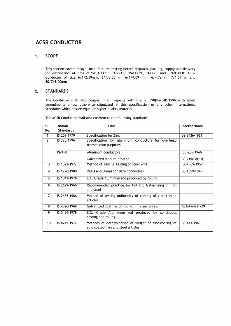
ACSR CONDUCTOR 1. SCOPE This section covers design, manufacture, testing before dispatch, packing, supply and delivery for destination of Kms of ―WEASEL‖ " RABBIT", "RACOON", "DOG", and "PANTHER" ACSR Conductor of size 6/1/2.59mm, 6/1/3.35mm, 6/1/4.09 mm, 6/4.72mm, 7/1.57mm and 30/7/3.00mm 2. STANDARDS The Conductor shall also comply in all respects with the IS: 398(Part-II)-1996 with latest amendments unless otherwise stipulated in this specification or any other International Standards which ensure equal or higher quality material. The ACSR Conductor shall also conform to the following standards. Sl. No. Indian Standards Title International 1 IS:209-1979 Specification for Zinc BS-3436-1961 2 IS:398-1996 Specification for aluminum conductors for overhead transmission purposes. Part-II Aluminum conductors IEC-209-1966 Galvanized steel reinforced BS-215(Part-II) 3 IS:1521-1972 Method of Tensile Testing of Steel wire ISO/R89-1959 4 IS:1778-1980 Reels and Drums for Bare conductors BS-1559-1949 5 IS:1841-1978 E.C. Grade Aluminum rod produced by rolling 6 IS:2629-1966 Recommended practice for Hot Dip Galvanizing of iron and steel 7 IS:2633-1986 Method of testing uniformity of coating of zinc coated articles. 8 IS:4826-1968 Galvanized coatings on round steel wires. ASTM A472-729 9 IS:5484-1978 E.C. Grade Aluminium rod produced by continuous casting and rolling. 10 IS:6745-1972 Methods of determination of weight of zinc-coating of zinc coated iron and steel articles BS-443-1969
Transcript
ACSR CONDUCTOR
1. SCOPE
This section covers design, manufacture, testing before dispatch, packing, supply and delivery
for destination of Kms of ―WEASEL‖ " RABBIT", "RACOON", "DOG", and "PANTHER" ACSR
Conductor of size 6/1/2.59mm, 6/1/3.35mm, 6/1/4.09 mm, 6/4.72mm, 7/1.57mm and
30/7/3.00mm
2. STANDARDS
The Conductor shall also comply in all respects with the IS: 398(Part-II)-1996 with latest
amendments unless otherwise stipulated in this specification or any other International
Standards which ensure equal or higher quality material.
The ACSR Conductor shall also conform to the following standards.
Sl.
No.
Indian
Standards
Title International
1 IS:209-1979 Specification for Zinc BS-3436-1961
2 IS:398-1996 Specification for aluminum conductors for overhead
transmission purposes.
Part-II Aluminum conductors IEC-209-1966
Galvanized steel reinforced BS-215(Part-II)
3 IS:1521-1972 Method of Tensile Testing of Steel wire ISO/R89-1959
4 IS:1778-1980 Reels and Drums for Bare conductors BS-1559-1949
5 IS:1841-1978 E.C. Grade Aluminum rod produced by rolling
6 IS:2629-1966 Recommended practice for Hot Dip Galvanizing of iron
and steel
7 IS:2633-1986 Method of testing uniformity of coating of zinc coated
articles.
8 IS:4826-1968 Galvanized coatings on round steel wires. ASTM A472-729
9 IS:5484-1978 E.C. Grade Aluminium rod produced by continuous
casting and rolling.
10 IS:6745-1972 Methods of determination of weight of zinc-coating of
zinc coated iron and steel articles
BS-443-1969
New Initiative on Material Mobilisation 170 Report of Committee A
Offersconforming to standards other than IS-398 shall be accompanied by the English
version of relevant standards in support of the guaranteed technical particulars to be
furnished as per format enclosed.
3. GENERAL TECHNICAL REQUIREMENTS
The General Technical Requirements are given in Section-II. The Conductor shall conform to
these technical requirements.
The Bidder shall furnish guaranteed technical particulars in Section-III.
3.1. MATERIALS/WORKMANSHIP
3.1.1. The material offered shall be of best quality and workmanship. The steel coredaluminum
conductor strands shall consist of hard drawn aluminium wire manufactured from not less
than 99.5% pure electrolytic aluminium rods of E.C. grade and copper content not exceeding
0.04%. They shall have the same properties and characteristics as prescribed in IEC: 889-
1987. The steel wire shall be made from material produced either by the acid or basic open
hearth process or by electric furnace process or basic oxygenprocess. Steel wire drawn from
Bessemer process shall not be used.
3.1.2. The steel wires shall be evenly and uniformly coated with electrolytic high grade, 99.95%
purity zinc complying with the latest issue of IS-209 for zinc. The uniformity of zinc coating
and the weight of coating shall be in accordance with Section-II and shall be tested and
determined according to the latest IS-2633 or any other authoritative standard.
3.1.3. The steel strands shall be hot dip galvanized and shall have a minimum zinc coating of 250
gm/sq.m after stranding. The coating shall be smooth, continuous, and of uniform
thickness,free from imperfections and shall withstand minimum three dips after stranding in
standard preece test. The steel strands shall be preformed and postformed in order to
prevent spreading of strands in the event of cutting of composite core wire. The properties
and characteristics of finished strands and individual wires shall be as prescribed in IEC: 888-
1987.
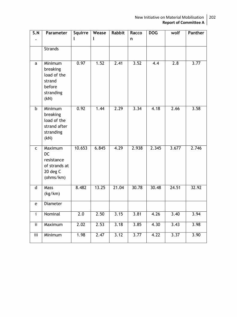
4. CONDUCTOR PARAMETERS
The Parameters of individual strands and composite steel coredaluminumconductor, shall be
in accordance with the values given in Section-II.
Creep in a conductor is attributed partly due to settlement of strands and partly due to
non-elastic elongation of metal when subjected to load. The manufacturer of conductor
shall furnish the amount of creep which will take place in 10, 20, 30, 40 and 50 years along
with the supporting calculations. The calculations should be based on everyday temperature
of 32 ºC and everyday tension of 25% of UTS of conductor of 11/33 KV Lines.
5. TOLERANCES
The tolerances on standard diameter of Aluminum and Steel wires shall be as detailed in
specific technical requirements.
The cross-section of any wire shall not depart from circularity by more than an amount
corresponding to the tolerance on the standard diameter.
The details of diameters, lay ratios of Aluminum and steel wires shall be in accordance with
the Section-II "Technical Requirements".
6. SURFACE CONDITIONS
New Initiative on Material Mobilisation 171 Report of Committee A
All aluminum and steel strands shall be smooth, and free from all imperfections, spills/and
splits. The finished conductor shall be smooth, compact, uniform and free from all
imperfections including spills and splits, die marks, scratches, abrasions, scuff marks, kinks
pressure and/or unusual bangle noise on tapping, material inclusions, white rust, powder
formation or black spots (on account of reaction with trapped rain water etc.,), dirt, grit,
etc. The surface of conductor shall be free from points, sharp edges, abrasions or other
departures from smoothness or uniformity of surface contour that would increase radio
interference and corona losses. When subjected to tension upto 50% of the ultimate
strength of the conductor, the surface shall not depart from the cylindrical form nor any
part of the component parts or strands move relative to each other in such a way as to get
out of place and disturb the longitudinal smoothness of the conductor.
7. JOINTS IN WIRES
7.1. Aluminum wires
During stranding, no aluminum wire welds shall be made for the purpose of achieving the
required conductor length.
No joint shall be permitted in the individual aluminum wires in the outer most layer of the
finished Conductor. However, joints in the 12 wire & 18 wire inner layer of the conductor
are permitted but these joints shall be made by the cold pressure butt welding and shall be
such that no two such joints shall be within 15 meters of each other in the complete
stranded conductor.
7.2. Steel wires
There shall be no joints in finished steel wires forming the core of the steel reinforced
aluminum conductor.
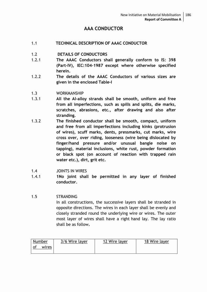
8. STRANDING
The wires used in construction of the stranded conductor, shall, before stranding, satisfy all
requirements of IS-398 (Part-II) 1996.
In all constructions, the successive layers shall be stranded in opposite directions. The wires
in each layer shall be evenly and closely stranded round the underlying wire or wires. The
outer most layer of wires shall have a right hand lay. The lay ratio of the different layers
shall be within the limits given under Section-II.
9. PACKING
9.1. The conductor shall be supplied in non-returnable strong wooden drums provided with
lagging of adequate strength constructed to protect the conductor against any damage and
displacement during transit, storage and subsequent handling and stringing operations in the
field. The drums shall generally conform to IS-1778-1980 and latest version except as
otherwise specified hereinafter. The conductor drums shall be adequate to wind one
standard length of 2500 meters of WEASEL/RABIT/RACOON/DOG/PANTHERACSR conductor.
9.2. The drums shall be suitable for wheel mounting and for letting off the conductor under a
minimum controlled tension of the order of 5KN. The conductor drums shall be provided with
necessary clamping arrangements so as to be suitable for tension stringing of power
conductor.
9.3. The bidders should submit their drawings of the conductor drums along with the bid. After
placement of letter of intent the Manufacturer shall submit four copies of fully dimensioned
New Initiative on Material Mobilisation 172 Report of Committee A
drawing of the drum for Employer's approval. After getting approval from the Employer,
Manufacturer shall submit 30 more copies of the approved drawings for further distribution
and field use.
9.4. All wooden components shall be manufactured out of seasoned soft wood free from defects
that may materially weaken the component parts of the drums. Preservative treatment for
anti-termite/anti fungus shall be applied to the entire drum with preservatives of a quality
which is not harmful to the conductor.
9.5. All flanges shall be 2-ply construction with 64 mm thickness. Each ply shall be nailed and
clenched together at approximately 90 degrees. Nails shall be driven from the inside face of
the flange, punched and then clenched on the outer face. Flange boards shall not be less
than the nominal thickness by more than 2 mm. There shall not be less than 2 nails per board
in each circle.
9.6. The wooden battens used for making the barrel of the conductor shall be of segmental type.
These shall be nailed to the barrel supports with at least two nails. The battens shall be
closely butted and shall provide a round barrel with smooth external surface. The edges of
the battens shall be rounded or chamfered to avoid damage to the conductor.
9.7. Barrel studs shall be used for construction of drums. The flanges shall be holed and the
barrel supports slotted to receive them. The barrel studs shall be threaded over a length on
either end, sufficient to accommodate washers, spindle plates and nuts for fixing flanges at
the required spacing.
9.8. Normally, the nuts on the studs shall stand protruded of the flanges. All the nails used on the
inner surface of the flanges and the drum barrel shall be countersunk. The ends of the barrel
shall generally be flushed with the top of the nuts.
9.9. The inner cheek of the flanges and drum barrel surface shall be painted with bitumen based
paint.
9.10. Before reeling, card board or double corrugated or thick bituminized waterproof bamboo
paper shall be secured to the drum barrel and inside of flanges of the drum by means of a
suitable commercial adhesive material. The paper should be dried before use. Medium grade
craft paper shall be used in between the layers of the conductor. After reeling the conductor
the exposed surface of the outer layer of conductor shall be wrapped with thin polythene
sheet across the flanges to preserve the conductor from dirt, grit and damage during
transportation and handling and also to prevent ingress of rain water during
storage/transport.
9.11. A minimum space of 75 mm shall be provided between the inner surface of the external
protective lagging and outer layer of the conductor. Outside the protective lagging, there
shall be minimum of two binders consisting of hoop iron/galvanised steel wire. Each
protective lagging shall have two recesses to accommodate the binders.
9.12. Each batten shall be securely nailed across grains as far as possible to the flange edges with
at least 2 nails per end. The length of the nails shall not be less than twice the thickness of
the battens. The nail shall not protrude above the general surface and shall not have
exposed sharp edges or allow the battens to be released due to corrosion.
9.13. The conductor ends shall be properly sealed and secured with the help of U-nails on one side
of the flanges.
9.14. Only one standard length of conductor shall be wound on each drum. The method of lagging
to be employed shall be clearly stated in the tender.
9.15. As an alternative to wooden drum Bidder may also supply the conductors in non-returnable
New Initiative on Material Mobilisation 173 Report of Committee A
painted steel drums. The painting shall conform to IS:9954-1981,reaffirmed in 1992.
Wooden/ steel drum will be treated at par for evaluation purpose and accordingly the Bidder
should quote the package.
10. LABELLING AND MARKING
The drum number shall be branded or gauged or stencilled into the flange. An arrow shall
be marked on the sides of the drum, together with the words "Roll this way". Each drum
shall have the following information provided on the outside of the flange stencilled with
indelible ink.
i) Manufacturer's name and address. ii) Contract/Specification number. iii) Size and type of conductor.
iv) Net weight of the conductor. v) Gross weight of the conductor and drum. vi) Length of the conductor. vii) Position of the conductor end. viii) Drum and lot number. ix) Name and address of the consignee. x) Month and year of manufacture. xi) The drum may also be marked with standard specification as per which the conductor
is manufactured.
11. STANDARD LENGTHS
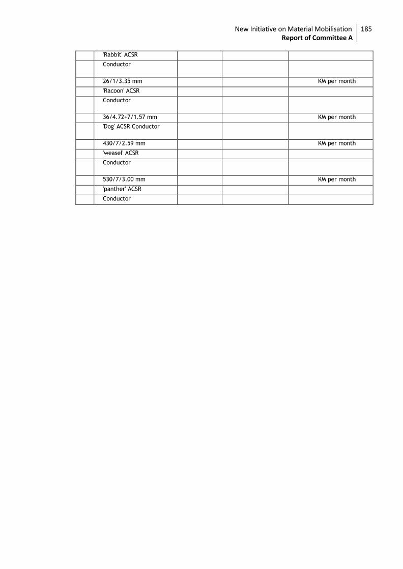
11.1. The standard length of the conductor shall be 2500 metres. Bidder shall indicate the
standard length of the conductor to be offered by them. A tolerance of plus or minus 5% on
the standard length offered by the bidder shall be permitted. All lengths outside this limit of
tolerance shall be treated as random lengths.
11.2. Random lengths will be accepted provided no length is less than 70% of the standard length
and total quantity of such random length shall not be more than 10% of the total quantity
order. When one number random length has been manufactured at any time, five (5) more
individual lengths, each equivalent to the above random length with a tolerance of +/-5%
shall also be manufactured and all above six random lengths shall be dispatched in the same
shipment. At any point, the cumulative quantity supplied including such random lengths shall
not be more than 12.5% of the total cumulative quantity supplied including such random
lengths. However, the last 20% of the quantity ordered shall be supplied only in standard
length as specified.
11.3. Bidder shall also indicate the maximum single length, above the standard length, he can
manufacture in the guaranteed technical particulars of offer. This is required for special
stretches like river crossing etc. The Employer reserves the right to place orders for the
above lengths on the same terms and conditions applicable for the standard lengths during
the pendency of the Contract.
12. QUALITY ASSURANCE PLAN
A Quality Assurance Plan including customer hold points covering the manufacturing
activities of the material shall be required to be submitted by the tenderer to the Employer
along with the tender. The Quality Assurance Plan after the same is found acceptable, will
be approved by the Employer.
The contractor shall follow the approved Quality Assurance Plan in true spirit. If desired by
the Employer, he shall give access to all the documents and materials to satisfy the Employer
that the Quality Assurance Plan is being properly followed.
New Initiative on Material Mobilisation 174 Report of Committee A
13. TESTING
13.1. SELECTION OF TEST SAMPLES FOR TYPE TESTS
13.1.1. The samples shall be taken from a continuous length of conductor and subjected to all the
tests specified in clause 14.
13.2. SELECTION OF TEST SAMPLES FOR ACCEPTANCE TESTS
13.2.1. Before dispatch from the works individual wire and finished steel coredaluminum conductor
shall be subjected to the tests as specified in IS:398 or any other authoritative standard.
13.2.2. Sample for individual wires for test shall be taken before stranding from outer ends of not
less than ten per cent of the spools in the case of aluminum wire and ten per cent of the
wire coils in the case of steel wires. If samples are taken after stranding, they shall be
obtained by cutting 1.2 meters from the outer ends of the finished conductor from not more
than 10 per cent of the finished reels.
13.2.3. The routine tests shall be same as acceptance test and shall be carried out on each coil.
14. TESTS
The following tests shall be carried out on sample/samples of conductor.
14.1 Type Tests
(i) Visual examination
(ii) Measurement of diameters of individual aluminum and steel wires.
(iii) Measurement of lay ratio of each layer
(iv) Breaking load test
(v) Ductility test
(vi) Wrapping test
(vii) Resistance test on aluminum wires.
(viii) DC resistance Test on Composite Conductor.
(ix) Galvanizing test
(x) Surface condition test
(xi) Stress Strain test
(xii) Procedure qualification test on welded joint of Aluminum Strands.
NOTE:-The type test reports shall not be older than FIVE years and shall be valid up to
expiry of validity of offer.
The above additional lists if not conducted earlier, shall be done under the subject
project package at no extra cost.
14.2 Acceptance tests and Routine tests
(ii) Visual and dimensional check on drum.
(iii) Visual examination
(iv) Measurement of diameters of individual aluminum and steel wires.
(v) Measurement of lay ratio of each layer
(vi) Breaking load test
(vii) Ductility test
(viii) Wrapping test
(ix) Resistance test on aluminum wires.
(x) DC resistance Test on Composite Conductor.
(xi) Galvanizing test
14.3 Tests During Manufacture
New Initiative on Material Mobilisation 175 Report of Committee A
The following tests during manufacture shall be carried out.
(i) Chemical analysis of zinc used for galvanising, (ii) Chemical analysis of aluminum used for making aluminumstrands, (iii) Chemical analysis of steel used for making steel strands,
14.4 Visual examination
The conductor shall be examined visually for good workmanship and general surface finish
of the conductor. The conductor drums shall be rewound in the presence of Inspecting
Officer. The Inspector will initially check for Scratches, Joints etc., and that the
conductor shall generally conform to the requirements of the specifications/IS 398(Part-
II)-1996.
14.5 Measurement of diameters of individual Aluminum and Steel Wires.
The diameters of individual Aluminum and Steel Wires shall be checked to ensure that
they conform to the requirements of this specification.
14.6 Measurement of lay-ratios
The lay-ratios of each layer of the conductor shall be measured and checked to ensure
that they conform to the requirements of this specification and IS:398 (Part-II)-1996.
14.7 Breaking load test
a) Breaking load test on complete conductor.
Circles perpendicular to the axis of the conductor shall be marked at two places on a
sample of conductor of minimum 5m length between fixing arrangement suitably fixed on
a tensile testing machine. The load shall be increased at a steady rate upto 50% of
minimum specified UTS and held for one minute. The circles drawn shall not be distorted
due to relative movement of strands. Thereafter the load shall be increased at steady
rate to 100% of UTS and held for one minute. The Conductor sample shall not fail during
this period. The applied load shall then be increased until the failing load is reached and
the value recorded.
b) Breaking load test on individual Aluminum and Galvanized steel wires.
This test shall be conducted on both Aluminum and Galvanized steel wires. The breaking
load of one specimen cut from each of the samples taken shall be determined by means
of suitable tensile testing machine. The load shall be applied gradually and the rate of
separation of the jaws of the testing machine shall be not less than 25 mm/min. and not
greater than 100 mm. / min. The ultimate breaking load of the specimens shall be not
less than the values specified in the Section-II.
14.8 Ductility Test
For the purpose of this test both torsion and elongation tests shall be carried out on
galvanized steel wires only.
14.9 Torsion Test
One specimen cut from each of the samples taken shall be gripped in two vices exactly 15
cms. apart. One of the vices shall be made to revolve at a speed not exceeding one
revolution per second and the other shall be capable of moving longitudinally to allow for
contraction or expansion during testing. A small tensile load not exceeding 2 (two)
New Initiative on Material Mobilisation 176 Report of Committee A
percent of the breaking load of the wire shall be applied to the samples during testing.
The test shall be continued until fracture occurs and the fracture shall show a smooth
surface at right angles to the axis of the wire. After fracture, the specimen shall be free
from helical splits. The sample shall withstand a number of twists equivalent to not less
than 18 on length equal to 100 times the diameter. When twisted after stranding the
number of complete twists before fracture occurs shall be not less than 16 on a length
equal to 100 times the diameter of the wire. In case test sample length is less or more
than 100 times the stranded diameter of the strand, the minimum number of twists will
be proportioned to the length and if number comes in the fraction then it will be rounded
off to the next higher whole number. The fracture shall show a smooth surface at right
angles to the axis of the wire.
14.10 Elongation Test
The elongation of one specimen cut from each of the samples taken shall be determined.
The specimen shall be straightened by hand and an original gauge length of 200 mm. shall
be marked on the wire. A tensile load shall be applied as described in 1.1.4.6.2.1 and the
elongation shall be measured after the fractured ends have been fitted together. If the
fracture occurs outside the gauge marks, or within 25 mm. of either mark and the
required elongation is not obtained, the test shall be disregarded and another test
conducted. When tested before stranding, the elongation shall be not less than 4 percent
and when tested after stranding, the elongation shall be not less than 3.5 percent.
14.11 Wrapping Test
This test shall be conducted on both Aluminum and Galvanized steel wires.
14.11.1 Aluminum wires
One specimen cut from each of the samples of aluminum wires shall be wrapped round a
wire of its own diameter to form a close helix of 8 turns. Six turns shall then be
unwrapped and closely wrapped in the same direction as before. The wire shall not break
or show any crack.
14.11.2 Galvanized steel wires
One specimen cut from each of the samples of galvanized steel wire taken shall be
wrapped round a mandrel of diameter equal to 4 times the wire diameter to form a close
helix of 8 turns. Six turns shall then be unwrapped and again closely wrapped in the same
direction as before. The wire shall not break.
14.12 Resistance Test
This test shall be conducted on aluminum wires only, conforming to procedure as per
IEC:889. The electrical resistance of one specimen of aluminum wire cut from each of the
samples taken shall be measured at ambient temperature. The measured resistance shall
be corrected to the value corresponding to 20 degrees C. by means of following formula.
1
R20 = RT------------------------
1+ alpha x (T-20)
Where
R20 = Resistance corrected at 20 degrees C.
New Initiative on Material Mobilisation 177 Report of Committee A
RT = Resistance measured at T degrees C.
alpha = Constant mass temperature coefficient ofresistance 0.004.
T = Ambient temperature during measurement
This resistance calculated to 20 degrees C. shall be not more than the maximum value
specified in section-II.
14.13 Galvanizing Test
This test shall be conducted on galvanized steel wires only. The uniformity of Zinc coating
and the weight of coating shall be in accordance with IS 4826-1979.
14.14 Surface Condition Test
A sample of the finished conductor for use in 11/33 KV system having a minimum length
of 5 meters with compression type dead end clamps compressed on both ends in such
manner as to permit the conductor to take its normal straight line shape, shall be
subjected to a tension of 50 percent of the UTS of the conductor. The surface shall not
depart from its cylindrical shape nor shall the strands move relative to each other so as to
get out of place or disturb the longitudinal smoothness of conductor. The measured
diameter at any place shall be not less than the sum of the minimum specified diameters
of the individual aluminum and steel strands as indicated in Section-II.
14.15 Stress-Strain Test
The test is contemplated only to collect the creep data of the conductor from the
manufacturer. A sample of conductor of minimum 10 meters length shall be suitably
compressed with dead end clamps.
15. TEST SET-UP
15.1. The test sample shall be supported in a trough over its full length and the trough adjusted
so that theconductor will not be lifted by more than 10mm under tension. This shall be
ascertained by actual measurement.
15.2. The distance between the clamp and the sleeve mouth shall be monitored with callipers
during the test to ensure that, after the test, it does not change by more than 1mm +
0.1mm from the value before the test.
15.3. The conductor strain shall be evaluated from the measured displacements at the two ends
of the gauge length of the sample. The gauge reference targets shall be attached to the
clamps which lock the steel and aluminum wires together. Target plates may be used with
dial gauges or displacement transducers and care shall be taken to position the plates
perpendicular to the conductor. Twisting the conductor, lifting it and moving it from side-
to-side by the maximum amounts expected during the test should introduce no more than
0.3mm error in the reading.
16. TEST LOADS FOR COMPLETE CONDUCTOR
The loading conditions for repeated stress-strain tests for complete conductor shall be as
follows:
16.1. 1KN load shall be applied initially to straighten the conductor. The load shall be removed
after straightening and then the strain gauges are to be set At zero tension.
16.2. For non-continuous stress-strain data, the strain readings at 1KN intervals at lower
tensions and 5 KN intervals above 30% of UTS shall be recorded.
16.3. The sample shall be reloaded to 30% of UTS and held for 1 hour. Readings are to be noted
after 5, 10, 15, 30, 45 and 60 minutes during the hold period. The load shall be released
then after the hold period.
New Initiative on Material Mobilisation 189 Report of Committee A
16.4. The sample shall be reloaded to 50% of UTS and held for 1 hour. Readings are to be noted
after 5, 10, 15, 30, 45 and 60 minutes during the hold period. The load shall be released
then after the hold period.
16.5. Reloading upto 70% of UTS shall be done and held for 1 hour. Readings are to be noted
after 5, 10, 15, 30, 45 and 60 minutes. The load shall be released.
16.6. Reloading upto 85% of UTS shall be done and held for 1 hour. Readings are to be noted
after 5, 10,15, 30, 45 and 60 minutes and the load shall be released then.
16.7. Tension shall be applied again and shall be increased uniformly until the actual breaking
strength is reached. Simultaneous readings of tension and elongation shall be recorded
upto 90% of UTS at the intervals described under Clause 16.6.
17. TEST LOADS FOR STEEL CORE ONLY
The loading conditions for repeated stress-strain tests for the steel core of ACSR shall be
as follows:
17.1. The test shall consist of successive applications of load applied in a manner similar to that
for the complete conductor at 30%, 50%, 70% and 85% of UTS.
17.2. The steel core shall be loaded until the elongation at the beginning of each hold period
corresponds to that obtained on the complete conductor at 30%, 50%, 70% and 85% of UTS
respectively.
18. STRESS-STRAIN CURVES
The design stress-strain curve shall be obtained by drawing a smooth curve through the
0.5 and 1 hour points at 30%,50% and 70% of UTS loadings. The presence of any aluminum
slack that can be related to any observed extrusion entering the span from the
compression dead ends shall be removed from the lower ends of the design curves. Both
the laboratory and standard stress-strain curves shall be submitted to the
Employeralongwith test results. The stress-strain data obtained during the test shall be
corrected to the standard temperature i.e. 20 deg.C.
19. DC RESISTANCE TEST ON COMPOSITE CONDUCTOR
On a conductor sample of minimum 5m length, two contact clamps shall be fixed with a
pre-determined bolt torque. The resistance of the sample shall be measured by a Kelvin
double bridge by placing the clamps initially zero meter and subsequently one meter
apart. The test shall be repeated at least five times and the average value recorded. The
value obtained shall be corrected to the value at 20 deg C as per clause no. 12.8 of IS:398
(Part-II)-1982/1996.The corrected resistance value at 20 deg.C shall conform to the
requirements of this specification.
20. PROCEDURE QUALIFICATION TEST ON WELDED ALUMINUM STRANDS.
Two Aluminum wires shall be welded as per the approved quality plan and shall be
subjected to tensile load. The breaking strength of the welded joint of the wire shall not
be less than the guaranteed breaking strength of individual strands.
21. CHEMICAL ANALYSIS OF ALUMINUM AND STEEL
Samples taken from the Aluminum and Steel ingots / coils/ strands shall be chemically/
spectrographicallyanalyzed. The same shall be in conformity with the requirements stated
in this specification.
New Initiative on Material Mobilisation 199 Report of Committee A
22. CHEMICAL ANALYSIS OF ZINC
Samples taken from the zinc ingots shall be chemically / spectrographically analysed.The
same shall be in conformity with the requirements stated in this specification.
23. VISUAL AND DIMENSIONAL CHECK ON DRUMS
The drums shall be visually and dimensionally checked to ensure that they conform to the
requirements of this specification.
24. REJECTION AND RETEST
24.1. In case of failure in any type test, the Manufacturer is either required to manufacture
fresh sample lot and repeat all the tests successfully once or repeat that particular type
test three times successfully on the sample selected from the already manufactured lot at
his own expenses. In case a fresh lot is manufactured for testing then the lot already
manufactured shall be rejected.
24.2. If samples are taken for test after stranding and if any selected reel fails in the retest, the
manufacturer may test each and every reel and submit them for further inspection. All
rejected material shall be suitably marked and segregated.
25. CHECKING AND VERIFICATION OF LENGTH OF CONDUCTOR
The contractor should arrange for inspection by the representative of the Employer
specially authorised for this purpose. At least 50% of the total number of drums of
conductor subject to minimum of two taken at random should be checked to ascertain
the length of conductor. Arrangements should be made available in the works of the
manufacturer for transferring the conductor from one reel to another at the same time
measuring the length of the conductor so transferred by means of a meter.
26. ADDITIONAL TESTS
The Employer reserves the right of having at his own expenses any other test(s) of
reasonable nature carried out at Bidder's premises, at site, or in any other standard
Laboratory in addition to the aforesaid type, acceptance and routine tests to satisfy
himself that the materials comply with the specifications.
27. TESTING EXPENSES
27.1. The breakup of the testing charges for the type tests specified shall be indicated
separately.
27.2. Bidder shall indicate the laboratories in which they propose to conduct the type test. They
shall ensure that adequate facilities are available in the laboratories and the tests can be
completed in these laboratories within the time schedule guaranteed by them.
27.3. The entire cost of testing for the acceptance and routine tests and tests during
manufacture specified herein shall be treated as included in the quoted unit price of the
conductor, except for the expenses of the inspector/Employer's representative.
27.4. In case of failure in any type test, if repeat type tests are required to be conducted then
New Initiative on Material Mobilisation 180 Report of Committee A
all the expenses for deputation of Inspector/Employer's representative shall be deducted
from the contract price. Also if on receipt of the Manufacturer's notice of testing, the
Employer's representative does not find 'plant' to be ready for testing, the expenses
incurred by the Employer for redeputation shall be deducted from contract price.
28. TEST REPORTS
28.1. Copies of type test reports shall be furnished in at least six copies alongwith one original.
One copy will be returned duly certified by the Employer only after which the commercial
production of the material shall start.
28.2. Record of Routine test reports shall be maintained by the Manufacturer at his works for
periodic inspectionby the Employer's representative.
28.3. Test certificates of Tests during manufacture shall be maintained by the Manufacturer.
These shall be produced for verification as and when desired by the Employer.
29. TEST FACILITIES
The following additional test facilites shall be available at the Manufacturer's works:
(i) Calibration of various testing and measuring equipment including tensile testing
(ii) Standard resistance for calibration of resistance bridges.
(iii) Finished Conductor shall be checked for length verification and surface finish on
separate rewinding machine at reduced speed(variable from 8 to 16 meters per minute).The rewinding facilities shall have appropriate clutch system and be
free of vibrations, jerks etc with traverse laying facilities.
30. INSPECTION
30.1. The Employer's representative shall, at all times, be entitled to have access to the works
and all places of manufacture where conductor shall be manufactured and the
representative shall have full facilities for unrestricted inspection of the Bidder's works,
raw materials and process of manufacture and conducting necessary tests as detailed
herein.
30.2. The Bidder shall keep the Employer informed in advance of the time of starting and of the
progress of manufacture of conductor in its various stages so that arrangements can be
made for inspection.
30.3. The contractor will intimate the Employer about carrying out of the tests at least 45 days
in advance of the scheduled date of tests during which the Employer will arrange to
depute his representative/s to be present at the time of carrying out of the tests. Six (6)
copies of the test reports shall be submitted.
30.4. No material shall be dispatched from its point of manufacture before it has been
satisfactorily inspected and tested, Unless the inspection is waived off by the employer in
writing. In the later case also, the conductor shall be dispatched only after satisfactory
testing for all tests specified herein has been completed and approved by the employer.
30.5. The acceptance of any quantity of material shall in no way relieve the Bidder of any of his
responsibilities for meeting all requirements of the specification, and shall not prevent
subsequent rejection if such material is later found to be defective.
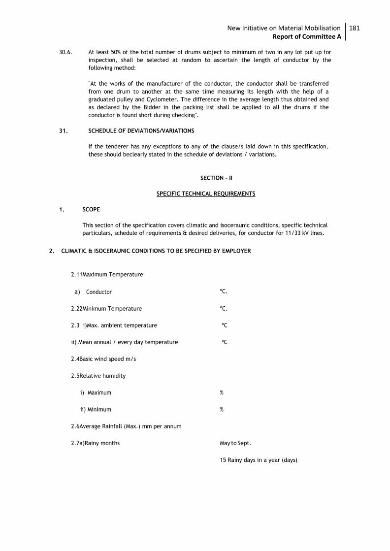
New Initiative on Material Mobilisation 181 Report of Committee A
30.6. At least 50% of the total number of drums subject to minimum of two in any lot put up for
inspection, shall be selected at random to ascertain the length of conductor by the
following method:
"At the works of the manufacturer of the conductor, the conductor shall be transferred
from one drum to another at the same time measuring its length with the help of a
graduated pulley and Cyclometer. The difference in the average length thus obtained and
as declared by the Bidder in the packing list shall be applied to all the drums if the
conductor is found short during checking".
31. SCHEDULE OF DEVIATIONS/VARIATIONS
If the tenderer has any exceptions to any of the clause/s laid down in this specification,
these should beclearly stated in the schedule of deviations / variations.
SECTION - II
SPECIFIC TECHNICAL REQUIREMENTS
1. SCOPE
This section of the specification covers climatic and isoceraunic conditions, specific technical
particulars, schedule of requirements & desired deliveries, for conductor for 11/33 kV lines.
2. CLIMATIC & ISOCERAUNIC CONDITIONS TO BE SPECIFIED BY EMPLOYER
2.1 1Maximum Temperature
a) Conductor ºC.
2.2 2Minimum Temperature ºC.
2.3 i)Max. ambient temperature ºC
ii) Mean annual / every day temperature ºC
2.4Basic wind speed m/s
2.5 Relative humidity
i) Maximum %
ii) Minimum %
2.6 Average Rainfall (Max.) mm per annum
2.7 a)Rainy months May to Sept.
15 Rainy days in a year (days)
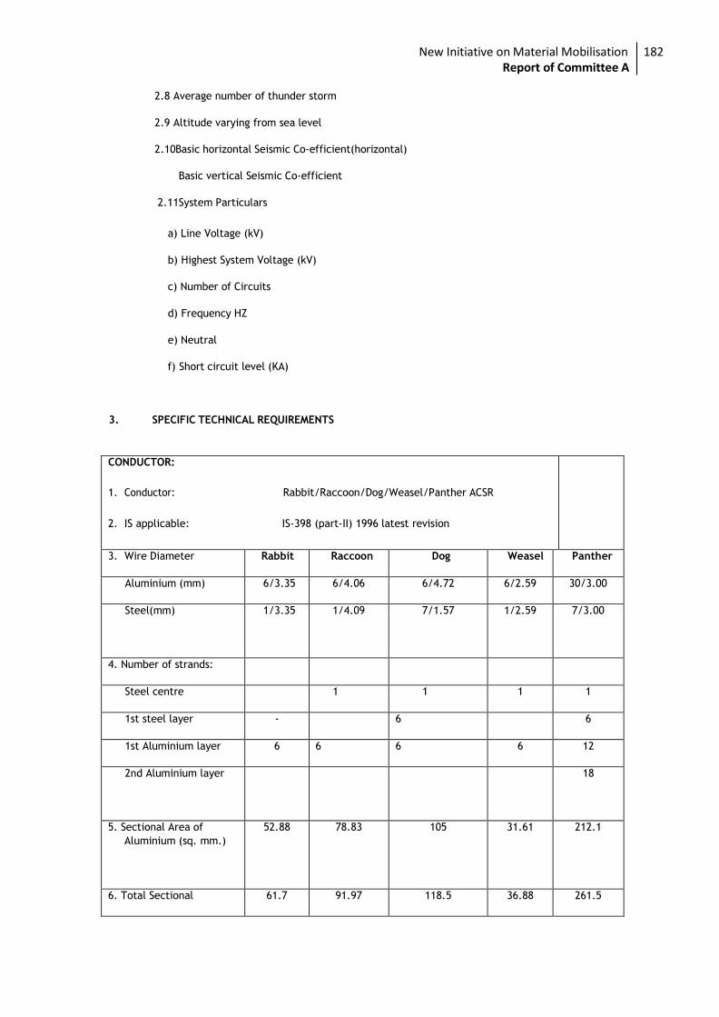
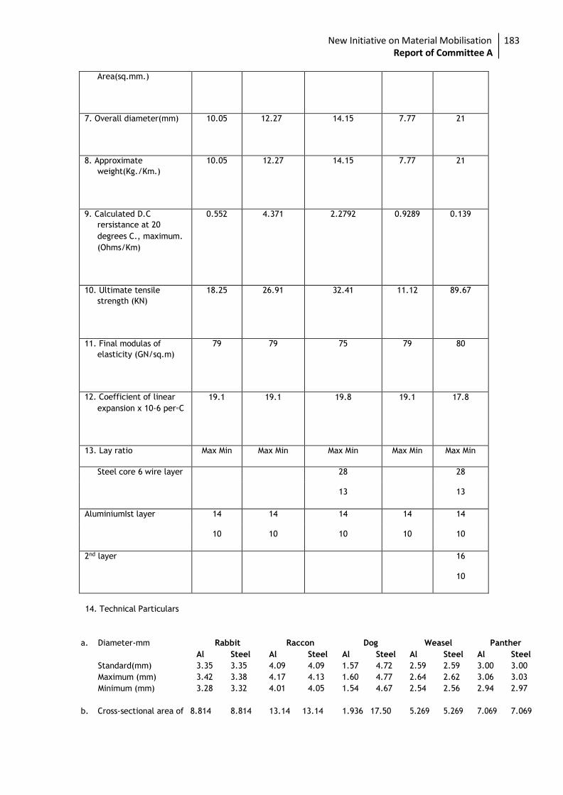
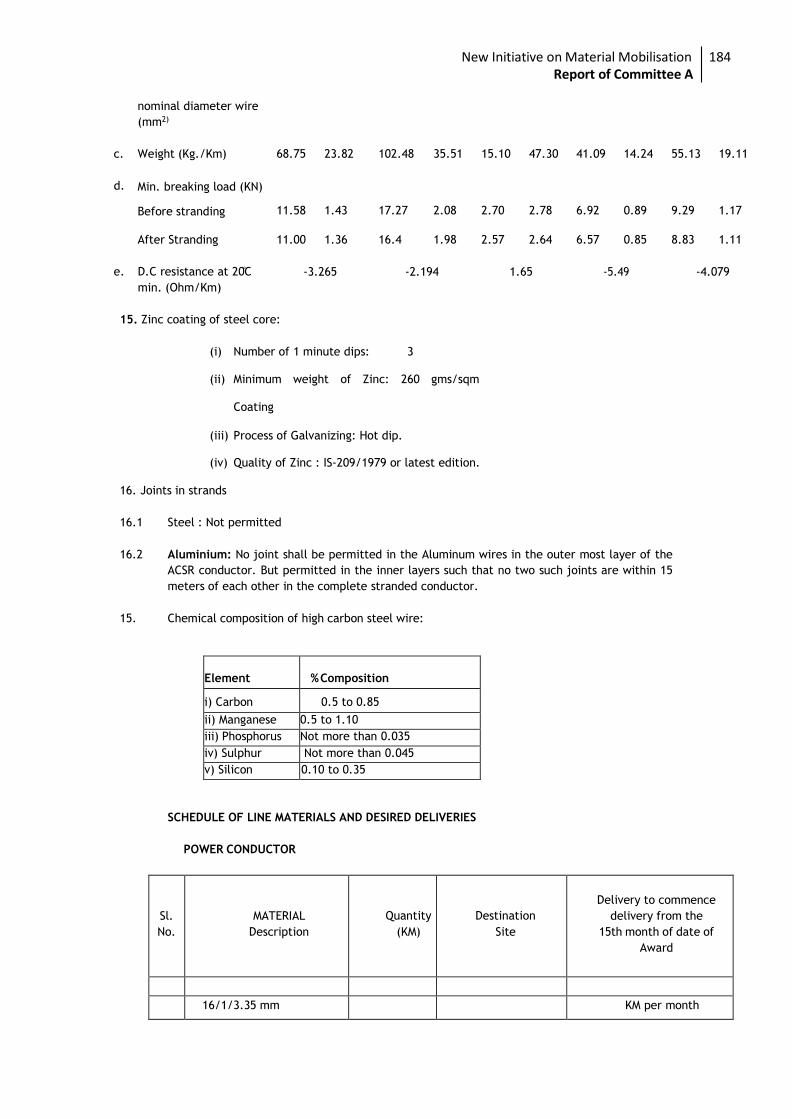
New Initiative on Material Mobilisation 182 Report of Committee A