Page 1
MANUAL - Fire Risk Management
BE2 Suppression Systems October 2010 MBB Page 1 of 37
Suppression Systems
Contents
Suppression Agents ........................................................................................................... 5
Fire Suppression ............................................................................................................ 5
Natural Suppression ....................................................................................................... 5
Water ............................................................................................................................. 5
Foam .............................................................................................................................. 6
Factors Affecting Foam Effectiveness ............................................................................ 6
Design Codes for Foam.................................................................................................. 7
Gaseous Systems .......................................................................................................... 7
Halon systems ................................................................................................................ 7
Gas Flooding .................................................................................................................. 7
Life Safety Considerations .............................................................................................. 8
Carbon Dioxide .............................................................................................................. 8
Automatic Sprinkler Systems ............................................................................................. 9
Purpose .......................................................................................................................... 9
Reliability ........................................................................................................................ 9
Sprinkler Head Operation ............................................................................................... 9
Sprinkler Heads .............................................................................................................. 9
Type of Heads ...............................................................................................................10
Head Operation .............................................................................................................10
Entrainment Process .....................................................................................................10
Response Time Index ...................................................................................................10
Speed of Operation .......................................................................................................12
New Zealand Standards for Sprinklers ..........................................................................12
Commercial Sprinkler Systems .........................................................................................13
Definition .......................................................................................................................13
Sprinkler Installation ......................................................................................................13
Advantages ...................................................................................................................13
Sprinklers for Houses ........................................................................................................14
Introduction ...................................................................................................................14
Independent System .....................................................................................................14
Releas
ed un
der th
e Offic
ial In
formati
on A
ct
Page 2
MANUAL - Fire Risk Management
BE2 Suppression Systems October 2010 MBB Page 2 of 37
Combination System .....................................................................................................14
Suitability .......................................................................................................................14
Related Documents .......................................................................................................14
Terminology ......................................................................................................................15
Assumed area of operation ...........................................................................................15
Authority having jurisdiction ...........................................................................................15
Cut off sprinkler .............................................................................................................15
Density of discharge ......................................................................................................15
Design flow....................................................................................................................15
Design pressure ............................................................................................................15
Design point ..................................................................................................................16
Seismic resistance ........................................................................................................16
Classes of occupancy ...................................................................................................16
Extra light hazard ..........................................................................................................16
Ordinary hazard ............................................................................................................16
Extra high hazard ..........................................................................................................16
High piling limits ............................................................................................................17
Fire hazard categories of materials ...............................................................................17
Process risk ...................................................................................................................17
Types of Systems .............................................................................................................18
Sprinkler System Categories .........................................................................................18
Conventional Systems .....................................................................................................19
Conventional Sprinkler Systems ....................................................................................19
Wet pipe system ............................................................................................................19
Wet pipe system design and coverage ..........................................................................19
Alternate wet and dry pipe system .................................................................................19
Composite valve ............................................................................................................19
Installation of Sprinklers ................................................................................................19
Dry Pipe System ...........................................................................................................20
Special conditions .........................................................................................................20
Tail end alternate wet and dry pipe system....................................................................20
Pre-Action System .........................................................................................................20
Operation of Pre-Action system .....................................................................................20
Detection Sprinklers Temperature rating .......................................................................20
Anti-freeze system .........................................................................................................20
Tail end anti-freeze system ...........................................................................................20
Alternate system ...........................................................................................................21
Releas
ed un
der th
e Offic
ial In
formati
on A
ct
Page 3
MANUAL - Fire Risk Management
BE2 Suppression Systems October 2010 MBB Page 3 of 37
Deluge Systems ................................................................................................................22
Deluge Systems ............................................................................................................22
Purpose .........................................................................................................................22
Deluge Sprayers ...........................................................................................................23
Deluge Spray Heads .....................................................................................................23
Multiple jet controls ........................................................................................................24
Main Components of Wet Systems ...................................................................................25
Key components ...........................................................................................................25
Sprinkler Room or House ..............................................................................................25
Main stop valve .............................................................................................................25
Alarm Gong Stop Valve .................................................................................................25
Test and Drain Valve .....................................................................................................26
Brigade Inlet Connection ...............................................................................................26
Brigade Booster Control Wheel .....................................................................................26
Towns Main Pressure Gauge ........................................................................................26
Alarm Valve Assembly ..................................................................................................26
Alarm Gong ...................................................................................................................26
Booster Pump Controls .................................................................................................27
Sprinklers ......................................................................................................................27
Glass Bulb Sprinkler Head Construction ........................................................................28
Fusible Link Sprinkler Head Construction ......................................................................28
Sprinkler Head Coding ..................................................................................................29
Other Types of sprinklers ..............................................................................................29
Sprayers ........................................................................................................................30
Sprinkler System Water Supplies - Types of Water Supply ..............................................31
Introduction ...................................................................................................................31
Primary Supply ..............................................................................................................31
Secondary Supply .........................................................................................................31
Protection of Towns Mains ............................................................................................31
Classes of Water Supply ...................................................................................................32
Classification .................................................................................................................32
Tank capacity ................................................................................................................32
Design Criteria ..............................................................................................................33
Early Suppression Fast Response: ESFR .....................................................................33
Water Mist .....................................................................................................................34
Entrainment of water droplets ........................................................................................34
Fire Brigade Systems - Fire Hydrant Systems for Buildings ..............................................35
Releas
ed un
der th
e Offic
ial In
formati
on A
ct
Page 4
MANUAL - Fire Risk Management
BE2 Suppression Systems October 2010 MBB Page 4 of 37
Fire Hydrant ..................................................................................................................35
Building Pumps .............................................................................................................35
Pre Inlet Pressure..........................................................................................................35
Outlet Pressure .............................................................................................................35
Flow Rate ......................................................................................................................35
Standard .......................................................................................................................35
Types of Systems .............................................................................................................36
Dry System....................................................................................................................36
Wet System ...................................................................................................................36
Charged System ...........................................................................................................36
Number of Outlets Required ..........................................................................................36
Measurement of Arc ......................................................................................................36
Protected Lobby ............................................................................................................36
Fire Service Inlet ...........................................................................................................36
information ....................................................................................................................37
Pumps ...........................................................................................................................37
Releas
ed un
der th
e Offic
ial In
formati
on A
ct
Page 5
MANUAL - Fire Risk Management
BE2 Suppression Systems October 2010 MBB Page 5 of 37
Suppression Agents
Fire Suppression
The burning process is a continuous chemical reaction between fuel particles and oxygen. It
spreads in a fire because of transfer of heat. For fire to continue, the following four things are
needed:
Fuel
Oxygen
Heat
Continuous chemical reaction
These are often represented by the fire tetrahedron. Take away one, and the fire goes out.
In planned fire extinguishments, the removal of one of the above is achieved by the
application of a suppression agent or a suppression technique.
Natural Suppression
Often, fires remain confined to the item first ignited. Where there is little fuel close enough to
become involved in the fire, self-extinction occurs.
Fires that start in rooms with closed doors and windows may self-extinguish due to
inadequate supply of oxygen.
Many fuels, such as timber, require an external heat flux to be supplied to maintain the
continuous chemical reaction. In a fire this may be supplied by burning adjacent fuel, but if
that goes out or moves, the fire may self-extinguish due to lack of heat.
Water
Water is the most widely used suppression agent for fires. It is non-toxic, abundant and
inexpensive. It has an exceptional capacity for absorbing heat, far higher than any other
common material. For example, 1 litre (1kg) of water can absorb 5 mega joules (MJ) of heat
from a flame.
The conversion of applied water to steam also has the effect of diluting the available air.
Water in a fire increases in volume by several thousand times and this has the effect of
displacing the oxygen that could continue the combustion process.
We can assess the effect that water would have on a fire by comparing the heat that it can
absorb to the heat that the fire is generating.
Releas
ed un
der th
e Offic
ial In
formati
on A
ct
Page 6
MANUAL - Fire Risk Management
BE2 Suppression Systems October 2010 MBB Page 6 of 37
When cold water is sprayed onto a fire, the following heat absorption processes occur in turn:
water is heated from ambient temperature to its boiling point at 100ºC absorbing
about 0.3MW/l/s
boiling water is converted to steam at 100ºC absorbing about 2.3MW/l/s
steam is heated from 100ºC to the local fire temperature absorbing up to
3.8MW/l/s
In principle, if water were used efficiently, the above calculations show that only a few litres
per second could extinguish a fully developed room fire.
However, in practice, the application of water is never efficient. Excessive amounts of water
are commonly used, which often causes much or more property damage as the fire. This
excess liquid runs away without becoming involved in cooling the fire and vapour leaves the
fire without being heated to fire temperatures.
Foam
Foam suppression systems have been used extensively for many years, particularly in the
petrochemical and process industries for the suppression of flammable liquid fires.
There are a number of actions that take place in the suppression process:
radiation is prevented from reaching the fresh fuel because the foam is applied to
the fuel surface
it cools the fuel surface as water drains from the foam
the foam suppresses vaporisation of the fuel into the air above where it can mix
with oxygen
it provides a barrier between the fuel vapour and the air
Whilst it is relatively easy to list the characteristics of foam that make it useful for liquid fires,
it is not easy to determine which of these is the most important.
Factors Affecting Foam Effectiveness
The factors controlling foam effectiveness depend to a large extent on maintaining the barrier
between fuel vapour and air. This depends on a number of factors:
It is necessary to consider how is the foam delivered and what expansion is
achieved
Though drainage does an important job in cooling the fuel below, too rapid a
drainage time may allow the foam layer to disintegrate and allow the fire to re-
ignite
The foam is of no benefit if it cannot be delivered onto the fuel surface through the
fire plume
Releas
ed un
der th
e Offic
ial In
formati
on A
ct
Page 7
MANUAL - Fire Risk Management
BE2 Suppression Systems October 2010 MBB Page 7 of 37
An assessment has to be made of what quantity of foam is carried away by the
plume, which could clearly be very considerable in a large fire
The foam must spread effectively over the surface and provide a stable layer
The action of heat and radiation will tend to destroy the foam and clearly it has to
survive the action in order to be of use.
Design Codes for Foam
Despite the fact that the above parameters are difficult to quantify, fixed and portable foam
systems are widely used. There are a number of design guides and codes that are used to
design systems to deliver foam in an effective manner in relation to the fuel and to the
delivery system.
Gaseous Systems
Most gaseous suppression systems work by diluting the oxygen available to the fire. The
gases used for these purposes include; carbon dioxide, steam and nitrogen. There are also
commercially available mixes.
Halon systems
The use of gaseous systems has greatly increased with the ban on the use of halon fixed
extinguishing systems. Halons are a major source of contamination of the ozone layer and
are banned by law. Halons were useful in that they operated by interfering with the chemistry
of the chemical chain reaction. They could be used in relatively small quantities, and were
non-toxic to humans. They found huge applications in computer rooms and other sensitive
risks. Halon compounds could be stored very compactly and discharged reliably with no
immediate risk to the occupants of a room. These now have to be replaced by alternatives.
Gas Flooding
Flooding a space with an inert gas would prevent ignition, or fire spread, or extinguish an
established fire. The main disadvantage is that a large quantity of gas is needed to reduce
the oxygen concentration in the compartment to 12% or less --at which point suppression will
occur. The means of suppression is, principally, insufficient oxygen to support the reaction,
but also to absorb heat from the fire.
There are a number of issues associated with the design of inert gas systems.
The quantity of gas that must be stored in order to reduce the amount of oxygen is large.
This has an impact on storage and delivery.
The space into which the gas is injected must be reasonably sealed to ensure low oxygen
concentrations can be maintained long enough to affect suppression.
The gas concentrations required to suppress a fire are too high to support life. There is a risk
that any system of this type could pose a risk to building occupants if it was discharged
accidentally.
Releas
ed un
der th
e Offic
ial In
formati
on A
ct
Page 8
MANUAL - Fire Risk Management
BE2 Suppression Systems October 2010 MBB Page 8 of 37
Life Safety Considerations
Life safety considerations have to be addressed properly when installing gas- flooding
systems. It has to be assured that any occupants within the compartment can safely leave
before gas is discharged. The same restriction applies to spaces not normally occupied but
where people might be present for maintenance or other purposes. Escape during discharge
is difficult because of the reduction in visibility and noise. Consideration should be given to
escaping gas into lower floors, etc.
Carbon Dioxide
Carbon dioxide (CO2) has a number of properties that make it a desirable suppression agent:
It is non-combustible
It does not react with most substances
It provides its own pressure for discharge from the storage container
It has good discharge properties – it spreads
It does not conduct electricity
It leaves no residue, thus no clean up is needed
CO2 is limited as a suppression agent on Class A fires because:
it has a low cooling capacity
the enclosure must be well-sealed for the CO2 to be effective
fires involving chemicals, such as cellulose nitrate, contain their own oxygen
supply.
fires involving reactive metals and hybrids such as sodium, potassium,
magnesium, titanium, zirconium, and the metal hydrides, decompose CO2 .
Releas
ed un
der th
e Offic
ial In
formati
on A
ct
Page 9
MANUAL - Fire Risk Management
BE2 Suppression Systems October 2010 MBB Page 9 of 37
Automatic Sprinkler Systems
Purpose
Automatic fire sprinkler systems are intended to control the unwanted outbreak of fire.
Reliability
The action of sprinklers on a fire is so reliable that the risk of a severe fire developing in a
sprinklered building is very low.
However, there is still a small risk that the sprinklers will not operate when they should and
the fire could become large enough to threaten the structure or the fire barriers. For example,
some fuels can generate large amounts of smoke with very little initial rise in ambient
temperature and would not operate in time to prevent the fire becoming large.
Sprinkler Head Operation
The convection currents created by a fire will carry the heat plume upwards until it strikes the
ceiling. The heat will then jet stream across the ceiling.
As the ceiling temperature rises, it affects any sprinkler heads in the local area.
The increasing temperature affects the liquid and air bubble within the sprinkler bulb making
it expand so that eventually the glass bulb fractures, thereby releasing the water. The water,
in turn strikes the deflector plate, spraying onto the fire.
Sprinkler Heads
Each sprinkler head is a combination of a detector and means of dispensing a suppression
agent in one device. The strength of the system is that the number of sprinkler heads
required to contain the fire are the only ones that will operate. Traditionally, systems have
been designed to contain fire but sprinklers, in practice, often achieve fire suppression.
Approval of sprinkler heads requires that the manufacturers demonstrate that
water cover predetermined area.
actuation of a sprinkler head requires that the sensitive element be heated to a
predetermined temperature.
This temperature is varied in different installations to cope with differing ambient
temperatures, but in an office environment, for example, a temperature of around 70ºC would
be typical.
Releas
ed un
der th
e Offic
ial In
formati
on A
ct
Page 10
MANUAL - Fire Risk Management
BE2 Suppression Systems October 2010 MBB Page 10 of 37
Type of Heads
Two types of element are in common use:
The first relies on a quartz bulb that contains a liquid and a small bubble of air. As
the bulb is heated, the liquid expands; the bubble shrinks and then is absorbed.
After that point any further heating of the bulb will cause the liquid to expand
further and the bulb will shatter.
The second is a solder link element, which relies on the solder reaching a preset
temperature and then melting.
Head Operation
Heat is transferred to the sprinkler head by convection from the ceiling jet. The rate at which
heat is transferred depends on the heat release rate of the fire in the first instance. Hotter
fires will operate a sprinkler head sooner.
The higher the ceiling, the more entertainment of cool air there will be into the rising plume.
The higher the ceiling, the cooler the smoke and the longer it will take a head to operate.
The spreading ceiling jet continues to entrain air and the further it travels, the cooler it will
become. Therefore, the further the sprinkler is from the fire, the longer it will take to operate.
The heat transfer to the element also depends on the velocity of the spreading gases. As the
jet spreads across the ceiling the gases slow, and this effect must be taken into account
when trying to estimate the time of sprinkler response.
Entrainment Process
The entrainment process cools the smoke as it rises and cools the smoke as it spreads. One
consequence of this is that in tall spaces, the fire has to become larger before the sprinkler
heads operate compared to the situation in lower spaces. In some spaces where the fire load
is relatively limited, the fire may never become large enough to operate the sprinklers at roof
level or the sprinkler may take a long time to operate. Whilst there are ways of overcoming
these issues in a design situation, they must be recognised.
Response Time Index
The drive towards fast response in sprinkler actuation was driven by the requirements in the
USA to develop a domestic sprinkler system. Rapid response was seen as important and,
therefore, tests had to be developed to measure the response and to determine those
sprinklers that were suitable. The application of fast response heads now goes well beyond
the domestic arena, and such heads are particularly important in in-rack sprinkler systems for
protection of high-rack storage, as well as in ESFR sprinklers.
The response time index, known as the RTI, is the key in determining whether a sprinkler will
operate slowly or quickly in a fire. Essentially, it is determined by the mass of the heat-
sensitive element but the area of the element, which can be exposed to fire, is also affected
by it. This is important for solder-link elements that can have very light elements of large
Releas
ed un
der th
e Offic
ial In
formati
on A
ct
Page 11
MANUAL - Fire Risk Management
BE2 Suppression Systems October 2010 MBB Page 11 of 37
area. The design of a sprinkler head clearly has to balance the lightness of the element
against strength and robustness.
Sprinklers that have an RTI less than about 30 (m.s)1/2
are generally regarded as quick
response or fast response. In quartz bulb sprinklers, the fastest elements rely on bulbs that
are only 2.5 or 3mm diameter. Standard response sprinklers are about 8 mm in diameter,
though questions have been were raised concerning fast sprinklers much larger bulbs were
common and many are still in use.
Plunging it into a wind tunnel at high temperature and measuring its time of operation is how
the RTI of a sprinkler is measured. In a real fire, the sprinkler may heat up more slowly than
in the test, and loses a proportion of the heat it gains from the fire to the associated pipe
work. This conduction loss has been assessed and can be incorporated into some predictive
models for sprinkler operation. It is known as a C factor and the higher it is the more prone
the sprinkler head is to conduction loss and the longer would be its time to operation. This
becomes more marked in slower fires.
Releas
ed un
der th
e Offic
ial In
formati
on A
ct
Page 12
MANUAL - Fire Risk Management
BE2 Suppression Systems October 2010 MBB Page 12 of 37
Speed of Operation
As the fire gases heat a sprinkler element, the temperature of the element always lags a bit
behind the temperature of the gases. The above curve illustrates how two typical sprinklers
might heat up when exposed to fire gases indicated by the red curve. The sprinkler with a
low RTI is able to heat up rapidly and follow the fire gas curve quite closely. The sprinkler
with the greater RTI heats up more slowly and lags further behind the fire gas temperature.
The effect is that the fast sprinkler reaches its operating temperature. In this example, in
about half the time it would take the standard sprinkler to do so.
This illustration is fairly typical. It is found that under reasonably rapidly growing fires, fast
response heads would operate in 1 or 2 minutes whilst standard response heads might take
4 or 5 minutes. More importantly, depending on how fast the fire is growing, the fire heat
release rate is much smaller when the fast response head operates. Not only does this have
an effect on the potential damage inflicted by the fire, but it also affects the rate of smoke
production.
As noted previously, the sprinkler cannot operate until the fire gas temperature reaches the
sprinkler head operating temperature, and even then it will not operate at once as the
element always lags a bit behind the fire gas temperature. After the sprinkler operates, it
discharges water onto the fire. In general the water spray is a mixture of small and large
drops. The large drops are able to penetrate the fire plume, because they have more
downward momentum. They perform the function of wetting unburned fuel, cooling it, and
thereby limiting or preventing spread of fire. The smaller droplets in the spray tend to
evaporate before they can reach the fire, but they still have the beneficial effect of cooling the
smoke layer which limits heat damage and very seriously limits any `possibility of
progression to flashover.
Whether or not the sprinkler spray is immediately effective in bringing the fire under control,
depends on a number of factors. If the sprinkler is a long way above the fire, it may be that
few drops can penetrate the plume and the wetting at ground level may be limited.
Alternatively if the material on fire is shielded in some way from the sprinkler spray, such as
by shelving, then the fire may continue to grow and spread.
If the fire is sufficiently controlled so as to bring the hot layer temperature down below the
operating temperature of the sprinkler, then no further heads will operate. If however the fire
plume and hot gases are insufficiently cooled for whatever reason, further heads are likely to
operate. Only one or two heads controls most sprinklered fires.
New Zealand Standards for Sprinklers
Standards currently in use in New Zealand are:
NZS 4515: Fire Sprinkler system for Residential occupancies
NZS 4541: Automatic Fire Sprinkler Systems
Releas
ed un
der th
e Offic
ial In
formati
on A
ct
Page 13
MANUAL - Fire Risk Management
BE2 Suppression Systems October 2010 MBB Page 13 of 37
Commercial Sprinkler Systems
Definition
NZS 4541 defines a Sprinkler System as:
The water supply pipes from the boundary of the protected premises to the
sprinkler valves;
Any static water supply on the protected premises:
Any pump providing water supply and it's driving engine, motor and control
equipment
The control valves and all appurtenances thereto;
The main stop valve anti-interference device
Any fire alarm signalling device
Compressors, air receivers and related equipment forming part of a dry pipe
system
All pipe work, sprinklers and appurtenances downstream of the control valves
Storage restriction signs
First aid fire fighting appliances to the extent required by NZS 4541
Any fire rated wall, door or partition required by NZS 4541
Sprinkler Installation
NZS 4541 defines a Sprinkler Installation as:
That part of the system downstream from and including, the main stop valve.
Advantages
Automatic fire sprinkler systems protect a building or complex from the devastating affects of
fire 365 days of the year.
A fire sprinkler system can initiate a local warning alarm as well as alert the local fire brigade,
thereby giving early warning of fire in a building or complex.
Control of a fire is best achieved in the early stages of development, thereby reducing the
consequences of the fire and limiting damage. Water damage is also limited, due to the
smaller amount of water required to control a fire in its early stages of development.
The sprinkler system can be integrated into signalling devices, which can automatically start
or stop other systems within a building or complex as required including:
lift controls
automatic fire and/or smoke control door releases
air-conditioning and air exhausting systems
Releas
ed un
der th
e Offic
ial In
formati
on A
ct
Page 14
MANUAL - Fire Risk Management
BE2 Suppression Systems October 2010 MBB Page 14 of 37
Sprinklers for Houses
Introduction
Sprinkler systems that are designed and installed to NZS 4517: Fire Sprinkler Systems for
Houses provide an effective method of property protection.
There are two types of systems:
Independent System
Combination System
Independent System
Independent systems require their own pipe network (it is not part of the domestic plumbing
system). The system is connected to a water supply via the main house supply. A backflow
preventer is required between the house water supply and the sprinkler network
Combination System
A combination system has a potable water reticulation system that supplies the combined
domestic water supply demand and the fire sprinkler system water supply demand through a
common system of pipe work.
Suitability
These types of sprinkler systems can be installed in domestic occupancies. A domestic
occupancy is a home of not more than one household and includes any attached self-
contained unit. Multiple adjoining occupancies are considered included -- provided they are
separated by fire rated walls.
Related Documents
Reference should also be made to:
New Zealand Building Code
AS/NZS 3500:1998 National plumbing and drainage Part 1.2 acceptable Solutions
AS/NZS 4130:1997 polyethylene pipes for pressure applications
NZS 4517: Fire sprinkler systems for Houses
Further information and specifications on the sprinkler system can be found in
NZS 4517: Fire sprinkler systems for domestic occupancies
Releas
ed un
der th
e Offic
ial In
formati
on A
ct
Page 15
MANUAL - Fire Risk Management
BE2 Suppression Systems October 2010 MBB Page 15 of 37
Terminology
Assumed area of operation
The assumed area of operation is also known as the assumed maximum area of operation
It is the number of sprinklers likely to operate in any given area involved in fire.
The assumed area varies for each hazard class.
Authority having jurisdiction
The authority having jurisdiction (AHJ) is the body or authority that approves compliance with
the Standard.
Where a Standard mentions an AHJ, the Standard will define the authority that approves
compliance.
Cut off sprinkler
One or more sprinklers arranged to discharge over the face of a door or end wall of a
passageway
Density of discharge
The depth of water discharged in a given period of time expressed as:
mm/minute
which is equivalent to L/minute/m2
Design flow
The flow rate required to supply all sprinklers discharging over the assumed area of
operation to provide the design density.
In the case of residential or large droplet sprinkler heads, it is the flow supply required for the
number of heads designed to be operating at the minimum pressure.
Design pressure
The minimum pressure required immediately down stream of the alarm valve to induce the
design flow for each area of the protected building.
Releas
ed un
der th
e Offic
ial In
formati
on A
ct
Page 16
MANUAL - Fire Risk Management
BE2 Suppression Systems October 2010 MBB Page 16 of 37
Design point
Designated by a letter on layout drawings it is the point in a layout that is a hydraulic
calculation back to the alarm valve.
Usually classified as 4, 16/18 or 48 sprinkler point and so on according to hazard class
Seismic resistance
All sprinkler systems must be designed and installed to remain operational in earthquake
loadings specified in NZS 4203, having regard to the seismic design of the building elements
that support or are connected to the system.
Classes of occupancy
Three broad classes of fire hazard are established under the Standard
Extra Light Hazard (ELH)
Ordinary Hazard (OH)
Extra High Hazard (EHH)
Extra light hazard
Non-industrial occupancies where the amount and combustibility of the contents is low.
Ordinary hazard
Commercial and industrial occupancies involving the handling, processing and storage of
mainly ordinary combustible materials, unlikely to develop intensely burning fires in the initial
stages.
Ordinary hazard is further subdivided into:
Group 1 (OH1)
Group 2 (OH2)
Group 3 (OH3)
Group 3 Special (OH3S)
Extra high hazard
Commercial and industrial occupancies having high fire loads:
(I) Where the materials handled or processed are mainly of an extra hazardous
nature likely to develop rapid and intensely burning fire (extra high hazard - process
risk)
(II) Involving high piling of goods beyond the limits specified in the standard
Releas
ed un
der th
e Offic
ial In
formati
on A
ct
Page 17
MANUAL - Fire Risk Management
BE2 Suppression Systems October 2010 MBB Page 17 of 37
High piling limits
The following is a table taken from NZS 4541:2007 (Table 2.2)
Height of storage shall be measured from the floor to the top of the stored materials
(including packaging) under consideration.
Ordinary hazard storage limits
Fire Hazard Category All mercantile storage
1 3.5 m
2 3.0 m
3 2.4 m
4 2.2 m
5 2.0 m
6 1.2 m
Fire hazard categories of materials
Combustible materials are grouped under four categories for the purposes of determining the
density and area of operation of a sprinkler system.
Where combustible materials are shrink-wrapped they are then treated as if they are in the
next higher category.
Process risk
Occupancies or storage situations where the combustibles will produce rapid and intense
burning fires requiring higher densities than those of an ordinary hazard.
Referred to as Extra High Hazard "Process Risk"
Releas
ed un
der th
e Offic
ial In
formati
on A
ct
Page 18
MANUAL - Fire Risk Management
BE2 Suppression Systems October 2010 MBB Page 18 of 37
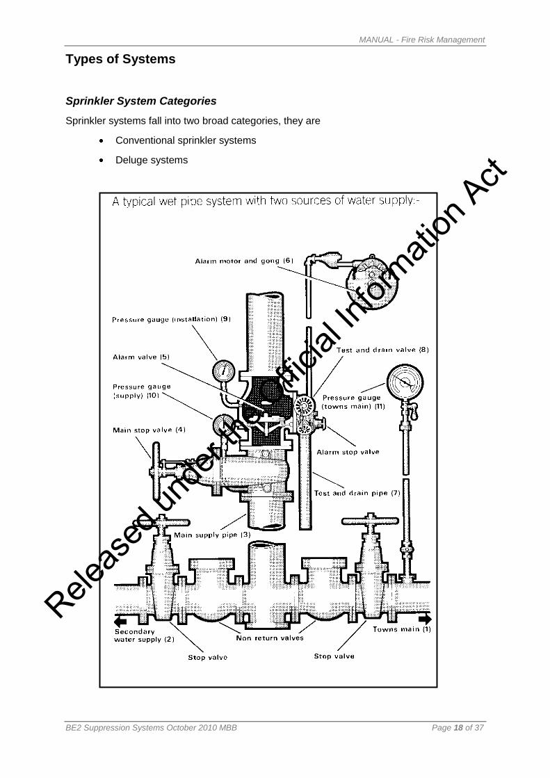
Types of Systems
Sprinkler System Categories
Sprinkler systems fall into two broad categories, they are
Conventional sprinkler systems
Deluge systems
Releas
ed un
der th
e Offic
ial In
formati
on A
ct
Page 19
MANUAL - Fire Risk Management
BE2 Suppression Systems October 2010 MBB Page 19 of 37
Conventional Systems
Conventional Sprinkler Systems
These systems include:
Wet pipe system
Alternate wet dry system
Wet pipe or alternate wet and dry pipe system incorporating tail end dry pipe
system
Wet pipe systems incorporating tail end alternate system
Dry Pipe system
Pre-action system
Anti-freeze system
Tail end anti-freeze system
Wet pipe system
Wet pipe systems are used whenever ambient temperatures remain at 4 o
C or above unless
otherwise permitted by the Standard. Sprinklers may be installed either in the upright or
pendent position.
Wet pipe system design and coverage
This system is designed so that the total floor area protected, excluding concealed spaces
controlled by one set of control valves, does not exceed 11,000 m2
Alternate wet and dry pipe system
During winter months this type of system is drained of water above the composite or alarm
(dry pipe) valve. The drained system is charged with gas under pressure. Water under
pressure is still present below the composite valve
Composite valve
Used on alternate wet and dry systems comprising an alarm (wet pipe) valve and an alarm
(dry pipe) valve.
Installation of Sprinklers
Sprinklers are normally installed above the range pipes unless the sprinklers are of an
approved dry pendent pattern type or if the area is not subject to freezing.
Releas
ed un
der th
e Offic
ial In
formati
on A
ct
Page 20
MANUAL - Fire Risk Management
BE2 Suppression Systems October 2010 MBB Page 20 of 37
Dry Pipe System
This type of system is normally only allowed in buildings where the temperature conditions
are artificially maintained close to or below freezing such as in cold or cool stores, fur vaults
and the like or where the temperature is maintained above 70o
C as in drying ovens.
Special conditions
The pipe work must be installed and arranged with adequate slope to allow for drainage.
Tail end alternate wet and dry pipe system
These systems are similar to dry pipe and alternate wet and dry pipe systems except they
are of comparatively small extent and form extensions to standard sprinkler installations.
Pre-Action System
This system incorporates two sets of pipe work:
Conventional pipe work with closed sprinkler heads charged with low pressure gas
(discharge sprinklers)
Small diameter pipe work fitted with closed sprinkler heads charged with gas (detection
sprinklers) designed for use in areas where accidental discharge of water due to mechanical
damage to sprinkler heads or pipe work is both unusually high and unacceptable.
Operation of Pre-Action system
Before this system will discharge water, both sets of sprinklers must have operated
Detection Sprinklers Temperature rating
The detection sprinklers on a pre action system may have a temperature rating of only 15o
C.
Anti-freeze system
This is a conventional wet pipe system in which the entire installation is charged with an anti-
freeze solution and connected to one or more water supplies.
Tail end anti-freeze system
These are portions of an installation that are arranged to protect a low temperature area by
means of an anti-freeze solution but as an extension of the conventional wet pipe system.
Releas
ed un
der th
e Offic
ial In
formati
on A
ct
Page 21
MANUAL - Fire Risk Management
BE2 Suppression Systems October 2010 MBB Page 21 of 37
Alternate system
Diagram showing an alternate system with accelerator.
Note: Due to the delayed response when the system is dry, an accelerator or exhauster may
be fitted to aid in the removal of the air from the system.
Releas
ed un
der th
e Offic
ial In
formati
on A
ct
Page 22
MANUAL - Fire Risk Management
BE2 Suppression Systems October 2010 MBB Page 22 of 37
Deluge Systems
Deluge Systems
Deluge systems normally comprise open sprinklers that are either:
Manually operated
Controlled by an automatic sensing device
Purpose
Deluge systems are designed for protection of special risks by suppressants or cooling to
permit controlled burning or cooling to prevent heat damage.
Releas
ed un
der th
e Offic
ial In
formati
on A
ct
Page 23
MANUAL - Fire Risk Management
BE2 Suppression Systems October 2010 MBB Page 23 of 37
Deluge Sprayers
Deluge systems are normally designed for extra high hazard areas and usually incorporate
either
Medium velocity sprayers
High velocity sprayers
Deluge Spray Heads
The diagram below shows two examples of the heads that may be incorporated into a deluge
system.
(1) Automatic Control Head. (2) An Open Sprayer
Releas
ed un
der th
e Offic
ial In
formati
on A
ct
Page 24
MANUAL - Fire Risk Management
BE2 Suppression Systems October 2010 MBB Page 24 of 37
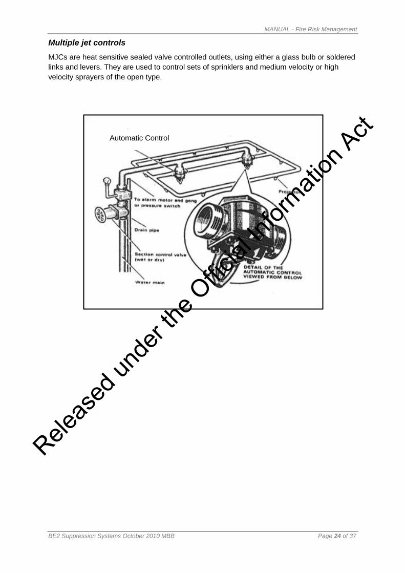
Multiple jet controls
MJCs are heat sensitive sealed valve controlled outlets, using either a glass bulb or soldered
links and levers. They are used to control sets of sprinklers and medium velocity or high
velocity sprayers of the open type.
Automatic Control
Releas
ed un
der th
e Offic
ial In
formati
on A
ct
Page 25
MANUAL - Fire Risk Management
BE2 Suppression Systems October 2010 MBB Page 25 of 37
Main Components of Wet Systems
Key components
Fire fighters must be able to identify the following key components of an automatic fire
sprinkler system:
Sprinkler Room or House
� Main Stop Valve
� Alarm Gong Stop Valve
� Test and Drain Valve
� Fire Brigade Control Valve
Brigade Inlet Connection
Installation Pressure Gauge
Towns Main Pressure Gauge
Alarm Valve Assembly
Alarm Gong
Booster Pump Controls
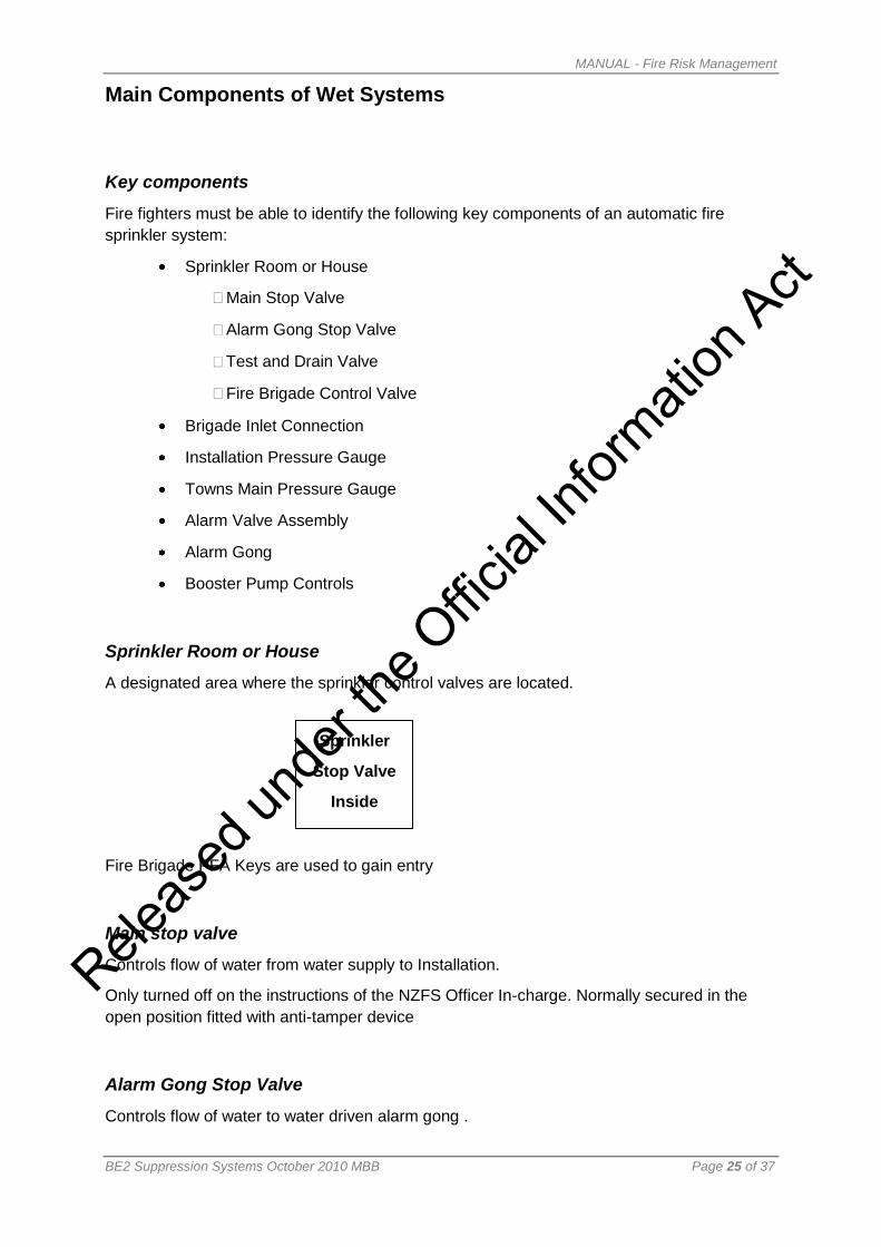
Sprinkler Room or House
A designated area where the sprinkler control valves are located.
Fire Brigade PFA Keys are used to gain entry
Main stop valve
Controls flow of water from water supply to Installation.
Only turned off on the instructions of the NZFS Officer In-charge. Normally secured in the
open position fitted with anti-tamper device
Alarm Gong Stop Valve
Controls flow of water to water driven alarm gong .
Sprinkler
Stop Valve
Inside
Releas
ed un
der th
e Offic
ial In
formati
on A
ct
Page 26
MANUAL - Fire Risk Management
BE2 Suppression Systems October 2010 MBB Page 26 of 37
Test and Drain Valve
Used by the Fire Brigade to drain down the sprinkler system
Brigade Inlet Connection
Male Instantaneous coupling for Fire Brigade to connect to supplement installation supply
and pressure.
Triangular key normally opens cabinet box
Wire glazed panel provided to enable forced entry if necessary
Brigade Booster Control Wheel
Hand wheel on some systems that must be opened prior to Fire brigade boosting the water
supply and pressure.
Towns Main Pressure Gauge
Fitted to each reticulated water supply to indicate mains pressure
Alarm Valve Assembly
The alarm valve assembly is located just above the Main Stop Valve on the installation side
of the system. It contains the clack valve assembly.
Alarm Gong
Usually located close to the Sprinkler House on an exterior wall.
A water driven (Pelton Wheel Motor) alarm gong
Water may be discharging from a pipe on the alarm gong when it is sounding
Fire Brigade
Sprinkler
Inlet
Releas
ed un
der th
e Offic
ial In
formati
on A
ct
Page 27
MANUAL - Fire Risk Management
BE2 Suppression Systems October 2010 MBB Page 27 of 37
Booster Pump Controls
Some sprinkler systems will be fitted with electric or diesel stationary motors that drive
pumps to increase the water supply to the system
Instructions are provided on SHUT DOWN and START UP procedures.
Read the instructions provided before acting
Sprinklers
Sprinklers for use on automatic fire sprinkler installations come in a variety of styles and
patterns
Various Sprinkler Heads
Releas
ed un
der th
e Offic
ial In
formati
on A
ct
Page 28
MANUAL - Fire Risk Management
BE2 Suppression Systems October 2010 MBB Page 28 of 37
Glass Bulb Sprinkler Head Construction
The following shows the components of a glass bulb sprinkler head
Heat causes the liquid in the bulb to expand. The bulb shatters as the liquid tries to compress
thus releasing the water onto the deflector
Fusible Link Sprinkler Head Construction
The following shows the components of a fusible link sprinkler head
Heat causes the fusible link to melt thus releasing the stopper device thus releasing the
water onto the deflector
Quartzoid Bulb Type Sprinkler Head
Releas
ed un
der th
e Offic
ial In
formati
on A
ct
Page 29
MANUAL - Fire Risk Management
BE2 Suppression Systems October 2010 MBB Page 29 of 37
Sprinkler Head Coding
The colour code for sprinkler heads is shown below. The colours distinguish the different
temperature ratings.
Fusible Link Sprinklers Glass Bulb Types
Temperature
Rating °C
Colour of yoke arms Temperature
Rating °C
Colour of bulbs
57-77 Natural (uncoloured) 57 Orange
80-107 White 68 Red
121-141 Blue 79 Yellow
163-191 Red 93 Green
204-246 Green 141 Blue
260-302 Orange 182 Mauve
320-343 Black 227-260 Black
Other Types of sprinklers
Sprinklers are manufactured in a variety of forms depending on the installation type and area
of operation
Recessed Sprinkler Head
Releas
ed un
der th
e Offic
ial In
formati
on A
ct
Page 30
MANUAL - Fire Risk Management
BE2 Suppression Systems October 2010 MBB Page 30 of 37
Sprayers
Sprayers usually refer to sprinkler heads for use on medium and high density discharge
deluge systems
Medium and High Velocity Sprayers
Releas
ed un
der th
e Offic
ial In
formati
on A
ct
Page 31
MANUAL - Fire Risk Management
BE2 Suppression Systems October 2010 MBB Page 31 of 37
Sprinkler System Water Supplies - Types of Water Supply
Introduction
A sprinkler system depends upon its water supply and based upon a building’s fire hazard
classification will determine the number of water supplies the sprinkler system must have.
Water supplies are generally classified as primary or secondary. The water supply is defined
by its flow in pressure
Primary Supply
A primary supply shall be one of the following:
(a) A town main, boosted town main, or supplemented town main provided
that any pump is driven by a diesel engine.
(b) A diesel engine driven pump, taking water from an approved source other
than a town main.
(c) An elevated tank
(d) A pressure tank (extra light hazard only)
Secondary Supply
A secondary supply shall be one of the following:
(a) A town’s main, boosted town main, or supplemented town main where any
pump is either diesel engine or electric motor driven
(b) A diesel engine or electric driven pump, taking water from an approved
source other than a town main
(c) An elevated tank
(d) A pressure tank (extra light hazard only)
Protection of Towns Mains
Back flow prevention is required to protect towns mains from cross contamination from the
installation and secondary supplies or private fire mains.
Releas
ed un
der th
e Offic
ial In
formati
on A
ct
Page 32
MANUAL - Fire Risk Management
BE2 Suppression Systems October 2010 MBB Page 32 of 37
Classes of Water Supply
Classification
Water supplies are classified as follows:
Class A
Class B2
Class C 2
Class C1
Class A - Dual superior supply
Two approved supplies, both of which shall be carried independently to a combined main
within each control valve enclosure, at least one of which shall be a primary supply, but only
one of which may be dependant on a town's main.
Class B2 - Private site fire main
A private reticulation system which complies with the Standard and is reserved solely for fire
purposes, being charged with water and normally pressurised, comprising at least one ring
and supplied by two approved water supplies, at least one of which shall be a primary
supply, but only one of which may be dependant on a town's main.
Two connections shall be carried independently to a combine main within each valve
enclosure.
Isolation valves shall be provided at each connect with the fire main and so as to ensure
there are at least two isolation valves between any two connections.
Class C Single supply
One approved primary supply
Tank capacity
The following table (from NZS 4541)shows the minimum storage tank capacity required for
hazard classifications
Hazard Classification Primary Supply Secondary Supply
Extra Light 60 Min x Design Flow 40 min x Design Flow
Ordinary 60 min x Design Flow 40 min x Design Flow
Extra High See Table 6.1 in Standard See Table 6.1 in Standard
Releas
ed un
der th
e Offic
ial In
formati
on A
ct
Page 33
MANUAL - Fire Risk Management
BE2 Suppression Systems October 2010 MBB Page 33 of 37
Design Criteria
Each Hazard Classification sets down the water supply required based on area of operation
and design density requirements for each specific area of operation
Early Suppression Fast Response: ESFR
Storage occupancies present a number of particular problems for sprinkler protection. There
are several reasons why this should be so:
the vertical surfaces and natural flues presented by stored goods promote rapid fire spread
the sprinkler heads may be a long way above the fire and may take some time to operate
there is a good chance that the fire may be shielded from the spray
by the time water gets to the fire the heat release rate may be so great that the spray is
ineffective
Installing in-rack sprinkler systems may solve these problems. These are highly effective but
are seen as expensive in some instances and prone to mechanical damage from forklift
trucks for example.
The problem was solved for certain types of storage by the development of the Early
Suppression Fast Response sprinkler. The sprinkler relies on large diameter pipe work and a
specially designed orifice that delivers a far greater density of water than a conventional
sprinkler head. This density was determined by actual measurements on large storages. In
addition the design of the deflector plate promotes the production of large drops preferentially
which penetrate the plume and wet the fire at source. These sprinklers aim to suppress the
fire, not just to control it, with the action of only 3 or 4 heads. They are of course fast
response so that the water is delivered to the fire as rapidly as possible. The storage
conditions suited to the use of these sprinklers are quite stringently defined.
ESFR Heads
Releas
ed un
der th
e Offic
ial In
formati
on A
ct
Page 34
MANUAL - Fire Risk Management
BE2 Suppression Systems October 2010 MBB Page 34 of 37
Water Mist
There is increasing interest in certain applications in the use of water mists or fog systems for
extinguishing purposes. The water mist divides the spray up into very fine droplets by use of
a high-pressure gas. Small droplets have a much higher surface area than large droplets,
and so the droplets can evaporate more quickly and absorb heat more effectively. This
suggests that less water could be used in tackling the fire, as less is likely to be wasted.
Such systems are used in ships and in applications such as tunnels where access for
conventional firefighting is restricted.
Entrainment of water droplets
Large-scale experimental work on the suppression of fires in oil and gas wells has made use
of fine water mists coupled with the natural tendency of the flame to entrain air. By
introducing the mist droplets around the base of the flame they are naturally drawn into the
flame by the entrainment process. Once in the flame the droplets are rapidly vaporised and
heated to flame temperatures, removing heat in the process. Because of the way in which
the droplets are drawn into the flame, the effectiveness of the cooling becomes much more
efficient as so little is lost to the surroundings. The quantities of water used in such
applications some much closer to the theoretical values calculated earlier.
Releas
ed un
der th
e Offic
ial In
formati
on A
ct
Page 35
MANUAL - Fire Risk Management
BE2 Suppression Systems October 2010 MBB Page 35 of 37
Fire Brigade Systems - Fire Hydrant Systems for Buildings
Fire Hydrant
A building fire hydrant is provided for the Fire Service to reticulate fire fighting water.
Water is drained from the in-ground public water mains and pumped via the appliance into
the system.
Building Pumps
Where Fire Service appliances are not capable of producing the pressure required at the
outlet, building pumps are provided.
Pre Inlet Pressure
The pressure a Fire Service appliance can currently deliver to the inlet of the hydrant system
is 1050 kpa. This is the pressure limitation of the single lugged instantaneous coupling.
Outlet Pressure
600 – 1200 kpa
Flow Rate
7.3 l/s per outlet.
Standard
NZS: 4510
Releas
ed un
der th
e Offic
ial In
formati
on A
ct
Page 36
MANUAL - Fire Risk Management
BE2 Suppression Systems October 2010 MBB Page 36 of 37
Types of Systems
Dry System
System contains no water.
No longer allowed under standard.
Wet System
System filled with water and ancillary pumps as necessary to deliver required flows at outlets
from mains. Does not require Fire Service appliance.
Charged System
System filled with water by small mains connection. Requires Fire Service appliance to
deliver required flows.
Number of Outlets Required
Require an outlet within the building capable of reaching extremities of the building within a
50m arc.
Measurement of Arc
Taken from outlet on that floor if outlet within a protected lobby, or taken from the floor below,
allowing for extra distance required to ascend stairs.
Protected Lobby
An enclosed part of the floor, having an area of 6m2
or more.
• Must be directly accessible from stair
• Minimum fire resistance rating of 60/60/60
Fire Service Inlet
Within 18m of accessible position for fire appliance.
Releas
ed un
der th
e Offic
ial In
formati
on A
ct
Page 37
MANUAL - Fire Risk Management
BE2 Suppression Systems October 2010 MBB Page 37 of 37
information
A waterproof book must be provided in the inlet housing with a diagram showing all:
valves
outlets
pressure control devices
pumps
settings of all pressure reducing valves
Pumps
Manually started (after charging with water if necessary)
Manually stopped
Hydrant Requirement NZ 4510
Hose Streams Building Ave floor area
(Max) M2
Outlets per floor Max water flow l/s
2 Single storey 4900 1 14.6
4 Multiple storey 4900 1 29.3
8 9800 2 58.7
10 14700 3 73.3
12 19600 4 88
Note: Pre-1998 flows and outputs will vary .
Releas
ed un
der th
e Offic
ial In
formati
on A
ct