Schimmel: Delay-Line Receiving Arrays cases 1, 2, 3, and 4, while in the nonfluctuating target case F varies more widely. This shows up in the cumu- lative probability curves as a variation in optimum F with R/R1 in this target case. As mentioned in the foregoing, a simple relationship was found empirically for the optimum first threshold. Because the optimum threshold is essentially indepen- dent of signal-to-noise ratio, this relationship is particu- larly useful in computing cumulative detection prob- abilities, where a single preset threshold may be used for all ranges. In all the cases it was found that, for near-optimum values of the design parameters (F and b1), the blip/scan ratio varies slowly with these parameters. That is, the curves of blip/scan ratio vs. F or bi are relatively flat near the optimum. This is illustrated in Fig. 16 for a case 1 target. ACKNOWLEDGMENTS The authors are indebted to J. D. Mallett for assis- tance in formulating the problem and for many helpful discussions and to I. Selin for several constructive suggestions. REFERENCES [1] A. Wald, Sequential Analysis. New York: Wiley, 1947. [2] M. B. Marcus and P. Swerling, "Sequential detection in radar with multiple resolution elements," IRE Trans. on Information Theory, vol. IT-8, pp. 237-245, April 1962. [31 C. W. Helstrom. "A range-sampled sequential detection system," IRE Trans. on Information Theory, vol. IT-8, pp. 43-47, January 1962. [4] I. S. Reed and I. Selin, "A sequential test for the presence of a signal in one of k possible positions," IEEE Trans. on Informa- tion Theory (Correspondence), vol. IT-9, pp. 286-288, October 1963. [5] G. Preston, "The search and detection efficiency of surveillance and communication devices using sequential probability ratio analysis," Proc. Sym. on Decision Theory and Appl. to Electronic Equipment Dev., vol. 1, pp. 100-117, May 1960. [6] H. M. Finn, "A new approach to sequential detection in phased array radars," 1963 National Winter Convention on Military Electronics. [7] J. I. Marcum and P. Swerling, "Studies of target detection by pulsed radar," IRE Trans. on Information Theory, vol. IT-6, pp. 59-308, April 1960. [8] J. D. Mallett and L. E. Brennan, "Cumulative probability of detection for targets approaching a uniformly scanning search radar," Proc. IEEE, vol. 51, pp. 596-601, April 1963. [9] L. E. Brennan, and I. S. Reed, "An iterative method of com- puting the Q-function," The RAND Corp., Santa Monica, Calif., P-2949, July 1964. [10] L. E. Brennan and F. S. Hill, Jr., "A two-step sequential pro- cedure for improving the cumulative probability of detection in radars," The RAND Corp., Santa Monica, Calif., RM-4338-PR, October 1964. Activated Delay-Line Receiving Arrays HOWARD SCHIMMEL, MEMBER, IEEE Abstract-A discussion of the theory and applications of activated delay lines is presented. The term "activated delay line" is derived from the fact that the equivalent circuit of a ceramic electroacoustic receiving transducer is a capacitor in series with a voltage generator and for this reason may be inserted directly into an LC delay-line receiving array matrix. Equations are derived which give array gain as a function of the number of serially added array elements. Very large arrays are theoretically possible. Since activated delay lines are composed entirely of passive components, they are very rugged, reliable, and relatively inexpensive. I NTRODUCTION ACOUSTIC RECEIVING arrays have been em- ployed in the solution of sonar problems for a number of years [1]. As the requirements on system performance have increased, the complexity of receiving arrays has increased. One type using the acti- vated delay-line approach has proved to be particularly Manuscript received January 25, 1965; revised February 22, 1965. The work reported in this paper was supported by the Office of Naval Research under Contract Nonr-266(66). Reproduction in whole or in part is permitted for any purpose of the United States Gov't. This paper is Contribution No. 211 of the Hudson Labs. of Columbia University, New York, N. Y. The author is with the Hudson Labs., Columbia University, Dobbs Ferry, N. Y. advantageous. Although the exact origin of the acti- vated delay line is somewhat obscure, it appears that the concept originated during discussions attended by H. Sonnemann, formerly of Hudson Laboratories, H. E. Nash of the U. S. Navy Underwater Sound Laboratories, and others. Since they are formed entirely of passive components, activated delay lines do not suffer from the disadvan- tages usually associated with preamplifiers, etc., and yet have sufficient power gain to drive long lengths of cable. The idea is quite simple. The term "activated delay line" is derived from the fact that the equivalent circuit of a ceramic electroacoustic receiving transducer is a capacitor in series with a voltage generator and for this reason may serve as both the capacitive element and the transducer of acoustic energy, as shown in Fig. 1 where Zo is the characteristic impedance of the delay line, L the delay-line inductance, Ce the transducer electrical capacitance, and Ek the open circuit voltage of the kth transducer. The individual transducers (hydrophones) are all identical and are spatially distributed. The electrical delays are equal to the acoustic delays associated with 1965 287
Transcript
Schimmel: Delay-Line Receiving Arrays
cases 1, 2, 3, and 4, while in the nonfluctuating targetcase F varies more widely. This shows up in the cumu-lative probability curves as a variation in optimum Fwith R/R1 in this target case.
As mentioned in the foregoing, a simple relationshipwas found empirically for the optimum first threshold.Because the optimum threshold is essentially indepen-dent of signal-to-noise ratio, this relationship is particu-larly useful in computing cumulative detection prob-abilities, where a single preset threshold may be used forall ranges.
In all the cases it was found that, for near-optimumvalues of the design parameters (F and b1), the blip/scanratio varies slowly with these parameters. That is, thecurves of blip/scan ratio vs. F or bi are relatively flatnear the optimum. This is illustrated in Fig. 16 for a
case 1 target.
ACKNOWLEDGMENTSThe authors are indebted to J. D. Mallett for assis-
tance in formulating the problem and for many helpfuldiscussions and to I. Selin for several constructivesuggestions.
REFERENCES[1] A. Wald, Sequential Analysis. New York: Wiley, 1947.[2] M. B. Marcus and P. Swerling, "Sequential detection in radar
with multiple resolution elements," IRE Trans. on InformationTheory, vol. IT-8, pp. 237-245, April 1962.
[31 C. W. Helstrom. "A range-sampled sequential detection system,"IRE Trans. on Information Theory, vol. IT-8, pp. 43-47,January 1962.
[4] I. S. Reed and I. Selin, "A sequential test for the presence of asignal in one of k possible positions," IEEE Trans. on Informa-tion Theory (Correspondence), vol. IT-9, pp. 286-288, October1963.
[5] G. Preston, "The search and detection efficiency of surveillanceand communication devices using sequential probability ratioanalysis," Proc. Sym. on Decision Theory and Appl. to ElectronicEquipment Dev., vol. 1, pp. 100-117, May 1960.
[6] H. M. Finn, "A new approach to sequential detection in phasedarray radars," 1963 National Winter Convention on MilitaryElectronics.
[7] J. I. Marcum and P. Swerling, "Studies of target detection bypulsed radar," IRE Trans. on Information Theory, vol. IT-6, pp.59-308, April 1960.
[8] J. D. Mallett and L. E. Brennan, "Cumulative probability ofdetection for targets approaching a uniformly scanning searchradar," Proc. IEEE, vol. 51, pp. 596-601, April 1963.
[9] L. E. Brennan, and I. S. Reed, "An iterative method of com-puting the Q-function," The RAND Corp., Santa Monica,Calif., P-2949, July 1964.
[10] L. E. Brennan and F. S. Hill, Jr., "A two-step sequential pro-cedure for improving the cumulative probability of detection inradars," The RAND Corp., Santa Monica, Calif., RM-4338-PR,October 1964.
Activated Delay-Line Receiving Arrays
HOWARD SCHIMMEL, MEMBER, IEEE
Abstract-A discussion of the theory and applications of activateddelay lines is presented. The term "activated delay line" is derivedfrom the fact that the equivalent circuit of a ceramic electroacousticreceiving transducer is a capacitor in series with a voltage generatorand for this reason may be inserted directly into an LC delay-linereceiving array matrix. Equations are derived which give array gainas a function of the number of serially added array elements. Verylarge arrays are theoretically possible. Since activated delay lines arecomposed entirely of passive components, they are very rugged,reliable, and relatively inexpensive.
I NTRODUCTION
ACOUSTIC RECEIVING arrays have been em-
ployed in the solution of sonar problems for a
number of years [1]. As the requirements on
system performance have increased, the complexity ofreceiving arrays has increased. One type using the acti-vated delay-line approach has proved to be particularly
Manuscript received January 25, 1965; revised February 22,1965. The work reported in this paper was supported by the Office ofNaval Research under Contract Nonr-266(66). Reproduction inwhole or in part is permitted for any purpose of the United StatesGov't. This paper is Contribution No. 211 of the Hudson Labs. ofColumbia University, New York, N. Y.
The author is with the Hudson Labs., Columbia University,Dobbs Ferry, N. Y.
advantageous. Although the exact origin of the acti-vated delay line is somewhat obscure, it appears that theconcept originated during discussions attended byH. Sonnemann, formerly of Hudson Laboratories,H. E. Nash of the U. S. Navy Underwater SoundLaboratories, and others.
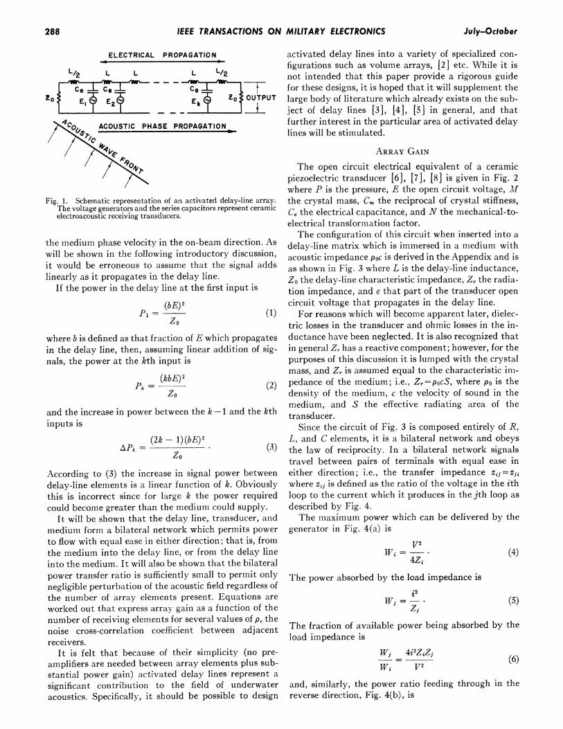
Since they are formed entirely of passive components,activated delay lines do not suffer from the disadvan-tages usually associated with preamplifiers, etc., and yethave sufficient power gain to drive long lengths of cable.The idea is quite simple. The term "activated delayline" is derived from the fact that the equivalent circuitof a ceramic electroacoustic receiving transducer is a
capacitor in series with a voltage generator and for thisreason may serve as both the capacitive element and thetransducer of acoustic energy, as shown in Fig. 1 whereZo is the characteristic impedance of the delay line, Lthe delay-line inductance, Ce the transducer electricalcapacitance, and Ek the open circuit voltage of the kthtransducer.The individual transducers (hydrophones) are all
identical and are spatially distributed. The electricaldelays are equal to the acoustic delays associated with
1965 287
IEEE TRANSACTIONS ON MILITARY ELECTRONICS
ELECTRICAL PROPAGATION
L/2 L L L L/2
Ce C*8
r-L2 - -
4,' ACOUSTIC PHASE PROPAGATION
activated delay lines into a variety of specialized con-figurations such as volume arrays, [2] etc. While it isnot intended that this paper provide a rigorous guidefor these designs, it is hoped that it will supplement thelarge body of literature which already exists on the sub-ject of delay lines [3], [4], [5] in general, and thatfurther interest in the particular area of activated delaylines will be stimulated.
Fig. 1. Schematic representation of an activated delay-line array.The voltage generators and the series capacitors represent ceramicelectroacoustic receiving transducers.
the medium phase velocity in the on-beam direction. Aswill be shown in the following introductory discussion,it would be erroneous to assume that the signal addslinearly as it propagates in the delay line.
If the power in the delay line at the first input is
P= (bE))zo
where b is defined as that fraction of E which propagatesin the delay line, then, assuming linear addition of sig-nals, the power at the kth input is
(kbE)2Pk = (2)zo
and the increase in power between the k -1 and the kthinputs is
AP0= (2k- 1)(b) (2zo
According to (3) the increase in signal power betweendelay-line elements is a linear function of k. Obviouslythis is incorrect since for large k the power requiredcould become greater than the medium could supply.
It will be shown that the delay line, transducer, andmedium form a bilateral network which permits powerto flow with equal ease in either direction; that is, fromthe medium into the delay line, or from the delay lineinto the medium. It will also be shown that the bilateralpower transfer ratio is sufficiently small to permit onlynegligible perturbation of the acoustic field regardless ofthe number of array elements present. Equations areworked out that express array gain as a function of thenumber of receiving elements for several values of p, thenoise cross-correlation coefficient between adjacentreceivers.
It is felt that because of their simplicity (no pre-amplifiers are needed between array elements plus sub-stantial power gain) activated delay lines represent asignificant contribution to the field of underwateracoustics. Specifically, it should be possible to design
ARRAY GAIN
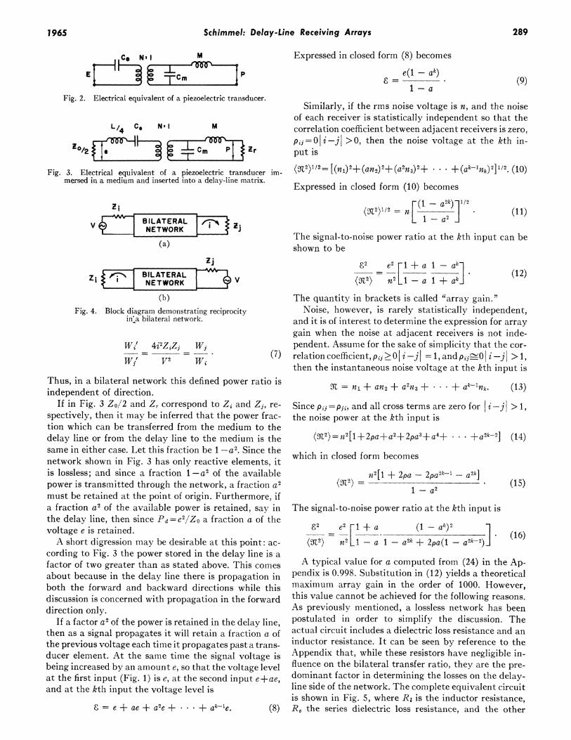
The open circuit electrical equivalent of a ceramicpiezoelectric transducer [6], [7], [8] is given in Fig. 2where P is the pressure, E the open circuit voltage, Mthe crystal mass, Cm the reciprocal of crystal stiffness,Ce the electrical capacitance, and N the mechanical-to-electrical transformation factor.The configuration of this circuit when inserted into a
delay-line matrix which is immersed in a medium withacoustic impedance poc is derived in the Appendix and isas shown in Fig. 3 where L is the delay-line inductance,Z0 the delay-line characteristic impedance, Zr the radia-tion impedance, and e that part of the transducer opencircuit voltage that propagates in the delay line.
For reasons which will become apparent later, dielec-tric losses in the transducer and ohmic losses in the in-ductance have been neglected. It is also recognized thatin general Zr has a reactive component; however, for thepurposes of this discussion it is lumped with the crystalmass, and Zr is assumed equal to the characteristic im-pedance of the medium; i.e., Zr=poCS, where PO is thedensity of the medium, c the velocity of sound in themedium, and S the effective radiating area of thetransducer.
Since the circuit of Fig. 3 is composed entirely of R,L, and C elements, it is a bilateral network and obeysthe law of reciprocity. In a bilateral network signalstravel between pairs of terminals with equal ease ineither direction; i.e., the transfer impedance zij=zjiwhere zij is defined as the ratio of the voltage in the ithloop to the current which it produces in the jth loop asdescribed by Fig. 4.The maximum power which can be delivered by the
generator in Fig. 4(a) is
V2Wi =
4ZjThe power absorbed by the load impedance is
Wj = - .
Zi
(4)
(5)
The fraction of available power being absorbed by theload impedance is
Wi 4i'ZiZjWi V2
(6)
and, similarly, the power ratio feeding through in thereverse direction, Fig. 4(b), is
_ . July-October288
Schimmel: Delay-Line Receiving Arrays
Co Ns I M
Fig. 2. Electrical equivalent of a piezoelectric transducer.
L/4 CO Ng I M
Z°/2 c m Zr
Fig. 3. Electrical equivalent of a piezoelectric transducer im-mersed in a medium and inserted into a delay-line matrix.
Expressed in closed form (8) becomes
e(1 - ak)1-a
(9)
Similarly, if the rms noise voltage is n, and the noiseof each receiver is statistically independent so that thecorrelation coefficient between adjacent receivers is zero,pjj=0i-jI >0, then the noise voltage at the kth in-put is
Thus, in a bilateral network this defined power ratio isindependent of direction.
If in Fig. 3 Zo/2 and Zr correspond to ZA and Zj, re-spectively, then it may be inferred that the power frac-tion which can be transferred from the medium to thedelay line or from the delay line to the medium is thesame in either case. Let this fraction be 1 -a2. Since thenetwork shown in Fig. 3 has only reactive elements, itis lossless; and since a fraction 1 -a2 of the availablepower is transmitted through the network, a fraction a2must be retained at the point of origin. Furthermore, ifa fraction a2 of the available power is retained, say inthe delay line, then since Pd=e2/Zo a fraction a of thevoltage e is retained.A short digression may be desirable at this point: ac-
cording to Fig. 3 the power stored in the delay line is afactor of two greater than as stated above. This comesabout because in the delay line there is propagation inboth the forward and backward directions while thisdiscussion is concerned with propagation in the forwarddirection only.
If a factor a2 of the power is retained in the delay line,then as a signal propagates it will retain a fraction a ofthe previous voltage each time it propagates past a trans-ducer element. At the same time the signal voltage isbeing increased by an amount e, so that the voltage levelat the first input (Fig. 1) is e, at the second input e+ae,and at the kth input the voltage level is
E = e + ae + a2e + * - * + ak- e. (8)
=V l 2 (t - a2k) 1/2=
)12n 1a(11)
The signal-to-noise power ratio at the kth input can beshown to be
82 e2 -1 + a 1 -ak](X2) n2 _1 -a + ak_
(12)
The quantity in brackets is called "array gain."Noise, however, is rarely statistically independent,
and it is of interest to determine the expression for arraygain when the noise at adjacent receivers is not inde-pendent. Assume for the sake of simplicity that the cor-relation coefficient, Pij ! O i-j = 1, and pij-OI i -j > 1,then the instantaneous noise voltage at the kth input is
s = ni + an2 + a2n3 + * * . + ak-Ink. (13)
Since pij = pj, and all cross terms are zero for |i -j > 1,the noise power at the kth input is
(K2)=n2[1+2pa+a2+2pa3+a4+ * * +a2k-2]
which in closed form becomes
(M2) =n2[1 + 2pa - 2pa2k1 - a2k]
1 - a2
The signal-to-noise power ratio at the kth input is
82 e2 [l+a a I(1-ak)2
OZ2) n2 1-t-a t1- a2k+ 2pa(1-a2k-2)
(14)
(15)
(16)
A typical value for a computed from (24) in the Ap-pendix is 0.998. Substitution in (12) yields a theoreticalmaximum array gain in the order of 1000. However,this value cannot be achieved for the following reasons.As previously mentioned, a lossless network has beenpostulated in order to simplify the discussion. Theactual circuit includes a dielectric loss resistance and aninductor resistance. It can be seen by reference to theAppendix that, while these resistors have negligible in-fluence on the bilateral transfer ratio, they are the pre-dominant factor in determining the losses on the delay-line side of the network. The complete equivalent circuitis shown in Fig. 5, where R1 is the inductor resistance,R, the series dielectric loss resistance, and the other
2891965
IEEE TRANSACTIONS ON MILITARY ELECTRONICS
L/4 RL/4 RC Cg N s I M
Z o/>Irj~j7JTcZr
Fig. 5. Electrical equivalent, including loss resistances, of a piezo-electric transducer immersed in a medium and inserted into a
delay-line matrix.
200
.99160 /
z 120
a .98
~t80-
0"= .97
20
0
0 2
ARRAY ELEMENTS, K x 102
Fig. 6. Plot of array gain versus the number of array elements withthe voltage retention per delay-line section, a, as parameter.
120-
a=.98 p==.8 p=
CD~ ~ ~ RA a=EMENTS,Kx 10
Fig. 7. Plot of array gain versus the number of array elements withthe voltage retention per delay-line section a = 0.98, and thenoise cross-correlation coefficient, p, as parameter.
circuit elements are as defined earlier.It is shown in the Appendix that the dissipation con-
stant R,/X, is usually in the order of one per cent andthe quality factor Xe/Re in the order of 20, and thatthese resistances combine to reduce the voltage re-
tention per delay-line section from the order of 0.998 tothe order of 0.98. Thus the predominant factor in deter-mining theoretical array gain is ohmic loss on the delay-
line side of the network rather than the bilateral powertransfer ratio. Conversely, the bilateral power transferratio is small so there is negligible perturbation of theacoustic field regardless of the number of elementspresent.A plot is shown in Fig. 6 of array gain versus number
of array elements (12) for values of a between 0.93 and0.99. At first the array gain is equal to the numberof array elements and then gradually approaches anasymptotic limit. In Fig. 7 a plot is shown of (16) for aequal to 0.98 and p=0, 0.05, and 0.10. It may be seenfrom the figure that a small amount of correlated noisedoes not seriously reduce the array gain.
POSSIBLE APPLICATIONS
Because of their extreme simplicity, activated delaylines lend themselves to a variety of situations whereother solutions, for one reason or another, are not en-tirely satisfactory. This is particularly true where cost,reliability, and ease of handling are primary considera-tions.
In general, three types of arrays may be constructed:
1) Volume arrays2) Line arrays3) Special purpose arrays.
For example, nonsteerable volume arrays with gainsin the order of 105 are possible provided the medium hassufficient coherence over distances in the order of 25wavelengths or more. That is to say 50 elements may bespaced 1/2 wavelength to form a cube 50 elements ona side1 as shown in Fig. 8.
It is not inconceivable that steerable volume arrayscould prove practical. These would entail the use ofvariable inductors and/or variable condensers.As may be seen by reference to Figs. 6 and 7, line ar-
rays with several hundred elements may be constructed,subject, of course, to the limitations imposed by themedium. As with volume arrays, line arrays could bemade steerable through the use of variable inductors.
Special purpose arrays may be constructed which, inaddition to being selective in the spatial sense, are alsofrequency selective. Consider the closed array shown inFig. 9. This array exhibits the properties of a combfilter. If the period of the fundamental frequency of thedesired class of signals is just equal to the delay timebetween transducers, then that frequency plus all itsharmonics will always be in phase with the signal in themedium. Thus a signal processing gain will result. Theprocessing gain is computed in the same way as for aline array, and gains in the order of a hundred or moreshould be typical. It should also be possible to tune thistype of array to a particular fundamental frequencythrough the use of variable inductors.
1 No limitations (except those imposed by the medium) exist onthe number of array elements or groups of array elements whichmay be added in parallel.
290 July-October
Schimmel: Delay-Line Receiving Arrays
kz t -
\ky
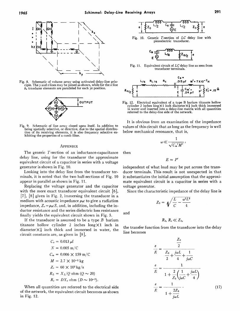
Fig. 8. Schematic of volume array using activated delay-line prin-ciple. The y and z lines may be joined as shown, while for the x linek, tranducer elements are paralleled for each yz position.
Fig. 9. Schematic of line array closed upon itself. In addition tobeing spatially selective, or directive, due to the spatial distribu-tion of its receiving elements, it is also frequency selective ex-hibiting the properties of a comb filter.
Fig. 10. Generic T-section of LC delay line withpiezoelectric transducer.
E Y
Fig. 11. Equivalent circuit of LC delay line as seen fromtransducer terminals.
L/4 Rl /4 Rc .013O f Ml= 7XIO-7H
°O/2jCM
l .-.15la
Fig. 12. Electrical equivalent of a type B barium titanate hollowcylinder 2 inches longX 1 inch diameterXl inch thick immersedin water and inserted into a delay-line matrix with all quantitiesreferred to the delay-line side of the network.
It is obvious from an examination of the impedancevalues of this circuit that as long as the frequency is wellbelow mechanical resonance, that is,
1
APPENDIX -\//CmIMIThe generic T-section of an inductance-capacitance
delay line, using for the transducer the approximateequivalent circuit of a capacitor in series with a voltagegenerator is shown in Fig. 10.
Looking into the delay line from the transducer ter-minals, it is noted that the two half-sections of Fig. 10appear in parallel as shown in Fig. 11.
Replacing the voltage generator and the capacitorwith the more exact transducer equivalent circuit [6],[7], [8] given in Fig. 2, immersing the transducer in amedium with acoustic impedance poc to give a radiationimpedance, Zr=POCS, and, in addition, including the in-ductor resistance and the series dielectric loss resistancefinally yields the equivalent circuit shown in Fig. 5.
If the transducer is assumed to be a type B bariumtitanate hollow cylinder 2 inches long X 1 inch indiameter X 1 inch thick and immersed in water, thecircuit constants are, as given in [8],
Ce = 0.013 ,fN = 0.005 m/CCm = 0.006 X 159 m/CM = 2.7 X 10⁻² kgZr = 60 X 102kg/sRL = XL/Q ohm (Q 20)Rc= DX, ohm (D -- 10-2).
When all quantities are referred to the electrical sideof the network, the equivalent circuit becomes as shownin Fig. 12.
then
E P'
independent of what load may be put across the trans-ducer terminals. This result is not unexpected in thatit substantiates the initial assumption that the approxi-mate equivalent circuit is a capacitor in series with avoltage generator.
Since the characteristic impedance of the delay line is
//L w2L2VC 4
and
Ri, Rc << ZO,
the transfer function from the transducer into the delayline becomes
zo
e 2
E Zo jwL 1
2 4 jcoCe 1
E 2 1 joLX
Zo jcC 4
e 1
E 2Zo1 +
jwL
(17)
2911965
IEEE TRANSACTIONS ON MILITARY ELECTRONICS
By taking the magnitude of the transfer functionthen substituting for Zo, it can be seen that
4Z02e 'V a2L2E 1 2Z2
wL
e 1
co,2L2
e
gel=('9)\ILC.E 2
The power imparted to the delay line due to the sopressure at a particular transducer is
2e2Wd = -- .
zo
L/2 Rl/2
0 e
RL /2 L/2
Rc
1ce ! }oI
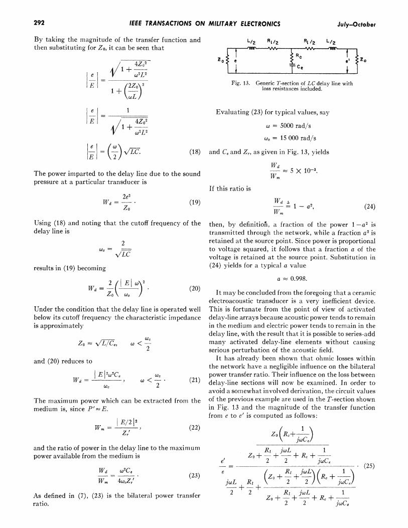
Fig. 13. Generic T-section of LC delay line withloss resistances included.
Evaluating (23) for typical values, say
w -5000 rad/s
c= 15 000 rad/s
(18) and Ce and Zr, as given in Fig. 13, yields
Wd_und 5 X 10-3.und Wm
If this ratio is
Wd A= 1-a2Wm?
Using (18) and noting that the cutoff frequency of thedelay line is
2C = \ILC
results in (19) becoming
Wd = 2 ({ El o') . (20)
Under the condition that the delay line is operated well
below its cutoff frequency the characteristic impedanceis approximately
Zo V\ILIC,,
and (20) reduces to
IEWd=-
cc
c2<2
CeCI <K-
2
The maximum power which can be extracted from themedium is, since P'zE.
Wm = E/2 (22)Zr'
and the ratio of power in the delay line to the maximumpower available from the medium is
Wd w2Ce
W.m 4ocZr'(23)
As defined in (7), (23) is the bilateral power transferratio.
then, by definition, a fraction of the power 1 -a2 istransmitted through the network, while a fraction a2 isretained at the source point. Since power is proportionalto voltage squared, it follows that a fraction a of thevoltage is retained at the source point. Substitution in(24) yields for a typical a value
a 0.998.
It may be concluded from the foregoing that a ceramicelectroacoustic transducer is a very inefficient device.This is fortunate from the point of view of activateddelay-line arrays because acoustic power tends to remainin the medium and electric power tends to remain in thedelay line, with the result that it is possible to series-addmany activated delay-line elements without causingserious perturbation of the acoustic field.
It has already been shown that ohmic losses withinthe network have a negligible influence on the bilateralpower transfer ratio. Their influence on the loss betweendelay-line sections will now be examined. In order toavoid a somewhat involved derivation, the circuit valuesof the previous example are used in the T-section shownin Fig. 13 and the magnitude of the transfer functionfrom e to e' is computed as follows:
then the voltage retention per delay-line section becomes
e'0.98-=a'. (26)
The ohmic loss between delay-line sections is an orderof magnitude greater than the loss back into the mediumand is thus the predominant factor in determining arraygain.
ACKNOWLEDGMENT
The author would like to thank R. Williams, W. Chen,and R. Michel for their critical review of this manuscript.
REFERENCES[1] J. M. Ide, "Development of underwater acoustic arrays for pas-
sive detection of sound sources," Proc. IRE, vol. 47, pp. 864-866,May, 1959.
[2] V. C. Anderson and J. C. Munson, "Directivity of spherical re-ceiving arrays," J. Acoust. Soc. Am., vol. 38, pp. 1162-1168,August, 1963.
[3] E. A. Guillemin, Communication Networks. New York: Wiley,1935.
[41 T. E. Shea, Transmission Networks and Wave Filters. NewYork: Van Nostrand, 1929.
[51 J. L. Stewart, Circuit Theory and Design, New York: WViley,1956.
[6] T. F. Hueter and R. H. Bolt, Sonics. New York: WXiley, ch. IV,1955.
[7] W. P. Mason, Electromechanical Transducers and IVave Filters,New York: Van Nostrand, 1948.
Around the latter part of 1954, it became clear from developmentsin traveling-wave tubes that a master-oscillator-power-amplifier(MOPA) radar transmitter configuration could replace the conven-tional magnetron transmitters with a possibility of significant gainsin radar performance. Projections taking into account the expectedtime scale for development of such a system indicated two majorproblems to be kept in mind. One was the great increase necessaryin effective search and tracking range for the expected high closingtrates to insure adequate time for target acquisition and steering cor-rections. The other was the steadily increasing versatility and ca-pability of ECM techniques.
As a part of the overall study of the possible modes of operationand design, preliminary planning indicated that a quantitative studyof angle-tracking systems was extremely desirable in order to op-timize the potentialities of the radar system. It was not at all certainthat lobing would be desirable. Conical-scan systems did not appearto possess any advantage other than simplicity, and tried and testedtechniques. They are inferior to monopulse systems, and are sus-ceptible to interference signals. On the other hand, conventionalmonopulse systems with multiple receiver channels are undesirablein airborne systems. Analytical effort, therefore, was applied towardsproviding a quantitative basis for comparison and evaluation of theangle-tracking function in order to arrive at suitable advancedsystems.
A lobe-on-receive only system using a monopulse antenna, andthe use of a single i-f channel were set as requisites. Many angle-
Manuscript received July 2, 1964; revised March 25, 1965.
tracking systems will fulfill these requirements, and it becomes nec-essary to choose among all the resulting systems which have beenconceived. The basis for this difficult decision will consist of twotypes of criteria. The first type consists of factors which are open toengineering evaluation, such as simplicity, weight, reliability, andthe ability to produce the necessary components. The second type isconsiderably more difficult and at least as important. It includestracking noise and clutter considerations, performance in severe in-terference environments, and compatibility with proposed operatingmodes of the radar and weapon system. The first type of factors needsno explanation; the second is of foremost importance since it is vitalto have a quantitative evaluation and comparison of various trackingsystems in the face of clutter and various interference signals.
The compatibility aspect needs attention since one does not wantto prejudice potential advantages of the radar configuration by anill-considered choice of tracking system. For example, clutter spread-ing due to some lobing schemes may well be a problem in a narrow-band pulse-doppler processing technique.
In attempting to formulate a basic theory suitable for compari-sons of systems, substantial consideration was first given to a lobingscheme (using a monopulse antenna) wherein the lobing is randomaccording to any chosen probability law for a sequence of up, down,right, and left. Conical-scan systems or ordinary sequential-lobingsystems become special cases, easily evaluated with the general re-sults, and the effects of various lobing schemes and lobing rates areeasily derived. The randomization may arise either as a periodic"scan" frequency, which is randomly chosen and varied from time totime in a certain range, or it may be nonperiodic or random lobing.The inherent advantage, theoretically, is the generality; practically,the advantage is a rejection of periodic interferences. Early in 1956,