Page 1
i
Activation of n-octane and cyclohexane to oxygenates using modified
zeolites
By
Mduduzi N. Cele
Submitted in fulfilment of the academic requirements for the degree of Doctor of
Philosophy
to the School of Chemistry & Physics, University of KwaZulu-Natal,
Westville Campus, Durban,
South Africa
November 2014
As candidate’s supervisors we have approved this dissertation for submission
Signed________________ Name___________________ Date___________________
Signed________________ Name___________________ Date___________________
Page 2
ii
ABSTRACT Three types of zeolites namely ZSM-5, Faujasite Y and MOF-5 were synthesized. The synthesis
of Na-Fe-silicalite-1(34), H-Fe-silicalite-1(34), Na-Fe-silicalite-1(41), Na-Fe-silicalite-1(68),
Na-Fe-silicalite-1(80), Fe-silicalite-1(128), Na-Fe-ZSM-5(66) and Na-Fe-ZSM-5(114) was
conducted using a solid gel method. Further to this, Na-Fe-silicalite-1(41), Na-Fe-silicalite-
1(80), Fe-silicalite-1(128), Na-Fe-ZSM-5(66) and Na-Fe-ZSM-5(114) were modified by
silanisation using tetraethoxysilane (TEOS) as the silanisation agent to produce Na-Fe-silicalite-
1(41:Sil), Na-Fe-silicalite-1(80:Sil), Na-Fe-silicalite-1(128:Sil), Na-Fe-ZSM-5(66:Sil), Na-Fe-
ZSM-5(114:Sil). The numbers in brackets represent Si/Fe molar ratio while Sil represent
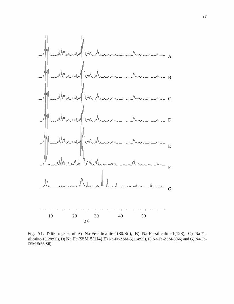
silanisation. Powder XRD results showed that only the ZSM-5 phase was obtained. The second
type was synthesized by encapsulation of Fe-TPP (tetraphenylporphyrin) inside faujasite Y to
produce Fe-TPP-NaY. Powder XRD results confirmed the faujasite structure after encapsulation.
Finally, Fe-MOF-5(1), Fe-Zn-MOF-5(0.5) and Fe-Zn-MOF-5(0.2) were synthesized using
conventional methods with the numbers in brackets representing the Fe wt%. Also, XRD results
showed that the MOF-5 phase was obtained with a sharp peak at 2θ below 10° which is
characteristic of a highly crystalline material. All synthesized catalysts were tested in the
oxidation of n-octane to oxygenates with H2O2 as the oxidant in MeCN. Furthermore, Fe-TPP-
NaY was also used to activate 1-octene, 4-octene and cyclohexane while Fe-MOF-5 was used to
activate cyclohexane. Na-Fe-silicalite-1(34), H-Fe-silicalite-1(34) and Na-Fe-silicalite-1(68)
produced selectivities of 24, 2 and 27% respectively to terminal products at 80 °C in 13 mL
MeCN. Furthermore, Na-Fe-silicalite-1(41), Na-Fe-silicalite-1(80), Fe-silicalite-1(128), Na-Fe-
ZSM-5(66) and Na-Fe-ZSM-5(114) achieved selectivities to terminal products of 20.2, 28.1,
17.6, 24.5 and 21.3 respectively while Na-Fe-silicalite-1(41:Sil), Na-Fe-silicalite-1(80:Sil), Na-
Fe-silicalite-1(128:Sil), Na-Fe-ZSM-5(66:Sil) and Na-Fe-ZSM-5(114:Sil) showed selectivities to
terminal products of 20.7, 14.3, 12.3, 25.7 and 27.3 % respectively at 80 °C in 80 mL MeCN.
Fe-TPP-NaY showed 13% selectivity to terminal products in oxidation of n-octane at 80 C in 13
mL MeCN. In the oxidation of n-octane using Fe-MOF-5 catalysts, selectivity to terminal
products was found to increase with a decrease in the wt% of Fe. Hence, selectivities of 9.5,
12.9 and 20.7% were recorded for Fe-MOF-5(1), Fe-Zn-MOF-5(0.5) and Fe-Zn-MOF-5(0.2)
respectively.
Page 3
iii
PREFACE
All the experimental work described in this thesis was performed at University of KwaZulu-
Natal in the School of Chemistry & Physics, Westville Campus, Durban. The experimental work
was done from July 2010 to January 2013 under the supervision of Prof. H. B. Friedrich and Dr.
M. D. Bala.
The work presented in this thesis represents original work by the author that has not been done or
published elsewhere by others. The work of others that has been used in this work is fully
acknowledged.
_________________ Mduduzi N. Cele
MSc (UKZN)
Page 4
iv
ACKNOWLEDGEMENTS First of all, I would like to take the opportunity to thank the Lord, through thick and thin, through
pain and joy his words kept me going. I can do all things through Christ the Lord.
Secondly, I would also like to thank my supervisors Prof. H. B. Friedrich and Dr. M. D. Bala for
guiding and advising me. I would like to thank C* Change, NRF and THRIP for funding my
studies.
Furthermore, I would like to thank the following: Catalysis Research Group for their support,
Miss J. Naidoo for handling my financial matters. Also thank the EM unit at University of
KwaZulu-Natal (Westville Campus) for SEM, EDS and TEM analysis and the Geology
department for XRD and XRF analysis.
Page 5
v
COLLEGE OF AGRICULUTRE, ENGINEERING AND SCIENCE
DECLARATION - PLAGIARISM
I, ___________________________________________ declare that
1. The research reported in this thesis, except where otherwise indicated is my original
research.
2. This thesis has not been submitted for any degree or examination at any other
university.
3. This thesis does not contain other persons’ data, pictures, graphs or other information,
unless specifically acknowledged as being sourced from other person.
4. This thesis does not contain other persons’ writing, unless specifically acknowledged
as being sourced from other researchers. Where other written sources have been
quoted, then:
a. Their words have been re-written but the general information attributed to
them has been referenced.
b. Where their exact words have been used, then their writing has been placed in
italics and inside quotation marks, and referenced.
5. This thesis does not contain text, graphics or tables copied and pasted from the
Internet, unless specifically acknowledged, and the source being detailed in the thesis
and in the References sections.
Signed: _________________________
Page 6
vi
CONFERENCE CONTRIBUTIONS AND PUBLICATIONS
The following conferences have been attended where part of this work was presented:
CATSA Conference 2007, Richard’s Bay, presented a poster entitled “Biomimetic oxidation of
paraffins to oxygenates using Fe-X-ZSM-5 (X: H, Na, K)”
CATSA Conference 2008, Parys, presented a poster entitled “Biomimetic oxidation of paraffins
to oxygenates using Fe-X-ZSM-5 (X: H, Na, K)”
CATSA Conference 2009, Goudini Spa, presented a poster entitled “Biomimetic oxidation of
paraffins to oxygenates using Fe-X-ZSM-5 (X: H, Na, K)”
British Zeolite Association Conference 2009, Ambleside, UK presented a poster entitled
“Biomimetic oxidation of paraffins to oxygenates using Fe-X-ZSM-5 (X: H, Na, K)”
A paper entitled “A study of Fe(III)TPPCl encapsulated in zeolite NaY and Fe(III)NaY in the oxidation of n-octane, cyclohexane, 1-octene and 4-octene” Reac. Kinet. Mech. Cat. 111 (2014) 737 A paper entitled “Liquid phase oxidation of n-octane to C8 oxygenates over modified Fe-MOF-5
Catalysts” Catal. Commun. 57 (2014) 99
Page 7
vii
ABBREVIATIONS
ATR = Attenuated Total Reflectance
BET = Brunauer-Emmet-Teller (surface area measurement technique)
EDS = Energy Dispersive Spectroscopy
FT-IR = Fourier Tranform-Infrared
g = Gram
GC = Gas Chromatography
ICP-OES = Inductively Coupled Plasma-Optical Emission Spectroscopy
L = Litre
M = Molar (mole/litre)
mg = Milligrams
Min = Minutes
mL = Millilitre
mm = Millimeter
SEM = Scanning Electron Mictroscopy
TEM = Transmission Electron Microscopy
TEOS = Tetraethyoxysiline
XRD = X-Ray Diffraction
XRF = X-Ray Fluorescence
Å = Angstroms
MOF = Metal Organic Framework
ZSM-5 = Zeolite Socony Mobil number 5
Page 8
viii
LIST OF FIGURES
Fig. 1.1: Shape selectivity of zeolite shows (a) Reactant, (b) Product and (c) Transition
state selectivity 4
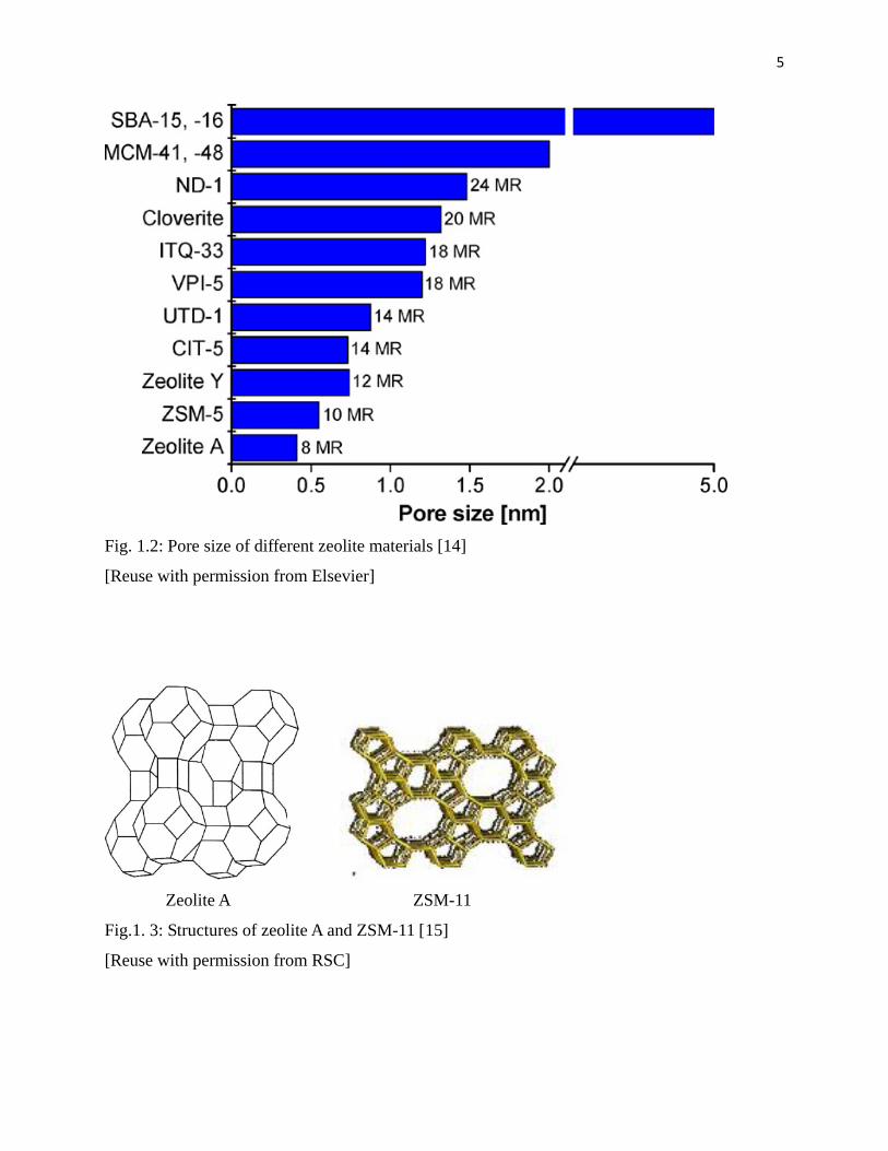
Fig. 1.2: Pore size of different zeolite materials 5
Fig. 1.3: Structures of zeolite A and ZSM-11 6
Fig. 1.4: ZSM-5 structure to illustrate the intersection of channels 6
Fig. 1.5: Structure of zeolite Y 7
Fig. 1.6: The structure of Cytochrome p450 8
Fig. 1.7: Cytochrome p450 mechanism 9
Fig. 1.8: Proposed mechanism of the activation of a substrate R-H using TS-1 10
Fig. 1.9: Encapsulation of Fe-TPP into NaY 15
Fig. 1.10: Porphyrin a) tetraphenylporphyrin (TPP), b) meso-
tetrakis(pentafluorophenyl)porphyrin (TPFPP) and c) meso-tetrakis(2,6-
dichlorophenyl)-β-octabromoporphyrin (Br8TDCPP) 17
Fig. 1.11: MOF-5 structure 20
Fig. 2.1: X-Ray Diffractogram of A) Na-Fe-silicalite-1(34), B) H-Fe-silicalite-1(34)
and C) Na-Fe-silicalite-1(68) 35
Fig. 2.2: SEM image of Na-Fe-silicalite-1(34) 36
Fig. 2.3: TEM image of Na-Fe-silicalite-1(34) 36
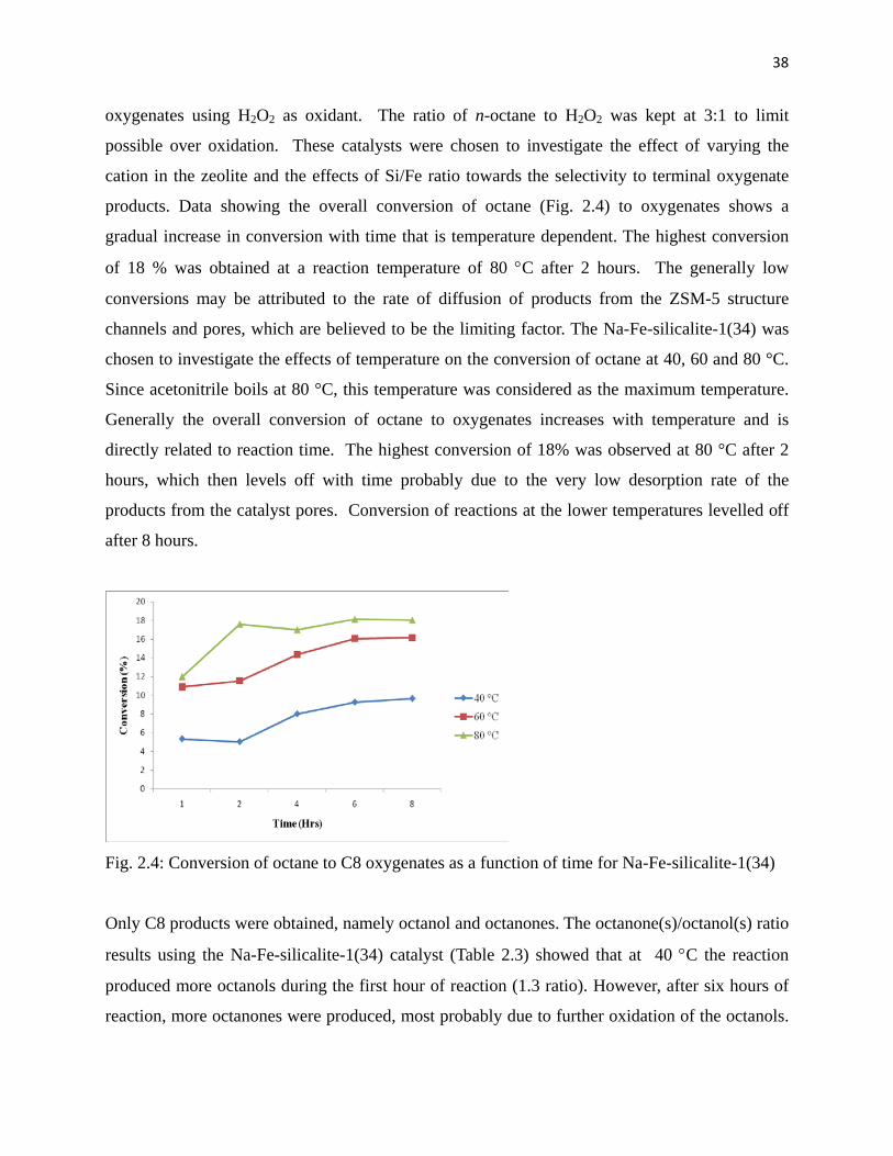
Fig. 2.4: Conversion of octane as a function of time for Na-Fe-silicalite-1(34) 38
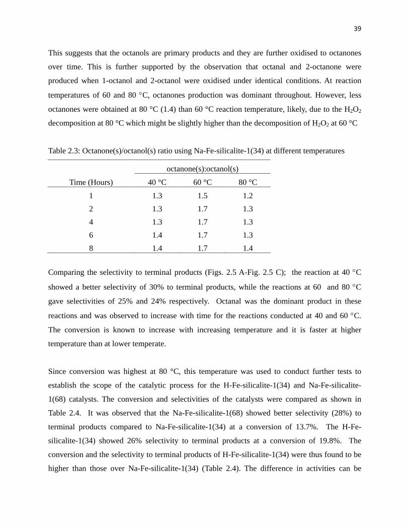
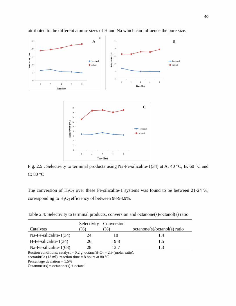
Fig. 2.5: Selectivity to terminal products using Na-Fe-silicalite-1(34) at A: 40 °C, B: 60 °C
and C: 80 °C 40
Fig. 2.6: Na-Fe-silicalite-1(34) reaction products distribution 42
Fig. 3.1: Diffractogram of A) Na-Fe-silicalite-1(41), B) Na-Fe-silicalite-1(41:Sil) and C)
Na-Fe-ZSM-5(66) 51
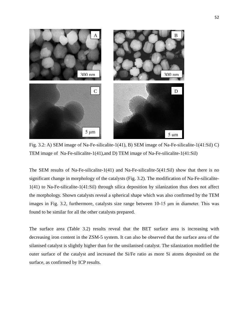
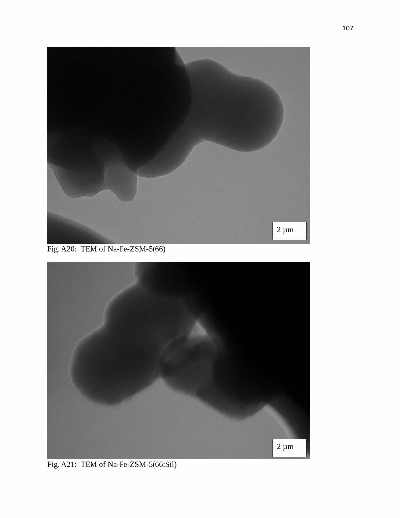
Fig. 3.2: A) TEM image of Na-Fe-silicalite-1(41), B) SEM image of Na-Fe-silicalite-1(41),
C) SEM image of Na-Fe-silicalite-1(41:Sil) and D) TEM image of
Na-Fe-silicalite-1(41:Sil) 52
Page 9
ix
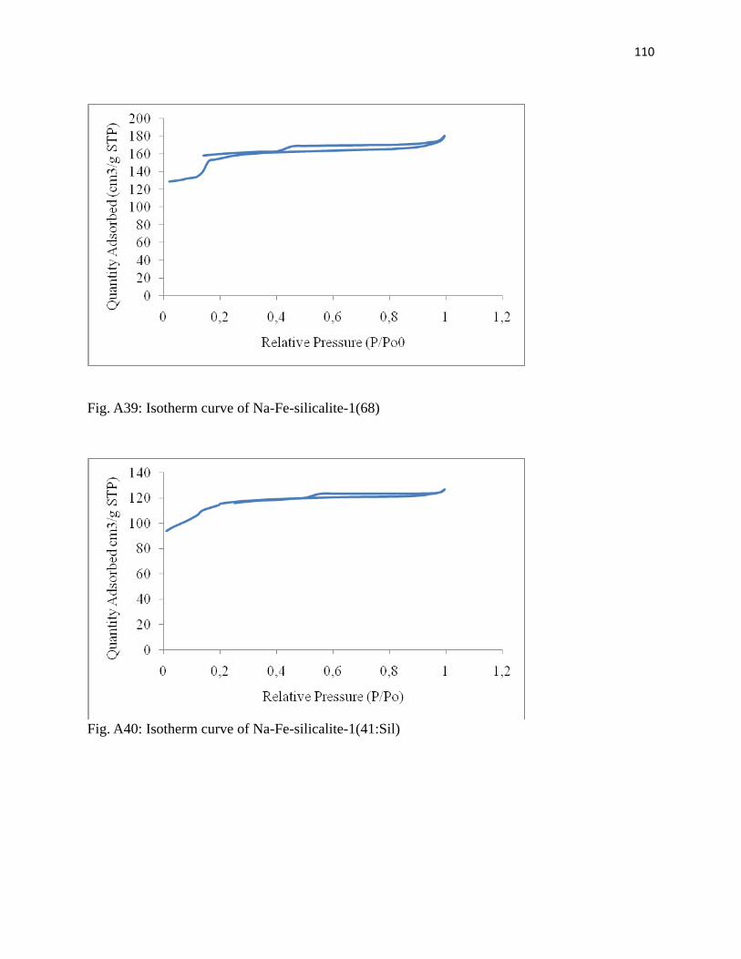
Fig. 3.3: Isotherm curve of Na-Fe-silicalite-1(41) 54
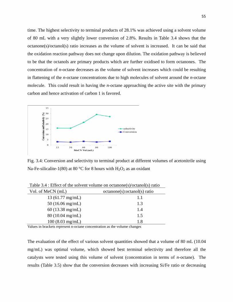
Fig. 3.4: Conversion and selectivity to terminal product at different volume of acetonitrile
using Na-Fe-silicalite-1(80) at 80 °C for 8 hours 55
Fig.3.5: Products distribution over (A) Na-Fe-silicalite-1(41) and
(B) Na-Fe-silicalite-1(41:Sil) 57
Fig.3.6: Products distribution over (A) Na-Fe-ZSM-5(114) and
(B) Na-Fe-ZSM-5(114:Sil) 58
Fig. 4.1: FTIR of A) H2TPP and B) FeTPP 66
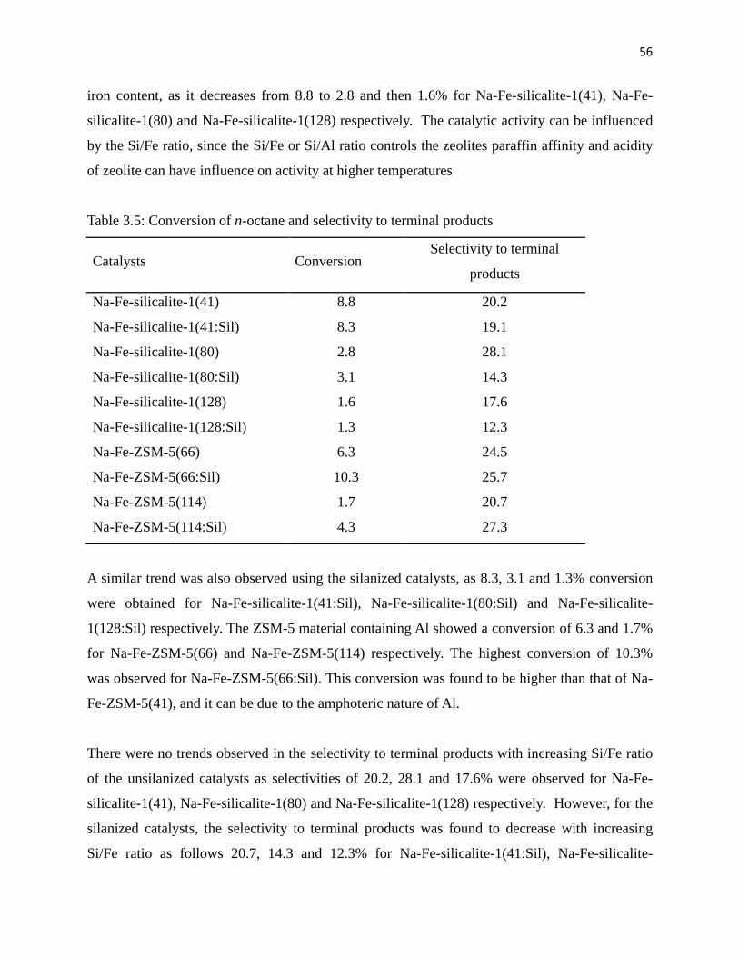
Fig. 4.2: 1H NMR of H2TPP 67
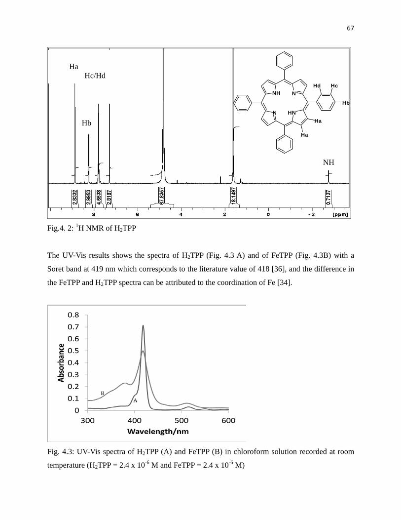
Fig. 4.3: UV-Vis spectra of H2TPP (A) and (B) FeTPP in chloroform solution recorded at
room temperature (H2TPP = 2.4 x 10⁻⁶ M and FeTPP = 2.4 x 10⁻⁶ M) 67
Fig. 4.4: Powder XRD patterns of (A) NaY, (B) Fe-NaY, (C) Fresh FeTPP-NaY and (D)
used FeTPP-NaY 69
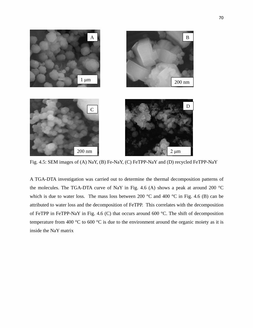
Fig. 4.5: SEM images of (A) NaY, (B) Fe-NaY , (C) FeTPP-NaY and (D) used FeTPP-NaY 70
Fig. 4.6: DSC-TGA curves of (A) NaY, (B) FeTPP and (C) Fe-TPP-NaY 71
Fig. 4.7: Products distribution over (A) Fe-TPP-NaY (fresh) and (B) Fe-TPP-NaY (recycled) 76
Fig. 4.8: MeCN solution after reaction using Fe-TPP-NaY (A), Fe-TPP in MeCN (B) 77
Fig. 4.9: Products distribution over (A) Fe-NaY (fresh) and (B) Fe-NaY (recycled) 78
Fig. 5.1: Powder X-Ray Diffractograms of A) Fe-MOF-5(1), B) Fe-Zn-MOF-5(0.5) and
(C ) Fe-Zn-MOF-5(0.2) 85
Fig. 5.2: Fig. 5.2: A) SEM image of A) Fe-MOF-5(1), B) Fe-Zn-MOF-5(0.5),
C) Fe-Zn-MOF-5(0.2) and TEM images of D) Fe-MOF-5(1), E) Fe-Zn-MOF-5(0.5)
and F) Fe-Zn-MOF-5(0.2) 86
Fig. 5.3: Powder X-Ray Diffractogram of used Fe-MOF-5(1) 89
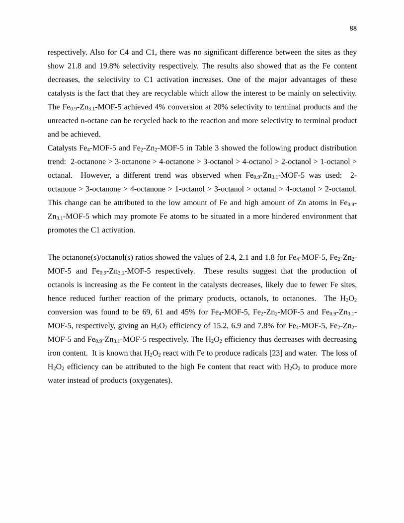
Fig. 5.4: Images A) SEM and B) TEM of used Fe-MOF-5(1) 90
Page 10
x
LIST OF SCHEMES
Scheme 1.1: Illustrating the production of oxygenates 2
Scheme 1.2: An illustration of isomorphic substitution 12
Scheme 1.3: An illustration of ion exchange 13
Scheme 1.4: General synthesis of MOF using a conventional method 18
Scheme 1.5: General synthesis of MOF using unconventional method 19
Page 11
xi
LIST OF TABLES Table 1.1: Cavity sizes of different MOFs 21
Table 1.2: Comparison of selectivity to terminal products 24
Table 1.3: Oxidation of cyclohexane 24
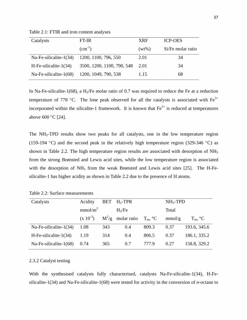
Table 2.1: FTIR and iron content analysis 37
Table 2.2: Surface measurements 37
Table 2.3: Octanone(s)/octanol(s) ratio using Na-Fe-silicalite-1(34) at different
temperatures 39
Table 2.4: Selectivity to terminal products, conversion and octanone(s)/octanol(s) ratio 40
Table 2.5: Selectivity to terminal products, conversion and octanone(s)/octanol(s) using
high H2O2 concentration 41
Table 3.1: FT-IR results of the catalysts 51
Table 3.2: Surface properties and ICP results 53
Table 3.3: H2-TPR and NH3-TPD results 54
Table 3.4: Effect of the solvent volume on octanone(s)/octanol(s) ratio 55
Table 3.4: Conversion and selectivity to terminal products 56
Table 4.1: Elemental analysis of H2-TPP and Fe-TPP 68
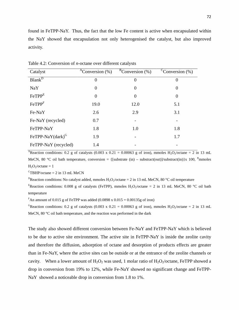
Table 4.2: Conversion of n-octane over different catalysts 72
Table 4.3 A: Product distribution using higher H2O2 concentration 73
Table 4.3 B: Product distribution using lower H2O2 concentration 73
Table 4.3 C: Product distribution using TBHP as an oxidant 74
Table 5.1: FT-IR and BET results of MOF-5 catalysts 85
Table 5.2: Oxidation of n-octane using Fe-MOF-5 catalysts 86
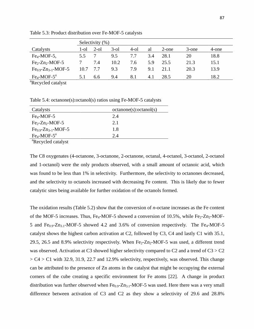
Table 5.3: Product distribution over Fe-MOF-5 catalysts 87
Table 5.4: Octanone(s):octanol(s) ratios using Fe-MOF-5 catalysts 87
Table 5.5: Oxidation of cyclohexane using Fe-MOF-5 catalysts 89
Page 12
xii
CONTENTS Title i
Abstract ii
Preface iii
Acknowledgements iv
Declaration plagiarism v
Conference contributions and publications vi
Abbreviations vii
List of Figures viii
List of Schemes x
List of Tables xi
Content xii
Chapter one 1
Introduction and literature review
1.Introduction 1 1.1. Zeolites 3
1.1.1 Shape selectivity of zeolite 4
1.1.2 Zeolite structures 5
1.1.3 ZSM-5 zeolite 6
1.1.4 Faujasite zeolite 7
1.2 Biomimetic 8
1.2.1 ZSM-5 systems 11
1.2.2 Faujasite systems 15
1.2.3 Metal Organic Framework (MOF) 18
1.3 Selectivity to terminal products 21
1.4 Aims of the project 25
References 25
Chapter two 29
Peroxide oxidation of n-octane over Na-Fe-silicalite-1 and
Page 13
xiii
H-Fe-silicalite-1 catalysts Abstract 29
2.1. Introduction 30
2.2. Experimental 31
2.2.1 Catalyst synthesis 31
2.2.2 Characterisation 32
2.2.3 Catalyst testing 33
2.2.4 Oxidation of n-octane in present of cyclohexane 33
2.3. Results and Discussion 34
2.3.1 Catalyst characterisation 34
2.3.2 Catalyst testing 37
2.3.3 Oxidation of n-octane in present of cyclohexane 42
2.4. Conclusions 43
Acknowledgements 43
References 44
Chapter three 46
Evaluation of silanization of Fe-silcalite-1, Na-Fe-ZSM-5 and
solvent concentration on the oxidation of n-octane to C8 oxygenates Abstract 46
3.1. Introduction 46
3.2. Experimental 47
3.2.1 Catalyst synthesis 47
3.2.2 Characterisation 49
3.2.3 Catalyst testing 49
3.2.4 Oxidation of n-octane in present of cyclohexane 50
3.3. Results and Discussion 50
3.3.1 Catalyst characterisation 50
3.3.2 Catalytic testing 54
3.3.3 Oxidation of n-octane in present of cyclohexane 58
Page 14
xiv
3.4. Conclusion 58
Acknowledgements 59
References 59
Chapter four 61
A study of Fe(III)TPPCl encapsulated in zeolite NaY and Fe(III)NaY
in the oxidation of n-octane, cyclohexane, 1-octene and 4-octene Abstract 61
4.1. Introduction 61
4.2 Experimental 63
4.2.1 Materials 63
4.2.2 Synthesis of free base H2TPP 63
4.2.3 Synthesis of FeTPP 63
4.2.4 Synthesis of Fe-NaY and FeTPP-NaY 64
4.2.5 Characterization of the catalysts 64
4.2.6 Catalytic testing 65
4.3 Results and discussion 65
4.3.1 Characterization of FeTPP 65
4.3.2 Characterization of Fe-NaY and FeTPP-NaY 68
4.3.3 Catalytic testing 71
4.3.4 Recycling FeNaY and FeTPP-NaY 76
4.4. Conclusion 78
Acknowledgements 78
References 78
Chapter five 81
Liquid phase oxidation of n-octane to C8 oxygenates over modified Fe-MOF-5
catalysts Abstract 81
5.1. Introduction 81
Page 15
xv
5.2 Experimental 82
5.2.1 Materials 82
5.2.2 Synthesis of Fe-MOF-5 82
5.2.3 Catalysts characterization 83
5.2.4 Catalytic testing 83
5.3. Results and discussion 84
5.3.1 Catalyst characterisation 84
5.3.2 Catalytic testing 86
5.3.3 Recycling and leaching test of Fe-MOF-5(1) 89
5.4. Conclusion 90
Acknowledgements 91
References 91
Chapter six 93
Summary and Conclusion
Appendix 95
Page 16
1
Chapter one Introduction and literature review
1. Introduction
The depletion of non-renewable crude oil resources around the world has increased dramatically
over the last few decades. Over-reliance on natural crude oil has increased the cost of oil and
petroleum products derived from it [1]. Also the process of its refining into useful products is
very intense, as most of the crude comes contaminated with a high content of S, N, and other
inorganic metallic pollutants. In addition, there are environmental policies and regulations that
regulate the emission of these contaminants into the atmosphere [2]. There is a limited amount of
contaminants that are tolerated, particularly in fuels. These regulations force refineries to process
crude oil intensively. This comes with associated financial implications and environmental
issues. In spite of these, the world energy supply is still strongly dependent on extraction and
refining of crude oil. High demand of energy has encouraged researchers to seek alternative
technologies for processing renewable or more abundant alternative substances [3].
Paraffins are one of the most abundant substances on earth and are found as liquid paraffins or
mineral oil, which is a mixture of high carbon number alkanes. They are also found in natural
gas, as methane. Most importantly, there are many technologies and processes that produce
paraffins as by-products or as the main products [4-6]. However, paraffins on their own have
limited application because of their low reactivity. They are commonly used as anti-caking
additives, in electrical and electronic applications, as additives in tyre production, in lotions,
pastes, cream, lipsticks, used in printing inks and varnishes, candle production, and as a
lubricant. This is due to their low acidity, basicity and strong C-H bond strength [7].
In today’s world of intensive energy demand, there is a strong demand for processes that convert
paraffins to more useful products. Furthermore, functionalized paraffins have a wide range of
applications as compared to simple paraffin. Functional groups, such as -OH or -Br, are
incorporated into paraffins in order to produce more useful materials. Scheme 1.1 illustrates the
activation of paraffin using a variety of catalytic methodologies including homogeneous,
Page 17
2
heterogeneous and bio catalysis to more value-added products, like oxygenates.
OH
OH
CATALYSIShomogenous
heterogeneous
biocatalysis
HO
Scheme 1.1: Illustrating the production of oxygenates
Oxygenates are obtained by inserting O into the hydrocarbon structure of the paraffin. This
means the inactive C-H bond of the paraffin is activated, and the resultant product, oxygenate,
has many applications such as use as a solvent or in gasoline. Linear oxygenates have been
reported to be useful in the chemical and pharmaceutical fields [8]. Some oxygenates are used in
gasoline as an addictive in order to improve the octane number [9-10]. Furthermore, it has been
reported that the addition of oxygenates into diesel fuels help to reduce harmful emissions. Thus,
oxygenates, like ethanol, carbonates, ethers and diglyme have been reported to reduce emission
[11]. The application of terminal oxygenates has been found to be most important in the fine
chemical and pharmaceutical industry, where they are mainly used as plasticizers and detergents.
There are many different types of techniques that are used to activate and functionalize paraffins.
Page 18
3
These techniques use different types of materials like zeolites, clays, monoliths, hydrotalcite etc.
1.1 Zeolites
A zeolite is a crystalline aluminosilicate material or mineral that occurs naturally. There are many
different types of zeolites that are available today. They come in different shapes and forms e.g.
ZSM-5, faujasites, mordenite, zeolite beta, chabazite and ferrierite. Zeolites are commonly
classified according to their pore sizes into micropores (pore diameter ≤ 2 nm), mesopores (2 nm
< pore diameter ≤ 50 nm) and macropores (pore diameter ≥ 50 nm) [1 2]. They possess a very
unique physical property that makes them more useful than other materials, like monoliths.
Their structure, channels and cavities are properties that lead to shape selectivity behaviour that
is important in the field of catalysis [13].
1.1.1 Shape selectivity of zeolite
One of the very unique properties of zeolites is shape selectivity since a zeolite contains channels
and cavities of specific dimensions. Shape selectivity can be used to control the preferential
production (selectivity) of a specific product and govern the use of a substrate or oxidant. There
are three important aspects of shape selectivity [12]:
i) Reactant shape selectivity (Fig. 1.1a): This is mainly dependent on the size of the
reactant, the bigger reactant molecules are excluded or do not enter the pore of the
zeolite. This means that if the active site is inside the channels, the reactants that do
not enter the channels do not react. Using the reactant shape selectivity concept, one
can control which reactants or substrates will react at the active site within the
channels.
ii) Product shape selectivity (Fig. 1.1b): This is controlled by the available space inside the
channels or cavity. The channels can restrict the formation of bulky products
depending on the dimension or diameter of the channels. Also a specific orientation
of the substrate will be favored which will constitute or promote the formation of a
specific product.
iii) Restricted transition state shape selectivity (Fig. 1.1c): The formation of a bulky
transition state is restricted inside the channels or cavities. This usually minimizes
Page 19
4
the formation of bulky products from the zeolite. The restricted transition state shape
selectivity is mainly dependent on the crystal size of the zeolite.
Depending on the desired products and reactants, shape selectivity can be tuned to drive a
reaction in a required direction. Furthermore, one can choose from a wide range of zeolite types
that possess pores size for a specific reaction.
+
CH3OH +
Fig. 1.1: Shape selectivity of zeolite shows (a) Reactant, (b) Product and (c) Transition state
selectivity [12]
1.1.2 Zeolite structure
There are many different zeolite structures that are currently used in the field of catalysis.
Fig.1. 2 shows some zeolite types and their pore sizes [14]. Zeolite A and ZSM-11 (Fig. 1.3) are
the most widely used in catalytic applications.
a
b
c
Page 20
5
Fig. 1.2: Pore size of different zeolite materials [14]
[Reuse with permission from Elsevier]
Zeolite A ZSM-11
Fig.1. 3: Structures of zeolite A and ZSM-11 [15]
[Reuse with permission from RSC]
Page 21
6
1.1.3 ZSM-5 zeolite
The ZSM-5 (Fig. 1.4) zeolite type belongs to the pentasil family of zeolites. It consist of a three
dimensional structure of an aluminosilicate material with 10 membered rings that are linked
together by O atoms. The average pore size of the channels ranges between 5.4 – 5.6 Å, and the
Si/Al ratio that can be change from 12 to almost ∞ [1 6]. An additional cation, like H+, is
required to balance the charges. There are many industrial processes today that use solid ZSM-5
as a catalyst e.g. isomerisation and Fischer Tropsh
Fig. 1.4: ZSM-5 structure to illustrate the intersection of channels [17]
[Reuse with permission from RSC]
This type of zeolite is reported to be stable to a temperature above 1000 °C and has a high acid
stability. The acidity of the ZSM-5 can be controlled by varying the Al3+ content. Also, the
hydrophobic behavior can be easily modified [16].
1.1.4 Faujasite zeolite
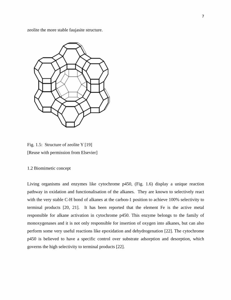
Faujasite (Fig. 1.5) has a three dimensional pore structure with a pore size of 7.4 Å. It is
composed of a 12 membered ring structure with a cavity of 12 Å in size [18] and belongs to a
silicate mineral group with faujasite-Na, faujasite-Mg and faujasite-Ca being commonly known.
Zeolite X and Y are widely used and the Si/Al ratio of the framework structure determines the
type of structure formed. The X zeolite has a ratio of 2-3, while 3 and higher produces the Y
zeolite. The stability of faujasite increases with an increase in Si/Al ratio which makes the Y
Page 22
7
zeolite the more stable faujasite structure.
Fig. 1.5: Structure of zeolite Y [19]
[Reuse with permission from Elsevier]
1.2 Biomimetic concept
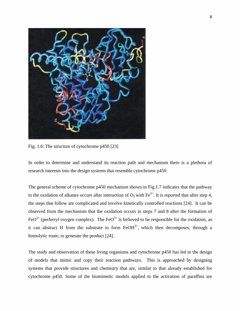
Living organisms and enzymes like cytochrome p450, (Fig. 1.6) display a unique reaction
pathway in oxidation and functionalisation of the alkanes. They are known to selectively react
with the very stable C-H bond of alkanes at the carbon-1 position to achieve 100% selectivity to
terminal products [20, 21]. It has been reported that the element Fe is the active metal
responsible for alkane activation in cytochrome p450. This enzyme belongs to the family of
monoxygenases and it is not only responsible for insertion of oxygen into alkanes, but can also
perform some very useful reactions like epoxidation and dehydrogenation [22]. The cytochrome
p450 is believed to have a specific control over substrate adsorption and desorption, which
governs the high selectivity to terminal products [22].
Page 23
8
Fig. 1.6: The structure of cytochrome p450 [23]
In order to determine and understand its reaction path and mechanism there is a plethora of
research interests into the design systems that resemble cytochrome p450.
The general scheme of cytochrome p450 mechanism shown in Fig.1.7 indicates that the pathway
to the oxidation of alkanes occurs after interaction of O2 with Fe3+. It is reported that after step 4,
the steps that follow are complicated and involve kinetically controlled reactions [24]. It can be
observed from the mechanism that the oxidation occurs in steps 7 and 8 after the formation of
FeO3+ (perferryl oxygen complex). The FeO3+ is believed to be responsible for the oxidation, as
it can abstract H from the substrate to form FeOH3+, which then decomposes, through a
homolytic route, to generate the product [24].
The study and observation of these living organisms and cytochrome p450 has led to the design
of models that mimic and copy their reaction pathways. This is approached by designing
systems that provide structures and chemistry that are, similar to that already established for
cytochrome p450. Some of the biomimetic models applied to the activation of paraffins are
Page 24
9
further discussed below.
Fe3+
Fe2+-O2. RH
Fe2+ RH
Fe2+ -O2 RH
Fe3+ RH
FeII-OOHRH
Fe3+ ROH
FO3+ RH
FeOH3+ R•
•
NADPH-P450 reductase red
1e- 2.
NADPH-P450 reductase ox
O2 3.
NADPH-P450 reductase red
1 e- 4.
NADPH-P450 reductase oxH+5.
6. -H2O
7.
8.
9.
10.R'O or R'OOH
RH
-ROHRH 1.
Fig. 1.7: Cytochrome p450 mechanism [25]
[Reuse with permission from Elsevier]
Titanium silicalite-1 (TS-1) materials are titanium based compounds of a high silica zeolite with
the MFI or ZSM-5 structure. This is one of the systems that are believed to have a reaction path
that is closely related to the mode of action of cytochrome p450.
The proposed mechanism (Fig. 1.8) of TS-1 using H2O2 shows that the formation of titanyl and
peroxotitanium groups are very important intermediate species for the oxidation of paraffins.
The oxidation of paraffin occurs after radical formation on the titanyl species. TS-1 has been
reported to achieve a C-2 > C-3 > C-4 selectivity trend with no C-1 activation observed in the
oxidation of octane using H2O2 [27]. The TS-2 (titanium silicate with MEL structure) catalyst
was reported to produce 65 and 25% selectivities to cyclohexanol and cyclohexanone
Page 25
10
respectively in the oxidation of cyclohexane using H2O2 as an oxidant [26].
The catalysis of Na-V-ZSM-5, which was synthesised using ionic exchange, was investigated in
the oxidation of hexane where a selectivity of 1.6% to 1-hexanol was reported [27]. The
vanadium silicates VS-2 were also used in the oxidation of hexane using H2O2 where a 32%
selectivity to terminal products was reported [28]. A selectivity of 24% to terminal product in
the oxidation of hexane using Mn-ZSM-5, which was prepared using ionic exchange, was also
reported [29].
Fig. 1.8: Proposed mechanism of the activation of a substrate R-H using TS-1[30]
[Reuse with permission from Elsevier]
1.2.1 ZSM-5 systems
Due to the activities gained from the use of active metals in zeolites, the synthesis of zeolites
incorporating active metals has been an area of active research [31]. The incorporation of active
metals into a matrix like zeolite provides the field of catalysis with some benefits, like ease of
recovery of the metal. This approach of incorporation helps to heterogenise the metal by
entrapping it within the matrix; furthermore, the matrix used provides substrate and product
shape selectivity. The main challenge comes when one needs to control the degree of dispersion
of the elements within the matrix. There are several methods that are used to incorporate a
transition element into a zeolite matrix with the three most routinely used being: i) isomorphic
substitution, [32] ii) ionic exchange and chemical vapor deposition (CVD) [33].
Page 26
11
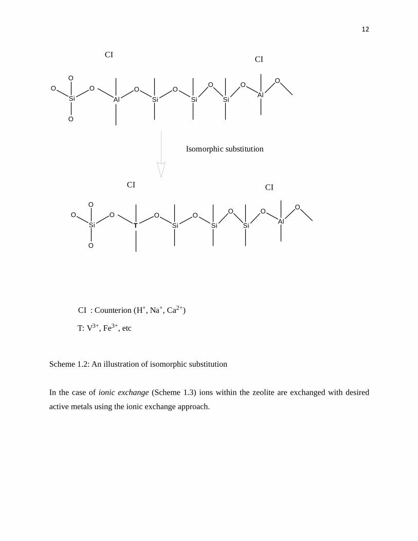
Isomorphic substitution (Scheme 1.2) involves the addition of active metals during the synthesis
of the desired zeolite. This results in the incorporation of the desired elements within the
framework structure of the zeolite. The incorporation of active metals is influenced by synthetic
conditions like pH and the amount of transition elements used.
It has been reported that the use of high amounts of active metals can lead to formation of a
conglomerate that usually occupies the extra-framework position of the zeolite as metal oxide.
Furthermore, the nature and the position of these metal oxide species are believed to have a very
high influence on catalytic reaction behaviour. Therefore, it is very important to define the
synthetic conditions in order to obtain a desired catalyst.
Page 27
12
SiOO
O
O
AlO
SiO
Si
O
Si
OAl
O
SiOO
O
O
TO
SiO
Si
O
Si
OAl
O
Isomorphic substitution
CI CI
CI CI
CI : Counterion (H+, Na+, Ca2+)
T: V3+, Fe3+, etc
Scheme 1.2: An illustration of isomorphic substitution
In the case of ionic exchange (Scheme 1.3) ions within the zeolite are exchanged with desired
active metals using the ionic exchange approach.
Page 28
13
SiOO
O
O
AlO
SiO
Si
O
Si
OAl
O
SiOO
O
O
AlO
SiO
Si
O
Si
OAl
O
CI CI
T T
Ionic exchange
T: V3+, Fe3+, etc.
Scheme 1.3: An illustration of ionic exchange
The zeolite can be modified using an aqueous solution or by solid state ionic exchange of the
transition element at a certain temperature. The solid state ionic exchange is commonly
performed at a very high temperature compared to solution ionic exchange.
Chemical Vapor Deposition (CVD) occurs at high temperature above 600 °C. The active metals
are transported in the form of a vapor and deposited on to the targeted material. This approach is
believed to be more reproducible compared to other methods [17].
Page 29
14
i) Silanisation
In order to maximize the effect of shape selectivity that is provided by zeolites, the external
surface of the zeolite must be inactive; hence the active metals must be imbedded within the
channels and cavities of the zeolite. However, this is not always the case, because during the
incorporation of active metals into the zeolite pores, some of the metals occupy sites outside the
channels and react uncontrollably, which leads to loss in selectivity. Therefore, it is of high
interest to find ways of inertize the external surface of the zeolite. One of the most common
approaches that are used to inertize the outer surface is through the process of silanisation. This
is the deposition of alkoxy-silanes on the external surface of the zeolite. There are two well
known methods of silanisation: i) Chemical Vapor Deposition (CVD), where a silanising agent
is used in a vapor form and ii) Chemical Liquid Deposition (CLD) where a silanising agent is
used in a liquid form [34]. There are a few types of silanising agents that can be used as silicon
source, including tetramethoxysilane (TMOS) and tetraethoxysilane (TEOS) which are of
different sizes [35]. The choice of silanising agent is mainly dependent on the type of zeolite
used.
It has been reported that silanisation of materials, like zeolite, can be associated with narrowing
of the pore opening of the zeolite, however, the ZSM-5 zeolite was found to be less affected by
this phenomenon compared to other zeolites, like mordenite and beta zeolite [34]. Furthermore,
the use of calcination to remove solvent that was used during the silanisation and unreacted
silanising agent can lead to re-exposure of the transition element or aluminium that was inertised
[18]. The use of high amounts of solvent at lower temperature during silanisation can lead to
more efficient silanisation [34]
ii) Thermal treatment and calcination
The incorporation of active metals within the framework structure of zeolite as T-atoms is a very
attractive area of research. This phenomenon is regarded as a special concept in the field of
catalysis [34]. However, it is also reported that calcination and thermal treatment can cause the
migration of active metals from framework positions to extra-framework positions [36].
Page 30
15
1.2.2 Faujasite systems
Encapsulation of active metal complexes into zeolite matrix has been a growing area of research
for the past few decades [37]. The use of microporous materials to entrap metal complexes has
helped to heterogenise the chemistry of metalloporphyrin (Fig.1.9). There are two commonly
used approaches to encapsulate metalloporphyrin into zeolite matrix, like NaY and NaX, which
are: zeolite synthesis and flexible ligand [37].
Fig. 1.9: Encapsulation of Fe-TPP into NaY
Heterogenisation is achieved when a metalloporphyrin or active metal complex is added to the
zeolite during synthesis. This approach leads to the formation of the zeolite structure
encapsulating the complex, in which the complex sits in the voids or cavities of the zeolite.
N
N N
N
Fe
Page 31
16
Second is the flexible ligand method, which is when a metalloporphyrin complex is physically
diffused through the zeolite pores. Usually, once they become rigid inside the zeolite, the
complexes become too big and even in solution will not leach from the zeolite. Complexes of
Co, Mn, Fe, Rh, and Pd encapsulated in zeolite matrices were reported in different catalytic
reactions [38-40]. The use of zeolites in encapsulation of metalloporphyrins provides another
benefit, in preventing the formation of µ-oxo dimers and polymeric species, which are known to
be deactivated forms of the metalloporphyrins.
Application of metalloporphyrins as catalysts has been found in many reactions, including
oxidation and epoxidation. The area of metalloporphyrins is broad, which allows researchers to
choose one that is suitable for a particular reaction. There are different types of
metalloporphyrins that are able to provide regioselective enzyme type of reactions.
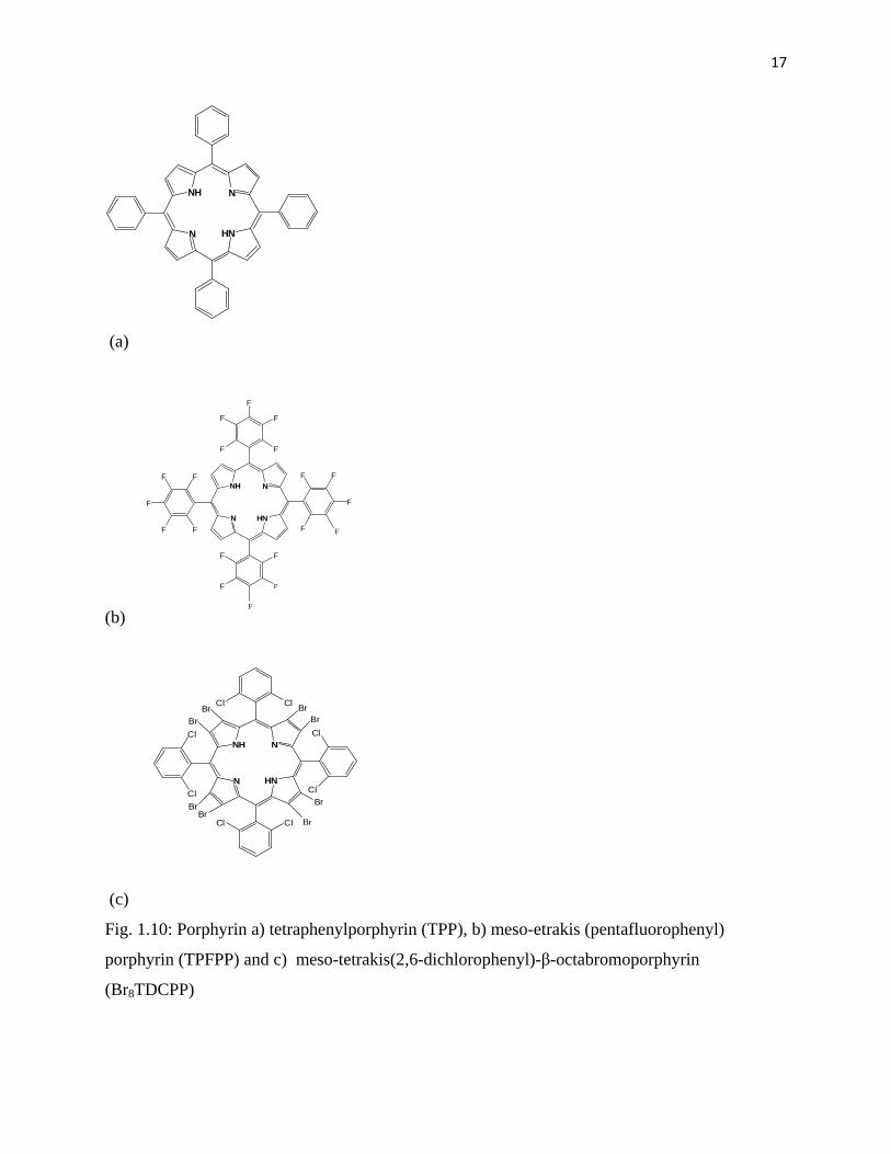
Tetraphenylporphyrin (TPP) ligand (Fig. 1.10 a) is regarded as the first generation of
metalloporphyrin where metals like Fe, Co, Ru and Mn can be inserted to produce a homogenous
catalyst. The TPP ligand was first synthesised by Adler and co-workers [41]. Furthermore,
Groves [42] was the first to report the application of metalloporphyrin containing iron in the
oxidation of alkanes using iodosylbenzene as an oxidant.
The introduction of an alkyl or halogen groups at the ortho, meta or para position of a phenyl
group that is bonded to porphyrin macrocycle resulted in the formation of a second generation of
metalloporphyrins as shown in Fig. 1.10 b [43]. This includes metalloporphyrins like meso-
tetrakis(pentafluorophenyl)porphyrin.
Page 32
17
N
NH N
HN
(a)
(b)
N
NH N
HN
F
F
F
F
F
FF
F
F
F
F
F
F
F
FF
F
F
F
F
N
NH N
HN
Cl
Cl
Cl
ClCl
Cl
Cl
Cl
BrBr
Br
BrBr
Br
BrBr
(c)
Fig. 1.10: Porphyrin a) tetraphenylporphyrin (TPP), b) meso-etrakis (pentafluorophenyl)
porphyrin (TPFPP) and c) meso-tetrakis(2,6-dichlorophenyl)-β-octabromoporphyrin
(Br8TDCPP)
Page 33
18
The third generation (Fig. 1.10 c), resulted from the introduction of halogens at the β position of
pyrroles like meso-tetrakis(2,6-dichlorophenyl)-β-octabromoporphyrin. It was reported that
these halide elements influence the Fe(III)/(II) redox couple and protect the porphyrin from
damage during an oxidation reaction [43].
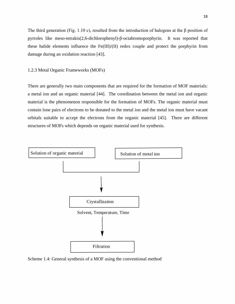
1.2.3 Metal Organic Frameworks (MOFs)
There are generally two main components that are required for the formation of MOF materials:
a metal ion and an organic material [44]. The coordination between the metal ion and organic
material is the phenomenon responsible for the formation of MOFs. The organic material must
contain lone pairs of electrons to be donated to the metal ion and the metal ion must have vacant
orbitals suitable to accept the electrons from the organic material [45]. There are different
structures of MOFs which depends on organic material used for synthesis.
Solution of organic material Solution of metal ion
Crystallization
Filtration
Solvent, Temperature, Time
Scheme 1.4: General synthesis of a MOF using the conventional method
Page 34
19
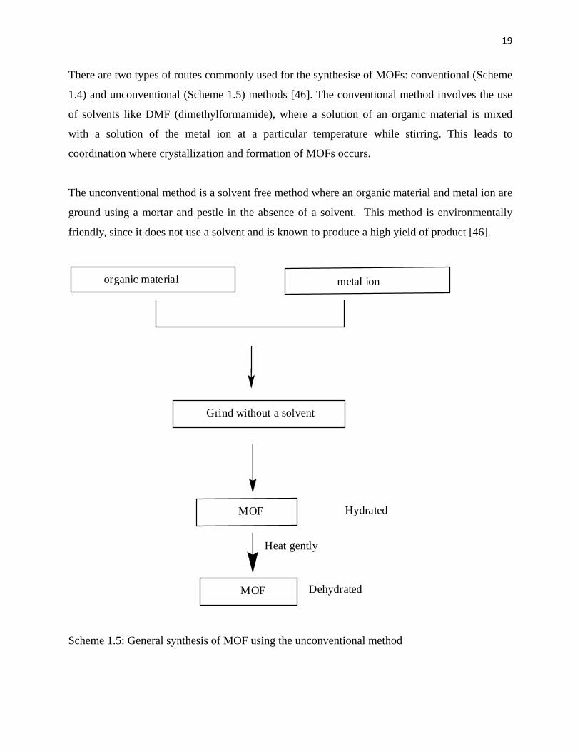
There are two types of routes commonly used for the synthesise of MOFs: conventional (Scheme
1.4) and unconventional (Scheme 1.5) methods [46]. The conventional method involves the use
of solvents like DMF (dimethylformamide), where a solution of an organic material is mixed
with a solution of the metal ion at a particular temperature while stirring. This leads to
coordination where crystallization and formation of MOFs occurs.
The unconventional method is a solvent free method where an organic material and metal ion are
ground using a mortar and pestle in the absence of a solvent. This method is environmentally
friendly, since it does not use a solvent and is known to produce a high yield of product [46].
organic material metal ion
Grind without a solvent
MOF
MOF
Hydrated
Heat gently
Dehydrated
Scheme 1.5: General synthesis of MOF using the unconventional method
Page 35
20
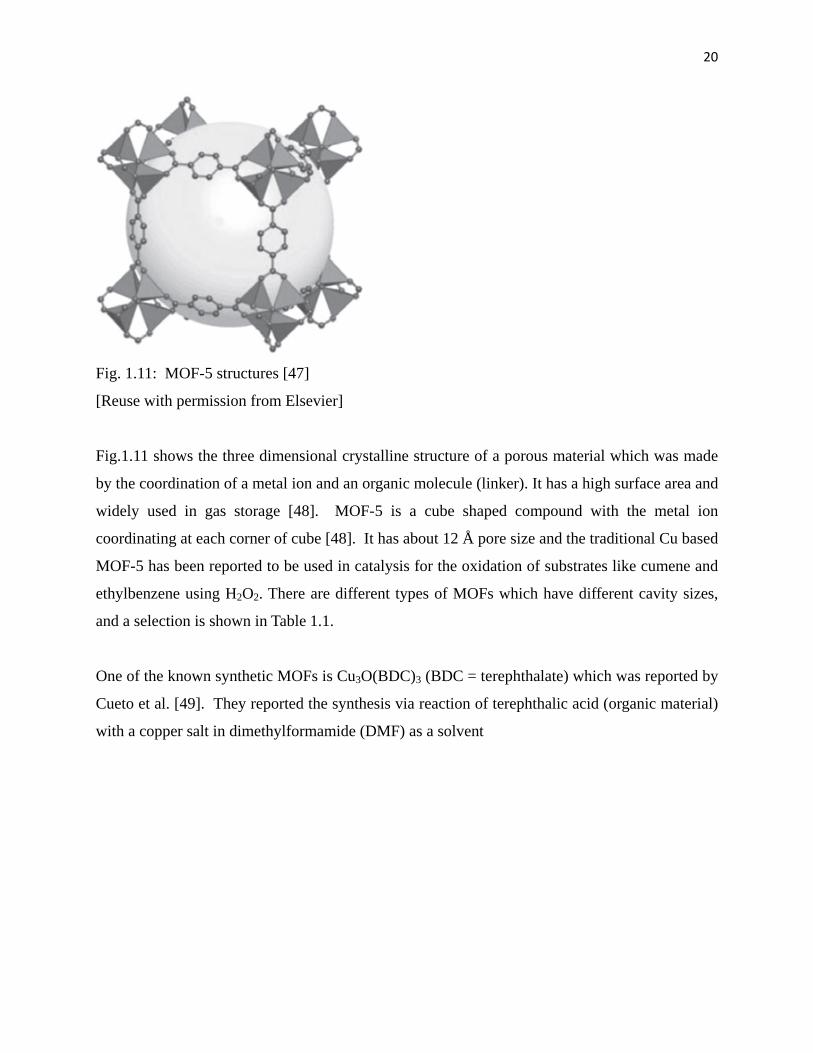
Fig. 1.11: MOF-5 structures [47]
[Reuse with permission from Elsevier]
Fig.1.11 shows the three dimensional crystalline structure of a porous material which was made
by the coordination of a metal ion and an organic molecule (linker). It has a high surface area and
widely used in gas storage [48]. MOF-5 is a cube shaped compound with the metal ion
coordinating at each corner of cube [48]. It has about 12 Å pore size and the traditional Cu based
MOF-5 has been reported to be used in catalysis for the oxidation of substrates like cumene and
ethylbenzene using H2O2. There are different types of MOFs which have different cavity sizes,
and a selection is shown in Table 1.1.
One of the known synthetic MOFs is Cu3O(BDC)3 (BDC = terephthalate) which was reported by
Cueto et al. [49]. They reported the synthesis via reaction of terephthalic acid (organic material)
with a copper salt in dimethylformamide (DMF) as a solvent
Page 36
21
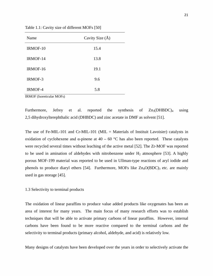
Table 1.1: Cavity size of different MOFs [50]
Name Cavity Size (Å)
IRMOF-10 15.4
IRMOF-14 13.8
IRMOF-16 19.1
IRMOF-3 9.6
IRMOF-4 5.8 IRMOF (Isoreticular MOFs)
Furthermore, Jefrey et al. reported the synthesis of Zn3(DHBDC)4 using
2,5 dihydroxylterephthalic acid (DHBDC) and zinc acetate in DMF as solvent [51].
The use of Fe-MIL-101 and Cr-MIL-101 (MIL = Materials of Instituit Lavoisier) catalysts in
oxidation of cyclohexene and α-pinene at 40 – 60 °C has also been reported. These catalysts
were recycled several times without leaching of the active metal [52]. The Zr-MOF was reported
to be used in amination of aldehydes with nitrobenzene under H2 atmosphere [53]. A highly
porous MOF-199 material was reported to be used in Ullman-type reactions of aryl iodide and
phenols to produce diaryl ethers [54]. Furthermore, MOFs like Zn4O(BDC)3 etc. are mainly
used in gas storage [45].
1.3 Selectivity to terminal products
The oxidation of linear paraffins to produce value added products like oxygenates has been an
area of interest for many years. The main focus of many research efforts was to establish
techniques that will be able to activate primary carbons of linear paraffins. However, internal
carbons have been found to be more reactive compared to the terminal carbons and the
selectivity to terminal products (primary alcohol, aldehyde, and acid) is relatively low.
Many designs of catalysts have been developed over the years in order to selectively activate the
Page 37
22
primary C-H bonded at carbon (C-1) position of linear paraffin like hexane, heptane, octane etc.
The use of titanium silicalite (TS-1) and TS-2 to oxidize linear paraffins using H2O2 has been
found to produce high amounts of oxygenates without producing terminal products. These
materials are able to produce oxygenates of the internal carbons only [26].
Cook et al. reported (Table 1.2) the oxidation of heptane and octane, in benzene as a solvent,
using iodosobenzene as an oxidant in the presence of 5, 10, 15, 20, tekrakis (2’, 4’, 6’- triphenyl
phenyl)porphyrinato-manganese(III) acetate (MnTTPPPOAc) [55]. Selectivities of 26 and 21%
to terminal products were reported for heptane and octane respectively. This is a homogeneous
system of bulky metalloporphyrin, where the issues of separation are a major limitation.
Herron used a Fe-ZSM-5 catalyst that was prepared through the ionic exchange method
(Table 1.2), and hence the Fe active sites are located at the extra framework positions of the
zeolite [56]. The oxidation of octane was performed in a solvent free system in the presence of
cyclohexane. The author reported that the use or addition of cyclohexane increased the
production of the terminal products in octane oxidation. A selectivity of 45% to terminal
products was reported in the oxidation of octane using H2O2 as an oxidant. However, the
stability of the catalyst was not reported to establish if the Fe is leaching out or not.
A possible breakthrough in the activation of paraffins was reported by Thomas et al. (Table 1.2)
where selectivity of 65% to terminal products was achieved in the oxidation of octane using air
as an oxidant over a Co/Mn-AlPO-18 zeolite catalyst [57]. It was reported that the 8-membered
ring window of the catalyst is responsible for the high selectivity to terminal products. However,
the catalyst was found to be unstable and not reproducible [57].
The use of 2, 4-dichloro-3, 5-dinitrobenzoic carboxylate Rh complexes as homogeneous
catalysts in the oxidation of hexane has been reported (Table 1.2) to produce 31% selectivity to
carbene insertion into the primary carbon of hexane [58]. Furthermore, a 65% yield to n-octyl-1-
Bpin was obtained when octane was oxidized using an HBpin (Pinacolborane) catalyst in a
homogeneous system [59].
Page 38
23
Recently, the production of methanol from methane using H2O2 as an oxidant was reported. A
selectivity of 93% to methanol was reported using Fe-ZSM-5 and Fe-Silicalite 1 as catalysts
(Table 1.2) and the oxidation is believed to be due to the extra framework Fe species formed
after heat treatment [38].
The oxidation of cyclohexane has been found to produce cyclohexanol and cyclohexanone with
the latter being the predominant product. The use of oxidants like TBHP, H2O2 and O2 has been
found to be suitable for this kind of reaction [60 - 62]. Only Au/Pd MiL-100 from Table 3 show
high selectivity to cylohexanol [63]
The highest selectivity of 65% to terminal product was achieved using zeolite MnAlPO-18 and
CoAlPO-18. However, the main setback for this system was reproducibility and stability of the
catalyst. This can be due to the soft nature of the AlPO-18 structure which tends to collapse and
release the active metal during the reaction. This can be addressed by using a hard zeolite like
NaY or ZSM-5 as matrix. The Fe-ZSM-5 was used in the oxidation of n-octane in the present of
cyclohexane. The Fe was introduced into the ZSM-5 structure by the process of ionic exchange.
However, the use of the ion exchange method can lead to leaching of the Fe into the solution to
react as a homogeneous catalyst. Therefore, framework substitution method can be used to
overcome possible leaching as the Fe will be incorporated within the structure of the ZSM-5.
One of the main challenges of the framework substitution method is that the Fe may be
incorporated in the external framework of the structure. This possibility leads to an
uncontrollable catalytic reaction which implies loss of selectivity to the desired product and
therefore defeats the purpose of using the ZSM-5 matrix. However, it can be corrected by
inertising the external surface of the catalyst using the process of silanization.
The aperture size of the ZSM-5 zeolite is 5.4 Å, and therefore it is important to evaluate the
effect of aperture size in relation to selectivity to terminal products in the oxidation of n-octane.
The use of NaY and MOF-5 with aperture sizes of 7.4 and 12 Å respectively provides the
necessary comparison
Page 39
24
Table 1.2: Comparison of selectivity to terminal products
Catalyst Substrate Solvent Oxidant
Selectivity to terminal
products (%)
Reaction temperature
( °C)
MnTTPPPOAc heptane benzene C6H5IO 26 25 [55]
MnTTPPPOAc octane benzene C6H5IO 21 25 [55]
Fe-ZSM-5 (ionic exchange) octane none H2O2 45 25 [56]
MnAlPO-18 octane none air 60+ 80 [57]
2,4 dichloro 3,5 dinitrobenzoic carboxylate Rh
complexes hexane - - 31 150 [58]
Pinacolborane (HB pin) octane - - 65 [59]
Fe-silicalite-1 methane
H2O2 93 50 [38]
Table 1.3: Oxidation of cyclohexane
Catalyst Solvent Oxidant
Selectivity (%) Reaction
temperature ( °C) cyclohexanol cyclohexanone
Fe(Salen)Y MeCN TBHP 27 73 25 [60]
bis(salicyaldehyde) oxaloyldihydrazone transition
metal complex MeCN H2O2 35.9 64.1 70 [61]
Fe-[H4] salin/Y MeCN H2O2 0 100 60 [62]
Au/Pd MIL-101 none O2 80 20 150 [63]
Page 40
25
The NaY will be used to encapsulate FeTPP (tetraphenylporphyrin) to produce a FeTPP-
NaY catalyst, while Fe will be incorporated within the MOF-5 to produce FeMOF-5.
1.4 Aims of the project
In this study, Fe-silicalite-1 and Fe-ZSM-5 of different Si/Fe ratios will be synthesized
using the solid gel method to incorporate Fe within the framework of a zeolite.
Furthermore, these catalysts will be silanised to deactivate the external surface. In
addition, the FeTPP will be immobilized within the NaY structure using the solid gel
method and FeMOF-5 of different Fe content will be synthesized. All the synthesized
catalysts will be tested in oxidation of n-octane in acetonitrile using H2O2 as oxidant.
References
1. Wang, S.Y., Wang, Z., Liu, M.M., Xu, Y., Zhang, X. J., Chen, G.Q., Biomass
Bioenergy 34 (2010) 1216.
2. Staehelin, J., Keller, C., Stahel, W., Schläpfer, K., Wunderli, S., Atmos. Environ.
32 (1998) 999.
3. Rothamer, D. A., Jennings, J. H., Fuel 98 (2012) 203.
4. Haro, P., Ollero, P., Villanueva Perales, A. L., Reyes Valle, C., Energy 44 (2012)
891.
5. Singh. S. P., Singh, D., Renew. Sust. Energ. Rev. 14 (2010) 200.
6. Pillay, B., Mathebula, M. R., Friedrich, H. B., Appl. Catal. A: Gen. 361 (2009)
57.
7. Labinger, J. A., J. Mol. Catal. A: Chem. 220 (2004) 27.
8. Prieto, G., Concepción, P., Martínez, A., Mendoza, E., J. Catal., 280 (2011) 274.
9. Qiu, X. Q., Tsubaki, N., Fujimoto, K., Zhu, Q. A., Fuel Process. Technol. 85
(2004) 1193.
10. Anderson, J. E., DiCicco, D. M., Ginder, J. M., Kramer, U., Leone, T. G.,
Raney-Pablo, H. E., Wallington, T. J., Fuel 97 (2012) 585.
11. Nabi, M. N., Hustad, J. E., Fuel 93 (2012) 181.
Page 41
26
12. Everett, D. H., Pure and Appl. Chem. 31 (1972) 577.
13. Soualah, A., Lemberton, J. L., Pinard, L., Chater, M., Magnoux, P., Mojord, K.,
Appl. Catal. A: Gen., 336 (2008) 23.
14. Coronas, J., J. Chem. Eng., 156 (2010) 236.
15. Bougeard, D., Smirnov, K. S., Phys. Chem. Chem. Phys., 9 (2007) 226.
16. Kumar, N., Nieminen, V., Demirkan, K., Salmi, T., Murzin D. Y, Laine E., Appl.
Catal. A-Gen., 235 (2002) 113.
17. Pérez-Ramírez, J., Groen, J. C., Brückner, A., Kumar, M. S., Bentrup, U.,
Debbagh, M. N., Villaescusa, L. A., J. Catal., 232 (2005) 318.
18. Karami, D., Rohani, S., Chem. Eng. Process: Process Intensification 48 (2009)
1288.
19. Olsen, M. H. N., Salomao, G. C., Drago, V., Fernandes, C., Horn, A., Cardozo, L.
Antunes, O. A. C., J. of Supercritical Fluids 34 (2005) 119.
20. Costas, M., Chen K., Que L., Coord. Chem. Rev. 200 (2000) 517.
21. Munro, A. W., Lindsay, J. G, Coggins, J. R, Kelly , S. M. Price N.C., Biochimica
Et Biophysica Acta-Bioenergetics 1231 (1995) 255.
22. Bell, S. G., Xu, F., Forward, I., Bartlam, M., Rao, Z., Wong, L. L., J. Mol. Biol.,
383 (2008) 561.
23. Hasemann, C. A., Kurumbail, R. G., Boddupalli, S. S., Peterson, J. A.,
Deisenhofer, J., Struct., 3 (1995) 41.
24. Guengerich, F.P., J. Biochem. Mol. Toxic., 21 (2007) 163.
25. Spolitak, J. T., Dawson, J. H., Ballou D. P., The J. Biological Chem., 280 (2005)
20300.
26. Reddy, J. S., Sivasanker, S., Catal. Lett., 11 (1991) 241.
27. Naicker, T., Friedrich, H. B. (2012) J. Por. Mater. 1.
28. Tatsumi, T., Watanabe, Y., Hirasawa, Y., Tsuchiya, J., Res. Chem. Intermed., 24
(1998) 529.
29. Zhan, B., Moden, B., Dakka, J., Santiesteban, J. G., Iglesia, E., J. Catal., 245
(2007) 316.
30. Fujiwara, M., Xu, Q., Souma, Y., Kobayashi, T., J. Mol. Catal. A: Chem., 142
Page 42
27
(1999) 77.
31. Villa, A. L., Caro, C. A., Correa, C. M., J. Mol. Catal. A: Chem., 228 (2005) 233.
32. Fejes, P., Lázár, K., Marsi, I., Rockenbauer, A., Korecz, L., Nagy, J.B.,
Perathoner, S., Centi, G., Appl. Catal. A: Gen., 252 (2003) 75.
33. Wa ̨ cław, A., Nowińska, K., Schwieger, W., Appl. Catal. A: Gen., 270 (2004) 151.
34. Weber, R. W., Möller, K. P., O'Connor, C. T., Micropor. Mesopor. Mater, 35–36
(2000) 533.
35. O’Connor, C. T., Möller, K. P., Manstein, H., J. Mol. Catal. A: Chem., 181 (2002)
15.
36. Hammond, C., Forde, M. M., Ab Rahim, M. H., Thetford, A., He, Q., Jenkins,
R.L., Dimitratos, N., Lopez-Sanchez, J. A., Dummer, N. F., Murphy, D. M.,
Carley, A. F., Taylor, S. H., Willock, D. J., Stangland, E. E., Kang, J., Hagen H.,
Kiely, C. J., Hutchings, G. J., Angew. Chem. Int. Ed., 51 (2012) 5129.
37. Jacob, C. R., Varkey, S. P., Ratnasamy, P., Micropor. Mesopor. Mater., 22 (1998)
465.
38. Elzey, S., Mubayi, A., Larsen, S. C., Grassian, V. H., J. Mol. Catal. A: Chem.,
285 (2008) 48.
39. Wei, R., Guo, M., Wang, J., Chinese J. Chem. Eng., 17 (2009) 58.
40. Zhan, B. Z., Iglesia, E., Angew. Chem., 119 (2007) 3771.
41. Adler, A. D., Longo, F. R.., Finarelli, J. D., Goldmacher, J., Assour, J.,
Korsakoff, L., J. Org. Chem., 32 (1967) 476.
42. Groves, J. T., Dias, R. M., J. Am. Chem. Soc., 101 (1979) 1032.
43. Costas, M., Coord. Chem. Rev., 255 (2011) 2912.
44. Zheng, S., Mao, C., Wu, T., Lee, S., Feng, P., Bu, X., J. Am. Chem.Soc., 134
(2012) 11936.
45. Adedubu I. Y. A ., Tella, C., Acta Chim. Pharm. Indica 2 (2012) 75.
46. Long, J. R., Yaghi, O. M., Chem. Soc. Rev., 38 (2009) 1213.
47. Jankowska, A., Florczak, P., Kowalak, S., Micropor. Mesopor. Mater., 171 (2013) 78.
48. Cheng, J., Li, S., Zhao, Q., Long, P., Dong, J., Int. J. Hydrogen Energy 34 (2009) 1377.
Page 43
28
49. Cueto, G. V. W., Raston, C. L., Sscott, J. L., Chem. Comm., (1991) 2159.
50. Eddaoudi, M., Kim, J., Rosi, N., Vodak, D., Wachter, J., O'Keeffe, M., Yaghi,
O. M., Science, 295 (2002) 469.
51. Jeffrey, D. M. L., Angew. Chem. Int. Ed., 47 (2009) 676.
52. Skobelev, I. Y., Sorokin, A. B., Kovalenko, K. A., Fedin, V. P., Kholdeeva, O. A.,
J. Catal., 298 (2013) 61.
53. Pintado-Sierra, M., Rasero-Almansa, A. M., Corma, A., Iglesias, M., Sanchez, F.,
J. Catal., 299 (2013) 137.
54. Phan, T. S., Nguyen, C. V., Nguyen, T. T., Appl. Catal. A: Gen., 457 (2013) 69.
55. Cook, B. R., Reinert, T. J., Suslick, K. S., J. Am. Chem. Soc., 108 (1986) 7281.
56. Herron, N., New J. Chem., 13 (1989) 761.
57. Thomas, M., Raja, R., Sankar, G., Bell, R. G., Nature, 398 (1999) 227.
58. Demonceau, A., Noels, A.F., Teyssie, P., Hubert, A.J., J. Mol. Catal., 49 (1988)
L13.
59. Chen, H. Y., Schlecht, S., Semple, T. C., Hartwig, J. F., Science, 287 (2000) 1995
60. Corrêa, R. J., Salomão, G. C., Olsen, M. H. N., CardozoFilho, L., Drago, V.,
Fernandes, C., Antunes, O. A. C., Appl. Catal. A: Gen., 336 (2008) 35.
61. Salavati-Niasari, M., Sobhani, A., J. Mol. Catal. A: Chem., 285 (2008) 58.
62. Jin, C., Fan, W., Jia, Y., Fan, B., Ma, J., Li, R., J. Mol. Catal. A: Chem., 249
(2006) 23.
63. Long, J., Liu, H., Wu, S., Liao, S., Li, Y., ACS Catal., (2013) 647.
Page 44
29
Chapter two Peroxide oxidation of n-octane over Na-Fe-silicalite-1 and
H-Fe-Silicalite-1 catalysts
Abstract
The synthesis of the catalysts Na-Fe-silicalite-1(34), H-Fe-silicalite-1(34) and Na-Fe-
silicalite-1(68) has been achieved by using the solid gel method to incorporate the Fe as a
T-atom in the zeolite framework (the values in brackets refer to Si/Fe molar ratio).
Techniques that include FT-IR, XRD, SEM, TEM, ICP-OES, XRF, BET, TPR and TPD
were used to characterize the catalysts. The XRD results show that only the ZSM-5
phase was present in all the synthesized catalysts. In addition, the TPR data showed a
single peak assignable to Fe(III) species at 809, 806, and 777 °C for Na-Fe-silicalite-
1(34), H-Fe-Silicalite-1(34) and Na-Fe-silicalite-1(68) respectively. The oxidation of
octane over Na-Fe-silicalite-1(34) using H2O2 as an oxidant showed a direct dependence
of conversion on temperature such that conversions of 9.6, 16.1 and 18% were recorded
at 40, 60 and 80 °C respectively. However, an inverse relationship was observed for the
selectivity to terminal products (1-octanol and octanal). Selectivities of 30, 25 and 24%
were recorded at 40, 60 and 80 °C respectively. The H-Fe-silicalite-1(34) and Na-Fe-
silicalite-1(68) catalysts were further tested at 80 °C with the results showing that the
H-Fe-silicalite-1(34) attained a terminal product selectivity of 26% at 19.8% conversion,
while Na-Fe-silicalite-1(68) showed 27% selectivity to terminal products at 13.7%
conversion. Only linear C8 products were observed under the reaction conditions used.
Keywords: n-Octane; Oxidation; Iron; Zeolite; Framework; Octanol; Octanone; Octanal
Page 45
30
2.1. Introduction
Paraffins are abundant and relatively cheap. However, due to their relative inertness,
activating the paraffinic C-H bonds to yield value-added useful chemicals such as
oxygenates usually requires the use of harsh reaction conditions (high temperature and
pressure) [1]. Many studies have been conducted in an effort to overcome these
limitations [2-5]. Despite all the attempts, the ability to design a catalytic system for the
oxidation of paraffins under mild conditions is still a major challenge in the field of
catalysis [6]. There has been a steady increase in the number of gas (and coal) to liquid
plants worldwide which will significantly increase the supply of medium to long chain
linear paraffins [7], consequently necessitating the need for processes to convert these to
valuable products, such as oxygenates. The low value of linear paraffins, coupled with
increasing environmental awareness and stricter environmental legislation from
governments across the world, implies that the development of a catalyst system capable
of utilising paraffins with environmentally friendly oxidants like molecular O2 and H2O2
is of paramount importance [8, 9]. The currently available catalytic processes give low
selectivity to the desired product(s) or at best only achieve very low paraffin
conversions [10]. The robust catalytic activity of the cytochrome P450 enzymes are well
documented for their ability to activate organic molecules in oxidation reactions using the
O2 molecule under mild conditions [11-13]. The key feature of the enzymes is their
ability to achieve a very high selectivity to terminal products in the oxidation of alkanes
and this has inspired a lot of biomimetic research across the world [13].
The well-structured zeolite materials are commonly used as inorganic matrices for the
incorporation of active sites that control selectivity in catalysis as methods of mimicking
the enzymatic environment. In this regards, Zhang et al. have reported a selectivity of
21% to terminal products using Fe/Pd zeolite in the oxidation of n-octane using an O2-H2
mixture. However, the key drawback was that products elimination from the zeolite
pores was only possible after dissolution of the entire zeolite structure [15]. Good
selectivity was reported by Herron where a selectivity of 45% to terminal products was
achieved in the oxidation of n-octane over Fe-ZSM-5 using H2O2 as an oxidant. In
Page 46
31
Herron’s study, the extra framework iron substitution method was used and leaching tests,
because leaching could be a major drawback, were not reported [16]. Furthermore, a
selectivity of 65.5% to terminal products in the oxidation of n-hexane using MnAlPO-18
(and 61.3% using CoAlPO-18) with air as oxidant has been reported [17- 19]. To help
address some of the issues associated with the activation of paraffins, we hereby present a
report on the oxidation of octane to terminal products using H2O2 as an environmentally
benign oxidant. The Na-Fe-silicalite-1 and H-Fe-silicalite-1 catalysts were prepared
using the solid gel method in order to incorporate iron atoms within the zeolite
framework. The synthesized catalysts were tested in the oxidation of n-octane at 40, 60
and 80 °C using H2O2 in acetonitrile. The effect of Si/Fe ratios of 34 and 68 (atomic
molar ratios) was also investigated with the aim of influencing catalyst selectivity to
terminal products.
2.2. Experimental
2.2.1 Catalyst synthesis
Materials: All materials purchased were used as supplied: sodium silicate (Sigma-
Aldrich), colloidal silica Ludox 40 (Sigma-Aldrich), iron(III)nitrate nonahydrate
(Aldrich), sodium hydroxide (Merck), tetrapropylammonium bromide (TPA, Merck),
perchloric acid 70% (Merck), sodium chloride (Associated Chemical Enterprises),
hydrochloric acid (Associated Chemical Enterprises), hydroxylamine (Merck), potassium
hydroxide (Merck), ammonium hydroxide (Merck), Sc-zeolite (Süd Chemie), acetonitrile
(Sigma-Aldrich), octane (Fluka), hydrogen peroxide 30 wt% (Associated Chemical
Enterprises), and hydrofluoric acid (Riedel-de Haën).
The Na-Fe-silicalite-1(34) was synthesised using the solid gel method [20]. Iron nitrate
(1.57 g) was dissolved in deionized water (100 mL) which was acidified by three drops of
perchloric acid in a 500 mL Teflon beaker, followed by addition of perchloric acid
(3.5 mL) (solution 1). In a second 500 mL Teflon beaker, 11.5 ml of sodium silicate
solution was added to 141 mL of deionized water (solution 2). Both solutions were kept
Page 47
32
in a refrigerator overnight. While still cold, solution 2 was added dropwise into solution 1
under vigorous stirring until pH 4.5 (using pH paper). Then 14.8 mL of colloidal silica
was added into the remainder of solution 2 and then added to solution 1. To the slurry
that formed was added 2 g sodium chloride, 6.7 g TPA and 0.2 g Sc-zeolite as seed. The
pH of the resultant creamy slurry was 10.5. The slurry was transferred into a Teflon-lined
autoclave and allowed to crystallize in a Parr reactor at 160 oC for 24 hours without
agitation. After crystallization, solids were filtered, washed with hot water and dried at
110 oC from which Na-Fe-silicalite-1(34) was obtained. The procedure is the same for the
synthesis of Na-Fe-silicalite-1(68) except that 0.81g of iron nitrate was used. Catalysts
were calcined under N2 and then air at 500 °C.
The H-Fe-Silicalite-1(34) was obtained by adding Na-Fe-silicalite-1(34) into 0.1 M
ammonium nitrate and allowing the mixture to stand overnight. The product was then
filtered, dried and calcined at 500 °C under N2 and then air [21].
2.2.2 Characterisation
Fourier Transform-Infrared (FT-IR) spectroscopy data was obtained within the range of
4000–400 cm-1 using a Nicolet 400D spectrophotometer. Powder X-Ray Diffraction
(XRD) was performed using a Philips PW 1730/10 diffractometer, using Cu Kα radiation,
equipped with a long line focus operating with amperage of 20 mA and voltage of 40 kV.
Data was collected in the range of 2 to 90° (2θ). Scanning Electron Microscope (SEM)
data was obtained using a Philips XL30 ESEM at 20 kV operating at a low vacuum mode
of 1 Torr. Transmission Electron Microscope (TEM) images were obtained from a JEOL
JEM 1010. Inductively Coupled Plasma-Optical Emission Spectroscopy (ICP-OES) data
was collected on a Perkin Elmer (Optima 5300 DV) instrument. Samples were digested
in hydroflouric acid and the analysis were done in triplicate. The X-Ray Fluorescence
(XRF) Spectroscopy was performed on a PW 1404 X-Ray Fluorescence instrument
equipped with a flow counter detector. Brunauer-Emmet-Teller (BET) surface area
measurements were obtained using a Micromeritics Gemini instrument. The Hydrogen
Temperature Programmed Reduction H2-TPR and Ammonia Temperature Programmed
Page 48
33
Desorption (NH3-TPD) were performed on a Micromeritics Autochem II chemisorption
analyzer equipped with a TCD detector. The H2-TPR data was collected between 50 and
900 °C (10 °C min-1) in a flow of 5% (v/v) at 15 mL min-1. The NH3-TPD analysis was
collected in the temperature range 50 to 700 °C at a constant heating rate of 5 °C min-1
after preheating the sample to 700 °C for 2 hours under a flow of helium, then cooled to
50 °C.
2.2.3 Catalyst testing
All the reactions were performed under nitrogen. In a typical test run, 13 mL of
acetonitrile was added into a two-neck round bottom flask (100 mL) fitted with a stopper
and a condensor. This was followed by the sequential addition of 7.01 mmol of octane,
3 mL H2O2 (30 wt%) and 0.2 g catalyst. The reactions were conducted at 40 , 60 and 80
°C for 8 hours. The products were analysed by Perkin Elmer Auto System GC equipped
with a Flame Ionisation Detector using a Pona 50 x 0.20 mm x 0.5 μm column. The
residual H2O2 was determined by titrating 1 mL of the reaction solution acidified with
6M H2SO4 with 0.1 M KMnO4. Chlorobenzene was used as an internal standand and the
carbon balance was found to be +/- 98% in all cases. Each reaction was perfomed in
triplicate.
2.2.4 Oxidation of n-octane in the presence of cyclohexane
The oxidation of n-octane with the addition of cyclohexane was conducted following the
procedure stated by Herron [16]. A 0.1 g sample of Na-Fe-silicalite-1(34) was added to
5 mL round bottom flask containing 1 mL octane, 0.2 mL of H2O2 (30 wt%) and 1μL
chlorobenzene, as an internal standard. The reactions were conducted at room
temperature and 80 ºC.
Page 49
34
2.3. Results and Discussion
2.3.1 Catalyst characterisation
The FT-IR results of the functionalised Fe-Silicalite-1 catalysts are presented in Table 2.1.
The spectra show peaks at 550 cm-1 and 1200 cm-1 associated with the ZSM-5
framework structure [22]. The peak at 796 cm-1, which is assigned to Fe-O-Si of the
ZSM-5 framework, and the peak at 1100 cm-1, which is due to Si-O stretching, are
diagnostic. The spectrum of H-Fe-Silicalite-1(34) shows an extra peak at 3500 cm-1,
which is due to Si-OH or Fe-OH stretching [22]. The FT-IR pattern of Na-Fe-silicalite-
1(68) is essentially similar to that of Na-Fe-silicalite-1(34), consistent with the fact that in
this instance the infrared analysis is used qualitatively rather than as a quantitative
technique.
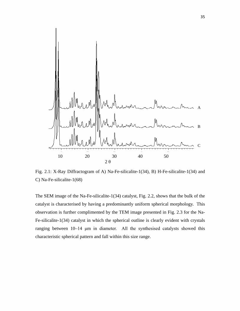
The powder XRD diffractograms of all the catalysts show the ZSM-5 pattern, (Fig. 2.1).
The intensity of the peaks confirmed that the catalysts are crystalline in nature and no Fe
haematite phase lines at 38.7 and 41.6° 2θ values [23] are observed.
Page 50
35
Fig. 2.1: X-Ray Diffractogram of A) Na-Fe-silicalite-1(34), B) H-Fe-silicalite-1(34) and
C) Na-Fe-silicalite-1(68)
The SEM image of the Na-Fe-silicalite-1(34) catalyst, Fig. 2.2, shows that the bulk of the
catalyst is characterised by having a predominantly uniform spherical morphology. This
observation is further complimented by the TEM image presented in Fig. 2.3 for the Na-
Fe-silicalite-1(34) catalyst in which the spherical outline is clearly evident with crystals
ranging between 10–14 μm in diameter. All the synthesised catalysts showed this
characteristic spherical pattern and fall within this size range.
A B C
10 20 30 40 50 2 θ
Page 51
36
Fig. 2.2: SEM image of Na-Fe-silicalite-
1(34)
Fig. 2.3: TEM image of Na-Fe-
silicalite-1(34)
In order to study the effects of varying the Si/Fe ratio on catalytic performance, the
amount of iron was varied during the synthesis to yield catalysts containing 2.01 and
1.15 wt% Fe, as obtained by XRF analysis. Hence, Si/Fe molar ratios of 34 and 68 were
obtained as shown in Table 2.1.
The BET surface measurements (Table 2.2) were found to range between 314 and
365 m2/g, with the high Si/Fe ratio catalysts observed to also exhibit higher BET surface
areas. Hydrogen-TPR results are also shown in Table 2.2 for which a single peak was
observed for all the catalysts. An equal amount of hydrogen (H2/Fe molar ratio = 0.4)
was required for the reduction of Fe in both the Na-Fe-silicalite-1(34) and the H-Fe-
Silicalite-1(34) catalysts, except that a lower temperature of 809 °C was required for the
former as compared to a 807 °C reduction temperature for the latter.
1μm 5 µm
Page 52
37
Table 2.1: FTIR and iron content analyses
Catalysts FT-IR XRF ICP-OES
(cm-1) (wt%) Si/Fe molar ratio
Na-Fe-silicalite-1(34) 1200, 1100, 796, 550 2.01 34
H-Fe-silicalite-1(34) 3500, 1200, 1100, 790, 548 2.01 34
Na-Fe-silicalite-1(68) 1200, 1049, 790, 538 1.15 68
In Na-Fe-silicalite-1(68), a H2/Fe molar ratio of 0.7 was required to reduce the Fe at a reduction
temperature of 778 °C. The lone peak observed for all the catalysts is associated with Fe3+
incorporated within the silicalite-1 framework. It is known that Fe3+ is reduced at temperatures
above 600 °C [24].
The NH3-TPD results show two peaks for all catalysts, one in the low temperature region
(159-194 °C) and the second peak in the relatively high temperature region (329-346 °C) as
shown in Table 2.2. The high temperature region results are associated with desorption of NH3
from the strong Brønsted and Lewis acid sites, while the low temperature region is associated
with the desorption of NH3 from the weak Brønsted and Lewis acid sites [25]. The H-Fe-
silicalite-1 has higher acidity as shown in Table 2.2 due to the presence of H atoms.
Table 2.2: Surface measurements
Catalysts Acidity
mmol/m2
(x 10-3)
BET H2-TPR NH3-TPD
M2/g
H2/Fe
molar ratio Tm, °C
Total
mmol/g Tm, °C
Na-Fe-silicalite-1(34) 1.08 343 0.4 809.3 0.37 193.6, 345.6
H-Fe-silicalite-1(34) 1.19 314 0.4 806.5 0.37 186.1, 335.2
Na-Fe-silicalite-1(68) 0.74 365 0.7 777.9 0.27 158.8, 329.2
2.3.2 Catalyst testing
With the synthesised catalysts fully characterised, catalysts Na-Fe-silicalite-1(34), H-Fe-
silicalite-1(34) and Na-Fe-silicalite-1(68) were tested for activity in the conversion of n-octane to
Page 53
38
oxygenates using H2O2 as oxidant. The ratio of n-octane to H2O2 was kept at 3:1 to limit
possible over oxidation. These catalysts were chosen to investigate the effect of varying the
cation in the zeolite and the effects of Si/Fe ratio towards the selectivity to terminal oxygenate
products. Data showing the overall conversion of octane (Fig. 2.4) to oxygenates shows a
gradual increase in conversion with time that is temperature dependent. The highest conversion
of 18 % was obtained at a reaction temperature of 80 °C after 2 hours. The generally low
conversions may be attributed to the rate of diffusion of products from the ZSM-5 structure
channels and pores, which are believed to be the limiting factor. The Na-Fe-silicalite-1(34) was
chosen to investigate the effects of temperature on the conversion of octane at 40, 60 and 80 °C.
Since acetonitrile boils at 80 °C, this temperature was considered as the maximum temperature.
Generally the overall conversion of octane to oxygenates increases with temperature and is
directly related to reaction time. The highest conversion of 18% was observed at 80 °C after 2
hours, which then levels off with time probably due to the very low desorption rate of the
products from the catalyst pores. Conversion of reactions at the lower temperatures levelled off
after 8 hours.
Fig. 2.4: Conversion of octane to C8 oxygenates as a function of time for Na-Fe-silicalite-1(34)
Only C8 products were obtained, namely octanol and octanones. The octanone(s)/octanol(s) ratio
results using the Na-Fe-silicalite-1(34) catalyst (Table 2.3) showed that at 40 °C the reaction
produced more octanols during the first hour of reaction (1.3 ratio). However, after six hours of
reaction, more octanones were produced, most probably due to further oxidation of the octanols.
Page 54
39
This suggests that the octanols are primary products and they are further oxidised to octanones
over time. This is further supported by the observation that octanal and 2-octanone were
produced when 1-octanol and 2-octanol were oxidised under identical conditions. At reaction
temperatures of 60 and 80 °C, octanones production was dominant throughout. However, less
octanones were obtained at 80 °C (1.4) than 60 °C reaction temperature, likely, due to the H2O2
decomposition at 80 °C which might be slightly higher than the decomposition of H2O2 at 60 °C
Table 2.3: Octanone(s)/octanol(s) ratio using Na-Fe-silicalite-1(34) at different temperatures
octanone(s):octanol(s)
Time (Hours) 40 °C 60 °C 80 °C
1 1.3 1.5 1.2 2 1.3 1.7 1.3 4 1.3 1.7 1.3 6 1.4 1.7 1.3 8 1.4 1.7 1.4
Comparing the selectivity to terminal products (Figs. 2.5 A-Fig. 2.5 C); the reaction at 40 °C
showed a better selectivity of 30% to terminal products, while the reactions at 60 and 80 °C
gave selectivities of 25% and 24% respectively. Octanal was the dominant product in these
reactions and was observed to increase with time for the reactions conducted at 40 and 60 °C.
The conversion is known to increase with increasing temperature and it is faster at higher
temperature than at lower temperate.
Since conversion was highest at 80 °C, this temperature was used to conduct further tests to
establish the scope of the catalytic process for the H-Fe-silicalite-1(34) and Na-Fe-silicalite-
1(68) catalysts. The conversion and selectivities of the catalysts were compared as shown in
Table 2.4. It was observed that the Na-Fe-silicalite-1(68) showed better selectivity (28%) to
terminal products compared to Na-Fe-silicalite-1(34) at a conversion of 13.7%. The H-Fe-
silicalite-1(34) showed 26% selectivity to terminal products at a conversion of 19.8%. The
conversion and the selectivity to terminal products of H-Fe-silicalite-1(34) were thus found to be
higher than those over Na-Fe-silicalite-1(34) (Table 2.4). The difference in activities can be
Page 55
40
attributed to the different atomic sizes of H and Na which can influence the pore size.
Fig. 2.5 : Selectivity to terminal products using Na-Fe-silicalite-1(34) at A: 40 °C, B: 60 °C and
C: 80 °C
The conversion of H2O2 over these Fe-silicalite-1 systems was found to be between 21-24 %,
corresponding to H2O2 efficiency of between 98-98.9%.
Table 2.4: Selectivity to terminal products, conversion and octanone(s)/octanol(s) ratio
Catalysts Selectivity (%)
Conversion (%) octanone(s)/octanol(s) ratio
Na-Fe-silicalite-1(34) 24 18 1.4 H-Fe-silicalite-1(34) 26 19.8 1.5 Na-Fe-silicalite-1(68) 28 13.7 1.3
Rection conditions: catalyst = 0.2 g, octane/H2O2 = 2.9 (molar ratio), acetonitrile (13 ml), reaction time = 8 hours at 80 °C Percentage deviation = 1.5% Octanones(s) = octanone(s) + octanal
A B
C
Page 56
41
When the relative concentration of H2O2 was increased by decreasing the octane/H2O2 ratio to
1:4 (Table 2.5) and using similar reaction conditions as before only a marginal increase in
conversion was observed, with the highest increase of 2.2% recorded for Na-Fe-silicalite-1(68).
Due to an increase in the relative amount of oxidant a significant change in
octanone(s)/octanol(s) ratio was observed, with higher amounts of octanones observed at the
higher H2O2 concentration used, as shown in Table 2.5, for all the catalysts. The highest relative
increase in octanones was for Na-Fe-silicalite-1(34). These results suggest again that the catalyst
first produces octanols and then octanones. To confirmed this, 1-octanol and 2-octanol were
oxidised under similar conditions and 6-8% conversions of 1-octanol to octanal and 2-4%
conversions of 2-octanol to 2-octanone were observed at 80 °C over 2 hours. However, when
radical scavengers like TEMPO (2, 2, 6, 6-tetramethylpiperidine 1-oxyl) and DPPH 1-diphenyl-
2-picrylhydrazyl) were used in conjunction with Na-Fe-silicalite-1(34), the selectivity to terminal
products improved by only 1% at the conversion of 17.8%. This suggests that there is only a
minor contribution to the OH radicals reaction outside of the silicalite-1 channel.
Table 2.5: Selectivity to terminal products, conversion and octanone(s)/octanol(s) using high
H2O2 concentration
Catalyst Selectivity
(%) Conversion
(%) octonone(s):octanol(s) ratio Na-Fe-silicalite-1(34) 24.1 19.2 2.2 H-Fe-silicalite-1(34) 26 19.9 1.7 Na-Fe-silicalite-1(68) 27 15.5 1.6
Rection conditions: catalyst = 0.2 g, octane/H2O2 =1.4 (molar ratio), acetonitrile (13 ml), reaction time = 8 hours at 80 °C Percentage deviation = 1.4% Octanone(s) =octanone(s) + octanal
Fig. 2.6 shows the reaction products distribution over the Na-Fe-silicalite-1(34) catalyst, with
octanal, 2-octanol and 2-octanone obtained in 19.8 %, 19.4 and 18.9 % selectivities. All other
products had selectivities lower than 15%. The H-Fe-silicalite-1(34) and Na-Fe-silicalite-1(68)
materials exibited a similar trend of product selectivity. No cracking products were observed for
any catalysts under any of the conditions employed.
Page 57
42
Fig. 2.6: Products distribution over Na-Fe-silicalite-1(34)
The catalyst Na-Fe-silicalite-1(34) was used to investigate catalyst stability at the optimum
temperature of 80 °C. Three cycles were conducted using the same catalyst. No change in
ZSM-5 structure was observed for the used catalyst as confirmed by XRD, FT-IR and SEM
techniques. It was observed that the catalyst maintained its conversion (18%) with no change in
product distribution, implying that the Fe-silicalite-1 is efficiently recyclable.
Furthermore, a leaching test was performed at 60 °C using Na-Fe-silicalite-1(34). The solution
was clear after filtering off the catalyst after 1 hour of reaction (hot filtration). The solution was
stirred a further 7 hours at this temperature and there was no further conversion observed. These
findings suggests that there was no leaching of Fe into the solution and that the reactions are
completely heterogeneous.
2.3.3 Oxidation of n-octane in the presence of cyclohexane
Cyclohexane was added to the reaction mixture in order to create secondary carbon competition
between the internal carbons in octane and C2 in cyclohexane. This was done with the aim of
lowering the C2 selectivity in n-octane which should result in increasing the C1 selectivity in n-
octane. Indeed, Na-Fe-silicalite-1(34) showed good selectivity of 46.5% to terminal products at
Page 58
43
room temperature. However, because both octane and cyclohexane were believed to be able to
access the channel and the cavities of the ZSM-5 structure, the cyclohexane was found to be the
preferred oxidised substrate by a factor of 300:1 to n-octane. Similar results were also obtained
at 80 ºC with the factor of cyclohexane oxidation being increased to 400:1. The limitation of this
reaction was found to be the conversion of n-octane, which was less than 1%. The amount of
H2O2 was then increased to 0.4, 0.8 and 1 mL in attempts to increase the conversion of n-octane.
Conversion of cyclohexane was found to increase with the increase in the amount H2O2, while
the conversion of n-octane remained the same.
2.4. Conclusions
Analysis using XRD and TPR showed that only one species of iron, in the form of Fe3+ was
present in all the synthesised catalysts. In catalytic reactions with n-octane and H2O2, a direct
correlation was established between temperature and conversion with the highest conversion of
18% observed at 80 °C. However, the correlation between catalyst selectivity and temperature
was an inverse relationship, with the highest selectivity of 30% to terminal products achieved at
40 °C. The results reveal a 4% improvement in selectivity to terminal products by changing the
Si/Fe ratio from 34 to 68. Addition of cyclohexane in the feed improves terminal selectivity at
the expense of octane conversion, while using H2O2 at concentrations below stoichiometric give
high H2O2 efficiencies (98-99%). Evidence implies that the oxidation reaction, most likely was a
free radical pathway, takes place almost exclusively within the Fe-silicalites channels.
Incorporation of Fe within the zeolite framework thus yields selective catalysts for the mild
oxidation of n-octane to octanols, octanones and octanal with good selectivities to terminal
products, especially octanal.
Acknowledgements
We thank c*change, the NRF, THRIP, Süd-Chemie and the University of KwaZulu-Natal for
support.
Page 59
44
References
1. Kumar, A., Mishra, G. S., J. Mol. Catal. A, 201 (2003) 179.
2. Crabtree, R. H., J. Chem. Soc. Dalton Trans. (2001) 2951.
3. Kirillova, M. V., Kozlov, Y. N., Shul'pina, L. S., Lyakin, O. Y., Kirillov, A. M., Talsi, E.
P., Pombeiro, A. J. L., Shul'pin, G. B., J. Catal., 268 (2009) 26.
4. Mac Leod, T. C. O., Kirillova, M. V., Pombeiro, A. J. L., Schiavon, M. A., Assis, M. D.,
Appl. Catal. A, 372 (2010) 191.
5. Periana, R. A., Mironov, O., Taube, D., Bhalla, G., Jones, C. J., Science, 301 (2003) 814.
6. Periana, R. A., Bhalla, G., Tenn, W. J., Young, K. J. H., Liu, X. Y., Mironov, O., Jones, C.
J., Ziatdinov, V. R., J. Mol. Catal. A, 220 (2004) 7.
7. Pillay, B., Mathebula, M. R., Friedrich, H. B., Appl. Catal. A, 361 (2009) 57.
8. Bonon, A. J., Mandelli, D., Kholdeeva, O. A. Barmatova, M. V., Kozlov, Y. N., Shul'pin,
G. B., Appl. Catal. A, 365 (2009) 96.
9. Ratnasamy, P., Srinivas, D., Catalay Tod., 141 (2009) 3.
10. Anand, R., Hamdy, M. S., Gkourgkoulas, P., Maschmeyer, T., Jansen, J. C., Hanefeld, U.,
Catal. Today, 117 (2006) 279.
11. Mansuy, D., Pure and Appl. Chem., 59 (1987) 759.
12. Mansuy, D., Pure and Appl. Chem., 62 (1990) 741.
13. Montanari, F., Pure and Appl. Chem., 66 (1994) 1519.
14. Glieder A, Arnold F. H, Nat. Biotechnol. 20 (2002) 1135.
15. Zhang, B. Z., Moden, B., Dakka, J., Santiesteban, J. G., Iglesia, E., J. Catal., 245 (2007)
316.
16. Herron, N., New J. Chem., 13 (1989) 761.
17. Glieder, A., Farinas, E. T., Arnold, F. H, Nature Biotechnology 20 (2002) 1135.
18. Thomas J. M, Raja R, Sankar G, Bell R. G, Acc. Chem. Res., 34 (2001) 191.
19. Moden B, Zhan B, Dakka J, Santiesteban J. G, Iglesia E, J Phys. Chem. C, 111 (2007)
1402.
20. Fejes, P., Kiricsi, I., Lazar, K., Marsi, I., Rockenbauer, A., Korecz, L., Nagy, J. B., Aiello,
R., Testa, F., Appl. Catal. A, 242 (2003) 247.
21. Fejes, P., Nagy, J. B., Halasz, J., Oszko, A, Appl. Catal. A, 175 (1998) 89.
Page 60
45
22. Gaag, V.d., ZSM-5 Type Zeolites: Synthesis and Use in Gas Phase Reaction with
Ammonia, Technische Universiteit, Delft, 1987.
23. Michalkiewicz, B., Appl. Catal. A, 277 (2004) 147.
24. Long, R. Q., Yang, R. T., J. Catal., 194 (2000) 80.
25. Ngobeni, M. W., Carley, A. F., Scurrell, M. S., Nicolaides, C. R., J. Mol. Catal. A, 305
(2009) 40.
Page 61
46
Chapter three Evaluation of silanization of Fe-silicalite-1, Na-Fe-ZSM-5 and
solvent concentration on the oxidation of n-octane to C8 oxygenates
Abstract
The synthesis of Na-Fe-silicalite-1(41), Na-Fe-silicalite-1(80), Na-Fe-silicalite-1(128), Na-Fe-
ZSM-5(66) and Na-Fe-ZSM-5(114) was conducted using the isomorphic substitution method.
The numbers in brackets represents the Si/Fe molar ratio and Sil represent silanization. These
catalysts were further modified by the process of silanization to yield Na-Fe-Silicalite-1(41:Sil),
Na-Fe-silicalite-1(80:Sil), Na-Fe-silicalite-1(128:Sil), Na-Fe-ZSM-5(66:Sil), and Na-Fe-ZSM-
:Sil), 5(114:Sil). The XRD analyses show that only the ZSM-5 phase was present in all the
catalysts. These catalysts were tested in the oxidation of n-octane in MeCN using H2O2 as an
oxidant. It was found that the selectivity to terminal products increased with increasing the
volume of MeCN. Thus e.g. terminal C8 selectivities could be improved from 17 to 27% using
the Na-Fe-silicalite-1(80) catalyst by increasing the volume of a solvent. Furthermore, Na-Fe-
silicalite-1(41) and Na-Fe-silicalite-1(41:Sil) showed selectivity of 20.2 and 20.7% to terminal
products. The Na-Fe-silicalite-1(80), Na-Fe-silicalite-1(80:Sil), Na-Fe-silicalite-1(128), Na-Fe-
silicalite-1(128:Sil) show terminal selectivities of 28.1, 14.3, 17.6 and 12.3% respectively. In
contrast Na-Fe-ZSM-5(66), Na-Fe-ZSM-5(114), Na-Fe-ZSM-5(66:Sil), and Na-Fe-ZSM-
5(114:Sil) show terminal selectivities of 24.5, 25.7, 21.3 and 27.3% respectively. Results also
showed that the Na-Fe-ZSM-5 catalyst has better selectivity to terminal products than Na-Fe-
silicalite-1.
Keywords: n-Octane; Oxidation; Iron; Zeolite; Silanization; Octanol; Octanone; Octanal
3.1. Introduction
Paraffins are one of the most common chemical materials on earth. However, they have very
limited applications in their natural form. They need to be converted and functionalised into a
Page 62
47
more useful material like oxygenates. Linear oxygenates have many applications in
pharmaceutical and chemical industries [1]. Therefore it is of interest to convert paraffins to
oxygenates. n-Octane was chosen for this study, since a large number of low to medium chain
paraffins are produced [2].
The inorganic structures of zeolites are widely used as matrices to incorporate a metal of interest.
This is done in order to use the zeolite material to provide shape selectivity as to mimic an
enzymatic environment. Zeolites are inorganic materials composed of aluminium and silica.
They are crystalline in nature with channels and cavities of different sizes depending on the type.
One of the special properties of these materials is the possibility of substituting Al with metals
like Fe, Co, Mn etc. into the framework of the zeolite [3]. However, the substitution of these
metals may lead to uncontrolled and undesired reactions because of the substituted metals on the
external surface of the material [4]. Therefore, there is sometimes a need to inertise the external
surface in order to control the shape selectivity that is provided by zeolite materials. Silanization
is one of the common approaches that is used to achieve this purpose [5-8]. It has been reported
that modification of the zeolite pore opening also occurs during the application of the silanization
process. This is due to deposition of silica on the entrance of the channel resulting in reduced
pore entrance sizes [9,10].
In this study, we report the synthesis of Na-Fe-silicalite-1 and Na-Fe-ZSM-5 with different Si/Fe
ratios, followed by silanization of these materials in their original Na-form using chemical liquid
deposition and tetraethoxysilane (TEOS) in hexane as a silanizing agent. It has been reported
that TEOS is a suitable silanizing agent for ZSM-5 systems because of its bulkiness (≈ 0.96 nm
in size) and the use of hexane resulted in more effective silanization compared to other solvents
[11].
3.2. Experimental
3.2.1 Catalyst synthesis
Materials: All purchased materials were used as supplied: colloidal silica Ludox 40 (Sigma-
Page 63
48
Aldrich), sodium silicate (Sigma-Aldrich), sodium hydroxide (Merck), tetrapropylammonium
bromide (TPA, Merck), iron(III) nitrate nonahydrate (Aldrich), perchloric acid 70% (Merck),
sodium chloride (Associated Chemical Enterprises), hydrochloric acid (Associated Chemical
Enterprises), hydroxylamine (Merck), ammonium hydroxide (Merck), Sc-zeolite (Süd Chemie),
potassium hydroxide (Merck), acetonitrile (Sigma-Aldrich), n-octane (Fluka), hydrogen
peroxide (Associated Chemical Enterprises), and hydrofluoric acid (Riedel-de Haën).
The catalyst material, Na-Fe-silicalite-1, was synthesised using the solid gel method [12] in the
following procedure: 0.8 g of iron nitrate was dissolved in 100 mL of double distilled water,
which was acidified by three drops of perchloric acid in a 500 mL Teflon beaker to get a clear
solution, followed by further addition of 3.5 mL perchloric acid (solution 1). In a second 500 mL
Teflon beaker, 11.5 mL of sodium silicate solution was added to 141 mL of deionized water
(solution 2). Both solutions were kept in a refrigerator overnight. While still cold, solution 2 was
added dropwise into solution 1 under vigorous stirring until pH 4.5 (using pH paper). Then
14.8 mL of colloidal silica was added into the remainder of solution 2 then this was added to
solution 1. To the slurry that formed was added 2 g sodium chloride, 6.7 g TPA and 0.2 g Sc-
zeolite seed. The pH of the resultant creamy slurry was 10.5. The slurry was transferred into a
Teflon-lined autoclave and allowed to crystallize in a Parr reactor at 160 oC for 24 hours without
agitation. After crystallization, the solids were filtered, washed with hot water and dried at
110 oC from which Na-Fe-silicalite-1(41) was obtained. The procedure was the same used in the
synthesis of Na-Fe-silicalite-1(80) and Na-Fe-silicalite-1(128) except that different amounts of
iron nitrate were used. Furthermore, the synthesis of ZSM-5 with Al and Fe added during the
synthesis was also performed to get Na-Fe-ZSM-5. The similar procedure as mentioned above
was followed except that solution 1 now contained appropriate amount of Al(NO3)3 and
Fe(NO3)3. Masses of 0.8 and 0.4 g of Al(NO3)3 were used to yield Na-Fe-ZSM-5(66) and Na-
Fe-ZSM-5(114) respectively while kept the mass of Fe(NO3)3 at 0.8 g for both synthesis. The
catalysts were calcined under N2 and then air at 550 °C [13].
Furthermore, materials were modified in their Na form by the process of silanization to
deactivate the external surface of zeolites. A mass of 2.5 g of parent Na-Fe-silicalite-1 or Na-Fe-
ZSM-5 was stirred for 21 hours in 4 wt% tetraethoxysilane (TEOS) diluted in 96 mL hexane at
Page 64
49
room temperature. After the sample was stirred for 24 hours, it was filtered, dried and calcined
under air at 550 οC to yield Na-Fe-silicalite-1(41:Sil), Na-Fe-silicalite-5(80:Sil), Na-Fe-silicalite-
1(128:Sil), Na-Fe-ZSM-5(66:Sil) and Na-Fe-ZSM-5(114:Sil), respectively. Note: Sil = Silanized.
3.2.2 Characterisation
Fourier Transform-Infrared (FT-IR) spectroscopy data was obtained within the range of
4000-400 cm-1 using a Nicolet 400 D spectrophotometer. Powder X-Ray Diffraction (XRD) was
performed using a Philips PW 1730/10 diffractometer, using Co Kα radiation, equipped with a
long line focus operating with amperage of 20 mA and voltage of 40 kV. Data was collected in
the range of 2 to 90° (2θ). Scanning Electron Microscope (SEM) data was obtained using a
Philips XL30 ESEM at 20 kV operating at a low vacuum mode of 1 Torr. Transmission Electron
Microscope (TEM) images were obtained from a JEOL JEM 1010. Inductively Coupled Plasma-
Optical Emission Spectroscopy (ICP-OES) data was collected on a Perkin Elmer (Optima 5300
DV) instrument. Samples were digested in hydroflouric acid and analysed in triplicate. The
X-Ray Fluorescence (XRF) Spectroscopy was performed on a PW 1404 X-Ray Fluorescence
instrument equipped with a flow counter detector. Brunauer-Emmet-Teller (BET) surface area
measurements were obtained using a Micromeritics Gemini instrument. The Hydrogen
Temperature Programmed Reduction (H2-TPR) and Ammonia Temperature Programmed
Desorption (NH3-TPD) were performed using a Micromeritics Autochem II chemisorption
analyzer equipped with a TCD detector. The H2-TPR data was obtained between 40 and 950 °C
(10 °C min-1) in a flow of 5% (v/v) at 15 mL min-1. The NH3-TPD analysis was collected in the
temperature range 40 to 700 °C at a constant heating rate of 5 °C min-1 after preheating the
sample to 500 °C for 2 hours under a flow of helium, then cooled to 40 °C. The nitrogen
adsorption data was collected using a Mictromeritics Tristar instrument.
3.2.3 Catalyst testing
All reactions were performed under nitrogen. In a typical test run, a desired amount of
acetonitrile was added a two-neck round bottom flask (100 mL) fitted with a stopper and a
condensor. This was followed by the sequential addition of 7.01 mmol of n-octane, 3 mL H2O2
Page 65
50
(30 wt%) and 0.2 g catalyst. The reactions were conducted in 13, 50, 60, 80 and 100 mL of
acetonitrile for 8 hours at 80 °C using Na-Fe-silicalite-1(80). The products were analysed by a
Perkin Elmer Auto System GC equipped with Flame Ionisation Detector using a Pona
50 x 0.20 mm x 0.5 μm column. The residual H2O2 was determined by titrating 1 mL of the
reaction solution acidified with 6M H2SO4 with 0.1 M KMnO4. Chlorobenzene was used as an
internal standand and the carbon balance was found to be +/-98% in all cases. Each reaction was
repeated twice.
3.2.4 Oxidation of n-octane in the presence of cyclohexane
The mass of 0.1 g of catalyst, 1 mL octane, 0.5 mL cyclohexane, 0.2 mL of H2O2 (30 %) and
chlorobenzene, as an internal standard, were added to a 5 mL round bottom flask. The reaction
was conducted at room temperature and repeated at 80 ºC. The product analysis was performed
as mentioned above.
3.3. Results and Discussion
3.3.1 Catalyst characterisation
The FT-IR results (Table 3.1) of all silicalite-1 and ZSM-5 materials show peaks at around
550 cm-1 and 1200 cm-1 which are due to the ZSM-5 framework. Another peak at 796 cm-1 is
associated with Fe-O-Si of the ZSM-5 backbone [14] . The peak observed at 1100 cm-1 is a result
of Si-O stretching [14].
The power XRD results showed that all materials have the ZSM-5 pattern. Examples are shown
in Fig 3.1. The diffractogram of the materials show that no distortion of the structure occurred
after the silanization modification processs, as the pattern remained the same (Fig. 3.1 A vs B).
Also no haematite phase, which shows peaks at 38.7 and 41.6° 2θ values, were observed, which
suggest that the crystalline materials are purely of the ZSM-5 phase [15].
Page 66
51
Table 3.1: FT-IR results of the catalysts
Catalysts FT-IR
(cm-1)
Na-Fe-silicalite-1(41) 1200, 1100, 791, 550
Na-Fe-silicalite-1(41:Sil) 1200, 1100, 790, 548
Na-Fe-silicalite-1(80) 1200, 1100, 797, 551
Na-Fe-silicalite-1(80:Sil) 1200, 1100, 795, 549
Na-Fe-silicalite-1(128) 1200, 1100, 793, 550
Na-Fe-silicalite-1(128:Sil) 1200, 1100, 790, 550
Na-Fe-ZSM-5(66) 1203, 1101, 790, 539
Na-Fe-ZSM-5(66:Sil) 1200, 1100, 792, 550
Na-Fe-ZSM-5(114) 1201, 1100, 795, 543
Na-Fe-ZSM-5(114:Sil) 1200, 1085, 791, 550
Fig. 3.1: Diffractograms of A) Na-Fe-silicalite-1(41), B) Na-Fe-silicalite-1(41:Sil) and C) Na-Fe-
ZSM-5(66)
C B A
10 20 30 40 50 60 2 θ
Page 67
52
Fig. 3.2: A) SEM image of Na-Fe-silicalite-1(41), B) SEM image of Na-Fe-silicalite-1(41:Sil) C)
TEM image of Na-Fe-silicalite-1(41),and D) TEM image of Na-Fe-silicalite-1(41:Sil)
The SEM results of Na-Fe-silicalite-1(41) and Na-Fe-silicalite-5(41:Sil) show that there is no
significant change in morphology of the catalysts (Fig. 3.2). The modification of Na-Fe-silicalite-
1(41) to Na-Fe-silicalite-1(41:Sil) through silica deposition by silanization thus does not affect
the morphology. Shown catalysts reveal a spherical shape which was also confirmed by the TEM
images in Fig. 3.2, furthermore, catalysts size range between 10-15 μm in diameter. This was
found to be similar for all the other catalysts prepared.
The surface area (Table 3.2) results reveal that the BET surface area is increasing with
decreasing iron content in the ZSM-5 system. It can also be observed that the surface area of the
silanised catalyst is slightly higher than for the unsilanised catalyst. The silanization modified the
outer surface of the catalyst and increased the Si/Fe ratio as more Si atoms deposited on the
surface, as confirmed by ICP results.
A B
D C
5 μm 5 μm
300 nm 300 nm
Page 68
53
Table 3.2: Surface properties and ICP results
Catalysts
BET
m2/g
Pore
Vol ume
cm3/g
ICP (Si/Fe) Molar
ratio
Na-Fe-silicalite-1-5(41) 311.9 0.17 41
Na-Fe-silicalite-1(41:Sil) 315.7 0.18 44
Na-Fe-silicalte-1(80) 319.2 0.19 80
Na-Fe-silicalte-1(80:Sil) 320.2 0.19 89
Na-Fe-silicalite-1(128) 336.8 0.20 128
Na-Fe-silicalite-1(128:Sil) 362.2 0.21 131
Na-Fe-ZSM-5(114) 343.1 0.19 114
Na-Fe-ZSM-5(114:Sil) 345.9 0.19 116
Na-Fe-ZSM-5(66) 293.3 0.16 66
Na-Fe-ZSM-5(66:Sil) 295.2 0.17 68
This modification thus results in changes in surface area. There was no significant change
observed on the pore volumes of the catalysts as the Si/Fe ratio increases. Also after
modification, there is no noticeable change in pore volume between silanized and unsilanized
catalysts. These results suggest that the silica deposition did not affect the pores of the ZSM-5
structure.
The H2-TPR results (Table 3.3) reveal that there is no significant change in hydrogen volume
taken up by the samples and all the catalysts showed one peak in the temperature range 764-797
ºC due to Fe3+ . Furthermore, all catalysts show two peaks in the NH3-TPD results. The low
temperature peak (179-197 ºC) is due to weak acid sites while the high temperature peak (351-
366 ºC) is due to strong acid sites of the catalyst. The nitrogen adsorption results show
hysteresis loops in the isotherm curves (Fig. 3.3). It is reported that the presence of a hysteresis
loop indicates defects within the zeolite structure. These defects influence the surface properties
of the zeolites. It has been established that these defects occur with ZSM-5 synthesised using
alkaline conditions and can influence the catalytic behaviour [16]. The defects affect the pore
sizes and shape selectivity of the zeolite and hence the selectivity could be affected
Page 69
54
Table 3.3: H2-TPR and NH3-TPD results
Catalysts H2-TPR NH3-TPD
H2/Fe molar ratio
Tm, °C
Total mmol/g Tm, °C
Na-Fe-silicalite-1(41) 0.29 788 0.33 189, 355 Na-Fe-silicalite-1(41:Sil) 0.32 769 0.35 191, 361 Na-Fe-silicalite-1(80) 0.29 789 0.34 188, 359 Na-Fe-silicalite-1(80:Sil) 0.31 785 0.33 178, 366 Na-Fe-silicalite-1(128) 0.28 781 0.31 185, 351 Na-Fe-silicalite-1(128:Sil) 0.29 777 0.32 185, 365 Na-Fe-ZSM-5(114) 0.25 791 0.34 194, 358 Na-Fe-ZSM-5(114:Sil) 0.27 766 0.32 191, 355 Na-Fe-ZSM-5(66) 0.28 769 0.32 195, 365 Na-Fe-ZSM-5(66:Sil) 0.29 764 0.34 197, 351
Fig. 3.3: Isotherm curve of Na-Fe-silicalite-1(41)
3.3.2 Catalytic testing
In the initial catalytic experiment the effect of reactant concentration was investigated and Na-
Fe-silicalite-1(80) was chosen as catalyst for this purpose. For all catalysts, only C8 products,
namely octanones, octanols and octanal were observed. The results in Fig. 3.4 show that when
the volume of acetonitrile was increased from 13 to 60 mL the selectivity to terminal products
increased from 16.9 to 23% with no significant change in conversion after 8 hours of reaction
Page 70
55
time. The highest selectivity to terminal products of 28.1% was achieved using a solvent volume
of 80 mL with a very slightly lower conversion of 2.8%. Results in Table 3.4 shows that the
octanone(s)/octanol(s) ratio increases as the volume of solvent is increased. It can be said that
the oxidation reaction pathway does not change upon dilution. The oxidation pathway is believed
to be that the octanols are primary products which are further oxidised to form octanones. The
concentration of n-octane decreases as the volume of solvent increases which could be resulting
in flattening of the n-octane concentrations due to high molecules of solvent around the n-octane
molecule. This could result in having the n-octane approaching the active site with the primary
carbon and hence activation of carbon 1 is favored.
Fig. 3.4: Conversion and selectivity to terminal product at different volumes of acetonitrile using
Na-Fe-silicalite-1(80) at 80 °C for 8 hours with H2O2 as an oxidant
Table 3.4 : Effect of the solvent volume on octanone(s)/octanol(s) ratio Vol. of MeCN (mL) octanone(s):octanol(s) ratio
13 (61.77 mg/mL) 1.1 50 (16.06 mg/mL) 1.3 60 (13.38 mg/mL) 1.4 80 (10.04 mg/mL) 1.5 100 (8.03 mg/mL) 1.8
Values in brackets represent n-octane concentration as the volume changes
The evaluation of the effect of various solvent quantities showed that a volume of 80 mL (10.04
mg/mL) was optimal volume, which showed best terminal selectivity and therefore all the
catalysts were tested using this volume of solvent (concentration in terms of n-octane). The
results (Table 3.5) show that the conversion decreases with increasing Si/Fe ratio or decreasing
Page 71
56
iron content, as it decreases from 8.8 to 2.8 and then 1.6% for Na-Fe-silicalite-1(41), Na-Fe-
silicalite-1(80) and Na-Fe-silicalite-1(128) respectively. The catalytic activity can be influenced
by the Si/Fe ratio, since the Si/Fe or Si/Al ratio controls the zeolites paraffin affinity and acidity
of zeolite can have influence on activity at higher temperatures
Table 3.5: Conversion of n-octane and selectivity to terminal products
Catalysts Conversion Selectivity to terminal
products
Na-Fe-silicalite-1(41) 8.8 20.2
Na-Fe-silicalite-1(41:Sil) 8.3 19.1
Na-Fe-silicalite-1(80) 2.8 28.1
Na-Fe-silicalite-1(80:Sil) 3.1 14.3
Na-Fe-silicalite-1(128) 1.6 17.6
Na-Fe-silicalite-1(128:Sil) 1.3 12.3
Na-Fe-ZSM-5(66) 6.3 24.5
Na-Fe-ZSM-5(66:Sil) 10.3 25.7
Na-Fe-ZSM-5(114) 1.7 20.7
Na-Fe-ZSM-5(114:Sil) 4.3 27.3
A similar trend was also observed using the silanized catalysts, as 8.3, 3.1 and 1.3% conversion
were obtained for Na-Fe-silicalite-1(41:Sil), Na-Fe-silicalite-1(80:Sil) and Na-Fe-silicalite-
1(128:Sil) respectively. The ZSM-5 material containing Al showed a conversion of 6.3 and 1.7%
for Na-Fe-ZSM-5(66) and Na-Fe-ZSM-5(114) respectively. The highest conversion of 10.3%
was observed for Na-Fe-ZSM-5(66:Sil). This conversion was found to be higher than that of Na-
Fe-ZSM-5(41), and it can be due to the amphoteric nature of Al.
There were no trends observed in the selectivity to terminal products with increasing Si/Fe ratio
of the unsilanized catalysts as selectivities of 20.2, 28.1 and 17.6% were observed for Na-Fe-
silicalite-1(41), Na-Fe-silicalite-1(80) and Na-Fe-silicalite-1(128) respectively. However, for the
silanized catalysts, the selectivity to terminal products was found to decrease with increasing
Si/Fe ratio as follows 20.7, 14.3 and 12.3% for Na-Fe-silicalite-1(41:Sil), Na-Fe-silicalite-
Page 72
57
1(80:Sil) and Na-Fe-silicalite-1(128:Sil) respectively. This trend was also observed with ZSM-5
containing Al, where selectivities of 24.5 and 21.3% were obtained for Na-Fe-ZSM-5(66) and
Na-Fe-ZSM-5(114) respectively. The silanised catalysts of ZSM-5, containing Al, showed
selectivities of 25.7 and 27.3% for Na-Fe-ZSM-5(66:Sil) and Na-Fe-ZSM-5(114:Sil)
respectively. These results were found to be different from those of Fe-Silicalite-1, without Al,
as they show a decrease in selectivity with increasing Si/Fe ratio. It was observed that
silanization of Fe-Silicalite-1 does not improve selectivity to terminal products as the unsilanized
catalysts showed better selectivity than the silanized catalysts. The ZSM-5 materials, containing
Al, were found to show improved selectivity marginally after silanization as the selectivity
increased from 24.5 to 25.7% for Na- Fe-ZSM-5(66:Sil) and from 21.3 to 27.3% for Na-Fe-
ZSM-5(114:Sil).
The effect of silanization on product distribution was not significant when Na-Fe-silicalite-1(41)
and Na-Fe-silicalite-1(41:Sil) were compared as shown in Fig. 3.5. The most noticeable change
was for 1-octanol which increased by 4% when a silanised catalyst was used. However, when the
Na-Fe-ZSM-5(114) and Na-Fe-ZSM-5(114:Sil) catalysts were compared, as shown in Fig. 3.6,
3-octanone and octanal selectivities increased by 11 and 9% respectively when the Na-Fe-ZSM-
5(114:Sil) catalyst was used.
Fig. 3.5: Products distribution over (A) Na-Fe-silicalite-1(41) and (B) Na-Fe-silicalite-1(41:Sil)
Page 73
58
Fig. 3.6: Products distribution over (A) Na-Fe-ZSM-5(114) and (B) Na-Fe-ZSM-5(114:Sil)
3.3.3 Oxidation of n-octane in the presence of cyclohexane
The secondary carbon of the cyclohexane will compete with secondary carbon in n-octane and
that competition can result in increasing the C1 activation in n-octane. Therefore, the oxidation
of n-octane in the presence of cyclohexane was conducted. The Na-Fe-silicalite-1(41), Na-Fe-
silicalite-1(41:Sil), Na-Fe-ZSM-5(66) and Na-Fe-ZSM-5(66:Sil) catalysts showed good
selectivities of 48, 47.3, 55, 57.5 % to terminal products at room temperature. The conversion
and selectivity to terminal products did not change when the temperature was increased to 80 ºC.
This trend was observed with all catalysts studied here, with cyclohexane being the most
favoured substrate with the oxidation factor of more than 300. In all the reactions conducted in
the presence of cyclohexane the conversion of n-octane was found to be less then 1% , even after
increasing the ratio of H2O2/octane to 0.8, 1.2 and 1.8, with no significant change in
octanone(s)/octanol(s) ratio observed.
3.4. Conclusion
The XRD results showed that only the ZSM-5 phase was present in all the Fe-silicalite-1 and Fe-
ZSM-5 catalysts even after silanization. Furthermore, the increase in Si/Fe ratio from the ICP
Page 74
59
results confirmed that the silanization process was successful. All catalysts were effective in the
selective oxidation of n-octane to C8 oxygenates. The amount of solvent used influenced the
selectivity to terminal products, with more dilute solutions being more selective. The catalysts
with Al showed a better selectivity to terminal products after silanization compared to those
without Al. Addition of cyclohexane did significantly improved terminal selectivity, but at the
expense of n-octane conversion.
Acknowledgements
We thank c*change, the NRF, THRIP, Süd-Chemie and the University of KwaZulu-Natal for
support.
References
1. Prieto, G., Concepción, P., Martínez, A., Mendoza, E., J. Catal., 280 (2011) 274.
2. Pillay, B., Mathebula, M. R., Friedrich, H. B., Appl. Catal. A, 361 (2009) 57.
3. Ban, T., Kondoh, S., Ohya, Y.; Takahashi, Y., Phys. Chem. Chem. Phys., 1 (1999) 5745.
4. Bauer, F., Chen, W. H., Bilz, E., Freyer, A., Sauerland, V., Liu, S. B., J. Catal., 251
(2007) 258.
5. O' Connor, C.T, Möller K.P., Manstein, H., CATTECH, 5 (2001) 182.
6. Bhat, Y. S., Das, J., Rao, K. V., Halgeri, A. B., J. Catal. 159 (1996) 368.
7. Kim, J.H., Ishida, A., Okajima, M., Niwa, M., J. Catal. 161 (1996) 387.
8. Röger, H. P., Krämer, M., Möller, K. P., O'Connor, C. T., Micropor. Mesopor. Mater., 21
(1998) 607.
9. Bhat, Y. S., Das, J., Halgeri, A. B., Appl.Catal.A, 122 (1995) 161.
10. Cejka, J., Filková, N., Wichterlová, B., Eder-Mirth, G., Lercher, J. A., Zeolites 17 (1996)
265.
11. Bauer, F., Chen, W.H., Ernst, H., Huang, S.J., Freyer, A., Liu, S.B., Micropor. Mesopor.
Mater., 72 (2004) 81.
12. Fejes, P., Kiricsi, I., Lazar, K., Marsi, I., Rockenbauer, A., Korecz, L., Nagy, J.B., Aiello,
R., Testa, F., Appl. Catal. A, 242 (2003) 247.
13. Fejes, P., Nagy, J.B., Halasz, J., Oszko, A, Appl. Catal. A, 175 (1998) 89.
Page 75
60
14. Gaag, V.d., ZSM-5 Type Zeolites: Synthesis and Use in Gas Phase Reaction with
Ammonia, Technische Universiteit, Delft, 1987.
15. Michalkiewicz, B., Appl. Catal. A, 277 (2004) 147.
16. Axon, S.A., Klinowski, J., Appl. Catal. A, 81 (1992) 27
Page 76
61
Chapter four A study of Fe(III)TPPCl encapsulated in zeolite NaY and
Fe(III)NaY in the oxidation of n-octane, cyclohexane, 1-octene and
4-octene Abstract The Fe(III)TPPCl (Fe(III) tetraphenylporphyrin chloride) complex was immobilised using the
encapsulation method in order to entrap the complex inside the faujasite NaY zeolite to obtain
FeTPP-NaY. This was achieved by adding the FeTPP as a template during the synthesis of NaY.
The ICP results show that a 0.3 wt % loading of Fe was achieved and the XRD confirmed the
faujasite Y structure. Further to this, a Fe-NaY zeolite was synthesized for the purpose of
comparing it with FeTPP-NaY. The synthesized FeTPP-NaY and Fe-NaY were tested in the
oxidation of n-octane, 1-octene, 4-octene and cyclohexane to oxygenates in the liquid phase
using acetonitrile as a solvent, H2O2 and tert-butyl hydroperoxide in water as oxidants at 80 °C.
Conversions of n-octane of 1.8 and 2.9% and selectivities to terminal products of 13 and 8.8%
were achieved using FeTPP-NaY and Fe-NaY, respectively. Conversions of 1.4 and 1.8% were
achieved for 1-octene and 4-octene, respectively. A higher conversion of 18% for cyclohexane
was observed. These results show that cyclohexane is most reactive under these conditions and
that the NaY matrix is not suitable for selective linear paraffin oxidation. Furthermore, leaching
of Fe from the Fe-NaY was observed, even though the faujasite NaY structure was maintained as
confirmed by XRD, while for FeTPP-NaY, the leaching of Fe was not observed.
Keywords: faujasite NaY; encapsulation; metallopophyrins; oxidation; octane; cyclohexane; 1-
octene; 4-octene
4.1. Introduction
Paraffins are highly abundant substances and they have a unique chemical behaviour. They tend
to burn to completion to form CO2 and water and they are also very inert [1]. This inert
Page 77
62
behaviour is due to the strong C-H bonds with the terminal C-H bonds being the strongest [2].
Non-functionalized paraffins have a very limited application in chemical, industrial and
academic fields [3]. Functionalizing paraffins to more valuable products is still a challenge,
particularly since this should occur under mild conditions. Many types of catalysts have been
investigated in the oxidation of paraffins. Porphyrins have a strong resemblance to enzymes,
hence they are utilized to mimic these [4]. They are commonly used under mild conditions using
environmental friendly oxidants such as oxygen and peroxide compounds [5-11]. Porphyrins are
known to produce good catalytic activities in homogenous reactions with separation being a
main drawback [12]. Immobilisation of porphyrins into a matrix like zeolites has been adopted
over the years. Methods of encapsulation, like the solid gel method have been reported to be
efficient in heterogenising the porphyrins [13,14]. This approach not only provides the
immobility of the porphyrin but it also improves the selectivity, depending on the nature of the
metal and the reaction conditions [15-22]. The uses of matrices like faujasite NaX and NaY are
based on the nature of their structures. Faujasite zeolites have 3-D structures with a pore width
of 7.4 Å and a cavity of 12 Å diameters [23]. These structures allow the porphyrin to remain
within their cavity and prevent it from leaching [15].
Many catalytic oxidations are accompanied by side reactions, such as cracking, isomerisation
and cyclisation, particularly in heterogeneous catalysis [24]. The oxidation of paraffins to desired
products has been an ongoing study in the field of catalysis. The primary goal is to achieve high
selectivity to the desired product. Studies have shown that this can be achieved to a degree,
depending on the reaction conditions and the nature of the catalyst. Thus oxidation of paraffins
using air over AlPO, containing metals like Co or Mn, was reported to give good selectivity to
terminal products [25]. Thomas et al. reported 34 % selectivity to terminal products at 9.5%
conversion in the oxidation of n-hexane using Co-AlPO-18 and O2 as an oxidant in the liquid
phase [26, 27]. The oxidation of cyclohexane using molecular oxygen and meso-
tetraarylporphyrin iron(III)-hydroxo complexes was reported to favour the production of
cyclohexanone without a solvent. The mixture of dichloromethane/cyclohexane, gave
cyclohexanol as the major product [28]. It has also been reported that porphyrins are active in
the photocatalytic oxidation of paraffins using O2 as co-oxidant [29-31].
Page 78
63
The selection of the type of inorganic matrix depends on the nature of reaction that is going to be
conducted. In this study, the focus is on the use of faujasite NaY as a matrix to encapsulate
FeTPP (iron tetraphenylporphyrin). We report on a comparison of the selectivities to terminal
products of the free FeTPP, Fe-NaY and FeTPP-NaY in the oxidation of n-octane to oxygenates
in the liquid phase using H2O2 and TBHP (tert-butyl hydroperoxide) as oxidants. Furthermore,
the oxidation of 1-octene, 4-octene and cyclohexane was also conducted to investigate the effect
of the faujasite (NaY) matrix.
4.2 Experimental
4.2.1 Materials
All the chemicals and the solvents used were commercially obtained (Sigma, Aldrich, Fluka and
Merck). The GC standards that were used and acetonitrile were of high purity. The acetonitrile
solvent was purged with nitrogen before any catalytic testing to remove oxygen.
4.2.2 Synthesis of free base H2TPP
The synthesis of free base H2TPP was done according to the method described by Adler [32].
Equimolar amounts of AR grade (Analytical Reagent grade) pyrrole and benzaldehyde were
refluxed for 30 minutes in propionic acid. After reaction, the mixture was cooled and washed
with methanol to get purple crystals (H2TPP).
4.2.3 Synthesis of FeTPP
The insertion of iron into the free base H2TPP was achieved by refluxing H2TPP with excess
iron(III)chloride in 45 mL of dimethylformamide for 4 hours. This mixture was cooled in an ice
bath for 2 hours, followed by the addition of 45 mL of cold water, which result in the formation
of a precipitate [32]. The precipitate was filtered, washed with water and dried at 110 °C in an
oven.
Page 79
64
4.2.4 Synthesis of Fe-NaY and FeTPP-NaY
The synthesis of Fe-NaY was achieved by dissolving 0.4 g of Fe(NO3)3, 9.8 g of sodium
hydroxide and 5 g of isopropyl aluminium in 37 mL of double distilled water over 2 hours. This
was followed by addition of 29 ml of 30% colloidal silica Ludox 40 (40 wt% silica suspension in
water) dropwise resulting in a white gel. The mixture was stirred for 24 hours at room
temperature, followed by aging at 60 °C in a Parr reactor for 72 hours [33]. The similar
procedure was followed, without the addition of Fe(NO3)3, where 0.5 g of the metalloporphyrin
was added into the formed gel to produce FeTPP-NaY. The resultant catalyst was filtered,
washed with double distilled water and purified using soxhlet extraction with chloroform, as
FeTPP dissolves in chloroform, thus removing any remaining complex of the FeTPP on the
external surface. The FeTPP inside the NaY is believed to be trapped because of its bulkiness,
therefore only external FeTPP will be removed during the extraction.
4.2.5 Characterization of the catalysts
The FTIR spectra were collected on a Perkin Elmer ATR spectrometer Spectrum 100 FTIR
resolution of 4 cm-1 and speed of 0.2 cm-1 per second. The UV-Vis analysis was performed using
a Perkin Elmer Precisely Lambda 35 UV/Vis spectrometer and putting chloroform solution at the
sample in a 1 cm quartz cuvette. The 1H NMR data were collected on a Bruker Advance 400
MHz spectrometer. The elemental analysis was performed on a LECO CHNS-932 instrument.
The X-ray diffraction was carried out using Bruker AXS D8 Advance diffractometer using Cu
Kα radiation. The data was collected between 5 to 60º (2θ) at the rate of 1° min -1 with a 0.02
scanning step size. TGA/DTG analysis was conducted on a AMS SDT Q 600 V2.09 Build 20
instrument using air to purge at 100 mL min-1. The analyses were collected from room
temperature to 1000 °C at 10 °C min-1. All the samples were coated with gold before SEM
analysis in order to improve the contrast. A Philips Xl30 ESEM at 20 kV spot 5 operating at a
low vacuum mode of 1 torr with a Lurge Field Detector was used for these analyses. The ICP-
OES (Inductively Coupled Plasma Optical Emission Spectroscopy) analysis was conducted to
determine the weight percent for Fe in the Fe-TPP-NaY and Fe-NaY samples. All ICP-OES
analysis were done in triplicate. A Perken Elmer Precisely (Optima 5300 DV) instrument was
Page 80
65
used for analysis. The sample preparation involved dissolving approximately 0.5 g of sample in
HF.
4.2.6 Catalytic testing
The oxidation of n-octane, 1-octene, 4-octene, or cyclohexane, respectively using the synthesized
catalyst was conducted at 80 °C. The reactions were conducted in a 50 mL two-neck round
bottom flask. An amount of 7.10 mmoles of substrate was introduced first, followed by the
addition of 0.21 g of catalyst and 13 mL degassed acetonitrile. The oxidant, 12 mmol H2O2 (30
wt% in H2O) or TBHP (70 wt% in H2O), was added slowly thereafter. The reaction was
performed under N2. The reaction was stopped after 8 hours since monitoring the products by
GC showed that the conversion did not increase after 8 hours. The products were analyzed using
a GC coupled with a FID detector using a Pona column (50 m x 0.15 mm x 0.42 µm). All
reactions were performed a minimum of two times and were consistent. Dichlorobenzene was
used as an internal standard to quantify the reaction products and conversions. All reactions
were repeated 2 times and the conversion was found to be consistent
4.3 Results and discussion
4.3.1 Characterization of FeTPP
In the FTIR (Fig. 4.1), the porphyrin H2TPP shows a peak around 3316 cm-1, due to the N-H
vibrations [34]. However, this peak is not observed in FeTPP. The absence of this peak is
associated with the insertion of Fe within the porphyrin ring. This result proves that Fe is
complexed by porphyrin. The porphyrin ring vibrations are also observed at about 1000 cm-1.
The peaks above 2000 cm-1 are observed in FeTPP at low intensity due to the presence of Fe.
Page 81
66
4000.0 3600 3200 2800 2400 2000 1800 1600 1400 1200 1000 800 600 380.019.1
25
30
35
40
45
50
55
60
65
70
75
80
85
90
95
100.0
cm-1
%T
994.57
3316.24
Fig.4. 1: FTIR of A) H2TPP and B) FeTPP
The NMR spectrum of H2TPP (Fig. 4.2) shows a peak at -2.75 ppm which is due to N-H. In the
aromatic region, the following peaks at 8.89 ppm, assigned to pyrrole protons, 8.35 ppm for
ortho protons and the meta and para position protons appear at 7.88 ppm [35]. These results
confirmed the synthesis of H2TPP. Furthermore, the NMR spectrum of Fe-TPP showed no peaks
which indirectly implies that Fe was complexed by the porphyrin since Fe is paramagnetic, and
thus NMR inactive.
A
B
Page 82
67
Fig.4. 2: 1H NMR of H2TPP
The UV-Vis results shows the spectra of H2TPP (Fig. 4.3 A) and of FeTPP (Fig. 4.3B) with a
Soret band at 419 nm which corresponds to the literature value of 418 [36], and the difference in
the FeTPP and H2TPP spectra can be attributed to the coordination of Fe [34].
Fig. 4.3: UV-Vis spectra of H2TPP (A) and FeTPP (B) in chloroform solution recorded at room
temperature (H2TPP = 2.4 x 10⁻⁶ M and FeTPP = 2.4 x 10⁻⁶ M)
NH
N
NH N
HNHa
Ha
Hb
HcHd
Ha
Hc/Hd
Hb
Page 83
68
Table 4.1: Elemental analysis of H2TPP and FeTPP
%
Elements C H N Fe
Observed 84.92 5.19 9.14 -
Literature [34] H2TPP 84.01 4.9 8.96 -
Observed 78.08 4.97 7.98 8.98
Literature [34] FeTPP 77.90 4.41 8.23 8.96
Elemental analysis (Table 4.1) results for both H2TPP and FeTPP were found to be in agreement
with literature [34]. The ICP-OES result showed 0.3 and 1.0 wt% Fe in FeTPP-NaY and Fe-NaY
respectively.
4.3.2 Characterization of Fe-NaY and FeTPP-NaY
The powder XRD results of NaY, Fe-NaY, fresh FeTPP-NaY and used FeTPP-NaY show the
pattern expected of a faujasite (Fig. 4.4). A difference in peak intensity was observed between
NaY and Fe-NaY at 10º θ as shown in Fig. 4.4 A and B. This difference can be attributed to the
presence of Fe in the structure. In Fig. 4.4 C, a peak at 8º of 2θ is observed for FeTPP-NaY and
is due to the presence of the FeTPP in the faujasite [37, 38]. This result demonstrates that the
crystalline structure of the faujasite-NaY was preserved after the encapsulation of Fe-TPP. Peaks
at 15, 20, 27 and 28 2-theta were observed for all materials but with different intensity due to the
different interaction between host (faujasite-NaY) and the guest molecule. The morphology of
these materials was also found to be the same, as shown in Fig. 4.5 (SEM). Furthermore, there is
no evidence of adsorbed FeTPP on the external surface of the faujasite NaY. The images of the
Fe-TPP-NaY are the same as those of NaY and show no crystals of Fe-TPP-Cl on the external
surface of NaY. This further suggests that the Fe-TPP is encapsulated in the NaY cages.
Page 84
69
Lin
(Cou
nts)
0
1000
2000
3000
4000
5000
6000
7000
8000
2-Theta - Scale5 10 20 30 40 50 60
Fig. 4.4: Powder XRD patterns of (A) NaY, (B) Fe-NaY, (C) Fresh FeTPP-NaY and (D)
recycled FeTPP-NaY
D C B A
5 10 15 20 25 30 35 40 45 50 55 2 θ
Page 85
70
Fig. 4.5: SEM images of (A) NaY, (B) Fe-NaY, (C) FeTPP-NaY and (D) recycled FeTPP-NaY
A TGA-DTA investigation was carried out to determine the thermal decomposition patterns of
the molecules. The TGA-DTA curve of NaY in Fig. 4.6 (A) shows a peak at around 200 °C
which is due to water loss. The mass loss between 200 °C and 400 °C in Fig. 4.6 (B) can be
attributed to water loss and the decomposition of FeTPP. This correlates with the decomposition
of FeTPP in FeTPP-NaY in Fig. 4.6 (C) that occurs around 600 °C. The shift of decomposition
temperature from 400 °C to 600 °C is due to the environment around the organic moiety as it is
inside the NaY matrix
A B
C
1 μm 200 nm
200 nm
D
2 μm
Page 86
71
Fig. 4.6: DSC-TGA curves of (A) NaY, (B) FeTPP and (C) FeTPP-NaY
4.3.3 Catalytic testing
There was no conversion observed when the oxidation of n-octane was attempted without the
addition of the catalysts as shown in Table 4.2. Results also demonstrate that there is no
contribution from NaY to the oxidation on n-octane (Table 4.2). The highest conversion of
n-octane was observed using Fe-TPP under conditions of 2 molar ratios of H2O2/octane (19%).
This was followed by FeNaY with a conversion of 2.6%, while the FeTPP-NaY showed the
lowest conversion of 1.8%. A similar trend was observed under the conditions of 1 molar ratio of
H2O2/octane and also when TBHP was used as an oxidant. The higher conversion over FeTPP
can be attributed to the fact that the iron content in FeTPP was found to be 1.7 times higher than
the iron content in FeTPP-NaY used for the oxidation reaction. There was, however, no
conversion of octane when 0.008 g of FeTPP was used, which is equivalent to the 0.3 % Fe
90
200 400 600 800 Temperature (°C)
DSC-TGA
C
0
20
40 60
80 100
120
0 200 400 600 800 Temperature (°C)
DSC-TGA
70 75 80
85
90
95
100
0 200 400 600 800 Temperature (°C)
DSC-TGA
A
Wei
ght (
%)
Wei
ght (
%)
B
100 95 90 85 80 75 80
Wei
ght (
%)
Page 87
72
found in FeTPP-NaY. Thus, the fact that the low Fe content is active when encapsulated within
the NaY showed that encapsulation not only heterogenised the catalyst, but also improved
activity.
Table 4.2: Conversion of n-octane over different catalysts
Catalyst AConversion (%) BConversion (%) CConversion (%)
BlankD 0 0 0
NaY 0 0 0
FeTPPE 0 0 0
FeTPPF 19.0 12.0 5.1
Fe-NaY 2.6 2.9 3.1
Fe-NaY (recycled) 0.7 - -
FeTPP-NaY 1.8 1.0 1.8
FeTPP-NaY(dark)G 1.9 - 1.7
FeTPP-NaY (recycled) 1.4 - - AReaction conditions: 0.2 g of catalysts (0.003 x 0.21 = 0.00063 g of iron), mmoles H2O2/octane = 2 in 13 mL
MeCN, 80 °C oil bath temperature, conversion = {[substrate (in) – substract(out)]/substract(in)}x 100, Bmmoles
H2O2/octane = 1 CTBHP/octane = 2 in 13 mL MeCN DReaction conditions: No catalyst added, mmoles H2O2/octane = 2 in 13 mL MeCN, 80 °C oil temperature EReaction conditions: 0.008 g of catalysts (FeTPP), mmoles H2O2/octane = 2 in 13 mL MeCN, 80 °C oil bath
temperature FAn amount of 0.015 g of FeTPP was added (0.0898 x 0.015 = 0.00135g of iron) GReaction conditions: 0.2 g of catalysts (0.003 x 0.21 = 0.00063 g of iron), mmoles H2O2/octane = 2 in 13 mL
MeCN, 80 °C oil bath temperature, and the reaction was performed in the dark
The study also showed different conversion between Fe-NaY and FeTPP-NaY which is believed
to be due to active site environment. The active site in FeTPP-NaY is inside the zeolite cavity
and therefore the diffusion, adsorption of octane and desorption of products effects are greater
than in Fe-NaY, where the active sites can be outside or at the entrance of the zeolite channels or
cavity. When a lower amount of H2O2 was used, 1 molar ratio of H2O2/octane, FeTPP showed a
drop in conversion from 19% to 12%, while Fe-NaY showed no significant change and FeTPP-
NaY showed a noticeable drop in conversion from 1.8 to 1%.
Page 88
73
Table 4.3 A: Product distribution using higher H2O2 concentration
Selectivity
Catalyst 1-ol 2-ol 3-ol 4-ol al 2-one 3-one 4-one
Blank 0 0 0 0 0 0 0 0
NaY 0 0 0 0 0 0 0 0
FeTPP 11.1 5.5 8.6 6.2 9.6 22.5 19.1 17.0
Fe-NaY 2.5 8.8 6.4 6.2 6.3 24.9 22.7 22.2
FeTPP-NaY 6.8 7.5 7.9 6.4 6.2 26.2 20.6 18.4
FeTPP-NaY(dark) 6.5 7.6 8.1 6.0 6.1 27.1 19.5 19.1 Mole H2O2/octane = 2, selectivity = (product/conversion)x 100
Table 4.3 B: Product distribution using lower H2O2 concentration
Selectivity
Catalyst 1-ol 2-ol 3-ol 4-ol al 2-one 3-one 4-one
Blank 0 0 0 0 0 0 0 0
NaY 0 0 0 0 0 0 0 0
FeTPP 10.8 5.7 7.5 6.3 9.6 22.8 19.4 18.1
Fe-NaY 4.1 11.4 5.9 6.2 8.2 23.3 20.7 18.1
FeTPP-NaY 6.9 11.0 6.7 6.4 7.4 20.1 16.8 22.9 Mole H2O2/octane = 1
The FeTPP showed the highest selectivity to octanones in all reactions with carbon 2 (numbered
from the terminal carbon) being the highest activated position. Table 4.3 A shows the highest
selectivity of 22.5 % to 2-octanone followed, by 3-octanone, 4-octanone, 1-octanol, octanal, 3-
octanol, 4-octanol and 2-octanol, respectively. A similar trend was observed when a lower
amount of H2O2 was used as shown in Table 4.3 B. In some cases, it was observed that when a
lower quantity of H2O2 was used, it was observed that the selectivity to octanones dropped and
the selectivity to octanols increased with the exception of 4-octanone which was high.
Page 89
74
Table 4.3 C: Products distribution using TBHP as an oxidant
Selectivity
Catalyst 1-ol 2-ol 3-ol 4-ol al 2-one 3-one 4-one
Blank 0 0 0 0 0 0 0 0
NaY 0 0 0 0 0 0 0 0
FeTPP 8.9 5.3 4.7 4.1 6.6 31.9 20.4 19.5
FeNaY 6.8 2.8 4.9 4.3 5.7 32.8 20.6 19.1
FeTPP-NaY 6.2 5.5 4.9 4.4 5.6 34.4 20.4 19.5 Mole TBHP/octane = 2
Thus secondary oxidation of the octanols to octanones was reduced, as expected. However, C2
activation continues to dominate. The conversion and product distribution was found to be same
as under normal conditions when the similar oxidation reaction was done in the dark as shown in
Table 4.3 A, implying no photo oxidation. The selectivity to octanones increased when TBHP
was used as an oxidant as shown in Table 4.3 C. However, the alcohol selectivity trend changed
as 1-octanol is followed by 2-octanol, then 3-octanol, with 4-octanol having the lowest
selectivity. This change in selectivity can be attributed to a steric effect of TBHP since it is bigger
than H2O2.
No uniform trend of product distribution was observed when Fe-NaY was used in the oxidation
of octane using H2O2 and TBHP. Three different product distribution trends were observed,
which can be due to the leaching of Fe from the NaY system into the solvent at different rates,
and it thus reacts as free Fe(III) in solution like a Fenton catalyst with no control of selectivity
achieved. The following distributions were observed: Table 3A; 2-octanone > 3-octanone > 4-
octanone > 2-octanol > 3-octanol > octanal > 4-octanol > 1-octanol, Table 4.3B; 2-octanone > 3-
octanone > 4-octanone > 2-octanol > octanal > 4-octanol > 3-octanol > 1-octanol, Table 3 C; 2-
octanone > 3-octanone > 4-octanone > 1-octanol > octanal > 3-octanol > 4-octanol > 2-octanol.
These trends are only similar to each other for the octanoness but change for the octanols.
Similarly, there was no significant change observed in the products distribution when FeTPP-
NaY was tested under similar conditions. The only noticeable change was with 2-octanol, which
Page 90
75
increased from 7.5% selectivity under higher H2O2 concentration to 11.0% when a lower H2O2
concentration was used (Table 4.3A). TBHP seems to produce more octanones.
The reaction mechanism using peroxide oxidants is believed to follow the radical reaction.
Equations 1 and 2 show the generation of radicals which react with the organic molecule
according to equation 3 to produce the product [39].
Fe3+ + H2O2 Fe2+ + HOO• + H+ (1)
Fe2+ + H2O2 Fe3+ + 2OH• (2)
OH• + R-H R-OH + H• (3)
There was no change in the position of carbon activation observed when the reactions conducted
were compared and all followed the sequence: C2 > C3 > C4 > C1. These results suggest that
there was no dramatic influence introduced by the faujasite system in terms of improving or
modifying the product selectivity. This might be due to the fact that the pore size of 7.4 Å is too
big for linear paraffins like n-octane, hence no or limited shape selectivity can be achieved.
To evaluate the effect of NaY pore size, the epoxidation of a mixture of 1-octene and 4-octene
was investigated using FeTPP-NaY. This was done to establish whether any selectivity would be
induced by the NaY matrix. An equal number of moles of 1-octene and 4-octene were reacted.
A conversion of 1.6 and 1.8% of 1-octene and 4-octene was obtained respectively. From this
reaction, only 1,2-epoxyoctane, which is the epoxidation product of 1-octene and 2,3 dipropyl
oxirane, which is the epoxidation product of 4-octene, were observed. These results suggest that
there was no preference between internal or terminal activation from NaY. Therefore, it can be
concluded that the pore sizes of the NaY zeolite are likely too large to provide shape selectivity
for linear paraffins.
It was found that FeTPP-NaY showed good activity in the activation of cyclohexane. Thus
access to the catalyst sites was not restricted. The oxidation of this substrate was performed
under similar oxidation conditions as for n-octane. The results showed 35, 38 and 27%
selectivity to cyclohexanone, cyclohexanol and hydroperoxycyclohexane respectively, at a
conversion of 18% after 8 hours reaction time.
Page 91
76
4.3.4 Recycling Fe-NaY and FeTPP-NaY
Fig. 4.7 compares the product distribution of fresh FeTPP-NaY used once for 8 hours (a) and the
recycled FeTPP-NaY that was reused for a second time for another 8 hours (b). The only
difference that was observed between the two reactions is that the recycled catalyst showed a
lower selectivity of 2.7% to 1-octanol compare to the initial 6.8 %. There was no significant drop
in conversion of the recycled catalyst (1.4% compared to 1.8%). These results suggest that the
FeTPP does not leach out into the acetonitrile. This was also confirmed by the UV-Vis spectra
where no absorbance of FeTPP was observed in the acetonitrile solution after reaction (Fig. 4.8).
The ICP results shows that the amount of Fe in Fresh FeTPP-NaY and the FeTPP-NaY recycled
are equal.
Fig. 4.7: Products distribution over (A) FeTPP-NaY (fresh) and (B) FeTPP-NaY (recycled) conditions: 0.2 g of catalysts, mmoles H2O2/octane = 2 in 13 mL MeCN, 80 °C oil temperature
A
B
Page 92
77
Fig. 4.8: MeCN solution after reaction using FeTPP-NaY (A) and FeTPP (B) in MeCN
On the other hand, there was a major drop in conversion when Fe-NaY was recycled. A
conversion of 0.7% was obtained compared to 2.6% for the fresh catalyst, though product
selectivities were similar (Fig. 4.9). This suggests that the Fe has leached out of the NaY system.
The ICP results reveal that there was a drop of Fe content in the recycled Fe-NaY and 0.8% Fe
was found in the reaction solution. This result suggested that a considerable quantity of iron was
not in the framework of the NaY, since the XRD of the recycled Fe-NaY showed that the
faujasite structure was maintained.
Fig. 4.9: Products distribution over (A) Fe-NaY (fresh) and (B) Fe-NaY (recycled) Conditions: 0.2 g of catalysts, mmoles H2O2/octane = 2 in 13 mL MeCN, 80 °C oil temperature
A B
Page 93
78
4.4. Conclusion
The synthesis of both Fe-NaY and FeTPP-NaY has been achieved as confirmed by XRD
analyses. The FeTPP-NaY is active in the oxidation of cyclohexane, 1-octene and 4-octene and,
furthermore, the FeTPP does not leach from the NaY matrix which indicates that the catalyst
works as a heterogeneous catalyst. The relative low selectivity to terminal products suggests that
the channel size is too large to induce primary activation only.
Acknowledgements
We acknowledge support from c*change, the NRF and THRIP, as well as the EM unit (UKZN
Westville campus).
References
1. Thomas, J. M., Raja, R., Sankar, G., Bell, R. G., Acc. Chem. Res. 34 (2001) 191.
2. Moden, B., Zhan, B. Z., Dakka, J., Santiesteban, J. G., Iglesia, E., J. Phys. Chem. 111
(2007) 1402.
3. Fernandes, R. R., Kirillova, M. V., da Silva, J. A. L., da Silva, J. J. R., Pombeiro, A. J. L.,
Appl. Catal. A : Gen. 353 (2009) 107.
4. Cook, B. R., Reinert, T. J., Suslick, K. S., J. Am. Chem. Soc. 108 (1986)7281.
5. Groves, J. T., J Porphyrins Phthalocyanines 4 (2000) 350.
6. Guedes, A. A., Smith, J. R. L., Nascimento, O. R., Guedes, D. F. C., Assis. M. D., J.
Braz. Chem. Soc. 16 (2005) 835.
7. Halma, M., Castro, K., Taviot-Gueho, C., Prevot, V., Forano, C., Wypych, F., Nakagaki,
S., J. Catal. 257 (2008) 233.
8. Li, Z., Xia, C. G., Xu, C. Z., Tetrahedron Lett. 44 (2003) 9229.
9. Mac Leod, T. C. O., Faria, A. L., Barros, V. P., Queiroz, M. E. C., Assis, M. D., J. Mol.
Catal A: Chem. 296 (2008) 54.
10. Pardo, E., Lloret, F., Carrasco, R., Muñoz, M. C., Temporal-Sánchez, T., Ruiz-Garcı́ a, R.,
Inorg. Chim. Acta 357 (2004) 2713.
Page 94
79
11. Rahiman, A. K., Rajesh, K., Bharathi, K. S., Sreedaran, S., Narayanan, V., Inorg Chim
Acta 362 (2009) 1491.
12. Madadi, M., Rahimi, R., Reac. Kinet. Mech. Cat. 107 (2012) 215.
13. Trytek, M., Majdan, M., Lipke, A., Fiedurek. J., J. Catal. 286 (2012) 193.
14. Trytek, M., Fiedurek, J., Lipke, A., Radzki, S., J. Sol-Gel Sci. Technol. 51: (2009) 272.
15. Balkus, K. J., Khanmamedova, A. K., Dixon, K. M., Bedioui, F., Appl. Catal. A: Gen.
143 (1996) 159.
16. Higashio, Y., Shoji,T., Appl. Catal. A : Gen. 260 (2004) 251.
17. Langhendries, G., Baron, G. V., Neys, P. E., Jacobs, P. A., Chem. Eng. Sci. 54 (1999)
3563.
18. Lindsey, J. S., Schreiman, I. C., Hsu, H. C., Kearney, P. C., Marguerettaz, A. M., J. Org.
Chem. 52 (1987) 827.
19. Nakagaki, S., Xavier, C. R., Wosniak, A. J., Mangrich, A. S., Wypych, F., Cantao, M. P.,
Denicolo, I., Kubota, L. T., Colloid Surf A Physicochem. Eng. Aspects 168 (2000) 261.
20. Radha, R. V., Radha, K.M., Kulkarni, S. J., Raghavan, K. V., Catal. Commun. 6 (2005)
531.
21. Rosa, I. L. V., Manso, C. M. C. P., Serra. O. A., Iamamoto, J. Mol. Catal. A: Chem. 160
(2000) 199.
22. Salavati-Niasari, M., Shaterian, M., Ganjali, M. R., Norouzi, P., J. Mol. Catal. A Chem.
261 (2007) 147.
23. Fujiwara, M., Xu, Q., J. Mol. Catal. A Chem. 142 (1999) 77.
24. Mishra, G. S., Kumar, A., Kinet Catal. 45 (2004) 394.
25. Dhakshinamoorthy, A., Alvaro, M., Garcia, H., Chem. Eur. J. 17 (2011) 6256.
26. Cavani, F., Catal. Today 157 (2010) 8.
27. Thomas, J. M., Hernandez-Garrido, J. C., Bell, R. G., Top. Catal 52 (2009) 1630.
28. Maldotti, A., Bartocci, C., Inorg. Chem. 35 (1996) 1126.
29. Trytek, M., Lipke, A., Eur. J. Org. Chem. 2013 (2013) 1653.
30. Trytek, M., Fiedurek, J., Biotechn. Progr. 23 (2007) 131.
31. Rosenthal, J., Luckett, D., J. Am. Chem. Soc. 128 (2006) 6546.
32. Alder, A. D., Longo, L. R., Kampas, F., Kim, J., J. Inorg. Nucl. Chem. 32 (1970) 2443.
33. Huang, Y., Wang, K., Dong, D., Li, D., Hill, M. R., Hill, A. J., Wang, H., Microporous.
Page 95
80
Mesoporous. Mater. 127 (2010) 167.
34. Salker, A. V., Gokakakar, S. D., Int. J. Phys. Science 4 (2009) 77.
35. Falvo, R. E., Mink, L. M., Marsh, D. F., J. Chem. Ed. 76 (1999) 237.
36. Costa, A. A., Ghesti, G. F., de Macedoa, J. L., Braga, V. S., Dias, J. A., Dias, S. C. L., J.
Mol. Catal. A: Chem. 282 (2008) 149.
37. Quayle, W. H., Peeters, G., De Roy, G. L., Vansant, E. F., Lunsford, J. H., Inorg. Chem. 21
(1982) 2226.
38. Quayle, W. H., Lunsford, J. H., Inorg. Chem. 21 (1982) 97.
39. Tantiwa, N., Kuntiya, A., Seesuriyachan, P., Chiang Mai J. Sci. 40 (2013) 60.
Page 96
81
Chapter five Liquid phase oxidation of n-octane to C8 oxygenates over modified
Fe-MOF-5 catalysts
Abstract
The Metal Organic Framework materials Fe4-MOF-5, Fe2-Zn2-MOF-5 and Fe0.9-Zn3.1-MOF-5
were prepared. The XRD results showed the expected pattern of MOF-5 with a very sharp peak
at a 2θ value below 10° which indicate that the material are highly crystalline. The SEM and
TEM images showed that the catalysts are cubic in shape. The synthesised Fe4-MOF-5, Fe2-Zn2-
MOF-5 and Fe0.9-Zn3.1-MOF-5 were testing in the oxidation of n-octane using H2O2 as an
oxidant in acetonitrile as solvent. Conversions of 10.5, 4.2 and 3.6% were obtained for Fe4-
MOF-5, Fe2-Zn2-MOF-5 and Fe0.9-Zn3.1-MOF-5 respectively. It was observed that primary
carbon activation increased with decreasing Fe content, as C-1 selectivities of 9.5, 12.9 and
19.8% were achieved for Fe4-MOF-5, Fe2-Zn2-MOF-5 and Fe0.9-Zn3.1-MOF-5 respectively. Only
C8 oxygenate products were observed, which include 1-octanol, 2-octanol, 3-octanol, 4-octanol,
octanal, 2-octanone, 3-octanone, 4-octanone and octanoic acid. Furthermore, these catalysts
were tested in the oxidation of cyclohexane using H2O2 in acetonitrile. Selectivities of 48.3% for
cyclohexanol, 47.1% for cyclohexanone and 4.6% for hydroperoxycyclohexane were recorded at
a conversion of 40% using Fe4-MOF-5 as a catalyst.
Keywords: n-octane; cyclohexane; MOF-5; octanol; octanone; oxidation; cyclohexanol;
cyclohexanone; hydroperoxycyclohexane
5.1. Introduction
Recently, there has been much interest in MOF (metal organic framework) materials. These types
of materials come in different shapes and types and possess unique physical and chemical
properties [1-7]. They tend to be softer that the traditional aluminosilicate zeolite materials like
Page 97
82
ZSM-5, mordenite and faujasite, hence they resemble more closely the behaviour of enzymes.
They are porous materials with 3D structures of interconnected metal and different inorganic
linkers and have a very wide range of applications, which include gas storage, catalysis etc. [8-
12].
One of the most promising MOFs is MOF-5. This type of MOF materials have been reported to
have a high potential in the catalytic field [13]. An iron copper MOF-5 has been reported in the
oxidation of xanthene using t-butylhydroperoxide and the catalyst was found to be stable and
reusable under reaction conditions [14]. In this study we now report the synthesis of Fe-MOF-5
and Fe-Zn-MOF-5 with different iron content and the testing of them in the oxidation of n-octane
and cyclohexane using H2O2 in acetonitrile.
The activation of medium chain length alkanes is becoming increasingly important as these
paraffins are major low value by-products from gas and coal to liquid plants, the number of
which is increasing [15], and paraffins can offer green routes to valuable oxygenates. Terminally
functionalised octanols are high value products and are difficult to achieve, since secondary
carbon atoms are more reactive that the primary ones. Systems reported that show high
selectivity to terminal carbon activation usually achieve this with very low conversion, typically
less than 1% [16].
5.2. Experimental
5.2.1 Materials
All the reagents and solvents used were commercially supplied (Sigma, Aldrich, Fluka and
Merck). The GC standards used and acetonitrile were of high purity. The acetonitrile was purged
with nitrogen before any catalytic testing to remove oxygen.
5.2.2 Synthesis of Fe-MOF-5
The synthesis of Fe-MOF-5 was achieved following the reported method [17] by mixing 1.2 g
Page 98
83
Fe(NO3)3 and 0.334 g terephthalic acid in 40 mL DMF under vigorous stirring followed by
addition of 2.2 mL TEA dropwise. The mixture was stirred for 2 hour when a brownish
precipitate was formed. The precipitate was filtered, washed with DMF and added to chloroform
and stood overnight. Thereafter, the precipitate was filtered and dried. The general formula of
MOF-5 is Zn4O13C24H12, and the value of metals must be kept at 4 molar values. Furthermore,
Zn was added to balance the value of metals when the amount of Fe used was less than 4. The
effect of Fe content variation on selectivity to terminal products will be evaluated. The synthesis
of Fe-Zn-MOF-5 was conducted using the above mentioned procedure with the inclusion of
Zn(NO3)2 and the appropriate amount of Fe(NO)3.
5.2.3 Catalysts characterization
Fourier Transform-Infrared (FT-IR) spectroscopy data was obtained within the range of 4000-
400 cm-1 using a Nicolet 400D spectrophotometer. Powder X-Ray Diffraction (XRD) was
performed using a Philips PW 1730/10 diffractometer, using Cu Kα radiation, equipped with a
long line focus operating with amperage of 20 mA and voltage of 40 kV. Data was collected in
the range of 2 to 50° (2θ). Inductively Coupled Plasma-Optical Emission Spectroscopy (ICP-
OES) data was collected on a PerkinElmer (Optima 5300 DV) instrument. Samples were
digested in HCl acid and the analysis were done in triplicate Scanning Electron Microscope
(SEM) data was obtained using a Philips XL30 ESEM at 20 kV operating at a low vacuum mode
of 1 Torr. Transmission Electron Microscope (TEM) images were obtained from a JEOL JEM
1010. Brunauer-Emmet-Teller (BET) surface area measurements were obtained using a
Micromeritics Gemini instrument. The catalysts were degassed overnight under nitrogen at
200 °C.
5.2.4 Catalytic testing
All the reactions were performed under nitrogen. In a typical test run, 13 mL of acetonitrile was
added into a two-neck round bottom flask (100 mL) fitted with a stopper and a condensor. The
oxidation was performed by adding a mass of 0.1 g catalyst, 1 mL cyclohexane and 1 mL H2O2
(30 wt%) as an oxidant. The products were analysed by a PerkinElmer Auto System GC
Page 99
84
equipped with Flame Ionisation Detector using a Pona 50 x 0.20 mm x 0.5 μm column. The
residual H2O2 was determined by titrating 1 mL of the reaction solution acidified with 6M H2SO4
with 0.1 M KMnO4. The carbon balance for all oxidation reactions was found to be +/- 98 %
(above 98 % of the reacted n-octane correspond to the total products formed).
5.3. Results and discussion
5.3.1 Catalyst characterisation
The FT-IR results (Table 5.1) show a peak around 1570 cm-1 which is due to carboxylate anions
in the catalyst material. The peak of the –COOH group of the terephthalic acid (linker), which
appears around 1760 - 1690 cm-1, was not observed in the Fe-MOF-5 catalyst confirming that
there is coordination between the linker and metal ion [17].
The XRD results in Fig. 5.1 show a sharp peak below 10° which indicates that the materials are
highly crystalline [18]. The diffractograms also show the MOF-5 pattern which is in agreement
with literature [18]. The SEM images in Fig. 5.2 A - C reveal that the material is cubic in shape
and crystalline, with a size range 100–300 µm. The TEM images in Fig. 5.2 D - F are in
agreement with the SEM images, again showing that the material is cubic in shape [19, 20]. The
BET surface areas (Table 5.1) of the synthesised catalysts were found to be 599, 575 and 501
m2/g for Fe4-MOF-5, Fe2-Zn2-MOF-5 and Fe0.9-Zn3.1-MOF-5 respectively, which is in agreement
with literature [21]. The difference in surface are of the catalysts can be attributed to the
precence of Zn in the catalysts, and surface area decreases with increasing Zn amount. The ICP
results confirmed the presence of Fe and Zn in all synthesised catalysts. The Fe:Zn molar values
of 2:0, 2:2 and 0.9:3.1 for -MOF-5, Fe2-Zn2-MOF-5 and Fe0.9-Zn3.1-MOF-5 respectively, were
observed.
Page 100
85
Lin (Co
unts)
0
10000
20000
30000
40000
50000
60000
70000
80000
2-Theta - Scale5 10 20 30 40 50 60
Fig. 5.1 : Powder X-Ray Diffractograms of A) Fe4-MOF-5, B) Fe2-Zn2-MOF-5 and C) Fe0.9-
Zn3.1-MOF-5
Table 5.1 :FT-IR, BET and ICP results of MOF-5 catalysts
Catalyst FTIR (cm-1) BET (m2/g) ICP (molar)
Fe Zn Fe4-MOF-5 1570 599 4 0 Fe2-Zn2-MOF-5 1569 575 2 2 Fe0.9-Zn3.1-MOF-5 1570 501 0.9 3.1
C B A
10 20 30 40 2θ
Page 101
86
Fig. 5.2: A) SEM image of A) Fe4-MOF-5, B) Fe2-Zn2-MOF-5 and C) Fe0.9-Zn3.1-MOF-5
and TEM images of D) Fe4-MOF-5, E) Fe2-Zn2-MOF-5 and F) Fe0.9-Zn3.1-MOF-5
5.3.2 Catalytic testing
Table 5.2: Oxidation of n-octane using Fe-MOF-5 catalysts
Catalysts % Fe
Conversion
%
Selectivity %
C1 C2 C3 C4
Fe4-MOF-5 1 10.5 8.9 35.1 29.5 26.5
Fe2-Zn2-MOF-5 0.5 4.2 12.9 32.9 31.5 22.7
Fe0.9-Zn3.1-MOF-5 0.2 3.6 19.8 28.8 29.6 21.8
Fe4-MOF-5a 1 10.3 9.2 35.1 29.4 26.3 Rection conditions: catalyst = 0.1 g,octane /H2O2 = 1 (molar ratio), aRecycled catalyst, acetonitrile (13 mL), reaction time = 4 hours at 80 ºC, blank rection (withouth a catalysts) showed no conversion of n-octane Conversion error range 1.7-2.4 %
A D
1 µm 1 µm
1 µm 1 µm
1 µm 1 µm
F C
B
E
Page 102
87
Table 5.3: Product distribution over Fe-MOF-5 catalysts
Catalysts Selectivity (%) 1-ol 2-ol 3-ol 4-ol al 2-one 3-one 4-one
Fe4-MOF-5, 5.5 7 9.5 7.7 3.4 28.1 20 18.8 Fe2-Zn2-MOF-5 7 7.4 10.2 7.6 5.9 25.5 21.3 15.1 Fe0.9-Zn3.1-MOF-5 10.7 7.7 9.3 7.9 9.1 21.1 20.3 13.9 Fe4-MOF-5a 5.1 6.6 9.4 8.1 4.1 28.5 20 18.2
aRecycled catalyst
Table 5.4: octanone(s):octanol(s) ratios using Fe-MOF-5 catalysts
Catalysts octanone(s):octanol(s) Fe4-MOF-5
2.4
Fe2-Zn2-MOF-5
2.1 Fe0.9-Zn3.1-MOF-5
1.8
Fe4-MOF-5a 2.4 aRecycled catalyst
The C8 oxygenates (4-octanone, 3-octanone, 2-octanone, octanal, 4-octanol, 3-octanol, 2-octanol
and 1-octanol) were the only products observed, with a small amount of octanoic acid, which
was found to be less than 1% in selectivity. Furthermore, the selectivity to octanones decreased,
and the selectivity to octanols increased with decreasing Fe content. This is likely due to fewer
catalytic sites being available for further oxidation of the octanols formed.
The oxidation results (Table 5.2) show that the conversion of n-octane increases as the Fe content
of the MOF-5 increases. Thus, Fe4-MOF-5 showed a conversion of 10.5%, while Fe2-Zn2-MOF-
5 and Fe0.9-Zn3.1-MOF-5 showed 4.2 and 3.6% of conversion respectively. The Fe4-MOF-5
catalyst shows the highest carbon activation at C2, followed by C3, C4 and lastly C1 with 35.1,
29.5, 26.5 and 8.9% selectivity respectively. When Fe2-Zn2-MOF-5 was used, a different trend
was observed. Activation at C3 showed higher selectivity compared to C2 and a trend of C3 > C2
> C4 > C1 with 32.9, 31.9, 22.7 and 12.9% selectivity, respectively, was observed. This change
can be attributed to the presence of Zn atoms in the catalyst that might be occupying the external
corners of the cube creating a specific environment for Fe atoms [22]. A change in product
distribution was further observed when Fe0.9-Zn3.1-MOF-5 was used. Here there was a very small
difference between activation of C3 and C2 as they show a selectivity of 29.6 and 28.8%
Page 103
88
respectively. Also for C4 and C1, there was no significant difference between the sites as they
show 21.8 and 19.8% selectivity respectively. The results also showed that as the Fe content
decreases, the selectivity to C1 activation increases. One of the major advantages of these
catalysts is the fact that they are recyclable which allow the interest to be mainly on selectivity.
The Fe0.9-Zn3.1-MOF-5 achieved 4% conversion at 20% selectivity to terminal products and the
unreacted n-octane can be recycled back to the reaction and more selectivity to terminal product
and be achieved.
Catalysts Fe4-MOF-5 and Fe2-Zn2-MOF-5 in Table 3 showed the following product distribution
trend: 2-octanone > 3-octanone > 4-octanone > 3-octanol > 4-octanol > 2-octanol > 1-octanol >
octanal. However, a different trend was observed when Fe0.9-Zn3.1-MOF-5 was used: 2-
octanone > 3-octanone > 4-octanone > 1-octanol > 3-octanol > octanal > 4-octanol > 2-octanol.
This change can be attributed to the low amount of Fe and high amount of Zn atoms in Fe0.9-
Zn3.1-MOF-5 which may promote Fe atoms to be situated in a more hindered environment that
promotes the C1 activation.
The octanone(s)/octanol(s) ratios showed the values of 2.4, 2.1 and 1.8 for Fe4-MOF-5, Fe2-Zn2-
MOF-5 and Fe0.9-Zn3.1-MOF-5 respectively. These results suggest that the production of
octanols is increasing as the Fe content in the catalysts decreases, likely due to fewer Fe sites,
hence reduced further reaction of the primary products, octanols, to octanones. The H2O2
conversion was found to be 69, 61 and 45% for Fe4-MOF-5, Fe2-Zn2-MOF-5 and Fe0.9-Zn3.1-
MOF-5, respectively, giving an H2O2 efficiency of 15.2, 6.9 and 7.8% for Fe4-MOF-5, Fe2-Zn2-
MOF-5 and Fe0.9-Zn3.1-MOF-5 respectively. The H2O2 efficiency thus decreases with decreasing
iron content. It is known that H2O2 react with Fe to produce radicals [23] and water. The loss of
H2O2 efficiency can be attributed to the high Fe content that react with H2O2 to produce more
water instead of products (oxygenates).
Page 104
89
Table 5.5: Oxidation of cyclohexane using Fe-MOF-5 catalysts
Catalysts
%
Fe
Conversion
%
Selectivity %
cyclohexanol cyclohexanone hydroperoxycyclohexane
Fe4-MOF-5, 1 40 48.3 47.1 4.6
Fe2-Zn2-MOF-5 0.5 36 49.8 47.0 3.2
Fe0.9-Zn3.1-MOF-5 0.2 33 51.1 45.2 3.7 Reaction conditions: catalyst = 0.1 g, H2O2 /cyclohexane 1 (molar ratio), acetonitrile (13 mL), reaction time = 4 hours at 80 ºC
The oxidation of cyclohexane over Fe-MOF-5 showed only a slight drop in conversion as the Fe
content decreases (Table 5.5). Conversions of 40, 36 and 33% were observed for Fe4-MOF-5,
Fe2-Zn2-MOF-5 and Fe0.9-Zn3.1-MOF-5 respectively, clearly showing the higher reactivity of
secondary carbon atoms. The products distribution of all catalysts was found to be similar, with
the cyclohexanol selectivity being the highest with a selectivity between 48.3–51.1%, followed
by cyclohexanone with a selectivity between 45.2–47.1% and, lastly, hydroperoxycyclohexane
with the selectivity between 3.2–4.6%. The most noticeable change in product distribution is
that the Fe0.9-Zn3.1-MOF-5 which showed slightly higher cyclohexanol selectivity of 51.1% and a
correspond lower cyclohexanone selectivity at 45.2%. This can be due to the lower number of
Fe sites, hence deeper oxidation is reduced. The selectivity to hydroperoxycyclohexane in our
results might be due to the higher temperature which resulted in over-oxidation. The H2O2
conversion was found to be 48-70% with a H2O2 efficiencies of between 57- 69%
5.3.3 Recycling and leaching test of Fe4-MOF-5
Fig. 5.3: Powder X-Ray Diffractogram of used Fe4-MOF-5
2 θ
Page 105
90
Fig. 5.4: Images A) SEM and B) TEM of used Fe4-MOF-5
The catalyst Fe4-MOF-5 was recycled to establish the stability of the catalyst. The catalyst was
used three times to establish the stability and leaching. The reaction results showed (Table 5.3)
that there was no loss of activity when the catalyst was used for the third time as the conversion
of 10.3% is close to the 10.5% conversion from the fresh catalyst Fe4-MOF-5. The product
distribution of the recycled catalyst (second and the third cycle) was found to be similar to that of
a fresh catalyst. Furthermore, XRD, SEM and TEM results showed that the recycled catalyst
still has MOF-5 phase and shows no distortion in shape. The ICP results of the reaction solution
showed that there was no Fe in the reaction solution, which suggests that the Fe did not leach
from the catalyst, and therefore the catalyst is stable.
5.4. Conclusion
The XRD results confirmed the synthesis of the Fe-MOF-5 and modified Fe-Zn-MOF-5 and the
SEM and TEM images showed that the catalyst is cubic in shape. The catalytic tests showed that
decreasing the Fe content in Fe-MOF-5 increases the activation for C1 in the oxidation of
n-octane, with a decrease in conversion. Only C8 oxygenated products were obtained with a
highest selectivity to primary oxygenates of 19.8%. All Fe-MOF-5 catalysts tested showed a
similar product distribution in the oxidation of cyclohexane. Furthermore, the catalysts are
stable, can be recycled and do not leach.
A
2 µm
B
2 µm
Page 106
91
Acknowledgements
We acknowledge support from c*change, the NRF and THRIP, as well as the EM unit (UKZN
Westville campus).
References
1. D. Farrusseng, D. Aguado, S., Pinel, C.,Angew. Chem. Int. Ed. 48 (2009) 7502.
2. Müller-Buschbaum, K.Y., Mokaddem, Y., Solid State Sci. 10 (2008) 416.
3. Spokoyny, A. M., Farha, O. K., Mulfort, K. L., Hupp, L. J., Mirkin, C. A., Inorg. Chim.
Acta.364 (2010) 266.
4. Wang, L. Zhang, T. Song, T., Li, C., Xu, J., Wang, L., Micropor. Mesopor. Mater.
155 (2012) 281.
5. Xiao, B., Hou, H., Fan, Y., Tang, M., Inorg. Chim. Acta 360 (2007) 3019.
6. Zhao, N., Li, W., Sun, C., Bian, H., Wang, H., Chang, Z., Fan, H., Solid State Sci.
14 (2012) 317.
7. Loiseau, T., Férey, G., J Fluor. Chem. 128 (2007) 413.
8. Gao, W., Xing, D., Zhou, D., Shao, M., Zhu, S., Chem. Commun. 14 (2011) 601
9. Jin, N., Seo, J., Hong, K., Chun,H., Micropor. Mesopor. Mater. 150 (2012) 32.
10. Nayak, S., Nayek, H. P., Pietzonka, C., Novitchi, G., Dehnen, S. J., J. Mol. Struct.
1004 (2011) 82.
11. Torrisi, A., Bell, R. G., Mellot-Draznieks, C., Micropor. Mesopor. Mater. 168
(2013) 225.
12. Wang, L., Song, T., Li, C., Xia, J., Wang, S., Wang, L., Xu, J., J. Solid State Chem. 190
(2012) 208.
13. Zhang, L., Hu, Y. H., Mater. Sci. Eng. B 176 (2011) 573.
14. Dhakshinamoorthy, A. M., Alvaro, M., Garcia, H., J. Catal. 267 (2009) 1.
15. Pillay, B., Mathebula, M. R., Friedrich, H. B., Appl. Catal. A 361 (2009) 57. 16. Moden, B., Zhan, B., Dakka, J., Santiesteban, J. G., Eglesia, E., Phys. Chem. C
111 (2007) 1402. 17. Phan, N. T., Le,K. A., Phan, T. D., Appl. Catal. A 382 (2010) 246. 18. Saha, D., Deng, S., Yang, Z., J. Porous. Mater. 16 (2006) 141.
19. Li, J., Cheng, S., Zhao, Q., Long, P., J. Dong, Int. J. Hydrogen Energy. 34 (
2009) 1377.
Page 107
92
20. Liu, Y., Ng, Z., Khan, E. A., Jeong, H. K., Ching, C. B., Lai, Z., Micropor.
Mesopor. Mater. 118 (2009) 296.21.
21. Dhakshinamoorthy, A., Alvaro, M., Garcia, H., Chem. Eur. J. 17 (2011) 6256.
22. Ardelea, O., Blanita, G., Mihet, M., Coldea, I., Lupu, D., Palade, P., Rev. Roum.
Chim. 56 (2011) 655.
23. C. Jiang, C., Gao, Z., Qu, H., Li, J., Wang, X., Li, P., Liu, H., J. Hazard. Mater.
250-251 (2013) 76.
Page 108
93
Chapter six Summary and Conclusion
The synthesis of Fe-Silicalite-1 (FS-1) and Fe-ZSM-5 was achieved using the isomorphic
substitution method to incorporate the Fe into the framework structure of the zeolite. The XRD
results revealed that only the ZSM-5 phase was obtained for all the synthesised catalysts even
after modification. The Na-Fe-Silicalite-1(34) shows that the conversion of n-octane was a
temperature dependent. The higher conversion of 18% was achieved at 80 ºC followed by 16
and 9% conversion at 60 and 40 ºC respectively. However, the selectivity to terminal products
was found to be an inverse relationship as the highest selectivity of 30% was observed at 40 ºC
while 25 and 24% selectivity was obtained at 60 and 80 ºC respectively. Furthermore, the results
showed that the octanone(s)/octanol(s) ratio increases with time in all three temperatures
suggesting that octanols are primary products which upon further oxidation resulted to
octanones. Only C8 oxygenate products were observed. The selectivity to terminal products
was found to be higher when the oxidation was performed in the presence of cyclohexane at the
expense of very low n-octane conversion. The XRD and SEM results showed that the catalysts
are stable. They could also be recycled and the conversion of recycled catalyst was found to be
the same as of the fresh catalyst, with the same product distribution.
The modification of catalysts using the process of silanisation was successful, as there was no
alteration of the observed ZSM-5 phase. There was no changed observed in the pore volume of
the modified catalysts by silanisation compared to the catalysts that were not silanised. The ICP
results showed higher Si/Fe ratio of silanised catalysts which suggested that the Si atom was
deposited. The selectivity to terminal products was found to be influenced by the amount of
solvent (octane concentration). The silanisation of Fe-Silicalite-1 catalysts showed no effect on
improving the conversion of n-octane and the selectivity to terminal products. However, a
significant change in conversion was observed when silanised Fe-ZSM-5 catalysts were used.
Furthermore, the selectivity to terminal products also improved by 6.6% when Na-Fe-ZSM-
5(114:Sil) compare to Na-Fe-ZSM-5(114). It was also observed that the addition of cyclohexane
improved the selectivity to terminal products, again at the expense of n-octane conversion.
Page 109
94
A study of zeolite encapsulated FeTPP was conducted. The TGA-DTA results showed that the
organic moiety (FeTPP) is inside the NaY matrix, which suggesting that the encapsulation of
FeTPP (Fe-tetraphenylporphyrin) inside the cavity of faujasite zeolite NaY was achieved to give
the FeTPP-NaY catalyst. The FeTPP-NaY was found to produce more octanones when higher
concentration of H2O2 was used. However, the selectivity to octanones dropped when low
concentration of H2O2 was used. Only C8 oxygenate products were observed in all n-octane
oxidation reactions. The FeTPP-NaY catalyst was found to be more suitable for the oxidation of
cycloparaffins like cyclohexane than linear paraffins like octane. There was no shape selectivity
observed in the oxidation of octane in acetonitrile solvent using H2O2 and TBHP as oxidants.
The product distribution from Fe-TPP-NaY was found to be similar to the product distribution
obtain from the use of Fe-TPP under similar oxidation reaction conditions.
The conventional method of synthesis was used to synthesise the Fe-MOF-5(1), Fe-Zn-MOF-
5(0.5) and Fe-Zn-MOF-5(0.2) materials. The XRD, SEM and TEM results showed that the
MOF-5 phase and cubic shape were obtained. The conversion of n-octane was found to
increased with the increasing Fe content. However, the selectivity to terminal products
decreased with the increasing Fe content. The highest selectivity of 19.8% to terminal products
was achieved using Fe-MOF-5(0.2). The oxidation of cyclohexane using H2O2 as an oxidant in
acetonitrile solvent showed that the MOF-5 phase can be used as a matrix to entrap the Fe metal
in order to use it as a heterogeneous catalyst. The XRD, SEM and TEM results showed that the
catalyst is stable and can be recycled. There was no leaching of Fe found during the oxidation
reaction.
In conclusion, this work has shown that Fe-zeolite type materials are effective in the oxidation of
n-octane in the liquid phase and that good selectivity to terminal products can be achieved.
Furthermore, the silanization of Fe-ZSM-5 improved the selectivity to terminal products.
Page 110
95
APPENDIX Supplemental information
Page 111
96
Diffractograms 97 SEM images 98 - 102 TEM images 103 - 107 Products distribution 108 Isotherm curves 109 - 114
Table of content
Page 112
97
Mdu2Lin
(Cou
nts)
0
10000
2-Theta - Scale5 10 20 30 40 50 60
Fig. A1: Diffractogram of A) Na-Fe-silicalite-1(80:Sil), B) Na-Fe-silicalite-1(128), C) Na-Fe-silicalite-1(128:Sil), D) Na-Fe-ZSM-5(114) E) Na-Fe-ZSM-5(114:Sil), F) Na-Fe-ZSM-5(66) and G) Na-Fe-ZSM-5(66:Sil)
A B C D E F G
10 20 30 40 50 2 θ
Page 113
98
Fig. A2: SEM of H-Fe-silicalite-1(41)
Fig. A3: SEM of Na-Fe-silicalite-1(68)
2 µm
2 µm
Page 114
99
Fig. A4: SEM of Na-Fe-silicalite-1(80)
Fig. A5: SEM of Na-Fe-silicalite-1(80:Sil)
2 µm
2 µm
Page 115
100
Fig. A6: SEM of Na-Fe-silicalite-1(128)
Fig. A7: SEM of Na-Fe-silicalite-1(128:Sil)
10 µm
1 µm
Page 116
101
Fig. A8: SEM of Na-Fe-ZSM-5(114)
Fig. A9: SEM of Na-Fe-ZSM-5(114:Sil)
1 µm
1 µm
Page 117
102
Fig. A10: SEM of Na-Fe-ZSM-5(66)
Fig. A11: SEM of Na-Fe-ZSM-5(66:Sil)
1 µm
2 µm
Page 118
103
Fig. A12: TEM of H-Fe-silicalite-1(41)
Fig. A13: TEM of Na-Fe-silicalite-1(68)
2 µm
2 µm
Page 119
104
Fig. A14: TEM of Na-Fe-silicalite-1(80)
Fig. A15: TEM of Na-Fe-silicalite-1(80:Sil)
2 µm
2 µm
Page 120
105
Fig. A16: TEM of Na-Fe-silicalite-1(128)
Fig. A17: TEM of Na-Fe-silicalite-1(128:Sil)
2 µm
2 µm
Page 121
106
Fig. A18: TEM of Na-Fe-ZSM-5(114)
Fig. A19: TEM of Na-Fe-ZSM-5(114:Sil)
2 µm
2 µm
Page 122
107
Fig. A20: TEM of Na-Fe-ZSM-5(66)
Fig. A21: TEM of Na-Fe-ZSM-5(66:Sil)
2 µm
2 µm
Page 123
108
Fig. A34: Products distribution over (A) Na-Fe-silicalite-1(80) and (B) Na-Fe-silicalite-1(80:Sil)
Fig. A35: Products distribution over (A) Na-Fe-silicalite-1(128) and (B) Na-Fe-silicalite-
1(128:Sil)
Fig. A36: Products distribution over (A) Na-Fe-ZSM-5(66) and (B) Na-Fe-ZSM-5(66:Sil)
Page 124
109
Fig. A37: Isotherm curve of Na-Fe-silicalite-1(34)
Fig. A38: Isotherm curve of H-Fe-silicalite-1(34)
Page 125
110
Fig. A39: Isotherm curve of Na-Fe-silicalite-1(68)
Fig. A40: Isotherm curve of Na-Fe-silicalite-1(41:Sil)
Page 126
111
Fig. A41: Isotherm curve of Na-Fe-silicalite-1(80)
Fig. A42: Isotherm curve of Na-Fe-silicalite-1(80:Sil)
Page 127
112
Fig. A43: Isotherm curve of Na-Fe-silicalite-1(128)
Fig. A44: Isotherm curve of Na-Fe-silicalite-1(128:Sil)
Page 128
113
Fig. A45: Isotherm curve of Na-Fe-ZSM-5(114)
Fig. A46: Isotherm curve of Na-Fe-ZSM-5(114:Sil)
Page 129
114
Fig. A47: Isotherm curve of Na-Fe-ZSM-5(66)
Fig. A48: Isotherm curve of Na-Fe-ZSM-5(66:Sil)