[1] Marquez, J. L., Molina, M. G., and Pacas, J. M. (2010). Dynamic modeling, simulation and control design of an advanced micro-hydro power plant for distributed generation applications. International journal of hydrogen energy, 35(11), 5772-5777.
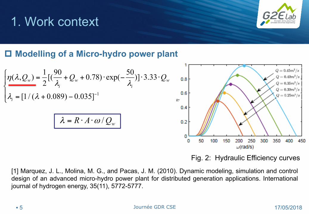
Fig. 2: Hydraulic Efficiency curves
/ wR A Qλ ω= ⋅ ⋅
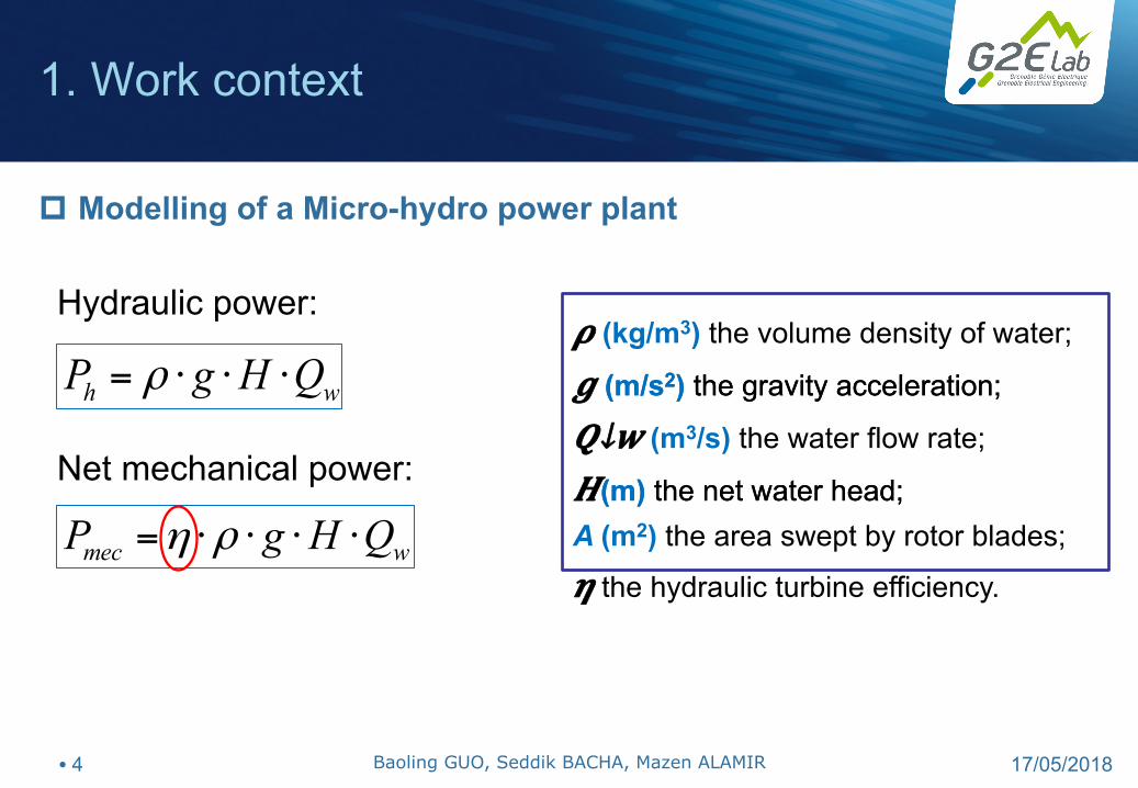
p Modelling of a Micro-hydro power plant
• 5 17/05/2018 Journée GDR CSE
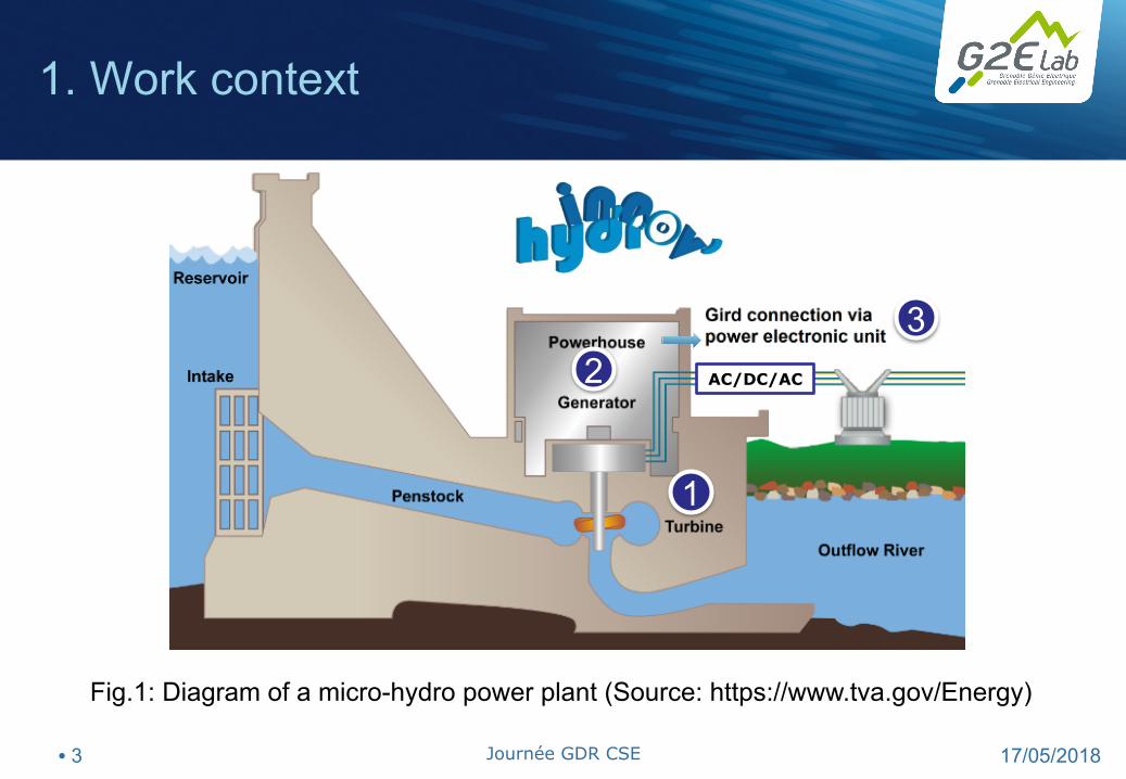
1. Work context
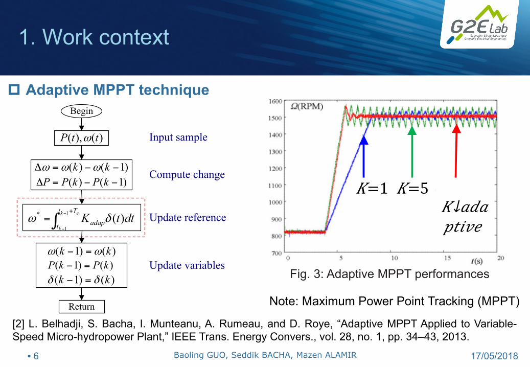
[2] L. Belhadji, S. Bacha, I. Munteanu, A. Rumeau, and D. Roye, “Adaptive MPPT Applied to Variable-Speed Micro-hydropower Plant,” IEEE Trans. Energy Convers., vol. 28, no. 1, pp. 34–43, 2013.
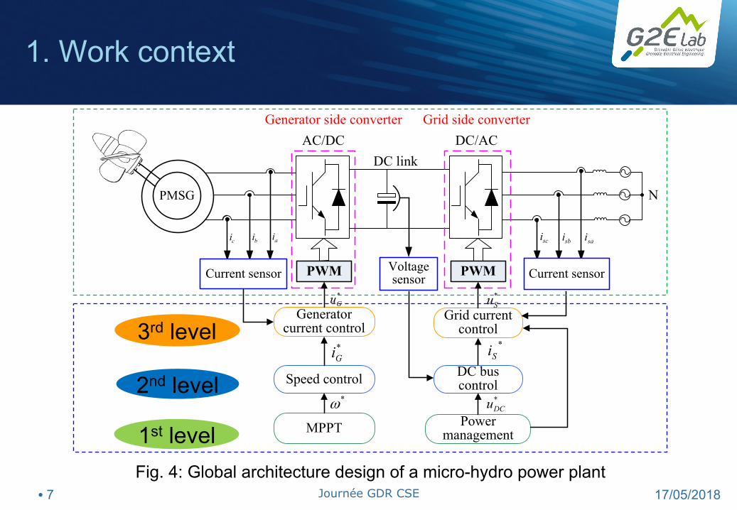
Generator side converter Grid side converterAC/DC DC/AC
Speed control DC bus control
MPPT Power management
*ω
*Gi
*Gu *
Su
*Si
*DCu
1st level
2nd level
3rd level
Fig. 4: Global architecture design of a micro-hydro power plant
1. Work context
• 7 17/05/2018 Journée GDR CSE
Content
1. Work context
2. Control context
3. ADRC based variable speed control
(Active Disturbance Rejection Control)
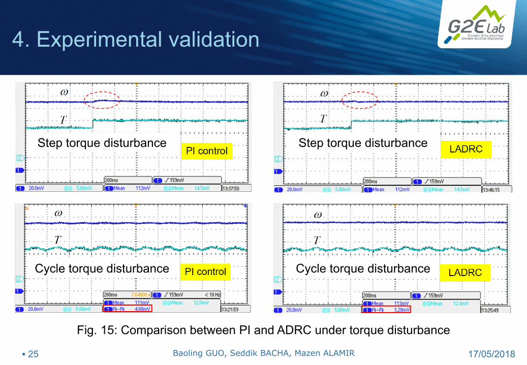
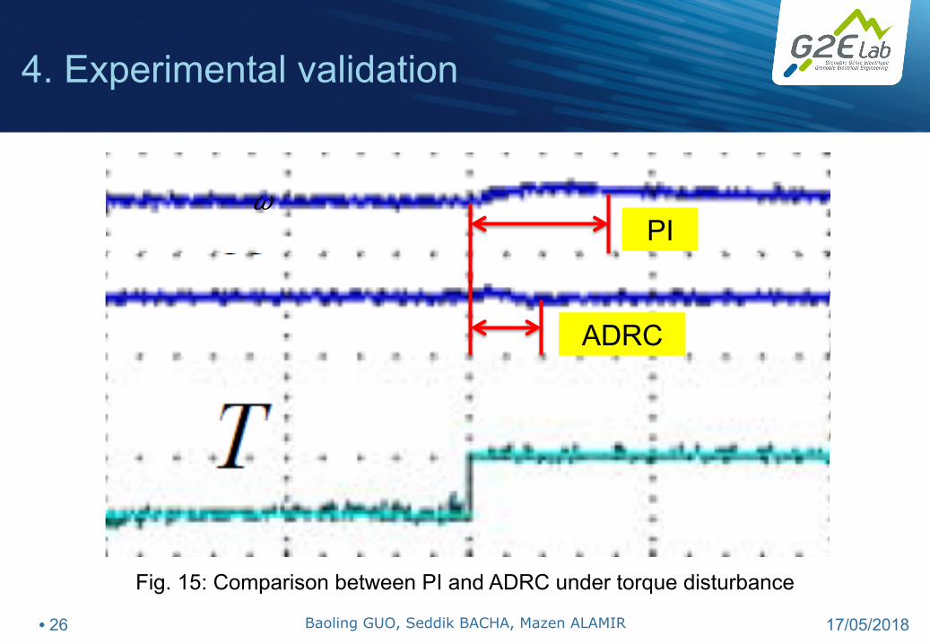
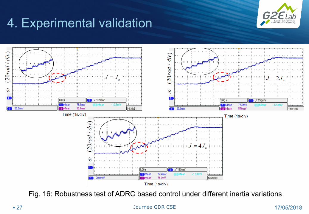
4. Experimental validation
5. Conclusions
6. Future research discussion
• 8 17/05/2018
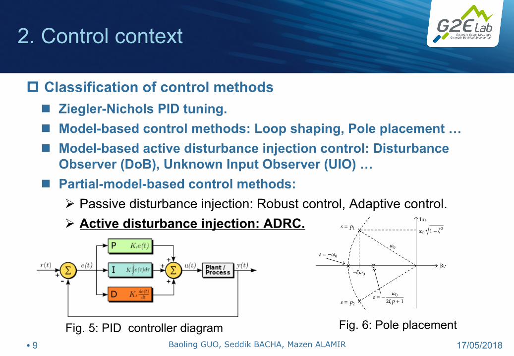
n Ziegler-Nichols PID tuning. n Model-based control methods: Loop shaping, Pole placement … n Model-based active disturbance injection control: Disturbance
Observer (DoB), Unknown Input Observer (UIO) … n Partial-model-based control methods:
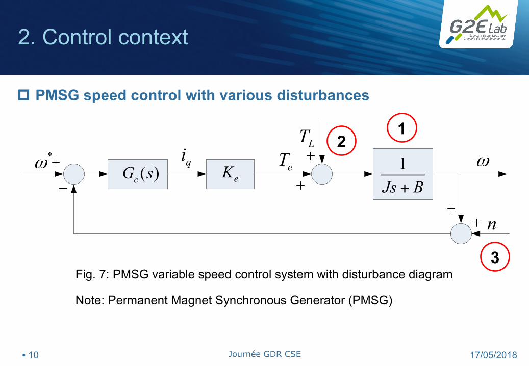
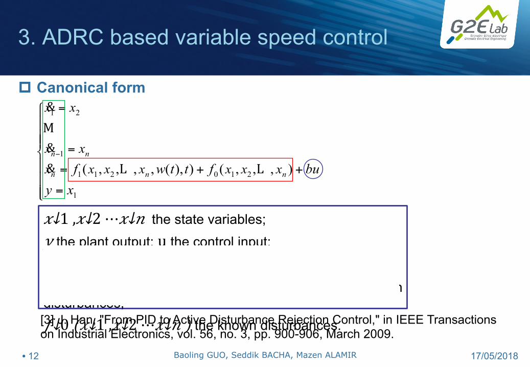
𝑥↓1 , 𝑥↓2 ⋯ 𝑥↓𝑛 the state variables; 𝑦 the plant output; u the control input; 𝑤(𝑡) the uncertain external disturbance;
𝑓↓1 ( 𝑥↓1 , 𝑥↓2 ⋯ 𝑥↓𝑛 , 𝑤(𝑡),𝑡) the unknown disturbances; 𝑓↓0 (𝑥↓1 , 𝑥↓2 ⋯ 𝑥↓𝑛 ) the known disturbances. [3] J. Han, "From PID to Active Disturbance Rejection Control," in IEEE Transactions on Industrial Electronics, vol. 56, no. 3, pp. 900-906, March 2009.
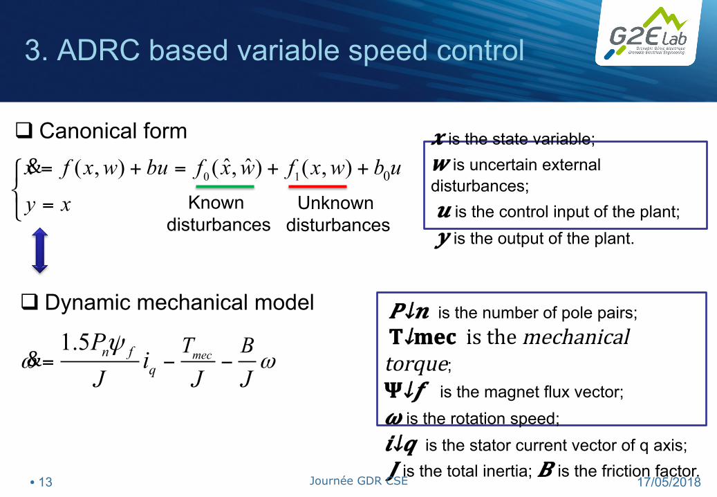
0 1 0ˆ ˆ( , ) ( , ) ( , )x f x w bu f x w f x w b u
y x
= + = + +
=
⎧⎨⎩
&
1.5mecn f
qT BP
iJ J J
ω ωψ
= − −&
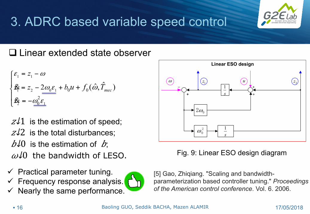
q Canonical form
q Dynamic mechanical model
𝒙 is the state variable; 𝒘 is uncertain external disturbances; 𝒖 is the control input of the plant; 𝒚 is the output of the plant.
Known disturbances
Unknown disturbances
𝑷↓𝒏 is the number of pole pairs; 𝐓↓𝐦𝐞𝐜 is the mechanical torque; 𝚿↓𝒇 is the magnet flux vector; 𝝎 is the rotation speed; 𝒊↓𝒒 is the stator current vector of q axis; 𝑱 is the total inertia; 𝑩 is the friction factor.
3. ADRC based variable speed control
• 13 17/05/2018 Journée GDR CSE
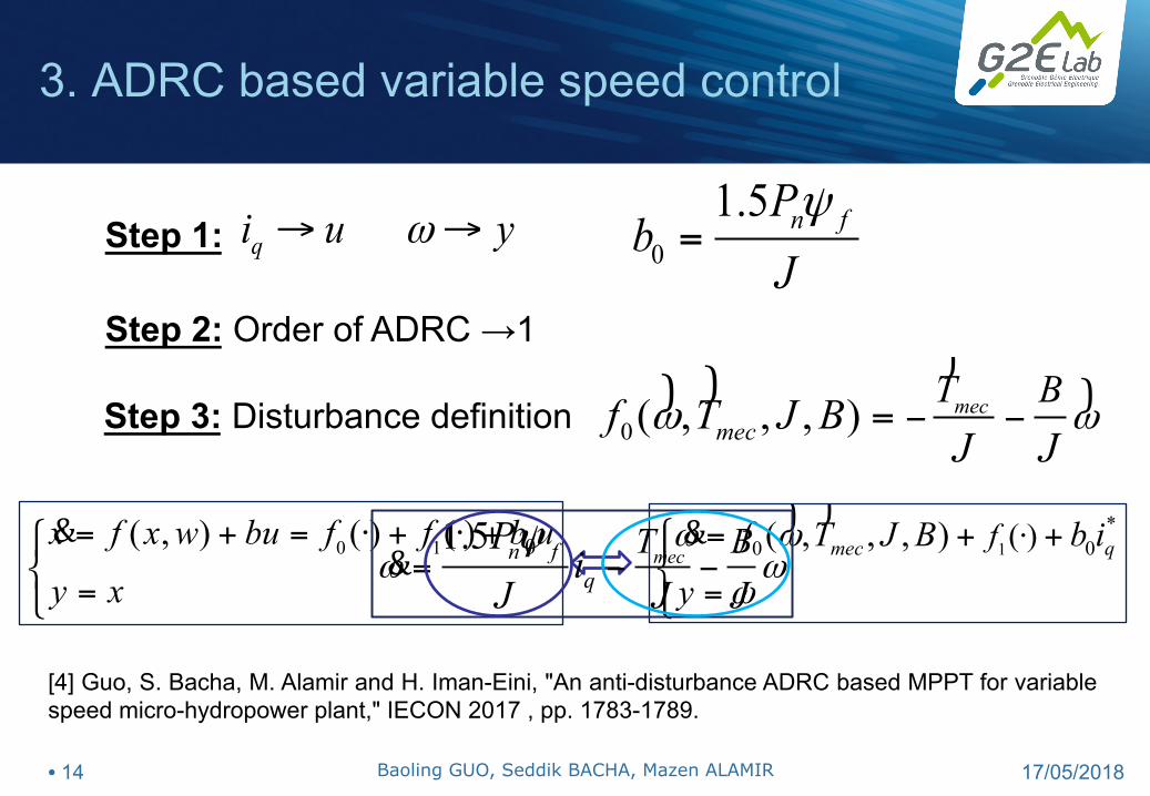
Step 3: Disturbance definition
0
1.5 n fPb
Jψ
=
0( , , , ) mecmec
T Bf T J BJ J
ωω − −=)
)))
qi u yω→ →Step 1:
Step 2: Order of ADRC →1
1*
0 0( )( , , , )mec qff T J B b iyω ω
ω
⋅⎧ = + +⎪⎨
=⎪⎩
))&0 1 0( , ) ( ) ( )x f x w bu f f b u
y x
= + = ⋅ + ⋅ +
=
⎧⎨⎩
& 1.5mecn f
qT BP
iJ J J
ω ωψ
= − −&
3. ADRC based variable speed control
[4] Guo, S. Bacha, M. Alamir and H. Iman-Eini, "An anti-disturbance ADRC based MPPT for variable speed micro-hydropower plant," IECON 2017 , pp. 1783-1789.
[5] Gao, Zhiqiang. "Scaling and bandwidth-parameterization based controller tuning." Proceedings of the American control conference. Vol. 6. 2006.
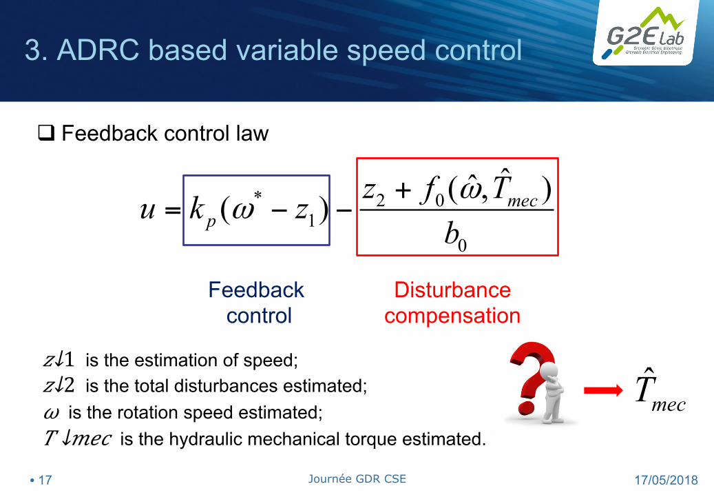
* 2 01
0
ˆˆ( , )( ) mecp
z f Tu k zbω
ω+
= − −
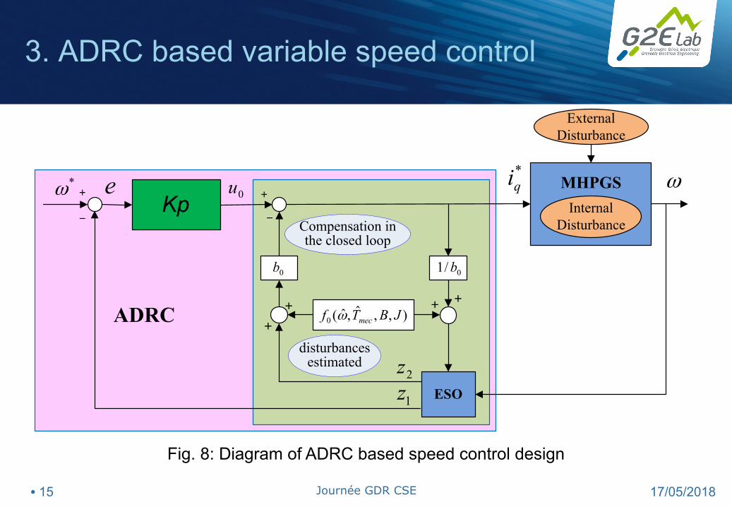
q Feedback control law
Feedback control
Disturbance compensation
𝑧↓1 is the estimation of speed; 𝑧↓2 is the total disturbances estimated; 𝜔 is the rotation speed estimated; 𝑇 ↓𝑚𝑒𝑐 is the hydraulic mechanical torque estimated.
[6] LIU, Z. G., & LI, S. H. (2008). Active disturbance rejection controller based on permanent magnetic synchronous motor model identification and compensation [J]. Proceedings of the CSEE, 24, 022.
Ø How to tune and apply the nonlinear ADRC more efficiently?
Ø ADRC based control applied to grid side control: DC bus
regulation and grid current control.
Ø How to estimate the high frequency disturbance?
Ø PI ↔ PR, ESO ↔ R-ESO?
• 30 17/05/2018 Journée GDR CSE
Thank you for your attention!
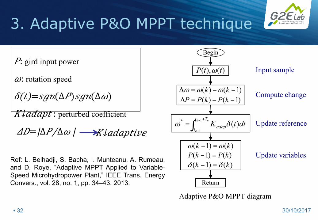
3. Adaptive P&O MPPT technique
Ref: L. Belhadji, S. Bacha, I. Munteanu, A. Rumeau, and D. Roye, “Adaptive MPPT Applied to Variable-Speed Microhydropower Plant,” IEEE Trans. Energy Convers., vol. 28, no. 1, pp. 34–43, 2013.
Begin
)(),( ttP ω
)1()( −−=Δ kk ωωω)1()( −−=Δ kPkPP
∫+−
−
=ek
k
Tt
t adap dttK1
1
)(* δω
)()1( kk ωω =−)()1( kPkP =−)()1( kk δδ =−
Return
Update variables
Input sample
Compute change
Update reference
Adaptive P&O MPPT diagram
𝑃: gird input power
𝜔: rotation speed
𝛿(𝑡)=𝑠𝑔𝑛(∆𝑃)𝑠𝑔𝑛(∆𝜔)
𝐾↓𝑎𝑑𝑎𝑝𝑡 : perturbed coefficient
𝛥𝐷=|∆𝑃⁄∆𝜔 | 𝐾↓𝑎𝑑𝑎𝑝𝑡𝑖𝑣𝑒
• 32 30/10/2017
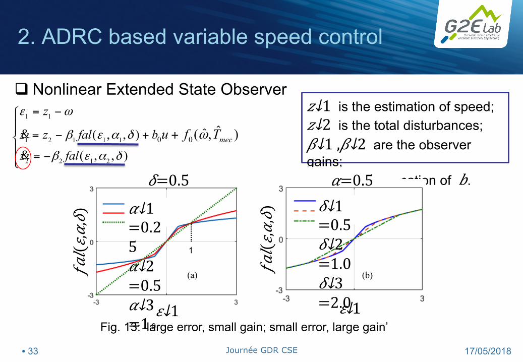
1 1
1 2 1 1 1
2 2 1 2
0 0( , , )
( , , )
ˆˆ( , )mec
z
z z fal b
z fal
u f T
ε ω
β ε α δ
β ε α δ
ω
= −
= − +
= −
⎧⎪
+⎨⎪⎩
&&
q Nonlinear Extended State Observer 𝑧↓1 is the estimation of speed; 𝑧↓2 is the total disturbances; 𝛽↓1 , 𝛽↓2 are the observer gains; 𝑏↓0 is the estimation of 𝑏.
Fig. 13: ‘large error, small gain; small error, large gain’
(a) (b)
𝜀↓1 𝜀↓1 0 0
𝛼↓1 =0.25
𝛼↓2 =0.5
𝛼↓3 =1.0
𝛿↓1 =0.5
𝛿↓2 =1.0 𝛿↓3 =2.0
𝛿=0.5 𝛼=0.5
2. ADRC based variable speed control
• 33 17/05/2018 Journée GDR CSE
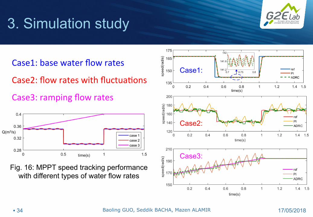
Q(m3/s)
Fig. 16: MPPT speed tracking performance with different types of water flow rates


![A Linear Active Disturbance Rejection Control applied for DFIG …ijcsi.org/papers/IJCSI-10-2-2-391-399.pdf · The active disturbance rejection control was proposed by Han [9][10][11][12].](https://static.documents.pub/doc/80x56/5f98d8fa7a6f683232427d6c/a-linear-active-disturbance-rejection-control-applied-for-dfig-ijcsiorgpapersijcsi-10-2-2-391-399pdf.jpg)


