Heckmann, A., Keck, A., Grether, G. : Active Guidance of a Railway Running Gear with Independently Rotating Wheels, 2020 IEEE Vehicle Power and Propulsion Conference, VPPC 2020 - Proceedings
Abstract—The development of railway running gears withindependently rotating wheels is a focus of research within theNext Generation Train project at DLR. The lateral guidanceof this type of running gears represents a challenging problemthat relies on active control. The paper introduces results onthis research regarding observer and control design that arefocused and demonstrated on a scaled experimental runninggear hardware that was specifically constructed for this purpose.Additionally, the development of the lateral guidance system issupported by simulation and optimization within a Modelicabased virtual simulation environment tailored for the modelingof railway vehicle dynamics in multi-domain engineering tasks.
Index Terms—railway running gear, observation and controlof independently rotating wheels, Modelica
I. INTRODUCTION
The label ”Next Generation Train” (NGT) entitles both,a long-term research project to which 11 DLR institutescontribute and a family of train concepts to consistentlydemonstrate the wide range of railway vehicle technologiesunder research at these institutes.
The major characteristics of the train design under in-vestigation are very high speed up to 400 km/h in dailyoperation, double deck configuration, light-weight design, im-proved passenger comfort, reduced life-cycle-costs and energyconsumption per passenger. As regards running gears, wheelpairs with independently rotating and driven wheels (IRW)were chosen because of their promising but so far unexploitedadvantages. This design offers the capability of almost perfectsteering along curves and facilitates continuous floors even on
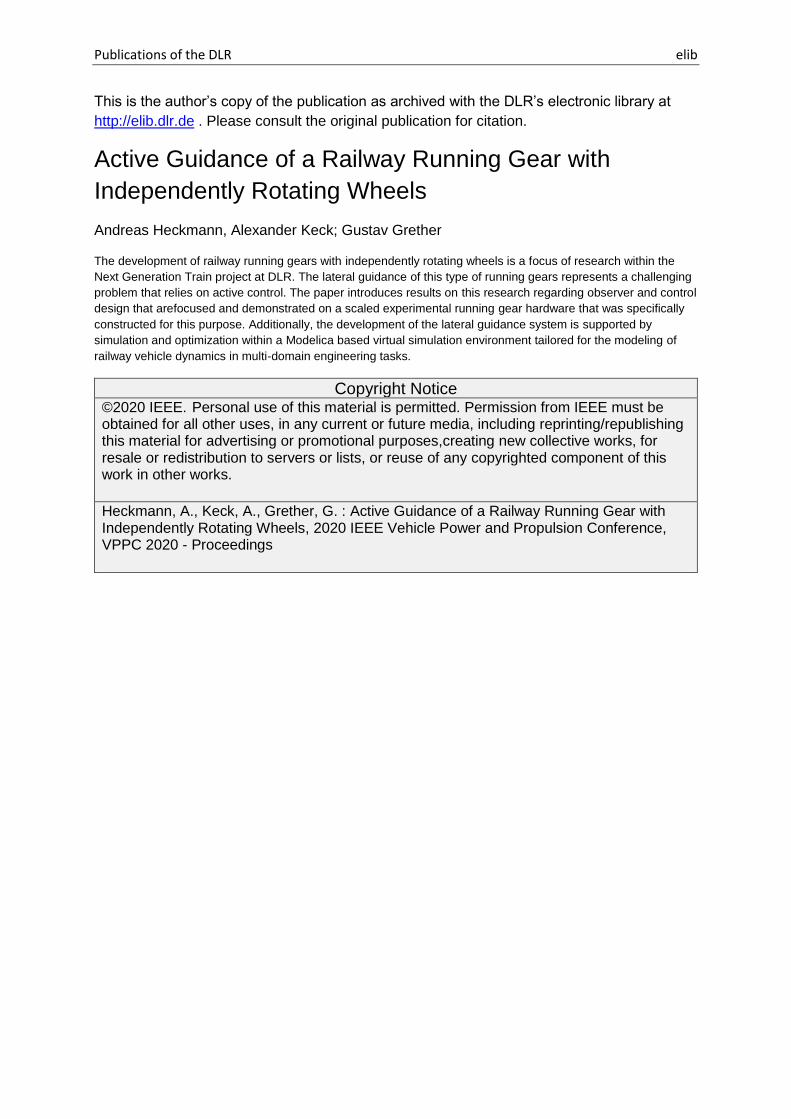
Fig. 1. Experimental IRW running gear on the 1:5 scale roller rig at DLR
the lower level of the double deck car body, which would haveto be stepped for a conventional wheel set axle. [1].
However, the task of guidance along the track or the lateraldynamics of the IRW, respectively, relies on active control inorder to minimize wear and noise. And furthermore, it dependson sufficiently precise information on the lateral position ofthe wheel pair relative to the track, which is difficult to directlymeasure in daily train operation. Against this background,this paper reports on the nonlinear control and observerdesign for the IRW that is theoretically investigated, virtuallysimulated and experimentally demonstrated using the exampleof a 1:5 scale experimental running gear that was specificallyconstructed for this purpose, see Fig. 1.
The paper is organized as follows: Sec. II introduces thedesign of the scaled experimental running gear hardware,Sec. III is dedicated to the simulation environment, Sec. IVpresents the observer design while Sec. V reports on thecontrol synthesis. The final Sec. VI concludes the paper, refersto accompanying work on true scale simulation models andgives an outlook.
II. EXPERIMENTAL RUNNING GEAR HARDWARE
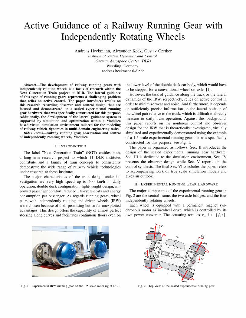
The major components of the experimental running gear inFig. 2 are the central frame, the two axle bridges, and the fourindependently rotating wheels.
Each wheel is equipped with a permanent magnet syn-chronous motor as in-wheel drive, which is controlled by itsown power converter. The actuating torques τi, i ∈ {f, r},
𝜔𝑓𝑙
𝜓𝑓
𝑦𝑓
𝜔𝑟𝑙
𝜔𝑟𝑟
𝜔𝑓𝑟
𝑦𝑟
𝜓𝑟
track centerline
Fig. 2. Top view of the scaled experimental running gear
where f denotes front and r rear, are applied to the wheels ofeach axle configuration in a differential manner, i.e. τij = ±τi,j ∈ {r, l}, where r signifies right and l left.
The axle bridges are connected to the running gear frame viaa leaf spring guidance. The mounting and the vertical springrepresent the primary suspension of the running gear. Thisconfiguration enables a yaw motion of the axle bridges, thatis limited by bump stops. The central frame is attached to theroller rig with a lemniscate guidance that locks the longitudinalmotion.
Fig. 2 displays the degrees of freedom of the running gear.These are the four wheel rotations with speeds ωij , the yawangles of the axle-bridges ψi and the lateral displacementsof the axle bridge centers yi, i ∈ {f, r}, with respect to thetrack centerline. For detailed description see [2], where theequations of motion are given as well.
The sensor equipment of the experimental running gear isset-up to examine and compare different observer configura-tions. It includes four rotary encoders at each wheel in orderto monitor ωij . At each axle bridge, an angle sensor measuresthe yaw angle ψi and an inertial measurement unit (IMU)i.a. provides information on yi and ψi. The signals of fourforce-torque sensors at the attachment points of each wheeldrive to the axle bridges are evaluated in such a way that theresultant lateral force Fy,i, the resultant vertical force Fz,i andthe resultant torque Mx,i around the longitudinal axis for eachaxle bridge are available and signal drift is canceled out.
In order to provide reference signals, laser distance sensorsbetween roller rig base and central frame are mounted tomeasure yi in addition. Under real life conditions at railway
tracks, these lateral positions are difficult to measure in areliable and robust manner, which motivates the design ofappropriate observers.
The rapid control prototyping system of the roller rigfacilitates processing of all sensor and actuator signals withinobserver and control algorithms in real-time.
III. SIMULATION ENVIRONMENT
Modeling, simulation and optimization are important toolsbesides hardware testing that offer the opportunity to examineand evolve new technical concepts in early design phaseswithout implementation risks and at comparabely low costs.
An attractive approach in the context of control developmentand multidomain simulation is the object-oriented modellinglanguage Modelica that is an open standard developed bythe non-profit Modelica Association [3]. Compared to block-oriented general environments, Modelica models are built upon mathematical equations that are symbolically pre-processedand do not rely on an a priori known signal flow [4]. Sincethe symbolic pre-proccessing may also include the inversionof nonlinear plant models, Modelica is in particular helpfulto systematically design model-based controllers for nonlinearsystems [5].
Moreover, Modelica supports an all-in-one-tool-approach,i.e. it provides the capability to cover multi-domain engi-neering tasks in one consistent simulation environment andis in particular tailored to represent of the dynamic behaviorof heterogeneous physical systems including e.g. mechanical,pneumatic, electric or hydraulic components.
As regards railway vehicle systems, the DLR Railway Dy-namics Library [6] shown in Fig. 3 has recently been released
Fig. 3. Overview on major items of the Modelica Railway Dynamics Library.
Fig. 4. Visualization of the experimental running gear model
and extends the wide range of domain specific componentlibraries that are publicly available either on a open source ora commercial basis. It supports the consideration of vehicledynamics issues such as traction, comfort and safety in multi-domain engineering tasks. Vehicle, track, wheel-rail contactmodels and roller rig scenarios are prepared on differentlevels of detail and offer interfaces to subsystem models thatrepresent e.g. electric propulsion engines, pneumatic brakesor control algorithms. Fig. 4 presents the visualization of thesimulation model used to develop and optimize the observationand control algorithms for the experimental running gear atDLR.
IV. OBSERVER DESIGN
Consider the unknown real life system
xxx = fff(xxx, u, vR) +µµµ , yyy = ggg(xxx, u, vR) + ρρρ (1)
of a single axle configuration, on which the discussion isfocused from now on, since observation and control of eachaxle is treated independently. The states and the outputs of thesystem are represented by xxx and yyy, while u denotes the systeminput and vR the given longitudinal speed. The process andmeasurement noise contributions µµµ and ρρρ are presumed to beadditive and Gaussian with zero mean.
The equations of motion from [2] are reformulated andextended to specify observer equations of the following form:
˙xxx = fff(xxx, u, vR)+LLL(xxx, u, vR)(yyy−yyy), yyy = ggg(xxx, u, vR) . (2)
Here, xxx and yyy symbolize the estimates of the associatedquantities in (1), while LLL(xxx, u, v) denotes the so far unkownrule to feed back the output error constituted by comparisonof the observer outputs yyy and the measurements of the reallife system yyy.
Two options appear: The more elaborate initial systemassumes the state vector xxx6
xxx6 = [yi, yi, ψi, ψi, ωir, ωil]T , (3)
while the reduced state vector xxx5 could be defined neglectingthe lateral wheel slip [7]:
yi ∼ v ψi =⇒ xxx5 = [yi, ψi, ψi, ωir, ωil]T . (4)
TABLE IEXPECTED ERROR DUE TO ERROR PROPAGATION OF SENSOR ACCURACIES
It is an important objective of research to examine severalalternative sensor configurations and to tell their properties.That is why the following three sensor compositions are takenunder consideration:
ggg3 = [ψi, ωir, ωil]T, (5)
ggg5 =[ψi, ωir, ωil, yi, ψi
]T, (6)
ggg6 = [ψi, ωir, ωil, Fy,i, Fz,i,Mx,i]T. (7)
A rigorous nonlinear observability analysis proved that ob-servability is given for both, the reduced and the full systemfor all sensor configurations as long as vR 6= 0. However,the low level configuration ggg3 might not be precise enoughduring acceleration or deceleration processes with high slipconditions.
Eqs. (5) to (7) may be used to analyze the expectedestimation error ∆yi, which follows from the specified sensorerrors and their propagation through the measurement equa-tions. The results in Table I present the advantage of the highlevel configurations ggg5 and ggg6 with respect to the estimationaccuracy.
Following the idea of the Kalman Filter, µµµ and ρρρ from (1)or the associated covariance matrices QQQ and RRR, respectively,could be used to substantiate the rule LLL(xxx, u, vR) for (2). Fornonlinear systems, several algorithms such as the Extended(EKF) or the Unscented Kalman Filter (UKF) exist thatprovide estimates of the current state variables along with theiruncertainties, cf. [8].
With this background, the specific synthesis task consistsof the design of QQQ and RRR in such a way that the convergenceof the estimation error is ensured. Provided that real lifemeasurement data yyy are available, numerical optimization ofthe following problem with multiple cases Sk ∈ S is anappropriate tool to do so [9]:
minν
maxSk∈S
ok(ν), ν := ([diag(QQQ),diag(RRR)]),
ok :=1
tk
∫ tk
0
|yyy − yyy| dt .(8)
Hereby, the set S is supposed to cover all relevant applicationscenarios and to truely represent the circumstances in dailyoperations including e.g. disturbances, parameter variations,switching operations and so on. The specific formulation ofthe optimization as a minimization of the worst case in (8) aswell supports the aim to get robust observer parametrization.
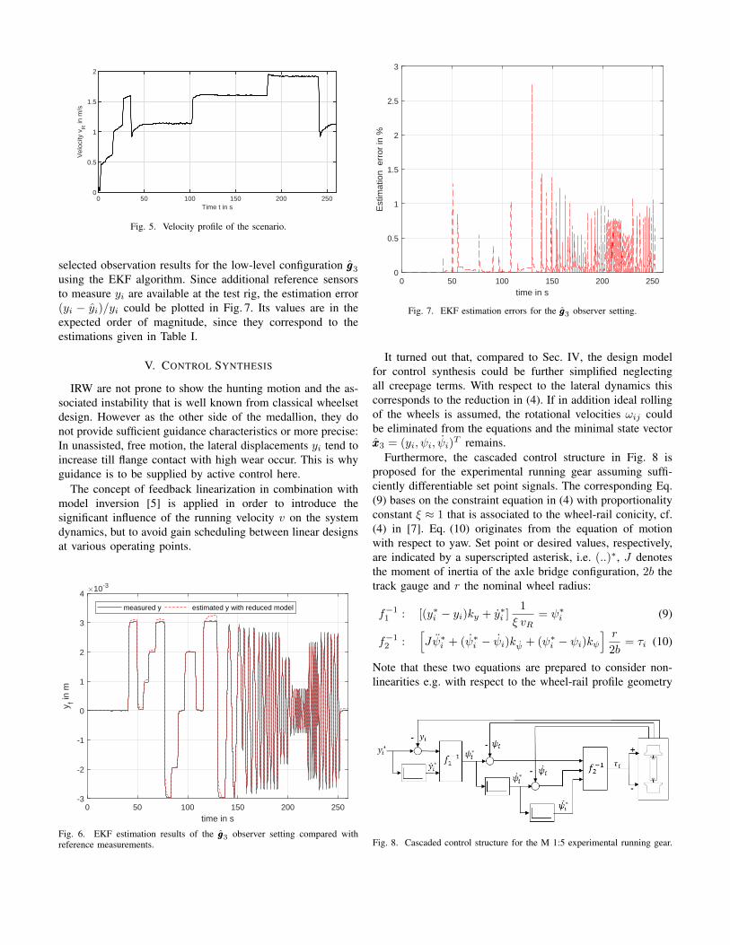
In order to define a demanding scenario and demonstratethe accuracy and robustness of the observer, fluctuating run-ning velocities according to Fig. 5 are specified. Fig. 6 shows
0 50 100 150 200 250Time t in s
0
0.5
1
1.5
2V
eloc
ity v
R in
m/s
Fig. 5. Velocity profile of the scenario.
selected observation results for the low-level configuration ggg3using the EKF algorithm. Since additional reference sensorsto measure yi are available at the test rig, the estimation error(yi − yi)/yi could be plotted in Fig. 7. Its values are in theexpected order of magnitude, since they correspond to theestimations given in Table I.
V. CONTROL SYNTHESIS
IRW are not prone to show the hunting motion and the as-sociated instability that is well known from classical wheelsetdesign. However as the other side of the medallion, they donot provide sufficient guidance characteristics or more precise:In unassisted, free motion, the lateral displacements yi tend toincrease till flange contact with high wear occur. This is whyguidance is to be supplied by active control here.
The concept of feedback linearization in combination withmodel inversion [5] is applied in order to introduce thesignificant influence of the running velocity v on the systemdynamics, but to avoid gain scheduling between linear designsat various operating points.
0 50 100 150 200 250
time in s
-3
-2
-1
0
1
2
3
4
y f in m
10-3
measured y estimated y with reduced model
Fig. 6. EKF estimation results of the ggg3 observer setting compared withreference measurements.
0 50 100 150 200 250
time in s
0
0.5
1
1.5
2
2.5
3
Est
imat
ion
err
or in
%
Fig. 7. EKF estimation errors for the ggg3 observer setting.
It turned out that, compared to Sec. IV, the design modelfor control synthesis could be further simplified neglectingall creepage terms. With respect to the lateral dynamics thiscorresponds to the reduction in (4). If in addition ideal rollingof the wheels is assumed, the rotational velocities ωij couldbe eliminated from the equations and the minimal state vectorxxx3 = (yi, ψi, ψi)
T remains.Furthermore, the cascaded control structure in Fig. 8 is
proposed for the experimental running gear assuming suffi-ciently differentiable set point signals. The corresponding Eq.(9) bases on the constraint equation in (4) with proportionalityconstant ξ ≈ 1 that is associated to the wheel-rail conicity, cf.(4) in [7]. Eq. (10) originates from the equation of motionwith respect to yaw. Set point or desired values, respectively,are indicated by a superscripted asterisk, i.e. (..)∗, J denotesthe moment of inertia of the axle bridge configuration, 2b thetrack gauge and r the nominal wheel radius:
f−11 : [(y∗i − yi)ky + y∗i ]1
ξ vR= ψ∗i (9)
f−12 :[Jψ∗i + (ψ∗i − ψi)kψ + (ψ∗i − ψi)kψ
] r
2b= τi (10)
Note that these two equations are prepared to consider non-linearities e.g. with respect to the wheel-rail profile geometry
Fig. 8. Cascaded control structure for the M 1:5 experimental running gear.
14 14.5 15 15.5 16 16.5 17 17.5 18
time in s
-0.5
0
0.5
1
1.5
2
2.5
3
3.5y f in
m10-3
-4
-2
0
2
4
6
8
10
12
14
psi i
n ra
d
10-3
measured y set point ymeasured psi* set point psi*
Fig. 9. Control optimization scenario
by specifying ξ = ξ(y, ψ) and r = r(y, ψ). Related benefitsand robustness issues are subjects of current research.
The three feedback gains µ := (ky, kψ, kψ) in (9) and (10)were specified by optimization. To this end, we define the setpoint trajectory in Fig. 9, which is a lateral displacement of3 mm within 2.5 s, but low-pass filtered with cut-off frequencyof 3 Hz. A constant speed v = 1 m/s is assumed.
The velocity profile in Fig. 5 was applied to demonstratethe implementation of the control at the experimental runninggear hardware in Fig. 10.
It is obvious that the IRW running gear is capable offollowing an almost arbitrary trajectory mainly limited bythe given track clearance and the available actuation power.The general objective of IRW control is to limit yi within aspecific range, where no flange contacts occur, so that wear andnoise emmissions are reduced. Active steering into curves withtransitions and not only reducing but evenly distributing wearby defining appropriate trajectories y∗i are further objectives.
However, real railway tracks are technical systems, whererail irregularities permanently excite the lateral motion of therunning gears. So the roller rig scenario here is an idealizedone and steady state accuracy is actually not a control designgoal in practise.
VI. CONCLUSIONS AND OUTLOOK
The paper presents the development of an observer andcontrol design for railway running gears with independentlyrotating wheels. Hereby, the presentation is focused on theM1:5 hardware constructed at DLR in order to provide an ex-perimental environment. The research is additionally supportedby virtual simulations and optimization within the Modelicabased Railway Dynamics Library. The transfer of the resultsto true scale systems is ongoing work and already preparedin M1:1 multibody simulations [10]. To go one step further,an experimental running gear in true scale is currently beeing
0 50 100 150 200 250
time in s
-3
-2
-1
0
1
2
3
4
y f in m
10-3
measured y set point y
Fig. 10. Comparison of the set point and the measured trajectory
constructed at DLR. It is expected to be available for firstexperiments in the course of the year 2021.
REFERENCES
[1] J. Winter, E. Mittelbach, and J. Schykowski, Eds., RTR Special - NextGeneration Train. Eurailpress, DVV Media Group, 2011.
[2] C. Schwarz, A. Heckmann, and A. Keck, “Different models of a scaledexperimental running gear for the DLR RailwayDynamics Library,” in11th International Modelica Conference, 21.-23. Sep. 2015, 2015.
[3] Modelica, “Modelica® - a unified object-oriented language forphysical systems modeling - language specification 3.4,” 2017,https://www.modelica.org/documents/ModelicaSpec34.pdf.
[4] M. Otter, H. Elmqvist, and S. Mattsson, “Multi-domain Modeling withModelica,” in CRC Handbook of Dynamic System Modeling, P. Fish-wick, Ed. Chapman & Hall, 2007, pp. 36.1 – 36.27.
[5] M. Thummel, G. Looye, M. Kurze, M. Otter, and J. Bals, “Nonlinearinverse models for control,” in Proceedings of the 4th InternationalModelica Conference, 2005, pp. 267–279.
[6] A. Heckmann, M. Ehret, G. Grether, A. Keck, D. Ludicke, andC. Schwarz, “Overview of the DLR RailwayDynamics Library,” in 13thInternational Modelica Conference, 2019.
[7] A. Keck, C. Schwarz, and T. Meurer, “Observer design for arailway running gear with independently rotating wheels,” in Joint8th IFAC Symposium on Mechatronic Systems and 11th IFACSymposium on Nonlinear Control Systems, 2019. [Online]. Available:https://elib.dlr.de/127878/
[8] J. Brembeck, “Nonlinear constrained moving horizon estimation appliedto vehicle position estimation,” Sensors, vol. 19, no. 10, p. 2276, 2019.[Online]. Available: https://elib.dlr.de/127735/
[9] A. Pfeiffer, “Optimization library for interactive multi-criteria optimiza-tion tasks,” in 9th International Modelica Conference, 2012.
[10] G. Grether, A. Heckmann, and G. Looye, “Lateral guidance controlusing information of preceding wheel pairs,” in Advances in Dynamics ofVehicles on Roads and Tracks, IAVSD2019. Lecture Notes in MechanicalEngineering, M. Klomp, F. Bruzelius, J. Nielsen, and A. Hillemyr, Eds.Springer, 2020, pp. 863–871.