Chapter 1 An overview of ASVC: from # laboratory curiosity to commercial products D. Guicking Drittes Physikalisches Institut, University of Gottingen, Gottingen, Germany, Email: guicking@physik3. gwdg. de A short historical review of active noise control is followed by brief discussions of the physical principles and basis concepts of technical realisations, grouped by the geometrical system topology (one-dimensional, local and three-dimensional control). The Section on active vibration control starts, again, with histori- cal remarks, followed by examples of technical applications to active mounts, buildings, active and adaptive optics and sound radiation control by structural inputs. The Chapter ends with a discussion of active flow control and some statistical data on publications in the field of active controls. 1.1 Introduction The concept of cancelling unwanted sound or vibrations by superimposing a compensation signal exactly in antiphase is not new. In acoustics, most of the early publications in this field are patent applications, showing that technical applications must have been intended. However, for a long time experiments were nothing more than laboratory demonstrations which were smiled at as cu- riosities, far from reality. Only modern electronics made technical applications feasible. The situation was different with the compensation of low-frequency mechanical vibrations; these techniques were used in practice at a very early Downloaded 23 Aug 2012 to 128.59.62.83. Term of Use: http://digital-library.theiet.org/journals/doc/IEEDRL-home/info/subscriptions/terms.jsp
Transcript
Chapter 1
An overview of ASVC: from #laboratory curiosity to commercialproducts
D. GuickingDrittes Physikalisches Institut, University of Gottingen, Gottingen, Germany,Email: guicking@physik3. gwdg. de
A short historical review of active noise control is followed by brief discussionsof the physical principles and basis concepts of technical realisations, grouped bythe geometrical system topology (one-dimensional, local and three-dimensionalcontrol). The Section on active vibration control starts, again, with histori-cal remarks, followed by examples of technical applications to active mounts,buildings, active and adaptive optics and sound radiation control by structuralinputs. The Chapter ends with a discussion of active flow control and somestatistical data on publications in the field of active controls.
1.1 Introduction
The concept of cancelling unwanted sound or vibrations by superimposing acompensation signal exactly in antiphase is not new. In acoustics, most of theearly publications in this field are patent applications, showing that technicalapplications must have been intended. However, for a long time experimentswere nothing more than laboratory demonstrations which were smiled at as cu-riosities, far from reality. Only modern electronics made technical applicationsfeasible. The situation was different with the compensation of low-frequencymechanical vibrations; these techniques were used in practice at a very early
Downloaded 23 Aug 2012 to 128.59.62.83. Term of Use: http://digital-library.theiet.org/journals/doc/IEEDRL-home/info/subscriptions/terms.jsp
4 Active Sound and Vibration Control
stage. In the following, an overview is given of the historical development,technical realisations and present research activities.
1.2 Active Noise Control
1.2.1 Early investigations
The first experiments on the superposition of sound fields were presumablymade in 1878 by Lord Rayleigh [246]. He describes under the heading 'Pointsof Silence' how he scanned, with his ear, the interference field produced by twoelectromagnetically synchronised tuning forks, and that he found maxima andminima of loudness. Although it can be assumed that these experiments shouldonly prove that coherent sound fields can interfere in the same way as do opticalfields (which was known since the days of Thomas Young), patent applicationsby Coanda [55, 56] and Lueg [181] aimed at possible noise reduction, howeveronly in Lueg's proposal in a physically realistic way. Lueg's German andespecially the related US application [179] with an additional sheet of drawingsare therefore considered rightly as the first written documents on active controlof sound.
Lueg had already proposed the usage of electroacoustic components, butthe first laboratory experiments were documented by Olson [227, 228] whoalso listed far-sighted prospective applications. Technical applications werenot possible at that time because of the clumsy electronic vacuum tube equip-ment, lacking sufficient versatility. Also, our ears present a problem, namelythe nearly logarithmic dependence of the perceived loudness on the sound pres-sure. For example, a sound level reduction by 20 dB requires an amplitudeprecision of the compensation signal within 1 dB and a phase precision withinsix degrees of the nominal values - for all frequency components of the noisesignal. These demands, together with the requirement of temporal stability,have impeded for a long time the technical use of coherent active compensa-tion of acoustical noise, also termed anti-sound, until in recent years digitaladaptive filters proved to be the appropriate tool.
1.2.2 The energy objection
In the context of the active cancellation of sound fields a question often posedis 'Where does the energy go?'. With the seemingly convincing argument thatthe primary field energy can only be enhanced by adding secondary soundsources, the concept of active noise control (ANC) is principally questionable.The objection is correct if the cancellation is achieved by interference only;a local cancellation leads to doubling of the sound pressure elsewhere. But a
Downloaded 23 Aug 2012 to 128.59.62.83. Term of Use: http://digital-library.theiet.org/journals/doc/IEEDRL-home/info/subscriptions/terms.jsp
An overview of ASVC: from laboratory curiosity to commercial products 5
more detailed consideration reveals that the secondary sources can, properlyplaced and driven, absorb the primary energy. In other situations, the sourcesinteract such that the radiation impedance is influenced and thereby the soundproduction reduced. This will be elucidated in the following sections.
1.2.3 The JMC theory
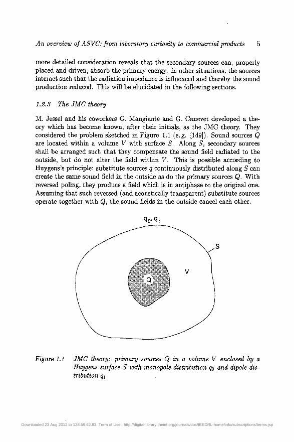
M. Jessel and his coworkers G. Mangiante and G. Canevet developed a the-ory which has become known, after their initials, as the JMC theory. Theyconsidered the problem sketched in Figure 1.1 (e.g. [149]). Sound sources Qare located within a volume V with surface S. Along 5, secondary sourcesshall be arranged such that they compensate the sound field radiated to theoutside, but do not alter the field within V. This is possible according toHuygens's principle: substitute sources q continuously distributed along 5 cancreate the same sound field in the outside as do the primary sources Q. Withreversed poling, they produce a field which is in antiphase to the original one.Assuming that such reversed (and acoustically transparent) substitute sourcesoperate together with Q, the sound fields in the outside cancel each other.
Figure 1.1 JMC theory: primary sources Q in a volume V enclosed by aHuygens surface S with monopole distribution qo and dipole dis-tribution qi
Downloaded 23 Aug 2012 to 128.59.62.83. Term of Use: http://digital-library.theiet.org/journals/doc/IEEDRL-home/info/subscriptions/terms.jsp
6 Active Sound and Vibration Control
If the cancellation sources are acoustic monopoles they radiate not only intothe outside but also into V", creating standing waves and enhancing the soundenergy in V. The inward radiation can be prevented by combining monopolesg0 along S with dipoles q\ so that the primary field in V is not altered. Asto the energy, the tripoles formed by the qo and qi (directional radiators withcardioid characteristic) absorb, along 5, the sound coming from Q. They serveas perfectly matched absorbers with an acoustic input impedance equal to thecharacteristic impedance of the medium.
With the same argument it follows that a source-free region V can activelybe shielded against sound influx from outside by arranging appropriate com-pensation sources along the surface S of V. Monopole distributions along Sreflect, tripoles absorb the incident sound.
For a given surface 5 and primary source distribution Q(r), where r isthe position vector, the substitution sources <fo(r) and qi(r) can be calculatedfrom the Helmholtz-Huygens integral equation which links the sound field ina region to the sound pressure and its gradient along the surface [185].
For practical applications, the theoretically required continuous source dis-tribution has to be replaced by discrete sources. Their minimal surface densityfollows from their absorption crosssection A = A2/4TT [235] and the smallestsound wavelength A for which the system shall be effective. This concepthas been verified in computer simulations [186] and experimentally in an ane-choic room [237]. A practical application is noise shielding of large open-airpower transformers by an array of loudspeakers to save the people living inthe surroundings from the annoying hum [168].
Primary and cancellation sound must have the same direction of propagation.It is therefore easier to cancel plane, guided waves in ducts (below the onsetfrequency of the first lateral mode) than, for example, three-dimensional soundfields in rooms with omnidirectional propagation. In a setup as sketched inFigure 1.2 (which has in principle already been proposed by Lueg in 1934) thesound incident from the left is received by the microphone and, after somesignal processing, fed to the loudspeaker such that to the right-hand side theprimary (solid wavy line) and the additional signal (dashed) cancel each other.
After Lueg's idea, the signal processing should comprise amplitude adjust-ment, sign reversal and time delay in accordance with to the acoustic pathlength. However, an Active Noise Control (ANC) system is not practically ap-plicable in this simple form. First, the acoustic feedback from the loudspeakerto the microphone has to be avoided and, second, in most cases it is necessary
Downloaded 23 Aug 2012 to 128.59.62.83. Term of Use: http://digital-library.theiet.org/journals/doc/IEEDRL-home/info/subscriptions/terms.jsp
An overview of ASVC: from laboratory curiosity to commercial products 7
microphone
primary noise ^^\^~*- Q ,**" ~ X X X > cancellation
signalprocessing
L J loudspeaker
Figure 1.2 Principle of active feedforward cancellation of sound in a duct
to follow up the transfer function adaptively since the time delay and spectraldecomposition can change as a result of temperature drift, superimposed flowand other environmental conditions. It is therefore common practice today toapply adaptive digital filters which are implemented on fast signal processorsto enable online updating. Figure 1.3 shows a typical block diagram (ampli-fiers, A/D and D/A converters, as well as antialiasing lowpass filters beingomitted).
The transfer function of the acoustic feedback path from the loudspeakerL to the reference microphone R is modelled by the feedback compensationfilter FCF so that the input signal x(t) of the main filter does not containcontributions from L. The error microphone E receives, in the case of incom-plete cancellation, an error signal e(t) which serves for the adaptation of themain filter A. The filter A adapts such that it models the acoustic transferfunction from R to L, including the (complex) frequency responses of R andL. The filters A and FCF are often realised as transversal filters (finite impulseresponse or FIR filters), and the most common adaptation algorithm is thefiltered-x LMS algorithm after Widrow and Hoff [337] where LMS stands forleast mean squares. The algorithm is controlled by the product e(t)x(t) andadjusts the filter coefficients by a stochastic gradient method so that x(t) ande(t) are decorrelated as far as possible. If the primary sound is broadband, thepropagation delay from L to E decorrelates x(t) and e(t) to a certain degreewhich impairs the performance of the ANC system. In order to compensatefor this effect, x(t) is prefiltered in the update path (lower left) with a modelHLE of the error path HLE. The necessary error path identification is per-formed with an auxiliary broadband signal of the noise generator NG in theadaptation unit shown at the lower right of Figure 1.3. The coefficients ofHLE (and also of FCF) are either determined once at startup and then keptconstant or, if the transfer functions vary too much with time, permanently;
Downloaded 23 Aug 2012 to 128.59.62.83. Term of Use: http://digital-library.theiet.org/journals/doc/IEEDRL-home/info/subscriptions/terms.jsp
8 Active Sound and Vibration Control
referencemicrophone
compensationloudspeaker
errormicrophone
primary sound
error signal
prefiiter
Figure 1.3 ANC in a duct by adaptive feedforward control with feedback can-cellation and error path identification for the filtered-x LMS al-gorithm
in the latter case, however, the (weak) auxiliary signal remains audible at theduct end since it is not compensated for by the loudspeaker signal y(t).
After adaptation the loudspeaker acts as a sound-soft reflector for the waveincident from the left which is, hence, not absorbed but reflected to the left.With a different control strategy the loudspeaker could be operated as an activeabsorber, but the maximum possible absorption is half of the incident soundpower; either one quarter are reflected and transmitted. The reason is that it isnot possible to achieve perfect impedance matching with a single loudspeakermounted at the duct wall. The incident wave 'sees' the parallel connectionof the loudspeaker input impedance and the characteristic impedance of theongoing part of the duct. (But a loudspeaker at the end of a duct can bedriven to perfectly absorb the incident sound [119].)
If the standing waves or the stronger sound propagation to the left inarrangements such as those in Figures 1.2 and 1.3 cannot be tolerated, a trueactive absorber can be realised with loudspeaker pairs or linear arrays [118,285, 339].
A series of commercial ANC systems working on the principle of sound-soft
Downloaded 23 Aug 2012 to 128.59.62.83. Term of Use: http://digital-library.theiet.org/journals/doc/IEEDRL-home/info/subscriptions/terms.jsp
An overview of ASVC: from laboratory curiosity to commercial products 9
reflection have been developed by the US company Digisonix and successfullyinstalled mainly in industrial exhaust stacks since 1987 [84]. The filters Aand FCF are combined to one recursive, infinite-impulse response (IIR) filter,often employing the Feintuch algorithm [91]. The signal processors allow on-line operation at least up to 500 Hz, suppress tonal noise by up to 40 dB andbroadband noise typically by 15 dB. Similar systems have also been installedin Germany [66, 123, 129] and elsewhere. The lower frequency limit is givenby pressure fluctuations of the turbulent flow, the upper limit by the compu-tational speed of the signal processor and the lateral dimensions of the duct.The higher modes occurring at higher frequencies can only be cancelled byusing a greater amount of hardware [88]; few such systems have therefore beeninstalled so far.
The filtered-x LMS algorithm is very popular because of its moderate sig-nal processing power requirement (the numerical complexity is O(2N) if Nis the filter length), but its convergence is very slow for spectrally colouredrandom noise. Fan noise spectra have typically a steep roll-off with increasingfrequency so that the convergence behaviour of the algorithm is often insuf-ficient. Efforts have therefore been made in recent years to develop fasteralgorithms which are still capable of being updated in real time. One exampleis the SFAEST algorithm [214] which is independent of the signal statisticsand has a complexity of O(8N). Since it further calculates the optimal filtercoefficients in one single cycle, it is particularly useful for nonstationary signalsand nonstationary transfer functions. Stability problems in the initialisationperiod could be solved by the FASPIS configuration [240, 256, 257]. More onalgorithms can be found in References [162, 304].
An important concept in many fields of ANC is adaptive noise cancellingwhich has become widely known since B. Widrow et aVs 1975 seminal paper[338] (see Figure 1.4). A primary sensor picks up a desired signal which iscorrupted by additive noise, its output being sp. One or more reference sensorsare placed such that their output sr is correlated (in some unknown way) withthe primary noise, but does not essentially contain the desired signal. Then, sr
is adaptively filtered and subtracted from sp to obtain a signal estimate withimproved signal-to-noise ratio (SNR) since the adaptive filter decorrelates theoutput and sr. This concept, realised by a linear predictive filter employingthe least mean squares (LMS) algorithm, has been patented by McCool etal. [194] and found wide applications especially in speech transmission from anoisy environment [264], but also in seismic exploration [336], medical ECGdiagnostics [335], a noise cancelling stethoscope [125] etc.
In adaptive feedforward control systems as shown in Figure 1.3 the soundpropagation path from microphone R to loudspeaker L must be long enough
Downloaded 23 Aug 2012 to 128.59.62.83. Term of Use: http://digital-library.theiet.org/journals/doc/IEEDRL-home/info/subscriptions/terms.jsp
10 Active Sound and Vibration Control
desired signalprimary sensor
output
noise
adaptive filter
D-reference sensor
y(t)
Figure 1.4 Adaptive noise cancelling
to provide the time required for calculating the signal to be fed to L (causalitycondition). The limiting factor is mostly not the computation time in thesignal processor but the group delay in the antialiasing lowpass filters whichare necessary in digital signal processing.
Problems in technical ANC applications are often posed by the loudspeak-ers. Very high low-frequency noise levels are typically encountered in exhauststacks or pipes, demanding high membrane excursions without nonlinear dis-tortion and, often, robustness against aggressive gases and high temperatures.On the other hand, a smooth frequency response function (as for hi-fi boxes)is not an issue because frequency irregularities can be compensated for by theadaptive filter. Special loudspeakers for ANC systems are being developed[44, 62, 72].
1.2.5 Interaction of primary and secondary sources
The ANC systems discussed in the preceding sections aimed at absorption orat least reflection of the primary sound power, tacitly assuming that primarypower radiation is not influenced by the cancellation sources. However, ifit is possible to reduce the primary sound production by the operation ofthe secondary sources, this will be a particularly effective method of noisereduction.
A monopole radiator of radius a with a surface particle velocity v producesa volume velocity go = 47ra2t;. The sound power radiated into a medium of
Downloaded 23 Aug 2012 to 128.59.62.83. Term of Use: http://digital-library.theiet.org/journals/doc/IEEDRL-home/info/subscriptions/terms.jsp
An overview of ASVC: from laboratory curiosity to commercial products 11
density p and sound velocity c at a frequency UJ (wavelength A, wave numberk = 2TT/A) is Po = P^2<ZO/(4TTC). Adding an equal but antiphase monopole ata distance d < A , produces a dipole which radiates the power Pi == P0(kd)2/S.Supplementing this dipole by another one to form a quadrupole, the radiatedpower is further reduced to P2 = Po(kd)4/l5, assuming kd <C 1 [211].
These conditions are correct if the volume velocity q is the same in allthree cases, but this is not necessarily so because ANC, by adding a compen-sation source in close proximity, does not only raise the multipole order, butcan also alter the radiation impedance Zr = Rr + juMr. The surroundingmedium acts upon a monopole with the radiation resistance Rro = 4na2pcand the mass load MrQ = Anazp (three times the replaced fluid mass), upona dipole with Rri = Rr0 - (fca)2/6 and Mri = Mr0/6, and on a quadrupolewith Rr2 = RTQ> (ka)4/45 and Mr2 = Mr0/45 [211]. The mass load leads toa reactive power, an oscillation of kinetic energy between primary and sec-ondary source (acoustical short-circuit). The product v2Rs determines theradiated (active) power. The particle velocity v of the primary source dependson its source impedance and the radiation resistance. A low-impedance source(sound pressure nearly load independent) reacts on a reduced radiation resis-tance Rs with enhanced particle velocity v so that the reduction of radiatedpower by the higher multipole order is partially counteracted. But the soundradiation of impedance-matched and of high-impedance (velocity) sources isreduced in the expected way by an antiphase source in the nearfield.
These relationships can be utilised, e. g. for the active reduction of noisefrom exhaust pipes (ships, industrial plants, automobiles with internal com-bustion engines). A large demonstration project was implemented as early as1980: the low-frequency hum (20 to 50 Hz) from a gas turbine chimney stackhas been cancelled actively by a ring of antisound sources [287]. Each loud-speaker has been fed from one microphone pair through amplifiers with fixedgain and phase settings. Such a simple open-loop control system was sufficientin this case owing to the highly stationary noise and its narrow frequency band.
The pulsating gas flow emanating from a narrow exhaust pipe is a very ef-ficient high-impedance monopole sound radiator; an adjacent antiphase sourceturns it into a dipole or, in the case of a concentric annular gap around theexhaust mouth, into a rotationally symmetric quadrupole. Active mufflers forcars using the principle of source interaction have often been proposed (e. g.Reference [47]), but practical installations are still lacking, for technical andeconomical reasons: the strong vibrational input beneath the car body, splashwater, thrown-up gravel and the hot, aggressive exhaust gas form a hostileenvironment for loudspeakers and microphones; furthermore, active systemshave to compete with the highly efficient and comparatively cheap conven-
Downloaded 23 Aug 2012 to 128.59.62.83. Term of Use: http://digital-library.theiet.org/journals/doc/IEEDRL-home/info/subscriptions/terms.jsp
12 Active Sound and Vibration Control
tional mufflers of sheet metal.
1.2.6 Waveform synthesis for (quasi)periodic noise
A conceptually simple adaptive algorithm has been developed by a Britishresearch team [47]. It assumes (quasi)periodic noise, the source of which isaccessible for obtaining synchronisation pulses (e.g. vehicle engine noise).The principle is explained in Figure 1.5. A loudspeaker is mounted next to theexhaust pipe end, and is fed from a waveform synthesiser, realised with digitalelectronics. An error microphone is placed in the superposition zone and yieldsa control signal by which the loudspeaker output is optimised. The sync pulses(obtained, e. g., by a toothed wheel and an inductive probe) guarantee that thecompensation signal tracks changing engine rotation speed automatically. Thewaveform is adapted using a trial-and-error strategy either in the time domainor, more quickly, in the frequency domain. In the latter case, the amplitudesand phases of the (low-order) harmonics of the engine noise are adapted. Theprominent feature of this active system is that no microphone is required toreceive the primary noise because the signal processor performs the waveformsynthesis by itself. The loudspeaker must only provide the necessary acousticpower; resonances, nonlinearities and ageing are automatically compensatedfor. A disadvantage is the slower convergence as compared with true adaptivealgorithms.
An example for a technical application of ANC with waveform synthesisin medicine is a noise canceller for patients undergoing a magnetic resonanceimaging (MRI) inspection. The annoying impulsive noise is cancelled withthe help of a pneumatic headset, made entirely of plastic material since noferromagnetics and preferably no metal at all should be brought into the MRItube [76].
error microphone
O
synchronisation pulse
Figure 1.5 Active cancellation of (quasi)periodic noise by tracking controlwith sync input and waveform synthesis
Downloaded 23 Aug 2012 to 128.59.62.83. Term of Use: http://digital-library.theiet.org/journals/doc/IEEDRL-home/info/subscriptions/terms.jsp
An overview ofASVC: from laboratory curiosity to commercial products 13
1.2.7 Small volumes - personal noise protection
An acoustically simple ANC problem is presented by an enclosure the dimen-sions of which are small compared with the wavelength even at the highestfrequencies of interest. The sound pressure is then spatially almost constant,and the cancelling source can be placed anywhere in the enclosure. Correctlyfed, it acts as an active absorber.
One such small enclosure is the space between headphones and ear drum.The idea of personal noise protection by actively controlled headphones wasoriginally documented in a Russian patent application [41] in 1960, but reliablesignal processing was, in spite of intense research work in many countries,possible only very much later. Nearly simultaneously the US company Bose[196] and Sennheiser in Germany [320] presented active headsets for aircraftpilots; these have also been produced by other companies, as general purposehearing protectors for low-frequency noise.
1.2.8 Local cancellation
Placing an anti-source in the immediate near-field of a primary noise sourcegives a global effect, as explained in Section 1.2.5, but if the distance betweenthe two sources gets wider, then only local cancellation by interference remains[235]. Such systems did not, however, receive general attention because of theirvery limited spatial range of efficiency (in the order of A/10). Testers also dis-liked the strong sound level fluctuations which occurred when they movedtheir heads. But local cancellation can be very useful for acoustic laborataryexperiments, such as head-related stereophony when dummy head recordingsare reproduced by two loudspeakers [259]. As the sound radiated from the leftloudspeaker should be received by the left ear only, a compensation signal issuperimposed onto the right channel which cancels the sound coming from theleft loudspeaker to the right ear, and vice versa, see Figure 1.6. As comparedto the familiar source localisation between the loudspeakers of a conventionalstereo set, this procedure provides true three-dimensional sound field repro-duction with source localisation in any direction, including elevation, and alsogives a reliable distance impression.
Of great practical relevance is local active sound field cancellation for tele-conferencing and hands-free telephones (speakerphones) in order to compen-sate, at the microphone location, for acoustic room echoes which degrade thespeech quality and tend to cause howling by self-excitation (dereverberationof the room response) [124, 160].
A related older problem is the removal of electric line echoes in long-distance telephony with satellite communication links where the long trans-
Downloaded 23 Aug 2012 to 128.59.62.83. Term of Use: http://digital-library.theiet.org/journals/doc/IEEDRL-home/info/subscriptions/terms.jsp
14 Active Sound and Vibration Control
Figure 1.6 Crosstalk cancellation in stereophonic sound field reproductionwith loudspeakers by prefiltering. S = S(LO) and A = A(u)are nearside and farside transfer functions, respectively, betweenloudspeakers and eardrums; circles to the left from the loudspeak-ers indicate filters with inscribed transfer functions, C = C{u)) =
mission path also leads to speech degradation by audible echoes [274]. Thesignals are reflected from an impedance mismatch at the so-called hybrid wherethe two-wire line branches into the four-wire local subscriber cable. The geo-stationary satellites are positioned at 36000 km height so that the echo re-turn path (transmitter -> satellite -» receiver -* satellite -> transmitter) is4 x 36 000 km which yields an echo delay time of nearly 0.5 s.
Locally effective ANC systems with compact microphone/loudspeaker sys-tems in feedback configuration have been described by Olson as early as 1956[227]; they absorb low-frequency sound in a narrow space around the micro-phone and have been proposed for aircraft passengers and machine workers[71].
The application of acoustic echo cancellation has also been proposed forultrasonic testing where flaw echoes can be masked by strong surface echoes.It is possible to subtract the latter from the received signal and so improve thedetectability of flaws [110, 137]. Similarly, the ANC technique can be appliedto cancel the reflection of the ultrasonic echo from the receiver [127].
1.2.9 Three-dimensional sound fields in enclosures
The active cancellation of complex sound fields in large rooms, possibly withnonstationary sources and time-varying boundary conditions, is far beyond the
Downloaded 23 Aug 2012 to 128.59.62.83. Term of Use: http://digital-library.theiet.org/journals/doc/IEEDRL-home/info/subscriptions/terms.jsp
An overview of ASVC: from laboratory curiosity to commercial products 15
scope of present ANC technology. More realistic is the concept of reducingroom reverberation by placing active absorbers along the walls. The incidentsound is received by microphones which feed the loudspeakers so that theiracoustic input impedance is matched to the sound field. The situation is thesame as that in Figure 1.1 if the enclosure walls are considered as a Huygenssurface. The loudspeakers can also be driven so that their reflectivity takesarbitrary values in a wide range (experimentally, reflection coefficients between0.1 and 3 have been realised). This would facilitate the construction of a roomwith adjustable reverberation time [331], but at present still with a prohibitiveamount of hardware.
Intense research has been devoted to the active cancellation of sound insmall enclosures such as vehicle cabins. Four-stroke internal combustion en-gines have an inherent unbalance at twice the rotational speed (the secondengine order) which often coincides with the frequency of the fundamentalcabin resonance of cars, so exciting the highly annoying boom. Since thisnoise is strongly synchronised with the engine speed, its active cancellation ispossible with a relatively small amount of hardware and software [79]. It has,however, only been offered in a production car for some time by Nissan fortheir model Bluebird in Japan. Many other car manufacturers have developedtheir own systems, and some of them have successfully built prototypes, butall of them are hesitating for several reasons to install the ANC systems inseries production.
More involved is the cancellation of broadband rolling noise, both insideand outside the car. Laboratory experiments and driving tests have led topreliminary solutions; the nonstationarity of the noise input and of the acous-tic transfer functions demand fast adapting algorithms, also for error pathidentification [32, 37, 256, 257]. The noise and vibration problems are becom-ing more severe with the small low-consumption cars now under development;they will possibly be equipped with both ANC for the interior space and ac-tive vibration control (AVC) for the engine and wheel suspensions. For moreluxurious cars the trend in the automobile industry goes to combining ANCtechnology with "sound quality design" for the car interior so that the driverhas the choice, e.g. of a more silent car or a more sportive sound [97, 255].
Also, for economic reasons, the aircraft industry tends to replace, for shortand medium distances, jet engines by propeller (or turboprop) aircraft whichare, however, much louder in the cabin. Relatively little effort is necessary toemploy a technology known as synchrophasing. The eddy strings separatingfrom the propeller blade tips hit the fuselage and excite flexural vibrations ofthe hull which radiate sound into the cabin. If the right and left propellerare synchronised so that their "hits" meet the fuselage out of phase instead
Downloaded 23 Aug 2012 to 128.59.62.83. Term of Use: http://digital-library.theiet.org/journals/doc/IEEDRL-home/info/subscriptions/terms.jsp
16 Active Sound and Vibration Control
of simultaneously, then higher-order shell vibrations are excited which radiateless and so reduce the noise level inside [99]. Better results, however, withmore involved installations are obtained with multichannel adaptive systems.A European research project with the acronym ASANCA has resulted in atechnical application [152].
An important issue in ANC applications to three-dimensional sound fieldsis the placement of microphones and loudspeakers. Attention has to be paidnot only to causality, but also to observability and controllability, in particularin rooms with distinct resonances and standing waves (modal control). If, forsome frequency, the error microphone of an adaptive system is positioned in asound pressure node it does not receive the respective frequency component orroom mode so that no cancelling signal will be generated and no adaptationis possible. If the loudspeaker is placed in a node, then a compensation signalcalculated by the processor cannot effectively be radiated into the room, whichusually leads to higher and higher signal amplitudes and finally to an overloaderror of the digital electronics.
1.2.10 Free-field active noise control
Technical applications of ANC to three-dimensional exterior noise problemsare still quite rare, but many research projects have been reported and anumber of patents exist. The problems with active mufflers for cars withinternal combustion engines were discussed in Section 1.2.5. A technicallysimilar problem is the fly-over noise of propeller aircraft which mainly consistsof two components: the propeller blade tip vortex threads and the equallyimpulsive exhaust noise. If the exhaust tail pipe is shifted to a position nearto the propeller plane, and if the angular position of the propeller on its shaftis adjusted so that in a downward direction the pressure nodes of one sourcecoincide with the antinodes of the other one, then the destructive interferencereduces the fly-over noise by several dB [154].
A method for reducing traffic noise by cancelling the tyre vibrations of anautomobile is disclosed in Reference[321], proposing electromagnetic actuationof the steel reinforcement embedded into the tyres.
A frequently investigated problem is the cancellation of power transformernoise, either by loudspeakers arranged around the site [60], by force input tothe oil in which the transformer is immersed [49] or to the surrounding tankwalls [135], or by sound insulating active panels enclosing the transformer[113, 133]. Experimental results are discussed in Reference [13].
Downloaded 23 Aug 2012 to 128.59.62.83. Term of Use: http://digital-library.theiet.org/journals/doc/IEEDRL-home/info/subscriptions/terms.jsp
An overview ofASVC: from laboratory curiosity to commercial products 17
1.3 Active Control of Vibrations
1.3.1 Early applications
In contrast to ANC, AVC has long been applied, in particular to ships. Mallockreported in 1905 on vibration reduction on a steam ship by synchronisation ofthe two engines in opposite phase [184], Hort in 1934 on the reduction of rollmotion by an actively driven Prahm tank [136] (water is pumped between tankslocated on the two sides of the ship) and Allen in 1945 on roll stabilisation bybuoyancy control with activated fins, auxiliary rudders with variable angle ofattack protruding laterally from the ship hull into the water [9]. The lattertechnology is still practiced today.
Active damping of aircraft skin vibrations was proposed in 1942 [319],providing multichannel feedback control with displacement sensors and elec-tromagnetic actuators, mainly in order to prevent fatigue damage.
Early publications can also be found on the active control of vibrationsin beams, plates and composite structures. In mechanical wave filters wherea desired longitudinal wave mode in a bar is superimposed by an interferingdetrimental flexuraJ wave mode, the latter can be damped by pairs of piezoelec-tric patches on either side of the bar which are connected through an electricalresistor [192].
In special environments, e. g. ultrahigh vacuum, magnetic bearings withoutlubricants are preferred for rotating machinery, but their inherent instabilityrequires feedback control which equally reduces vibrations [14].
An early NASA patent [166] provides an active mass damper (see Section1.3.4) to cancel structural vibration.
In the 1980s, longitudinal vibrations of the ship superstructure caused bynonuniform propulsion have been compensated for with a type of dynamic ab-sorber, realised by a centrifugal pendulum. This is a pendulum swinging alongthe length of the ship and rotating about an axis pointing also in a lengthwisedirection. The swinging of the pendulum is synchronised to the ship's vibra-tion by controlling the rotational frequency, and hence the centrifugal force,which together with gravity determines its natural frequency [188].
1.3.2 AVC for beams, plates and structures
Air and spacecraft have had a great impact on investigations in active control ofstructural vibration. Other than the abovementioned whole-body vibrations ofships which are comparatively easy to control due to their very low frequencies,elastic structures, i. e. continuous media with an infinite number of degrees offreedom the control of which presents fundamentally different problems, must
Downloaded 23 Aug 2012 to 128.59.62.83. Term of Use: http://digital-library.theiet.org/journals/doc/IEEDRL-home/info/subscriptions/terms.jsp
18 Active Sound and Vibration Control
also be considered. First, there are the different wave types in solids (of whichlongitudinal, torsionaJ and transversal waves are the most important), andtheir control demands various types of actuator and sensor.
frequency
Figure 1.7 Spillover: attempting to control mode N at its resonance fre-quency /N also excites neighbouring modes N — 1 and N +1 withlower, but finite amplitudes
Furthermore, the propagation speed is generally higher in water than inair so that causality problems occur with broadband adaptive feedforwardcontrollers. As a consequence, many problems are treated with modal controlwhere, especially in the case of overlapping modes, the spillover problem hasto be considered: the unwanted excitation of additional modes the resonancecurves of which extend to the controlled frequency. In Figure 1.7 it is assumedthat the iVth mode resonant at frequency /# shall be controlled; the tails ofthe neighbouring resonance curves have nonnegligible amplitudes at /# (thedots on the dashed line) and are therefore also excited by the control signalat /iv, to some extent. Owing to the phase slope around a resonance, theneighbouring modes are usually enhanced rather than damped when the iVthmode is suppressed.
For satellites, the damping of modal vibrations is important after pointingposition manoeuvres etc. since they are built from low-loss materials and airfriction is not present in space. The optimisation of number and placementof sensors and actuators for the mostly applied adaptive feedback controllersrequires precise knowledge of the structural dynamics so that reliable modellingin state-space coordinates and a realistic estimation of discretisation errors arepossible. An introduction to this field is given by Meirovitch [203].
Sophisticated controllers have been designed to actively isolate satellite
Downloaded 23 Aug 2012 to 128.59.62.83. Term of Use: http://digital-library.theiet.org/journals/doc/IEEDRL-home/info/subscriptions/terms.jsp
An overview of ASVC: from laboratory curiosity to commercial products 19
antennas and installations for, e. g., microgravity experiments from structuralvibrations caused by the position controllers and other onboard machinery[73].
Damping and stiffness control in mechanical junctions can be achieved bydry friction control where the pressing force is controlled by a piezoelectric ac-tuator, in feedforward or feedback control, typically by a nonlinear algorithm,e.g. a neural network [107].
In aircraft technology, active controllers have been developed for manoeu-vre and gust load alleviation, as well as for wing flutter control [96], andfor noise and vibration reduction in helicopters [54, 130]. Currently, intenseresearch is devoted to the application of modern compound materials with em-bedded actuators and sensors (keywords are: bi-functional elements, adaptiveor smart structures, adaptronics [101, 204]) where technical problems are en-countered, among others, by the fact that sensor and actuator materials suchas piezoceramics, piezopolymers, electro and magnetostrictive materials, shapememory alloys, electro and magnetorheological fluids (smart materials) are notconstructional materials with a mechanical strength sufficient for load-bearingstructures. Much information on research in the field of smart materials andstructures is published in specialised journals such as Smart Structures andMaterials or Journal of Intelligent Material Systems and Structures.
1.3.3 Active mounts
Possibilities for active noise control in road vehicles were discussed in Sec-tion 1.2.9. The predominant sources of interior noise are engine and wheelvibrations which propagate as structure-borne sound through the car bodyand finally radiate as airborne sound into the cabin. It is therefore reasonableto develop active engine mounts and active shock absorbers which are stiffenough to carry the static load, but dynamically resilient so that vibrationsare not transmitted. Piezoceramic actuators are suited for excursions in thesubmillimetre range [73], for larger amplitudes and forces at frequencies of afew Hertz hydraulic and pneumatic actuators are available [278]. However,the commercial use of engine and wheel mounts has been impeded so far bytechnical problems. Compact and robust combinations of conventional rubbermounts with electrodynamicaJly driven hydraulics have been constructed asactive hydromounts for a wide frequency range [157, 330], but the stroke andpower required for cars at low frequencies cannot yet be fulfilled by activehydromounts of reasonable size [254].
Active control technology has been applied for improved vibration isolationof tables for optical experiments, scanning microscopes, vibration sensitive
Downloaded 23 Aug 2012 to 128.59.62.83. Term of Use: http://digital-library.theiet.org/journals/doc/IEEDRL-home/info/subscriptions/terms.jsp
20 Active Sound and Vibration Control
semiconductor manufacturing stages etc. Commercial products are offeredby companies such as Newport (USA), Halcyonics (Germany) and IntegratedDynamics Engineering (IDE, Germany), the latter company also offers activecompensation systems for electromagnetic strayfields which is important, e. g.,for high-resolution electron microscopes.
The performance of hydraulic shock absorbers can be improved by applyingelectrorheological fluids (ERF) [210]. ERF are fine suspensions of polarisablesmall dielectric particles in an unpolar basic fluid, e. g. polyurethane in low-viscosity silicone oil [15]. Their viscosity can be adjusted reversibly betweenwatery and pasty by applying electrical fields of several kV/mm.
Also suitable are magnetorheologicaJ fluids (MRF), suspensions of smallferromagnetic particles in a fluid, requiring a magnetic field for the viscosityto be changed. The field is usually applied by electromagnets which demandhigh electric current instead of high voltage [289].
1.3.4 Civil engineering structures
Wind-induced swaying of modern tall, high-rise buildings can amount to am-plitudes of several metres in the upper storeys. These can be damped bytuned mass dampers (TMD) acting as resonance absorbers: masses of about1 per cent of the total mass of the building are placed in the uppermost storeyand coupled to the building structure through springs and dampers. Theirperformance is raised by actively enhancing the relative motion. A promi-nent example where such an active TMD has been installed is the CitycorpCenter in New York [236]. Less additional mass is required for aerodynamicappendages, protruding flaps that can be swivelled and utilise wind forces likesails to exert cancelling forces on the building [46].
Many research activities in the USA, Canada and particularly Japan aim atthe development of active earthquake protection for buildings where, however,severe technical problems have still to be solved [146].
For slim structures such as antenna masts, bridges etc. tendon controlsystems have been constructed for the suppression of vibrations by controlledtensile forces acting in different diagonal directions [275].
1.3.5 Active and adaptive optics
The quality of pictures taken with optical or radio astronomical mirror tele-scopes depends essentially on the precision to which the optimal mirror shapeis maintained. Modern swivelling large telescopes suffer from deformation un-der their own weight which is compensated for more efficiently by active shapecontrol than by additional stiffeners which inevitably increase the mass of the
Downloaded 23 Aug 2012 to 128.59.62.83. Term of Use: http://digital-library.theiet.org/journals/doc/IEEDRL-home/info/subscriptions/terms.jsp
An overview of ASVC: from laboratory curiosity to commercial products 21
structure. This technology is called active optics [260].Although these motions are very slow (frequencies below 10 Hz) and there-
fore easy to control, adaptive optics have solved the more complicated problemof controlling picture blurring from atmospheric turbulence, the so-called see-ing which fluctuates at frequencies of about 1000 Hz. The mirror surface restson a matrix of piezoceramic actuators which are adjusted by an adaptive mul-tichannel controller so that a reference star is optimally focused. If no referencestar exists in the vicinity of the observed object an artificial guide star can becreated by resonance scattering of an intense laser beam from sodium atomsin about 100 km height [68, 98]. Adaptive optics have improved the opticalresolution of the best telescopes by a factor of 10 to 50. This technology,originally conceived in the 1950s, was developed in the USA during the 1970sfor the military SDI project and was not declassified before 1991 when civilresearch had reached almost the same state [57]. Meanwhile, adaptive opticalmirrors also find industrial applications such as laser cutting and welding [26].
1.3.6 Noise reduction by active structural control
Active control of structural vibrations and active control of sound fields havedeveloped almost independently, including differing adaptive control concepts(mostly feedforward in acoustics, mostly feedback in vibration). It has onlybeen in recent years that the two fields have become connected. Many noiseproblems result from radiation of structure-borne sound, e. g. in the interiorof cars and aircraft, on ships, by vibrating cladding panels of machines etc.Here comes into action a concept known under the acronym ASAC (ActiveStructural Acoustic Control) [102] where noise reduction is not attained bysuperimposing airborne sound onto the disturbing noise field but by controllingthe vibrating structure itself. This is possible by suitably placed and controlledactuators to suppress the structural vibration, although this is not necessarilythe optimal solution. Acoustically relevant are mainly plate bending waveswhich due to their frequency dispersion (cB oc <Ju) are nonradiating for UJ <ujg and radiating above the critical frequency ug at which the bending wavevelocity equals the sound velocity in the surrounding medium. When CB < CQthe acoustical short circuit between adjacent wave crests and troughs yields aweak sound radiation into the far field, but for CB > Co a very effective radiationresults. The proportionality factor in CB OC y/uj contains the flexural stiffnessso that its modification shifts the critical frequency and can turn radiatingmodes into nonradiating ones (modal restructuring). Much work has beendone to investigate how, e. g. by laminates from sheet metal and piezolayersas sensors and actuators, adaptive structures can be constructed which can
Downloaded 23 Aug 2012 to 128.59.62.83. Term of Use: http://digital-library.theiet.org/journals/doc/IEEDRL-home/info/subscriptions/terms.jsp
22 Active Sound and Vibration Control
suppress in propeller aircraft etc. the abovementioned fuselage excitation byeddy threads, so enabling a substitution or at least a supplement to the moreinvolved (and heavier) direct noise control by mirophone/loudspeaker systems[53, 101].
1.4 Active Flow Control
Coherent active control technology is also applied to fields other than soundand structural vibrations, among which the physics of fluid flow is gainingmore and more importance. One of the many interactions of sound and flow isthe transition from laminar flow of a slim gas flame into turbulence by insoni-fication. Conversely, the turbulence of a flame has been suppressed activelyby feedback control of a microphone/loudspeaker system [67].
Laboratory experiments have shown since about 1982 that the transitionfrom laminar to turbulent flow can be delayed by controlling the Tollmien-Schlichting waves in the boundary layer, thereby providing drag reductionwhich is of great technical relevance. This can be achieved with thermal inputs[176] and acoustical or vibrational excitation [74, 90, 187].
Also, the dangerous surge and stall in compressors, resulting from a com-pressor instability, can be suppressed acoustically [126].
It is also interesting that the active control of sound fields - which is gen-erally restricted to linear superposition - controls a highly nonlinear processin these applications [94].
An ionised gas stream in a combustion chamber (e. g. in a rocket) tendsto produce unstable resonance oscillations which can be suppressed by an ap-propriately controlled electric d.c. current through the ionised gas, employinga feedback controller with a photoelectric cell as oscillation sensor [20].
A microelectromechanical system (MEMS) to be mounted on fan bladesis presented in Reference [169], comprising a turbulence sensor, an integratedcircuit and an actuator by which turbulence noise can either be reduced, or- in the case of heat exchangers ~ amplified in order to improve heat trans-fer. Recent experiments on this interesting technique have been described inReference [134] where flight control of a delta wing aircraft is reported, and inReference [33] where the laminar/turbulent transition along a wing profile ina wind tunnel is influenced.
Blade-vortex interaction causing impulsive noise from helicopters can bereduced by controlling flaps at the trailing edges [50]. In a further develop-ment, tip vortices of helicopter blades, aircraft foils or marine propellers canbe reduced by fluid injection to the high-pressure side of the lifting body [221].
Downloaded 23 Aug 2012 to 128.59.62.83. Term of Use: http://digital-library.theiet.org/journals/doc/IEEDRL-home/info/subscriptions/terms.jsp
An overview of ASVC: from laboratory curiosity to commercial products 23
Dynamic stabilisation of jet-edge flow with various adaptive linear feedbackcontrol strategies has been experimentally verified [243].
Disturbing resonances in a large wind tunnel with free-jet test section (theso-called Gottingen model) can be suppressed by feedback ANC, employingmultiple loudspeakers [334].
Active flow control can also provide a low-frequency high-intensity soundsource, utilising aeroacoustic instability [164].
1.5 Conclusions
Coherent active control systems are commercially applied in acoustics in cer-tain problem areas, but only in acoustically "simple" situations: small vol-ume, one-dimensional sound propagation, quasiperiodic noise, isolated modes.There are clearly more applications in vibration technology, but there are alsofields where the nonapplication of a well-developed technology is at first sightsurprising, among these flutter control of aircraft wings which has been suc-cessfully tried for more than 30 years. Here the flutter limit would be shiftedto a higher flight speed, but this is not practised from safety considerations:if such an active controller failed, and that cannot be excluded with complexsystems such as these, the danger of wing fracture and hence an air crashwould be too high. This is a general problem; precautions have to be takenin safety-relevant applications, where failure of the active control system mustnot have catastrophic consequences.
The general interest in active control of noise and vibration is steadily in-creasing, a fact which can also be concluded from the growing number of text-books, special conferences and journal papers per year. Based on the author'scollection of more than 12 000 references on active control of sound and vibra-tion, Figure 1.8 shows a histogram of the number of publications grouped infive-year periods. An exponential increase is observed from the 1950s throughthe early 1980s with doubling every five years, followed by further growth at areduced pace (approximately doubling every ten years). There are nearly twiceas many papers on active vibration control than on active sound field control,and there are about 7 per cent patent applications. This is relatively high fora research topic and proves the considerable commercial interest [116, 117].
Downloaded 23 Aug 2012 to 128.59.62.83. Term of Use: http://digital-library.theiet.org/journals/doc/IEEDRL-home/info/subscriptions/terms.jsp
24 Active Sound and Vibration Control
10 000
5 000
2 000
1 000
2 5 0°
$ 200
i .o
20 -
10 —
5 -
2 -
i (O i0> C,N- CV
5-year period
Figure 1.8 Five-year cumulants of ANVC publications, based on the author'sdata files
Downloaded 23 Aug 2012 to 128.59.62.83. Term of Use: http://digital-library.theiet.org/journals/doc/IEEDRL-home/info/subscriptions/terms.jsp