CC1N7643en 12.09.2011 Building Technologies Division Industry Sector 7 643 Open / Closed Open / Closed with constant pressure governor Open / Closed with differential pressure governor Open / Closed with ratio pressure governor SKP15... SKP25... / SKL25… SKP55... SKP75... Actuators for air and gas valves SKPx5... SKL25… Open / closed safety shutoff function conforming to EN161 in combination with valves supplied by Siemens Damped opening (rapid closing) Very low power consumption Suitable for use with gases of gas families I...III Optionally with / without end switch (factory-set) Plug-in connection facility Electrical indication of operation Stroke indication Supplementary Data Sheets on valves (refer to «Use») The SKPx5... / SKL25… and this Data Sheet are intended for use by OEMs which integrate the actuators in their products.
Transcript
CC1N7643en 12.09.2011
Building Technologies Division
Industry Sector
7643
Open / Closed
Open / Closed with constant pressure
governor
Open / Closed with differential pressure
governor
Open / Closed with ratio pressure governor
SKP15... SKP25... / SKL25… SKP55... SKP75...
Actuators for air and gas
valves SKPx5...SKL25…
Open / closed safety shutoff function conforming to EN161 in combination with valves supplied by Siemens
Damped opening (rapid closing) Very low power consumption Suitable for use with gases of gas families I...III Optionally with / without end switch (factory-set) Plug-in connection facility Electrical indication of operation Stroke indication Supplementary Data Sheets on valves (refer to «Use») The SKPx5... / SKL25… and this Data Sheet are intended for use by OEMs which integrate the actuators in their products.
2/43
Building Technologies Division CC1N7643en Industry Sector 12.09.2011
Use
Actuators are designed for use with the following types of valves: Type of valve Medium Data Sheet VGG... VGF... VGH...
Natural gas Gases of gas families I...III
N7636
VGD2... VGD4...
Natural gas Gases of gas families I...III
N7631
VRF... VRH...
Biogas (with SKP15..., other actuators on request)
N7633
VLF... Hot air N7637 The combination of actuator and valve provides the following functions: - Safety shutoff valve (SKP15...) - Safety shutoff valve with gas pressure governor (SKP25..., SKP55..., SKP75...) The electrohydraulic actuators together with the valves are designed for use with gases of gas families I...III and air. They are used primarily on gas-fired combustion plant. The actuators open slowly and close rapidly. The actuator can be supplied with end switch (for indicating the fully closed position). For information about valve sizing, refer to the «Valve sizing chart» in the Data Sheet of the relevant valve. If the actuators are used with gases other than those of gas families I...III, Siemens assumes no responsibility for the actuator’s durability and life expectancy. All types of actuators can be combined with any of these valves. The electrohydraulic operated gas fittings SKP15... together with VG... valves works exclusively as a safety shutoff valve (Open / Closed). They are used primarily on gas-fired combustion plant. The actuators open slowly and close rapidly. A stroke indication at actuator can only be delivered with end switch. The SKP25... operates with a gas pressure governor and controls the gas pressure according to the setpoint preselected with the setpoint spring or air pressure signal. Its field of use is primarily forced draft gas burners - with mechanical air / fuel ratio control (SKP25.0...) - with electronic air / fuel ratio control (SKP25.0...) - with 2-stage setpoint changeover (SKP25.2…) - with proportionate governor (SKP25.3…) - with high pressure governor (SKP25.4…) - with zero pressure governor (SKP25.6...) - with constant pressure governor and electric adjustment of the setpoint spring
(SKP25.7…) The SKL25... actuators are of the same design as the SKP25…, but close more slowly (3…6 seconds). The SKL25… do not conform to the standards for gas applications and, for this reason, are only suited for use with air.
Modular concept
Actuators SKPx5... in general
SKP15…
SKP25...
SKL25...
3/43
Building Technologies Division CC1N7643en Industry Sector 12.09.2011
Use (cont´d)
The SKP55... operates with a differential pressure governor and controls a differential gas pressure according to a differential air pressure. The ratio of the differential pres-sures is 1-to-1 and constant across the entire air range. Its field of use is predominantly - combustion plant with combined heat recovery systems - plant where pressure conditions in the burner and combustion chamber do not
change in proportion to load changes - burners with adjustable air / fuel mixing devices in the burner head - plant with negative pressure levels on the gas or air side The SKP75... operates as a ratio pressure governor and provides control of the gas pressure depending on the pressure of the combustion air, ensuring that the adjustable gas / air ratio remains constant across the entire load range. Its field of use is primarily modulating forced draft gas burners.
Warning notes
For additional safety notes, refer inside of Data Sheet! To prevent injury to persons, damage to property or the environment, the follow-ing warning notes must be observed! Do not open, interfere with or modify the actuators! Any opening of the actuator, replacement of parts or modifications to the original
product is the user’s responsibility and carried out at his own risk All activities (mounting, installation and service work, etc.) must be performed by
qualified staff When used in connection with gas, the actuators constitute part of the safety
equipment In combination with gas valves, the SKL25... actuators must not be used as safety
devices Not suitable gases or gas components causes loss of the safety shutoff function Check to ensure that the impulse pipes are correctly fitted and tight (SKP25...,
SKP55..., SKP75...) Fall or shock can adversely affect the safety functions. Such actuators must not be
put into operation, even if they do not exhibit any damage Each time work has been carried out (mounting, installation, service work, etc.),
check to ensure that wiring is in an orderly state and make the safety checks as described in «Commissioning notes»
If mains voltage is fed to the end switch (CPI), protective earth must be connected to the actuator via the same plug (AGA65)
Use of connectors conforming to DIN EN 175301-803-A is mandatory The connectors used must feature cable strain relief Solar radiation or formation of ice are not permitted! For the end switch and AUX switch, safety extra-low voltage (SELV) is not permis-
sible The magnet can reach high temperatures if activated for longer periods of time. But
protection against contact is not required.
SKP55...
SKP75...
SKP15.1...
SKP25.2...
4/43
Building Technologies Division CC1N7643en Industry Sector 12.09.2011
Engineering notes
The SKPx5.xx1xx are supplied with the end switch factory-set If the available gas pressure exceeds the maximum permissible operating pressure of the valve (VG... / VR...) / actuator (refer to the Data Sheet of the relevant valve), it must be lowered by an upstream pressure controller. The pressure switch for lack of gas must always be fitted upstream of the valve when used in combination with the actua-tor. The impulse pipes must be installed such that the differential pressure can be acquired with no disturbance (unfavorable flow conditions). Pressure test points must not pro-trude and be flush with the inside diameter of the pipe or duct wall. The impulse lines to the governor should be as short as possible, enabling the governor to respond quickly should sudden load changes occur. The inside diameter of the impulse pipes must be a minimum of 6 mm. In connection with the SKP25..., the 1/4“ nozzles on the outlet side of the VG... valves can be used as pressure test points (prerequisite: gas control pressure setpoint >10 mbar). Installation of impulse pipes:
In the case of unsafe combustion chamber pressure pipes (e.g. resulting from po-tential leaks). The setting must also be checked during operation without having the combustion chamber pipe connected, especially with respect to maximum burner capacity. The impulse pipes must be fitted such that the differential pressure can be acquired with no disturbance. With gas / air ratios >3, the impulse pipes for the combustion air and the combustion chamber pressure must have an inside di-ameter of at least 8 mm. The impulse pipe for the combustion chamber pressure must be fitted such that the gases will cool down in the vicinity of the impulse pipe and condensing gases cannot enter the governor but will return to the combustion chamber. Recommendations: – The gas pressure should be acquired at a distance of 5 times the nominal pipe size downstream from the valve – Do not use the lateral test points on the valve body for picking up the pressure
Considering the combustion chamber pressure: If the resistance value of the combustion chamber / heat exchanger / stack system is constant, the combustion chamber pressure changes in proportion to the gas and combustion air pressure as the burner’s output changes. In that case, the combustion chamber pressure need not be fed to the SKP75... as a disturbance variable. However, if the combustion chamber pressure does not change to the same extent as the gas and air pressure – as this is the case in plants with flue gas fan or modulating flue gas damper – the combustion chamber pressure must be fed to the SKP75... as a disturbance variable, enabling the governor to counteract.
Design of the gas train
SKP25..., SKL25…, SKP55..., SKP75...
SKP75...
5/43
Building Technologies Division CC1N7643en Industry Sector 12.09.2011
Mounting notes
Ensure that the relevant national safety regulations are complied with The quadratic arrangement of the fixing holes allows the actuator to be fitted in 4
different positions on the VG… valve, each step being 90° (depending on the type of VG... valve)
The actuator can be mounted or replaced while the system is under pressure; seal-ing material is not required
Follow the Mounting Instructions included with the actuators:
NEMA-Kit for SKPx5... / VG... M7643.2 (74 319 0421 0) Check the tightness when all components are connected Electrical commissioning may only be performed when the actuator is fitted to the
valve; otherwise, the actuator can be damaged Power is supplied and connection of the end switch is made directly via a connect-
ing cable (conforming to DIN EN 175301-803-A) The end switch is factory-set The pump’s stem must not be pulled
out using the over stroke element since that part could become loose
Do not pull here!
764
3z1
7e/
040
4
Sealing / tightness
Actuators in general
6/43
Building Technologies Division CC1N7643en Industry Sector 12.09.2011
Installation and commissioning notes
When power is applied, the pump will be activated and the control valve closed. Oil is now pumped from the chamber below the piston to the stroke chamber above the pis-ton. The oil pressure causes the piston to move downward, thereby opening the valve – against the pressure of the closing spring. The pump remains energized until the clos-ing command is given. When power is removed, or in the event of a power failure, the pump will be deactivated and the control valve opened so that the closing spring pushes the piston back. The return flow system is sized such that the counter-stroke required for reaching the fully closed position is completed within about 0.6 seconds. (Schematic drawing)
764
3z2
9e/0
608
1
2
3
4
5
6
7
8
Valve
pE
SKP15...
Legend
1 Piston
2 Oscillating pump
3 Oil reservoir
4 Pressure side
5 Stem
6 Valve’s closing spring
7 Control valve
8 End switch (optional)
Functioning principle of 1-stage actuator SKP15... with safety shutoff feature
SKP15... complete with valve
7/43
Building Technologies Division CC1N7643en Industry Sector 12.09.2011
Installation and commissioning notes (cont´d)
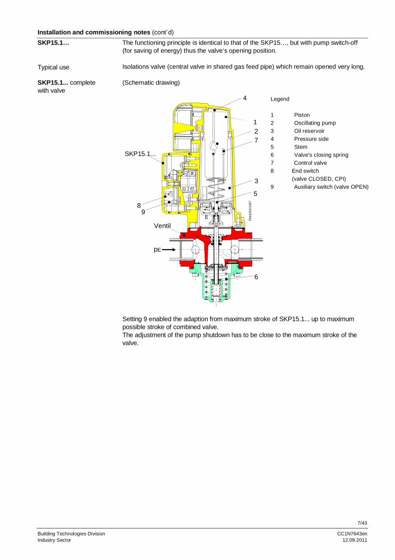
The functioning principle is identical to that of the SKP15…, but with pump switch-off (for saving of energy) thus the valve‘s opening position. Isolations valve (central valve in shared gas feed pipe) which remain opened very long. (Schematic drawing)
7643
z52/
100
7
1
3
4
5
SKP15.1...
2
6
7
Ventil
pE
89
Legend
1 Piston
2 Oscillating pump
3 Oil reservoir
4 Pressure side
5 Stem
6 Valve’s closing spring
7 Control valve
8 End switch
(valve CLOSED, CPI)
9 Auxiliary switch (valve OPEN)
Setting 9 enabled the adaption from maximum stroke of SKP15.1... up to maximum possible stroke of combined valve. The adjustment of the pump shutdown has to be close to the maximum stroke of the valve.
SKP15.1…
Typical use
SKP15.1... complete with valve
8/43
Building Technologies Division CC1N7643en Industry Sector 12.09.2011
Installation and commissioning notes (cont´d)
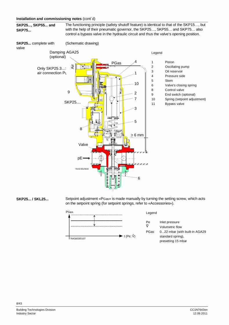
The functioning principle (safety shutoff feature) is identical to that of the SKP15…, but with the help of their pneumatic governor, the SKP25…, SKP55… and SKP75… also control a bypass valve in the hydraulic circuit and thus the valve‘s opening position. (Schematic drawing)
7643z30e/0608
1
2
3
4
5
7
9
10
Air
SKP25....
6
PGas
pE
> 6 mm
Valve
8
Damping AGA25(optional)
Only SKP25.3...:air connection PL
Legend
1 Piston
2 Oscillating pump
3 Oil reservoir
4 Pressure side
5 Stem
6 Valve’s closing spring
8 Control valve
9 End switch (optional)
10 Spring (setpoint adjustment)
11 Bypass valve
Setpoint adjustment «PGas» is made manually by turning the setting screw, which acts on the setpoint spring (for setpoint springs, refer to «Accessories»).
7643d03/0107
PGas
t (Pe; V)
Legend
Pe Inlet pressure V Volumetric flow
PGas 0...22 mbar (with built-in AGA29
standard spring),
presetting 15 mbar
SKP25..., SKP55... and SKP75...
SKP25... complete with valve
SKP25... / SKL25...
9/43
Building Technologies Division CC1N7643en Industry Sector 12.09.2011
Installation and commissioning notes (cont´d)
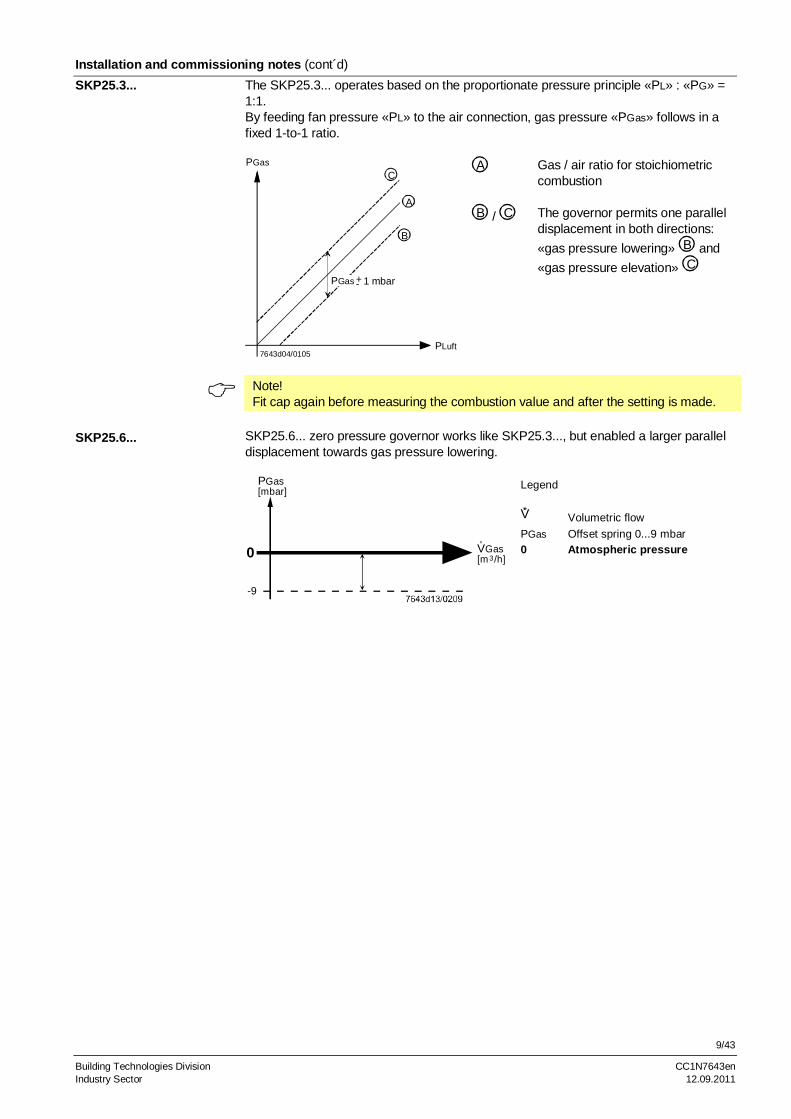
The SKP25.3... operates based on the proportionate pressure principle «PL» : «PG» = 1:1. By feeding fan pressure «PL» to the air connection, gas pressure «PGas» follows in a fixed 1-to-1 ratio.
A Gas / air ratio for stoichiometric combustion
7643d04/0105
CPGas
PLuft
B
A
+- 1 mbarPGas
B / C The governor permits one parallel displacement in both directions:
«gas pressure lowering» B and
«gas pressure elevation» C
Note! Fit cap again before measuring the combustion value and after the setting is made.
SKP25.6... zero pressure governor works like SKP25.3..., but enabled a larger parallel displacement towards gas pressure lowering.
PGas[mbar]
VGas[m /h]3
°
0
-9
Legend
V Volumetric flow
PGas Offset spring 0...9 mbar
0 Atmospheric pressure
SKP25.3...
SKP25.6...
10/43
Building Technologies Division CC1N7643en Industry Sector 12.09.2011
Installation and commissioning notes (cont’d)
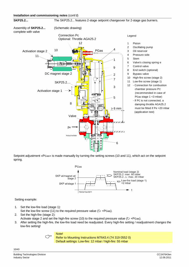
The SKP25.2... features 2-stage setpoint changeover for 2-stage gas burners. (Schematic drawing)
Connection PcOptional: Throttle AGA25.2
7643z37e/0608
1
2
3
4
5
7
9
SKP25.2....
6
PGas
pe
> 6 mm
Valve
8
DC magnet stage 2
11
10
Activation stage 1
12
Activation stage 2
Legend
1 Piston
2 Oscillating pump
3 Oil reservoir
4 Pressure side
5 Stem
6 Valve’s closing spring e
7 Control valve
8 End switch (optional)
9 Bypass valve
10 High-fire screw (stage 2)
11 Low-fire screw (stage 1)
12 - Connection for combustion
chamber pressure PC
(recommended in case of
PGas stage 1 <3 mbar)
- If PC is not connected, a
damping throttle AGA25.2
must be fitted if Pe >20 mbar
(application test)
Setpoint adjustment «PGas» is made manually by turning the setting screws (10 and 11), which act on the setpoint spring.
Setting example: 1. Set the low-fire load (stage 1):
Set the low-fire screw (11) to the required pressure value ( +PGas). 2. Set the high-fire (stage 2):
Activate stage 2 and set the high-fire screw (10) to the required pressure value ( +PGas). 3. After setting the high-fire, the low-fire load need be readjusted. Every high-fire setting / readjustment changes the
Building Technologies Division CC1N7643en Industry Sector 12.09.2011
Installation and commissioning notes (cont´d)
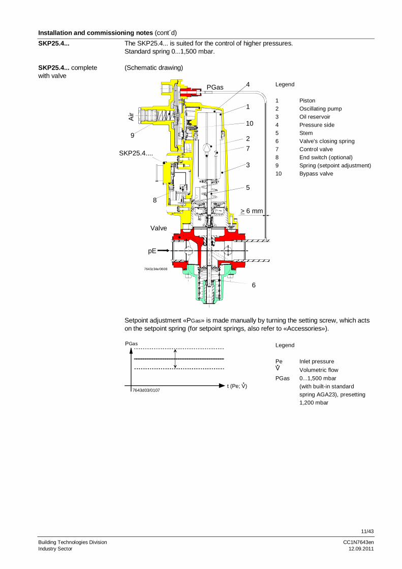
The SKP25.4... is suited for the control of higher pressures. Standard spring 0...1,500 mbar. (Schematic drawing)
7643z34e/0608
1
2
3
4
5
7
10A
ir
SKP25.4....
6
PGas
pE
> 6 mm
Valve
9
8
Legend
1 Piston
2 Oscillating pump
3 Oil reservoir
4 Pressure side
5 Stem
6 Valve’s closing spring
7 Control valve
8 End switch (optional)
9 Spring (setpoint adjustment)
10 Bypass valve
Setpoint adjustment «PGas» is made manually by turning the setting screw, which acts on the setpoint spring (for setpoint springs, also refer to «Accessories»).
7643d03/0107
PGas
t (Pe; V)
Legend
Pe Inlet pressure V Volumetric flow
PGas 0...1,500 mbar
(with built-in standard
spring AGA23), presetting
1,200 mbar
SKP25.4...
SKP25.4... complete with valve
12/43
Building Technologies Division CC1N7643en Industry Sector 12.09.2011
Installation and commissioning notes (cont´d)
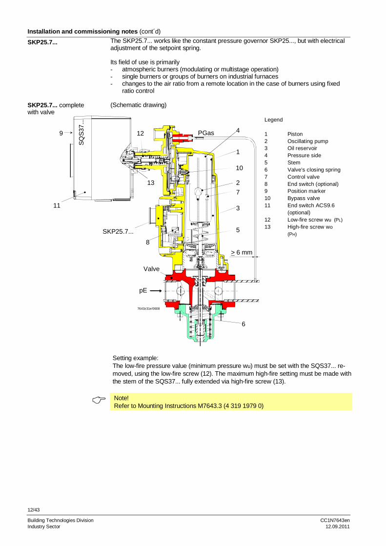
The SKP25.7... works like the constant pressure governor SKP25..., but with electrical adjustment of the setpoint spring. Its field of use is primarily - atmospheric burners (modulating or multistage operation) - single burners or groups of burners on industrial furnaces - changes to the air ratio from a remote location in the case of burners using fixed
ratio control (Schematic drawing)
SQ
S37
...
7643z31e/0608
1
2
3
4
5
7
10
SKP25.7...
6
PGas
pE
> 6 mm
Valve
8
9
11
12
13
Legend 1 Piston 2 Oscillating pump 3 Oil reservoir 4 Pressure side 5 Stem 6 Valve’s closing spring 7 Control valve 8 End switch (optional) 9 Position marker 10 Bypass valve 11 End switch ACS9.6 (optional) 12 Low-fire screw wu (PL) 13 High-fire screw wo
(PH)
Setting example: The low-fire pressure value (minimum pressure wu) must be set with the SQS37... re-moved, using the low-fire screw (12). The maximum high-fire setting must be made with the stem of the SQS37... fully extended via high-fire screw (13).
Note! Refer to Mounting Instructions M7643.3 (4 319 1979 0)
SKP25.7...
SKP25.7... complete with valve
13/43
Building Technologies Division CC1N7643en Industry Sector 12.09.2011
Installation and commissioning notes (cont´d)
t7643d05/0907
t
pa
Wom
Wu
Wo
Wo
Wu
Wo Wo
Wom
tt
(PH)
(PL)
On the gas outlet side, the gas pressure governor maintains the pressure at the required setpoint. The electrical signal fed to the SQS37... changes the pread-justed setpoint in proportion to the length of the electrical pulse, either increasing or decreasing, depending on the direc-tion of the pulse signal. When the preset maximum or minimum setpoint is reached, the outlet pressure will remain at a constant level. The time required to traverse the upper setpoint range «wo» is the same in both directions. Running time «two» changes in proportion to the change of the upper setpoint range «wo». At the lower setpoint limitation «wu», the SQS37... runs idle during the period of time «two», which means that a certain part of it can occur as dead time.
pa Outlet pressure wo Upper setpoint limitation wu Lower setpoint limitation wo Upper setpoint range, adjustable wom Max. possible upper setpoint range wu Lower setpoint limitation range, adjustable two Dead time two Running time accordant of setpoint range two
t wo = t womwowom
twom Running time with max. setpoint range wom Delivery ex works for the following setpoint ranges: wu 0.5...4 mbar 15 % wo 0...18 mbar 15 % For springs required for other pressure ranges, please refer to the following table. Setpoint ranges other than the standard range can be selected by changing the springs. Each SKP25.7... is supplied with 9 additional springs in a plastic bag, which can be fitted on site, if required.
Spring wu Spring wo Color Dia. mm mbar 15 % Color Dia. mm mbar 15 %
Steel-colored * 12 0.5...4 White 7 0...10
Green 12.5 2...15 Steel-colored * 7 0...18 Yellow 12.5 15...120 Red 7.5 0...45 Blue 13 10...30 Green 8 0...90 Red 13 100...250
* The steel-colored springs are fitted in the SKP25.7... Setpoint springs for «wo» cannot be used for «wu», and vice versa (refer to spring dia. in the table). All combinations of «wo» and «wu» are possible.
Functioning principle of gas pressure governor with SQS37... motorized setpoint adjuster:
Legend
Setpoint springs for SKP25.7...
14/43
Building Technologies Division CC1N7643en Industry Sector 12.09.2011
Installation and commissioning notes (cont´d)
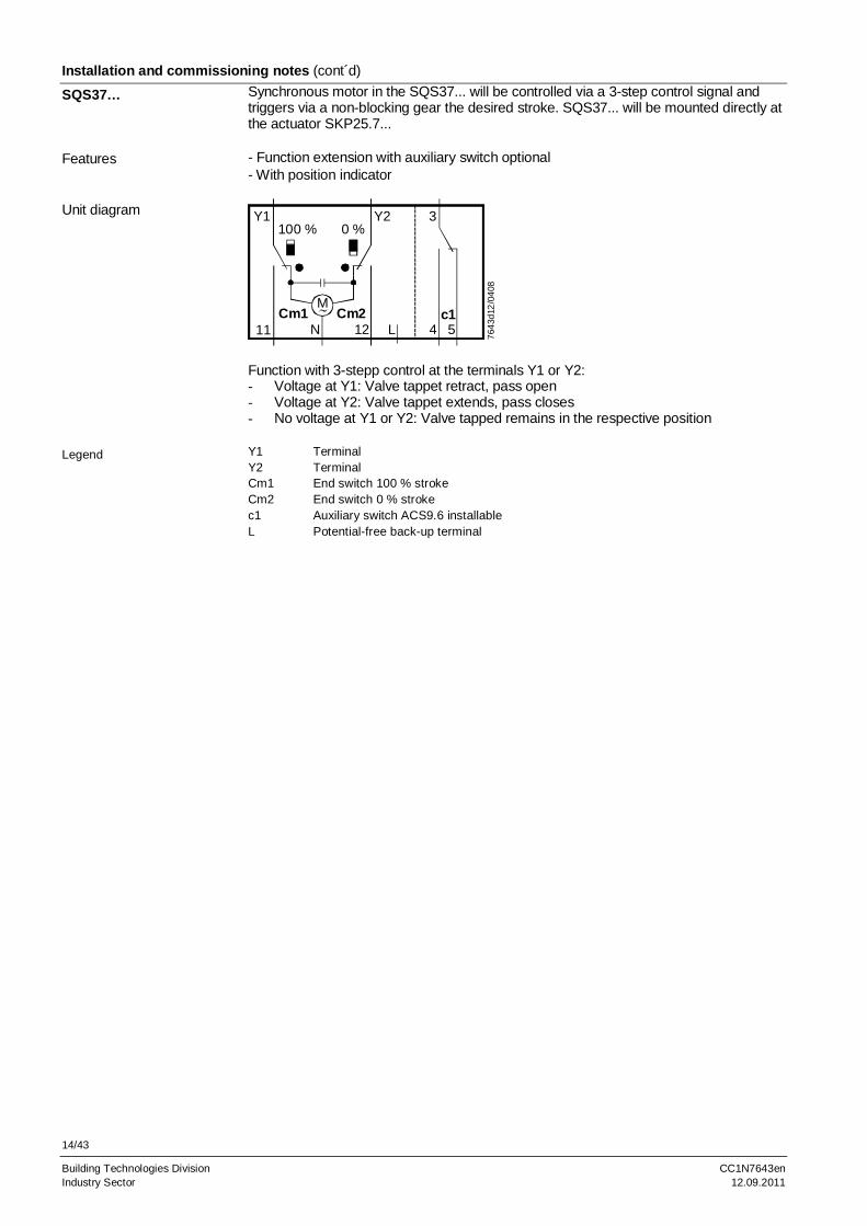
Synchronous motor in the SQS37... will be controlled via a 3-step control signal and triggers via a non-blocking gear the desired stroke. SQS37... will be mounted directly at the actuator SKP25.7... - Function extension with auxiliary switch optional - With position indicator
764
3d12
/04
08
Y1100 % 0 %
Y2 3
c154L12
Cm2M
NCm1
11
Function with 3-stepp control at the terminals Y1 or Y2: - Voltage at Y1: Valve tappet retract, pass open - Voltage at Y2: Valve tappet extends, pass closes - No voltage at Y1 or Y2: Valve tapped remains in the respective position Y1 Terminal Y2 Terminal Cm1 End switch 100 % stroke Cm2 End switch 0 % stroke c1 Auxiliary switch ACS9.6 installable L Potential-free back-up terminal
SQS37…
Features
Unit diagram
Legend
15/43
Building Technologies Division CC1N7643en Industry Sector 12.09.2011
Installation and commissioning notes (cont´d)
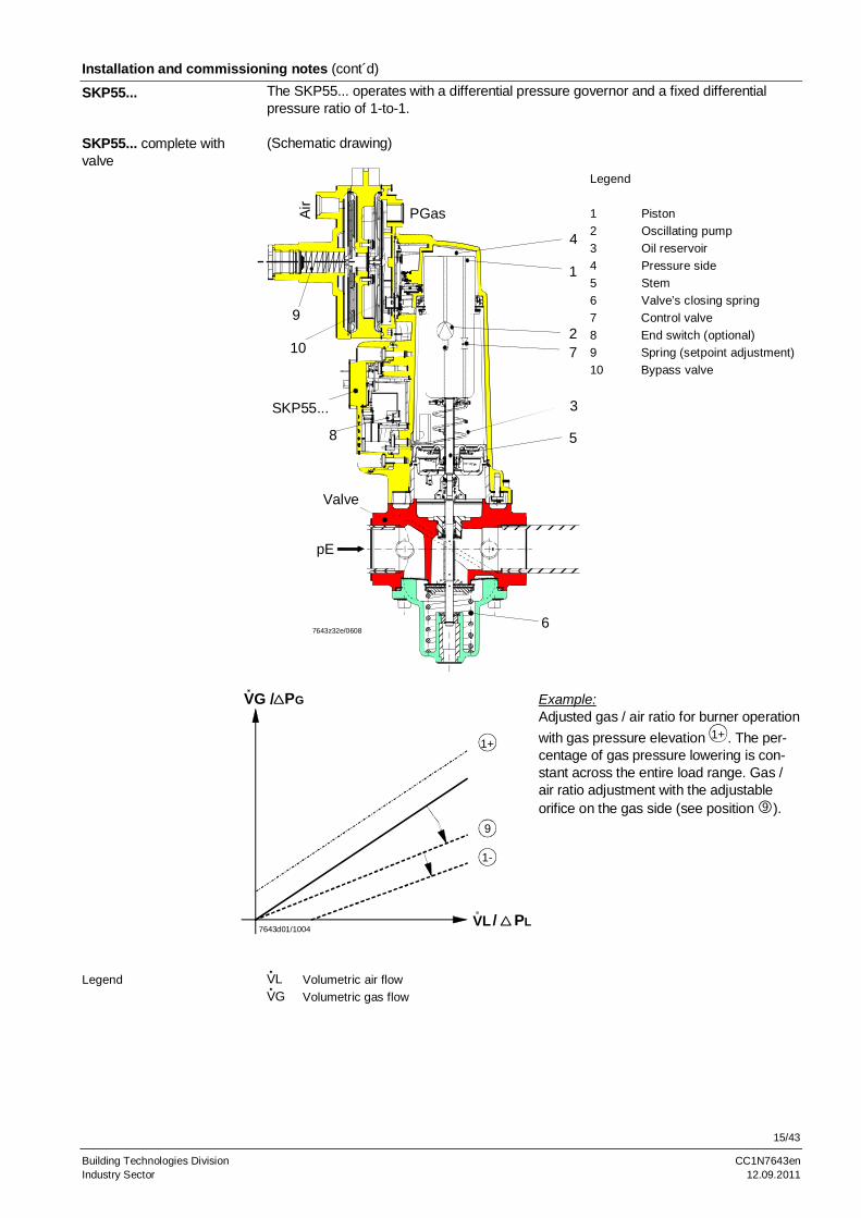
The SKP55... operates with a differential pressure governor and a fixed differential pressure ratio of 1-to-1. (Schematic drawing)
1
2
3
5
7
Air
SKP55...
4
PGas
7643z32e/06086
pE
Valve
8
9
10
Legend
1 Piston
2 Oscillating pump
3 Oil reservoir
4 Pressure side
5 Stem
6 Valve’s closing spring
7 Control valve
8 End switch (optional)
9 Spring (setpoint adjustment)
10 Bypass valve
9
1-
7643d01/1004
VG /
VL
1+
PG
/ PL
Example: Adjusted gas / air ratio for burner operation
with gas pressure elevation 1+ . The per-centage of gas pressure lowering is con-stant across the entire load range. Gas / air ratio adjustment with the adjustable orifice on the gas side (see position ).
VL Volumetric air flow
VG Volumetric gas flow
SKP55...
SKP55... complete with valve
Legend
16/43
Building Technologies Division CC1N7643en Industry Sector 12.09.2011
Installation and commissioning notes (cont´d)
pL AM
+-3 2SKP55.../V...
1 +
-
4-5 +
pG
7643
z01e
/12
04
B B
Air
Gas
VG
11VL
7
8
9
10
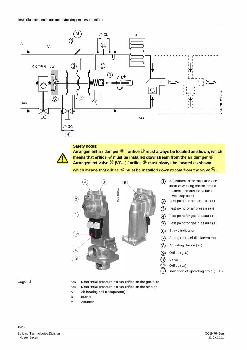
Safety notes: Arrangement air damper / orifice 11 must always be located as shown, which
means that orifice 11 must be installed downstream from the air damper . Arrangement valve 10 (VG...) / orifice must always be located as shown,
which means that orifice must be installed downstream from the valve 10 .
Adjustment of parallel displace-
ment of working characteristic
* Check combustion values
with cap fitted
Test point for air pressure (+)
Test point for air pressure (-)
Test point for gas pressure (-)
Test point for gas pressure (+)
Stroke indication
Spring (parallel displacement)
Actuating device (air)
Orifice (gas)
10 Valve 11 Orifice (air)
1
2
34
10
7643
z12/
120
4
5
6
12
12 Indication of operating state (LED) pG Differential pressure across orifice on the gas side
pL Differential pressure across orifice on the air side
A Air heating coil (recuperator)
B Burner
M Actuator
Legend
17/43
Building Technologies Division CC1N7643en Industry Sector 12.09.2011
Installation and commissioning notes (cont´d)
Adjustment of governor on modulating burners prior to startup:
- Setting screw on the SKP55... should be set to a gas / air ratio curve which passes through the neutral point. The SKP55... is supplied with that factory set-ting. Adjustment in the field can be made as follows:
Note: Fit cap again before measuring the combustion value and after the setting is made. Turn setting screw in counterclockwise direction until spring is com-pletely loose. Shut off the gas supply upstream of the SKP55... Switch on the SKP55... Turn setting screw in clockwise direction until valve opens
- Bring the adjustable orifice to the precalculated value. That value with the same pressure differential on the air and gas side must lead to practically stoichiometric combustion
- Start the burner and run it to about 90 % of the high-fire - Measure the combustion quality and make adjustments of the flow rate with the
adjustable orifice until optimum measured values are reached (fine adjust-ment)
- Return to low-fire operation. Check the combustion and readjust if necessary the position of the working characteristic with the setting screw on the SKP55... until optimum measured values are reached. Clockwise rotation more gas. Counterclockwise rotation less gas, that is, parallel displacement of the working characteristic towards gas pressure elevation or gas pressure lowering
- Limit the air damper for low-fire operation - If a significant parallel displacement of the working characteristic was required,
the setting must be checked again at 90 % of the high-fire and then readjusted, if required
- Run the burner to the predefined high-fire with the help of the air damper and limit the actuator position for that load
- Check the flue gas values at a few positions of the load range. Make readjust-ments in the high-fire range with the adjustable orifice , and in the low-fire range with setting screw on the governor of the SKP55...
SKP55…
18/43
Building Technologies Division CC1N7643en Industry Sector 12.09.2011
Installation and commissioning notes (cont´d)
The SKP75... operates with a ratio pressure governor and an adjustable gas / air ratio. (Schematic drawing)
7643z33e/0407
1
2
3
9
5
6
7
8
Air
PGas
SKP75...
pE
> 6 mm
min. 5d
Valve
4
Legend
1 Piston
2 Oscillating pump
3 Oil reservoir
4 Pressure side
5 Stem
6 Valves closing spring
7 Control valve
8 End switch (optional)
9 Bypass valve
Use setting screw / «PGAS» / «PAIR» to set the gas / air ratio to the required
value (coarse setting) and the scale with setting screw to zero (refer to Fig. 7643z03)
Start the burner and run it to about 90 % of the high-fire Measure the CO2 or O2 content of the flue gases and optimize the adjustment with
setting screw / «PGAS» / «PAIR» (refer to Fig. 7643z03) Return to low-fire operation, check the CO2 or O2 content of the flue gases. If nec-
essary, readjust position of the working characteristic with setting screw / until optimum measured values are attained
Limit the air damper position for low-fire operation Meaning of setting screw markings: + More gas
- Less gas
SKP75...
SKP75... complete with valve
Adjustment of governor on modulating burners
19/43
Building Technologies Division CC1N7643en Industry Sector 12.09.2011
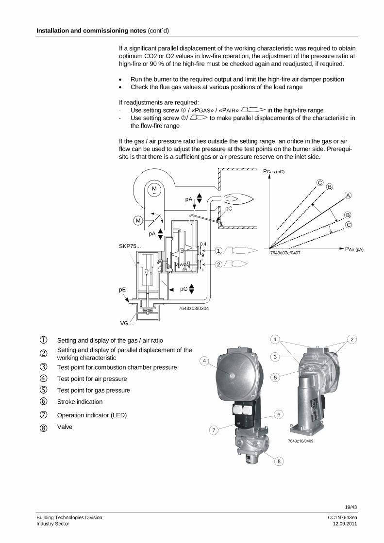
Installation and commissioning notes (cont´d)
If a significant parallel displacement of the working characteristic was required to obtain optimum CO2 or O2 values in low-fire operation, the adjustment of the pressure ratio at high-fire or 90 % of the high-fire must be checked again and readjusted, if required. Run the burner to the required output and limit the high-fire air damper position Check the flue gas values at various positions of the load range If readjustments are required: - Use setting screw / «PGAS» / «PAIR» in the high-fire range - Use setting screw / to make parallel displacements of the characteristic in
the flow-fire range If the gas / air pressure ratio lies outside the setting range, an orifice in the gas or air flow can be used to adjust the pressure at the test points on the burner side. Prerequi-site is that there is a sufficient gas or air pressure reserve on the inlet side.
M
M~
0,4
9-
+
7643z03/0304
1
2
pA
pC
pGpE
SKP75...
VG...
pA
A
BC
PGas (pG)
PAir (pA)
B
C
7643d07e/0407
Setting and display of the gas / air ratio
Setting and display of parallel displacement of the working characteristic
Test point for combustion chamber pressure
Test point for air pressure
Test point for gas pressure
Stroke indication
Operation indicator (LED)
Valve
1 2
34
5
6
7
8
20/43
Building Technologies Division CC1N7643en Industry Sector 12.09.2011
Installation and commissioning notes (cont´d)
If the air pressure (fan pressure) exceeds the maximum value of
30 mbar with a PGas / PAir ratio of 2 50 mbar with a PGas / PAir ratio of 2
permitted for the governor, the pressure must be lowered with a reducing T-piece AGA78 (also refer to «Technical data»).
10 20 3010
20
30
40
50
60
70
80
90
P1
P2
D1 = 1,5 mm; D
2 = 2 mm
D1 = 1,5 mm; D2 = 1,7 mm
7643
d02/
0503
100
110
120
130
Example: p1 = 70 mbar D1 = 1.5 mm D2 = 1.7 mm Wanted: Air pressure signal «p2» for SKP75... p2 = 26 mbar
Air is continuously vented to atmosphere via orifice «D2». The pressure of the following medium will be reduced via throttle «D1». The illustration below shows the correlations.
The reducing T-piece AGA78 is supplied ready for mounting, with D1 = 1.5 mm and D2 = 1.7 mm. D2 with a diameter of 2 mm is included as a loose item.
Function
21/43
Building Technologies Division CC1N7643en Industry Sector 12.09.2011
Standards and certificates
ISO 9001: 2010 Cert. 00739
ISO 14001: 2010 Cert. 38233
For use in the U.S. / Canada, the actuators carry type suffix «U» (see example) and are , and -listed (Example: SKP25.003U1, refer to separate Data Sheet [on request]).
Conformity to EEC directives – Electromagnetic compatibility EMC (immunity) – Directive for gas appliances – Directive for pressure devices
2004/108/EC 2009/142/EC 97/23/EC
Life cycle
The combination valve and actuator have a designed lifetime* of Nominal size Burner startup cycles 25 DN 200.000 25...80 DN 100.000 80...150 DN 50.000 which, under use of gases to EN437 (or DVGW specification G260). This lifetime is based on the endurance tests specified in standard EN161 and the table containing the relevant test documentation as published by the European Association of Component Manufacturers (Afecor) (www.afecor.org). The designed lifetime is based on use of the valve and actuator according to the manu-facturer’s Data Sheet. When reaching the designed lifetime in terms of the number of burner startup cycles or the respective time of usage, valve and actuator must be checked by authorized personnel and, if necessary, replaced. * The designed lifetime is not the warranty time specified in the Terms of Delivery.
Disposal notes
The actuator contains electrical and electronic components and hydraulic oil and must not be disposed of together with domestic waste. Local and currently valid legislation must be observed.
In combination with valves
22/43
Building Technologies Division CC1N7643en Industry Sector 12.09.2011
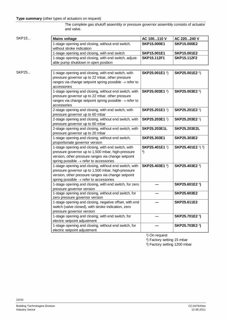
Type summary (other types of actuators on request)
The complete gas shutoff assembly or pressure governor assembly consists of actuator and valve.
Mains voltage AC 100...110 V AC 220...240 V 1-stage opening and closing, without end switch, without stroke indication
SKP15.000E1 SKP15.000E2
1-stage opening and closing, with end switch SKP15.001E1 SKP15.001E2 1-stage opening and closing, with end switch, adjust-able pump shutdown in open position
SKP15.112F1 SKP15.112F2
1-stage opening and closing, with end switch, with pressure governor up to 22 mbar, other pressure ranges via change setpoint spring possible refer to accessories
SKP25.001E1 ²) SKP25.001E2 ²)
1-stage opening and closing, without end switch, with pressure governor up to 22 mbar, other pressure ranges via change setpoint spring possible refer to accessories
SKP25.003E1 ²) SKP25.003E2 ²)
2-stage opening and closing, with end switch, with pressure governor up to 60 mbar
SKP25.201E1 ¹) SKP25.201E2 ¹)
2-stage opening and closing, without end switch, with pressure governor up to 60 mbar
SKP25.203E1 ¹) SKP25.203E2 ¹)
2-stage opening and closing, without end switch, with pressure governor up to 20 mbar
SKP25.203E1L SKP25.203E2L
1-stage opening and closing, without end switch, proportionate governor version
SKP25.303E1 SKP25.303E2
1-stage opening and closing, with end switch, with pressure governor up to 1,500 mbar, high-pressure version, other pressure ranges via change setpoint spring possible refer to accessories
SKP25.401E1 ¹) ³)
SKP25.401E2 ¹) ³)
1-stage opening and closing, without end switch, with pressure governor up to 1,500 mbar, high-pressure version, other pressure ranges via change setpoint spring possible refer to accessories
SKP25.403E1 ³) SKP25.403E2 ³)
1-stage opening and closing, with end switch, for zero pressure governor version
--- SKP25.601E2 ¹)
1-stage opening and closing, without end switch, for zero pressure governor version
--- SKP25.603E2
1-stage opening and closing, negative offset, with end switch (valve closed), with stroke indication, zero pressure governor version
--- SKP25.611E2
1-stage opening and closing, with end switch, for electric setpoint adjustment
--- SKP25.701E2 ¹)
1-stage opening and closing, without end switch, for electric setpoint adjustment
Building Technologies Division CC1N7643en Industry Sector 12.09.2011
Type summary (other types of actuators on request)
1-stage opening and closing, with end switch, with pressure governor up to 22 mbar, other pressure ranges via change setpoint spring possible refer to accessories
SKL25.001E1 ²) SKL25.001E2 ²)
1-stage opening and closing, without end switch, with pressure governor up to 22 mbar, other pressure ranges via change setpoint spring possible refer to accessories
SKL25.003E1 SKL25.003E2 ²)
1-stage opening and closing, with end switch, with differential pressure governor
SKP55.001E1 SKP55.001E2
1-stage opening and closing, without end switch, with differential pressure governor
SKP55.003E1 SKP55.003E2
1-stage opening and closing, with end switch, with ratio pressure governor
SKP75.001E1 SKP75.001E2
1-stage opening and closing, without end switch, with ratio pressure governor
SKP75.003E1 SKP75.003E2
1-stage opening and closing, with end switch, with ratio pressure governor, with greater parallel dis-placement
SKP75.501E1 SKP75.501E2
1-stage opening and closing, without end switch, with ratio pressure governor, with greater parallel dis-placement
SKP75.503E1 SKP75.503E2
²) Factory setting 15 mbar
Ordering examples
When ordering, please give the complete type reference of the actuator (refer to «Type summary»). All components must be ordered as separate items. Actuator with safety shutoff function - Open / closed - With end switch - For AC 230 V / 50 Hz
SKP15.001E2
Connector valve actuator (plug) AGA64 Connector end switch (plug) AGA65 Combination of actuator / valve consisting of: - Valve - SKP15.001E2 actuator - Accessories Please order the required valves as separate items (refer to the relevant Data Sheets). Actuator and valve are supplied unassembled. Assembly is very straightforward and preferably made on the burner. Gas pressure governor with safety shutoff function: - Without end switch - For AC 230 V / 50 Hz
SKP25.003E2
Connector valve actuator (plug) AGA64 Combination of gas pressure governor / valve consisting of: - Valve - SKP25.003E2 actuator - Accessories, e.g. AGA25 (damping throttle)
SKL25...
SKP55...
SKP75...
Example of SKP15...
Example of SKP25...
24/43
Building Technologies Division CC1N7643en Industry Sector 12.09.2011
Accessories (not supplied as standard, to be ordered as separate items)
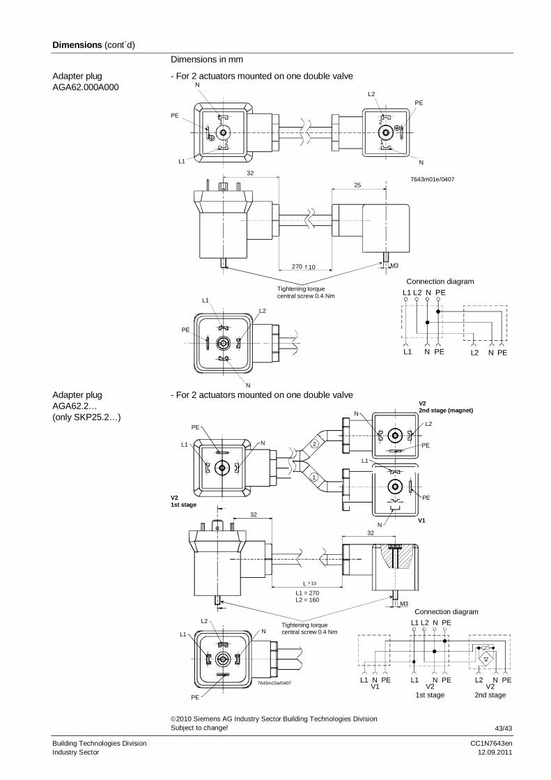
Adapter plug AGA62.000A000- For powering both actuators on the double valve VGD... via plug (AGA64) Example: SKP15... / SKP25.2... with adapter plug AGA62.000A000
V1 V2
7643
z49
e/04
07
Central connection via AGA64for the separate controlof valves 1 and valves 2Facilitates valve proovingvia pressure switch between thevalves or ignition via pilot burner
Adapter plug for SKP25.2… AGA62.2- For powering both actuators and the magnet (stage 2) via plug (AGA64) Both valves are activated simultaneously - Including rectifier for DC coil (activation stage 2) Example: SKP15... / SKP25.2... with adapter plug AGA62.2
Stage 2 (DC coil)
Central connection via AGA64for the common controlof valves 1 and valves 2
764
3z4
1e/0
407
V1 V2
Integrated rectifier
25/43
Building Technologies Division CC1N7643en Industry Sector 12.09.2011
Accessories (not supplied as standard, to be ordered as separate items) (cont´d)
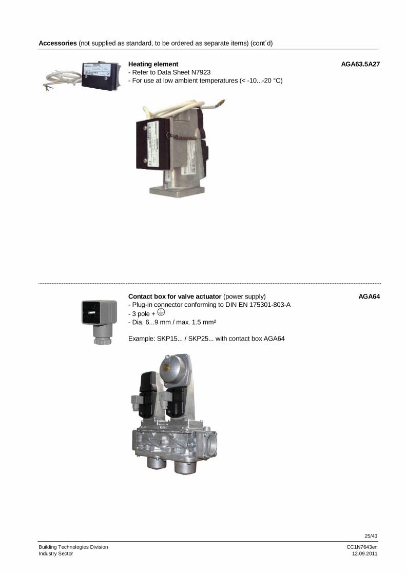
Heating element AGA63.5A27- Refer to Data Sheet N7923 - For use at low ambient temperatures (< -10...-20 °C)
Contact box for valve actuator (power supply) AGA64- Plug-in connector conforming to DIN EN 175301-803-A - 3 pole + - Dia. 6...9 mm / max. 1.5 mm² Example: SKP15... / SKP25... with contact box AGA64
26/43
Building Technologies Division CC1N7643en Industry Sector 12.09.2011
Accessories (not supplied as standard, to be ordered as separate items) (cont´d)
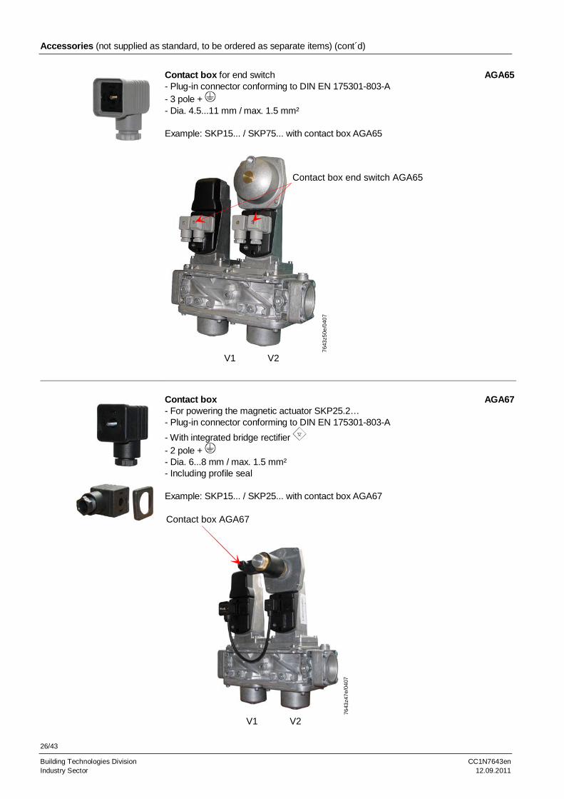
Contact box for end switch AGA65- Plug-in connector conforming to DIN EN 175301-803-A - 3 pole + - Dia. 4.5...11 mm / max. 1.5 mm² Example: SKP15... / SKP75... with contact box AGA65
Contact box end switch AGA65
764
3z5
0e/0
407
V1 V2
Contact box AGA67- For powering the magnetic actuator SKP25.2… - Plug-in connector conforming to DIN EN 175301-803-A
- With integrated bridge rectifier
- 2 pole + - Dia. 6...8 mm / max. 1.5 mm² - Including profile seal Example: SKP15... / SKP25... with contact box AGA67
Contact box AGA67
7643
z47
e/04
07
V1 V2
27/43
Building Technologies Division CC1N7643en Industry Sector 12.09.2011
Accessories (not supplied as standard, to be ordered as separate items) (cont´d)
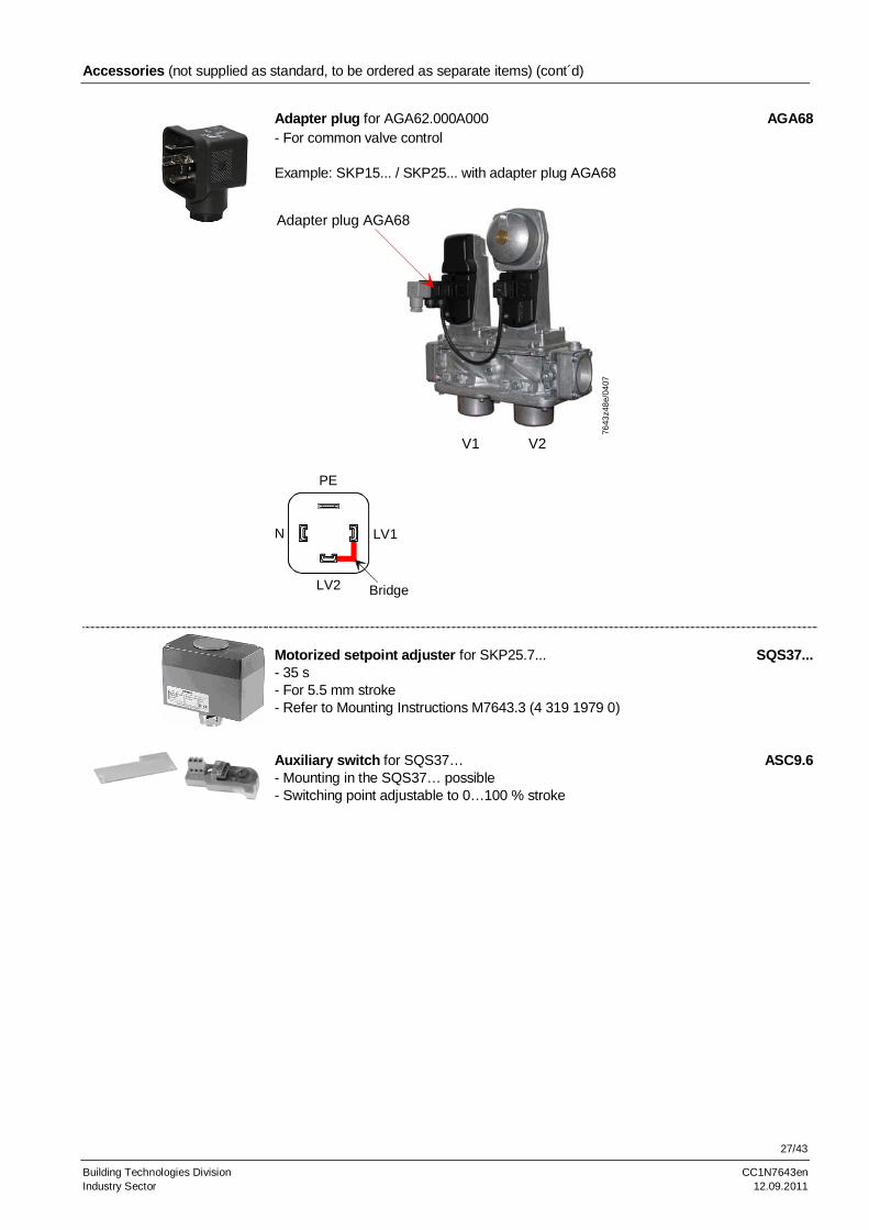
Adapter plug for AGA62.000A000 AGA68- For common valve control Example: SKP15... / SKP25... with adapter plug AGA68
Adapter plug AGA68
7643
z48
e/04
07
V1 V2
LV2
N
PE
LV1
Bridge
Motorized setpoint adjuster for SKP25.7... SQS37...- 35 s - For 5.5 mm stroke - Refer to Mounting Instructions M7643.3 (4 319 1979 0) Auxiliary switch for SQS37… ASC9.6- Mounting in the SQS37… possible - Switching point adjustable to 0…100 % stroke
28/43
Building Technologies Division CC1N7643en Industry Sector 12.09.2011
Accessories (not supplied as standard, to be ordered as separate items) (cont´d)
Setpoint spring (blank) for SKP25.2...L AGA17- Equivalent built-in standard spring - 2...20 mbar Setpoint spring (yellow) for SKP25... AGA22- Optional for built-in standard spring AGA29 - 15...120 mbar at SKP25.0… - 70…700 mbar at SKP25.4... (optional for AGA23) Setpoint spring (red) for SKP25... AGA23- Optional for built-in standard spring AGA29 - 100...250 mbar at SKP25.0… - 150...1,500 mbar at standard spring SKP25.4... Setpoint spring (blank) for SKP25.3... AGA28- Equivalent built-in standard spring - ±1.5 mbar
Setpoint spring (blank) for SKP25.0... AGA29- Equivalent built-in standard spring - 0,5...22 mbar
Damping throttle for SKP25.0... and SKP25.3... AGA25- Optional
Damping throttle for SKP25.2... AGA25.2- Optional
Damping throttle for SKP55.../SKP75... AGA75- Optional, pipe connection for 8 mm dia. - Refer to Mounting Instructions 4 319 2078 0
Damping throttle for SKP55.../SKP75... AGA75E- Optional (same as damping throttle AGA75 but with ¼“ threaded connection on both sides) - Refer to Mounting Instructions 4 319 9601 0
Pressure reducing-T-piece for SKP75... AGA78- Optional
29/43
Building Technologies Division CC1N7643en Industry Sector 12.09.2011
Accessories (not supplied as standard, to be ordered as separate items) (cont´d)
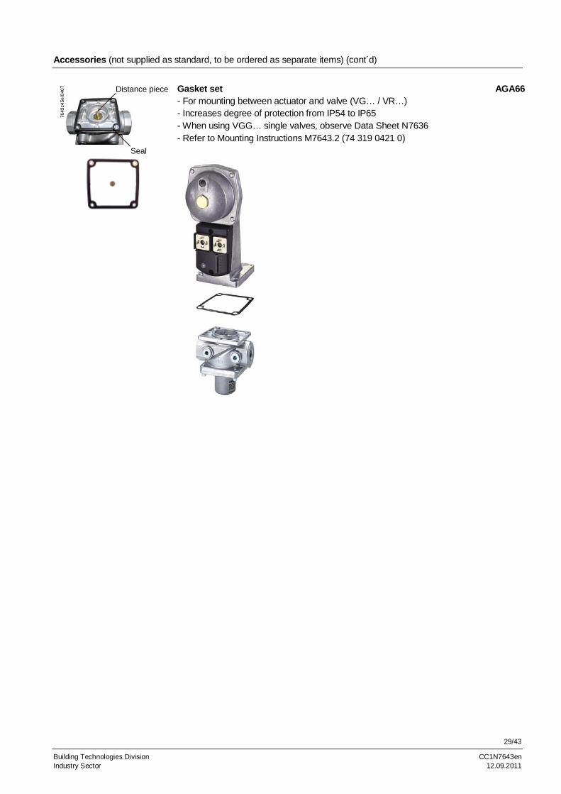
Distance piece
Seal
7643
z45e
/040
7
Gasket set AGA66- For mounting between actuator and valve (VG… / VR…) - Increases degree of protection from IP54 to IP65 - When using VGG… single valves, observe Data Sheet N7636 - Refer to Mounting Instructions M7643.2 (74 319 0421 0)
30/43
Building Technologies Division CC1N7643en Industry Sector 12.09.2011
Technical Data
Mains voltage AC 220 V –15 %...AC 240 V +10 % AC 100 V –15 %...AC 110 V +10 %
Mains frequency 50...60 Hz 6 % Power consumption - SKPx5... Max. 13.5 VA - SKP15.1... Max. 13.5...23 VA
Max. 3 VA (in open position) - SKP25.2... Max. 38 VA Closing time - SKPx5…
<0.8 s (at shutdown)
- SKL25… 3…6 s (depending on the type of valve) Required time interval load change carried via air / fuel ration pressure between high-fire and low-fire
- SKP25.3... / SKP55... / SKP75... Min. 4 s (depending on valve stroke) Opening time for full stroke 6...13 s (depending on valve nominal size)
(longer opening times below 0 °C) Degree of protection - SKPx5... IP54
only ensured when central screw at the connector is tightened IP65 only with gasket kit AGA66
- SKP25... / SKP55... only with screwed-on locking caps Control class A to DIN EN 88-1 Control accuracy - SKP25.3... / SKP75... <10 % at «pmin», <2 % at «pmax» - SKP55... <10 % at «pmin», <1 % at «pmax» Inlet pressure Like valve Control variable gas pressure - SKP25... / SKL25... 0.5...250 mbar (3 setpoint springs) - SKP25.2... 2...60 mbar - SKP25.2...L 2...20 mbar - SKP25.3... 0.5...50 mbar - SKP25.4... 70...1500 mbar (2 setpoint springs) - SKP25.6... <0 mbar (atmosphere) - SKP25.7... Refer to table in chapter Installation and
commissioning notes «Setpoint springs for SKP25.7...»
- Switching load 4 (2 A, cos = 0.3) On-time 100 % Opening speed (approx.. 2 mm/s) Lower opening speeds due to low ambient
temperatures can be compensated by fitting an AGA63.5A27 heating element
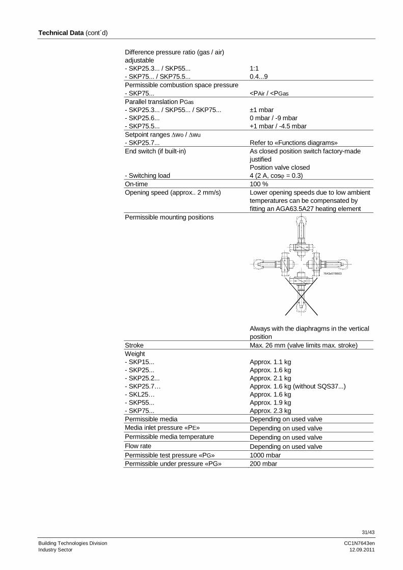
Permissible mounting positions
7643z07/0603
Always with the diaphragms in the vertical position
Stroke Max. 26 mm (valve limits max. stroke) Weight - SKP15... Approx. 1.1 kg - SKP25... Approx. 1.6 kg - SKP25.2... Approx. 2.1 kg - SKP25.7… Approx. 1.6 kg (without SQS37...) - SKL25… Approx. 1.6 kg - SKP55... Approx. 1.9 kg - SKP75... Approx. 2.3 kg Permissible media Depending on used valve Media inlet pressure «PE» Depending on used valve Permissible media temperature Depending on used valve Flow rate Depending on used valve Permissible test pressure «PG» 1000 mbar Permissible under pressure «PG» 200 mbar
32/43
Building Technologies Division CC1N7643en Industry Sector 12.09.2011
Technical data (cont´d)
Storage DIN EN 60721-3-1 Climatic conditions Class 1K3 Mechanical conditions Class 1M2 Temperature range -15...+60 °C Humidity <95 % r.h. Transport DIN EN 60721-3-2 Climatic conditions Class 2K2 Mechanical conditions Class 2M2 Temperature range -15...+60 °C Humidity <95 % r.h. Operation DIN EN 60721-3-3 Climatic conditions Class 3K3 Mechanical conditions Class 3M3 Temperature range -10...+60 °C
(longer opening times below 0 °C) -20…+60 °C (with heating element AGA63.5)
- SKP25.7... -5…+50 °C (limited by SQS37...)
Humidity <95 % r.F. Mains voltage (control voltage) AC 230 V +10 % / -15 % Mains frequency 50...60 Hz ±6 % Power consumption 2.5 VA Running time twom 5.5 mm / 35 s Degree of protection IP54 Safety class II VDE 0631
Environmental conditions Vmax environment 50 °C Control signal 3-step
Regulating power 400 N
Stroke 5.5 mm Switching capacity AC 250 V
3 A 3 A inductive
Environmental conditions
Motorized setpoint adjuster SQS37...
Auxiliary switch ASC9.6
33/43
Building Technologies Division CC1N7643en Industry Sector 12.09.2011
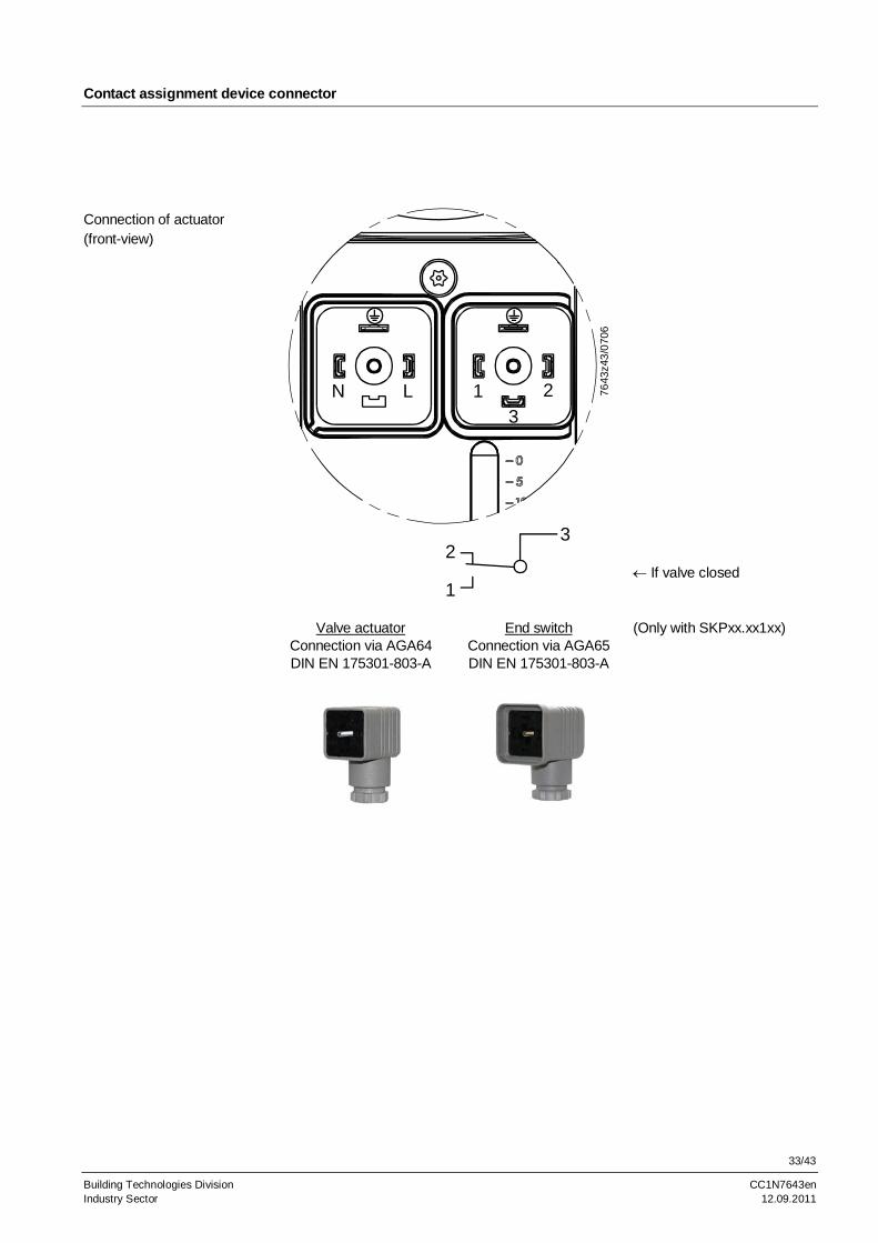
Contact assignment device connector
7643
z43
/070
6
N L 1 2
3
1
23
If valve closed
Valve actuator
Connection via AGA64 DIN EN 175301-803-A
End switch Connection via AGA65 DIN EN 175301-803-A
(Only with SKPxx.xx1xx)
Connection of actuator (front-view)
34/43
Building Technologies Division CC1N7643en Industry Sector 12.09.2011
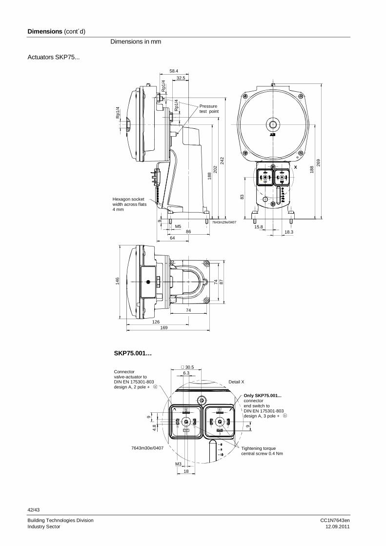
Dimensions
Dimensions in mm Example: SKP15.000…
7643
m1
8e/
040
7
9
M5
188
83
74 87
15.818.3
7486
64
Hexagon socketwidth across flats4 mm
SKP15.000… (no stroke indication) SKP15.001…
30.5
9
Connectorvalve-actuator toDIN EN 175301-803design A, 2 pole +
Detail X
M3
18Tightening torquecentral screw 0.4 Nm
7643m16e/0407
6.3
30.5
Connector end switchto DIN EN 175301-803design A, 3 pole +
9
Connectorvalve-actuator toDIN EN 175301-803design A, 2 pole +
Detail X
M318
Tightening torquecentral screw 0.4 Nm
7643m17e/0407
6.3
Actuators SKP15...
35/43
Building Technologies Division CC1N7643en Industry Sector 12.09.2011
Dimensions (cont´d)
Dimensions in mm
Earthing terminal
55
86M5
9
Hexagon socketwidth across flats4 mm
74
87
74
81
124
80
97
18
8
M2
0 x
1,5
-9
tie
f
7643
m33
e/06
08 X
Cable entry point
Detail X
7643m35e/0608
Actuator SKP15.1...
36/43
Building Technologies Division CC1N7643en Industry Sector 12.09.2011
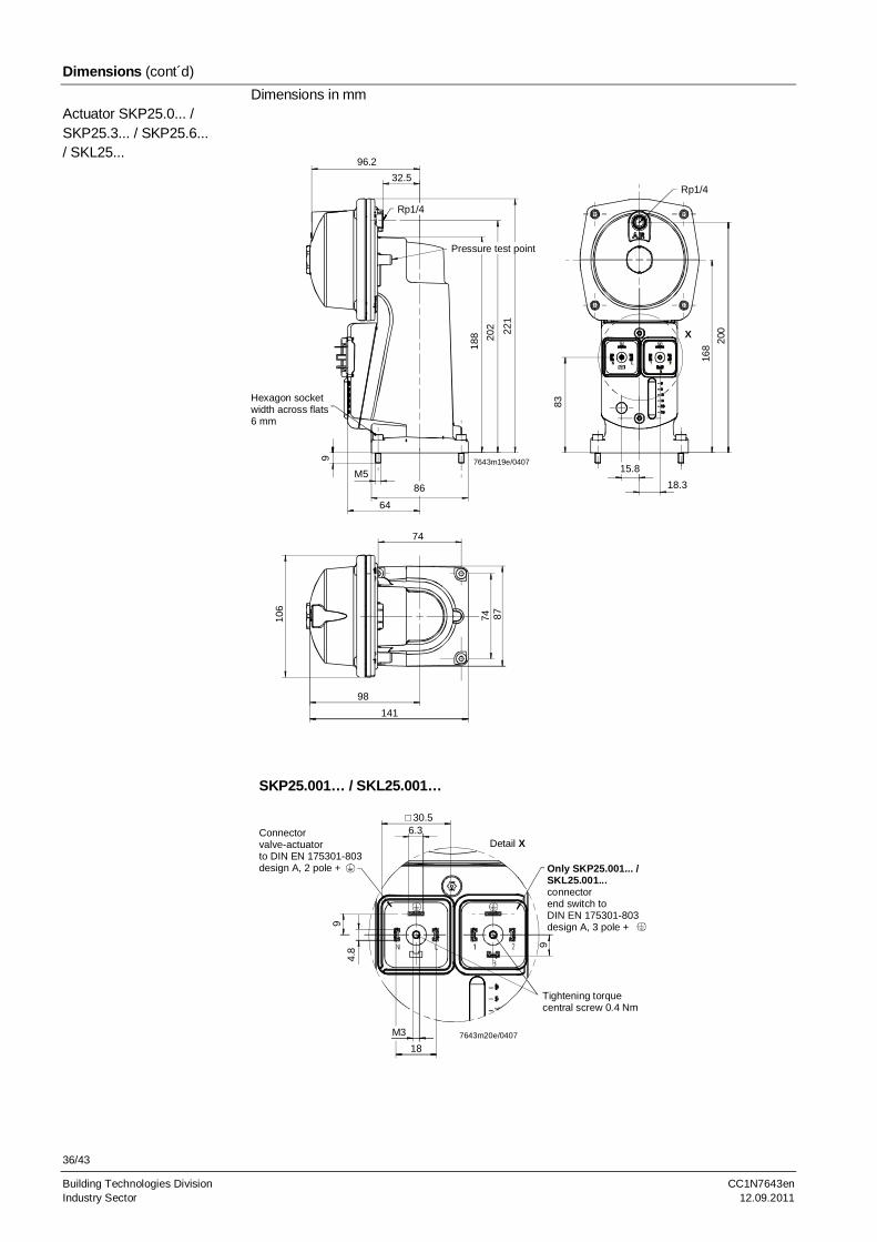
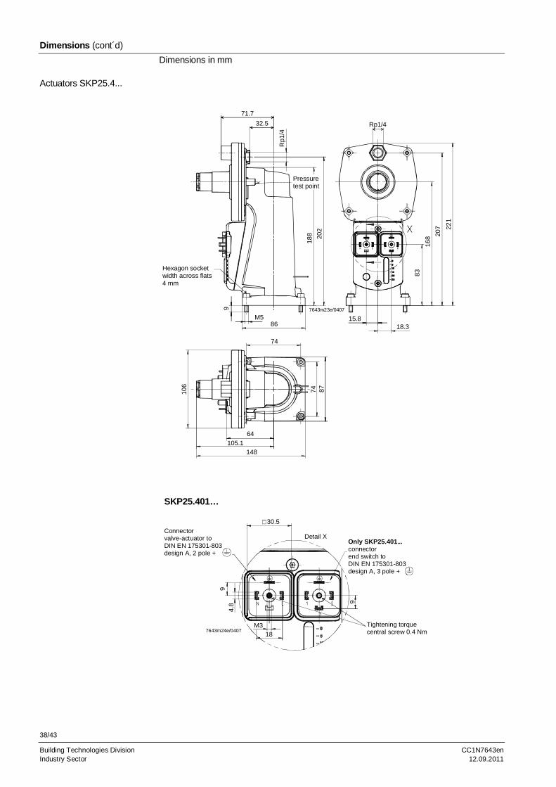
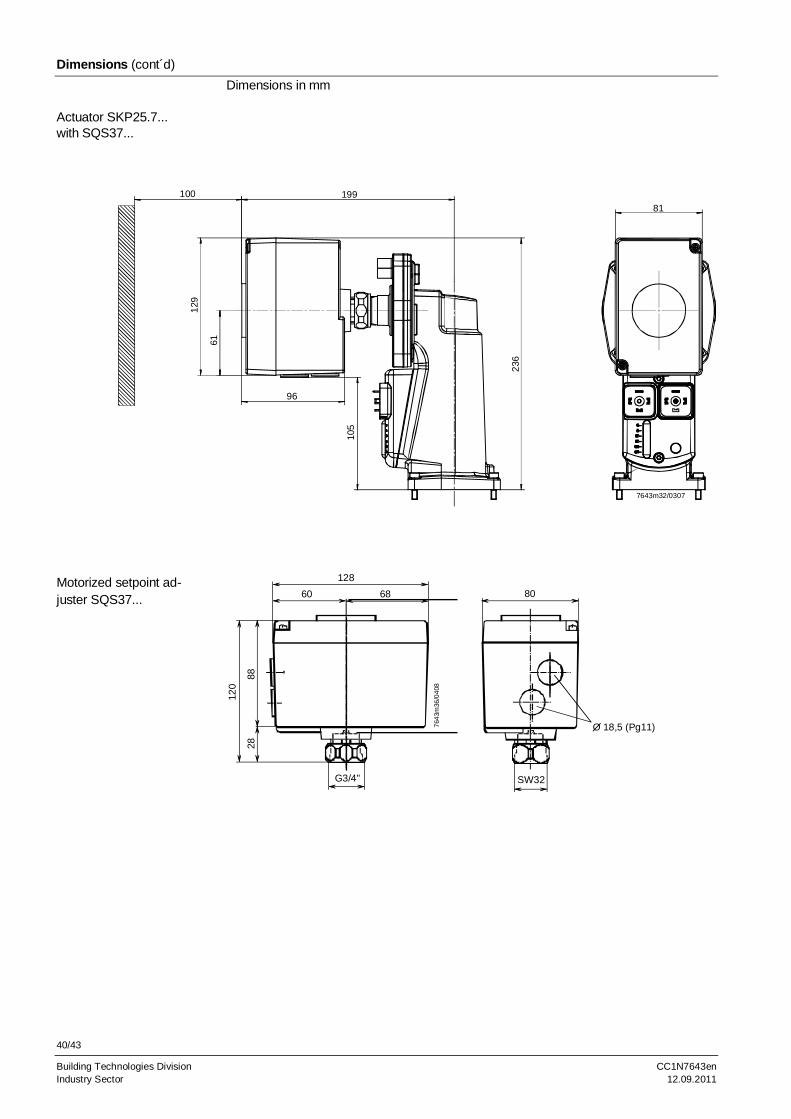
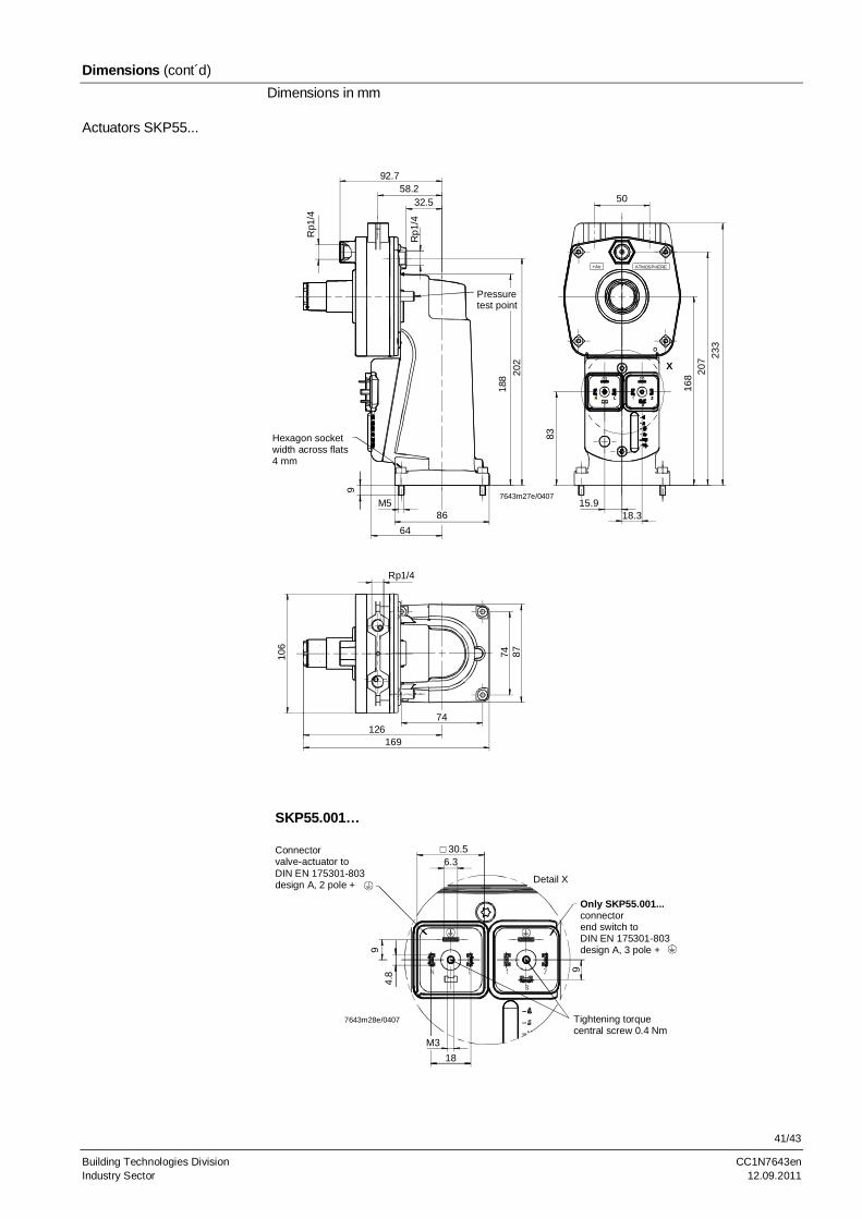
Dimensions (cont´d)
Dimensions in mm
96.2
32.5
Rp1/4
Pressure test point
18
8 20
2 22
1
86
M5
9
Hexagon socketwidth across flats6 mm
64
Rp1/4
X
15.8
18.3
83
168
200
10
6
98
141
74
74 87
7643m19e/0407
SKP25.001… / SKL25.001…
Connectorvalve-actuator to DIN EN 175301-803design A, 2 pole + Only SKP25.001... /
SKL25.001...connectorend switch toDIN EN 175301-803design A, 3 pole +