20
Actuators SQ 05.2 – SQ 14.2/SQR 05.2 – SQR 14.2 SQEx 05.2 – SQEx 14.2/SQREx 05.2 – SQREx 14.2 AUMA NORM (without controls) Functional Safety Manual
| Date post: | 12-Feb-2018 |
| Category: |
Documents |
| Upload: | truongkhuong |
| View: | 216 times |
| Download: | 1 times |
Actuators
SQ 05.2 – SQ 14.2/SQR 05.2 – SQR 14.2
SQEx 05.2 – SQEx 14.2/SQREx 05.2 – SQREx 14.2
AUMA NORM (without controls)
Functional SafetyManual

NOTICE for use!
This document is only valid in combination with the current operation instructions enclosed with the device.
Purpose of the document:
The present documents informs about the actions required for using the device in safety-related systems inaccordance with IEC 61508 or IEC 61511.
Reference documents:● EXIDA Report No. AUMA 13/06-74 R011, V1R0● Operation instructions (Assembly, operation, commissioning) for actuator
Reference documents can be downloaded from the Internet (www.auma.com) or ordered directly from AUMA(refer to <Addresses>).
Table of contents Page
41. Terminology............................................................................................................................41.1. Abbreviations and concepts
62. Application and validity.........................................................................................................62.1. Range of application62.2. Standards62.3. Valid device types
73. Architecture, configuration and applications......................................................................73.1. Architecture (actuator sizing)73.2. Configuration (setting)73.3. Applications (environmental conditions)
84. Safety instrumented system and safety function...............................................................84.1. Safety instrumented system including an actuator84.2. Safety function84.3. Redundant system architecture
105. Installation, commissioning and operation.........................................................................105.1. Installation115.2. Commissioning115.3. Operation115.4. Lifetime115.5. Decommissioning
126. Tests and maintenance..........................................................................................................126.1. Safety equipment: check126.2. Proof test (verification of safe actuator function)126.2.1. Preliminary tests126.2.2. ESD safety operation (safe operation in direction OPEN/CLOSE): check136.2.3. "Reaction monitoring" fault signal: check136.2.4. Torque switches: check136.3. Reaction monitoring/Partial Valve Stroke Test (PVST)136.4. Maintenance
147. Safety parameters..................................................................................................................147.1. Determination of the parameters147.2. Specific parameters for actuators of SQ .2 type range
2
ActuatorsTable of contents SQ.2 AUMA NORM (without controls)

158. SIL Declaration of Conformity (example).............................................................................
17Index........................................................................................................................................
18Addresses...............................................................................................................................
3
Actuators SQ.2 AUMA NORM (without controls) Table of contents

1. Terminology
Information sources ● IEC 61508-4, Functional safety of electrical/electronic/programmable electronicsafety-related systems – Part 4: Definitions and abbreviations
● IEC 61511-1, Functional safety - Safety instrumented systems for the processindustry sector – Part 1: Framework, definitions, system, hardware and softwarerequirements
1.1. Abbreviations and concepts
To evaluate safety functions, the lambda values or the PFD value (Probability ofDangerous Failure on Demand) and the SFF value (Safe Failure Fraction) are themain requirements. Further figures are required to assess the individual components.These figures are explained in the table below.
Table 1: Abbreviations of safety parameters
DescriptionEnglishFigureNumber of safe failuresLambda Safeλ S
Number of dangerous failuresLambda Dangerousλ D
Number of undetected dangerous fail-ures
Lambda Dangerous Undedectedλ DU
Number of detected hazardous failuresLambda Dangerous Dedectedλ DD
Diagnostic Coverage - ratio betweenthe failure rate of dangerous failuresdetected by diagnostic tests and totalrate of dangerous failures of the com-ponent or subsystem. The diagnosticcoverage does not include any failuresdetected during proof tests.
Diagnostic CoverageDC
Mean time between two failures follow-ing one after the other
Mean Time Between FailureMTBF
Fraction of safe failuresSafe Failure FractionSFF
Average probability of dangerous fail-ures on demand of a safety function.
Average Probability of dangerous Fail-ure on Demand
PFDavg
Ability of a functional unit to execute arequired function while faults or devi-ations are present. HFT = n means thatthe function can still be safely executedfor up to n faults occurring at the sametime.
Hardware Failure ToleranceHFT
Interval for proof testTime for proofTproof
SIL Safety Integrity Level
The international standard IEC 61508 defines 4 levels (SIL 1 through SIL 4).
Safety function Function to be implemented by a safety-related system for risk reduction with theobjective to achieve or maintain a safe state for the plant/equipment with respect toa specific hazardous event.
Safety instrumentedfunction (SIF)
Function with defined safety integrity level (SIL) to achieve functional safety.
Safety instrumentedsystem (SIS)
Safety instrumented system for executing a single or several safety instrumentedfunctions. A SIS consists of sensor(s), logic system and actuator(s).
Safety-related system A safety-related system includes all factors (hardware, software, human factors)necessary to implement one or several safety functions. Consequently failures ofsafety function would result in a significant increase in safety risks for people and/orthe environment.
A safety-related system can comprise stand-alone systems dedicated to perform aparticular safety function or can be integrated into a plant.
4
ActuatorsTerminology SQ.2 AUMA NORM (without controls)

Proof test Periodic test performed to detect dangerous hidden failures in a safety-related systemso that, if necessary, a repair can restore the system to an "as new" condition or asclose as practical to this condition.
MTTR (Mean Time ToRestoration)
Mean time to restoration once a failure has occurred. Indicates the expected meantime to achieve restoration of the system. It is therefore an important parameter forsystem availability. The time for detecting the failure, planning tasks as well asoperating resources is also included. It should be reduced to a minimum.
5
Actuators SQ.2 AUMA NORM (without controls) Terminology

2. Application and validity
2.1. Range of application
AUMA actuators with the safety function mentioned in this manual are intended foroperation of industrial valves and are suitable for use in safety instrumented systemsin accordance with IEC 61508 or IEC 61511.
2.2. Standards
The actuators meet the following requirements:
● IEC 61508, Part 2.0: Functional safety of electrical/electronic/programmableelectronic safety-related systems
● Low Voltage Directive (2006/95/EC)● Directive (EMC) (2004/108/EC)● Explosion protection according to ATEX (depending on version)
2.3. Valid device types
The data on functional safety contained in this manual applies to the device typesindicated.
Table 2: Suitable device types of SQ .2 type range
Parameterstable
ControlType of dutyMotorpower supply
AUMAcontrols
Type
3via externalcontrols
S2-15 minS2-30 minS4-25 %S4-50 %
3-phase ACWithoutSQ 05.2 – SQ 14.2SQR 05.2 – SQR 14.2SQEx 05.2 – SQEx 14.2SQREx 05.2 – SQREx 14.2
Devices may not be altered without prior written consent by AUMA. Unauthorisedalterations may have a negative impacts on the devices' capability to execute a safetyfunction.
6
ActuatorsApplication and validity SQ.2 AUMA NORM (without controls)

3. Architecture, configuration and applications
3.1. Architecture (actuator sizing)
For actuator architecture (actuator sizing) the maximum torques, running torquesand operating times are taken into consideration.
Incorrect actuator architecture can lead to device damage within the safety-related system!
Possible consequences can be valve damage, motor overheating, contactor jamming,defective thyristors, heating up or damage to cables.
→ The actuator technical data must imperatively be observed when selecting theactuator.
→ Sufficient reserves have to be provided to ensure that actuators are capable ofreliably opening or closing the valve even in the event of an accident or under-voltage.
Incorrect actuator sizing may cause a dangerous failure of the safety function ondemand.
3.2. Configuration (setting)
Configuration (setting) of safety-relevant functions are performed as described inthe operation instructions or in the present manual (functional safety).
3.3. Applications (environmental conditions)
When specifying and using the actuators within safety instrumented systems,particular attention has to be paid that the permissible service conditions and theEMC requirements by the peripheral devices are met. Service conditions are indicatedin the technical data sheets:
● Enclosure protection● Corrosion protection● Ambient temperature● Vibration resistanceIf the actual ambient temperatures exceed an average of +40 °C, the lambda valueshave to be incremented by a safety factor. For an average temperature of +60 °C,this factor is defined at 2.5.
7
Actuators SQ.2 AUMA NORM (without controls) Architecture, configuration and applications
4. Safety instrumented system and safety function
4.1. Safety instrumented system including an actuator
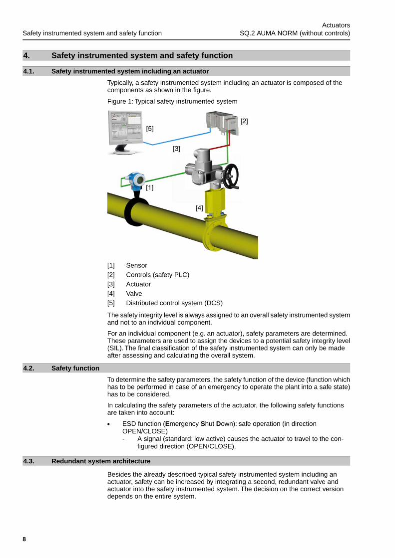
Typically, a safety instrumented system including an actuator is composed of thecomponents as shown in the figure.
Figure 1: Typical safety instrumented system
[1] Sensor[2] Controls (safety PLC)[3] Actuator[4] Valve[5] Distributed control system (DCS)
The safety integrity level is always assigned to an overall safety instrumented systemand not to an individual component.
For an individual component (e.g. an actuator), safety parameters are determined.These parameters are used to assign the devices to a potential safety integrity level(SIL). The final classification of the safety instrumented system can only be madeafter assessing and calculating the overall system.
4.2. Safety function
To determine the safety parameters, the safety function of the device (function whichhas to be performed in case of an emergency to operate the plant into a safe state)has to be considered.
In calculating the safety parameters of the actuator, the following safety functionsare taken into account:
● ESD function (Emergency Shut Down): safe operation (in directionOPEN/CLOSE)- A signal (standard: low active) causes the actuator to travel to the con-
figured direction (OPEN/CLOSE).
4.3. Redundant system architecture
Besides the already described typical safety instrumented system including anactuator, safety can be increased by integrating a second, redundant valve andactuator into the safety instrumented system. The decision on the correct versiondepends on the entire system.
8
ActuatorsSafety instrumented system and safety function SQ.2 AUMA NORM (without controls)

Figure 2: Redundant system with ESD for safe operation in direction CLOSE
Figure 3: Redundant system with ESD for safe operation in direction OPEN
9
Actuators SQ.2 AUMA NORM (without controls) Safety instrumented system and safety function
5. Installation, commissioning and operation
Information Installation and commissioning have to be documented by means of an assemblyreport and an inspection certificate. Installation must be carried out exclusively bysuitably qualified personnel.
5.1. Installation
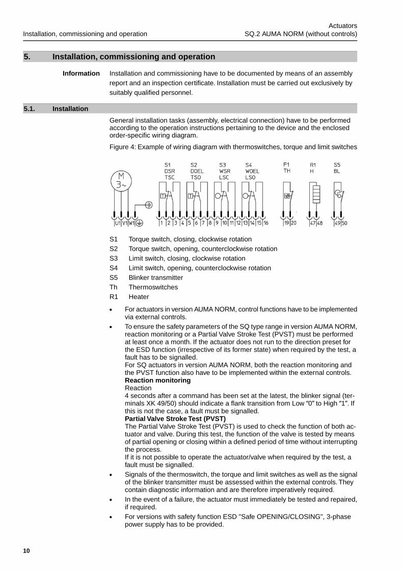
General installation tasks (assembly, electrical connection) have to be performedaccording to the operation instructions pertaining to the device and the enclosedorder-specific wiring diagram.
Figure 4: Example of wiring diagram with thermoswitches, torque and limit switches
S1 Torque switch, closing, clockwise rotationS2 Torque switch, opening, counterclockwise rotationS3 Limit switch, closing, clockwise rotationS4 Limit switch, opening, counterclockwise rotationS5 Blinker transmitterTh ThermoswitchesR1 Heater
● For actuators in version AUMA NORM, control functions have to be implementedvia external controls.
● To ensure the safety parameters of the SQ type range in version AUMA NORM,reaction monitoring or a Partial Valve Stroke Test (PVST) must be performedat least once a month. If the actuator does not run to the direction preset forthe ESD function (irrespective of its former state) when required by the test, afault has to be signalled.For SQ actuators in version AUMA NORM, both the reaction monitoring andthe PVST function also have to be implemented within the external controls.Reaction monitoringReaction4 seconds after a command has been set at the latest, the blinker signal (ter-minals XK 49/50) should indicate a flank transition from Low “0” to High “1”. Ifthis is not the case, a fault must be signalled.Partial Valve Stroke Test (PVST)The Partial Valve Stroke Test (PVST) is used to check the function of both ac-tuator and valve. During this test, the function of the valve is tested by meansof partial opening or closing within a defined period of time without interruptingthe process.If it is not possible to operate the actuator/valve when required by the test, afault must be signalled.
● Signals of the thermoswitch, the torque and limit switches as well as the signalof the blinker transmitter must be assessed within the external controls. Theycontain diagnostic information and are therefore imperatively required.
● In the event of a failure, the actuator must immediately be tested and repaired,if required.
● For versions with safety function ESD "Safe OPENING/CLOSING", 3-phasepower supply has to be provided.
10
ActuatorsInstallation, commissioning and operation SQ.2 AUMA NORM (without controls)
5.2. Commissioning
The operation instructions pertaining to the device must be observed for generalcommissioning.
After commissioning, the safe actuator function must be verified. The verificationmust at least comprise all tests described in the <Safety equipment: check> and<Proof test (verification of safe actuator function)> chapters.
5.3. Operation
Regular maintenance and device checks in the Tproof intervals as defined by theplant operator are the basis for safe operation.
The operation instructions pertaining to the device must be observed for operation.
The plant operator is responsible for power supply.
5.4. Lifetime
Actuator lifetime is described in the technical data sheets or the operation instructions.
Safety-related parameters are valid for the cycles or modulating steps specified inthe technical data for typical periods of up to 10 years. After this period, the probabilityof failure increases.
5.5. Decommissioning
When decommissioning an actuator with safety functions, the following must beobserved:
● Impact of decommissioning on relevant devices, equipment or other work mustbe evaluated.
● Safety and warning instructions contained in the actuator operation instructionsmust be met.
● Decommissioning must be carried out exclusively by suitably qualified personnel.● Decommissioning must be recorded in compliance with regular requirements.
11
Actuators SQ.2 AUMA NORM (without controls) Installation, commissioning and operation

6. Tests and maintenanceTest and maintenance tasks may only be performed by authorised personnel whohave been trained on functional safety.
Information Any test/maintenance must be recorded in a test/maintenance report.
6.1. Safety equipment: check
All safety functions within a safety equipment must be checked for perfect functionalityand safety at appropriate intervals. The intervals for safety equipment checks are tobe defined by the plant operator.
6.2. Proof test (verification of safe actuator function)
The proof test serves the purpose to verify the safety-related functions of the actuator.
Proof tests shall reveal dangerous faults which might remain undetected until a safetyfunction is started and consequently result in a potential danger.
For test of the safety function, this function is requested by external controls. As aconsequence, the actuator must perform the safety function without fault.
Information The power supply of the actuator must also be considered during the proof test.
Intervals:
A proof test interval describes the time between two proof tests. Functionality mustbe checked in appropriate intervals. The intervals are to be defined by the plantoperator.
In any case, the safety-related functions must be checked after commissioning andfollowing any maintenance work or repair as well as during the Tproof intervals definedin safety assessment.
6.2.1. Preliminary tests
The actuator system has to be subjected to a visual inspection first. The systemshould be checked for outside damage and corrosion. Furthermore, the electricaland mechanical connections should be checked and the actuator be monitored forconspicuous noise. By means of run time measurement of the opening and closingprocedures, further faults can be detected in case of deviation.
6.2.2. ESD safety operation (safe operation in direction OPEN/CLOSE): check
Configuration The test is valid for the version with ESD function.
During the ESD function test, full valve stroke or full travel of the valve should beperformed.
Test procedure When switching the external controls accordingly, safety operation into the desireddirection must be triggered.
Test sequence 1. Operate actuator in mid-position or at sufficient distance from end positions.2. Execute operation command (default operation) in opposite direction of the
configured ESD safety function:→ For "safe operation in direction CLOSE" (ESD in direction CLOSE):
Start default operation command in direction OPEN.→ For "safe operation in direction OPEN" (ESD in direction OPEN): Start
default operation command in direction CLOSE.
3. Start safety operation during default operation:
➥ Safety function is correct if the actuator stops and performs a safety operationinto the desired direction.
➥ No fault signal may be issued.
12
ActuatorsTests and maintenance SQ.2 AUMA NORM (without controls)

6.2.3. "Reaction monitoring" fault signal: check
Configuration The test is valid for the version with ESD function.
Test procedure If the motor does not rotate within a defined time once a safety operation wastriggered, a fault must be signalled.
Test sequence 1. Operate actuator in mid-position or at sufficient distance from end positions.2. Lock motor operation to ensure manual drive remains engaged.3. Start ESD safety operation:
➥ The fault signal is correct if a fault is signalled within 4 seconds.
4. Once the test is complete, deactivate motor lock.
6.2.4. Torque switches: check
Torque switches are checked using the test buttons. Refer to relevant chapters inthe actuator operation instructions.
6.3. Reaction monitoring/Partial Valve Stroke Test (PVST)
Safety parameters indicated for SQ.2 actuators in AUMA NORM version are onlyvalid in combination with monthly reaction monitoring or with monthly Partial ValveStroke Tests (PVST).
As described in the <Installation> chapter, the functions have to be implemented inthe external controls.
6.4. Maintenance
Maintenance and service tasks may only be performed by authorised personnel whohave been trained on functional safety (refer to chapter 5).
Once maintenance and service tasks have been finished, the functional test mustbe completed by a validating process of the safety function including at least thetests described in the <Safety equipment: check> and <Proof test (verification ofsafe actuator function)> chapters.
13
Actuators SQ.2 AUMA NORM (without controls) Tests and maintenance

7. Safety parameters
7.1. Determination of the parameters
● The calculation of the safety instrumented parameters is based on the indicatedsafety functions. Hardware assessments are based on Failure Modes, Effectsand Diagnostic Analysis (FMEDA). FMEDA is a step to assess functional devicesafety in compliance with IEC 61508. On the basis of FMEDA, the failure ratesand the fraction of safe failures of a device are determined.
● Experience data and data taken from the EXIDA database for mechanicalcomponents is used to deduce failure rates.The electronic failure rates as basefailure rates are taken from the SIEMENS Standard SN 29500.
● In compliance with table 2 of IEC 61508-1, the average target PFD values forsystems with low demand mode are:- SIL 1 safety functions: ≥ 10-2 to < 10-1
- SIL 2 safety functions: ≥ 10-3 to < 10-2
- SIL 3 safety functions: ≥ 10-4 to < 10-3
Since actuators only represent a part of the overall safety function, the actuatorPFD should not account for more than 25 % of the permissible total value(PFDavg) of a safety function. This results in the following values:- Actuator PFD for SIL 2 applications: ≤ 2.50E-03
● The electric actuators are classified as type A components with a hardwarefault tolerance of 0.The SFF for the type A subsystem should be <60 % accord-ing to table 2 of IEC 61508-2 for SIL 1 (subsystems with a hardware fault toler-ance of 0). The SFF for the type A subsystem should be between 60 % and<90 % according to table 2 of IEC 61508-2 for SIL 2 (subsystems with a hard-ware fault tolerance of 0).
802 hours were assumed for the MTTR. Out of these, 730 hours are used for thediagnostic test interval (e.g. PVST) and 72 hours for the MRT.
As previously mentioned in the architecture section, safeguarding power supply andresulting calculations are the responsibility of the plant operator.
The plant operator is responsible for complying with assumed MTTR. Otherwise thedata of the quantitative results is no longer valid.
7.2. Specific parameters for actuators of SQ .2 type range
The following parameter table provides the safety parameters for the differentversions. Data records of safety instrumented parameters of all variants are availablewithin the EXIDA test report.
Table 3: SQ.2 type range in AUMA NORM version (without actuator controls)
SQ 05.2 – SQ 14.2/SQR 05.2 – SQR 14.2SQEx 05.2 – SQEx 14.2/SQREx 05.2 – SQREx 14.2
ESDSafety functionAUMA 13/06-74 R11Version V1R0
Reference
0 FITλsafe
259 FITλ DD
73 FITλ DU
77 %DCD
179 yearsMTBF
77 %SFF
PFDavg = 8.24E-04T[proof] = 1 year
14
ActuatorsSafety parameters SQ.2 AUMA NORM (without controls)

8. SIL Declaration of Conformity (example)
15
Actuators SQ.2 AUMA NORM (without controls) SIL Declaration of Conformity (example)

16
ActuatorsSIL Declaration of Conformity (example) SQ.2 AUMA NORM (without controls)
Index
AActuator definition 7Ambient conditions 7Architecture 7
CCommissioning 11Configuration 7
DDC 4Declaration of Conformity 15Decommissioning 11Device types 6Diagnostic coverage (DC) 4
HHFT 4
IInstallation 10Interval for proof test 4
LLambda values 4 , 14Lifetime 11Low Demand Mode 14
MMTBF 4MTTR (Mean Time To Restor-ation)
5
Maintenance 13Mean Time Between Failures(MTBF)
4
OOperation 11
PPFD 4PFD for actuator 14Parameters, safety 14Partial Valve Stroke Test(PVST)
13
Probability of failure 4 , 11Proof test 5 , 12 , 12
RRange of application 6Reaction monitoring 13
SSFF 4SIL 4Safe failure fraction (SFF) 4 , 14Safety function 4 , 8Safety instrumented function(SIF)
4
Safety instrumented system 8Safety instrumented system(SIS)
4
Safety-related system 4Service conditions 7Setting 7Standards 6
TT proof 4Tests 12
17
Actuators SQ.2 AUMA NORM (without controls) Index

Europe
AUMA Riester GmbH & Co. KG
Plant MüllheimDE 79373 MüllheimTel +49 7631 809 - [email protected]
Plant Ostfildern-NellingenDE 73747 OstfildernTel +49 711 34803 - [email protected]
Service-Center BayernDE 85386 EchingTel +49 81 65 9017- [email protected]
Service-Center KölnDE 50858 KölnTel +49 2234 2037 - [email protected]
Service-Center MagdeburgDE 39167 NiederndodelebenTel +49 39204 759 - [email protected]
AUMA-Armaturenantriebe Ges.m.b.H.AT 2512 TribuswinkelTel +43 2252 [email protected]
AUMA BENELUX B.V. B. A.BE 8800 RoeselareTel +32 51 24 24 [email protected]
ProStream Group Ltd.BG 1632 SofiaTel +359 2 [email protected]
OOO “Dunkan-Privod”BY 220004 MinskTel +375 29 [email protected]
AUMA (Schweiz) AGCH 8965 BerikonTel +41 566 [email protected]
AUMA Servopohony spol. s.r.o.CZ 250 01 Brandýs n.L.-St.BoleslavTel +420 326 396 [email protected]
GRØNBECH & SØNNER A/SDK 2450 København SVTel +45 33 26 63 [email protected]
IBEROPLAN S.A.ES 28027 MadridTel +34 91 [email protected]
AUMA Finland OyFI 02230 EspooTel +358 9 5840 [email protected]
AUMA France S.A.R.L.FR 95157 Taverny CedexTel +33 1 [email protected]
AUMA ACTUATORS Ltd.GB Clevedon, North Somerset BS21 6THTel +44 1275 [email protected]
D. G. Bellos & Co. O.E.GR 13673 Acharnai, AthensTel +30 210 [email protected]
APIS CENTAR d. o. o.HR 10437 BestovjeTel +385 1 6531 [email protected]
Fabo Kereskedelmi és Szolgáltató Kft.HU 8800 NagykanizsaTel +36 93/[email protected]
Falkinn HFIS 108 ReykjavikTel +00354 540 [email protected]
AUMA ITALIANA S.r.l. a socio unicoIT 20023 Cerro Maggiore (MI)Tel +39 0331 [email protected]
AUMA BENELUX B.V.LU Leiden (NL)Tel +31 71 581 40 [email protected]
NB Engineering ServicesMT ZBR 08 ZabbarTel + 356 2169 [email protected]
AUMA BENELUX B.V.NL 2314 XT LeidenTel +31 71 581 40 [email protected]
SIGUM A. S.NO 1338 SandvikaTel +47 [email protected]
AUMA Polska Sp. z o.o.PL 41-219 SosnowiecTel +48 32 783 52 [email protected]
INDUSTRAPT 2710-297 SintraTel +351 2 1910 95 [email protected]
SAUTECHRO 011783 BucurestiTel +40 372 [email protected]
OOO PRIWODY AUMARU 141402 Khimki, Moscow regionTel +7 495 221 64 [email protected]
OOO PRIWODY AUMARU 125362 MoscowTel +7 495 787 78 [email protected]
ERICHS ARMATUR ABSE 20039 MalmöTel +46 40 [email protected]
ELSO-b, s.r.o.SK 94901 NitraTel +421 905/[email protected]
Auma Endüstri Kontrol Sistemleri LimitedSirketiTR 06810 AnkaraTel +90 312 217 32 [email protected]
AUMA Technology Automations LtdUA 02099 KievTel +38 044 [email protected]
Africa
Solution Technique Contrôle CommandeDZ Bir Mourad Rais, AlgiersTel +213 21 56 42 09/[email protected]
A.T.E.C.EG CairoTel +20 2 23599680 - [email protected]
SAMIREGMA 203000 CasablancaTel +212 5 22 40 09 [email protected]
MANZ INCORPORATED LTD.NG Port HarcourtTel [email protected]
18
AUMA worldwide

AUMA South Africa (Pty) Ltd.ZA 1560 SpringsTel +27 11 [email protected]
America
AUMA Argentina Rep.OfficeAR Buenos AiresTel +54 11 4737 [email protected]
AUMA Automação do Brazil ltda.BR Sao PauloTel +55 11 [email protected]
TROY-ONTOR Inc.CA L4N 8X1 Barrie, OntarioTel +1 705 [email protected]
AUMA Chile Representative OfficeCL 9500414 BuinTel +56 2 821 [email protected]
Ferrostaal de Colombia Ltda.CO Bogotá D.C.Tel +57 1 401 [email protected]
Transcontinental Trading Overseas SA.CU Ciudad HabanaTel +53 7 208 9603 / 208 [email protected]
AUMA Región Andina & CentroaméricaEC QuitoTel +593 2 245 [email protected]
Corsusa International S.A.C.PE Miraflores - LimaTel +511444-1200 / 0044 / [email protected]
Control Technologies LimitedTT Marabella,Trinidad, W.I.Tel + 1 868 658 1744/5011www.ctltech.com
AUMA ACTUATORS INC.US PA 15317 CanonsburgTel +1 724-743-AUMA (2862)[email protected]
SuplibarcaVE Maracaibo, Estado, ZuliaTel +58 261 7 555 [email protected]
Asia
AUMA Actuators UAE Support OfficeAE 287 Abu DhabiTel +971 [email protected]
AUMA Actuators Middle EastBH 152 68 SalmabadTel +97 3 [email protected]
Mikuni (B) Sdn. Bhd.BN KA1189 Kuala BelaitTel + 673 3331269 / [email protected]
AUMA Actuators (Tianjin) Co., Ltd. BeijingBranchCN 100020 BeijingTel +86 10 8225 [email protected]
PERFECT CONTROLS Ltd.HK Tsuen Wan, KowloonTel +852 2493 [email protected]
PT. Carakamas Inti AlamID 11460 JakartaTel +62 [email protected]
AUMA INDIA PRIVATE LIMITED.IN 560 058 BangaloreTel +91 80 2839 [email protected]
ITG - Iranians Torque GeneratorIR 13998-34411 [email protected]
Trans-Jordan Electro Mechanical SuppliesJO 11133 AmmanTel +962 - 6 - [email protected]
AUMA JAPAN Co., Ltd.JP 211-0016 Kawasaki-shi, KanagawaTel +81-(0)[email protected]
DW Controls Co., Ltd.KR 153-702 Gasan-dong, GeumChun-Gu,,SeoulTel +82 2 2624 [email protected]
Al-Arfaj Engineering Co WLLKW 22004 SalmiyahTel [email protected]
TOO “Armaturny Center”KZ 060005 AtyrauTel +7 7122 454 [email protected]
Network EngineeringLB 4501 7401 JBEIL, BeirutTel +961 9 [email protected]
AUMA Malaysia OfficeMY 70300 Seremban, Negeri SembilanTel +606 633 [email protected]
Mustafa Sultan Science & Industry Co LLCOM RuwiTel +968 24 [email protected]
FLOWTORK TECHNOLOGIESCORPORATIONPH 1550 Mandaluyong CityTel +63 2 532 [email protected]
M & C Group of CompaniesPK 54000 Cavalry Ground, Lahore CanttTel +92 42 3665 0542, +92 42 3668 [email protected]
Petrogulf W.L.LQA DohaTel +974 [email protected]
AUMA Saudi Arabia Support OfficeSA 31952 Al KhobarTel + 966 5 5359 [email protected]
AUMA ACTUATORS (Singapore) Pte Ltd.SG 569551 SingaporeTel +65 6 [email protected]
NETWORK ENGINEERINGSY Homs+963 31 231 [email protected]
Sunny Valves and Intertrade Corp. Ltd.TH 10120 Yannawa, BangkokTel +66 2 [email protected]
Top Advance Enterprises Ltd.TW Jhonghe City,Taipei Hsien (235)Tel +886 2 2225 [email protected]
AUMA Vietnam Hanoi ROVN Hanoi+84 4 [email protected]
Australia
BARRON GJM Pty. Ltd.AU NSW 1570 ArtarmonTel +61 2 8437 [email protected]
19
AUMA worldwide

AUMA Riester GmbH & Co. KG
P.O.Box 1362DE 79373 MuellheimTel +49 7631 809 - 0Fax +49 7631 809 - [email protected]
Y006.345/003/en/1.14
For detailed information on AUMA products refer to the Internet: www.auma.com


