31
UNCLASSIFIED AD 2 8 6 200 ARMED SERVICES TECHNICAL INFORMATION AGENCY ARLINGTON HALL STATION ARLINGTON 12, VIRGINIA w UNCLASSIFIED
| Date post: | 18-Apr-2018 |
| Category: |
Documents |
| Upload: | hoangtuyen |
| View: | 218 times |
| Download: | 5 times |

UNCLASSIFIED
AD 2 8 6 200
ARMED SERVICES TECHNICAL INFORMATION AGENCYARLINGTON HALL STATIONARLINGTON 12, VIRGINIAw
UNCLASSIFIED

NOTICE: When government or other drawings, speci-fications or other data are used for any purposeother than in connection with a definitely relatedgovernment procurement operation, the U. S.Government thereby incurs no responsibility, nor anyobligation whatsoever; and the fact that the Govern-ment may have fonmilated, furnished, or in any waysupplied the said drawings, specifications, or otherdata is not to be regarded by implication or other-wise as in any manner licensing the holder or anyother person or corporation, or conveying any rightsor permission to manufacture, use or sell anypatented invention that may in any way be relatedthereto.
it

FTD-TT- 6?'-738
"TRANSLATION
ELIMINATINO AIRCRAFT ENOGIN VTDRATION
BY
Me Yee Levtt and Yu. A. Rolosov
FOREIGN TECHNOLOGY
DIVISION
AIR FORCE SYSTEMS COMMAND
WRIGHT-PATTERSON AIR FORCE BASE
S4 ] •OHIO
4
! -.

REPRODUCTION QUALITY NOTICE
This document is the best quality available. The copy furnishedto DTIC contained pages that may have the following qualityproblems:
* Pages smaller or larger than normal.
* Pages with background color or light colored printing.
* Pages with small type or poor printing; and or
* Pages with continuous tone material or colorphotographs.
Due to various output media available these conditions may ormay not cause poor legibility in the microfiche or hardcopy outputyou receive.
E lf this block is checked, the copy furnished to DTICcontained pages with color printing, that when reproduced inBlack and White, may change detail of the original copy.

UNIDIflRb ROUGH DRAFTTRAWSATION
ELIMINATING AIRCRAFT ENGINE VIBRATION
B3y- M. Ye. Le,-vit and Yu. A. Kolosov
Engai~ih Pages: 241
Source: Tekhnologicheskiye Metody PovysheniyaXachestva Detalcy J. Uzlov Aviadvigateley,Oboron~giz, 1961., PP 13O-I147
Qcl-i303
HM '4,(..4: 10w o"U7 ANtY AN ALYVTICAL 0ý* ~~~ 't'170kAL CUMWOýW7 *AATEMP.HT$ VR THEORIE'" W'A~h~'
ADVOCATED M4~ IMP LIE15 ARE TtIOSE Of THE SOURCEMiJD 1)(i tAOY HUCESSARILY REFLECT THE POSITION Th/MSI. PI710F! skvcý, IA!3Op~ OPINOION Fir THE~ ('fEIl3 TECWHOLOGY pj.ý pOflE;44, ycUWfioi.tV CvIVIMMs vi VPAg'L, cld310.
f -f-62--T58/1+2+-4 iJ 26 June

ELIMINATING AIRCRAFT ENGINE VIBRATION
M. Ye. Levit, Candidate of Technical Sciences,
and Yu. A. Kolosov, Engineer
With the development of the new technology, a great deal of
attention is being directed to the study of elastic oscillations -
their calculation and prevention. The works of many researchers and
plant engineers are devoted to this problem.
In spite of the decided achievements in this area, the study of
the causes of machine vibration remains a complicated problem, because
it is difficult to take into account and evaluate the influence of
many and varied factors. Among these are various types of deformation,
asymmetric rigidity, yielding of supports, etc. However, one effect
is certain and basic; it is imbalance in high-rpm assemblies, whai•'3
leads the system to vibrate with an amplitude which is a function of
the degree of imbalance.
The vibrations transmitted to the machine can cause resonaeivt In
its bracing units, disrupt the normal operation of fittings and ntwo,-
ments, and considerably lower its operating resources. The osciisnz
have a substantial effect on the maintenance persorrne3. Fov e :ui;ptl'
¶ oscillations above 50 cps can be propagated through w.e human body
FTD-TT-62-738/i+2+4'

without any noticeable fading. This heightens thfi:, ý)etata e effe•,
on the central nervous system and on the organism as a whole. Under
the action of vibrations, serious disorders result in the human
organism.
Inasmuch as machine vibrations are first 6f all a function of
rotor imbalance, the development of methods for higher-precision
balancing and the creation of the necessary arrangements to guarantee
vibrationless operation take on great importance.
Vibration in gas-turbine engines and ways of reducing it
The systematic improvement of the design of gas-turbine engines
introduced many methods of combatting vibrations and, owing to the
design features of the engines (one piece and multipiece rotors),
oscillations are observed which have varied character and form,
however, the methods of eliminating them are basically general. Thev.
come down to determining the magnitude of the vibrati on overload of
the engine and rebalancing of the rotors. Test btands are used, and
each experiment includes complete dismantling of the engine. This
method, although it corresponds to actual operating conditions and takes
into account dynamic rotor deflections, temperature and axial force,
it has the essential disadvantage of requiring overhaolinng of the
engine, which leads to a change in the initial conditlons (the p.A
cision of parts, clearances in joints, bearing seatings, etci.).
At the present time, the method of reducing the arnplit'Jd> of
vibrations which exceed the limits of engineering conditions :
chiefly the following:
i. Damping of the oscillations of the system ajid tuning them oili.
FTD-TT-62-73 8 /i+2+- -2-

of the resonance conditions of operation.
2. Increasing the quality and accuracy o'f eyiamiic eq•uil brium,
allowing the vibrations of the system to be decreased.
Without touching on the first o'f these, let us say that so far
the basis of the method of dynamic balancing of' rotating bodies :1i
the assumption of their absolute rigidity. Therefore, any number of
unbalanced centrifugal forces is reduced to two forces, lying usually
at the outer planes. Because of this, the balancing machines are
fitted with two supports, on which the body to be balanced turns at
low rpm (400 to 800 rpm). By choosing the magnitude and location for
the balancing weight, the action of the unbalanced centrifugal force
is eliminated for one support. The same operatlon is carried out
for the other support. However, the use of hIgh rpm machines shows
that even comparatively rigid rotors are deformed during transition
to higher speeds. Deflections increase sharply and the rotor takes
on the so-called elastic Imbalance. This imbalance leads to a stron;
increase in the amplitude of oscillations. Therefore, a imilethod for
balancing high rpm elastic systems having great masts .1b a real
problem.
If rotors with great deformation belong to the category of clastl,,
systems, then they must be balanced at operat.n1-' '-1,• v IIoeven;, (..!,j!
kind of balancing is very difficult under the presen; condition,",
requires high power (25,000 to 50,000 kw), compliated apparatus and
a comparatively long time for balancing.
In this connection the authors, with the participation of
engineers I. I. Bayenko and G. K. Devyatov, have, ,,Cudied a weJ, '.1,,d
of balancing full-scale rotors at working rpm •.•ih i small cýxpe,..
ture of power for their running. This method dafffei.- fr•m the exist2,1;1
?TD-TT-62-73 8 /1+2+ 4 --

ones in that the correcting weights are introduced nut only at the
outer planes, but also at one or more of the dxiv-ing planes along the
length of the rotor. With this, rotor deformation (deflectioii of
elastic line) is reduced. The location and magnitude of imbalance ic
determined by special pick-ups at'the operating spebed of the roto.•
Although it is impossible to eliminate vIbratloi- completely in
turbo-jet engines, the proposed method ensures 1tLt 4t will be lowered
to an acceptable level.
The method of balancing and the equgpeint. used
The balancing of full-scale engines and their assemblies by the
proposed method is carried out on a special stand, wn:ch allows bal-
ancing to be done at operating rpm. The rotor is set up together
with the housing, i.e., on its own supports.
The schematic diagram of the stand (Fig. I) provides for the
location of the object of study in the chamber. Jiere the suspensloi
conditions for the object are close to the actua.L ones, in order to
preserve its frequency characteristic Jnso,'ar au poEs.lble.
The rotor is started up by a d-c electric (itor through a gewoa
box. In order to exclude the effect of drivinýg; on tu1e oscdllal Ilons
of the object, there is a free-running clutch in thJie rvystem.
The chamber in which the object of study Js ir:,•tolled crn bu oji
varied design. A vacuum can be created in it, (J to 3 mm u;), whic."I
allows the power required to turn the huge rotor to be much :!r..::.'
For a number of objects, a separate vacuum chambex, iuued not b ,-
but having provided the necessary seals, a vavluu Jb ca.oterl
engine housing. For example, when examinilhiS vibra1Jti, It i.:':,e VY.-.
engine on an MAI-1 stand, the compressor housia,'., fitted with three

-P 041 I
9, C) 0r A~4F !: cr-I 'o v v~
, C) £Zd '-P *'
'd. 0, r'I 0 Cý -1O LnCl, 4.)0
6n -3CH > a) c\I. --- o EC ~ \J-:'C)O -:- (D.
A__WQ) Q) F\ .- l ) -'-I.. 4ý3
--- ) DD .9-4 0 .J1) 0) v K,\ it)I
Cdi 4- td).)) § .,f; -- 4- d m " (D d 5
0o 0 Q~C . ) 0 - t'\ to
A H E > - 1.5 P- 00 -W\Mý44
P- n-I 0 rl ;q'C~ "H
404
(1) a H ) 'c; C) F HH t C)
xi IV 00 (o C
Do *Ci) -- ~~ H0'l)b i -
IW -H 01 FA 4 ' 4-)
;) O Ir ~ 4 'r. F - 4 .r C) U F)Cl 4.) 3)(
o W) Hi 0 L )
0 ) bD C\J 1.,0 ) 0)C Io 01 bf' i 0 P4~ fr 1 0)
C) a -i a, 0 W'* .
Hý W. -H ;-o 1)- v ý V~ r" dt \
co .4o F- )Eýorýw

sealing disco, a cup-type seal along the comp oc-oi• .L-,aft ai.udpl',
served successfully as a vacuum chamber (Fig. 2). But Someticieb the
housing coannut be sealed reliably enough. IL 1-b beitter to use
special vacuum chamber then.
7 2 3
Fig. 2. Diagram of vacuum apparatus with aVK-i engine. I) electric motor; 2) gesi';3) free-running clutch; 4) engine to bestudied; 5) sealing ring; 6) frame; 7.) lub-rication system; 8) vacuum system.
An MAI-3 stand was built in order to study the vibrations of t1v:
axial compressors, where the vacuum chamber was of sclf-containe-,.
design.
It is a steel cylinder closed at the endt by (jCzc;s (Fig. 3).
There is a cup seal in the forward disc wh:1c .i it airtighlt .:>nr
the drive shaft. In addition, there As a hatch :In the disc for coy-
venience In mounting the balancing weights. The disc ib' bolted to
the flange of the chamber. This connection :is mnadu .•ri jght. vi7.ý4
vacuum-rubber gasket 2 to 3 mm in diameter,
A special nacelle is mounted on the rear disc, tlriigh ,hl.h ,,]
electrical contacts and oil lines exit, and to whiA.!B the p(., K:'r.
the vacuum pumps are connected. In this same rdim;i there .Ls a., ;w-
opening for the main drain of the oil systemv,
Along the outer surface of the chamber a.re -evci..'al strong
-5-

stringers connected by corner plateu, The t3 -.&:.• o on~oree,
four adjustable journals are mounted on theni, by•• c1h.h the chakdber
is secured to the framne, which iB mounted on the 1ý)na.&-,, 1e, in
addition to this, there is in the chamber a hatch for ease in getting
to the rotor and several tens of openings for mounting the capacitIve
pickups. Two annular frames are welded inside. th,- iI.amber for
mounting the object to be studied.
00/
pi ecrnprý
Fig. 3. Over-.alJ view of vacuum •iambt,'with axial compressor.1 ILJLi W I - _
2R-
T1TTHTMTFFtTI7ý1iFig. 4. Calculated stress d1agraiH o.'t.vacuum chamber.
-6-

The chamber of the stand, in the calculat-li, uf` both Y:t-idlty
and stability, is considered an a::ially symnmetri.c shell aubjected to
the simultaneous action of axial com.rcoi6son anti uniform tralsverse
pressure (Fig. 4). Under the action of these folocet, the shell, can
retain its cylindrical shape only up to ]oowrI ,p'bctical) load values.
At critical loads this equilibriuin •hpe becomes ,unitable and the
shell can bulge.
Let us assume that tbe shel.2 is thin and its edges, are free of
support. For this case S. P. Timoshenko [i] puto fmith a simplified
formula for determining the critical load
qcr J= W
where E = 2.1 108 kg/cm2 is Young's modulus for the material of the
chamber; 6 the thickness of the shell in cm; R the radius od the shell
(60 cm); I the length of the shell in cm; [j, Poisson's ratio; _ atmos.,
pheric pressure in kg/cm2 ; and h the number of parts about the pe•'.k,
ery at which the shell bulges. It is determined as a function of
the ratios 6/2R and 1/2R according to the :i'iý,ýlg. 251 of
Timoshenko's work [i].
In our case a high vacuum is created io:.Adc the ohamber with
atmospheric pressure on the outside. Thexitform, the miaximum piaessur&
drop _ will equal I kg/cm2.
In order to increase the stability reserv-. .]oin.itudinal proftile
ribs (stringers) and transverse ribs (frames) are '.eci i., t . '.
When calculating stability, the presence, thVe ve-Lorceme'-,t
should be taken into account. However, cal.cu.ta•iion of tho
of a reinforced shell is very complicatcd :mli•( ,
limit ourselves to the calculation of stability of an •nlryeinforced
"-7-

shell, taking into accour.t atv n•-th an&d t•c:-?i:•
Calculations have been made V'c¢' vari•touO vl es of 6 and Z. The
results of the calculat].'inn that 1,h i'50 ;:'ý and 6 1 1 cm
even an unreinforced shell hati a stablilty resele
S.... .. 29j ..q
The introduction of rel' forcing ribs incxreost_- the stabillty
reserve even more.
The drive system ib self-contained owing, to which it is possible
to turn various rotos wItnout modifying It,
Turning of the object te be examined JB accomplished by a
130-kw d-c electric niotov cpe:rat~itg at 1000 rp-m. Smoothness of
turning is attained by the starting and sh.i.t rlheostats. The shaft,
of the electric motor is connected to the gear, box by a slit spring;
the gear box is mounted on a special stand on a, s.9ogle base plaTe
with the electric motor.
The drive shaft of the gear box is connected to the ohfat of the
free-running clutch, which in this case is mounted in the rear nozzle
of the compressor. The free-.running clutch Jif nccissary to e:Lirilhlate
the effect of driving when studying the causes of vibration.
The drive shaft of the free-ruinning clutch passes through a
packing. Taking into account that the power required to turn the
rotors of modern turbo-jet engines on MA.1 vacut-mi vibromeasur• lng
stands is from 50 to 60 rw, shafts of up 'i-.o L min ixi diameter ;":i•,
be used, which allows the 2ife of the cups to bu: r:',olunged.
The shaft driving the object uLder stndc,\, "eutes by tyio w
The most dangerous time is when the sp'inn L2 :i., d up ini ,ttiýi.I
the rotor.

The equation of mot-ch oz ta appapgtn :or thQ case oW' a constant
reduced moment of inecrtia of the rotcr will have the fuorm
where Md is the W duh--di w'~ w piwig foc mi jcgrm; M. the
reduced drag moment in QcKm, A h.t. pu.,, nm, v o r inertia of the
rotor, eouaU to P20 Qm. P .<..'.; ý .I,• an,,-.: acceleration inUtI/Bec2 .
Since the rLotr J bK ii a vG no w 1, v . nýL, muic at (from the frWc-
tion of the .otov ui t. W, alp) cain be ignorud. This is all the
more valid at Lh. mucoj "i . "a-; ic .•..•.o Ntn the peripheral
velocities of tMc Llv' , , i, . n nioL yc hiij,h. Therefore,
StV dt C-',
The winding tension _UY tbr sprin,
W r .ladd
crrwhere Wcor ;X O.2^s
From the operOal Ir, condlt.lonel vwe tEke h • 1500 lc/cm• Lor
alloyed stee] with ah iO,000 kg/cnA lience we find
~' i i- .. '_
Let us assu!me that the rotor aut be upun un to n 8300r,..• ri,
or w 8 40/sec.max
For the case when the starting " i!ci t 0 , We o(i,.We
a) tan (A/v, v2P
Z)' V

(• • 9-=4 1 L .,(; ,,. .20.4 ;528 4W4
b) tan , ( 302
d2 92, A 6 wd92.223Oko
For the case when the starting time t 2 mu.r.i, we obtain
a) -d2 a7v 4;17/f': 220 " 7 - 540 kcgm
cI~ 300
b) 2; c / 220 J.2 2640 kgcm(w 2 IlaC -h1,C•
Considering thi.. it,, 1;,i ". ," ,n c I, -, .increased to t > 2 min,
the spring diame u02 cc.. b i" :1 w, :LS mn.,
The power expe 6cd Ji.ii tn ', th c rotor :t5 i. function of the
design and dimensions Clf thf. rotoj,, •,nd aiso of the depth of the
vacuum in its housing, The main paz'i of' th-is power is expended in
overcoming friction of the rotor against the air. The friction
power N for a wheel with a riven relat~orlshi.1r of geometric dimensionsis a function of t]i.• Loigu., w:.J OW.,: r. , t]I,,p diam,:aer of the
wheel D, and the den.;l c.-, of the ai, p
N1 = fi (c ) , )
The approximate ,lcI' Lat) on1. o:(' thc 'own,Ž a"70 the rste tE! ,fi
experiments confirmhng them aic shown in t.he ,;.aph 1, F..g. 5 fcr
turbo-Jet engines with :entr1ifugaJ compacse',.;. In order to W".In c.I
the rotor of an axial compressor of a powcvful Lurbo-.jet l n o ,
operating rpm when the vacuuim in the chamnber •oquals i to 2' nmi Hp;,
about 60 kw of power i.s requi.reti
I-0.

A'cew- I 7
so ... 4. . \ , ..
10. .
•'I - I !Ii |
0I 10 6Q A? 40d W 60 76 a0 .90 100 1710 PuiMii
Fig. -5. Yciiei- ,equIred. to t-L-rn rotorversus chamber\ vacuum.
CalculatAon of power I• made cf C'icuilt by the fact that the
disc-loss factors in ,c oji LI' f-dei- of I to 3 inn, Hg are
obtained experimentally.
The oil system cornisjts oif twc. atitonomous circulating oil
systems (Fig. 1). The first iJs for lubrication of the bearings in
the vacuum zone. The first i4 called thc gear-box oil system, and
the second the vacuum oil system.
In the gear-bo.x oil system a.Ie i.: a two-Slage oil pump 26;
the oil comes from thý tank 211 throuL,,i tice stopcock 25. The pump U,
driven by an electric motor 3. The oil Is :A-d to the bearings from
the pressure stage of the pump throvouh the .JLvte.v 29 A pressure
regulator 28 serves to corntrol thý-: ,,orkinLn pre.sure of the serviciý.
mechanisms. From the output of the pump-out stage the oil is fQd
through a radiator 30 to the servicce t,anV 2N. The special ft.atire
of the vacuum oll system is the task it perfo~rms: the lubrication
and cooling of bearings in a vacuuri on the order of i to 2 nmi IE,.
Much work was done in choosing thtý o:il. h l u plan and Wie- .klid
of lubricant which would worli: at this prehrc. As a result of theSp-ii-eo

investigations several efficient plans were choeen (one of which la
"shown here) and only one type of lub:xcJant-ail1cone (fluid Nos, 5
and 6).
A single-stage pump 33 is installed in the vacuum oil system to
supply lubrication to the rotor bearini-gj. The pump is driven by an
electric motor. From the service tank 31 the lubricant is fed into
the pump and then, passing through the filter 3.4 and the radiator 35,
it is fed to lubricate the bearings.
The working pressure in the system io controlled by a pressure
regulator 38 and a byrpass cock 39. The lubricant is returned to the
service tank by a pipe.
In the case of forced stopping of the vacuum oil system there is
an emergency device whiuh wor s as follows: compressed air, directed
from a cylinder 40 into a tank 41, forces the lubricant there through
the filter 42 and the reserve channel 36 to the bearings.
The vacuum system is designed ca create. and maintain the requiredi
evacuation in the vacuum chamber. Thiir. .s tchheved by rational
choice in the design of the worklijg b.pao. (vacuum chamboer), by having
simple and reliable ,3eals Jn all joints unc hatchcs of the chamber
and in all vacuum lines and, finally, by using the proper type of
vacuum pump. In addition to this, i.t is necessary to install in the
working space as few as possible units, parts and lines of matt-riai•,2
which vaporize easily in a vacuum (rubber, vinyl chloride, plastolitc,
ebonite, wires in all types of insulation, et;c ). This is esp,:c.Tally
important if the vacuum pump does not have sufficient reserve output.,
because an unavoidable inflow of air through the sca] into the
working space and a large quantJty of' easi !.. v1,t-.ized materJc', c)jn
interfere with the creation of the required vtc'•.

The measuring apparatus of the stand is divided into two inde-
pendent groups.
The first group contains the apparatus for measuring and record-
Ing the vibrations: type MV-21 vibropickups, SIV-3 vibration meters
and an MPO-2 oscillograph. This is IP-i or IP-2 apparatus, for
recording the change in magnitude and direction of rotor deflection.
This equipment was developed and approved by the Moscow Aviation
institute (MAI).
Oapacltive
Aitage- _" plakup I "~utc
.16 tet. I
pool t1on-va4rker
pic kup a
Fig. 6. Block diagram of IP-i apparatus.
The second group contains the entire measuring apparatus, which
allows the operation of all auxiliary systems of the stand to be
controlled: the vacuum, dr:lve, o'_. systems, etc. The instruments
in this group are standard vacuum meters, ammeters, volt meters,
pressure gages, and thermometers, so it Is not necessary to describe
them in detail.
Measuring and recording of vibrations is accomplished on ;qu.t,..-
ment used by the aircraft industry; the testing and calibration of
this apparatus is also done by generally accepted methods. Therefore,
we shall only describe the operation and purpose of the subgroup of
measuring equipment used for recording the change in magnitude t'nd
direction of rotor deflection, i.e., the basic apparatus in •rrior
balancing or studying the causes of increased machine vibration.
As was mentioned above, there are two types of this apparatus:
XP-i and IP-2. The type IP-i measuring apparatus (Pig. 6) consists
of a capacitive stage pickup, a capacitive posltion-marker pickup,
two amplifiers and an oscillograph. As Is apparent from Fig. 7, the
IP-i unit is very simple to produce and make it possible to obtain a
sufficiently clear qualitative picture of rotor deflection and the
change in its direction over the entire range of operating revolutions
(Fig. 8). The disadvantage of this apparatus is the complexity of its
calibration, when it is necessary to make a quantitative determination
of the magnitude of deflection (see IP-i calibration). Now let us
exaxnlne how the magnitude and direction of rotor deflection ae
determined by using the IP-i.
The capacitive stage pickups are installed in several rotation
zones of the rotor under investigation, usually opposite the stages;
hence their name. The sensing elements of the -pickups can be moved
toward the rotor axis with accuracy up to 0,01 mm. This is necessary
for calibrating the apparatus. The working gap between the blades
of the stage and sensing element can be set up to 5 mm, depending
upon the structure of the object. The capacitive pickups are cormected
through an amplifier to the oscillograph.
When the rotor turns, the blades of the stage, passing by the
sensing element of the capacitive pickup, change its capacitance, and
a pulse appears on the oscillograph screen. Because of the continuity
of the passing of the blades by the pickup, we can see on the oscillo-
graph screen a sine curve of the so-called carrier frequency.
In deflection, the sine curve of the carrier-frequency envelope
is clearly visible on the screen. Spread in the amplitude of the
envelope corresponds to double deflection of the rotor in a given
.14-.
area(i.8)
Thus we determine the relative magnitude of the deflection and
its variations with respect to rpm, that is, the qualitative picturewi,
of the elastic line (to determine the actual magnitude of deflection-
see "Calibration of IP-i Apparatus"). In order to obtain the full
picture of the elastic line of the rotor, it is also necessary to
know the direction of deflection relative to any previously assigned
point of reference. An additional capacitive pickup, a position
marker, is used for this.
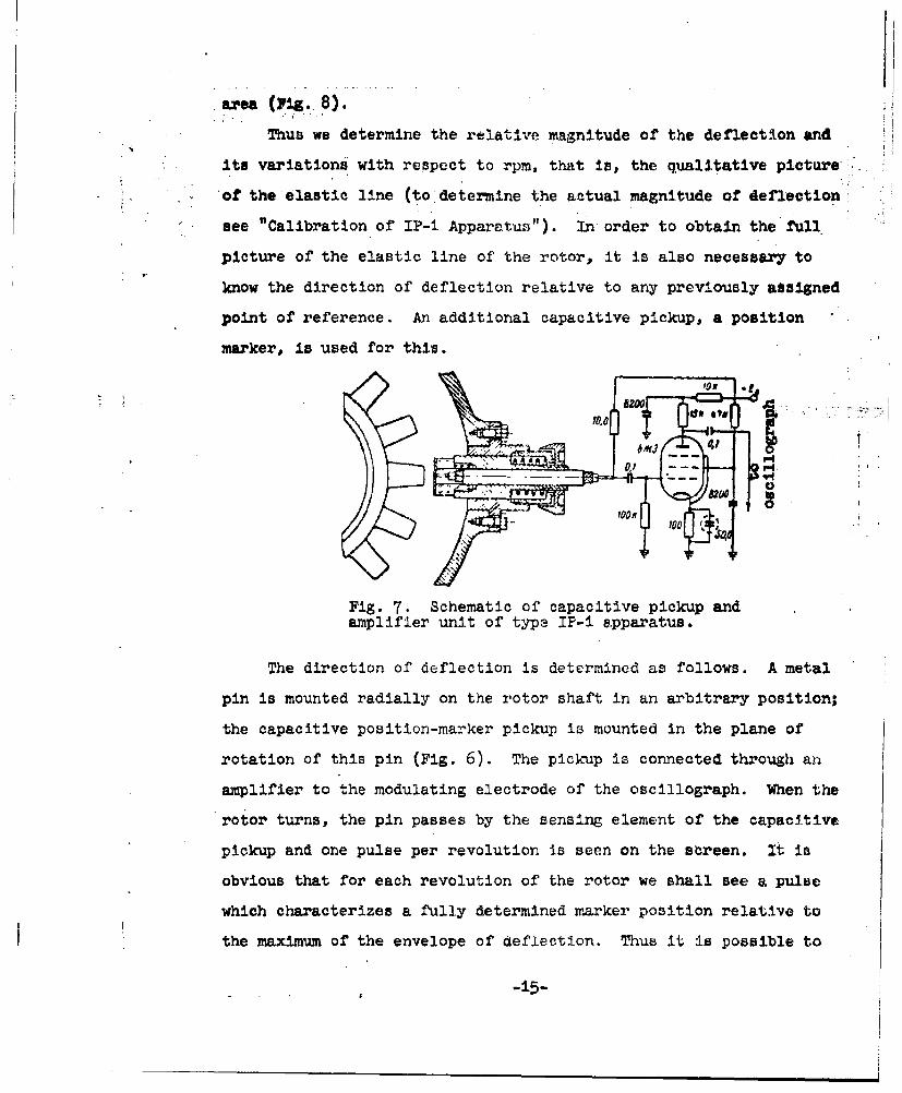
t=U --- -.
Fig. 7. Schematic of capacitive pickup andamplifier unit of type IP-i apparatus.
The direction of deflection is determined as follows. A metal
pin is mounted radially on the rotor shaft in an arbitrary position;
the capacitive position-marker pickup is mounted in the plane of
rotation of this pin (Fig. 6). The pickup is connected through an
amplifier to the modulating electrode of the oscillograph. When the
rotor turns, the pin passes by the sensing element of the capacitive
pickup and one pulse per revolution is seen on the sareen. It is
obvious that for each revolution of the rotor we shall see a pulse
which characterizes a fully determined marker position relative to
the maximum of the envelope of deflection. Thus it is possible to
-±5-

determine with sufficient accuracy (to one blade;) the number of blades
from the maximum of the envelope to the position-marker pulse, i.e.,
to determine with accuracy to one blade the direction of rotor deFlec-
tion in a given plane.'.
a)
d ilillllltt li~llU~iil
b)Fig. 8. Photograph of oscillograph screen.a) in the presence of deflection; b) in theabsence of deflection.
In order to determine the actual magnitude of rotor deflection,
the IP-i apparatus is calibrated.
At the basis of the method lies the balancing under resonance
conditions of the system in the range of operating rpm. Therefore,
in rotor balancing we are interested in its maximum deflection and
the shape of the elastic line. Thereofre, the capacitive apparatus
is calibrated for just those conditions. The calibration technique
is as follows.
Having recorded on the grid of the oscillograph screen the max-
Imum position of the envelope, we depart from resonance by 50 to 00
rpm up or down. In this the amplttude of the envelope decreases or
vanishes. Departing thus from the resonance maximum, we begin to
lead the capacitive pickup toward the stage. The ,signal from the

blades of the stage will increase. Having brought up the signal on
the screen to the former maximum v$1ue of the deflection envelopes
we stop moving the pickup toward the stage and measure the distance
..moved with a micrometer. This value will be equal to twice the
deflection of the rotor in a given plane of measuring.
0to :• Input
to
Pig. 9. Block diagra~m of IP-2 apparatus.
The IP-i apparatus is used when the structure and parameters of
the object to be balanced and the balancing stand allow the apparatus
to be calibrated by the above method. In this case it should be
noted that for balancing it is surffcent to have a qualitative picture
of the deflections; their absolute value~ is important only when
macing other studies.
Thus it is sufficient to equip zhe stand with IP-I apparatus for
balancing at operating rpm.
The IP-2 is a further development of the apparatus for measurin.
the magnitude and direction of de tlectrons. The distigrusehirn
feature of the IP-2 is the Independence of the results of measure-
ments from the speed of the rotor from hundreds of revolutions per
minute to several tens of thousands. Owin to thiav calibration is
considerably simplifiedi.
making~-1 ote tuis

Figure 9 shows a block diagram of the IP.2. A pickup made in
the form of a small inductance coil is mounted at a distance of 1.5
to 2.5 mm from the ends of the rotor blades. The size of the gap is
'determined by the structure of the object, i.e., by the working gap
between the rotor and the housing, and also by the sensitivity of the
pickup.
The inductance of the pickup is part of the high-frequency
oscillator circuit. When a blade passes by the pickup its inductance
changes, and, consequently, the frequency of the h-f oscillator. The
frequency deviation of the latter is a function of the distance
between the pickup and the blade ends, i.e., in the final analysis a
function of the deflection of the rotor shaft and not a function of
the rotor speed.
From the high-frequency oscillator, after passing through a
limiter, the frequency-modulated voltage enters the frequency detector,
from the load of which the voltage, varying in amplitude in accord-
ance with the change in frequency, enters the measuring part of the
circuit and the vertical amplifier of the oscillograph.
The processess taking place in the circuit of the instrument
are shown In Fig. iO, where
Tb _ 60
n is the rotor speed in revolutions per minute; and z is the number
of blades of the given rotor stage.
From Fig. 1O it is apparent that a voltage increment AU, appears
in the presence of deflection. The measuring part of the circuit
measures this increment and thus allows the meter to register the
amount of deflection.
In order to determine tlw -1 o.sation or the so-called "heavy place"
"with an oncillograph, brigh-t ri•trkd are used which correspond to each
* revolution, To accomplish this o. metal p1n is mounted on the rotor.
*. shaft and a capacitive picr-up Iv Jxistalled in its plane of rotation
(see Fig. 9). When the pin passes by the pickup plate, there is a
rapid change in its capacitance, which is transformed into a voltage
pulse. After amplification thl-,i; .oltage enters a slave multivibrator.
From the multivibrator the pulse enters the modulating electrode of
the cathode ray tube.
Balancing at Operating RPM
The possibility of observing changes in rotor deflection in
several places along its length, over the entire range of operating
rpm, allows an effective method of balancing to be put forward.
The basis of this method is balancing with respect to several
driving planes at resonance conditions of the system in the range of
operating rpm of the rotor.
Thus we are interested in the shifting of the rotor, its deflec-
tion at resonance and near--resoy.ance conditions, where maximum vibra-
tion takes place.
From these conditions comes the following balancing order:
i. The setting up of the rotor in the vacuun chamber together
with the framework. The supports should be such that the frequency
characteristic of the rotcr with framework is close to its frequency
... characteristics on the full-scale object.
2. The connect16n of'all necessary systems to the vacuum
chamber and the checking of their operation.
S....-19-

too
pos 0 ion maakeI'ffb)
I 'i~on markery
Fig. 10. Change in frequency arnd voltageof IP-2 unit as a function of deflection.
a) change in frequency of h-f oscillatorin the presence of deflection; b) voltageon oacillogra, h screen in the presence of'deflection; c) voltage on oscillographscreen in the absence of deflection.
~.The switching on of' the. vacuum pump (the required evacuation
of the chamber).
4. The switching on of1 the. oil systems and the current to thc
measuring apparatus by obtaining the required vacuum in the chamber.
5. The :final check of the operation of all systems.
6. The switching on of the drive motor. The atarting rheostat
regulates the smooth starting of' the rotor. When necessary starttnM;
can be in the ar eas of conutant rpm.
-20-

7. While gathering speed. vil-,ations and meter readings are
observed at rated and belowy rated rk,- the most Interesting times
being recorded on film, if necessary.
8. In order to increase the reliability of the results, the
start is repeated without changing the rotor load until stable results
are obtained. This depends upon the structure of the object examined.
9. The resonances of the system lying within the range of
operating rpm of the engine are made apparent by obtaining the
vibratory characteristics of the system along with respect to
revolutions. Taking into account the location of the "heavy places"-
along the rotor stages, at these resonance revolutions we determir . .
the iccation and magnitude (for each stage) of the required balancing
weights.
This method was approved in the study of vibrations of full-*
scale rotors of modern turbo-.Jet engines on a vacuum vibromeasuring
balancing stand. Compressor rotor-s wore balanced the vibration of
which exceeded the allowable ])niJts and which is riot eliminated by
modern factory methods.
As an illustration let us examine the results of the balancing
of a rotor by this method. Tne rotor was balanced on an ordinary
balancing stand with respect to the two outer driving planes; the
remaining imbalance did not Exceed •O gcm.. The engine assembled.
with this compressor rotor showed increased vibration on ihe test
stand. Attempts to eliminate the 'vibration by balancing plates,
which allowed the compressor rotor to be balanced with respect to
the same outer driving planes in the range of operating rpm, did not
give the necessary result.

The rotor was examined .•id :'eubalanced severa.Y times", but each
time the engine was tested onu the ttand, increased vibaration was
,observed, which could not be elimio•ated by plateB.
. -Before sending the rotor to 1--he MVAI, it was again balanced to
40 gcm. The rotor was set up Jn the vacuumn chamber and run up several
times to maximum rpm. As a result, the dependence of' deflections
upon rpm was obtained and t~: v':I:.tory characterirtic of the rotor
in the initial state was taken.,
After processing the data it was established that the system had
two resonance regimes, at 61400 and 7200 rpm (Fig. iha). In this case
the deflection line of the rotor -represented the first oscillation
shape; maximum deflection occurred at about the middle part of the
rotor. Therefore, it war; dc•c.cdcd to balance the rotor only with
respect to the median plane, the thrid stage. It is important to
note that maximum deflection at the middle section was observed at
speeds corresponding to two resonances; the directions of the deflec-
tions in both cases diverged by about 600. Two balancing weights
were hung alternately. The first weight was hung to eliminate the
deflection occurring at 7200 rpm (Fig, iib) and the second to elimi-.
nate the deflection appearing at 6400 rpm (Fig. lic). As a result,
rotor vibration at 7200 rpm was reduced by a factnr of eight, and at
6400 rpm, by a factor of two, without changing the vibration level
at other speeds.
FTD-TT-62-738/i+2+4 -22-

armA
,LI
S '5 . i 5 4S 7 7,5 8t ff-Tpm
Fig, 11. Change In vibration amplitude withrespect to speed at various rotor loads.
a) initial position of rotor; b) with weightqj=250 gcm; 0) with additional weighit q2
-125 gem in a new position.
4 Conclusions
The existing method of? balancing rotors by using two outer
correction planes can lower the level of' vibrations but cannot eli.-
inate their causes and guarantee vibrationlesB engine operation.
The studies showed that the propcoccd method of balancing with
additional (median) correction planes at operating speeds allows
rotor d.fIlectiori to be decreased considerably, and thus rotor stress
and the vibration level are reduced.
On the basis of' the studies made, the following order for engine
rotor balancing is recommended:
1. The separate static balancing n of part in the rotor assembly.
2. Dynamic balancinm at low speed with the two outer driving
Planes.
nlD-TT-62-738/i+2&+ -5
3. Final balancing at ,Iper.Llng rpr. using additional median
Iicorrection planes.
The last two steps can be carrled out on a vibromeaauring bal-
ancing stand, 'which makes It possible to study vibrations in full-
scale gas-turbine engines and their assemblies at operating rpm and
above with negligible expenditure of power.
REFERENCES
i. S. P. Timoihenko. Plates and Shells, GostekhIzdat, -j•49 8•o.
2. N. V. Kelesnik. Static and Dynmamic Balancing, Mashgiz, 1954.
3. S. P. Timoshenko. Theory of Oscillations in Engineering,Oostekhizdat, 1954.
4. B. V. Shitikov. Dynamic Balancing of Rotors, Traneshel-dorizdat" 1951.
5. B. N. Korolev. .Vacuum Technology, Gosenergoizdat, 1958.
FrD-TT-62-738/1+2+4 _24-
________________________i___________________________________I_ ___ __ir__

fD STRIBUTT1ON LIST
DEPARTMENT OF DEFENSE Nr. Copies MAJOR AIR COMMANDS NT, Copiem
APSC
ARO.HEADQUARTERS USAF ASTIA 10AYCIN-3D2
TD-Blb 3BSD (BSF) 1AFFTC (Mr) 1
OTHER AGENCIESOIA
1NSA 2AIn 202!8 2AEC 2PWs IRAND 1
FTD-T- 62-738/+2+42


