AD 601 698 INVESTIGATION OF THE FEASIBILITY OF MANUFACTURING AGGREGATE BY NUCLEAR METHODS lo MISCELLANEOUS PAPER NO. 6.643 Ap$l 1964 Sponsored by U. S. ARMY MATERIEL COMMAND Project No. 4A 022601A880 U. S. Army Engineer Waterways Experiment Station CORPS OF ENGINEERS Virksburg, Mississippi
Transcript
AD 601 698
INVESTIGATION OF THE FEASIBILITY OFMANUFACTURING AGGREGATE BY
NUCLEAR METHODSlo
MISCELLANEOUS PAPER NO. 6.643
Ap$l 1964
Sponsored by
U. S. ARMY MATERIEL COMMANDProject No. 4A 022601A880
U. S. Army Engineer Waterways Experiment Station
CORPS OF ENGINEERSVirksburg, Mississippi
PREFACE
T.,e study dt,.;-' ibed herein was performed by the U. S. Arwy Engineer',ýttrways Experiment Station (WES) during the period April through June
1963 for the U. S. Arnqj Materiel Command (AMCRD-DE-N) as a part of the
p•roject on Military Engineer Application o7 Nuclear Weapons Effects
>s%-arch (M.1EANVIE). The project was under the supervision of Messrs. J. M.
lolatty and R. L. Curry of the WES Concrete Division. Mr. Curry prepared
this report.
Analyse• s of 4he grid photographo to determine par f!c'e Si-e di.trtbu-
tiorn v.ere made by personnel of the WES Soil's Division. tonstructive uug-
,.stion; concerning the report were made b:,! personnel of the Soils and
Nuclear Wenpons Lifects Divisions of WES, Col. E. E. Graves, Jr., and Capt.
,uhn Toman of the U. S. Army Engineer Nuclear Cratering Group, and others.
Col. Alex G. Sutton, Jr.,,CE, was Director of WES, Mr. J. B. Tiffany
was Technical Director, and Mr. Thomas B. Kennedy was Chief,, Concrete Div-
ioion, during the course of the study and the preparation and publication
PART IV: LABORATORY TESTS ........... ..................... ... 11
Specific Gravity and Absorption ................ 11Compressive Sreng......h ...................... 11Laboratory Radioloogical Test Data . .............. 11Particle Shape .............. .......... 12
PART V: AGGREGATE PRODUCTION PROBLEMS .1.............
PART VI: CONCLUSIONS ......................... 16Mechanical Preparation ................................. . l..16Yield .......... ............................. 16Sphericity Ratio ............... ....................... 16Desirable Data ................. ........................ 16
V
SUNMARY
This report covers a limited study of preshot and postshot character-istics of basalt in the area of the Danny Boy nuclear event, to determineif it would be practical to manufacture aggregate for construction purposesby nuclear means.
In this event approximately 20 percent of the ejecta could havebeen made available for use as concrete aggregate by sieving. Secondarycrushing would have produced a greater quantity. Other studies would benecessary to determine the effect of nuclear blasts upon other types ofrock.
vii
INVESTIGATION OF THE FEASIBILITY OF MANUFACTURING AGGREGATE
BL NuCLEAR METHODS
PART I: INTROLUCTION
Background
1. The use of a nuclear detonation to manufacture aggregate appears
to hold considerable promise from the standpoint of economy, based on data
obtained from recent rock-cratering tests conducted at the U. S. Atomic
Energy Commission's Nevada Test Site by Department of Defense/Defense
Atomic Support Agency. From these tests it appears that the aggregate
manufactured by nuclear methods can be classified into two types: (a)
rough aggregate, with no secondary crushing, which is separated into vari-
ous sizes by using only such devices as the rock rake and screening appa-
ratus; and (b) processed aggregate, which has been further manufactured by
screening and crushing in a secondary crushing plant.
Purpose
2. The purpose of this study was to investigate the feasibility of
the use of nuclear methods to manufacture aggregate for construction
purposes.
Scipe of Investigation
3. Personnel of the L. S. Arvy Engineer Waterways Experiment Station
(WES) visited the crater formed by the Project Danny Boy nuclear detonation
in basalt at the Nevada Test Site to examine the ejecta from the blast and
select rock samples for laboratory examination. The detonation had been
made about a year before this inspection, and field readings at the time of
the inspection indicated radiation levels of 5 mr*/hr or less in the ejecta.
No samples were taken within the crater where field readings showed
* Milliroentgens.
2
radiation levels on the order of 10 to 40 mr/?nr.4. The ejecta was inspected to determine rock types and the percent-
age of rock of different size ranges. Also, the total aount of usable
aggregate in the ejecta was estimated by means of a grid overlay. Samples
of small and large rock sizes were then selected and carefully tested for
radioactivity before shipment to WES for laboratory examination. In the
laboratory the specific gravity and absorption characteristics of the rock
samples were determined.
5. The information obtained in this investigation is applicable only
to the ejecta from the Danny Boy crater. Results concerning characteris-
tics of this material were influenced by the rock type, depth of hurst,
fractural frequency, and other 'actors..
3
PART II: TEST AREA AND SAMPLING OPERATIONS
Basalt Crater
6. The Danny Boy basalt crater was formed on 5 March 1962 by deto-
nating a O.i4.2-kt nuclear device at a depth of 110 ft in a 36-in.-diameter
core hole that was stemmed with sand. Photograph 1 shows the crater area
on 29 April 1963. The crater shape resembled an inverted cone. Fig. 1
shows the approximate dimensions of the crater, and the locations of
130'
S- I ..._ ' •- EJECTA
PRESHOT GROUND SURFACE \I / SURFACE GROUND 1.ER0
~~~~~~ 1PP !_-"•• PARENT CRATER
"W - FALLACKEFFECTIVE DEVICE CENTER /
- TRUE CRATER
CROSS SECTION
N
4•4 DISTANCET' FROM
onoQ J o ZiERO
D DENOTES LOCATION OFPRESHOT CORE HOLE GON
00A" 'Ai5 ...... .w
APPARENT CRATER LIP CREST
6 WDH 6
NOTE: MEASUREMENTS WERE ALL * WDH 9APPROXIMATE AVERAGES.
PLAN
Fig. 1. Crater cross section and plan
4
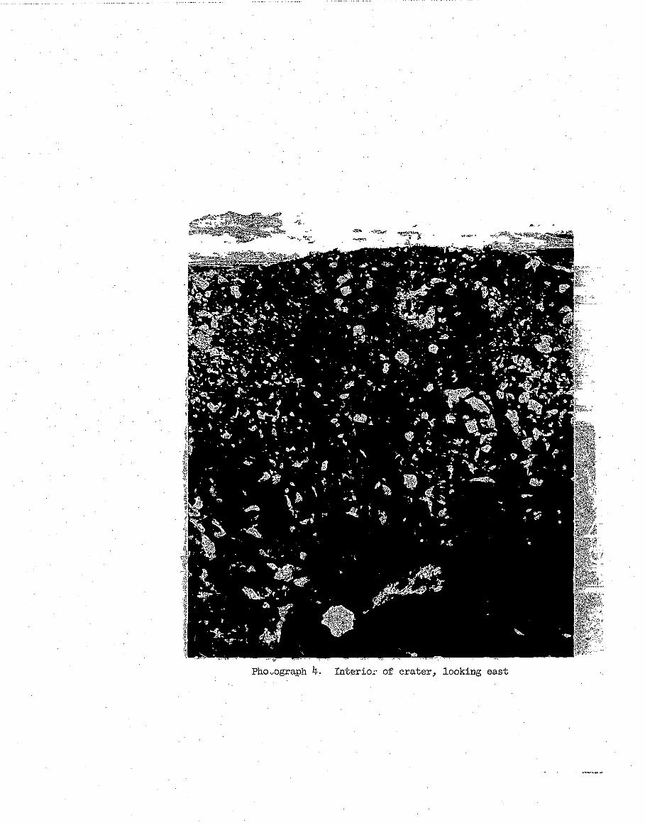
preshot core holes. The apparent depth of the crater was approximately
62 ft. Photographs 2-9 are views of the interior of the crater taken from
eight directions.
Trench and Road Fill
7. To permit a better study of the nature of the explosive effect, a
trench was excavated to ground level from the outer circumference of the
ejecta to the lip of the crater along survey line S670 30'W (see fig. 2).
SLINE -. j
SCALE IN FEET
.0 100 200 300
Fig. 2. Sampling locations
This trench was approximately 10 ft wide at the ground level; distances
from ground zero (GZ) were marked along the center linle of the trench.
Photograph 10 is a view of the trench from directly across the crater.
Using the sides of the trench as a means of determination, it was estimated
that the ejecta piled up to heights varying from 8 to 20 ft above the
5
original ground surface, and tapered down to scattered pieces of rock at
380 to 430 ft from GZ. Some scattered pieces of rock were observed more
than 530 ft from GZ. Even as far as approximately 340 ft from GZ there was
sufficient depth of crushed rock to make sampling practicable.
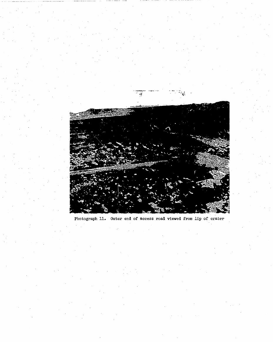
8. An access road of earth fill had been constructed to the edge of
the crater along survey line S670''E (fig. 2). Photograph 11 shows the
outer end of this road and illustrates scattering of the rock in the area
beyond approximately 380 ft from GZ.
Fragment Sizes
9. The rock fragments in the ejecta and within the crater were in-
spected, and the diameter of some of the larger fragments was measured.
The largest fragments were in the crater, some of them being approximately
20 ft in diameter. However, some of the fragments in the ejecta measured
as much as 15 ft in diameter. The presence of caliche or calcite on a
majority of the particle surfaces reflected fragmentation along joint
planes. An estimate of the percentage of the various sizes of fragments in
the ejecta, made from a visual inspection of the surface, was as follows:
Approximate PercentFragment Diameter by Volume
>3ft 303 ft to 7 in. 307 in. to 3 in. 253 in. to 1-1/2 in. 10< 1-1/2 in.
Total 100
This estimate of the sizes of aggregate observed at the surface is included
in the report only to reflect the percentage distribution of sizes not
covered by the actual counts from photographs described below. Some of the
larger fragments are shown in photograph 12, and some of the smaller ones
in photograph 13.
10. Photograph 14 illustrates a 1-ft-square grid overlay laid along
the ejecta su'face along the south line. From photographs of this type,
particle counts of the various sizes of fragments were made; percentages of
particle distribution were determined; and cumulative percentages passing
sieve sizes 12, 9, 6, and 3 in. were calculated. This study showed that
6
there was layering of different sizes, and that observations of the surface
of the ejects did not necessarily indicate true particle percentages in the
total ejecta.
11. The WES Geology Branch provided other sequential, overlapping
photographs of the surface of the crater along radial lines extending: (a)
east, (b) north, (c) west, and (d) slightly east of south (this line was
25 to 30 ft east of true south at a distance of about 130 ft from GZ).
Percentages finer than arbitrarily selected sizes and based on the counts
along these lines, cumulated with distance from GZ, are plotted in fig. 3.
! 80 O--0-0 FINER THAN 12-IN. SIEVE" b � FINER THAN S-IN. SIEVE
O O-O FINER THAN 6-4N. SIEVEWI- - FINER THAN '3-N. SIEVE
U
60-
61
40- I i I A 4 A ' - 1 I i I I A I A A
IU IN 17S I 0 I 21 1 3 271 2 315 338 388 375
DISTANCE -11 GROUND ZERO IN FEET
Fig. 3. Cumulative average particle size distribution atdesignated distances from ground zero
12. In determining particle distribution, particle sizes were arbi-
trarily designated as follows: size A, larger than 12 in.; size B, 9 to
12 in.; size C, 6 to 9 in.; size D, 3 to 6 in.; and size E, smaller than
3 in. Theoe sizes refer to the smaller diameter (width) on bulky particles
and to the longest dimension on large slender particles. These dimensions
refer to plane dimensions only. For fig. 3, percentages were corrected for
thickness of particles by assuming the particles to be nominally spherical
in shape.
13. Sheets were devised for recording the particle size count in a
10- by 10-ft grid pattern. An example of such a sheet is shown in fig. 4.
On this standard sheet a count of particle size was made for each square
foot and each running foot Plong the center line by averaging the
STATIONIFROMGZ 1211
BCD
c 8~D 24
%lo n,"o 8 8t 80 " B 7 P, \.n 00 000"c 8D 17
;5& i5ý t5 g wu sU B 8 "w8 on( 8 9\ z2 8 \110 00 00 ~c 16 0 ,
D 18j______BE 37T __
m v t t mU0w m 0w~ td tJ0w >A 19 Mtn ý-vvt
tLii 0I O ; 6wxIC 170I D 18
ID , )ý o ý. M~~ L4 ~W \ WW )
0 C 25ID 27
C+%n0 \.nIn 0 " f0 0 \. cB 110 0 00 00o
oD 27
c 6D 23
0 La 0 '6B09S8
0 c 9O ~ O ~ W W
I- it 6oRI41
2 19
0000 H~
0H IA l(U (I lclt
H i~ 0 ~ -P(Ut
8
distribution for the 5 sq ft on each side of the center line.
14. A count was made as follows. For a given square foot, the
particle size could be estimated by comparison with the 1-ft grid. Each
particle within the square foot was designated A, B, C, D, or E, and then
an estimate was made of the percentage of the 1 sq ft that the particle oc-
cupied. Usually this count started with the largest size and proceeded
downward so that the remaining percentage (i .e. 100 minus the combined per-
centage of A, B, C, and D particles) was assigned to the size E particle.
A given square foot recorded as A 30, B 10, C 20, D 20, and E 20 meant that
30 percent of the square foot was occupied by a size A (12 in. or larger)
particle; 10 percent was occupied by a size B particle; etc.
Rock Types
15. The rock fragments at the site included the types designated as
subandesite, caliche or calcite, and basalt with small-, medium-, and large-
size vesicles. Field geologists at the site noted layering of the ejecta
by types with approximately the top 1-1/2 ft being called "dense (subande-
site)," the next 3 to 4 ft called "vesicular," and the next 3 to 4 ft
"dense," bNlov which weathered browner rock occurred. The layering noted
was determined by geologically mapping the walls of the trench, and its
significance or relation to the preshot geology will be covered separately
in a report to be published at a later date (Postshot Exploration of the
Danny Boy Crater). Along surface planes of many fragments there was a pro-
nounced layer of caliche or calcite (this indicated that fragmentation had
occurred along Joint planes), and there were some independent fragments of
this material scattered through the ejecta. The percentages of the types
of rock in the ejecta were estimated to be as follows:
Approximate Percent7ype of Rock by Volume
SSubandesite 10Basalt with small-size vesicles 50
(1/16 to 1/4 in. in diameter)Basalt with medium-size vesicles 22
(1/4 to 1/2 in. in diameter)Basalt with large-size vesicles 17
(diameter over 1/2 in.)Caliche 1
Total 100
9
Photograph 15, a close-up of the Danny Boy crater ejecta, clearly illus-
trates basalt with different sizes of vesicles, and caliche along surface
planes of some fragments. Particles of light gray subandesite are not
readily distinguished in the photograph.
Samples
16. Forty bags of rock sieved to pass a 1-1/2-in, sieve were se-
lected from the ejecta for laboratory testing. One bag was collected from
each of locations 1 through 40 shown in fig. 2. These locations, five ineach of eight areas spaced around the crater, were approximately 160, 190,
210, 240, and 270 ft from GZ.
17. Twenty-four large and 18 smaller pieces of rock were selectedfor laboratory testing from the area bounded by ABCD in fig. 2, line CD
being 205 ft from GZ, line AB being 280 ft from GZ, arid lines AD and BC
being approximately 50 ft from the center line of the trench at S67030'W.
The 24 large pieces of rock, each weighing 75 to 115 ib, were selected
to approximately represent on a percentage basis the rock types present inthe ejecta. The 18 small pieces of rock, each approximately 3 to 6 in. in
diameter, were selected to represent small aggregate of the six different
rock types listed below, three pieces for each type. The rock types were
selected in an attempt to cover the ranige of specific gravities thoughtlike'Ly to be present in the ejecta. These types are referred to herein as(a) basalt with small-size vesicles, (b) weathered basalt with small-size
vesicles, (c) subandesite, (d) caliche, (e) basalt with large-size vesicles,
and (f) basalt with medium-size vesicles.
10
PART III: FIELD INSPECTIONS FOR RADIOACTIVITY,
Sieved Samples
18. The 40 bags of rock which had been sieved over the 1-1/2-in.
sieve were monitored at the Danny Boy test site for radioactivity before
shipment to WES for laboratory testing. The radiation detection instru-
ments were placed in and around the rock fragments in each bag, and gana
radiation readings were 3 to 5 mr/hr.
Single Fragmnts
19. The 24 large fragments and the 18 pieces of 3- to 6 -in. rock
were also monitored before shipment to WES. These fragments showed gamna
readings of 0.5 to 2 mr/hr.
PersonLel Check
20. The personnel who selected the samples were monitored daily with
dosimeters to detect radioactivity pickup. The daily readings varied from
30 to 50 mr/hr.
ShtMdent Inspection
21. The material was inspected after it had been loaded on a truck
Just prior to shipment from the Nevada Test Site. The highest reading in
or around the rock was 6.5 mr/hr gama, and 40 milliradians/hr ganna and
beta. In the truck cab, the reading was 0.1 mr/hr gamma.
"! ~11
PART IV: LABORATORY TESTS
Specific Gravity and Absorption
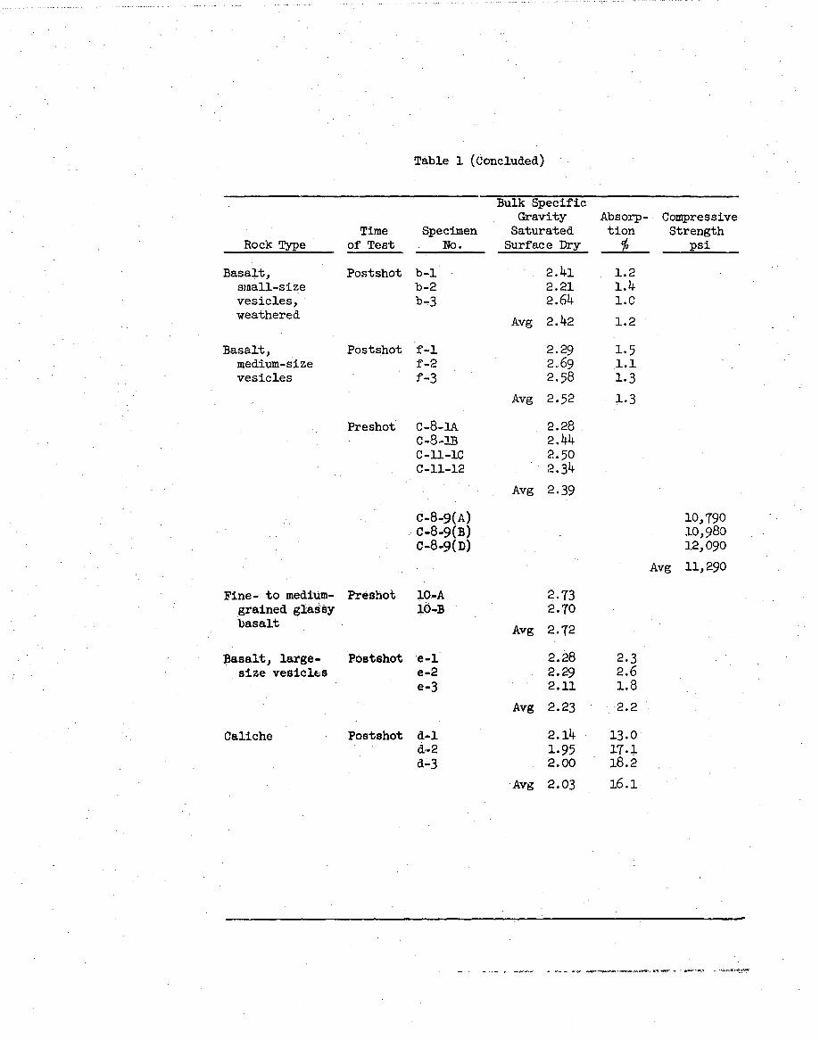
22. The eighteen 3- to 6-in. fragments were tested for saturated
surface dry specific gravity and absorption at WES. Results are given in
table 1 as postshot test data. The preshot specific gravities listed in
the table were taken from a previous report. The variations in the spe-
cific gravities are due to a number of causes, one being the considerable
variation in rock structure within the individual rock types. Also the
amount of weathering, and vesicle distribution and size varied between
Srock fragments. However, the same general types of rock were tested in
the preshot and postshot studies, and except for the ca.iche, the specific
gravity and absorption results indicated that these rocks would probably
be suitable for use as concrete aggregate.
Compressive Strength
23. A nunber of preshot tests for compressive strength had been made
on rock cores from core holes designated by WDH numbers in fig. 1, page 3,
and the results have been reported in a previous report. The comressive
strengths indicate good mound rock (see table 1).
Laboratory Radiological Test Data
24. In preparation for further laboratory testing planned for the
ejecta material, it was necessary to determine (a) the dust hazard that
would result from crushing and pulverizing processes, and (b) necessary
waste-disposal procedures. This necessitated radiological studies of
genma, beta, and alpha radiations. WES personnel determined the gamma and
beta radiations to be essentially the same as those measured in the pre-
shipment check at the Nevada Test Site.
25. Reynolds Electrical and Engineering Co., Inc. (see reference 2),
cites thb April 1958 Addendum to National Bureau of Standards Handbook
No. 59 as source of the following maximum permissible doses of radiation:
12
Maximum Peimissible DoseProvisional* Emergency
Critical Organ Occupational Occupational (Once in a Lifetime)
Total body 5 rem**/yr 12 rem/yr 25 remMost individual organs 15 rem/yr ---
Thyroid or skin 30 rem/yr - -.-..
* The dose indicated in this column is allowable if the previous exposurehistory is known. The records of previous exposures must show that theadditinn of such a dose will not cause the individual to exceed the age-prorated allowance 5 X (n - 18), where n = age in years and must begreater than 18.
** A rem is a roentgen equivalent for man.
26. The radiations picked up on the dosimeters and the beta-gamna
counts were so small as to all but preclude any possibility of the maximum
permissible dose being attained, even from daily contact with the material
from the Danny Boy crater for a period of a year from the time it was
sampled.
27. Small particles were found which had a fused appearance and
higher beta-gamma radiation than the average fragments. These were sus-
pected of having a high alpha radiation. Further inspections by repre-L
sentatives of the Atomic Energy Commission, the Edgewood Arsenal, and the
Office, Chief of Engineers, revealed that for selected samples the gamma
plus beta radiation was approximately 400 milliradians/hr. It was decided
that the WES laboratory was not equipped to handle this material safely on
subsequent crushing or properly dispose of the waste resulting therefrom.
The material was therefore shipped back to the Nevada Test Site, and the
area where it had been stored and tested at WES was scrubbed and determined
to be radioactively safe.
Particle Shape
28. Detailed study of the particle shapes was not made because of
the limited scope of the study; however, the fragments looked the same as
those which would be obtained from use of conventional explosives in
basalt. The edges of the pieces were sharp, and while the larger pieces
tended to be blocky, as can be seen in the photographs included herein,
the pieces smaller than about 3 in. tended to be splintery in shape, with
13
tendency toward splinteryness increasing with decreasing particle size. It
is well known from many studies of operations involved in fragmenting brit-
tle solids (crushing, grinding, comminution) that the tendency of the frag-
ments to have a flat or an elongated shape increases with the reduction
ratio; i.e. the product of any single reduction operation, if graded, will
be progressively flatter and more elongated •he smaller the particle size.
14
PART V: AGGREGATE PRODUCTION PROBLEMS
Decay Schemes
29. Fig. 3.2 in Project Danny Boy Report POR-1819 indicates that the
gama dose-rate in an area just outside the crater was 1000 r/hr at H + 1
hr as determined from ground-survey measurements and extrapolation by the
T-13, formula. Fig. 3.9 in the same report indicates a gamia dose-rate of
3000 to 3200 mrhwr (3.0 to 3.2 r/l4i) in the same area at D + 15 and D + 16
days, again determined from ground-survey measurements. A formula for the
determination of rate of disintegration varied between A T-1.3 and
A • T as expressions of necessary calculations, where A = a constant
and T = the time in hours after explosion. The actual exponent should
probably be slightly higher than the determined value due to the fact that
shielding influenced the film detector instruments used in the crater. ThL
radioactivity of the aggregate is of concern, and might be theoreticall,-
calculated, but this would not be practicable for prediction purposes at
the present time. The decay curve of the aggregate would depend on the
composition of the nuclear explosive, the efficiency of the particular
blast involved (both the fission products and the unused original material),
the characteristics (such as chemical composition) of the medium in which
the blast took place, and perhaps other factors.
Size Sparation
30. Suitable equipment is needed for the separation of the aggregate
size groups in the ejecta from a nuclear detonation. Rock rakes mounted on
truck tractors have been used for similar purposes, and are available with
spacings between teeth as small as 6 in. By using a roAk rake with a 6-in.
clearance, those fragments smaller than 6 in. in diameter could be sepa-
rated from the larger fragments of the ejecta. From the planometer per-
centage values determined from aerial photographs, it is estimated that the
bulk volume of the ejecta from the Danny Boy crater was 56,000 cu yd. From
fig. 3 it can be estimated that approximately 20 percent of this, or l,200
cu yd, could be separated out by the 6-in. rock rake. The estimate of 20
percent was based on total of the area under the curve.
15
Crushing Equipment
31. Various types of crushers are available to the U. S. Army Corps
of Engineers for further crushing ejecta from nuclear shots or materials
separated therefrom by rock rakes. The Department of Mechanical and
Technical Equipment, U. S. Army Engineer School, Fort Belvoir, Virginia,
lists manuals for the following:
Maximum Rock SizeType Crusher Crusher Will Take, in.
W-50 13 by 3825-ton-per-hr 13 by 2275-ton-per-hr 18 by 34200- to 400-ton-per-hr 28 by 40
From fig. 3 it can be seen that approximately 20 percent of the ejecta from
the Danny Boy crater has a fragment diameter between 6 and 12 in. This
size rock could be crushed with a 25-ton-per-hr crusher to pass a 6-in.
sieve.
16
PART VI: CONCLUSIONS
Mechanical Preparation
32. Aggregates for use in base course, and asphalt and concrete con-
struction could be manufactured by nuclear blast, after which a rock rake
and a crusher would facilitate separation intc sieve size groups.
Yield
33. The Danny Boy basalt cratering event discussed herein yielded
approximately 56,000 cu. yd of rock fragments, of which at least 11,200 cu
yd could be manufactured into aggregate by using a rock rake and crusher.
It would be necessary to ensure that radioactivity had decayed to a low
enough level so that construction or subsequent maintenance of roads or
structures containing the aggregates would present no health hazard. The
reader should keep in mind that the very limited findings reported herein
apply only to a cratering event in basalt. An event of equal yield in
granite, limestone, or other rock would probably produce different results.
The amount of usable material as well as size and shape of Zragments would
vary with rock type and depth of burst. Particle shape and size would de-
pend upon the bedding planes, Joint system, and other structural features
of the rock. Suitability of the processed rock for use in concrete would
necessarily depend upon the rock type and the crushing characteristics.
Sphericity Ratio
34. The presence or absence of a correlation between rock type,
particle size, and partic.e shape (sphericity ratio) along traverses from
the crater rim should be established. Rock fragments should be examined
petrographically in the laboratory, particularly for schistosity, to estab-
lish reasons for the size and shape distribution of the rock fragments
about the crat._r.
Desirable Data
35. Cores extracted from large fragments of debris after the event
17
would have afforded an idea of the strength of the rock after the blast.-
Petrographic examination of thin sections of the preshot and postshot
material under the microscope would have afforded a qualitative idea of
how the strength of the rock was affected. However, such tests were beyond
the scope of this investigation.
18
PART VII: RECOMMENDATIONS
Completion of Present Work
36. It is recommended that the investigation described in this
report, and prosecuted only through its preliminary phases, be completed
by determining through sieve analysis in the field the particle size dis-
tribution 'vrithin usable size ranges and particle shape, and through petro-
graphic examination in the labcratory the macroscopic evidence of altera-
tion caused by blast that might affect suitability of the aggregate for
construction purposE Concrete specimens utilizing such aggregate should
be made for strength testing in addition to the standard tests to determine
suitability of aggregates. The radioactivity of the aggregates and the
concretes made with them should be determined.
Future Work
37. IT is recommended that when a cratering shot is planned in
sound hard rock sufficient cores be taken prior to detonation to permit
thorough examination and processing into aggregate to compare with material
resulting from the blast that appears to be suitable aggregate.
38. It is believed that a complete study of aggregate production
potential by nuclear methods should include:
a. A detailed study of block size distribution to determinevariations as a function of depth of burst.
b. A detailed study of block size distribution to determinedependence upon preshot geologic conditions such asfracture frequency, Jointing, type of rock, etc.
I
19
REFERENCES
1. Samuel Glasstone, ed., The Effects of Nuclear Weapons. Prepared bythe U. S. Department of Defense, published by the U. S. Atomic EnergyCommission, June 1957.
2. , Emergency Radiation Monitoring Team Training Manual.Radiological Safety Division, Industrial Health and Medicine Depart-ment, Reynolds Electrical and Engineering Co., Inc., Mercury, Nev.,November 1959.
3. , Atomic Radiation, Part II, Monitoring, Radiation Protec-tion, Radioactive Shipment, Waste Disposal. Prepared by RCA ServiceCo., a division of Radio Corporation of America, Government ServiceDepartment, Camden, N. J., 1962.
4. U. S. Army Engineer Waterways Experiment Station, CE, Project Daioy: Petrographic Examination and Physical Tests of Selected Cores
Miscellaneous Paper No. 6-570, Vicksburg, Miss., january 1963-.
'X
Table 1
Laboratory Test Results
Bulk SpecificGravity Absorp- Compressive
Time Specimen Saturated tion StrengthRock T•pe of Test No. Surface Dry % psi