A-I236 TIPPEYTS-ASSET-CARTHY-TATTON NEW YORK F, 6 32 AD-A112 ~ ST. LAWRENCE SEAWAY ADOITIONAL LOCKS STUOY. OTECHNICAL REPORT..ETC(U) MAR 81 T BOBAL DACWa9-60-C-0o02 UNCLASSIFIED NL Ill" I'l"' 2II IIII MENOMONEEIIII QIIIIIIIM, IIIIIIII
Transcript
A-I236 TIPPEYTS-ASSET-CARTHY-TATTON NEW YORK F, 6 32AD-A112 ~ ST. LAWRENCE SEAWAY ADOITIONAL LOCKS STUOY. OTECHNICAL REPORT..ETC(U)MAR 81 T BOBAL DACWa9-60-C-0o02
UNCLASSIFIED NL
Ill" I'l"'2II IIII
MENOMONEEIIIIQIIIIIIIM,IIIIIIII
11111 i ' M25 25
11II11 I FI In- __1w11 _ 11.6.1 2 2
. 0 111L1
OHI 1.11
MICROCOPY RESOLUTION TEST CHARTNATIONAL BUREAU Of STANDAROS 1963-A
ST. LAWRENCE SEAWAY
oADDITIONAL LOCKS STUDY
GEOTECHNICAL REPORT
DEPARTMENT OF THE ARMYBUFFALO DISTRICT, CORPS OF ENGINEERS A
BUFFALO, NEW YORK ,
LA MARCH 1981 /
.. t~a I- '-
SECURITY CLASSIFICATION OF THIS PAGE (When Dja Entered)DOCUMENTATION PAGE READ INSTRUCTIONS
REPORT BEFORE COMPLETING FORM
1. REPORT NUMBER 2. GOVT ACCESSION NO. 3. RECPNTS CATALOG NUMBER
4. TITLE (md Subtitle) S. TYPE OF REPORT & PERIOD COVERED
St. Lawrence Seaway Additional Locks Study: FinalGeotechnical Report. 6. PERFORMING ORG. REPORT NUMBER
7. AUTHOR(&) 8. CONTRACT OR GRANT NUMBER(&)
Thomas Bobal DACW49-C-0002
9. PERFORMING ORGANIZATION NAME AND ADDRESS 10. PROGRAM ELEMENT. PROJECT, TASKTippetts-Abbett-McCarthy-Stratton (TAMS) AREA & WORK UNIT NUMBERS
Engineers, Architects and Planners, TAMS Bldg. Work Order No.1655 Third Ave., New York, N.Y. 10017
II. CONTROLLING OFFICE NAME AND ADDRESS 12. REPORT DATE
U.S. Army Engineer District, Buffalo March 19811776 Niagara St. 13. NUMBER OF PAGES
Buffalo. N.Y. 14207 13014. MONITORING AGENCY NAME & ADDRESS(If different from Controlling Office) 15. SECURITY CLASS. (of this report)
UnclassifiedISa. DECL ASSI FI CATION/DOWNGRADING
SCHFDULE
16. DISTRIBUTION STATEMENT (of this Report)
Distribution unlimited.
17. DISTRIBUTION STATEMENT (of the abstract entered In Block 20, If different from Report)
Il. SUPPLEMENTARY NOTES
19. KEY WORDS (Continue on reverse aide If neceaery and Identify by block number)
Eisenhower Lock Boring DataSnell Lock Soil TestingRegional Geology Rock TestingSubsurface Exploration St. Lawrence Seaway
7 ABSt"RACT - reverse .ta I n 'weev d Iden'tify bv block numberl
,, This report presents geotechnical data used to assist in the selection of
future additional lock and channel locations at four proposed alternativesites along a section of the St. Lawrence Seaway. The proposed alternativesinclude: VTwinV locks at the existing Eisenhower and Snell locks, a singlehigh-lift lock with the construction of a new channel, and an additional locknear Iroquois Dam at Point Rockway with construction of a new channel. All theproposed alternative sites are located within the territory of the United
States along the St. Lawrence Seaway stretching from near Iroquois Dam
.DO JM 1473 EDITION OF I NOV 611 OBSOLETE
SECURITY CLASSIFICATItON OF THIfS PAGE (When Date Entered)
I -l- - --
SECURITY CLASSIFICATION OF THIS PAGE(WIEM Data Bnter d)
downstream to the eastern tip of Cornwall Island near Cornwall, Ontario.Three of the sites, Eisenhower and Snell "Twins" and the high-lift arelocated at the eastern end of the area, northeast of Massena, New York; andthe fourth site, Iroquois-Point Rockway, at the western end near Waddington,New York.
The report presents data from a review of literature and includes sub- -
surface and geophysical exploration data, observations arrived at from on-site reconnaissance and discussions with individuals familiar with the areasin question, examination of existing rock core samples previously taken atsome of the proposed sites, summaries of field and laboratory testing andgeologic profiles and sections based on data from previous subsurfaceexploration programs. < -7
Substantial geotechnical data was obtained from investigations conductedfor the existing Eisenhower pnd Snell Locks. A large portion of this datawas obtained at locations wy ich are in the areas of the proposed Eisenhowerand Snell "Twin" Locks. Data regarding subsurface conditions for the Iroquois-Point Rockway and high-liftsites are very limited and sketchy.
5.1 Soil Testing 575.2 Rock Testing 605.3 Pressure Testing 62
6 GEOTECHNICAL ASPECTS 64
7 CONCLUSIONS 68 @
REFERENCES 70 INSPECTED
TABLES Accesn cn For
1 Stratigraphic Units in Bedrock D I2 T2 Summary of Boring Data - Eisenhower3 Summary of Boring Data - Snell! ., .,
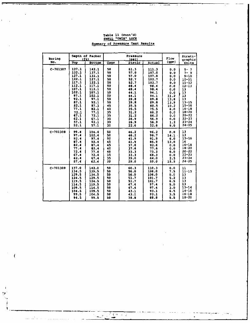
4 1940-41 Survey - Seismic Velocities5 1970 Survey - Seismic Velocities6 Test Data Summary - Eisenhower7 Test Data Summary - Shell8 Summary of Rock Core Tests - Eisenhower9 Summary of Rock Core Tests - Snell10 Summary of Pressure Tests - Eisenhower11 Summary of Pressure Tests - Snell
FIGURES
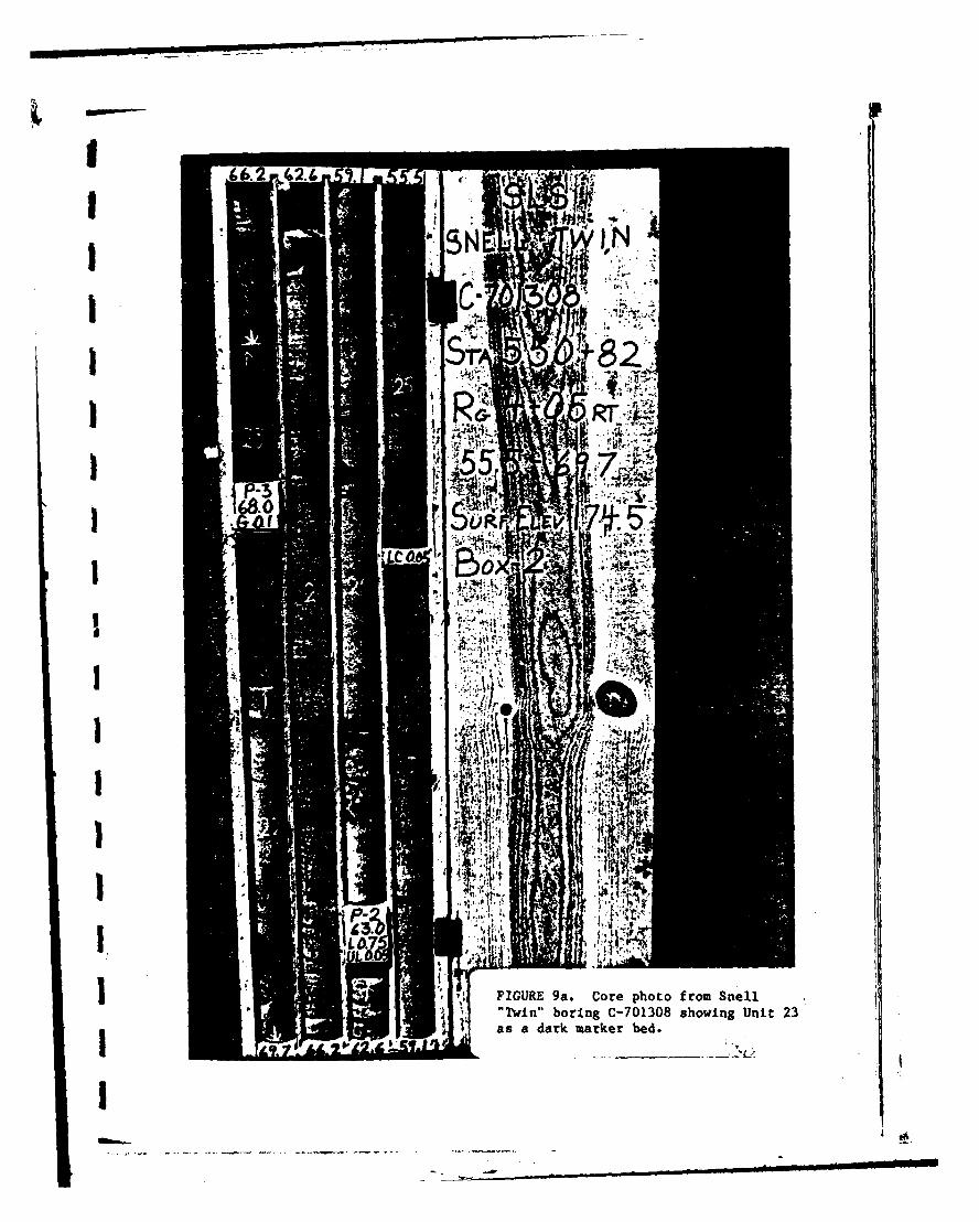
1 St. Lawrence Valley Physiographical Province2 Seismic Risk Map3 Top of Rock Contour Map - Snell4 Till Isopach Map - Eisenhower5 Top of Rock Contour Map - Eisenhower6 Core Photos - Eisenhower7 Core Photos - Eisenhower8 Core Photos - Snell9 Core Photos - Snell
14 Geologic Profile C-C Vicinity, High-Lift Lock Alternative
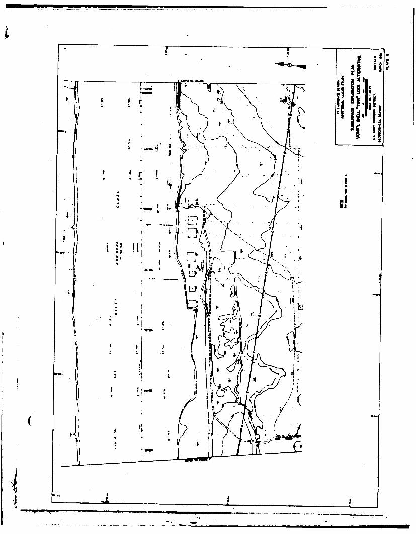
15 Subsurface Exploration Plan Vicinity, Iroquois Lock-Point Rockway Alternative
16 Geologic Profile D-D Vicinity, Iroquois Lock-PointRockway Alternative
PREFACE
The geotechnical report was prepared by Tippetts-Abbett-McCarthy-Stratton, (TAMS) Engineers, Architects and Planners, undercontract No. DACW49-80-C-0002, Work Order No. 1 for the U. S.Army Engineer District, Buffalo.
For the preparation of this report, the Buffalo Districtfurnished in preliminary rough draft form a number of theplates and figures, the laboratory test results, geophysicalsurveys, drilling logs and pressure test data.
Mr. Thomas Bobal of TAMS prepared the report under the guidanceof Mr. Harvey Feldman, Project Study Manager. Mr. Mel Hill,Project Manager for the Corps, reviewed the work by TAMS underthe supervision of Mr. T. A. Wilkinson, Chief, GeotechnicalSection. All Corps work was under the direction of Mr. J. A.Foley, Chief, Design Branch and Mr. Donald M. Liddell, Chief,Engineering Division. Lt Col. Thomas L. Braun, Deputy DistrictEngineer, was the Contracting Officer.
(t
"-']' e l m i ~ i4
1. INTRODUCTION
The purpose of this report is to present geotechnical data
to assist in the selection of future additional lock and
channel locations at four proposed alternative sites along a
section of the St. Lawrence Seaway. The proposed alternatives
include: "Twin" locks at the existing Eisenhower and Snell
Locks, a single High-Lift lock with the construction of a new
channel, and an additional lock near Iroquois Dam at Point
Rockway with construction of a new channel. All the proposed
alternative sites are located within the territory of the
United States along the St. Lawrence Seaway stretching from
near Iroquois Dam downstream to the eastern tip of Cornwall
Island near Cornwall, Ontario. Three of the sites, Eisenhower
and Snell "Twins" and the High-Lift are located at the eastern
end of the area, northeast of Massena, New York (See Plate 1)
and the fourth site, Iroquois-Point Rockway, at the western end
near Waddington, New York.
The report presents data from a review of literature and
previously submitted reports, includes subsurface and geophysi-
cal exploration data, observations arrived at from on-site
reconnaissance and discussions with individuals familiar with
the areas in question, examination of existing rock core
samples previously taken at some of the proposed sites, summa-
ries of field and laboratory testing and geologic profiles and
sections based on data from previous subsurface exploration
programs.
-1-
Substantial geotechnical data was obtained from investiga-
tions conducted for the existing Eisenhower and Snell Locks. A
large portion of this data was obtained at locations which are
in the areas of the proposed Eisenhower and Snell "Twin" Locks.
Data regarding subsurface conditions for the Iroquois-Point
Rockway and the High-Lift sites are very limited and sketchy.
2. REGIONAL GEOLOGY
2.1 Physiography
The project area under consideration is located in the
St. Lawrence Lowland, which forms the northern section of the
St. Lawrence Valley physiographic province. The lowland is a
broad area, less than 1,000 feet in altitude, bordered on the
north by the Laurentian plateau and on the south by the uplands
of the Adirondack province, where elevations average between
1,000 and 2,000 feet.
On the basis of the varying topography found to the south
of the international boundary, the St. Lawrence Lowland can be
subdivided into seven fairly distinct subsections (Figure 1).
Most of the southwestern half of the lowland, including the
Western Tableland, Frontenac Axis, and Black Lake Tableland
Subsections, is characterized by: 1) the rare occurrence and
small bulk of the till deposits; 2) the large areas of
exposed bedrock; 3) the close relationship of the surface
topography to bedrock structure; and 4) the predominance of
lacustrine sediments which lie directly on the bedrock.
By contrast, the northeastern half of the lowland -
roughly that area northeast of a line connecting Ogdensburg and
-2-
4_ , mn |U
Canton - has widespread deposits of till with only rare exposures
of bedrock. Surface topography is controlled by the glacial de-
posits rather than the bedrock.
For the most part, the area is underlain by flat to gently
dipping Paleozoic sediments, the erosion of which has formed
the lowlands. The region underwent peneplaination during the
Tertiary, followed by uplift and degradation of the softer
rocks to flat-bottomed lowland. Over this late Tertiary
erosion surface, the Pleistocene glaciers spread their deposits.
A gently rolling surface of low relief characterizes most
of the area. Elevations range from around 150 feet in the
northeast near Cornwall to more than 500 feet on some hilltops
near Potsdam and Norfolk. The average relief over distances of
a mile or less is about 30 feet.
Drainage of the area is controlled by the St. Lawrence
River. It flows northeastward 270 miles from Lake Ontario to
Quebec and another 370 miles from Quebec to Anticosti Island in
the Gulf of St. Lawrence.
The St. Lawrence River has only occupied its present
location since the retreat of the last Wisconsin glacier and
the recession of the Champlain Sea, some 5,000-6,000 years ago.
It has, therefore, not had enough time to cut a valley for
itself, but simply follows a connecting chain of glacially-
formed depressions, flowing around and among the small bedrock
hills at its western end and the hills of glacial till farther
east. Consequently, it is ,narad and, prior to construction
-3-
m n I i Ii
-~~ - -~- ~~r7 ~ -,,...-- - - - -
of the St. Lawrence Seaway, was studded with the now-submerged
Galop and Long Sault Rapids.
Due to the regulating effect of Lake Ontario on the
surface water discharge, the river is not subject to extreme
floods and low water as are normal rivers. By eroding fine
material which its normal flow can handle, it has left behind
coarser material which acts as an armor protecting the banks
from further erosion. Because of this, the St. Lawrence has
accomplished relatively little erosion for so large a river.
The three major tributaries to the St. Lawrence from the
south - the Grass, Raquette and St. Regis Rivers - also follow
valleys made for them by the pattern of glacial deposits. All
flow northward off of the Adirondack highlands and then turn
eastward upon approaching the St. Lawrence trough to follow
the elongate depressions between morainal ridges for several
i..iles before joining the main stream. Many smaller streams
flow into these rivers or directly into the St. Lawrence and
show a great deal of seasonal fluctuation in discharge.
Extensive marshlands are found throughout the area but there
are few natural lakes.
2.2 Surficial Geology
The bedrock in the northeastern half of the St. Lawrence
Lowland is overlain by a blanket of glacial drift which varies
in thickness up to more than 200 feet in places. These uncon-
solidated deposits were laid down in late Pleistocene time
during and after the Wisconsin glaciation. The deposits
-4-
comprise: (1) till laid down by the glacial ice; (2) clay
and other materials deposited in standing bodies of water
during and after melting back of the ice; (3) deposits formed
by the modification of the till and other sediments; and (4)
materials laid down after the large bodies of standing water
had been drained. The most complete sequence of these deposits
can be seen near Lake St. Lawrence.
On the basis of till fabric and the striations found on
underlying rock surfaces, two separate glacial episodes can be
identified. The earlier one, the Malone glaciation, moved
southwest up the St. Lawrence valley and then spread over the
Adirondacks. The Malone has been correlated with the Cary
sub-stage of the Wisconsin standard section in the midwestern
United States. The later Fort Covington invasion crossed the
valley from northwest to southeast and extended only as far as
the northern flank of the Adirondack upland. It has been
correlated with the Valders substage, the final Wisconsin
advance.
With the retreat of the Fort Covington glacier and the
formation of an ice barrier in the lower St. Lawrence valley, a
fresh-water proglacial lake (Lake Fort Ann) was created cover-
ing most of the area. A break in the ice barrier drained the
lake, and the subsequent eustatic rise of sea level (due to the
inflow of meltwaters from the retreating glaciers) permitted
flooding of the lowland by marine waters of the Champlain Sea.
The earth's crust, which had been deformed under the enormous
-5- $
weight of the glaciers, gradually began to rebound. The
isostatic rise of the land was more rapid than the eustatic
rise in sea level, causing the Champlain Sea to recede. This
uplift of the land is still occurring to this day.
Three layers of till can be distinguished in the area:
the Lower and Middle tills of the Malone episode, and the Upper
till of the Fort Covington. The Lower till was deposited over
the dolomitic bedrock during the first advance of the Malone
glacier from the northeast. It consists of blue-gray, unstra-
tified, mixed deposits of clay, silt, sand and stones. This
till, especially that portion immediately overlying bedrock,
contains most of the dense, tough basal (lodgement) till that
caused difficulties in excavations for the St. Lawrence Seaway.
The Lower till is commonly 10-40 feet thick and is widely found
in the subsurface in the vicinity of Lake St. Lawrence and
probably present throughout the area.
With the recession of the ice front and the formation of a
proglacial lake, varved clays and interbedded silt, sand and
gravel were deposited on top of the Lower till.
Another glacial advance from the northeast led to the
deposition of the Middle till. This till does not differ
markedly from the Lower till except in being weathered in some
places. It is brown to blue-gray in color and moderately to
very dense. It consists of mixed deposits of clay, silt, sand
and stones, and although unstratified, it is interbedded in
part with the underlying lake deposits. The relationship
-6-
between the Middle till and zones of stratified drift and
sediments is very complex and varies throughout the area.
Water-bearing sandy and silty deposits in the till have been
found in many hills.
The Lower and Upper tills have been readily distinguished
in the walls of several open excavations because of the pre-
sence of permeable materials, from which ground water seeped,
at the top and bottom of the Middle till.
The recession of the Malone glacier and formation of a
proglacial lake again allowed the deposition of varved clays
and interbedded silt, sand and gravel.
The Fort Covington glacier, advancing now from the north-
west, deposited the Upper till. It is similarly an unstrati-
fied, mixed deposit of clay, silt, sand and stones; brown to
blue-gray in color; and moderately dense and compact. Commonly
20-60 feet thick, it underlies most of the area and is locally
mantled by outwash gravel and sand.
With the recession of the Fort Covington ice and the
formation of Lake Fort Ann, varved clays were again laid down
along with mixed (slumped) deposits of silt, sand, and gravel
containing enclosed masses of till.
Continued recession of the ice front and the subsequent
invasion of salt-water brought about formation of the Champlain
Sea. In this marine environment were deposited post-glacial
marine clays in the lowland areas carved out by the previous
glaciation. The clay is blue-gray, extremely sensitive, soft
-7-
and sticky and contains marine shells and inclusions of plant
material. It is commonly 30-60 feet thick. Some thin nearly
horizontal lenses of stratified sands and silts are found
locally, particularly in areas adjacent to till deposits.
As the Champlain Sea receded, a blanket of marine sand,
some 1-10 feet thick, was laid down on the underlying marine
clay in the lowlands. Sand and gravel, in the form of beach
deposits and deposits of reworked, or winnowed, till, were
formed on the tops and sides of many till ridges.
The continued uplift of the land brought about the deve-
lopment of the channels of the St. Lawrence River and its
tributaries by the erosion of the glacial and post-glacial
deposits. This process is still occurring and deposits of
gravel, sand, silt and clay are being formed in and beside
stream channels throughout the area. Locally, in poorly
drained areas, peat is being formed.
2.3 Bedrock Geology
The only large expanses of exposed bedrock in the St.
Lawrence Lowland occur in the southwestern half of the area.
Northeast of the Ogdensburg-Canton line the bedrock is covered
nearly everywhere by glacial drift and outcrops appear only
locally in stream beds and at a few other places. Much valu-
able information on the bedrock stratigraphy was obtained
during exploratory work and excavations made for the St.
Lawrence Seaway project.
The lowland is underlain predominantly by flat-lying or
gently dipping lower Paleozoic sedimentary rocks (see Plate 2).
-8-
These rocks of chiefly Cambrian and Ordovician age overlie a
basement complex of Precambrian crystalline rocks. Major
unconformities separate the Precambrian from the Paleozoic
rocks and the Paleozoic rocks from the Pleistocene glacial
drift.
2.3.1 Precambrian Rocks
The basement consists of a complex series of intensely
quartzites, schists and gneisses) into which were intruded
various types of igneous rocks. This late Precambrian forma-
tion is referred to as the Grenville Series. The nearest
exposure of the basement rocks in the Lake St. Lawrence area
is a reddish granite gneiss which outcrops some 5 miles west of
Potsdam. Several deep water wells in the southern part of the
area are reported to have penetrated crystalline rock but no
details are given in the well records as to the rock structure.
A deep test hole drilled in 1900 at Massena reportedly penetra-
ted granite after passing through 500 feet of limestone and
several hundred feet of yellow, red and white sandstone.
2.3.2 Paleozoic Rocks
Nearly the entire lowland is underlain by lower Paleozoic
sedimentary rocks, chiefly dolomite with subordinate limestone
and sandstone. Ordovician dolomite and limestone underlie most
of the area in the north and northwest. A broad band of
Cambrian or Ordovician sandstone, with some interbedded dolo-
mite, borders the dolomite on the southeast and south. Although
-9-
outcrops are rare, the gross lithologic character of the rocks
is fairly well known from the hundreds of wells which penetrate
them, but few detailed well records have been preserved. The
thickest section known at a single place is at Massena where
the previously mentioned deep test hole went through hundreds
of feet of limestone and sandstone. An estimated thickness of
500-600 feet of Paleozoic rocks has been reported at Cornwall.
All the Paleozoic strata were slightly deformed after early
Ordovician time.
2.3.2.1 Potsdam Sandstone
The lowermost Paleozoic formation around the base of the
Adirondacks is the Potsdam Sandstone, which is separated from
the Precambrian basement by a major unconformity. Due to the
very slow northward transgression of the shallow Cambrian Sea,
the Potsdam ranges in age from Late Cambrian in central New
York to Early Ordovician along the border of the Canadian
Shield. It is named for outcrops around Potsdam, New York, but
is not well exposed there. One of the best exposures in the
near vicinity is along the St. Regis River at Brasher Falls.
In some areas, the Potsdam is locally strongly folded, and is
characterized by patchy distribution which suggests deposition
on an irregular surface, later erosion, or both.
In its type locality, the Potsdam is a fine- to medium-
grained quartz sandstone (essentially a quartzite) which is
commonly pebbly at its base. Due to the presence of hematite
as a cementing agent, the rock is typically reddish-brown in
color, but beds of white sandstone and gray sandstone are also
-10-
present. It is the hardest and most substantial and resistant
of the sedimentary formations. The red sandstone was once used
extensively in buildings and .avements in the village of
Potsdam. The formation is about 200 feet thick in St. Lawrence
County.
2.3.2.2 Theresa Formation
The Theresa Dolomite represents a series of transitional
beds between the Potsdam Sandstone and the dolomitic rocks of
the Beekmantown Group. It ranges from Late Cambrian to Early
Ordovician in age. It has been arbitrarily separated from the
Potsdam, where both formations are present, at the lowermost
dolomite layer in the sequence. At its type locality north of
Watertown in Jefferson County, the Theresa is about 300 feet
thick. To the northeast, it is probably somewhat thinner and
consists primarily of white, gray or brown sandstone, in part
calcareous, with subordinate dolomite and shale. Included in
the Theresa are the Heuvelton Sandstone (a bed of white sand-
stone some 20 feet thick) and the lower part of the Bucks
Bridge mixed beds. The Bucks Bridge is sandy in the lower part
and dolomitic in the upper part, and lies between the Heuvelton
Sandstone and the Ogdensburg Dolomite. In many places the
contact between the Theresa and rocks of Beekmantown Age is
difficult to recognize and the relation between the rocks may
be a gradational one.
2.3.2.3 Beekmantown Group
The Ordovician Beekmantown Group in this area consists of
-11-
the upper part of the Bucks Bridge mixed beds and the Ogdensburg
Dolomite, which is essentially equivalent to Division D of the
classic Beekmantown section in the Champlain Valley. The rocks
are largely black dolomite and gray dolomite containing subor-
dinate limestone, sandstone and shale. Pyrite is widely
distributed through the rock as disseminated crystals. Gypsum
is common, mostly in small veins and thin layers, but locally
it has been found in beds 3 to 5 feet thick.
The Beekmantown represents the uppermost bedrock for a
wide expanse from Massena to Ogdensburg and beyond in both
directions. At Massena, the dolomite is 500 feet thick and may
be even thicker near its contact with the rocks of the Chazy
Group along the St. Lawrence River.
2.3.2.4 Chazy Group
A disconformity separates the Beekmantown from the overly-
ing Chazy Group, which is also Ordovician in age. The contact
between the two lies along the St. Lawrence River from north of
Iroquois Lock to near Cornwall, Ontario. The two groups are
quite similar in many respects, but the Chazy consists chiefly
of limestone and sandstone with some dolomite and shale. The
rock is light gray to almost black in color and approximately
80 feet thick near Long Sault Dam. The formation thickens
northward into Canada.
2.3.2.5 Trenton and Black River Groups
The Chazy and th': overlying undifferentiated Trenton and
Black River Groups are separated by a minor disconformity. The
-12-
Trenton-Black River are of Ordovician age and are referred to
in Canada as the Ottawa Formation. The rocks outcrop along the
Canadian side of the St. Lawrence River west of Cornwall, and
consist of gray limestones with some interbedded shale, sand-
stone and dolomite.
2.4 Structural Geology
The bedrock underlying this section of the St. Lawrence
Lowland forms part of the southeast limb of a northeast trend-
ing basin, the greater part of which lies on the Canadian side
of the river in Ontario and Quebec. The basin is about 100
miles long and some 70 miles wide, extending northwestward from
the foothills of the Adirondacks to the Canadian Shield.
2.4.1 Folding
Where exposed, the Paleozoic rocks are found to be either
flat-lying or else dipping at 5 degrees or less. In most
exposures where the beds are not flat-lying, the strike of the
bedding is northeast and the dip northwest; in a few places the
beds strike northwest and dip northeast or southwest. In the
Canton quadrangle, it has been found that the structure is
characterized by folds which strike northeast and by irregular
folds, including small domes, which trend in other directions.
All indications suggest that in general the strata in this area
dip gently northwestward in a homoclinal structure interrupted
by tracts of flat-lying or gently folded rocks.
(2.4.2 Faulting
Numerous faults have been mapped north of the St. Lawrence
River, most of them in the northern part of the lowland near the
-13-
- - mqmulm
edge of the Canadian Shield. The faults are of the tensional
type and strike along two dominant trends, northeast or east
and northwest. Near Ottawa the faults are known to have steep
dips.
A major fault striking NW-SE is located on the Canadian
side of the St. Lawrence River, northwest of Massena. If
extended southeast, it would enter New York about 3 miles
southwest of the Massena Power Canal. A well in this area
contains highly mineralized water and natural gas, suggesting
the presence of a fault trap.
Another fault zone some 200 feet wide was uncovered during
excavation for Snell Lock (see Section 3.4.1).
2.4.3 Joints and Fractures
Inclined to near vertical jointing is common in all of the
consolidated rocks in this area. Isostatic rebound after the
retreat of the Pleistocene glaciers was a major factor in
producing the jointing. Because of enlargement by solution,
joints in the dolomite bedrock are the most conspicuous. From
the examination of outcrops, however, it appears that the
joints have not been widened appreciably below the uppermost
foot of rock. Moreover, driller's reports indicate that at
depth wide openings in the rock are relatively uncommon in most
of the area. However, several borings, especially at Snell and
Eisenhower Locks, have encountered openings at depths as great
as 50 feet into bedrock. In these places the openings were
probably formed by the solution of gypsum.
-14-
In a few places joints in exposed dolomite have been
widened to form small sinkholes at the land surface. Exten-
sive solution openings were probably developed in the dolomite
throughout the area in the past, but the upper part of the
rock, containing most of these openings, was then removed by
glacial erosion.
Horizontal or gently dipping fractures, more or less
parallel to the bedding of the dolomite, have been observed in
quarry walls. They are wider and more numerous than steeply-
dipping fractures. This is confirmed by well data which
indicate that the horizontal permeability of the dolomite is
commonly much greater than the vertical permeability.
Other types of openings of minor importance have been
observed in the dolomite. These include cavities, up to an
inch or more in diameter, which are either open or filled with
calcite. However, no extensive inter-connections have been
found.
2.4.4 Bedrock Surface
In general, the surface of the bedrock slopes northward.
Its most prominent feature is a broad valley which trends
northeast, passing beneath Madrid and Raymondville. A smaller
valley underlies the peninsula separating the St. Lawrence and
Grass Rivers near Snell and Eisenhower Locks. Land-surface
topography in this area is controlled predominantly by glacial
deposits and no consistent relationship exists between the
configuration of the bedrock surface and that of the present
-15-
land surface. Therefore, reliable estimates of the depth to
bedrock cannot be made on the basis of land-surface topography
alone.
2.5 Seismicity
The St. Lawrence Lowland is a region of relatively high
seismic activity. On the Seismic Risk Map of the United
States (Figure 2), the area has been given a Zone 3 classifica-
tion. This means that major damage could occur due to seismic
activity.
The historical record of earthquake occurrences has been
traced back to 1534. Several shocks with intensities as high
as IX and X (on the Modified Mercalli Scale of 1931) have been
recorded on the Canadian side of the lowland. In New York,
intensities in the range of IV-V are more common, and shocks
greater than VIII have not been observed (Coffman and Von Hake,
Ref. 5).
2.5.1 Massena-Cornwall Earthquake
The Massena-Cornwall earthquake of September 4, 1944
reached an intensity of VIII. It was estimated to have affect-
ed an area of some 175,000 square miles, from Maine to Michigan
and as far south as Pennsylvania and Maryland. The epicenter
was located near the small community of Massena Center, partway
between the larger towns of Massena and Cornwall. Damage in
the central area was about $2 million for the two towns. About
90 percent of the chimneys in Massena were destroyed or damaged,
with similar damage at Cornwall. The effects of the shock were
not distributed in a regular fashion throughout the general
-16-
area. The greatest disturbance occurred where the surface was
underlain by clay and silt; structures founded on rock or on
till were not damaged appreciably. A report by Charles P.
Berkey (Ref.2) presents a detailed account of the destructive
effects of the earthquake. More recently, two earthquakes of
intensity V struck Massena in 1961 and 1964.
2.5.2 Seismogenic Provinces
For a long time earthquakes in this region have been
explained by the readjustment of the earth's crust, subsequent
to the final retreat of the Pleistocene glaciers. It has been
suggested that the ice load deformed the crust during the
glacial periods, and now it is gradually coming back to its
normal position. As the adjustments may occur deep within the
earth, major surface faulting, which is rare in this region,
need not be present.
Numerous attempts have been made to recognize trends in
seismicity and relate them to regional geology or tectonics.
One proposal defined a continuous seismic zone along the St.
Lawrence River, possibly extending as far south as Arkansas.
Another zone of seismicity transverse to the Appalachian trend
extending from Boston to Ottawa has been suggested. An attempt
to correlate earthquakes with mafic intrusives has also been
put forward.
But recent work by Yang and Aggarawal (Ref. 18) on the
(seismicity of the northeastern U.S. finds no convincing evidence
for these theories. Their study leads them to distinguish two
distinct seismogenic provinces: (1) the Appalachian Province, a
1-17-
northeasterly trending zone of seismic activity extending from
northern Virginia to New Brunswick, Canada; and (2) the
Adirondack - Western Quebec Province.
The Adirondack - Western Quebec Province is a northwesterly
trending zone, about 200 kilometers wide and at least 500
kilometers long, extending from the Southeast Adirondacks into
Western Quebec, Canada. Thrust faulting on planes striking NNW
to NW appears to predominate and the inferred axis of maximum
horizontal compression is largely uniform and trends WSW, nearly
parallel to the calculated absolute plate motion of North
America. Little or no seismicity is found where anorthosite
outcrops at the surface. The zone does not extend southeast-
wards to Boston as some have proposed.
Northeast of this province and separated from it by a
relatively aseismic area, there is a distinct concentration of
earthquake epicenters around La Malbaie, Quebec. The epicenters
apparently trend parallel to the St. Lawrence River valley but
most of the activity is concentrated in the so-called "Charle-
voix zone". Similarly, to the southwest of the province, and
not connected to it, there is a pattern of earthquake activity
in western New York and western Lake Ontario which is sugges-
tive of a WNW trend transverse to the Central Appalachian
fold belt.
Some important conclusions from the Yang-Aggarwal study
are:
(1) Seismic activity in the northeast is relatively
stationary in space: those areas that have had little or no
-18-
seismicity historically are relatively aseismic today, whereas
the historically active areas are also active today.
(2) No convincing evidence was found for a continuous
zone of seismic activity parallel to the St. Lawrence River,
nor for the existence of a Boston-Ottawa seismic zone trans-
verse to the Appalachian trend.
(3) Earthquakes in the Adirondack - Western Quebec area
apparently respond to a WSW directed maximum compressive stress
related to the plate motion of North America.
(4) The presence of unfaulted igneous intrusives (plutons,
batholiths, sills, etc.) apparently inhibits rather than
facilitates the occurrence of earthquakes.
2.6 Ground Water
Trainer and Salvas (Ref. 9) carried out a detailed inves-
tigation of the ground-water conditions in the Massena-Wadding-
ton area of the St. Lawrence Lowland. Their findings hold true
for most of the Oriented Till Ridges Subsection where the
additional locks project is under study. The following is
abstracted from their report.
2.6.1 Aquifers
The unconsolidated deposits lying between the major
streams of the area form an unconfined aquifer in which till
and sand are the chief water-bearing materials. Confined
aquifers are also present but are apparently of small lateral
extent; they include the washed drift interbedded with the till
sheets and layers of sandy material in the till. All of these
-19-
unconsolidated aquifers aze of low to moderate permeability.
Recharge is accomplished by water percolating from the land
surface, and locally (immediately along the dikes), from Lake
St. Lawrence. The aquifers discharge into the underlying
bedrock and into marshes and streams.
The most dependable water supplies in the area, including
all the large sources, are obtained from aquifers in the
bedrock. The upper part of the bedrock forms a single, more or
less continuous aquifer which is confined (artesian) in most
places. One or more aquifers also occur at deeper levels in
the rock. The bedrock aquifers are recharged by percolation
from the overlying deposits in interstream areas and discharge
into the major surface streams. Fractures (which appear to be
primarily parallel to the bedding but which also include cross
joints) are the most important openings and waterways in the
bedrock. Intergrain porosity is of little or no consequence.
Areal and vertical variations in the size and spacing of the
rock openings, and the better development of horizontal open-
ings than those which dip steeply, prevent the accurate predic-
tion of well depths and yields. In general, transmissivity
values of the dolomite range from 1,000 to 10,000 gallons per
day per foot, but some values as high as 20,000 to 68,000 gpd
per foot were determined for several wells.
2.6.2 Water Chemistry")
.The ground water is of the calcium magnesium bicarbonate
type. In the unconsolidated deposits, and in the upper
part of the bedrock in recharge areas, the water is
-20-
generally of good quality except for high hardness and
ojectionable iron in some places. Water from deeper parts
of the bedrock contains higher concentrations of dissolved
solids and of chloride; in some places these concentra-
tions exceed the maximum limits recommended by the U.S.
Public Health Service. In many places this deeper water
also contains hydrogen sulfide. Many water supplies from
the deep bedrock aquifers are artificially softened, or
have the hydrogen sulfide removed by aeration or by
chlorination. This deeper, more mineralized water may be
Champlain Sea water, older sea water (connate water) long
trapped in the rocks, water which has been in contact with
buried evaporite deposits, or a combination of such
waters. The deeper water has been diluted and partly
flushed from the rock by fresh water percolating from
above, and at the depths commonly reached by wells in this
area it is found most commonly along the rivers where the
bedrock aquifers discharge. Two wells which tapped
bedrock reservoirs that had previously been tightly sealed
yielded highly mineralized water and natural gas. Fault
traps are thought the most probable explanation of these
reservoirs. The gas was in noncommercial quantities".
2.6.3 Ground Water Use
At present, ground water is being used "chiefly for
domestic and farm supplies. Most of the older wells were dug
wells drawing from the unconsolidated deposits; most of the
newer ones are drilled wells which tap the bedrock. The wells
--21-
are relatively widely spaced, and the use of water, even
for village supplies, seems to have had little effect on
the quantity of water available. None of the village supplies
is treated except for the aeration of one to remove hydrogen
sulfide".
2.6.4 Effect of Lake St. Lawrence
With the flooding of Lake St. Lawrence in 1958, water
levels rose in those bedrock wells located between the lake and
the Grass River. The areas most affected lay west of Eisenhower
Lock, upstream to near Waddington. In some low areas artesian
flow was produced where none had previously occurred. And in
another area the direction of ground water flow was reversed.
A more detailed discussion of the lake effects can be found in
Trainer and Salvaz (Ref. 9).
3. LOCAL GEOLOGY
3.1 Physiography
The proposed alternative lock sites at Iroquois, Eisenhower,
Snell and High-Lift are located in the northeastern half of the
St. Lawrence Lowland in the Oriented Till Ridges Subsection.
The land is covered by a belt, about 18 miles wide, of low,
elongate ridges of till rising from clay and sand-filled
intervening lowlands. The mounds of till trend in a northeast-
southwest direction and are elongated parallel to the St.
Lawrence River. These ridges have been worn down by waves and
currents of the post-glacial Champlain Sea. The fine-grained
constituents of the till were winnowed out by wave action and
washed into the lowlands. This left a coarse stony debris
-22-
containing marine shells capping the crest of many of the
hills. It has been estimated that the morainal topography has
been lowered 20 feet or more by this wave-wash and the inter-
vening lowland raised a commensurate amount.
3.1.1 Vicinity, Snell "Twin" Alternative
The Snell alternative site is located in a flat area
underlain by marine clay along the left bank of the Grass River
near where that stream empties into the St. Lawrence River. It
lies a short distance beyond the northeast end of a gently
sloping, NE-SW trending till ridge which rises to El 250
some 3,000 feet to the southwest. Before the construction of
Snell Lock, a small tributary of the Grass River flowed along
the south side of the lock excavation area between the lock
site and the edge cf the ridge. The topography in the general
area prior to construction was nearly flat, with a relief of 25
to 30 feet. The Grass River varies at about El 157 and
the small tributary was about El 160. The top of the bank
above the Grass River was El 175, and the land surface in the
lock area was mostly between Els 180 and 185. The topography
north and south of the present lock has been somewhat altered
by the construction of dikes; the placement of backfill behind
the lock walls; and the construction of spoil piles. The
roadway on top of the dikes is about El 207; backfill behind
the lock walls was placed to El 205; and spoil was placed in
the spoil areas to about El 205.
3.1.2 Vicinity, Eisenhower "Twin" Alternative
The site of the Eisenhower alternative is located on a
-23-
'4..• mmm m m ie lmmm N |
III
major NE-SW trending till ridge. The ridge is between 1,500
and 2,000 feet wide and is bounded on the southeast by the
sand-filled valley of Robinson Creek. Present-day relief is
about 60 feet, from El 250 at the top of the ridge near
Eisenhower Lock down to 190 feet at the portal of the highway
tunnel. Prior to excavation for the lock, the highest point
was at El 263. Robinson Creek is at about El 200. From the
top of the tunnel cut, the land slopes away to the east on
roughly a 2 percent grade across backfilled terrain.
3.1.3 Vicinity, High-Lift Alternative
The proposed site for the High-Lift alternative lock and
channel lies to the south of the Snell and Eisenhower Locks,
between the Wiley-Dondero Canal and the Grass River. The Grass
River flows northeastward at about El 157 across a clay and
sand-filled lowland. To the north it is bordered by the long,
gently sloping, NE-SW trending till ridge mentioned previously
in connection with the Snell Lock alternative. The ridge
reaches El 250 at both ends - southwest of Snell Lock and
south of Eisenhower Lock - and in the middle slopes down
to about El 210. Several till ridges also border the
Grass River to the south, and two lesser ridges can be found
just north and northeast of the village of Massena Center.
In addition to the Grass River valley, two smaller lowland
areas are located in the vicinity - one along Robinson Creek,
and the other along the small stream which enters the Grass
River at Massena Center.
-24-
3.1.4 Vicinity, Iroquois-Point Rockway Alternative
The topography at the Iroquois site is typical of this
subsection. Two northeast-southwest trending ridges of gla-
cial till, each about 1,500 feet wide, cross the area with a
clay-filled lowland in between them. Maximum relief is around
60 feet, ranging from an elevation of 300 feet near the north-
eastern tip of the peninsula to 240 feet at the head of White-
house Bay. Whitehouse Bay, which borders the area to the east,
was formed by the embayment of Whitehouse Creek after the
construction downstream of Long Sault Dam and Lake St. Lawrence.
3.2 Surficial Geology
3.2.1 Vicinity, Snell "Twin" Alternative
The area south of the present Snell Lock (Plate 4) is
relatively flat and, as mentioned previously in Section 3.1.1,
is located at the northeast end of a large till ridge which
stretches to the southwest some four miles to a point south of
Eisenhower Lock (Plate 2). A typical cross-section through the
general area would show, from top to bottom: 1) backfill
material, 2) marine clay, 3) glacial till, and 4) dolomite
bedrock (Plate 8). The backfill consists of material ex-
cavated during the construction of the Wiley-Dondero Canal and
Snell Lock and is essentially a gravelly silty sandy clay with
occasional boulders. It is thickest along the south wall of
(Snell Lock and the western edge of the area where it was used
as embankment material. Boring C-701301 shows over 70 feet of
backfill. To the south and east the backfill thins out and was
not encountered at all in boring C-701310.
-25-
Underlying the backfill throughout most of the areas is a
very soft marine clay. The clay was deposited in a salt-water
environment during the post-glacial invasion of the Champlain
Sea (see Section 2.2) and filled the "valleys" in and around
the underlying glacial till. Generally speaking, prior to
construction the thickness of clay was least where the thick-
ness of till was greatest and greatest where the till thickness
was least. The clay is referred to in the literature as the
Leda clay, Laurentian clay or Massena clay. It has a floccu-
lent structure, is extremely sensitive, and ranges in color
from brown (in the zone of oxidation) to gray or blue-gray
below the zone. Boring UD-701308A shows some 18 feet of the
brown oxidized clay. During the construction of Snell Lock,
the marine clay was found to range in thickness from about 10
to 12 feet near the western end of the upstream approach wall
to about 70 feet in the downstream approach area. The 1970
boring program showed that in some places the entire thickness
of clay had been removed during construction (boring C-701301)
while elsewhere some 50 feet of the material still remains
(boring C-701304).
Typical characteristics of the undisturbed clay at
Snell Lock (based on laboratory test data contained in Ref. 14,
Plate 5) are:
Classification Clay (CL-CH)Unit weight in place (wet
weight) 106.6 pounds/cubic foot )Density (dry weight) 69.4 pounds/cubic footSpecific gravity, G 2.82Liquid limit 50.3Plastic limit 25.1Moisture content 53.6 percentVoid ratio 1.54Cohesion, c 0.43 tons/square foot
-26-
In some areas the marine clay overlies glacial till
(borings C-701301, C-701304, C-701305, C-701306, C-701307 and
C-701309), and in others rests directly upon the dolomite
bedrock (borings C-701302, C-701303, C-701308 and C-701310).
As shown in Figure 3, the till is confined to three general
areas: 1) along the south wall of the present Snell Lock,
2) in the southwest corner of the area, and 3) southeast of
the downstream guide wall of Snell Lock. The greatest thick-
ness of till (56 feet) was found in C-701309, north of the
lock. In the other borings which encountered till, the thick-
ness averaged less than 3 feet.
During the construction of Snell Lock, an exposed section
of till along the north face was mapped (MacClintock, Ref.7).
It showed, from top to bottom:
1) marine sand2) marine clay3) varved lake clay4) sand and gravel5) Upper till (Fort Covington)6) silt, sand and gravel7) Middle (?) till (Malone)8) dolomite bedrock
3.2.2 Area from Snell to Eisenhower Locks
The proposed channel area between Snell and Eisenhower
Locks (Plates 3 to 12) is bordered on the south by the long
NE-SW trending till ridge mentioned in Section 3.1.2. This
ridge is capped by Fort Covington till and underlain down to
(. bedrock by one, or in some places, both of the Malone tills
(Middle and Lower tills). To the north the Wiley-Dondero Canal
was excavated generally through glacial till. However, in the
-27-
vicinity of Robinson Creek, just downstream from Eisenhower
Lock, the canal passed through thick deposits of marine
clay nearly 80 feet deep. Farther downstream, closer to Snell
Lock, two additional clay-filled valleys were encountered.
3.2.3 Vicinity, Eisenhower "Twin" Alternative
The Eisenhower alternative site (Plate 11) lies across one
of the typically NE-SW aligned hills of the region. A general
section through the area would show from top to bottom, a
sequence of backfill, glacial till and bedrock. The marine
clay, common at the Snell site, is found overlying the till
only to the south (near Robinson Creek) and along the eastern
slope of the hill. The backfill material is similar to that
found at the Snell site and is thickest along the south wall of
Eisenhower Lock where it reaches depths of over 100 feet as
indicated in borings C-681210 and C-681211. It thins out to
the south and east.
The soft gray marine clay is the same material encountered
at Snell. Borings UDC-681202 and C-681209 indicate about 40-50
feet of the clay overlying till. Two borings farthest east
(UDC-681201 and C-681208) showed about 75 feet of clay on top
of dolomite bedrock.
The bulk of the hill is composed of glacial till of Malone
and Fort Covington age. Geophysical studies indicated a
maximum till thickness of some 110 feet near the entrance to
the tunnel which runs beneath Eisenhower Lock (Figure 4).
Nearby boring C-681204 showed 99 feet of till overlying bedrock
(Plate 13). The till thins out to the south and east and is
-28-
only about 7 feet thick in boring UDC-681202.
During the construction of Eisenhower Lock, MacClintock
was able to map a section through the east end of the excava-
tion. From top to bottom it comprises:
1) marine beach gravels2) Upper till (Fort Covington)3) stratified drift, with zones of varved silts and clays
8-10 feet thick4) Middle till (Malone)5) stratified drift with varves6) Lower till (Malone)7) dolomite bedrock
The Lower till was found to be very dense and difficult to
excavate.
Typical characteristics of the undisturbed glacial till at
and/or weathering. However, it also suggested that "the
individual cavities do not have significant lateral extent"
(U.S. Army, Ref. 15).
3.4.2 Vicinity, Eisenhower "Twin" Alternative
Figure 5 shows a top of rock contour map based on the
results of the 1970 geophysical survey. It can be seen that
the bedrock topography is generally more gentle than at the
Snell site. The bedrock surface is nearly horizontal to the
west and becomes a series of rather broad ridges and valleys
trending northeast-southwest from south of boring C-681212
eastward to boring UDC-681201. "There is one steep ridge in
the bedrock midway between drill holes C-681203 and C-681205
trending approximately N200 E. The ridge is fairly abrupt
with the western side approximately 20 feet higher than the
east" (U.S. Army, Ref. 16).
Beneath Eisenhower Lock the rock strata "are very nearly
horizontal but have a slight general dip northwestward and
contain small undulations. The strike and the direction of dip
of the strata varies in accordance with the undulations. The
amount of dip for the most part is less than 1043' or 3 feet
per 100 feet" (U.S. Army, Ref. 13).
Three major joint sets occur at the site, as follows:
Joint Set Strike Dip1. Most
prominent N8OW to N20OW Very steep to near vertical2. Major N260 E to N43 0 E Very steep to near vertical3. Major N70 0 E to S85 0 E Very steep to near vertical
The bedrock is virtually unweathered except for the upper
5 feet where some yellowish-brown or rust-colored staining was
observed along partings.
-40-
In the foundation rock of Eisenhower Lock "thin zones of
leached rock and small solution voids or cavities are widely
distributed in certain stratigraphic zones ... They apparently
are more common in the downstream portion of the foundation
rock than in the upstream portion. Those which are most
persistent occur about 3 feet below the top of stratigraphic
unit 13, at the top of stratigraphic unit 15, near the bottom
and at the top of unit 16, and near the bottom and near the
middle of unit 25. They are the result of leaching and solu-
tion by ground water and, for the most part, are parallel to
the bedding. The leached zones range in thickness from 0.1
inch along bedding planes or partings to about 7.8 inches and
in degree of leaching from just a slight difference in color to
earthy-appearing rock exhibiting high absorption. The cavities
range in thickness from about 0.1 foot to 0.9 foot" (U.S. Army,
Ref. 13).
The geophysical survey found no definite evidence of
faulting.
3.4.3 Vicinity, High-Lift Alternative
On Plate 14, the line showing approximate top of bedrock
is taken from a map prepared by the Buffalo District prior to
the 1970 geophysical survey. The areas covered by the survey
lie too far beyond the High-Lift alignment to be of much help
in more accurately defining the true top of bedrock. Rock
appears to come closest to the ground surface (El 140 feet)
beneath the Grass River around Sta. 550+00. This roughly
-41-
corresponds to the bedrock high found at the Snell site. To
the west the bedrock slopes gently downward to about El 100
feet before rising again to El 140 feet at Lake St. Lawrence.
Borings and water wells along the alignment provide no
information on other structural features, such as jointing,
solutioning, or faulting.
3.4.4 Vicinity, Iroquois-Point Rockway Alternative
The best data available on the bedrock structure come from
the 1941 borings made along the originally proposed alignment
for Iroquois Dam, about 3,000 feet downstream of the present
dam. All these borings lie in or near the upstream guide wall
area of the proposed site (see Plate 15); no borehole data is
available for the lock or downstream guide wall areas. Geophy-
sical data from the 1940-41 survey similarly is limited to the
upstream guide wall. No geophysical investigations were
carried out at the site during the 1970 program.
On the east near boring D-1046, the bedrock surface starts
as a high at about El 210 feet and slopes downward to the
northwest to El 160 feet near boring D-1043. The slope is
almost 8 feet per 100 feet along this section. The approximate
top of rock line along Profile D-D (Plate 16) is based on the
rock contours provided in Ref.15.
The boring logs do not provide enough information to
determine the strike and dip of the bedding. It may be assumed
that the strata follow the regional trend and are either
flat-lying or dipping gently at 50 or less to the northwest.
In general, the rock appears to be only slightly weathered with
-42-
some moderately to badly broken zones. No joint sets have been
defined, but boring D-1296 indicates that the rock is broken
along numerous 600 joints.
Evidence of faulting was discovered in borings D-1050 and
D-1053, located about 1,400 feet northwest of the upstream
guide wall (Plate 15). Dr. Charles Berkey examined rock cores
from these borings in 1944 and determined that "no great amount
of movement is indicated, but a strongly stressed condition
resulting finally in excessive shattering of the rock". He
concluded that "the best that can be said for this Iroquois
occurrence is that two of the borings on this site show the
existence of typical stress crush zone material which is judged
to represent faulting. But the course or orientation of the
line of faulting or of the crush zone is not yet determined"
(Berkey, Ref. 2).
Other evidence of possible faulting farther east shows up
in boring D-1043 (Plate 16) where a cemented breccia zone is
described as occurring at about El 134 feet.
3.5 Ground Water
A good deal of ground water information is available at
both the Snell "Twin" and Eisenhower "Twin" sites from data
collected during construction of the present locks and also
from the 1968 and 1970 boring programs. At the High-Lift site,
most of the information comes from water well records compiled
by Trainer and Salvas (Ref. 9). No basic ground water data is
currently available for the Iroquois-Point Rockway site.
-43-
3.5.1 Vicinity, Snell "Twin" Alternative
During excavation work for Snell Lock, piezometers were
installed in the marine clay overburden and measurements of
water levels were taken. At first the piezometric levels
registered 7 to 9 feet bel, w ground surface. As excavation
progressed, the level adjacent to the lock area dropped, and
then rose again after the excavation slope was backfilled.
Prior to construction, water levels were measured in those
borings drilled into bedrock and proved to be lower than the
levels found in the borings confined to overburden materials.
These "bedrock levels" averaged 26 feet below the existing
ground surface (or 46 to 72 feet above the bedrock surface).
They were about El 158 feet, very close to the level of Grass
River, and fluctuations in the ground water levels tended to
reflect level changes in Grass River. Dewatering during
construction lowered the piezometric level in these borings to
top of rock or lower. The levels completely recovered after
the lock area was flooded preparatory to opening the lock and
canal to navigation.
In the 1970 boring program, water levels were recorded in
each hole as drilling progressed. Boring C-701303 (Plate 8)
showed the piezometric level to be at the ground surface as the
hole was advanced through the overburden of backfill and marine
clay. Once the hole went into bedrock, the water level dropped
51.2 feet to about El 154 feet, very close to the level of
Grass River. To the east along Profile A-A (Plate 8) in boring
-44-
C-701307, the piezometric levels in overburden and bedrock
were very close (13.6 feet and 12.4 feet below ground surface,
respectively). The bedrock piezometric level was at El 155
feet, again close to the level of Grass River. Farther east in
boring C-701305, the water level rose from 12.8 feet below
ground surface (hole in overburden) to 4.7 feet (hole in
bedrock). The bedrock piezometric level was again El 155
feet.
In boring C-701305, hydrogen sulfide gas was encountered
while drilling through the bedrock, approximately between Units
9 and 6. Gas had been previously found in the bedrock in hole
GR-23 (Plate 4) during construction in 1955 and a water sample
was taken at that time for chemical analysis. The results were
as follows:
Iron 2.5 ppmSulphates 639 ppmChlorides 70 ppmpH 7.3
3.5.2 Vicinity, Eisenhower "Twin" Alternative
Prior to construction of Eisenhower Lock, water level
measurements were taken in boring D-1173, located on the north
side of the lock near the upstream pintle (Plate 11). The hole
was 70 feet deep, terminating in the till and the water level
in the hole was considered representative of the ground water
level in the overburden across the top of the ridge. The level
fluctuated between 11 and 17 feet below the ground surface (El
245 and 251 feet, respectively). Test pits dug on the upstream
and downstream sides of the ridges filled with water to within
-45-
4 to 6 feet of the ground surface. As at Snell Lock, the water
level adjacent to the lock area dropped during excavation work
and then rose again after backfilling.
Borings in bedrock prior to construction showed water
levels about 80 to 90 feet (El 160 to 170 feet) below the level
in D-1173. These levels were about 20 to 30 feet above the
bedrock surface, and fluctuated with changes in the level of
the St. Lawrence River. The levels dropped as excavation
work progressed and subsequently rose after backfilling was
completed.
During the 1968 boring program, water levels were taken in
the holes as drilling progressed through overburden into
bedrock. In borings UDC-681202, C-681203 and C-681205 (Plate
13), the water levels recorded in the overburden ranged from
about 0 to 5 feet below ground surface. Once the holes pene-
trated into the bedrock, the water levels dropped to approxi-
mately El 173 feet, some 30 to 40 feet above the bedrock
surface. This is very close to the pre-construction water
levels for holes in bedrock.
A slight odor of hydrogen sulfide was detected in the
water in the bedrock during construction, but no chemical
analysis of the ground water at the site was made.
3.5.3 Vicinity, High-Lift Alternative
The available data from borings and wells along the
proposed alignment are plotted or Plate 14. The water levels 4
shown were obtained from Trainer and Salvas (Ref. 9). Because
of the limited amount of information in the area, it is diffi-
-46-
K -
cult to generalize to any great extent on the localized ground
water regime.
For the greatest length of the alignment - north of Grass
River from Sta. 580+00 upstream to about Sta. 360+00 - the
water table slopes to the south and southeast toward Grass
River. From Sta. 360+00 to Lake St. Lawrence, the water table
slopes toward Robinson Creek. Ground water levels are highest
in March or April and lowest in August or September. Recharge
of the ground water is greatest in the early spring and late
fall.
Wells completed in overburden show a range of water levels
of from 5 to 12-1/2 feet below ground surface. The water
levels in those wells which extend into the bedrock are gene-
rally deeper and show a much wider range - 17 to 67 feet below
ground surface.
3.5.4 Vicinity, Iroquois-Point Rockway Alternative
The borings shown on Prfile D-D on Plate 16 were drilled
in the St. Lawrence River, and no information was recorded
concerning piezometric levels in either the overburden or the
bedrock. Similarly, no water levels are given for the test
pits (see Plate 15) dug on land in the proposed lock area.
There are no indications of any wells existing along the
proposed alignment. It can only be assumed, therefore, that
the ground water regimre at the site may be analogous to that
(found at the Snell "Twin" and Eisenhower "Twin" alternative
sites, since the geologic setting at all three sites is similar
glacial till and marine clay overlying dolomite bedrock.
-47-
4. SUBSURFACE EXPLORATIONS
4.1 Drilling Programs
In 1895, the Deep Waterways Commission was appointed to
report on all possible routes for a deep waterway connection
between the Great Lakes and the Atlantic Ocean, and since then
several subsurface exploration programs have been carried out.
Exploratory drilling began in 1898 and has continued off and on
through the years until the completion of the present Snell,
Eisenhower and Iroquois Locks in 1958. For a study of additio-
nal locks proposed in the vicinity of these three sites,
further drilling work was done in 1968 (near Eisenhower Lock)
and 1970 (near Snell Lock) but no investigations were performed
for the Iroquois-Point Rockway or High-Lift alternatives.
Plates 3 to 7, 9 to 12, 14 and 15 show the locations of
boreholes and test pits in the vicinity of the alternative
sites. Detailed information on the exploratory work performed
from 1898 to 1958 is given in Refs. 10 through 17.
4.1.1 Explorations Prior to 1968
The first set of borings (100-series) was performed in
1898-99 for the Board of Engineers on Deep Waterways. The
borings were apparently wash borings that were made using a
"Sullivan boring machine". Those borings drilled in the
vicinity of the present Snell and Eisenhower Locks indicate a
considered canal alignment differing somewhat from that of the
present Wiley Dondero Canal. None of these borings were
-48-
drilled at the present lock sites or in the immediate area of
the proposed "Twin" alternatives. Similarly, the borings made
in the Iroquois-Point Rockway area lie outside the proposed
site for the new lock.
Investigations by the St. Lawrence Waterways Joint Board
of Engineers in 1925-26 in connection with studies of various
plans for the development of the St. Lawrence River included
four borings within the excavation area for Snell Lock; one
boring in the general vicinity of Eisenhower Lock; and one
boring within the upstream guide wall area of the proposed
Iroquois-Point Rockway site. A 1932 boring program included
two more borings within the excavation area of Snell Lock.
These borings were given a 200-, 400- and P-300 series designa-
tion.
In 1941, the St. Lawrence River District, United States
Engineer Department, carried out a large-scale exploration
program to determine the overburden and bedrock conditions for
the purpose of locating the lock structures and obtaining
information for design. The program consisted of drilling in
overburden and bedrock; excavation and sampling of auger holes
and test pits; probing in soft overburden; and the determina-
tion of bedrock elevations and study of general soil conditions
by the seismic method. The boring series was designated
D-1000. Numerous borings are located within the general
vicinity of the present Snell and Eisenhower Locks. Ten
borings lie within the proposed channel area of the High-Lift
alternative but none within the lock area itself. The borings
-49-
at Iroquois-Point Rockway indicate a considered lock and
canal alignment along Whitehouse Creek quite different from the
present location of Iroquois Lock farther to the west on the
Canadian side of the river. Some borings made at the origi-
nally proposed location for Iroquois Dam fall within the
upstream guide wall area of the proposed alternative lock site,
and six of them are shown in profile on Plate 16.
Just prior to construction in 1954-55, further explora-
tions at Snell and Eisenhower Locks were performed by the
Massena Area Office, U.S. Army Engineer District, Buffalo, to
obtain more definite and detailed site specific subsurface
information for the design and construction of the locks.
Borings were designated GR- (for Grass River area), RB- (Robin-
son Bay), etc. Many of these borings lie within the proposed
"Twin" lock areas. From 1953 to 1958, over 130 borings (num-
bered 601 to 693, and 1200 to 1242) were drilled along the
alignment of the present Iroquois Lock and fall outside the
study area of the Iroquois-Point Rockway alternative.
During the construction of Snell and Eisenhower Locks,
foundation explorations (on a closer spacing than before) were
performed to determine excavation grades and the need for
foundation treatment. These borings continue the GR-, RB-,
etc. series.
4.1.2 Explorations in 1968 and 1970
For a feasibility study of additional locks along the St.
Lawrence River, the U.S. Corps of Engineers, Buffalo District,
carried out two drilling programs with a total of 23 borings in
-50-
the vicinity of the Snell and Eisenhower Locks. All the
drilling work was performed by the Corps of Engineers, Mobile
District. No borings were made along the proposed alignments
of the High-Lift and Iroquois-Point Rockway alternative.
4.1.2.1 Eisenhower "Twin" - 1968
The 12 borings drilled in this zone lie within or very
near the lock and downstream guide wall areas of the proposed
"Twin" (see Plates 10 and 11). These holes with their loca-
tions and other pertinent data are listed in Table 2, and the
detailed geologic logs are attached to this report. Plate
13 shows a geologic profile through four of these borings.
All holes were drilled vertically using a Failing 314
CD-38 drill rig. The drilling took place from May 25 to
November 1, 1968. Overburden was cosed using 4-inch or 6-inch
casing whenever possible and NX casin set whenever bedrock was
encountered. In overburden, the holes were advanced using a
5-inch flight auger and when appropriate, the hole was cleaned
using a 6-inch side-jetted fishtail. Soil sampling was per-
formed with a 2-inch split-spoon sampler, 3-inch Shelby tube,
4-inch Denison sampler and several double tube core barrels
with 2-3/4" x 3-7/8", 4" x 5" and 6" x 7-3/4" size drill bits.
Coring in bedrock was done with an NW-size double tube core
barrel and an M-series diamond bit. Figures 6 and 7 show
photographs of typical rock cores recovered during the drilling
program.
Twenty-three undisturbed samples of the marine clay
were obtained from borings UDC-681201 (14 tubes) and UDC-681202
) (9 tubes), by means of a 3-inch Shelby tube sampler.
-51-
The depth of overburden as determined from the borings
ranged from 61 feet to 110 feet, averaging around 90 feet
across the area. Of the 11 holes drilled into the bedrock, 8
of them continued at least 100 feet below top of rock. Rock
core recovery averaged about 96%.
Borehole photographs were taken in borings C-681208 and
C-681210, and the logs are attached to this report.
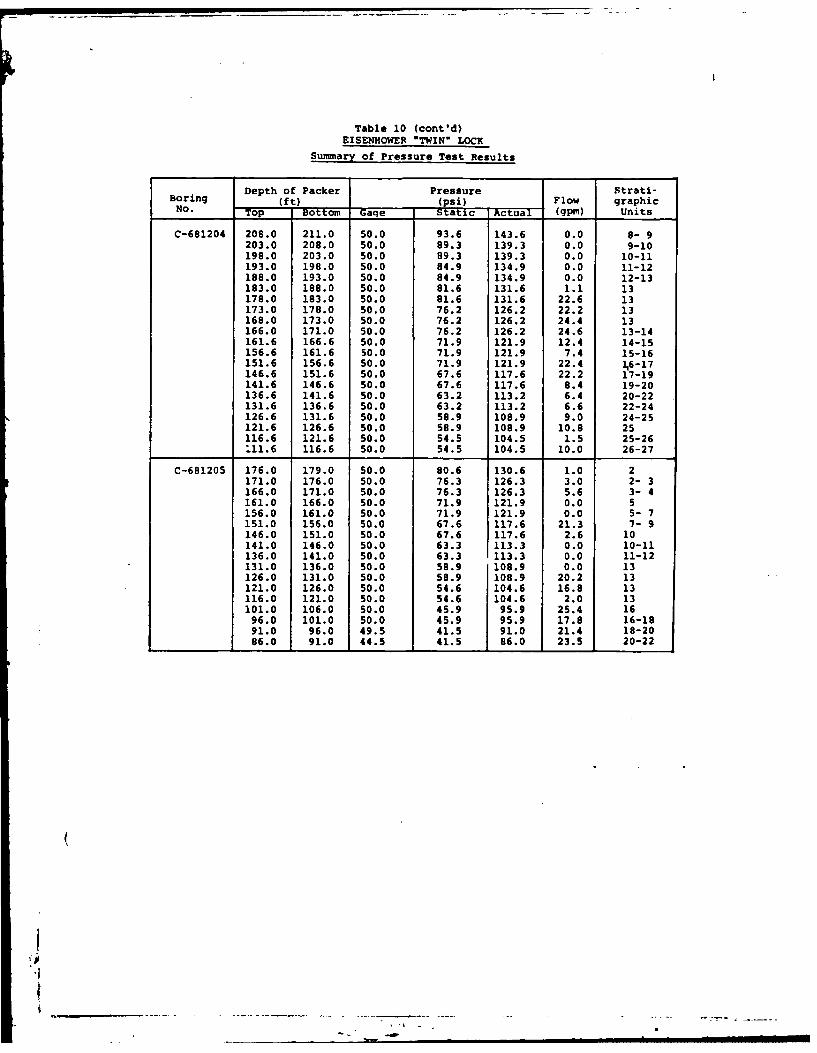
Pressure testing in bedrock was performed in 10 of the 12
borings; procedures and results are discussed in Section
5.3.1.
Upon completion of all drilling and testing, the holes
were backfilled with a neat cement grout to the top of rock and
from there to the ground surface with sand or a sand/bentonite
mixture.
4.1.2.2 Snell "Twin" - 1970
Of the 11 borings drilled in this program, 10 lie within
the lock area of the proposed "Twin" and one (C-701309) is
located on the north side of the present Snell Lock (see Plate
4). These holes with their locations and other pertinent data
are listed in Table 3, and the detailed geologic logs are
attached to this report. Plate 8 shows a geologic profile
through three of these borings.
The drilling was done from May 12 to July 23, 1970. All
holes were drilled vertically, and the drill rig, samplers and 7other equipment used were the same as described in Section
4.1.2.1. Figures 8 and 9 show photographs of typical rock
cores recovered during the drilling.
-52-
Eighteen undisturbed samples of the marine clay were taken
from borings UC-701306 (16 tubes) and UD-701308A (2 tubes)
using a 3-inch Shelby tube sampler.
The depth of overburden in the proposed "Twin" lock area
ranged from 42.9 feet to 76 feet, for an average of about 60
feet. Boring C-701309, located on the north side of the lock,
had 91.1 feet of overburden. Ten of the borings were continued
into the bedrock a maximum of 102 feet, and rock core recovery
averaged over 97%.
Borehole photographs were taken in orings C-701303 and
C-701306, and the logs are attached to this report.
Pressure testing in bedrock was performed in 10 borings;
procedures and results are discussed in Section 5.3.2.
As at the Eisenhower site, backfilling of holes was done
with a neat cement grout in bedrock, and sand, or a sand/bento-
nite mixture, n the overburden.
4.2 Geoph-. al Surveys
Two separate geophysical surveys have been carried out in
connection with studies for the St. Lawrence Seaway Project.
The first survey, conducted prior to construction in 1940-41,
covered the entire length of the project from Chimney Island
(northeast of Ogdensburg) to Cornwall Island, near the mouth of
the Raquette River. The seismic refraction method was used,
both on land and in the river. The latest survey was conducted
(in 1970 and was limited to the general area proposed for the
"Twin* lock sites south of Snell and Eisenhower Locks. Seismic
-53-
refraction and electrical resistivity were employed in this
investigation.
4.2.1 Seismic Exploration, 1940-41
The seismic investigations were conducted by the St.
Lawrence River District of the U.S. Army Corps of Engineers for
the general purpose of obtaining data between drill holes to
minimize the amount of drilling needed. The work was performed
between November 1940 and October 1941, with a 2 month suspen-
sion in March and April due to frost conditions. An array of
detectors (usually three) was placed on the ground surface and
charges of dynamite were exploded at various distances from the
detectors. An effort was made to conduct the survey on the
same type of overburden. For work on the river, special
waterproof equipment was designed. In quiet water the detec-
tors and charges were set using floats; in swift water special
procedures had to be worked out (Ref. 11).
From the time-distance graphs obtained by plotting the
seismic data, depths to bedrock were computed and top of rock
contour maps were drawn. In general, the correlation between
seismic information and drilling data was found to be quite
satisfactory, except for one area along the proposed alignment
for the Point Rockway Canal where comparatively low velocity
(5000 feet per second) material originally thought to be clay
or till was discovered to be shallow and fractured rock.
Another area, near the Massena Power Canal, showed erratic
readings and made precise interpretation difficult. This was
the result of artificial conditions created in the area by the
dumping of spoil from the excavation of the power canal.
-54-
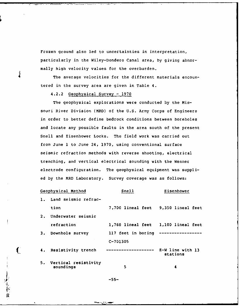
Frozen ground also led to uncertainties in interpretation,
particularly in the Wiley-Dondero Canal area, by giving abnor-
mally high velocity values for the overburden.
The average velocities for the different materials encoun-
tered in the survey area are given in Table 4.
4.2.2 Geophysical Survey - 1970
The geophysical explorations were conducted by the Mis-
souri River Division (MRD) of the U.S. Army Corps of Engineers
in order to better define bedrock conditions between boreholes
and locate any possible faults in the area south of the present
Snell and Eisenhower Locks. The field work was carried out
from June 1 to June 24, 1970, using conventional surface
seismic refraction methods with reverse shooting, electrical
trenching, and vertical electrical sounding with the Wenner
electrode configuration. The geophysical equipment was suppli-
ed by the MRD Laboratory. Survey coverage was as follows:
Geophysical Method Snell Eisenhower
1. Land seismic refrac-
tion 7,700 lineal feet 9,350 lineal feet
2. Underwater seismic
refraction 1,760 lineal feet 1,100 lineal feet
3. Downhole survey 117 feet in boring
C-701305
( 4. Resistivity trench ------------------- E-W line with 13stations
5. Vertical resistivitysoundings 5 4
4 -55-
Seismic lines were run both on land and in water; resisti-
vity stations were only on land. All shot points and stations
were surveyed by a crew from the Buffalo District, and
lithologic control was provided by a number of drill hole logs
at both sites.
The average seismic velocities and electrical resistivity
values for the various materials encountered are shown in Table
5. Based on these data, depths to bedrock were computed and
top of rock contour maps were produced for each site (Figures 3
and 5). In addition, a till isopach map was prepared for the
Eisenhower site (Figure 4).
The survey results indicated that little if any till would
be encountered during excavation at the Snell site, whereas a
considerable thickness (50 to 110 feet) could be found at the
Eisenhower site. The velocity of the till at both sites
indicated that it would be marginally rippable.
The survey also showed that the configuration of the
bedrock surface at the Eisenhower site was generally flat along
the west side but had broad N-S trending valleys and ridges to
the east. A buried ridge with an abrupt slope was found
trending about N200 E through the area near the eastern end.
At the Snell site, a bedrock high (about El 150 feet and
sloping west, north and east) was found at the SW corner of the
area. The bedrock surface is cut by two NE trending channels
nearly in the center of the areas.
No definite evidence of faulting was found.
-56-
5. FIELD AND LABORATORY TESTING
In the various drilling programs performed since 1895,
extensive sampling and testing of the overburden and bedrock
materials were done in the general vicinity of three of the
four alternative sites. No data is currently available for the
area of the High-Lift alternative.
5.1 Soil Testing
For the period prior to 1968, detailed soil data is
available from the 1941 and 1954-55 exploration programs.
Along the alignment for the 1941 proposed Point Rockway 'anal,
soil samples were taken with a 2-inch diameter "dry sampling
tube" and, for undisturbed samples of clay, a specially con-
structed spoon which provided samples 4-5/8 inches in dia-
meter. The clays were tested for moisture content, liquid
limit, plastic limit, specific gravity, consolidation and quick
shear. For a description of sampling and testing procedures,
see Ref. 12.
During the 1941 drilling program in the vicinity of
Eisenhower Lock, the overburden was sampled using 2-inch
split-spoon samplers and NX-size double tube core barrels.
The recovered samples were used .r classification, moisture
content determinations and mechanical analysis tests. In the
1954-55 program, soil samples were recovered by: (1) drive
sampling with 2-inch split spoon samplers with brass liners,
(2) washing, and (3) coring with NX and 6-inch double tube
core barrels. Testing included a full range of identification
tests (grain size, Atterberg limits, etc.) as well as triaxial
-57-
compression tests. See Ref. 13 for detailed sampling proce-
dures and test results.
During the 1941 program at Snell Lock, 1-1/2 inch and
2-inch split-spoon samplers were used to obtain soil samples
for classification, moisture content determinations and mecha-
nical analysis tests. The M.I.T. sampler was used to obtain
undisturbed samples of clay material for consolidation and
shear tests. In the 1954-55 program, 2-inch split-spoon
samplers with brass liners were used to recover material for
classification tests and moisture determinations. Undisturbed
samples for strength tests were obtained with 5-inch Shelby
tube samplers. Laboratory testing of the undisturbed samples
included determination of moisture content, liquid limits,
plastic limits, and density, and triaxial compression tests.
The bottom portion of seven (7) of the soils borings was cored
with a 6-inch core barrel. The core samples were used for
classification and moisture determinations, and some cores were
placed in sheet metal tubes for future reference. See Ref. 14
for detailed sampling procedures and test results.
5.1.1 Eisenhower "Twin" - 1968
As mentioned in Section 4.1.2.1, during the 1968 program,
soil sampling was performed with a 2-inch split-spoon sampler,
3-inch Shelby tube, 4-inch Denison sampler and several double
tube core barrels with 2-3/4" x 3-7/8", 4" x 5", and 6" x
7-3/4" size drill bits. Laboratory testing was done by the
North Central Division, U.S. Corps of Engineers, Chicago,
Illinois.
-58-
In boring UDC-681201, fourteen (14) Shelby tube samples
were recovered in the marine clay. The tests performed on this
material and the test results are shown in Table 6. The range
in values of several important characteristics are:
Liquid Limit (%) 33 to 64
Plastic Limit (%) 17 to 27
Dry density (pcf) 58.3 to 87.2
Water content (%) 34.6 to 70.0
Nine (9) Shelby tube samples of the marine clay were taken
fiom boring UDC-681202 (see Plate 13). Table 6 summarizes the
test results and shows the following ranges:
Liquid Limit (%) 45 to 57
Plastic Limit (%) 19 to 25
Dry density (pcf) 61.7 to 76.7
Water content (%) 44.8 to 64.8
In boring C-681206, the backfill along the south side of
Eisenhower Lock was sampled using 4" x 5" double tube core
barrel. Table 6 shows the test results. Thirty-one (31) of
the samples were grouped into eight (8) test series in order to
obtain strength envelopes from the triaxial test results. The
material is basically silty sand and gravel and shows the
following range of values:
Fines content (%) 23 to 44
Liquid Limit (%) 13 to 21
Plastic Limit (%) 10 to 14
Dry density (pcf) 129.9 to 153.3
Water content (%) 2.9 to 9.3
-59-
5.1.2 Snell "Twin" - 1970
The procedures and equipment used to sample the overburden
are the same as described in Section 4.1.2.1. Laboratory
testing was done by the North Central Division, U.S. Corps of
Engineers, Chicago, Illinois. The tests performed and their
results are shown in Table 7.
In boring UC-701306, sixteen (16) 3-inch diameter Shelby
tube samples were recovered in the marine clay. The test
results showed the following range of values:
Liquid Limit (%) 40 to 59
Plastic Limit (%) 19 to 26
Dry density (pcf) 61.9 to 78.5
Water content (%) 43.4 to 64.9
Two (2) Shelby tube samples of the marine clay were taken
from boring UD-701308A, and the test results showed:
Liquid Limit (%) 58 to 60
Plastic Limit (%) 22 to 23
Dry density (pcf) 74.3 to 89.3
Water content (%) 32.4 to 47.3
5.2 Rock Testing
During the 1941 drilling program for the proposed Point
Rockway Canal, rock cores of the dolomite bedrock were obtained
and tested to determine whether the rock from the canal excava-
tion was suitable for concrete aggregate.
Rock cores were also taken in the vicinity of the Eisen-
hower and Snell Locks in the various drilling programs perform-
ed prior to 1968 in these areas. The rock was described and
classified, but no record of any type of testing is available.
-60-
5.2.1 Eisenhower "Twin" - 1968
Rock cores during the 1968 program were obtained with an
NX-size double tube core barrel. Selected samples from borings
C-681210 and C-681211 were sent to the Ohio River Division
Laboratories (ORDL) for testing. The strength tests performed
included compressive strength, direct shear, sliding friction,
bond shear and triaxial compression. In addition, moisture
contents and unit weights were determined and petrographic
analyses were made on twelve (12) samples. Table 8 shows a
summary of the test results. The water content measurements
were quite low (less than 1% in most cases) and it was ques-
tionable whether they were truly representative of in situ
conditions. Unit weight values ranged from a high of 175.3 pcf
for dolomite to 132 pcf for a sample of gypsum. Sample 1A from
boring C-681211 was tested to determine Poisson's Ratio, and
the recommended average value was found to be 0.075. See Ref.16
for a detailed description of testing procedures and results.
5.2.2 Snell "Twin"-1970
During the 1970 drilling program, rock cores were obtained
with an NX-size double tube core barrel. Selected samples from
borings C-701302, C-701303 and UC-701306 were sent to ORDL for
testing. Strength tests included unconfined compression,
direct shear, bond shear, sliding friction (rock on rock) and
triaxial compression. Moisture contents, specific gravity and
unit weights were also determined, and petrographic analyses
were made on twelve (12) samples. Table 9 shows a summary of
-61-
the test results. The results of the direct shear tests were
considered somewhat questionable because the strength of the
samples sometimes exceeded the crushing strength of the hydro-
stone. Water contents were very low - less than 1% in most
cases. Unit weights were very similar for all samples tested,
ranging from a high of 178.2 pcf for a sample of highly argil-
laceous dolomite to 173.4 pcf for a typical dolomite. Poisson's
Ratio was determined on samples 4 and 6 from boring C-701303,
and the recommended average values were 0.16 and 0.26, respec-
tively. See Ref. 17 for a detailed description of testing
procedures and results.
5.3 Pressure Testing
There are no records to indicate that water pressure
testing of the bedrock was done during the 1941 drilling
program along the alignment of the proposed Point Rockway
Canal.
In the 1954-55 drilling program at Eisenhower Lock,
fifteen (15) of the borings in bedrock were pressure-tested
with water using a 5-foot double packer to determine permeabi-
lity or leakage conditions in the bedrock. During construction
in 1956, seventeen (17) additional foundation exploration holes
were pressure-tested, again using 5-foot double packers.
Because most of the 1956 borings showed flowing water under
artesian pressure, flow measurements were substituted for
pressure tests in other holes. In total, flow measurements )were made on fifteen (15) holes including eight (8) of the
holes that were pressure-tested. See Ref. 13 for a detailed
description of test procedures and results.
-62-
In the 1954-55 drilling program at Snell Lock, nineteen
(19) of the exploratory holes in bedrock were pressure-tested
with water using a 5-foot double packer. Additionally, a
pumping test was performed on hole GR-16, with four other holes
serving as observation wells. Permeability tests were perform-
ed in five (5) borings. During construction in 1956, pressure
tests were performed in seven (7) of the foundation exploration
holes. A single packer was used to test a section extending
from 20 feet below top of bedrock to the bottom of the hole.
See Ref. 14 for a detailed description of test procedures and
results.
5.3.1 Eisenhower "Twin" - 1968
Pressure testing in bedrock was performed in ten (10) of
the twelve (12) borings drilled in 1968. Both a single packer
and a 5-foot double packer set-up were used. The maximum gage
pressure was limited to 50 psi and was adjusted accordingly so
that the pressure in the zone being tested would not exceed one
(1) psi per foot of overlying material. The test results are
listed in Table 10.
Of the 151 tests performed, 96 showed water losses greater
than 10 gpm. Over 50% of the high loss zones occurred within
stratigraphic Units 13 to 16. Sections of Unit 13 were includ-
ed in nearly 30% of these zones, however, it should be noted
that Unit 13 is by far the thickest unit (24.4 feet thick) in
the area and it was involved in many more pressure tests than
any other single unit.
Fifty (50) tests showed water losses greater than 20 gpm.
-63-
Units 13 to 16 accounted for nearly two-thirds of the high loss
zones, with Unit 13 included in over 40% of them.
The maximum water loss of 32 gpm occurred when testing the
bottom 19 feet of boring UDC-681201. For a 5-foot zone, the
maximum was 27 gpm within Units 13 to 16 in boring UDC-681202.
Forty (40) tests showed no water loss.
5.3.2 Snell "Twin" - 1970
In the 1970 drilling programs, ten (10) of the eleven (11)
borings were pressure-tested in bedrock. The same equipment
and test procedures were used as described in Section 5.3.1.
The test results are listed in Table 11.
In the 161 tests performed, 63 showed water losses greater
than 10 gpm. Units 13 to 16 accounted for more than 60% of the
high loss zones, with Unit 13 included in over 20% of them.
The maximum water loss recorded was 19.5 gpm for a 5-foot
zone between Units 25 and 26 in boring C-701303. Sixty (60)
tests showed no water loss.
6. GEOTECHNICAL ASPECTS
The geotechnical aspects for the design of the four
proposed alternative sites can not be discussed in detail since
no extensive site specific information is available. There is,
however, extensive information regarding subsurface conditions
at the sites of the existing Snell, Eisenhower and Iroquois
Locks. The proposed sites for the Snell and Eisenhower "Twin"
Locks are in close proximity to the existing locks and the
locations of several previously drilled borings are within the
proposed alternative alignments and therefore can be used in
making a reasonable assessment of subsurface conditions. In
-64-
the vicinity of Snell Lock, about 15 borings exist along the
alignment of the proposed "Twin" and about 25 borings for the
Eisenhower site. Practically no useful boring information is
available for the High-Lift alternative; there is some geophy-
sical data and local water well information, and this has been
used in determining subsurface conditions. At the Iroquois
site, about 15 previously drilled borings can be located within
the proposed alternative alignment and almost all of these are
located at the upstream end. In addition, the information
obtained from these borings is very sketchy and very little
detail is given regarding the materials. Nevertheless, based
on this limited information and experiences others have had in
previously constructed projects in the vicinity, certain
general inferences can be made regarding the alternative
sites.
During the construction of Snell, Eisenhower and Iroquois
Locks, difficulties were encountered which were directly
attributable to the foundation materials. A general descrip-
tion of the subsurface conditions at the four alternative sites
has been given in previous paragraphs. It can be seen that
there are basically three materials, two of which caused most
of the difficulties during the construction, namely; the marine
clays and the glacial tills. Dolomite, the underlying bedrock,
created few problems. Burke (Ref.3), Armstrong and Burnett
(Ref. 1) and Haines and Olson (Ref. 6) describe in detail the
design and construction problems encountered during construc-
tion of the St. Lawrence Seaway.
-65-
The difficulties caused by the marine clays were a result
of their weak strength and extreme sensitivity. The design
and construction of the canal slopes of major cuts necessitated
extensive investigation and testing programs. Resulting cut
slopes varied from 1V to 2H in areas where depth of cuts or
thickness of clay was shallow to 1V to 10H where relatively
deep cuts were required. In areas where dikes were constructed
over the clay, they had to be wide and flat sloped for stabi-
lity purposes. The disposal of the extremely sensitive clays
also created a problem. When reworked, the clays became "soup"
and it was necessary, therefore, to provide extensive spoil
areas to allow the clay to be deposited to shallow depths and
very flat slopes. For the same reason, it was very difficult
to have construction traffic on the clays.
The problems associated with the glacial tills were
basically those of excavation, seepage and trafficability. A
detailed description of the difficulties during design and
construction is given by the previously mentioned authors and
by Cleaves (Ref.4). Excavation problems were caused by the
compact to highly compact nature of the basal till (Malone)
which also contained boulders. In wintertime, it was necessary
to blast the till which became frozen. The presence of sand
and silty zones within the tills further increased the diffi-
culties because these materials became "quick", bogging down
excavation equipment and causing excessive seepage and stabi-
lity problems in cuts. In addition, the upper tills, which are
less compact, became impassable during seasons of thaw and high
-66-
rainfall. It is apparent, therefore, that prior to final
design, the location and extent of the clays and tills needs to
be defined and a final assessment be made as to the viability
of the sites. At that time the exact alignment and location
should be made for the proposed channels, guide walls and
locks. The determination of design parameters will be required
also for utiliation in stability and seepage analysis and in
evaluating temporary support systems and trafficability.
Since the proposed sites are within Seismic Zone No. 3,
dynamic analyses will be needed for the design of proposed
structures and cut slopes. Dynamic parameters for the rock and
soil types will have to be established and an examination and
analysis of seismic data will be required for the selection of
a Maximum Credible Earthquake, a Design Earthquake and a Design
Accelerogram.
To obtain the aforementioned information, an extensive
subsurface exploration and testing program should be carried
out at the four sites. These programs should include: the
drilling of vertical and inclined holes; obtaining disturbed
and undisturbed samples of overburden; core retrieval in rock;
seepage testing in overburden and water pressure testing in
rock; digging of test pits and trenches, geophysical surveys
including shear wave measurements (i.e., cross-hole methods);
and laboratory testing of rock and soil samples. It also will
(be necessary to search for possible sources of construction
materials especially fine and coarse aggregate. These probably
can be found in the sand and gravel deposits in the tills.
-67-
............. IN
Consideration should be given to the installation of a seismo-
logical network for the monitoring of macro- and/or micro-seis-
mic activity and instrumentation for monitoring ground water.
Laboratory testing should include classification and
engineering properties tests such as: compaction, permeability,
consolidation, direct shear and triaxial compression. Dynamic
testing should include simple cyclic shear, cyclic triaxial
compression and resonant column.
7. CONCLUSIONS
A review and assessment of the information presented above
indicates that construction of the alternative locks and
channels at the proposed locations appears to be geotechnically
feasible. It is apparent that whichever is the selected
location, substantial additional geologic, geophysical and
geotechnical investigations will be required prior to the final
design. These investigations should include extensive site
specific subsurface exploration, field and laboratory testing
of soil and rock samples, geophysical surveys, hydrogeologic
studies and seismological (dynamic) investigations.
Based on the subsurface conditions determined from avail-
able data, it is reasonable to assume that similar bedrock
conditions will be revealed by future investigations. Since
the surficial deposits are basically glacial in nature, it can
be expected that erratic soil conditions will exist throughout
the area. However, the major soil types will probably be
similar to those which have been encountered in the past.
A major advantage in the future design and construction of
project structures will be the experiences gained during the
-68-
....
original construction of the Seaway. Knowing in advance in
which materials problems can be expected (i.e., the very soft
marine clays and the extremely dense glacial tills), and to
I have design and construction solutions to these problems is a
great advantage for any project.
(
-69-
- - - , - w I eOI II - -
REFERENCES
1. ARMSTRONG, Ellis L., and BURNETT, Richard E., (1957),Earth Excavation and Related Soil Problems on St.
Lawrence Power and Seaway Projects - International RapidsSection, Symposium, ASCE, Buffalo, New York.
2. BERKEY, C.P., (1945), A Geological Study of the Massena-
Cornwall Earthquake on September 5, 1944 and Its Bearingon the Proposed St. Lawrence River Project, U.S. EngineerOffice, New York District, unpublished report.
3. BURKE, Harris H., (1957), Soils and Foundations Problemson the Long Sault Canal, Saint Lawrence Seaway - Interna-
tional Rapids Section, Symposium, ASCE, Buffalo, New York.
4. CLEAVES, Arthur B., (1964), Engineering Geology Character-istics of Basal Till in Engineering Geology Case Histories
Numbers 1-5, Parker Trask and George A. Kiersch, editors,Geol. Soc. of Amer., New York, pp. 235-241.
5. COFFMAN, Jerry L., and VON HAKE, Carl A., (1973), editors,Earthquake History of the United States, U.S. Dept. ofCommerce, N.O.A.A., E.D.S., Washington, D.C., Pub. 41-1(Rev. Ed. through 1970), 208 p.
6. HAINES, Reuben M., and OLSON, George E., (1957), Soilsand Earthwork Features of St. Lawrence River Power andSeaway Projects - International Rapids Section,Symposium, ASCE, Buffalo, New York.
7. MacCLINTOCK, Paul, (1958), Glacial Geology of the St.Lawrence Seaway and Power Projects, N.Y. State Museumand Science Service, Albany, N.Y., 26 p.
8. MacCLINTOCK, Paul, and STEWART, D.P., (1965), Pleistocene
Geology of the St. Lawrence Lowland, Bull. No. 394,N.Y. State Museum and Science Service, Albany, N.Y.
9. TRAINER, F.W., and SALVAS, E.H., (1962), Ground-WaterResources of the Massena-Waddington Area, St. LawrenceCounty, New York, Bull. GW-47, N.Y. State Water ResourcesCommission, Albany, N.Y.
10. U.S. ARMY, (1942), St. Lawrence River Project, FinalReport, Appendix B-l, Folio of Subsurface Exploration,Corps of Engineers, Buffalo District, unpublished report.
11. U.S. ARMY, (1942), St. Lawrence River Project, FinalReport, Appendix B-2, Seismic Exploration 1940 and 1941,Corps of Engineers, Buffalo District, unpublished report.
-70-
12. U.S. ARMY, (1942), St. Lawrence River Project, FinalReport, Appendix Iii-B (3), Point Rockway Lock, Analysisof Design, Corps of Engineers, Buffalo District, unpub-lished report.
13. U.S. ARMY, (1958a), Foundation Report, Dwight D. Eisen-hower Lock, Corps of Engineers, Buffalo District, unpub-
lished report.
14. U.S. ARMY, (1958b), Foundation Report, Bertrand H. SnellLock, Corps of Engineers, Buffalo District, unpublishedreport.
15. U.S. ARMY, (1970), St. Lawrence Seaway, Study of Addi-tional Locks, Geophysical Explorations, Corps of Engineers,Missouri River Division, unpublished report.
16. U.S. ARMY, (1970), St. Lawrence Seaway Twinning Study,Eisenhower Lock, NX Rock Core Testing, Corps of Engi-neers, Ohio River Division, unpublished report.
17. U.S. ARMY, (1971), St. Lawrence Seaway Twinning Study,Snell Lock, NX Rock Core Testing, Corps of Engineers, OhioRiver Division, unpublished report.
18. YANG, Jih-Ping, and AGGARWAL, Yash Pal, (in press),Seismotectonics of Northeastern United States and AdjacentCanada, Lamont-Doherty Geological Observatory of ColumbiaUniversity, Palisades, New York.
-71-
Table 1Stratigraphic Units in Bedrock
E-44 ~ f(n 0 H- H
Z DESCRIPTION
0 MARINE CLAY Borderline Clay (CL-CH) Generallyto classified as Fat Clay (CH) with a silty texture; soft75 to very soft; moist to wet; dark gray to bluish-gray.
FORT COVINGTON (Glacial Till) Lean Clay to Sandy Clay(CL-SC) : Contains gravel, cobbles and boulders embed-ded in clay; generally very stiff to hard; dry to
0 slightly damp; gray to brownish-gray.E to
110 MALONE (Glacial Till) Lean Clay to Sandy Clay (CL-SC)Contains gravel, cobbles and boulders embedded in clay;generally very stiff to hard; dry to slightly damp;gray to brownish-gray.
DOLOMITE: Thick-bedded to massive; occasionally argil-laceous, occasional shale partings and bands; moderate-ly hard; very finely crystalline to dense. Containsan Intraformational Conglomerate zone from 0.1 to 1.0-
27 10.4 foot thick at or near the base and another 0.2 to 0.9-foot thick from 1.8 to 3.2 feet above the base. TheIntraformational Conglomerate consists of small graydolomite fragments in a lighter gray dolomite matrix.Gray to dark gray.
DOLOMITE: Thin to medium-bedded; shaly and argilla-ceous at top and bottom with a basal sandy textured
C.) 4.26 to shale, numerous calcite veinlets in darker gray dolo-6.4 mite at top and bottom; moderately hard to hard; finely6 crystalline to dense; dark gray at top and bottom,
obluish-gray in middle.
DOLOMITE: Thin to medium-bedded; numerous stylolitic
8.9 shale and calcite partings, shale and dolomitic shale
25 to partings, bands and beds with shale band at base; mod-
10.2 erately hard to hard; very finely crystalline to dense;Intraformational Conglomerate at base. Unit is pittedand vuggy; medium bluish-gray.
DOLOMITE: Thin-bedded top and bottom, massive in mid-
5.1 DOLOMITE: Thick-bedded to massive; argillaceous,
2 2 toseveral shaly bands throughout; moderately hard; dense;5.6 light gray at top, bluish-gray middle and brownish-grayat base.
SHALE and DOLOMITE: Thin-bedded; shale is dolomitic
and dolomite is argillaceous, interbedded; slightlysandy texture at base; moderately hard; dense; darkgray.
DOLOMITE: Thin to thick-bedded; moderately hard;dense; bluish-gray upper, medium gray in lower. Shale0.1 to 0.3-foot at base, and 0.3-foot thick approxi-
3. t mately 0.7-foot below top. May or may not contain 220 to
4.1 zones of Intraformational Conglomerate; one directlyabove the upper shale (0.2-foot thick) and one 1.5 feetbelow top of unit (0.7-foot thick) (Not present in all
DOLOMITE: Thin-bedded; argillaceous, several styloli-2.4 tic shale partings, basal shale is (0.3-foot thick)
to9 platy to laminated, slightly carbonaceous; moderatelyWhard; black. Dolomite contains numerous high angleW 3.0
veinlets of calcite throughout; moderately hard; dense;occasional vugs filled with calcite with some solution-
ed out; dark gray to black.
DOLOMITE: Thin to thick-bedded; slightly argillaceous
2.0 Basal platy black shale (0.1 to 0.3-foot thick) and18 t bands of shale interbedded with dolomite approximately3.6 0.8-foot and 1.4 feet from base; stylolitic shale part-
ings in upper 0.3-foot; moderately hard; very finely
crystalline to dense; occasional pits and vugs in up-per 0.7-foot; bluish-gray.
1.1 DOLOMITE: Thin to medium-bedded; very argillaceous,17 to shaly appearance with several black shale partings and
2.1 bands; moderately hard; dense; very dark gray.
DOLOMITE: Medium to thick-bedded; slightly argilla-
ceous, shale bands and beds throughout; gypsum bands,
beds and masses with occasional partings in lower16 8.5 part; moderately hard; very finely crystalline to
dense; occasional pits and vugs where gypsum has
been removed; bluish-gray to brownish-gray.
Table 1 (cont'd)Stratigraphic Units in Bedrock
Z DESCRIPTION
GYPSUM: Thin to medium-bedded; laminated and inter-1.4 bedded satinspar and gypsum in upper part, irregular
15 to laminated gypsum in lower part; soft to moderately3.8 hard; dense to crystalline; mottled various shades of
light and dark gray.
DOLOMITE: Thin-bedded; argillaceous with gypsum part-1.9 ings and irregular partings at base; a 0.1 to 0.3-foot
14 to thick dolomitic shale with partings mark top of unit;3.8 moderately hard to hard; dense; medium gray to gray.
DOLOMITE: Thin to medium-bedded; numerous bands andbeds of darker gray shaly to argillaceous dolomite;dark gray to black shale bands approximately 2.4 feet
13 24.4 below top, and a black platy carbonaceous shale approx-imately 2.0 feet above base of unit; moderately hard;dense; pitted and vuggy near basal foot; brownish-gray
to bluish-gray.
DOLOMITE: Thin to medium-bedded; shale partings andstylolitic shale partings throughout. Black platy
2.1 dolomitic shale (0.2-foot thick) at top, and a basal12 to sandy dolomite (0.04-foot thick). Base of unit is
2.7 marked by a black fissile shale with gypsum partings.Moderately hard; dense; brown to brownish-gray.
DOLOMITE: Medium-bedded upper, thick-bedded lower;shale bands in upper 1.1 to 1.5 feet with stylolitic
7.1 shale partings and bands in upper part, gypsum masses11 to in middle, lower part is nearly a mass of laminated
0.7 gypsum (3.0 feet); moderately hard; (gypsum is soft tomoderately hard) dense; medium gray.
DOLOMITE: Thin to thick-bedded; argillaceous with5.6 shale and gypsum partings and occasional gypsum nod-
10 to ules; moderately hard; dense; medium gray upper, light5.9 gray middle and brownish-gray lower.
DOLOMITE: Thin-bedded; gypsum partings and shale9 2.9 bands, shale band approximately 0.6-foot below top
6 to shale at top; moderately hard; very finely crystalline2.6 to dense; lower part highly fractured - fractures
filled with gypsum; light gray to light bluish-gray.
GYPSUM and DOLOMITE: Gypsum in upper 0.6 to 0.9-foot(0.4-foot thick), fractured gypsum and shaly dolomite
5 6.3 at base; laminated to thin-bedded; gypsum partingsthroughout; moderately hard; dense; white at top,medium dark gray lower part.
DOLOMITE: Thin to thick-bedded; argillaceous in top3.1 1.0-foot with sandy textured dolomitic shale band at
4 to top (gray to dark gray), several dolomitic shale part-5.0 ings and bands throughout; dense; moderately hard;
medium to dark gray.
SHALE and DOLOMITE: Laminated to thin-bedded; shaleinterlaminated with gypsum in upper 1.0 to 1.5 feet.
2.5 Dolomite in middle 0.7-foot and shaly dolomite in basal3 to 0.8-foot. Dolomite and shaly dolomite are dense; shal
3.6 is soft; dolomite and shaly dolomite are moderately
hard; light gray to black.
DOLOMITE-LIMESTONE: Thin to thick-bedded; shale andstylolitic shale partings throughout, particularlynear basal contact, secondary gypsum approximately 1.6feet and 3.0 feet from top, occasional gypsum partings;moderately hard; very finely crystalline to dense;medium to light gray.
DOLOMITE: Thin to thick-bedded; argillaceous, numerous
1 9.3 shale and argillaceous dolomite partings and bandsthroughout, gypsum partings and fracture filling com-mon; moderately hard; dense; bluish-gray.
0 1.2 SHALE: Laminated; dolomitic; moderately hard; darkgray to black.
Notes for Table 1
The description of the soils and bedrock on Table 1 is based on the follow-ing criteria:
SOILS
1. Classification - all soils are classified using the Unified Soil Clas-sification System.
2. Consistency - For drive sample borings the following was used todetermine relative density or consistency. Consistency for gravels is notused.
Basic : Density or : Range of Standard (i)Soil Type : Consistency : Penetration Resistance
Cohesionless : Very loose less than 4 per foot: Loose 4 to 10: Medium dense : 10 to 30: Dense : 30 to 50: Very dense : Greater than 50
Cohesive : Very soft : Less than 2 per foot:Soft 2 to 4* Medium stiff : 4 to 8
:Stiff :8 to 15* Very stiff : 15 to 30: Hard : Greater than 30
(1) Number of blows from 140-lb. weight falling 30 inches to drive 2-inchOD, 1-3/8-inch ID, sampler
For undisturbed sample borings a pocket pentrometer or torvane was usedto determine consistency and the following was used as a guide:
Unconfined Compressive
Strength (Tons/Sq Ft) Consistency
Less than .25 Very soft.25 - .5 Soft
.5 - 1.0 Medium
1.0 - 2.0 Stiff2.0 - 4.0 Very stiff
Greater than 4.0 Hard
3. Moisture Content - Moisture content of soil has been described in thefollowing terms:
Dry. No discernible moisture present.
Damp. Enough moisture present to darken the appearance but no moistureon material adheres to the hand.
Moist. Will moisten the hand.
Wet. Visible water present; plastic materials will leave sticky residue
in hand when remolded.
Saturated. 100 percent of all the void space is filled with water.
4. Color - Color was described at the time of drilling.
BEDROCK
1. Bedrock classification was based on the rock types described in thefoundation reports for the two existing locks. The rock units described inthis report are based on the descriptions shown in the foundation reports(see references 13 and 14). In addition to those descriptions the followingcriteria was used to describe the bedrock. All descriptions are based on avisual examination at the time of drilling.
2. Bedding - Has been described as massive, thin to medium bedded, fissile,cross-bedded, foliated, platy, fragmental, etc., as indicated below:
(a) Parting less than 0.02 foot(b) Band 0.02 foot to 0.2 foot(c) Thin Bed 0.2 foot to 0.5 foot(d) Medium Bed 0.5 foot to 1.0 foot(e) Thick Bed 1.0 foot to 2.0 feet(f) Massive Over 2.0 feet
Parting and Band refer to single stratum& The term "massive" may beapplied to describe a single bed.
very soft or plastic - can be indented easily with thumbsoft - can be scratched with fingernailmoderately hard - can be scratched easily with knife; cannot be
scratched with fingernailhard - difficult to scratch with knifevery hard - cannot be scratched with knife
5. Crystallinity or texture.
dense - crystals are so small that they cannot be distinguished with thenaked eye.
very finely crystalline - crystals barely discernible with the naked eye.finely crystalline - crystals are small but easily discernible with naked
eye.crystalline - crystals are medium size - up to 1/8 inch in diameter.very coarsely crystalline - crystals larger than 1/4 inch in diameter.
i. Pit - Vug - Cavity - In order to more closely define voids found in bedrock, the following terms have been used:
Porous. Smaller than pinhead. Usually not discernible to the naked eye.Their presence is indicated by the degree of absorbency of the core.
Pitted. Pinhead size to 1/4-inch. If they are numerous enough thatonly thin walls separate the individual pits, the core may be described as
honeycombed.
Vug. 1/4-inch to the diameter of the core. The upper limit will varywith the size of core.
Cavity. Larger than the diameter of the core.
7. Structure.
Bedding: flat, gently dipping, steeply dipping.
Fractures: scattered, closely spaced, open, cemented, or tight.
Brecciated (sheared & fragmented).
Joints.
Faulted.
Slickensides.
8. Degree of Weathering. Unweathered, slightly weather; badly weathered.
9. Solution and Void Conditions. Solid, contains no voids; vuggy (pitted);vesicular; porous; cavities; cavernous.
10. Swelling Properties. Nonswelling; swelling
11. Slaking Properties. Nonslaking; slakes slowly on exposure; slakesreadily on exposure.
12. Color of Unit.
444 .5*0 Ci C co % N v.4 I '. r4 cn N w w
0 m M Q 0 1 0 0 0 0 0
O 4
r.- o__ LA ___ ___ _a;_____ ___ _c;_____ _ q_
44
01.w0 %D4 .D 0D 4 (A v-I LA N L N 0
-4 0 LA .4 0C1
4-) N IM 0 N Nn (4 r e N 'm vI 0n 0n0 -4 -4 -4
0D to 04 40 ' 0 -4On-
.IJ1. 44 ~ U- N- m ~ 0" Nn v- A ' 0~00 q; 04 C4I I~ L ND N M m 4 f
CM w4 Z 0 4 - - 9- 4 v--4 I I r- 4 r- - '-
0)
v-4 r-4C v-I O-I m A L N 4 0 m- %0
40 0' 4 w-4 c; LA '0 4 O iI cNU). $4J 0V -4 -4 -4 -4 0- C 4 - 4 v-4 -4 v-
v- H _3__ N N N N N N q N N C
-4;
C:) No 00 0J 0 0 4-I 0 v-I e 0 4J w '0 4C i 0 D *9 0% *- . *oQ 0 - G . - m
4o g V- 0 M) n OD 0 0 0 t n 4 r L O 00 N f C.4 4 0 0D %Dr- LA C4 r 0 LA %oo% 0o r. r, a% inqI%
90 4J r- m 0 N N m N n N
4. go (d s Id . a6t o o t o4J 0 41 tP 4J U J 0 4 J ~ -0~ 4J 4J41q*.l4J 0 4 Oul .,. 4 W9U 4U 4t +n w En 4. 1 4n m + n 4 U)
0 -I NO 'L L 0 vIi~4I 'A OA WA M 0*e C4
4 N m ' -W LA n %'~ D '00 0- m0 LAD- r4 C4
CD Co N N N (' A N0 N- N' N N
U. L)
o o -4 0 (4 N 0 40 lw I %D'0% 0 0 0 0) 0 0 tA I IA V
41 i -4 -4 -4 r-4 r4I
rz4-I$4-4
WJ -4 LM 0 0 0 0 N- m r-4 0 ..-I %
U) - r- %0 IM IA V in r-I 0% q9
440
r (- (N (4 Io r- N0 IA r- Ln0 -44
41.
8a .0 4-4 0 Q % r- N N, IA -4 qw I 0 %aOl 0 0 * * * * *I
5-4 r. k N 0; 0% ; 4~ M -I I
en Qj9 1V 4 V fn 0n 04 ON CD a N (N 1 m% (-4. 0 4) -4 0-4 -4 t-
4 -4 r-I -4 I -
H ca
0 W
E--4 1-I4A IA 0 D N N 0
(N (N1 (N - 4 - - 4 - 4 -4$4i 0 0 0 ta IA IA 1.0 No ND
0 + + + + +- + + +- + .-I +..- 4~ IAIA o ni L LALAL t-I NIA t-I NO t-4i ot OA OLA + 0 -4 0
tor.-14 IA L +IA IA +IA tI+ IA + t + LA-+- IA+ qw+ Ln +00 4 IA m (N %0 (N V (N qr qv ' Nnv t
) a
(4 I 0 ' -' 4US to - t M - to -- toM 44.~ J t.4 4J ~4 01 4J0 1 0 p4 94J 4 4)0 r4
0 0 0 0 0 0 0 0 N 0 0-N fn en N C-r Nn en fn N-
'4 o. -D o o. o r- c - ,.-
Table 4
1940-41 Survey: Seismic Velocities of Materials
Average Seismic
Material Velocities (fps)
1. Very loose material 1000 - 2000
2. Relatively soft material(silt or clay) or loose till 4500 - 5000
3. Compact glacial till >5000
4. Bedrock 16,400
Table 5
1970 Survey: Seismic Velocities andElectrical Resistivities of Materials
Average Seismic Average ElectricalVelocities (fps) Resistivity (ohm-ft)
Material Snell Eisenhower Snell Eisenhower
1. Soil and backfill 1700-3300 1200-3800 220-4300 97-850
1. Concern has been expressed over the fact that the values for unit weightof rock specimens tested in direct shear, triaxial shear, and unconfinedcompression do not always equal the specific gravity of the specimen times62.4 pounds/cubic foot.
2. A search of the files was made and all of the of the work and data sheetswere examined. It was determined that all values were actual determinationsand that the discrepancies could be attributed to the following:
a. Both the specific gravity and the unit weight values were determinedunder saturated/surface-dry conditions.
b. Both determinations are very sensitive to small changes in watercontent. Heterogeneous rocks are especially sensitive to changes in watercontent below 25 percent.
c. The water content of rocks will decrease by 25 percent in 10 minuteswhen exposed to air at 60-65 percent relative humidity and 20-220 C. (Broch,E., "The Influence of Water on Some Rock Properties," Norwegian Institute ofTechnology, 1974).
d. The relation, Specific Gr~ity X 62.4 lbs./cu. ft. - unit weight,holds true only for homogeneous materials. Rock, in particularly this rock,is heterogeneous and, therefore, if a different specimen was used for each ofthe two tests, the value would differ by at least 4 or 5 lbs./cu. ft. Evenif the same specimen was used, the difference could be 1-2 lbs/cu. ft.
I
*..
Ta t ' ~
-
-
-.
I1 I I :
cuJ
0*
0,u. OC)O0 0IA
jo. to~~ pw af
0S 0
.0.a: ZI 4A
M~AS. ..9
-S
q
4it
Off ~- -
00
I 41
I II
0
0
S -,* A.Ji.&
0 ;ad4 -4
x X8
.0 a~t
4ga
ad&Ia gal
'-4v'
E0.
61 -
__ ALti
AD-A112 306 TZPPETTS-ASETT-CCATYHY-TRATTON NEW YORK F/6 13/2ST. LAWRENCE SEAWAY ADDITIONAL. LOCKS STUDY. SMOTECHNICAL REPOQT--ETC(U)
UNLSIIDMAR 81 T BOGAL OACW49-60-C-0002N
2 2 S
111 128 12.5
I'll' lla _
S13.2 fl
11111 1.251.4 1I.2
liIi l II 1=4 1.6
MICROCOPY RESOLUTION TEST CHARTNATIONAL BUREAU Of STANOAROS-1963-A
Table 10EISENHOWER "TWIN* LOCK
Summary of Pressure Test Results
Depth of Packer Pressure Strati-Boring (ft) _ _si ) Flow graphicNo. TOP Bottom Gaqe Static Actual (gP) Units
SA',AY, STUDY OF: ADDITIONAL LO~kS,GEOPHYiS.CAL SP-1EXPLORATIONS, CORPS OF ENGIN EERS, M !SSOURI
RIVER DIVISION, 1970,R-I
2) BEDROCK CONTOURS ARE IN FEET ABOVE 0IGLD, 1955.
IC70 -
0 -----" - . . . . ,. .
CAM" WSNELL LOCK -
SLLA
Ift L T. L
30,0
C-0 MCC cJE
C70 0 -13'00* -3 RL OEW LVTO IGO I5 P -0D ALAE
ft-li TILLAND BtoC
~ AREL LIMTS OPTILL CICO-,
G _ _ _ G G -----
_ _ _ _G G
____C C
SCALE IN FEET200 0 200 4004
REA ST LAWRENCE SEAWAYAREA ADDITIONAL LOCKS STUDY
TOP OF ROCK CONTOUR MAPVICINITY, SNELL "TWIN" LOCK ALTERNATIVE
S3 FIGURE 3
L
G LAKE ST LAWRE NCE G/1 *..G/
/ C" ....
2 00
R-3 l3
C S
,,
sp-23
NOT ES: 1) MAP TAKEN FROM U.S ARklY, ST LAWRENCE
-C -
2) TILL ISOPACH LINES ARE IN FEET.
LEGEND
sP-1 sP-2O 9 SEISMIC LINE AND SHOT POINT L'" LOCK AREA
N E RESISTIVITY STATION NCR CHANNEL AREA
C 68 T 05 DRILL OLE G GUIDE WALL AREA
_ IrISTING EISENHOWERft LOCK
L L NO EROC, NA--
C00-120r
C6 -Z 3cm- Izo ~ .
SPP .4
SP-24
LIt~Sp Z5 t""°
S -- w
--- C - C '"
Roal N.SOA CLEI FE200 0 200 400
RC-4
0ST LAWRENCE SEAWAY
L AREA ADDITIONAL LOCKS STUDY
IALLAREATILL ISOPACH MAPIALLAREAVICINITY, EISENHOWER "TWIN" LOCK ALTERNATIVE
~FIGURE 4
I -*t-- G
G LAK E S LAWRENCE G _
G- G
,C
soo
SC
•C- C- C C-
NOTES: MAP TAKEN FROM. U.S.ARMI, ST. LAWRENCESEAWAY, STUDI OF ADDITIONAL LOCIS, GEOPHYS:CAL SP-IEXPLORATIONS, CORPS OF ENGINEERS, MISSOURIRIVER DIVISION, 1970. R-
2) BEDROCK CONTOURS ARE IN FEET ABOVE 0IGLD, 1955. C70-,
0'a
Y XISTINO EISENrSOWEC LOCS
Li
L Co-L toN1Af'
, 22 . s IS'. or.
. -L -L -L"
,~S IsRA 4
lC
LEGEND
sp-2 20o2S SEISMIC LINE AND SHOT POINT ----- " LOCK AREA
R- 4
O RESISTIVITY STATION -'---'. CHANNEL AREA
70- 1301* T-134 DRILL HOLE W/ ELEVATION (IGLD,19OS) OF -"G -- GUIDE WALL AREA
R-132 TILL AND BEDROCKOOP
AREAL LIMITS OF TILL VICINITY, EISI
.. . . . . . .- - c n 0I INI I I I I J
GG
50Z22
to4
LL
C~ R0 CRP
SCALE IN FEETLOCK AREA 200 0 1 200 40 0
CHANNE AREAST LAWRENCE SEAWAY
GUIDE WALL AREA ADDITIONAL LOCKS STUDY
TOP OF ROCK CONTOUR MAPVICINITY, 9:ISENHOWER "TWIN" LOCK ALTERNATIVE
____ ____ ____ ___FIGURE 5
TWI
SJ** EL2334
.12ox*- 6O3- - 6
FIUR 6a oepoofrmEsnoeTwnUoigC6107soigUi 5
225- replced y gysum
I
-'I /iSE4' VOWERr W'l N INGT
q. 377+00
U U ge 1 202U 83.2- .:"''.4
..*
-- 44
- "~' I 1 .. ,'Y". .4
EJ ,*.- , 4' .. pE
.*t>.. . (1
.. 1IE. V " .* . .
-
3 FIGURE 6b. Core photo from Eisenhower
• "Twin" boring UDC-681202'vlth Units 14and 15 missing.