Page 1
AD-A246 215
NAVAL POSTGRADUATE SCHOOLMonterey, Californla
DTI
THESIS
COHERENT/NONCOHERENT DETECTION OFCOHERENT OPTICAL HETERODYNE
DPSK-CDMA AND MFSK-CDMA SIGNALS
by
David Andrew Jakubek
December 1991
Thesis Advisor: R. Clark RobertsonCo-Advisor: Tri T. Ha
Approved for public release; distribution is unlimited
219 059 92-04366o 19 o t59 lEuIIIH Ht
Page 2
UNCLASSIFIEDSECURITY CLASSIFICA~iON OF THIS PAGE
REPORT DOCUMENTATION PAGE OMFor Appro01e8la REPORT SECURITY CLASSIFICATION lb RESTRICTIVE MARKINGS
1UNCLASSI FIED __________________
2a SECURITY CLASSIFICATION AUTHORiTY 3 DISTRIBUTION AVAILABI: TY OF REPOR'_____________________________Approved for public release;
2b DE CLASS IF ICAT ION, DOWNGRAD:N.G SCHEDULE distribution is unlimited
4 PERFORMING ORGANIZATION REPORT NUMBER(S) 5 MONITORING ORGANIZATION REPORT NUMBER(S)
6a NAME OF PERFORMING ORGANIZATION 6oi OFFICE SYMBOL 7a NAME OF MONITORING ORGAN ZATION(if applicable)
Naval Postgraduate Shol EC Naval Postgradua P Snhnol6c. ADDRESS (City, State, and ZIP Code) 7b ADDRESS (City, State. and ZIP Code)
Monterey, CA 93943-5000 Monterey, CA 93943-5000
Ba NAME OF FUNDING /SPONSORING r8t) OFF CE SYMBOL 9 PROCUREMENT INSTRUMENT IDENTIFICA~iON NUMBERORGANIZATION j (if applicable)
Bc ADDRESS (City, Stste. and ZIP Code) l. fAEO ;) N VE'
PROGRAMI PROAECT I 'A$,' I ORg, UNITELEVENT NO INO NO ~ ACCESSION NO
11TILE(ncud S~riy ~a~fiat~r)COHERENT/NONCOHERENT DETECTION OF COHERENT OPTICALHETERODYNE DPSK-CDMA AND MFSK-CDMA SIGNALS
12 PERSONAL AUTHJR(Si
JAKUBEK, David A.13a TYPE OF REPOR73 T.Vi COvERED 'z DaTE OF REPORT ( year, Mon~t, Day) *5 PAGE CO,NT
Engineer's Thesis F; LIPr _ TO_ 91nn o 7 10!6 SUPPLEMEN-ARY NOTATiON The views expressed in this thesis are those of theauthor and do not reflect the official policy or position of the Depart-ment of Defense or US Government.
,7COSA7 CODE 1 8 S!BAECT TEPVS 'Continue on) reverse if neccssar) and identify by block number)
FELD] GR(JP j ~ sGRO; coherent optical communications; optical_____________________heterodyne communications; spread spectrum;
tCDMA; MFSK modulation; DPSK modulation19 ABSTRACT (Coninije on reverse if necessary and identify by block number)
The system performance of a coherent optical heterodyne communicationsystem is analyzed for MFSK-CDMA and DPSK-CDMA signalling. The analysisdetermines the effect that receiver thermal noise, photodetector shotnoise, laser phase noise, and multiple user noise has on the systemperformance.
For the single user system performance, the probability of bit errorof the system as a function of Eb/IN is calcuated for laser linewidth-to-bit rate ratios from 0.1 to 0.01. %or both MFSK and DPSK, the systemperfor~gince is most affected by laser phase noise at higher linewidth-to-bit rate ratios.
n
The multiple user analysis for MFSK-CDMA and DPSK-CDMA is determinedby calculating the probability of bit error as a function of the number
20 D STRIBU7ION AV1A1 AF,9Y Oi LPS-RACT -,I ABSTRACT SECURITY CLASSFiCATiONK]UNCLASSIPEDI N .VM*'D 0 SAVE AS PC- f D'iC USFPS UNCLASSIFIED
..2d NAVE 01 RES-ONS B-F tND VD.,A, 220 TELEPHONE (Include Area Code) 22C OFiICE SYMBOL
IROBERTSON. R.C 408-646-2383 1 EC RcDD Form 1473, JUN 86 Preious editions are obsolete ScC~A 7 CASS'PCAT:ON OF THIS PAGE
S/N 0102-LF-01.4-6603 UNCLASSIFIED
Page 3
UNCLASSIFIED
SECURITY CLASSIFICATION OF THIS PAGE
19. cont.
of users for various laser linewidth-to-bit rate ratios and codelengths.The observations made for the single user case concerning the effectsof laser phase noise are also observed for the multiple user case.When the effects of the laser phase noise no longer dominate systemperformance then MFSK-CDMA and DPSK-CDMA can be used to increase theuser capacity of optical fiber systems.
Aosesson for
11TIS (;MA&DTIC TAB [3u annouoed (3just'tica io
BY-~ -DI-AtIbut "on"
Availabiity Code8S
Avail and/or
Diet Special
(i
@f
-1
O0 Form 1473, JUN 86 Reverse SECURIT CLASSIFICATION OF THIS PAGE
UNCLASSIFIEDii
Page 4
Approved for public release; distriution is unlimited.
OCiwent/Ncisodherent Itection ofCd m Opica Heterody
SKr-al and NFK-Wa, Signals
by
David A. Jakubek
Lieutant, United States NavyB.S., University of Pittabirgh, 1984
Su&mitted in partial fulfillmentof the rquiremerts for the degrees of
MkSTM OF SCmENC IN ELECAL MflEERflG
andl
from the
NXVAL F- JI=- SCHOOL
De emi.. 1991
Author: 2 AS,?P9!kd A- Jakugbek
Approved by: __ _ _ _ _ _ _ _ _ _ _ _
R. Clark er , 1b"is Advisor
Tri T. Ha, Ci-Advisor
ofchel A.Mrgn ri
RitardS.EltR&, Deaii of instructioniii
Page 5
The system performance of a caherent optical heterodyne
comunication system is analyzed for MFSK-aC4A and DPSK-aJ@ signalling.
7he analysis determi the effect that receiver thermal noise,
photodetector shot noise, laser phase noise, and multiple user noise has
on the system performance.
For the single user system performance, the probability of bit error
of the system is calculated as a function of Eb/Na for laser linewidth-to-
bit rate ratios frcm 0.1 to 0.01. For both MFSK and DPSK, the system
performance is most affected by laser phase noise at higher linewidth-to-
bit rate ratios.
TMe multiple user analysis for MFSK-CIMA and DPSK-QU is determined
by calculating the probability of bit error as a function of the number of
users for various laser linewidth-to-bit rate ratios and codelengths. The
observations made for the single user case concerning the effects of laser
phase noise are also observed for the multiple user case. Men the
effects of the laser phase noise no longer dominate system performance,
then MFSK-C1@ and DPSK-C1A can be used to increase the user capacity of
optical fiber systems.
iv
Page 6
TABLE OF CONTENTS
I.INTRODUCTION . . . . . . . . . . . . . . . . . . . 1
II. SYSTEM DESCRIPTION. . . . . . . . . . . . . . . 8
A. SYSTECMPOMENTO.E..T... .. ....... 8
1. Transmit Laser and Local Oscillator Laser 8
2 . Modulator................ . . 11
3. Optical Fiber Link. ............ 11
4. Receiver. ................... 12
5. Detector. ................... 14
B. MFSK AND MFSK-CDMA DEMODULATOR . . . . . . . . 15
C. DPSK AND DPSK-CDMA DEMODULATOR...........17
D. NOISE SOURCES. .................. 20
1. Laser Phase Noise ............. 20
2. Receiver Noise. .............. 22
3. Multiuser noise .............. 23
III. ANALYSIS OF MFSK AND MFSK-CDMA . . .. .. .... 25
A. The Conditional Probability Density Function of Z,
. . . .. . . . . . . . . . . . o . 25
B. Probability Density Function of X . . o . . . . 29
C. Probability of Bit Error for MFSK . . . o . . . 30
D. Probability of Bit Error for MFSK-CDMA . . o o 35
v
Page 7
IV. ANALYSIS OF DPSK AND DPSK-CDMA.............38
A. Conditional Probability Density Function ofZ1
and............ ......... * . . . . 38
B. Probability Density Function of X . . . . . . . 46
C. Pobailit ofBit rro fo DPS . . .. .. 4
C. Probability of Bit Error for DPSK . . . . . . . 46
V. NUMERICAL RESULTS . .. .. .. .... ooo... 53
A. Multiple Frequency-Shift Keying .. ...... 54
B. MFSK-CDMA. ..................... 68
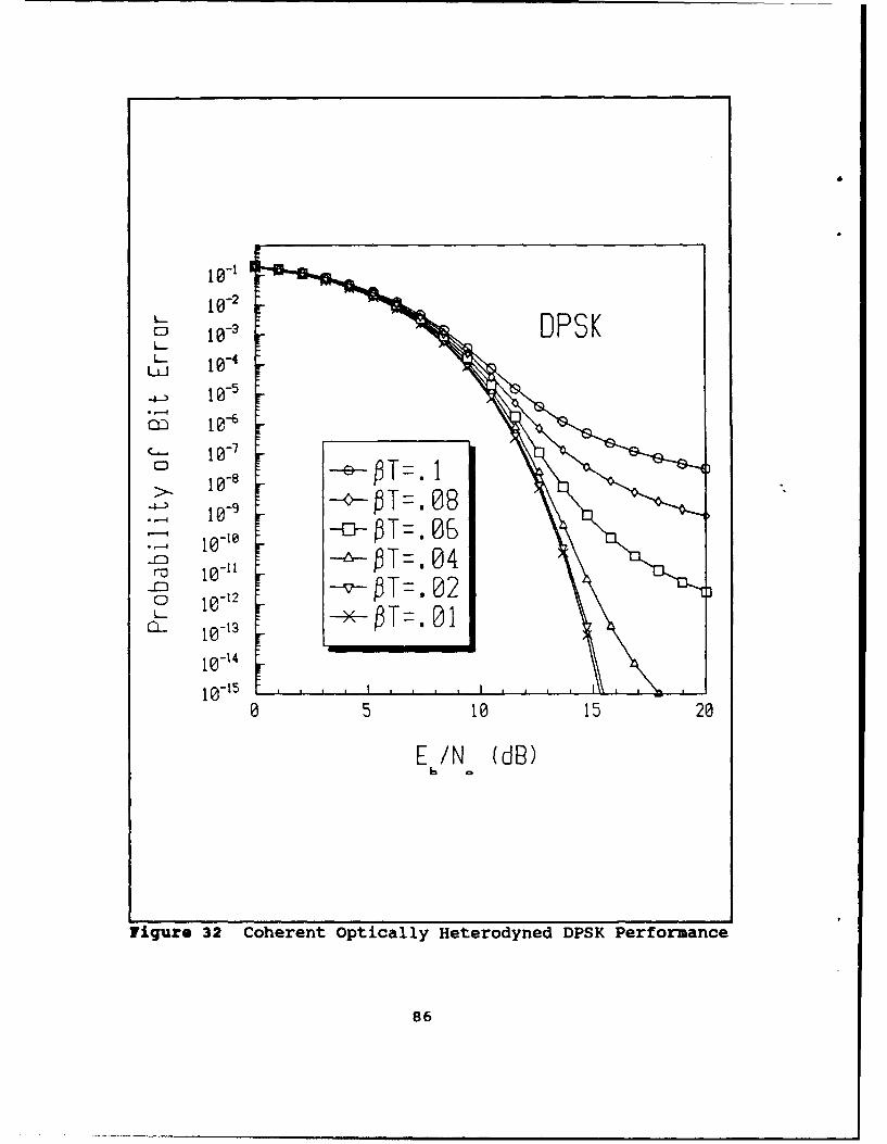
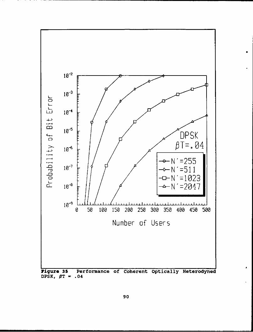
C. Differential Phase-Shift Keying ........... 85
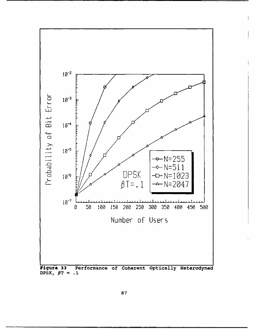
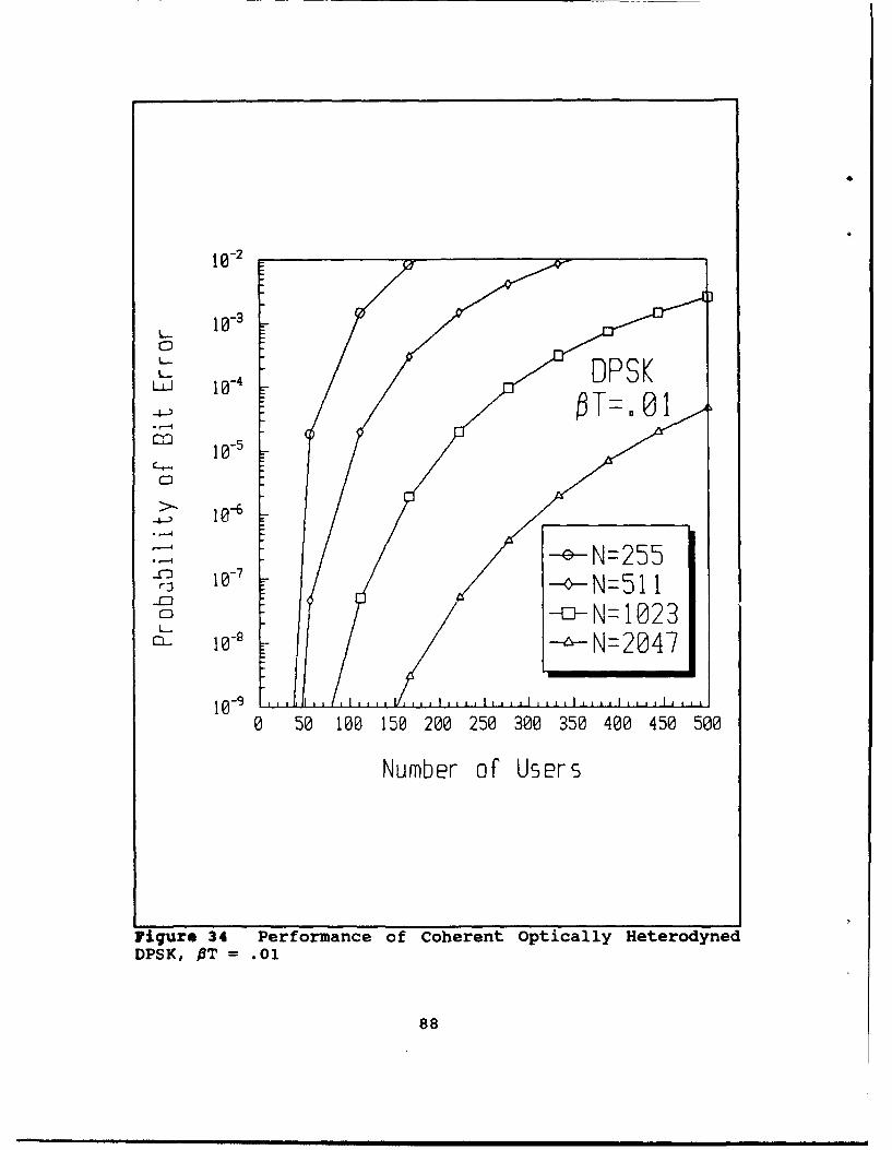
D. DPSK-CDMA ......... . . ....... o.. ....... 85
VI. CONCLUSIONS......................91
REFERENCES .. .. .. .. .. ... .. ... ... .. 94
INITIAL DISTRIBUTION LIST .................. 96
vi
Page 8
I. INTRODUCTION
Optical fiber communications is undergoing an evolution
that is similar to that which occurred for conventional wire
and wireless communications. From the spark-gap transmissions
that were first sent over wire and then free space to the
spread spectrum techniques currently researched today, the
history of baseband and radio frequency communications
provides a direction for the development of improved optical
fiber communication systems. This is now possible due to the
advances in the research and development of coherent optical
fiber communication systems. A brief description of coherent
optical fiber communication systems will be developed followed
by a description of future optical fiber communication systems
proposed in this thesis.
Like the spark-gap transmissions of Morse Code over wire
and then free space, optical fiber communications originated
as an incoherent communication method in order to transfer
information, that is intensity modulation followed by direct
detection. For optical communications, incoherent
communication implies that a coherent carrier, that is, a
stable frequency oscillator, is not required for transmission.
A wideband light source such as an incandescent light or light
emitting diode can be used. Therefore, no information is
present in the frequency or phase of the signal. Only the
Page 9
amplitude of the signal is varied in order to transmit
information. Intensity modulation implies that the light
intensity is modulated linearly with respect to the input
signal voltage. To date, intensity modulation has been the
standard modulation technique in optical fiber communications.
Detection of these signals is not sophisticated since no
frequency conversion or any other signal processing is
involved. Direct detection is used to receive this signal.
Direct detection implies that the signal is detected at the
optical stage of the receiver. For direct detection of
intensity modulated signals, information is obtained by
detecting the presence or absence of a transmission by
receiving optical energy above or below some threshold level.
This is analogous to on-off keying (OOK) baseband signalling
used in digital communication systems.
In contrast to incoherent optical communication methods,
coherent optical communications techniques depend on a stable
oscillating frequency carrier for transmission which is then
modulated by an information signal. For these techniques the
information is transmitted in the frequency or phase of the
signal. Bandpass signalling such as amplitude-shift keying
(ASK), frequency-shift keying (FSK), and phase-shift keying
(PSK) are examples of coherent communication methods.
Three types of detection methods exist for coherent
optical communications: direct detection, heterodyne
detection, and homodyne detection. One can easily confuse
2
Page 10
coherent optical communications and coherent signalling.
Coherent optical communication exists when the information of
the signal is modulated on a stable frequency carrier thus
allowing either homodyne or heterodyne detection. This
requires the linewidth of the transmission source to be
relatively narrow. The linewidth of the transmission source
is the possible range of frequencies over which the source
will vary. An electronic receiver example is a microwave
oscillator which typically has a linewidth on the order of
magnitude of 1 Hz [Ref. l:p. 2156]. For optical
communications, the best linewidth that has been achieved to
date for semiconductor lasers is on the order of magnitude of
10 kHz [Ref. 2:p. 9]. On the other hand, coherent signalling
implies that information is present in the signal phase. For
coherent signalling both the frequency and phase of the
incoming signal are matched at the receiver by a reference
signal in order to detect that signal.
For direct detection, the detector converts the modulated
optical signal to a baseband signal which contains the
information frequencies. Direct detection is considered a
coherent optical communication detection method if a stable
oscillator is used as the carrier. As stated above direct
detection is used to detect the presence or absence of an
optical signal above some threshold value to yield a binary
result. Direct detection is also used to yield an output that
contains frequency information resulting in an analog signal.
3
Page 11
In either case, the direct detection method is a relatively
easy and cheap method 3f optical detection since no frequency
conversion or signal processing is required.
Heterodyne detection involves the optical combining of the
signal beam with a local oscillator beam before detection.
The local oscillator beam is at a different frequency than the
signal beam, but the two beams must have a high degree of
monochromaticity and the same polarization. The two beams
form an interference pattern at the detector. The output of
the detector is modulated at the difference frequency of the
two beams. This is also knoin as the intermediate frequency
(IF). Currently, for coherent optical communications, the IF
is chosen to be at radio frequencies (RF) so that conventional
RF demodulation methods can be performed on the signals
electronically. Heterodyne communications offers improved
sensitivity at the cost of a more sophisticated and more
difficult method of detection.
Homodyne detection is a special case of heterodyne
detection. For homodyne detection, the frequency and phase of
the local oscillator are controlled so that they match that of
the incoming signal beam. This corresponds to coherent
detection previously discussed. Even though this method
theoretically provides the best performance of the three
detection methods for coherent optical communications, it is
also the most difficult to implement.
4
Page 12
Over approximately the past ten years, coherent optical
fiber communication has been heavily studied and documented.
During the early development of optical fiber communications,
much of the improvements were due to advances in optical
sources and fiber technology. The reception of optical
signals was not significantly affected. With improvements in
narrowing the linewidth of optical sources, the practical
realization of coherent optical fiber receivers became
possible.
The benefits of coherent optical communication systems are
improved receiver sensitivity and improved frequency
selectivity. These benefits can only be achieved by using
more sophisticated transmitters and rceivers. Here, receiver
sensitivity refers to the minimum amount of received signal
power which is required to produce a prescribed bit error rate
[Ref. 3:p. 16]. The improved receiver sensitivities for
optical communication systems allows increased repeater
spacing in preexisting optical fiber systems. Increased
frequency selectivity allows more channel capacity and better
utilization of the enormous bandwidth available on optical
fibers. The increased frequency selectivity is exploited in
this thesis for the development of the coherent optical
heterodyne multiple access communication system.
This thesis concentrates on the detection of coherent
optical heterodyne signalling. As stated above, one of the
benefits of coherent optical heterodyne communications is
5
Page 13
improved sensitivity of the receiver. The heterodyne
detection method with its strong local oscillator drastically
reduces the effect of thermal noise and shot noise in the
receiver, therefore requiring less signal power in order to
accurately detect an incoming signal. Unfortunately, the
effect of laser phase noise is now a factor. Laser phase
noise is an inherent part of semiconductor lasers and is due
to sudden phase shifts which occur due to spontaneous emission
events within the laser. This causes a broadening of the
laser linewidth and is referred to as laser phase noise. For
heterodyne communication systems, both the transmit and the
local oscillator lasers contribute to the laser phase noise.
The effect of laser phase noise is minimized by increasing the
symbol rate. In this work, the performance of both multiple
frequency-shift keying (MFSK) and differential phase-shift
keying (DPSK) receivers in the presence of receiver thermal
noise, photodetector shot noise, and laser phase noise will be
examined for coherent optically heterodyned communication
systems.
Another problem that is addressed in this thesis is how to
provide access to the system for increasing number of users
without having a dedicated channel for each user. Currently,
wavelength division multiplexing (WDM) is used to provide a
more efficient use of the bandwidth of the optical fiber by
allowing multiple users. For this thesis, a code division
multiple access (CDMA) system using the heterodyne receiver
6
Page 14
with DPSK and MFSK demodulation will be investigated. The
benefits of using CDMA over WDM is that the multiple users
share the entire channel's bandwidth and their access is
asynchronous with no waiting or scheduling is involved. This
receiver is a combination of coherent and noncoherent
detection. The CDMA must be recovered coherently while the
MFSK and DPSK is decoded noncoherently. The goal of this
thesis is to perform a probability of bit error analysis for
various signal-to-noise ratios, laser phase noise values, and
multiple users.
The next chapter contains a description of the system.
Tnis includes a brief description of the components of the
communication system, MFSK, MFSK-CDMA, DPSK, and DPSK-CDMA
receivers as well as a discussion of the noise terms involved.
Chapter III is an analysis of the MFSK and MFSK-CDMA systems
with laser phase noise. Chapter IV is an analysis of the DPSK
and DPSK-CDMA systems with laser phase noise. Chapter V
contains the numerical results with the conclusions in Chapter
VI.
7
Page 15
II. SYSTEM DESCRIPTION
This chapter describes the proposed coherent optical
heterodyne communication system. First, the basic coherent
optical communication system is introduced including a
discussion of the components involved. This is followed by a
description of the proposed MFSK and MFSK-CDMA detectors and
then a description of the DPSK and DPSK-CDMA detectors.
Finally, the various noise terms present in the coherent
optical heterodyne communication system are discussed.
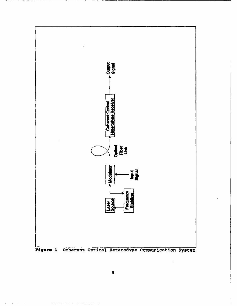
A. SYSTEM COMPONENTS
The coherent optical heterodyne communication system
proposed consists of an optical transmitter, a fiber optic
transmission medium, and a receiver. The receiver is
comprised of an optical mixer, a photodetector, and an IF
demodulator. After the received signal is optically
heterodyned and detected, further demodulation of the signal
is performed electronically. A simple block diagram of this
system is shown in Figure 1. A description of the system
components follows, including the requirements imposed on the
components for coherent optical communications.
1. Transmit Laser and Local Oscillator Laser
One of the challenges facing coherent optical
heterodyne communications is the availability of single
8
Page 16
co
:3I.L
Figure I. Coherent Optical Heterodyne Communication System
9
Page 17
frequency lasers with high spectral purity and frequency
stability. This requirement holds for both the transmit laser
and the local oscillator laser. This stable frequency
requirement eliminates the use of wideband sources such as
incandescent light or other incoherent light sources such as
light emitting diodes (LED's) which were used in early optical
fiber communication systems. Gas lasers are also disregarded
for practical systems due to size and safety considerations,
even though HeNe lasers have been used in some experimental
applications (Ref. 2]. This leaves semiconductor injection
lasers as the obvious choice for both the transmit and the
local oscillator laser due to its size and compatibility with
electronic circuits.
In order for a semiconductor laser to meet the
frequency stability requirements for coherent optical
heterodyne communications, a feedback loop can be used to
cancel any frequency variations in the laser. Distributed
feedback lasers (DFB's) have been used to detect ASK and FSK
noncoherently, i.e., envelope detection, without using a
feedback path. The transmit and local oscillator lasers had
linewidths 10 MHz and 50 MHz, respectively. Another scheme
used to detect DPSK employed a DFB laser which had a linewidth
reduction from 100 MHZ to 500 kHz due to an external feedback
loop. (Ref. 2]
10
Page 18
2. Modulator
Since high spectral purity is required from the
sources, modulators that do not add noise to the signals are
required. External modulators using lithium niobate (LiNbO)
crystals have successfully been implemented for ASK, FSK, and
PSK for bandwidths up to 30 GHz [Ref. 4:p. 431). The LiNbO
devices are electro-optic devices that modulate the optical
wave based on an electric input signal.
3. optical Fiber Link
Single mode or multimode fibers are the possible
choices for the transmission medium for optical fiber
communications. The single mode fiber has the major drawback
of low coupling efficiency of the optical power from the
source into the fiber because of its narrow diameter. The
multimode fiber has the drawback of increased pulse spread and
dispersion. The most important consideration for coherent
optical communication systems is the ability to maintain
polarity. This requirement directs the use of single mode
fiber for the transmission medium of coherent optical
communications.
The received signal and the local oscillator must be
coaligned in linear polarization in order to achieve the
maximum signal output for detection. One way that this
polarization can be maintained is to use polarization-
maintaining optical fibers as the transmission medium.
11
Page 19
However, if a coherent optical heterodyne communication system
is to be implemented on an existing optical fiber link that is
not polarization-maintaining, then the polarities of the
incoming signal and the local oscillator can be matched by use
of polarization-diversity receivers or polarization
controllers. Polarization matching is important for proper
system operation but is beyond the scope of this thesis. The
assumption will be made that the polarizations are matched for
the proposed system so that the maximum signal energy is
detected.
For a multiple random access scheme, several users
transmit over the same optical fiber link. In order to
implement this type of system, the different users' optical
power must be combined at the transmitter outputs and
subsequently split at the receiver inputs for each of the
users. This can be achieved by the use of N/1 optical
couplers and 1/N optical decouplers where N is the number of
possible users that can have access to optical fiber link.
WDM communication systems use this configuration, which is
known as the broadband-multiplexing technique [Ref. 4:p. 395].
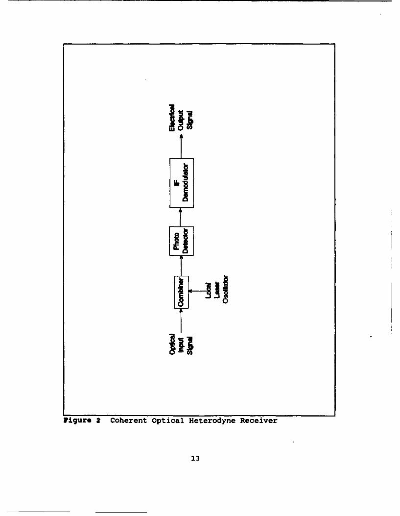
4. Receiver
The receiver of a coherent optical heterodyne
communication system consists of an optical mixer, a
photodetector, and an IF demodulator. A simple block diagram
of this system is shown in Figure 2. The incoming optical
12
Page 20
1:
Figure 2 Coherent Optical Heterodyne Receiver
13
Page 21
signal is combined, or mixed, with the local oscillator
optical beam. The combiner ensures that the incoming optical
signal beam and the local oscillator beam are matched in
polarization to ensure a maximum signal strength at the
photodetector. The combination of the two light beams form an
interference pattern on the photodetector at the difference
frequency, or IF, of the two beams. The optical signal is
then converted from an optical signal to an electrical signal
by the photodetector. Now, the signal is demodulated
electronically by the IF demodulator. For this thesis, the
noncoherent detection methods DPSK and MFSK are analyzed.
5. Detector
Two types of detectors are considered for this system:
the PIN photodiode and the avalanche photodiode (APD). In the
PIN photodiode, the incoming optical signal energy causes the
release of free electrons into the conduction band of the
semiconductor resulting in an output current. Ideally, each
photon creates an electron-hole pair; however, due to
recombination, the quantum efficiencies are less than 100%.
In the APD, an incoming photon creates an electron-hole pair;
but due to the intense electric field in the semiconductor
material, more electron-hole pairs are generated resulting in
an internal gain for the device. Even though a larger output
current per photon results, the speed of response is much
slower. Since the proposed coherent optical heterodyne
14
Page 22
communication system to be examined in this thesis is a high
data rate multiuser system, the PIN-FET photodiode shows the
most promise [Ref. 5:p. 1296].
B. FOSE AND MFSK-CDMA DEMODULATOR
One of the IF demodulators analyzed in this thesis is the
noncoherent MFSK demodulator. For multiple orthogonal
signalling such as MFSK, several bits are selected to
represent a symbol. A symbol is then transmitted as one of M
possible waveforms. In 8-ary MFSK for example, three bits are
chosen as a symbol, and one of eight possible frequencies are
transmitted depending on the bit pattern and frequency
assignments. The frequencies must be selected with proper
separation to ensure orthogonality.
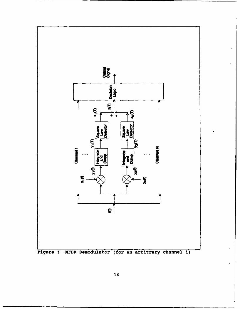
A block diagram of the MFSK demodulator is shown in Figure
3. The input to the demodulator is the IF output from the
photodetector which results from the optical heterodyning of
the incoming optical signal and the local laser. The MFSK
demodulator consists of M branches of quadrature demodulators
each matched to one of the X frequencies. Simpler receiver
structures for MFSK such as matched filters and envelope
detectors are not used since the MFSK-CDMA signal cannot be
recovered with this type of receiver. Each of the branches of
the quadrature demodulator mixes the incoming signal with in-
phase and quadrature-phase signals at the branch frequency.
The signals are then integrated and sampled over the symbol
15
Page 23
I!
e e
Figure 3 MFSK Demodulator (for an arbitrary channel i)
16
Page 24
period. The in-phase and quadrature-phase components are then
recombined at the output of the square law detector. If an
incoming signal frequency is one of the M frequencies, then an
output signal will be present in that branch. The other
branches will only have noise present. The output of the M
branches are then input to the decision logic which chooses
the largest signal level and decodes the signal to a
prescribed bit pattern.
The MFSK-CDMA demodulator differs from the MFSK
demodulator in that it is a combination of both coherent and
noncoherent demodulation schemes. The noncoherent
demodulation of the MFSK is identical in both demodulator.
The difference is that the user code that was used to spread
the bit stream must be coherently demodulated. In order to
recover the bit stream, the user sequence is modulated onto
the local oscillator of the quadrature demodulator. The user
sequence generated at the receiver must match that of the
transmitter. Hence, coherent demodulation of the CDMA signal
is required. An analysis of both the MFSK and MFSK-CDMA
receivers is performed in the next chapter.
C. DPSK AND DPSK-CDMA DEMODULATOR
The second modulation scheme analyzed in this thesis is
DPSK. For this communication scheme, each bit that is
transmitted is encoded depending on its value and the value of
the previous bit. The actual encoding scheme can be performed
17
Page 25
in several different ways which are essentially variations of
the description which follows. First, an initial code bit is
assumed either a "0" or a "1". This code bit is then compared
to the message bits that are to be transmitted. Each bit
comparison results in a subsequent code bit. One method of
creating the code bits is to allow the code bits to remain the
same as long as the information bits match the code bits and
change polarity when they do not match. The code bit sequence
represents how the phase of the carrier is modulated. For
example, a "0" code bit represents no phase shift and a "1"
represents a 1800 phase shift in the carrier.
Since two bits are compared in generating the code, then
it seems at first glance that four combinations of bit
patterns have to be detected at the receiver. This is not the
case. Recovery of the DPSK signal is performed simply by
noting whether or not a difference occurs between two
subsequent bits. As long as the initial bit in the sequence
is known, then the transmitted bit stream can be recovered.
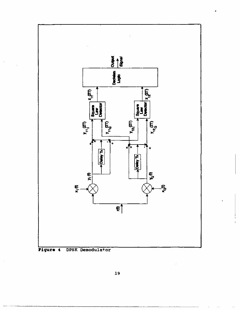
The DPSK demodulator is shown in Figure 4. The upper
channel of the demodulator has a signal present when a bit is
the same as the previous bit transmitted. The lower channel
has a signal present when a bit is different from the previous
bit transmitted. The signals are first mixed with a local
oscillator to break the incoming signal down into its in-phase
and quadrature components. Next, the signals are delayed and
the added/subtracted for the upper/lower channel in order to
18
Page 26
4Ii
Figure 4 DPSK Demodulator
19
Page 27
determine if the current and previous bits are the same or
different. Finally the in-phase and quadrature-phase
components are reconstituted by the square law detector to
form the detection statistic.
In a manner similar to the MFSK-CDMA demodulator, the
DPSK-CDMA demodulator is a combination of coherent and
noncoherent detection. Once again the CDMA must be recovered
coherently. This is achieved by applying the user code
sequence to the local oscillator of the quadrature receiver.
Once the bit stream is recovered from the chip sequence, the
DPSK signal is demodulated noncoherently as described above.
D. NOISE SOURCES
The sources of noise are an important consideration in the
analysis of any communication system. Just as important are
the assumptions made regarding the noise. For the coherent
optical heterodyne communication system with CDMA, four noise
sources affect system performance: laser phase noise, receiver
thermal noise, photodetector shot noise, and multiuser noise.
1. Laser Phase Noise
Since semiconductor lasers have been chosen as the
source for the transmitter and the local oscillator of
coherent optical communication system, laser phase noise can
have a significant impact on system performance. Laser phase
noise is a random process which occurs because of spontaneous
emission within the laser cavity. This causes the phase of
20
Page 28
the optical output wave to execute a random walk away from the
value that it would have if spontaneous emission did not occur
[Ref. l:p. 2156). *This random phase process is evident by
observing the broad linewidths of semiconductor laser emission
spectrum.
The broad linewidth caused by laser phase noise on a
laser transmitter or local oscillator has several effects. If
the linewidth is large with respect to the signal frequency,
then it is impossible to recover any timing or phafe
information from the signal. For example, for a homodyne
detector where phase tracking is necessary, a linewidth on the
order of 10 kHz is required for recovering information on a
100 Mbs system (Ref. 2:p. 11]. Also for high data rate
systems and multiuser systems, an excessive linewidth limits
the range of frequencies over which the transmit laser can be
modulated. For optical heterodyne detection, the laser phase
noise present in the system is the sum of the transmit laser's
phase noise plus the local oscillator's phase noise.
Laser phase noise is caused by randomly occurring
spontaneous emission events in the laser which cause sudden
jumps in the phase of the electromagnetic field generated.
The laser phase noise can be modelled as a random walk
process. As the time between steps approaches zero, the
random phase becomes a Brownian motion process characterized
as a zero mean, white Gaussian process. The power spectral
density of the laser phase noise is the integral over the
21
Page 29
frequency band of operation of the Gaussian process which
results in the Lorentzian spectrum. This can be determined
experimentally by measuring the frequency fluctuations of the
emitted light, or by observing the laser emission spectrum.
The linewidth is determined by measuring the 3 dB bandwidth of
the laser emission spectrum. [Ref. 1]
Even though the random walk process of the laser phase
noise can be simulated in order to determine system
pqrformance, it rapidly becomes computationally prohibitive
when the performance analysis is determined down to magnitudes
of 10 9. A closed form probability density function of a
random variable that describes the effect of laser phase noise
on the signal has been determined empirically by measuring the
output envelope of various bandpass filters. A data rate of
at least three times the laser linewidth is required in order
for this probability density function to be valid.[Ref. 6]
The laser phase noise models and the proposed data rates of
operation will be discussed further in later sections.
2. Receiver Noise
Receiver noise that contributes to the degradation of
the communication system is a combination of receiver thermal
noise and photodetector shot noise. Thermal noise is shot
noise that is generated in the resistive components of the
receiver. Photodetector shot noise results from the fact that
photons and electrons occur in discrete values. For coherent
22
Page 30
heterodyne optical communication systems, a strong local
oscillator is combined with the incoming optical signal.
Since the number of events is increased for the shot noise
process, then it can be assumed that the shot noise can be
modelled as a zero mean, white Gaussian process. This allows
both receiver noise terms to be combined and treated as a zero
mean, white Gaussian noise process.[Ref. 1]
3. Multiuser noise
To improve multiple access for the coherent optical
communication system, MFSK-CDMA and DPSK-CDMA are both
considered. These methods make efficient use of the available
bandwidth by providing asynchronous access to each user and by
providing the entire bandwidth for each user's transmissions.
Unlike other multiple access schemes that exist, CDMA has the
advantage of no waiting and no collisions by the users. For
CDMA, each user codes their transmissions to spread their
signals over the available bandwidth. Ideally, each user code
is orthogonal to all others, so each user is transparent to
the others using the same bandwidth. In reality each user's
receiver cross correlates some of the other users' signals.
This interference due to other users is multiuser noise.
Obtaining a mathematical relationship for the effect of
multiuser noise in CDMA has been widely studied. In many
cases, multiuser noise can be represented as a Gaussian random
process. This assumption is valid as long as the spreading
23
Page 31
code length and the number of users is large enough to invoke
the central limit theorem.[Ref. 7] The MFSK-CDMA and DPSK-
CDMA systems to be investigated are high data rate systems
with long spreading codes to maximize the number of users.
24
Page 32
III. ANALYSIS OF MFSK AND MFSK-CDMA
This chapter presents the probability of bit error
analysis of the MFSK and the MFSK-CDMA systems. First, the
conditional probability density function of the random
variable that represents the decision statistic, Zi, is
derived. Then, the probability density function of the random
variable that represents the effect of laser phase noise is
introduced. This allows the determination of the probability
of bit error for the MFSK system. The noise term that models
the interference of the multiusers is then added to the
analysis to obtain the probability of bit error for the MFSK-
CDMA system.
A. The Conditional Probability Density Function of Zi
The received signal, r(t), arriving at the input of the
MFSK demodulator shown in Figure 3 results from the
heterodyning of the transmitted optical signal with a local
laser oscillator which is then converted to an electrical
signal by the photodetector. This received signal is a
combination of the signal and noise
r(t) = si(t) + n(t) (1)
where n(t) represents the receiver thermal noise and
photodetector shot noise. This is assumed to be a zero mean,
25
Page 33
white Gaussian process. The signal portion, s1(t), i = 1,
... , M, contains one of the orthogonal MFSK signals, and a
random phase. The signals are assumed to be equally likely
and have equal energy. The signal is represented as
si(t) = Re[b(t)exp(jw1 t)] (2)
where
b(t) = -sexp[jO(t)] (3)
is the normalized complex baseband signal. The magnitude is
normalized, with E. as the symbol energy of the signal and Ts
as the symbol period. The phase term, 8(t), is the composite
phase noise due to the transmit and local oscillator lasers.
The received signal is multiplied by orthogonal signals to
form the in-phase and quadrature components on each of the M
channels. These signals form an orthonormal basis set and are
matched to the frequency of that channel. The signals for an
arbitrary jth channel are
(t) = 2-cos(%t) (4)
XQj t) = .2sin(jt) (5)
26
Page 34
After the in-phase and quadrature components are formed,
the received signal is then passed through an integrate and
dump circuit. The random variables defined to represent the
output of the integrate and dump circuit are
ToY"' (Tg) = fr (t)x,(t) dt (6)
0
and
To
= fr(t)x,(t)dt (7)0
where j = 1, ... , M. For the case when i is not equal to j,
y1,(TO) = n. , yo,(TO) = n. , (8)
where n, and n. are zero mean white Gaussian noise processes
with variance N0/2. When i = j,
Y AfT, T
y1 (T') = fcoseWdt +n (9)0
and
T,
y",(T.) = fsinO(t)dt + n(goo
The random variable that represents the detection
statistic, Z1, is formed by summing the output of the square
law detectors of the two quadrature branches in each of the M
channels shown in Figure 3. From the results in Equation (8),
27
Page 35
the conditional probability density function for Z, when i is
not equal to j [Ref. 8:p. 109) is
p(zj) = -Iexp(--.L) (11)
202 202
When i = j, the conditional probability density function for
Zi is a noncentral Chi-squared distribution [Ref. 8:pp. 113-
115]. Since
ZI (T.) = [y,(T)]2 + [YO,(T ' )] 2 (12)
then by using Equation (9) and Equation (10), the conditional
mean of the noncentral Chi-squared distribution isE, ] ro 1t
S cs(T(t))d [To fsin(O(t))dt]2(13)
This is simplified to
)L-E fexp[ (t)] 12dt (14)0
If the random variable X (Ref. 9:p. 309] is defined such that
x = I-Lfexp[j (tdti (15)
then the conditional mean for the Chi-squared distribution is
S=EwX2 (16)
With these results, the conditional probability density
function of Zi when i = j is
28
Page 36
p(z 1 x) = -Lexp[- z, + E'X[2 1 r (17)
where I0 is a zero order modified Bessel function of the first
kind and 202 is the variance of the additive white Gaussian
noise [Ref. 8:p. 114]. This result is conditioned on X which
results from the laser phase noise. This can be eliminated as
shown
P(Z) = fP(zI z=z,x(X X (18)0
B. Probability Density Function of X
As stated in Chapter II the laser phase noise is modelled
as a random walk process from the value it has when no laser
phase noise is present. A straightforward approach to
evaluate the integral which defines the random variable X
using Monte Carlo simulation has proven to be computationally
intensive. Another approach to determine the probability
density function of X has been to observe the output envelope
of a bandpass filter. For a given impulse corrupted by laser
phase noise, the filter response becomes a random process
whose envelope at any instant in time is a random variable.
This approach results in a closed form analytical solution for
the probability density function of X by use of a curve fit
29
Page 37
approximation to the actual probability density function. The
probability density function of X used in this analysis is
pX(x) = a[l - exp(-a)]'1exp[-a(1 - x)] for 0 s x s 1 (19)
0 otherwise
where
= 1.6 .- (1 + V) (20)
This probability density function assumes that an integrate
and dump filter is used with rectangular signal pulses. In
addition to the dependence on the filter type and the
signalling chosen, the probability density function of X also
depends on the laser linewidth, P, and the symbol period, T6.
(Ref. 6)
C. Probability of Bit Error for XFBK
The derivation of the probability of bit error for an MFSK
system is developed by first finding the probability of
correctly detecting a symbol. From this, the probability of
symbol error is easily determined. The probability of symbol
error is then converted to the probability of bit error. The
analysis is performed by observing the statistics of the
decision variable of an arbitrary channel. The decision
variable, Zi, results from the summation of the in-phase and
quadrature branches of one of the X channels in the MFSK
receiver as shown in Figure 3. As stated in Chapter II, the
30
Page 38
MFSK receiver is corrupted by laser phase noise, receiver
thermal noise, and photodetector shot noise.
For MFSK, the probability of correctly detecting symbol i
is the probability that Z, exceeds all the other decision
statistics given that the symbol i was transmitted. Let P.
represent the probability of correctly detecting a symbol.
Therefore,
PC = P(z 1<z. n ... n zfl<z, n z 1< z n ... n z<z) (21)
Rewriting in terms of the probability density function of Z,
we have
(22)PC P(Z1 <Zi, ... , Z- 1 <Zi, Z., 1 <Z1 , ... , Zm<Zi I Z1 =z 2 )p(z,)dz,
0
Since each of the decision statistics are assumed to be
independent, identically distributed random variables, the
joint probability is rewritten as
P,= [P(zj zi) ]Ip(z. ) dz i where i j (23)0
This expression can be simplified further since
P(ZJ-Zi ) = fp(zj) dzj (24)0
Substituting Equation (11) and Equation (24) into Equation
(23), we obtain
31
Page 39
[= f [f 1 exp(__.#I)dzJ]M- p(z 1 )dz (25)
0 0
Evaluating the integral for z,, we get
Pc = f [1-exp(-2Z')]"' p(z.)dz, (26)0202
Using the Binomial Expansion [Ref. 10:p. 347], we find the
probability of correct detection as
PC § pM1 (~)1~(~ (z.) dzi (27)o k-a 202
Substituting Equation (17) into Equation (27), we get
M1 ) )-e(k+ )z + E SX 2 1 E( E z
PC(x) = - I ( k olexp )dz10 2 0 202 a 2
(28)
To obtain a workable expression for the probability of
correct detection, the identity [Ref. 10:p. 404]
10( 2 ) = j (X ESzl)f [ 1 2 (29)a n- 4a4 (n!')
is substituted into Equation (28) to yield
-L 1 1)klx (k+ 1)z ri E'X2 - X2EZl d (30)
PW 20 2.2 404o (n!)2
After rearranging terms, we can express Equation (30) as
P,(x) - 1 I(2a2 20 404 (nlI) 20
Next, use the definite integral [Ref. 10:p. 337]
32
Page 40
fzinexp (k1) dzi n (32)202 (k-1)
2 n202
in Equation (31) to get
P'()- -- xp-i n, ](33)
20 2o2 t _ 40 [ (n )] (*+l))-I2a2
which can be simplified to
2A E')-[ 1 (34)
Finally, the expression
-- [ x2E ] = exp [ x2E - ] (35)n-0 n! (k+1) (2a2) (k+l) (202)
is used in Equation (34) to obtain the probability of
correctly detecting a symbol
P=(X) = exp(-E1) kM ) ()k-1 exp[ x2E, 6)
202 k-0 (k+l) (k+l) (202)
This is simplified further to
PC(x) = -1 ( MI) (-1)k-1___ exp[- (37)NO k (k+l) (k~l) (202)
The probability of symbol error is easily found from the
probability of correctly detecting a symbol as
e- M- kx2E, (38)P,(x) = 1 - P = . 1 )k(k+) (k_) ___l_)ex[ (2233 (k+l) (k+1)(2
33
Page 41
The dependence on the random variable, X, is removed by
averaging as follows
1 - 1 k x 2 E Vp. f T (M-1) (_i)jI exp[- ]p(x)dx (39)
0 1 (k4 l1) (k+1) (202)
In order to compare the system performance of this system
with other digital communication systems the signal to noise
ratio is expressed in terms of Eb and N.. If we substitute
02 = N- E, = Eblog2M, (40)2 g
into the above, then the probability of symbol error becomes
,- ( I1 _ kx 2 Eblog2 M]P = I Y1 ( 1) (- 1 )k-1 1exp- px(x)dx (41)0 k-i (k+l) (k+1) N
The probability of symbol error is converted into the
probability of bit error by [Ref. ll:p. 180]
P (M ] P. (42)2(M-1)
so that performance comparisons can be made with binary
communication systems. This results in the final expression
for the probability of bit error that is used in the numerical
analysis
1 (M -. 1) 1 kx 2Eblo2M"P- f [ (. --i exp[- IP dx
(43)
As a check, let the laser phase noise become negligible.
Hence,
34
Page 42
Px(X) 6 (x-) (44)
Evaluating the integral in Equation (43), we get the
probability of bit error
-1 I exp[ kEblog2M ] (45)
H [(M-I) () (k+l) (k+l)No
which compares to the probability of bit error for noncoherent
MFSK detection (Ref. 1l:p. 177]. For M = 2, the probability
of bit error reduces to
P EbPb = exp (-2N,) (46)
which corresponds to the probability of bit error expression
for noncoherent binary FSK [Ref. ll:p. 166]. The performance
of the MFSK-CDMA system is analyzed next by adding the noise
contributed by multiple users.
D. Probability of Bit Error for MFSK-CDMA
The MFSK-CDMA system allows multiple users asynchronous
access to the same channel. Ideally, each user will have use
of the channel with no interference from the other users. In
order to accomplish this, each user is assigned a code which
is used to modulate the carrier for each symbol that is
transmitted. The codes are ideally chosen to be orthogonal so
that only a particular user's code is demodulated at a
particular receiver. In a practical system, pseudo-noise
35
Page 43
codes generated from m-sequences or Gold codes, obtained by
the modulo-2 sum of two m-sequences, are used. Some cross
correlation noise occurs between the various users' when these
codes are used, and this degrades system performance.
The difference between the MFSK receiver and the MFSK-CDMA
receiver is that the user's code is applied to the transmit
message. This causes the received signal from Equation (2) to
become
si(t) = Re[a(t)b(t)exp(jwit)1 (47)
where a(t) is the user code sequence. At the receiver, the
user's code must also be applied to the in-phase branch
multiplier from Equation (4)
x1 L(t) = WTsa(t)cos(wit) (48)
and the quadrature branch multiplier from Equation (5)
L(t) = Ja(t)sin(it) (49)
for each channel. The user code sequence at the receiver must
be synchronized to the transmitter's user code, therefore
requiring coherent detection of the code sequence. After this
is performed, the signal is noncoherently detected by the MFSK
demodulator as previously discussed.
The multiple user noise model used in this analysis is
derived for asynchronous MFSK detection where random signature
36
Page 44
sequences are used. Random signature sequences are not
physically realizable but are used in mathematical analysis to
simplify the noise expression due to the multiple users. It
has been demonstrated that random sequences and Gold codes
yield comparable performance [Ref. 12:p. 598]. For the model
used it is assumed that the user's transmission are not
synchronized, that the user's transmit at equal power, and
that the data streams, time delays, and phase shifts are
mutually independent random variables.
The average probability of bit error for MFSK-CDMA is
approximated by using a zero mean, white Gaussian noise random
variable for the multiple access interference. The noise
variance is [Ref. 7:p. 692)
02 _ NO + (K-1)E (50)
2 3IN'
where N.12 is the two-sided power spectral density of the
additive white Gaussian receiver discussed previously, E. is
the symbol energy, M is the order of signalling, K is the
number of users, and N' is the length of the spreading code.
37
Page 45
IV. ANALYSIS OF DPSK AND DPSK-CDMA
This chapter develops the probability of bit error for the
DPSK and DPSK-CDMA systems. The conditional probability
density function of the decision statistic is derived first.
The probability density function of the laser phase noise is
then restated noting the differences with that which was used
for the MFSK case. Finally, the probability of bit error is
developed for the DPSK system. The multiuser noise is then
added to the analysis resulting in the probability of bit
error for DPSK-CDMA.
A. Conditional Probability Density Function of Z1 and Z3
Similar to the MFSK case, the received signal, r(t), at
the input of the DPSK demodulator is the result of the
heterodyning of the optical signals from the transmit laser
and the local oscillator laser as shown in Figure 4. The
received signal is a combination of the signal and noise
r(t) = s(t) + n(t) (51)
where n(t) represents the receiver thermal noise and
photodetector shot noise. This is assumed to be a zero mean,
white Gaussian process. The signal portion, s(t), contains an
IF frequency whose phase is modulated based on the coding
scheme described in Chapter II. The signals are assumed to be
38
Page 46
equally likely and have equal energy. The signal is
represented as
s(t) = Re[b(t) exp(jot) ] (52)
where
IEbb(t) -expj(e(t) +*4(t)) (S3)
Tb
is the normalized complex baseband signal corrupted by laser
phase noise. The magnitude is normalized with Eb, the energy
transmitted per bit, and Tb, the bit period. The phase term,
e(t), is used to represent the combined laser phase noise due
to the transmit laser and the local oscillator laser. The
phase term, *(t), represents the encoding performed on the bit
stream prior to transmission. The possible values of O(t) are
(0,).
The demodulation of the DPSK signal begins by first
multiplying the received signals with those of an orthonormal
basis set. This multiplication of the signals is performed
electronically by a mixer which translates the signal from IF
to baseband and forms the in-phase and quadrature components
of the complex baseband signal. The mixing waveforms are
X() = cos (W7 (S4)
N Tb
and
39
Page 47
XQ 0)= [2 sin(wl. (SS)xTb
After mixing, the received signal passes through an integrate
and dump circuit. The random variables defined to represent
the output of the integrate and dump circuit are
Tb
yz(Tb) = fr(t)x.(t)dt (56)
0
and
Tb
YQ(Tb) = fr(t)xQ(t)dt (57)0
Substituting Equation (51), (52), and (53) into Equations (56)
and (57) and simplifying, we obtain
Tb
yI(Tb) = /cos [0(t) + 4(t)]dt + n.(Tb) (5O)X ("b Tb f
and
Tb
yo(Tb) = f sin[e (t) + (t)]dt + no(Tb ) (59)Tb 0
where n, and n0 are zero mean, white Gaussian noise processes
with variance a2 = N012. Since *(t) can only take on the
discrete values (0,w), then Equations (58) and (59) can be
rewritten as
40
Page 48
-Eb rb(60)b
and
() - f fsin[o(t)]cos[4(t)]dt + nQ(Tb)
YO (Tb) =Tb
The next step in the demodulation of DPSK for the receiver
shown in Figure 4 is the formation of four signals represented
by the random variables: y111( 2 Tb), Y11Q( 2 Tb), Y121 ( 2 Tb), and
y12 (2Tb). As discussed in Chapter II, only two cases are
needed for the DPSK detection: when the message bit is the
same polarity as the previous message bit and when they have
different polarities. The signals in the upper channel, the
11 case, are represented by the random variables, y11,( 2 Tb) and
y11(2T b), each with a nonzero mean when adjacent message bits
are the same. The signals in the lower branch, the 12 case,
are represented by the random variables, Y121 (2Tb) and y12 (2Tb),
each with a nonzero mean when adjacent message bits are
different. Otherwise, the signals in each channel are
represented by zero mean random variables since only noise is
present. For example, only noise will be present in the lower
channel when the adjacent bits are the same, the 11 case.
This case is now developed.
The upper branch inputs to the square law detector in
Figure 4, y111 ( 2Tb) and y11 ( 2 Tb), are formed by adding the
41
Page 49
output of the integrate and dump circuit for two adjacent bit
intervals. For the in-phase component,
yL,(2Tb) = YI-(7b) + y1 (2 Tb) (62)
can be rewritten using the results from Equation (60) as
7 Tb
y111(2Tb) = f~ cose(t)cos4(t)dt nI(Tb)Tb 0
22Tb
'(b f cose(t)cosO( t) t + n.,( 2 Tb)Tb 7b
The sum of the two noise random variables results in a zero
mean white Gaussian process with variance 2a2 since the noise
is assumed to be an independent, identically distributed,
stationary Gaussian process. The adjacent bits are assumed to
have the same polarity, therefore cos[0(t)) has the same value
over both bit intervals, either both +1 or -1. Also, since
8(t) is an independent, identically distributed Brownian
motion process, then the expression for yIIJ(2 Tb) can be
rewritten as
+2 Tb
Y11(2Tb) T fcosO(t) dt + n,(64)-Tb 0
where n ° is a zero mean, white Gaussian noise process with
variance 2a2 discussed previously. Similarly, the quadrature
component for the 11 case can be written as
42
Page 50
yll( 2 Tb) + 2 fsinO(t)dt + lQ (65)
where n; is a zero mean, white Gaussian noise process with
variance 2a2. Note that the signs of Equations (64) and (65)
have no significance since they are input into a square law
detector. Therefore, the sign is dropped from further
analysis.
The lower branch inputs to the square law detector, Y121
and y,2, are formed by subtracting the output of the integrate
and dump circuit for two adjacent bit intervals. For the in-
phase component this becomes
y 1 2,( 2 Tb) = yI(Tb) - yz(2Tb) (66)
which can be rewritten using the results from Equation (60) as
Y, 2 (2 b) =_C~bTbY12 1 (2f) = fcoso(t) cos,(t)dt + nh(Tb) -Tb0a1~ (67)2 T
f coso(t)cost(t)dt - nI(2Tb)Tb Tb
The difference of the two noise random variables results in a
zero mean white Gaussian process with variance 2a2. This is
true since the noise is assumed to be an independent,
identically distributed, stationary Gaussian process. The
adjacent bits are assumed to have the same polarity, and 0(t)
is an independent identically distributed Brownian motion
process. Therefore, the integrals subtract out resulting in
43
Page 51
y,2,(2 Tb) =n." (68)
where n I is a zero mean, white Gaussian noise process with
variance 202. Similarly, the quadrature component can be
written as
y 1 29(2 Tb) = n, " (69)
where n0* is a zero mean, white Gaussian noise process with
variance 202.
The detection statistics, Z11 and Z12, are formed by
summing the outputs of the square law detector of the in-phase
and quadrature components for each case. Since the outputs of
the square law detectors for the 12 case are zero mean white
Gaussian noise processes, Equation (68) and (69), then the
conditional probability density function for Z,2 is [Ref. 8:p.
109)
p(z 12 ) exp (- Z12 (70)402 4 C2
The decision statistic, Z11, is formed by Gaussian random
variables with non-zero mean. Therefore, the conditional
probability density function for Z11 is written as a non-
central Chi-squared distribution [Ref. 8:p. 113-115]. Since
z,1(2Tb) = [yll (2rb) ]2 + [y,10 (2Tb) ]2 (71)
then the conditional mean of the noncentral Chi-squared
distribution is
44
Page 52
b fcs(8e(t))dt]2 + T f sin () (t)) dt] 2 (72)
This can be simplified to
A = 4 Eb e jTb(t) I dtl2dt
If the random variable X [Ref. 9:p. 309] is defined such that
Tb
x = - fexp[jO(t)dtl (74)Tb 0
then the conditional mean of the noncentral Chi-squared
distribution is
A - 4EX 2 (75)
The conditional probability density function of Z11 is
p(zai,x) -1exp[- z il + 4EbX2 xF ] (76)407 402 2a2
where 10 is a zero order modified Bessel function of the first
kind and a2 = N0/2 is the two sided power spectral density of
the white Gaussian noise [Ref. 9:p. 114]. This result is also
conditioned on X, which is determined by the laser phase
noise. The conditioning on X is eliminated as shown
I
P(zi= fp(z.x)p.(x) dx (77)0
45
Page 53
B. Probability Density Function of X
The model used for the probability density function of the
random variable, X, for this analysis is the same as that
which was introduced in Chapter III. The difference between
this expression and that of Equations (19) and (20) is the
expression for a. For MFSK, the integration occurs over the
symbol period, T,, compared to Tb for the DPSK demodulator.
Therefore, the probability density function of X used for the
DPSK and DPSK-CDMA analysis is
px(x) a [I - exp(-a)]'lexp[-a(i - x)] for 0 : x S 1 (78)
0 otherwise
where
=1.6a =--6(1 +0. 5V,/3Tb) (79)
0 Tb
This probability density function of X assumes that an
integrate and dump filter is used with rectangular signal
pulses. The probability density function of X also depends on
the laser linewidth, P, and the bit period, Tb. [Ref. 6]
C. Probability of Bit Error for DPSK
The average probability of obtaining a bit error depends
on the probability of detecting the 11 case when the 12 case
is transmitted plus the probability of detecting the 12 case
when the 11 case is transmitted. This is expressed
mathematically as
46
Page 54
Pb = P(Z1 1IH 12 ) P(H 2) + P(Z1 21H1I) P(H11 ) (80)
where H,, and H12 are the hypotheses that case 11 or 12 is
transmitted, respectively. Assuming equally likely
signalling, we have P(H 1 ) = P(H1 2) = 1/2. Also, using the
assumption that the probability of making an error is the same
for either case, we get
P= !P(Z11H2 + 2! (121H 11 ) = P(Z12j1Id (81)
2 21 H2 .(
The probability of bit error is now expressed using the
conditional probability density functions derived in the
previous section. The probability of bit error is
= fPr[z1 2,Z] p(zj)dz 1 (82)0
Knowing taat
Pr(Z1 2 >Z) = fp(z 12 )dz1 2 (83)Z11
and substituting this and Equation (70) into Equation (82), we
obtain
p, = f [f -exp (z'12)dz12] p(z11)dz11 (84)0 402 402
Evaluating the inner integral and substituting Equation (76)
into the result, we obtain
47
Page 55
Pb (x) 402 ex -z 0df 402 402 402 a2
0
This expression can be rewritten
2z, + 4Ev 2 bZ1Pb(x) =f 2-jexp( 2 z +dznj (86)
o 4 02
The identity [Ref. 10:p. 404],
10( 2 ) = ]- (x2Ebzll)o[ 1) (87)
o n-0 40 (n!)-
is substituted into Equation (86) to obtain
14E 1 ,X2 X2Eb) 1 ep(--)Z1 (88)P-(-x) -e (- exp(-o)z 1 1( dz4 (2 402 n-0 40 (n! ) 2 0 20cr2
= ° 0
In order to further simplify the expression, the definite
integral [Ref. 10:p. 337]
Z1 1 nexp( Z11 ) dz= nl ! (89)0 n+1 .202
is used in Equation (88) and the probability of bit error
becomes
Pb(x) = 2exp(-X2) 20 _L (90)2 02 ,,=a 202 n!
Since [Ref. 10:p. 349)
48
Page 56
(---) = exp (x2) (91)
202 n! 202
then
Pb = lexp (Ebx) exp ( x2Eb=) = lexp( - 2xEi) (92)
2 a 2 02C2 2 202
The final form of the probability of bit error for DPSK is
found by removing the conditioning on X and letting a2 = NW2
so that the probability of bit error is expressed in terms of
Eb and No . This results in
1 x2E
Pb(x) = f -exp- PxX) dx (93)
0
If the laser phase noise is allowed to become negligible, then
Px(X) = 6(x-l) (94)
and
Pb = exp(--E) (9s)
This result corresponds to the probability of bit error for
conventional DPSK communication systems [Ref. ll:p. 166].
Next, the performance of the DPSK-CDMA is analyzed by adding
the noise contributed by multiple users.
49
Page 57
D. Probability of Bit Error for DPBK-CDMA
The DPSK-CDMA system allows multiple users asynchronous
access to the same channel. Ideally, each user transmits and
receives on the channel with no interference from the other
users. This is achieved by assigning a code to each user
which is used to modulate the phase of the carrier for each
bit that is transmitted. The codes are ideally chosen to be
orthogonal so that only the user's code is demodulated at the
receiver. In a practical system, pseudo-noise codes generated
from m-sequences or Gold codes, obtained by the modulo-2 sum
of two m-sequences, are used. When used, these codes result
in some cross correlation noise in the receiver from other
users' codes. This degrades system performance. Obviously,
system performance worsens as the number of users increase.
The difference between the DPSK receiver and the DPSK-CDMA
receiver is that the user's code is applied to the transmit
message. This causes the received signal from Equation (52)
to become
s (t) = Re [a W b (t) exp (jct) 0] (96)
where a(t) is the user code sequence. At the receiver, the
user's code must also be applied to the in-phase branch
multiplier from Equation (54)
x,~t W LTa W cos (wt) (97)
and the quadrature branch multiplier from Equation (55)
50
Page 58
Xt) = F2-a W) sin (w 0 (98)
The user code sequence at the receiver must be synchronized to
the transmitter's code sequence. This requires coherent
detection of the code sequence. After the code sequence is
properly demodulated, then the signal is noncoherently
demodulated by the DPSK receiver discussed previously.
The model used for the multiple user interference for this
analysis is derived solely for DPSK detection using random
signature sequences. Several assumptions are made for this
model. First, the various users' transmissions are not
synchronized. Second, the users transmit with equal power in
the channel. Finally, the data streams, time delays, and
phase shifts are assumed to be mutually independent random
variables.
The average probability of bit error for DPSK-CDMA is
approximated by using a zero mean, Gaussian noise random
variable for the multiple access interference. The noise
variance is [Ref. 7:p. 692]
2_ No+ 2(K-1)Eb2 3N
The term, N/2, is the two sided power spectral density of the
additive white Gaussian receiver noise discussed previously.
51
Page 59
The term, Eb, is the average bit energy. The number of users
of the system is K, and the codelength implemented is N.
52
Page 60
V. NUMERICAL RESULTS
For the single user implementation of the coherent
optically heterodyned communication systems, numerical results
are obtained by evaluating the probability of bit error as a
function of EdNO for various PT. or PTb values. The
probability of bit error is the standard method of expressing
communication system performance, even when M-ary signalling
is used. The probability of bit error is expressed as a
function of Eb/NO rather than the signal to noise ratio (SNR)
in order to facilitate the comparison of one digital
communication system to another. The product of the laser
linewidth and the symbol period, PT., for MFSK or the product
of the laser linewidth and the bit period, PTb, for DPSK is
also used as a parameter for the evaluation of the probability
of bit error for MFSK and DPSK systems, respectively, when
corrupted by laser phase noise. In order to simplify the
discussion, the product of the laser linewidth and the time
period of integration will henceforth be referred to as PT for
both systems. This product allows the data rate of the
system, inverse of the time period of integration, to be
expressed in terms of the laser linewidth. A higher data rate
results in a lower PT for a given laser linewidth. This
yields general results that do not depend on a specific
transmit laser or local oscillator laser.
53
Page 61
For the multiple user implementation of the coherent
optical communication system, numerical results are obtained
by evaluating the probability of bit error for various number
of users, various codelengths, and a particular PT. Changing
the number of users of the system affects the amount of noise
that is present in the system. This is analogous to varying
Eb/NO. A maximum value of 16 dB is chosen for Eb/NO for all of
the systems analyzed. This yields a probability of bit error
of 10.9 for the M = 2, or binary, FSK case. This value is
chosen to anchor the comparisons of the probability of bit
error calculations of the MFSK and DPSK systems. For the
multiple user analysis, it is assumed that the optical signal
power is normalized to unity and that each user's transmit
power is balanced in the combined signal of the optical
channel.
All of the numerical analyses performed in this thesis
require numerical integration to obtain the probability of bit
error. This is performed using MATLAB. The results for MFSK,
MFSK-CDMA, DPSK, and DPSK-CDMA are presented next.
A. Multiple Frequency-Shift Keying
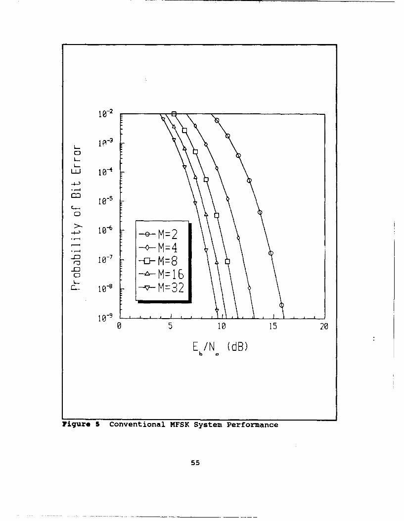
The probability of bit error for conventional MFSK is
computed first in order to obtain a reference for the
probability of bit error for the coherent optically
heterodyned MFSK system. Equation (45) is evaluated for
various Eb/N0 and is plotted in Figure 5. The five cases of
54
Page 62
10-2
CD
4--5
0
-vM=2
0 5= 10152
EIN (dB)
Figjure 5 Conventional MFSK System Performance
55
Page 63
MFSK that are analyzed (M = 2, 4, 8, 16, and 32) are shown.
From this figure the probability of bit error of io 9 is
obtained for the M = 2 case when EdNo = 16 dB. A performance
improvement of the MFSK system is observed as M increases.
This improvement occurs since the systems are compared for a
constant Eb/NO. As the number of bits per symbol increases,
the transmitted signal energy increases resulting in a higher
SNR. Obviously, the performance of the system improves as SNR
increases. This improvement in performance as M increases
occurs at the expense of requiring more bandwidth.
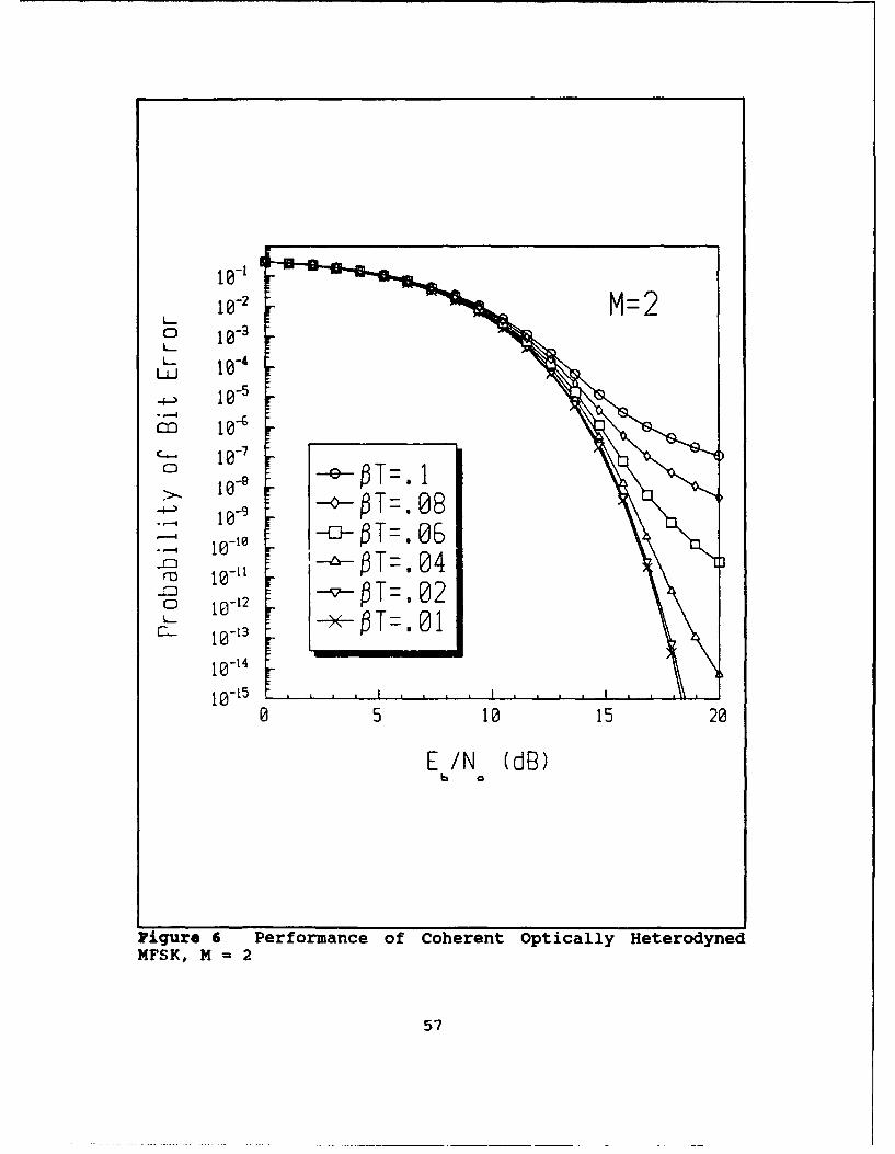
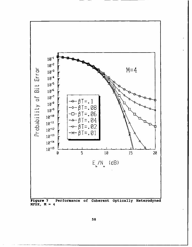
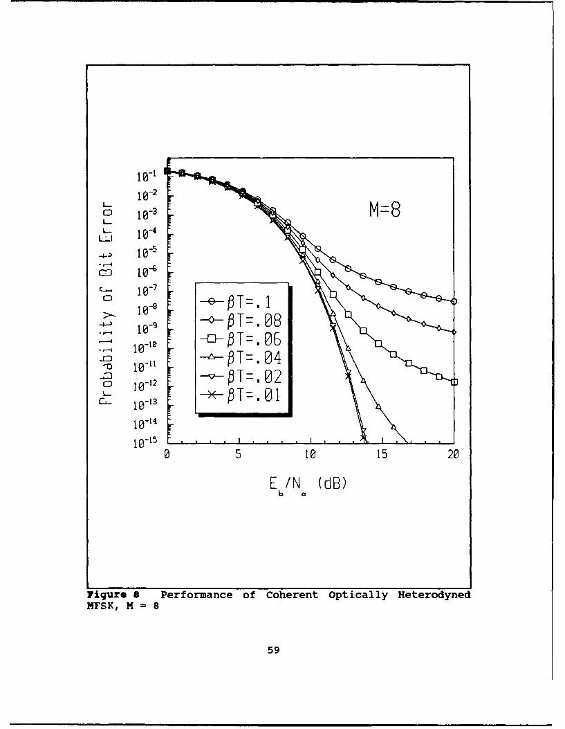
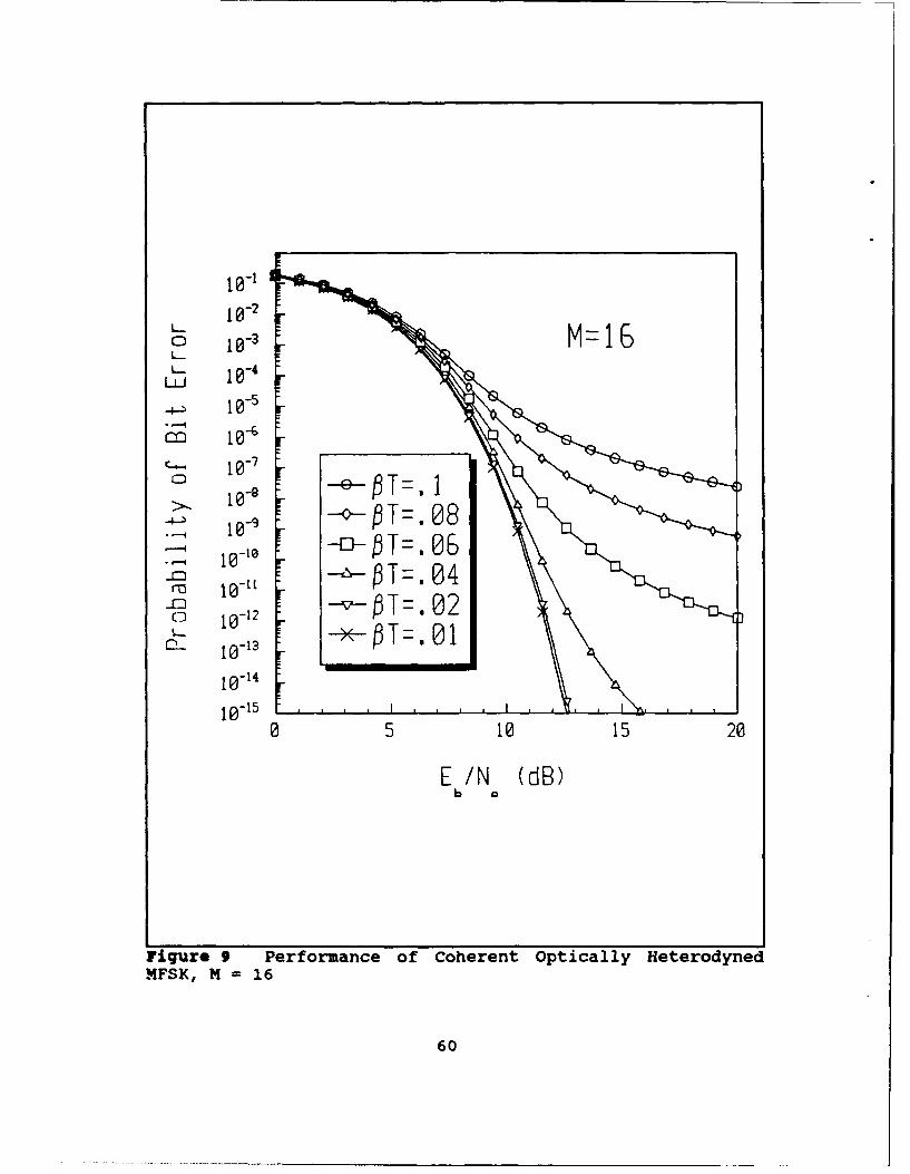
Each of the five MFSK cases when corrupted by laser phase
noise are calculated by numerically integrating Equation (43).
Each MFSK case with values of PT that vary from 0.1 to 0.01
are shown in Figure 6 through 10. As the symbol rate
increases from PT = 0.1 to 0.01, it is observed that the
effect of laser phase noise is less significant as expected.
The value PT = 0.1 is chosen as the upper limit since the
model used for the random variable, X, discussed in Chapter
III is only valid for PT < 0.3. The value of PT = 0.01 is
chosen as the lower limit for observation since the
probability of bit error approaches the case when no laser
phase noise is present. The five MFSK cases are next plotted
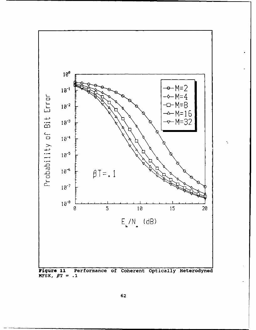
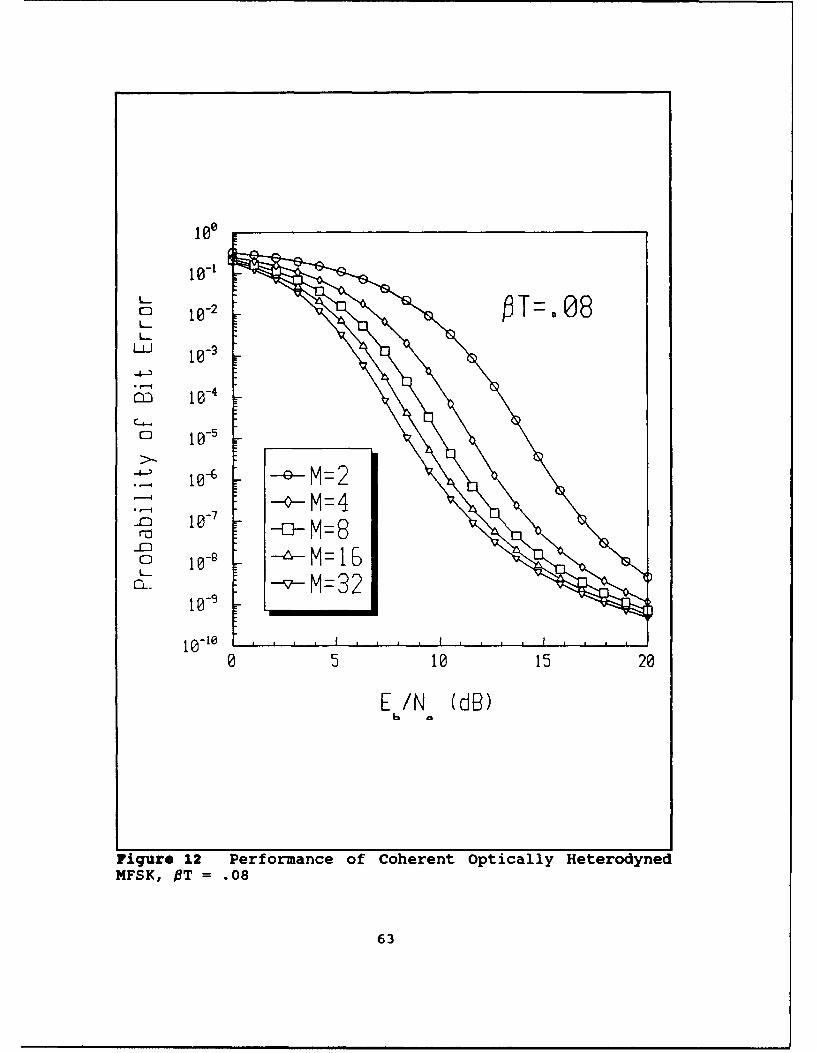
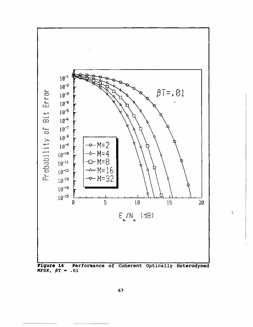
in Figure 11 through 16 for each PT previously observed. The
dominance of the laser phase noise on system performance is
observed for the lower symbol rates. For example, PT = 0.1,
the performance for each of the MFSK cases approaches an
56
Page 64
10-2 M=2
0 10-1
10-
0 10 -92
5 OT=00
E10N(dB
Figur 6 t Per orm nc of C h r n O t c l y He e y e
MFK H T= 24
ro 1057
Page 65
10-I
10-2
4) 10--46
M 10--
10-
10-1
0 5 10 15 20
E /N (dB)
Figure 7 Performance of Coherent Optically HeterodynedMFSK, M 4
58
Page 66
10-1
10-20 10-M
10--
-k 10-"
o - 10-
CO- 1W'4
.OIT=. 08t *..
1o- 05.. 1 O/T=. 04\
E /N (dB)6
Figure a Performance of Coherent optically HeterodynedMFSK, M = 8
59
Page 67
10-1-2
0~ 10-1 M=6L. 10- 1
..+._ 10-s 1-,--I
co 10_9--6-
- 10-
,5010- 5
+b a
Fiur 9@t Pefrac fChrn pial eeoye
-.0 -- vX- T-0
MF-, H =-16
01
to-t,5
05 10 15 20
E /N (dB)
IFiqr* 9 Performance of Coherent Optically HeterodynedMFSK, M = 16
60
Page 68
10-20- M=32L- 10-4L.
-4-) iO-1-
i0-5 1 1C-. 10-7
0. e -- ETd. 1S 10-1 -o / T = 08
Fge10 P Oa od= o-:' --o-/T=. 04lo1 -12-0 -- T- 0 2io-13 -- O-/T=. 0 1i0-14
0 5 10 15 20
E /N (dB)6
Figre 10 Performance of Coherent Optically Heterodyned
MFSK, M = 32
61
Page 69
L1
-4
4->
1 0-10152
n 10-6
6
Page 70
loll
10-1
4-D-
-0-4
io-'-M=
0 10152
0FK MT 1 .0
6
Page 71
10-
10-600
S10-1 -o- M=4
0 5= 10152
EIN (dB)
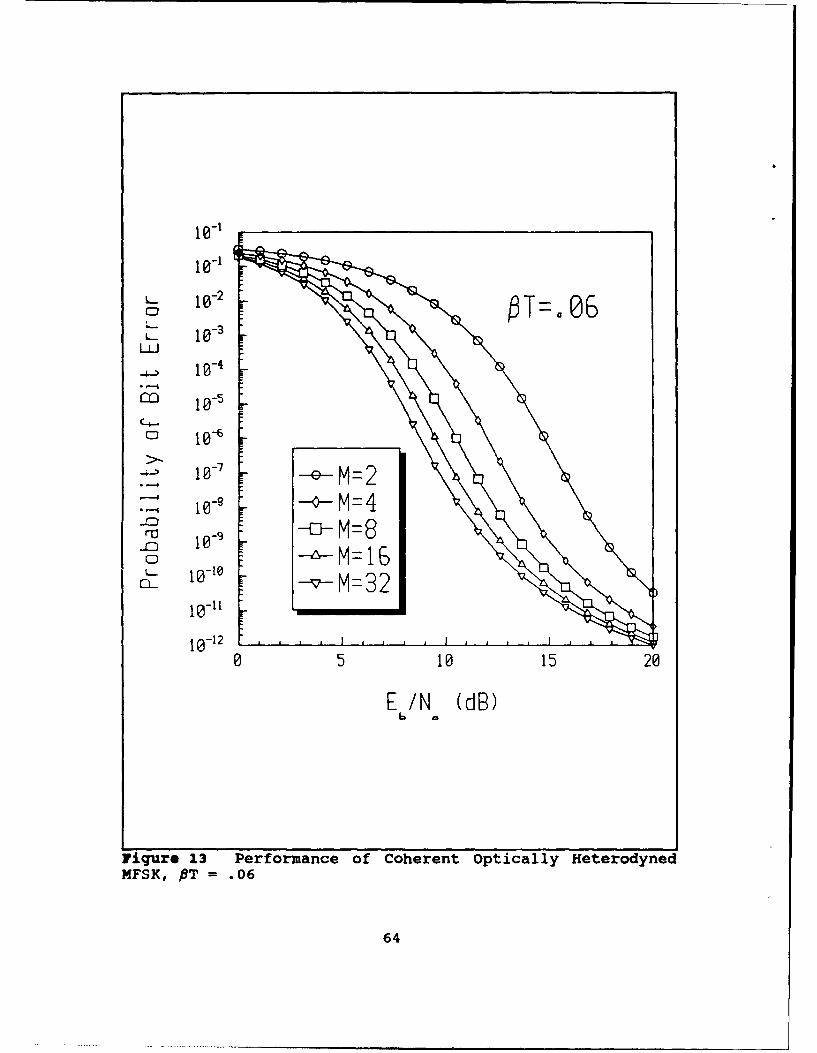
Figure 1.3 Performance of Coherent Optically HeterodynedMFSK, PT =.06
64
Page 72
to-,
10-2
LL_ 1 -
10.5
C-#--. t
0 5 10-552
-D
F0S10 MT = 40
o 10-11 =6
>.) io- 3 M.
-io -1 -4- -
10-15
0 5 10 15 20
E /N (dB)
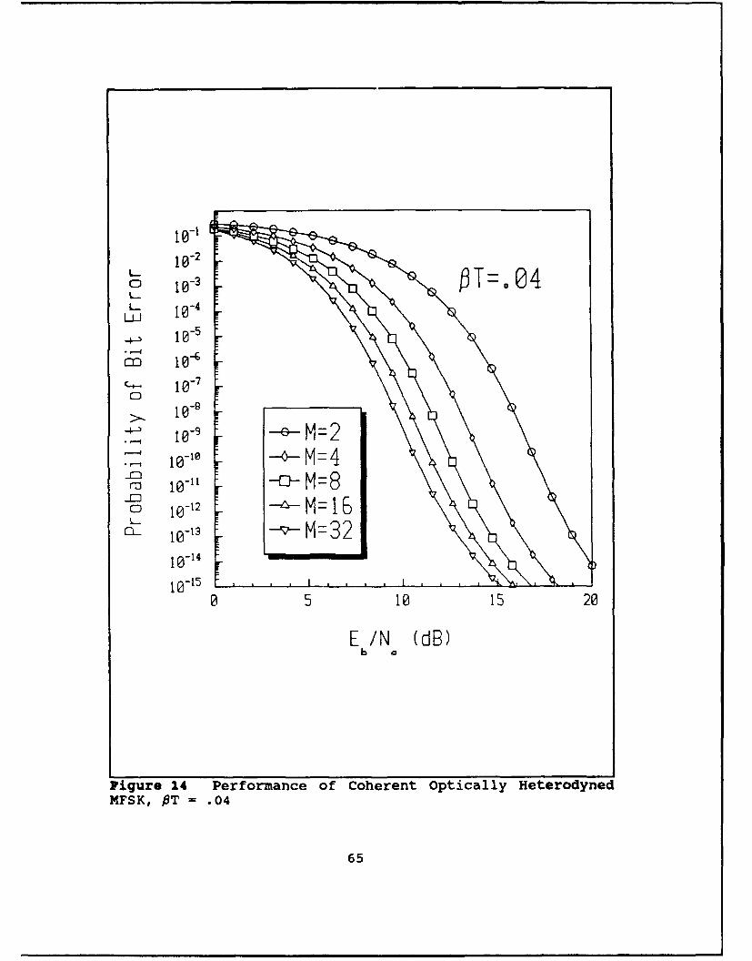
Figure 14 Performance of Coherent Optically HeterodynedMFSK, PT = .04
65
Page 73
i0-1
0f 10-3
10-1C- 051 52
to"
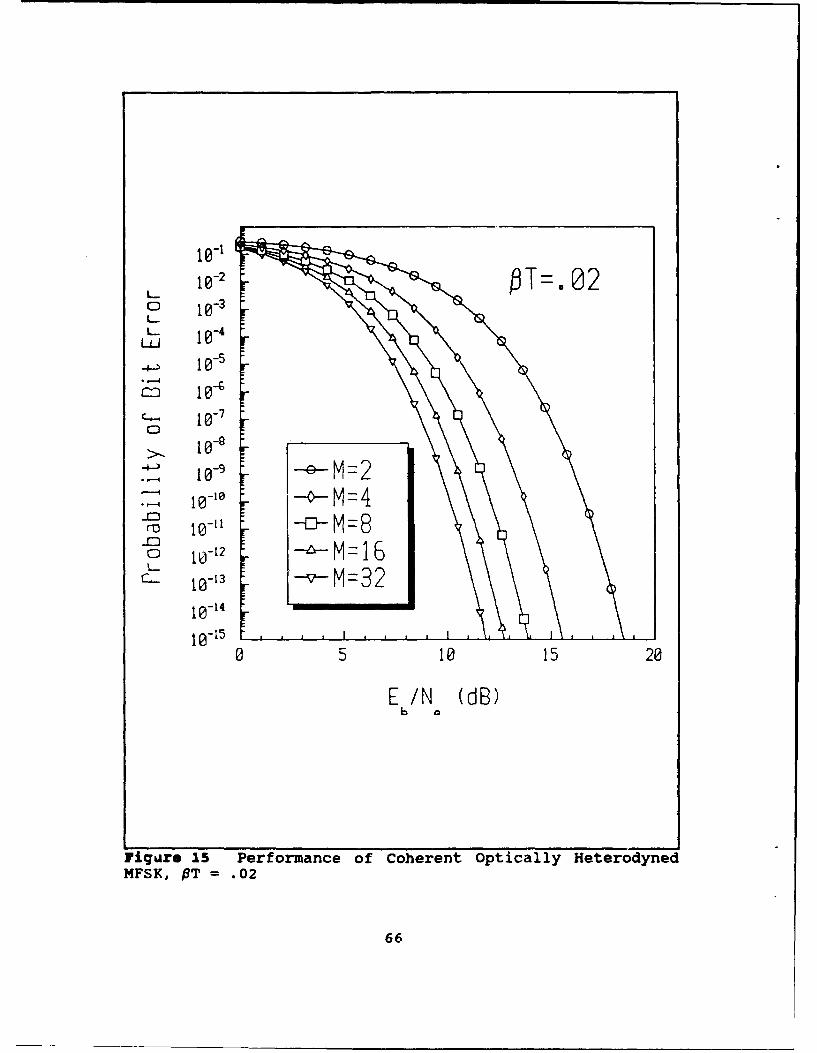
MF 102 MT 1 .
6
Page 74
10-1
10- 2
LLJ
m 10-'
C-+- 1 -0
C-I
0 5 10 15 20
E /N (18B)b o
Figure 16 Performance of Coherent Optically HeterodynedMFSK, PT = .01
67
Page 75
asymptotic limit as Eb/No increases. The performance does not
continue to improve as EWN increases or as M increases when
the laser phase noise is significant. This is contrary to
what is observed when laser phase noise is not present. As
another example, when PT = 0.04, a symbol rate twenty-five
times greater than the laser linewidth, the performance of
each of the MFSK cases is within one dB of the case when no
laser phase noise exists. These conclusions apply to the
range of probability of bit errors that are of concern for
practical communication systems, 10.9 to 10-6.
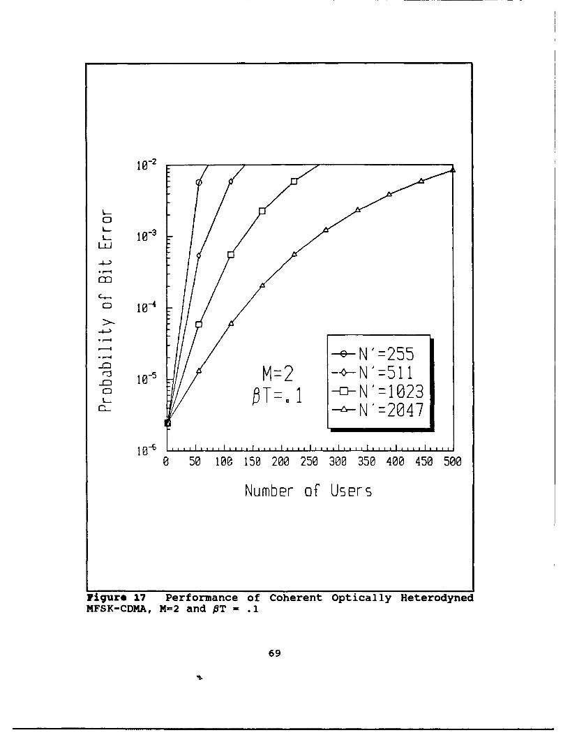
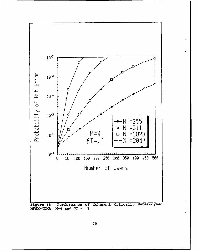
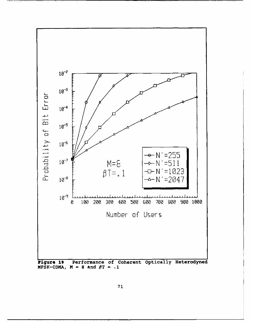
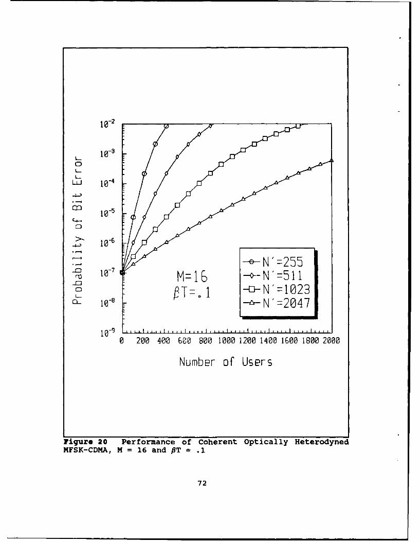
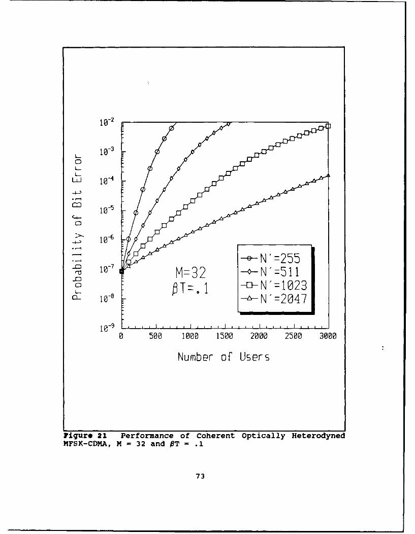
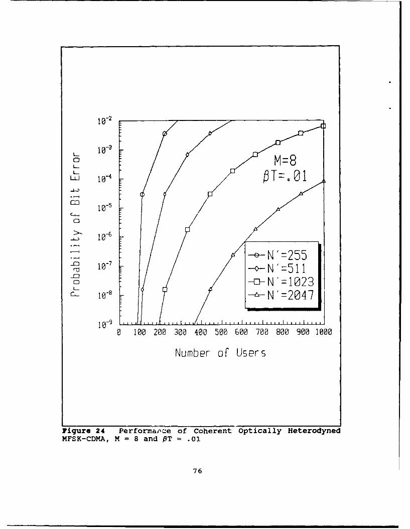
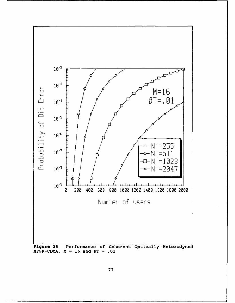
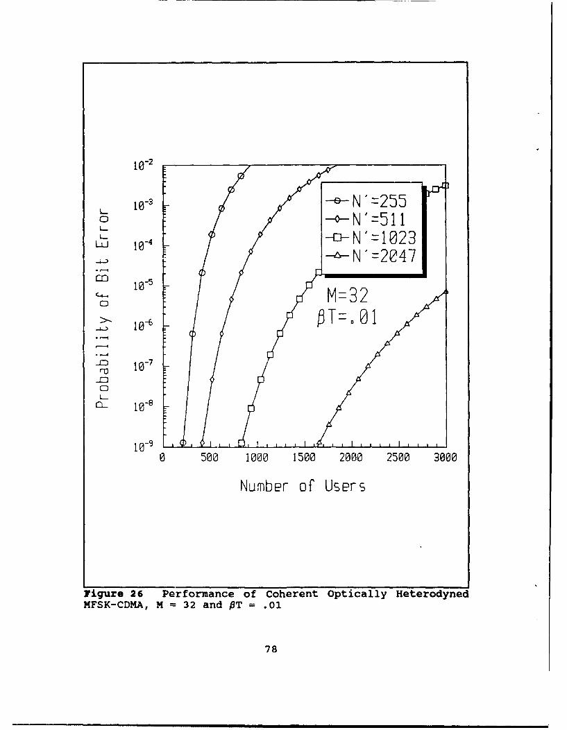
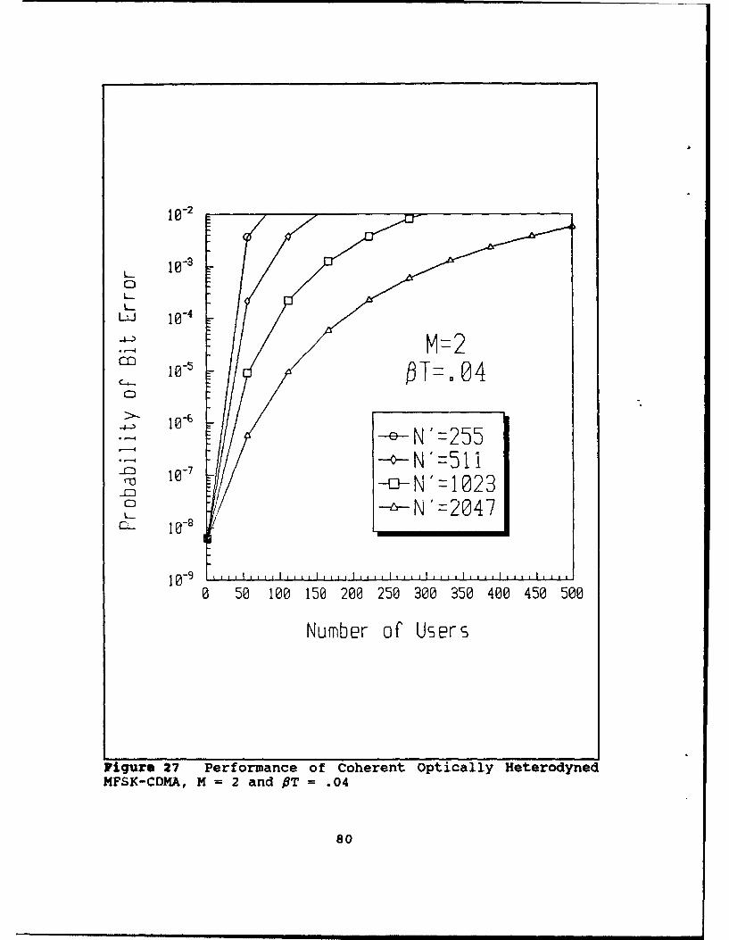
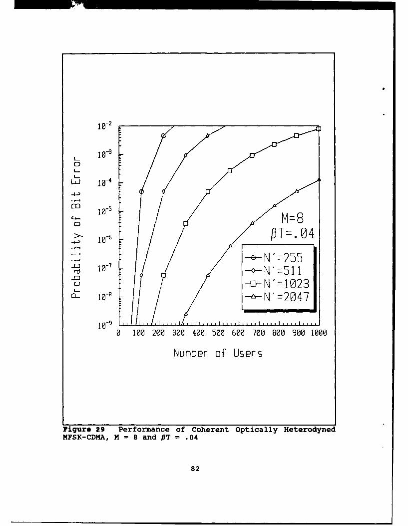
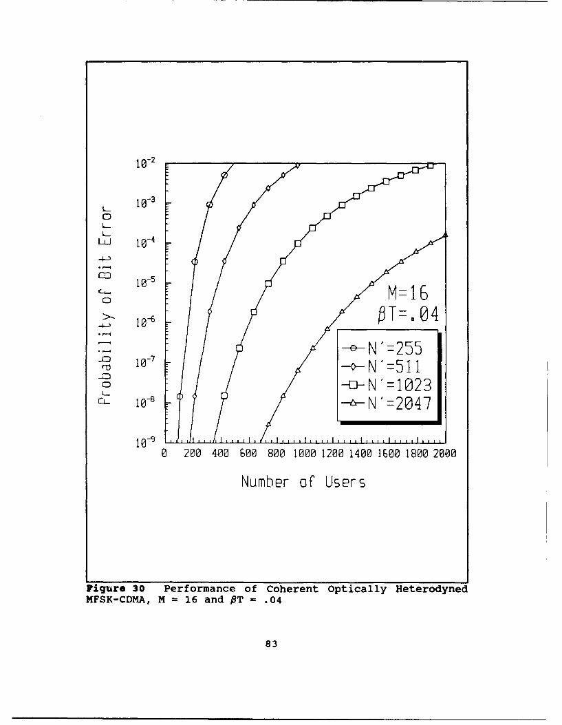
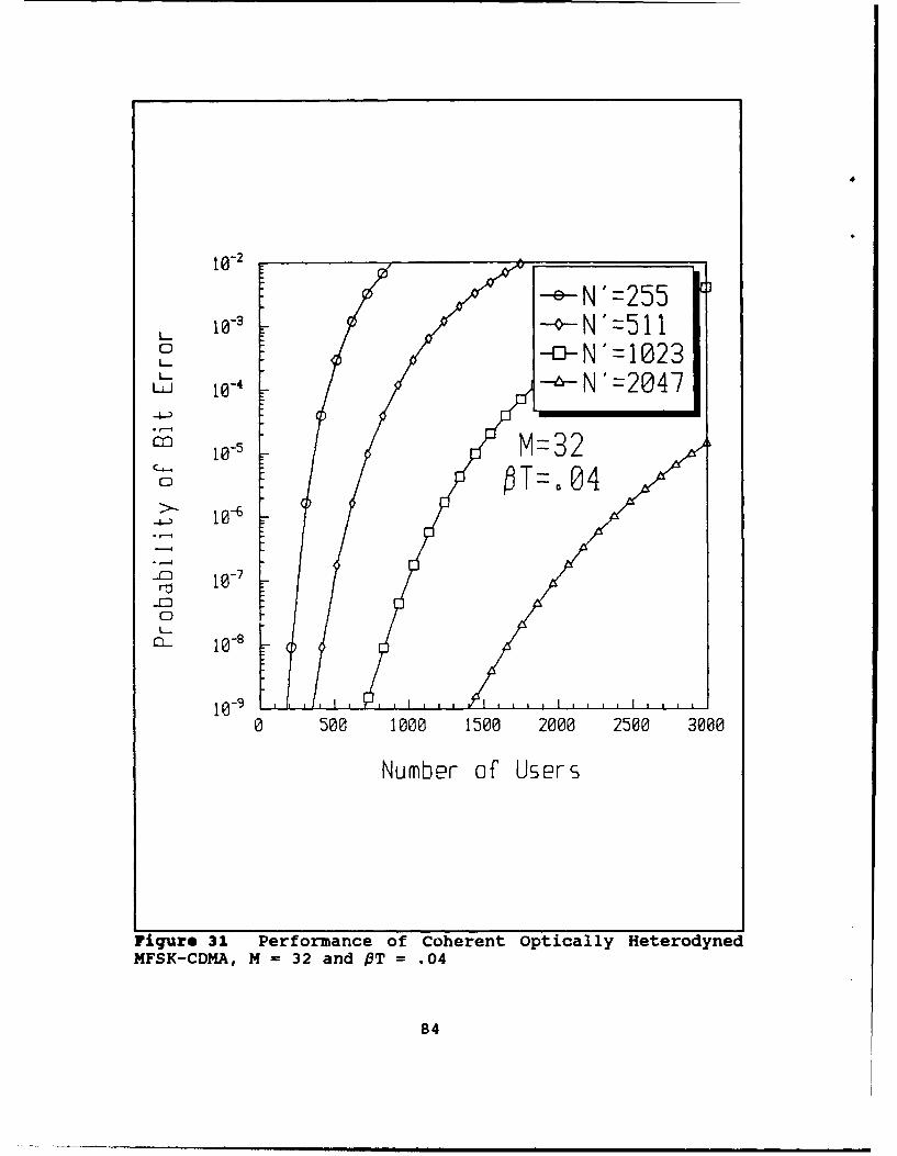
B. MFSK-CDHA
The probability of bit error for MFSK-CDMA is expressed in
terms of the number of users and the symbol rate linewidth
product. The MFSK-CDMA analysis is performed by using the
noise term, Equation (50), in Equation (43). In Figures 17
through 21 the performance is observed for PT = 0.1, when the
symbol rate is ten times the linewidth, for various values of
M. Few users can be added to the system since the performance
is poor even for a single user. This is expected since the
laser phase noise dominates system performance for the lower
symbol rates as was previously discussed. Increasing the
value of M has little impact on the number of users that can
be added to the system. Once again, this is consistent
considering that the laser phase noise is dominant. The
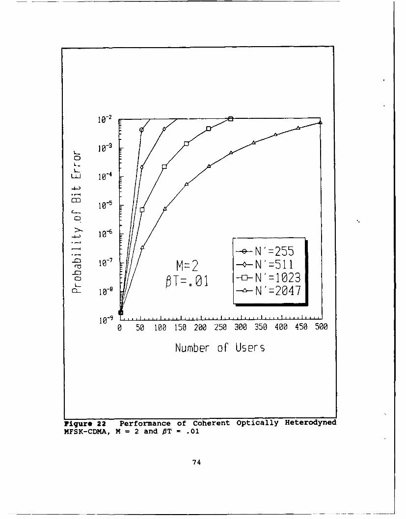
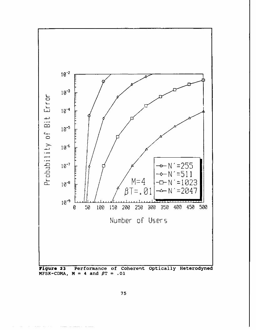
opposite is observed in Figures 22 through 26. For this
68
Page 76
10- 2
0L... 10 -3
- 10-1
o Z
0 ~-e-N'=125
-N'=2047
10-60 50 100 150 200 250 300 350 400 450 500
Number of Users
Figure 17 Performance of Coherent Optically HeterodynedMFSK-CDHA, M=2 and PT = .1
69
Page 77
10-2
0 _. 1 0 -3 .
LJ
10-5
-e-N'=255r -4-N'=511
10 M=4023CTL. N '=2047
10-7 ...0 50 100 150 200 250 300 350 400 450 500
Number of Users
Figure 18 Performance of Coherent Optically HeterodynedMFSK-CDMA, M=4 and PT = .1
70
Page 78
10- 2
10- 30
L- 10 - 1
10-50
10--
e N255M= - N'=51 I
.El T o1 -0- N'=-1023Cl- 10-11 --.,n-N "=2047
0 100 200 300 400 500 600 700 800 900 1000
Number of Users
Figure ig Performance of Coherent Optically eterodynedMFSK-CDMA, M = 8 and PT = .1
71
Page 79
1 e-2
10-
100C-4
10-
C
10-6__ _ _ _ _
-ED 10- 7 1 -N'=511
0 200 400 600 800 1000 1200 1400 1600 1800 2000
Number of Users
FiqUre 20 Performance of Coherent Optically HeterodynedMFSK-CDMA, M = 16 and OT = .1
72
Page 80
10-2
-4-,
C4-
0 0-
0 --o -N ' 1 0 2 3Cl- 10-11N'=2047
0 50 1000 1500 2000 2500 3000
Number of Users
Figure 21 Performance of Coherent Optically HeterodynedMFSK-CDMA, M = 32 and PT = .1
73
Page 81
10-2B
10-0
10-6
N'25-M1 -
bT 0 1 No-=>1023
0 50 100 150 200 250 300 350 400 450 500
Number of Users
Fiqure 22 Performance of Coherent Optically Hetero~dynedMFSK-CDMA, M = 2 and PT = .01
74
Page 82
102
10-5
10-
Mz4 -iM=4N'= 1023~T~O -~-N'=2047
0 50 100 150 200 250 300 350 400 450 500
Number of Users
Figure 23 Performance of Coherent Optically HeterodynedMFSK-CDMA, M =4 and PT = .01
75
Page 83
10-2
10@-3 ~
0 M=
III 10- fT O1
i. 10-
10-6-
1079N-5ro '= 1
m -
0 100 200 300 400 500 600 700 800 900 1000
Number of Users
Figure 24 Performapce of Coherent Optically HeterodynedMFSK-CDMA, M = 8 and PT = .01
76
Page 84
10-2
10-30 M 16LLJ i@-4 T- 01
02 10-5
4-,
-- N'=255---N =511
CD --o-N'=1023-10-1 --N '=2047
0 200 400 600 800 1000 1200 1400 1600 1800 2000
Number of Users
Figure 25 Performance of Coherent Optically HeterodynedMFSK-CDMA, M = 16 and PT = .01
77
Page 85
10-2
10 l-3 -- N '= 2 5 50 -0 N'=511I
-I
10-
o
10-8
C
1..
10 -9 1 I 1_ 1 1 1 1
0 500 1000 1500 2000 2500 3000
Number of Users
Figure 26 Performance of Coherent Optically HeterodynedMFSK-CDMA, M = 32 and PT = .01
78
Page 86
analysis the symbol rate is 100 times the linewidth, PT =
0.01. The number of users obviously increases from the PT =
0.1 case for the same value of M and a given probability of
bit error since the laser phase noise no longer has an impact
on the system performance. The system performance when PT =
0.01 is degraded only by the addition of more users to the
system. Since the maximum average bit energy is set to 16 dB
for all of the MFSK analyses, then the SNR is larger as M
increases resulting in a better system performance which
allows more users.
In either the PT = 0.1 or the PT = 0.01 cases, the number
of users increases for longer codelengths before a given
minimum performance level is reached. This is true for CDMA
systems in general. As the codelength is increased, the
amount of noise that a single interfering user contributes is
smaller if the amount of signal power received is normalized.
Therefore, more users can be added to the system before a
specific minimum performance level is attained.
For the single user MFSK, the system performance when PT
= 0.04 is degraded only slightly because of laser phase noise.
The MFSK-CDMA system performance for PT = 0.04 is shown in
Figures 27 through 31. As an example, the number of users
that can access the system for M = 4, codelength = 1023, and
a maximum probability of bit error of 10.6 increases from
approximately 40 users for PT = 0.1 to 130 users for PT =
0.04. This improvement requires only a symbol rate of twenty-
79
Page 87
10-2
L_.
w10- 1
m 10-5 01
1- -cN'=255-o-N'=5 iS-- N'-1023
S--- N '=2047CL. 10-__
0 50 100 150 200 250 300 350 400 450 500
Number of Users
liqure 27 Performance of Coherent Optically HeterodynedMFSK-CDMA, M = 2 and PT = .04
80
Page 88
10- 2
L.J 10-4
4-,
,-4
CD
10-
0 50= 1015 0 5 0 5 02535
Number of Users
Figure 28 Performance of Coherent Optically HeterodynedMFSK-CDMA, M = 4 and OT = .04
81
Page 89
10-2
27 10- 6 OT__ .__04
1W8 -~-N'=2557
10-90 100 200 300 400 500 600 700 800 900 1000
Number of Users
Figure 29 Performance of Coherent Optically HeterodynedMFSK-CDMA, M = 8 and OT = .04
82
Page 90
10-2
10-
wL 10- 4
1o 10-50
eN'=255ra ~N'=511I
CD -a-N'1023C- 8 10-1N'=2047
10- 90 200 400 600 800 1000 1200 1400 1600 1800 2000
Number of Users
Figure 30 Performance of Coherent Optically HeterodynedMFSK-CDMA, MH 16 and OT = .04
83
Page 91
11023
-4
MF1KCD-5 M=322n fT= 0
0 T-.84
Page 92
five times the laser linewidth. This can be compared to 140
users for PT = 0.01 which requires a symbol rate of 100 times
the laser linewidth.
C. Differential Phase-Shift Keying
The DPSK system analysis is performed by numerically
evaluating Equation (93). This is plotted in Figure 32. The
performance of the DPSK system shows the same trends as are
observed in the MFSK case. The 3 dB improvement of DPSK over
binary FSK is observed for the case when laser phase noise
becomes negligible, PT = 0.01, as expected. Once again, a bit
rate of twenty-five times the laser linewidth, PT = 0.04, is
sufficient to overcome the effects of laser phase noise for
the range of probability of bit error, 10,9 to 10.6, that are
of concern for practical digital communication systems.
D. DPSK-CDMA
The performance of the DPSK-CDMA system is found by using
the noise term of Equation (99) in the probability of bit
error expression, Equation (93), and numerically integrating.
The results are plotted in Figure 33 for PT = 0.1 and in
Figure 34 for PT = 0.01. The DPSK-CDMA results are consistent
with that observed for the MFSK-CDMA case. For relatively low
bit rates, PT = 0.1, few users can be added to the system
since the system performance is degraded laser phase noise.
For higher bit rates, OT = 0.01, then a larger number of users
85
Page 93
'0-1
10-2
w
-M- 10-
>C. 10-1
-c-1
0 5 10 15 20
E6 /N (dBP)
Figure 32 Coherent Optically Heterodyned DPSK Performance
86
Page 94
o0-
1i-5
UPSK -oN=1023IT0 -6-N=2047
0 50 100 150 200 250 300 350 400 450 500
Number of' Users
Figure 33 Performance of Coherent Optically HeterodynedDPSK, PT = 1
87
Page 95
10-2
_ 10 -100CD
10- 6
0
S 1 -~
-e-N=255.- 3 10 7- -- N-51 i
t--I N -- N1023
10 -1 1 , 1 1 l 1 1 1 1 , I i l 1 1
0 50 100 150 200 250 300 350 400 450 500
Number of Users
Figure 34 Performance of Coherent Optically HeterodynedDPSK, PT = .01
88
Page 96
can be added to the system. The effect of laser phase noise
no longer degrades the system performance. Just like the
MFSK-CDMA case, for high bit rates the system performance is
only affected by increasing the number of users. Whn
observing the single user DPSK system analysis, for PT = 0.04
the system performance is only slightly affected by laser
phase noise. The DPSK-CDMA system performance for PT = 0.04
is shown in Figure 35. An increase in the number of users
from approximately 50 users for PT = 0.1 to approximately 140
users for PT = 0.04 is observed assuming a maximum probability
of bit error of 10.6 and a codelength of 1023. Increasing the
bit rate another factor of four, PT = 0.01, yields 150 users,
an increase of only ten.
89
Page 97
10- 2
10-1
CD D S
-~N'=2557
0 50 100 150 200 250 300 350 400 450 500
Number of Users
Figure 3S Performance of Coherent Optically HeterodynedDPSK, OT = .04
90
Page 98
VI. CONCLUSIONS
This thesis investigates the system performance of two
coherent optically heterodyned multiple access communication
systems, MFSK-CDMA and DPSK-CDMA. The effect of laser phase
noise that is inherent in coherent optical communication
systems is analyzed for the single user communication system
as well as the multiple user system. The analysis of the
multiple access system helps to provide insight to the utility
of MFSX-CDMA and DPSK-CDMA as possible random access, high
data rate communication systems of the future.
The effect laser phase noise that exists in coherent
optical communication systems can be minimized by increasing
the data rate of the system. When the symbol rate for MFSK or
the bit rate for DPSK is raised to a value of twenty-five
times greater than the combined laser linewidth of the
transmit and local oscillator lasers, system performance is
only slightly affected by laser phase noise. This result
holds for the probability of bit error values between 10.9 and
10-6. System performance is virtually unaffected by laser
phase noise when the data rate is increased to 100 times the
laser linewidth.
The application of CDMA spread spectrum techniques to
coherent optically heterodyned communication systems better
utilizes the optical channel by allowing simultaneous
91
Page 99
asynchronous access by multiple users. This thesis has shown
that more users can be added to the multiple access system by
increasing the codelength or by reducing the effects of laser
phase noise by increasing the data rate. When the effect of
laser phase noise is reduced then the number of users can be
increased using a higher M for MFSK. All of these
improvements occur at the expense of increasing the amount of
bandwidth required. For an optical communication system,
limiting the required bandwidth is not an overriding design
consideration. As shown in Chapter V, a significant increase
in the number of users can be achieved if the data rate is
increased from ten times the laser linewidth to twenty-five
times the laser linewidth. Only a minimal increase in the
number of users will occur if the data rate is raised even
higher.
Future research is needed in the areas of coherent optical
communications and in the area of fiber optic CDMA
communication systems. This work involved optical
heterodyning and electronic demodulation of the received
signal. Research is ongoing in the areas of optical
demodulation [Ref. 1,3] and in the optical processing of CDMA
systems [Ref. 13]. An all optical system will improve system
performance due to the increased speed of optical processing
and wider possible bandwidths.
This thesis performed theoretical analyses of the coherent
optically heterodyned communication systems with MFSK-CDMA and
92
Page 100
DPSK-CDMA signalling. Simplifying assumptions are made to
ease the mathematical analysis. Some of the system
requirements, such as maintaining polarity and coherently
demodulating CDMA, are difficult to achieve which may affect
system performance. The best evaluation of the performance of
any system would be the actual construction and testing of the
system. This thesis indicates that such a system
configuration can improve the performance of future optical
communication systems.
93
Page 101
REFERENCES
1. Salz, J. "Coherent Lightwave Communications," AT&TTechnical Journal, Vol. 64, No. 10, pp. 2153-2207, December1985.
2. Vodhanel, R., "Optical Sources for Coherent Optical FiberCommunications," Proceedings of SPIE, Vol. 568, pp. 9-13,August 1985.
3. Okoshi, T. and Kikuchi, K., Coherent Optical FiberCommunications, Kluwer Academic Publishers, 1988.
4. Powers, J., "An Introduction to Fiber Optic Systems,"Class Notes from EC 3550, Naval Postgraduate School, Monterey,CA, September 1990.
5. Brain, M. and Lee, T., "Optical Receivers for LightwaveCommunication Systems," Journal of Lightwave Communications,Vol. LT-3, No. 6, pp. 1281-1300, December 1985.
6. Foschini, G., Greenstein, L. and Vannucci, G., "EnvelopeStatistics for Filtered Optical Signals Corrupted by PhaseNoise," IEEE Transactions on Communications, Vol. 37,No. 12,December 1989.
7. Geraniotis, E., "Performance of Noncoherent Direct-Sequence Spread-Spectrum Multiple-Access Communications,"Journal of Lightwave Technology, Vol. LT-3, No. 1, February1985.
8. Whalen, A., Detection of Signals in Noise, Academic Press,1971.
9. Foschini, G., Greenstein, L., Vannucci, G., "NoncoherentDetection of Coherent Lightwave Signals Corrupted by LaserPhase Noise," IEEE Transactions on Communications, Vol. 36,No. 3, pp. 306-314, March 1988.
10. Beyer, W., CRC Standard Mathematical Tables, CRC Press,Inc., 1981.
11. Sklar, B., Digital Communications, Prentice Hall, 1988.
12. Turin, G., "The Effects of Multipath and Fading on thePerformance of Direct-Sequence CDMA Systems," IEEE Journal on
94
Page 102
Selected Areas in Communications, Vol. SAC-2, No. 4, pp. 597-603, July 1984.
13. Prucnal, P., Santoro, M., Fan, T., "Spread Spectrum Fiber-Optic Network Using optical Processing," Journal of LightwaveTechnology, Vol. LT-4, No. 5, May 1986.
95
Page 103
INITIAL DISTRIBUTION LIST
1. Defense Technical Information Center 2Cameron StationAlexandria, VA 22304-6145
2. Library, Code 52 2Naval Postgraduate SchoolMonterey, CA 93943-5000
3. Chairman, Code EC 1Department of Electrical and Computer EngineeringNaval Postgraduate SchoolMonterey, CA 93943-5000
4. Professor R. C. Robertson, Code EC/Rc 5Department of Electrical and Computer EngineeringNaval Postgraduate SchoolMonterey, CA 93943-5000
5. Professor T. T. Ha, Code EC/Ha 1Department of Electrical and Computer EngineeringNaval Postgraduate SchoolMonterey, CA 93943-5000
6. LT David A. Jakubek, USN 2Code 80, SOAC Class 92030Box 700Groton, CT 06349-7000
7. LT Kent Varnum 1Naval Ordinance Missile Test StationWhite Sands Missile Range, NM 88002
96