AL/HR-TR-1993-0120 AD-A270 578 A A FULL-COLOR, HIGH-RESOLUTION LASER PROJECTOR R FOR A FLIGHT SIMULATOR VISUAL DISPLAY M S T Philipp W. Peppier R J. C. Gainer G 1993 L HUMAN RESOURCES DIRECTORATE AIRCREW TRAINING RESEARCH DIVISION A 6001 South Power Road, Building 558 B Mesa, AZ 85206-0904 0 R A August 1993 T Final Technical Report for Period January 1993-July 1993 0 R Approved for public release; distribution is unlimited. Y 93-23090 z> 111liiil lI3Billlll lll tI 3 1 0 1 2 4 7 [ininAIR FORCE MATERIEL COMMAND BROOKS AIR FORCE BASE, TEXAS ___________MW
Transcript
AL/HR-TR-1993-0120
AD-A270 578
A A FULL-COLOR, HIGH-RESOLUTION LASER PROJECTOR
R FOR A FLIGHT SIMULATOR VISUAL DISPLAY
MST Philipp W. Peppier
R J. C. Gainer
G 1993
L HUMAN RESOURCES DIRECTORATEAIRCREW TRAINING RESEARCH DIVISIONA 6001 South Power Road, Building 558
B Mesa, AZ 85206-0904
0RA August 1993
T Final Technical Report for Period January 1993-July 1993
0R Approved for public release; distribution is unlimited.Y
93-23090 z>111liiil lI3Billlll lll tI 3 1 0 1 2 4 7[ininAIR FORCE MATERIEL COMMAND
BROOKS AIR FORCE BASE, TEXAS ___________MW
NOTICES
This technical report Is published as received and has not been edited by thetechnical editing staff of the Armstrong Laboratory.
When Government drawings, specifications, or other data are used for arnypurpose other than In connection with a definitely Government-related procure-ment, the United States Government Incurs no responsibility or any obligationwhatsoever. The fact that the Government may have formulated or In any waysupplied the said drawings, specifications, or other data, is not to be regarded byimplication, or otherwise in any manner construed, as licensing the holder, or anyother person or corporation; or as conveying any rights or permission tomanufacture, use, or sell any patented invention that may in any way be relatedthereto.
The Office of Public Affairs has reviewed this report, and it is releasable to theNational Technical Information Service, where it will be available to the generalpublic, Including foreign nationals.
This report has been reviewed and is approved for publication.
PHILIPP W. PEPPLER DEE H. ANDREWSProject Scientist Technical Director
A A O CleUSAFhief, Airew Training Research Division
REPORT DOCUMENTATION PAGE Form Approved
I 0AoB No. 0704-0188Public reporting burden for this collection of tnfnrmation s estimated to average 1 hour per respDnrse. including the time for reviewing instructions, searching existing data sources.gathering and maintaining the data needed, and completing and reviewing the collection of information Send comments regarding this burden estimate or any other aspect of thiscollection of information, fncluding suggestions for reducing this burden to Washington Headquarters Services, Directorate for information Operations and Reports. 1215 JeffersonDavis Highway. Suite 1204. Arlington. VA 222024302. and to the Office of Management and Budget. Paperwork Reduction Project (0704-0158). Washington, DC 20503
1. AGENCY USE ONLY (Leave blank) 2. REPORT DATE 3. REPORT TYPE AND DATES COVERED
August 1993 Final January 1993 -July 19934. TITLE AND SUBTITLE S. FUNDING NUMBERS
A Full-Color, High-Resolution Laser Projector PE - 62205Ffor a Flight Simulator Visual Display PR - 11236. AUTHOR(S) TA - 05
WU- 01Philipp W. PepplerJ. C. Gainer7. PERFORMING ORGANIZATION NAME(S) AND ADDRESS(ES) 8. PERFORMING ORGANIZATIONArmstrong Laboratory (AFMC) REPORT NUMBERHuman Resources DirectorateAircrew Training Research Division6001 South Power Road, Building 558 AL/HR-TR-1993-0120Mesa, AZ 85206-09049. SPONSORING/MONITORING AGENCY NAME(S) AND ADDRESS(ES) 10. SPONSORING/MONITORING
AGENCY REPORT NUMBER
11. SUPPLEMENTARY NOTES
12a. DISTRIBUTION / AVAILABILITY STATEMENT 12b. DISTRIBUTION CODE
Approved for public release; distribution is unlimited.
13. ABSTRACT (Maximum 200 words)Laser projection is a promising approach to solving many of the shortcomings associated with current flight
simulator projection methods. The advantages of laser projection were investigated and are discussed. Thecharacteristics of light valve, cathode-ray tube (CRT), liquid crystal display (LCD), and laser projectors arecompared. It was found that laser projection offers many benefits over current projection technology. Laserprojection promises an increased color gamut, higher luminance, zero persistence, and increased line rate. Thetechnology required to develop an efficient, cost-effective laser projector was researched and is described.Recent advances in laser diodes, solid-state diodes, and other rapidly developing technologies and techniqiespromise new territory for laser projection. It is concluded that laser projection is a promising solution to theshortcomings of flight simulator visual displays and that the technology now exists to develop an efficient, costeffective laser projector.
14. SUBJECT TERMS Laser projectors Projectors 15. NUMBER OF PAGES
This investigation contributes to the development of cost-effective,high-fidelity, flight simulation visual display technology. For a pilot toperform air-to-air, air-to-ground, and terrain-following fighter aircraftmaneuvers in a flight simulator, it is important that the out-the-windowvisual provide bright, properly defined targets and scenery. Thisinvestigation addresses this critical requirement for development of acost-effective, high-fideJlty, visual display system.
Technology discussed in this report also addresses recentlegislation promoting dual-use technologies in the Department of Defense(DOD). This technology may lead to developments in future high definitiontelevision and other visual display applications. It also could promotesmall business innovation research (SBIR) and other cooperative effortsthat maximize benefits obtained through DOD research and developmentinvestments.
The authors wish to thank Dr. Celeste Howard and Dr. Julie Lindholmof the University of Dayton Research Institute, Mr. Gale Reining of MartinMarrietta Corporation, and Mr. Carl Cox of Lincoln Laser Company for theirdiscussions and assistance in preparing this report.
This work was conducted under Work Unit 1123-05-01, In-HouseResearch and Development Support. Work unit monitor was Mr. Burlin M.Griffin. Principal investigator was Mr. Philipp W. Peppier.
iv
A FULL-COLOR, HIGH-RESOLUTION LASER PROJECTOR
FOR A FLIGHT SIMULATOR VISUAL DISPLAY
INTRODUCTION
Flight simulator displays at Armstrong Laboratory have recently usedlight valve projectors, liquid crystal display (LCD) projectors, and highresolution cathode-ray tube (CRT) projectors to present the out-the-windowvisual scene. Relatively high-cost light valve projectors have been themainstay of flight simulator visual displays for years. LCD and CRT highresolution (1,026 x 1,026 line) projectors have led to less expensive flightsimulator displays, but other simulator components, such as computer imagegenerators and microcomputers, have matured at a much greater pace. As aconsequence, displays often limit simulation fidelity and make certaintraining tasks in a flight simulator difficult if not impossible. Introductionof an advanced projection system would certainly bring a welcome boost toflight simulator visual display c3pability.
Laser-based projection is a promising technology that may resolve manyof the problems associated with current projection methods. Laser light hasmany characteristics that make it an ideal light source for an advancedvisual projection system. Laser light is far more directional, powerful, and
coherent 1 than any other light source. Lasers produce an intense beam thatis very pure in color. Laser-produced red, green, and blue primarywavelengths plot on the boundary of the ICI (CIE) chromaticity diagram; a
characteristic that allows a very large gamut of colors. Unlike deformableoil films, phosphors, and LCDs, a laser has zero persistence. Moving imagesin a laser display will not smear or blur.
In recent years, foreign and domestic laser suppliers have aided thedevelopment of various laser-based projection devices. Federal Aviation
1Coherent light is light of a single frequency or color in which all
components are in step with each other.
1
Administration (FAA) and other military training programs have developedand used laser projection systems. The size and inefficiency of earlierlasers has kept laser projection from achieving widespread use, however,recent developments in laser technology promise new territory for laserprojection systems. Less expensive and more efficient lasers are rapidly
becoming available. Devices and techniques leading to new and improved
capabilities are continuously being developed.
Laser projection presents a promising approach to producing brighter,higher resolution, high-contrast, out-the-window scenes. Such a systemwould not only improve flight simulation and training, but it would also have
the potential to stimulate improvements in other display applications as
wel!.
WHY A LASER PROJECTOR?
Examining the characteristics of current technology will help tounderstand the benefits gained from a laser projector. Light valve, CRT, and
LCD projectors are capable devices that have been used in flight simulatorand other visual displays for years, yet, they have considerable
shortcomings. When the requirements for luminance, resolution, contrast,and saturated colors increase, the shortcomings of current technologybecome apparent. The characteristics of laser light make it an attractivesolution.
Color light valve, CRT, and LCD projectors use the additive combinationof red, green, and blue primary colors to produce their available colors. ACRT achieves the three primaries by exciting red, green, and/or bluephosphor dots placed on the display surface. In a CRT projection display, theimages from red, green, and blue monochrome CRTs are combined to create asingle full-color display. An LCD projector optically combines the outputfrom red, green, and blue LCD panels to produce color. A light valve extracts
the three primaries from a single xenon light source. As light passesthrough dichroic filters it is converted into green and magenta (red and blue)light. Not only does light valve, CRT, and LCD technology differ, but so dotheir color characteristics.
2
Figure 1 gives a representation of the differences in color
characteristics of a light valve, CRT, and laser projector. Since the colorgamut of any particular projection can be manipulated easily with filters,phosphors, etc., the color gamuts shown in Figure 1 should only be
considered as representative. How6v-r, as Figure 1 shows, the color gamutof a laser display is typically much larger. This maximizes the color spaceavailable for displaying highly saturated colors. The color gamut of aparticular laser display depends on the wavelengths of the lasers used in thesystem. But because laser primary colors are so pure, changing thewavelength just slides the triangle corners along the boundaries of the CIEdiagram (Jachimowicz, 1992).
0.8 Laser color gamut (Bentley and Ansley, 1992)
0.7 Talaria flight valve color gamut (Howard, 1989)
0.6 CRT color gamut (Jachimowicz, 1992)
0.5y
0.4
0.3
0.2 CIE 1931
0.1 The color gamut boundaries are representativeand may change with differing luminance levels
0.1 0.2 0.3 0.4 0.5 0.6 0.7 0.8
x
Figure 1Color Gamut of Laser Projection Display
Using Green at 514 nm, Red at 647 nm, and Blue at 488 nm
3
Pure colors from lasers also enable chroma multiplexing. Narrow bandrejection filters can be placed on the trainee's visor to prevent him/herfrom seeing another scene being projected on the same display by aprojector using different red, green, and blue laser wavelengths. Traineessuch as a pilot and weapon systems officer could train in the same displaywith different and noninterfering scenes (Bentley & Ansley, 1992). With theuse of filters that pass/reject different wavelengths placed over thegoggles, the pilot/weapon systems officer is able to see his own displaywithout interference from the other trainee.
Light valve projectors are favored for flight simulator domes and otherdisplays because of their ability to project scenes with both high luminanceand high resolution. Light valve projectors output around 2000 lumens. Yet,recent research has shown that luminance levels in the limited field of view(LFOV), 24-ft diameter dome at Armstrong Laboratory's Aircrew TrainingResearch Division, which use Talaria light valve projectors, is more likemoonlight than daylight, no matter what type of scene is being presented(Howard, 1989). Light losses in the LFOV display are certainly acontributing factor. However, if a display such as the LFOV dome is to beconsidered high fidelity, a projector with much greater luminance output isrequired. Other domes are known to exhibit even greater attenuation. Inaddition, as the xenon arc tube source in a light valve projector undergoesaging, the luminance output continually declines. Luminance levels fromcurrent light valve technology may be the highest available, but they fallshort of providing the luminance levels required for many visual displaysystems. Their relative high cost make them even less desirable.
CRT and LCD projectors are finding favor in many of the new low-costvisual displays. Luminance has improved while cost has declined. CRTprojectors typically output between 300 and 1500 lumens, depending on theperformance and cost of the system. However, major increases in theluminance output of a CRT projector may be difficult to achieve. Luminancelevels from a CRT are limited by its inverse relationship to resolution. Toincrease the luminance of a CRT, more electrons are required, resulting in alarger electron beam that lowers the resolution of the CRT. LCD projectorshave less luminance than a light valve or CRT. Recent models claim outputs
4
between 300 and 1,000 lumens. The development in this area has beensubstantial and is still very competitive. However, it remains questionablewhether CRT and LCD projector technology will ever be capable of providingthe luminance required for many flight simulator visual displays.
Light emitted by a laser is coherent in nature and therefore much moredirectional or concentrated than the noncoherent light sources used in lightvalve, CRT, LCD, and other displays. An obvious benefit of this is the abilityto obtain higher luminance. Luminance of a laser display is dependent uponthe power of the laser(s) used and the light throughput of the displaysystem. As laser technology improves so will the luminance levels of laserprojectors. In general, the luminance of a laser display would be orders ofmagnitude greater than systems using noncoherent Fght sources.
The coherency of laser light provides other benefits as well. Because ofits coherent nature, laser light can be focused to a very small spot -- acharacteristic that would support higher line rates. Laser light can befocused to such a small spot, that de-focusing is often required. Laser lightcan also be collimated so the distance to the screen does not affect focus --
a characteristic that would be useful in many applications.
A current technology projector is considered high resolution if itprojects a 1,026 x 1,026 line rate. Referring to these projectors as highresolution may be misleading. Much higher line rates would be extremelyuseful in a flight simulator. Higher line rates would increase the linedensity2 and improve the visual acuity of the display. With currentprojection methods, the pilot in a simulator often spots a long-distancetarget first by the halo rather than distinguishing the target itself. Thisobviously reduces realism. Image generators can be procured that output
2Line density is the number of lines per unit of space. With all othervariables the same, a 2,000 line projected image would have twice the linedensity as a 1,000 line projected image. An image with higher line densitywould have increased definition.
5
images with line rates exceeding 1,026 lines, however, there is no way toproject it. Improving the line density of the display by adding more channelsof imagery would be co'Oly and just disguise the problem. Developing aprojection system wit'- much higher line rates than current technology isthe key. Laser projection may be the answer.
The line rate of a laser projector is governed by how the laser beam is
deflected. There are various ways of deflecting the laser beam in a laserprojector. Laser beam deflectors will be discussed in a later section. But it
appears that the technology exists to develop a laser projection system thatwould project a 5,000 x 5,000 line image. This would be a major advantage.
Higher line density could be obtained with less channels of imagery, butmore important, the capability would exist to present a visual scene that
would give simulator pilots the ability to identify air and surface targets
and their attitude with similar fidelity and realism as in the aircraft.
Night vision goggle (NVG) training has taken on greater importance inrecent years. Because visual acuity is so much better at night when wearingNVGs, everyone tends to think they can see better than they really can.
Under certain circumstances this can lead to dangerous situations. Beingable to train with NVGs in a simulator under realistic conditions would behighly desirable. NVGs produce an image by amplifying low-level light andnear-infrared (IR) energy that is reflected/radiated from objects (See Fig.
2). A laser projector with near infrared capability would projectwavelengths from visible through mid-infrared exciting the full lightspectrum of the NVGs. It is understood that NVG simulations are affected byvarious technologies other than the display system. Yet, it seems safe to
say that a laser projector would bolster an NVG training system and at least
serve as a competent component of such a system.
A characteristic found in many displays using current projection
technology is persistence. Phobphors, oil films, and LCDs all have decaytimes and therefore produce persistence. Because of the way LCD projectorsobtain their brightness, they exhibit the most persistence. Unlike all ofthese, laser displays have zero persistence. Moving images in a laserdisplay will not smear, blur, or leave a trail. Zero persistence provides
6
other benefits as well. Switching between images or projector boundarieswould occur very rapidly. A projector with zero persistence is ideal forhighly dynamic visual displays such as head- and/or eye-tracked display
systems.GEN 10 NVG(CATSEYES. ANVLS)
O00NORMAL. NIGHT SKY
EHLJMA RADIATION
ao
RELATIERESPONSE(PERCENT4
40
400mm SOD~rn BOOM lOOrnm 1200nm
WAVELENGTH
k1V VSIBLENEAR' ~ LIGHT INFRAREI)
Figure 2Night Vision Goggle Light Characteristics
Laser projection offers many benefits and advantages over currentprojection technology. Benefits include increased color gamut, higherluminance, zero persistence, and increased line rate. All of which, wouldsignificantly improve display technology and lead to brighter, highercontrast, more realistic flight simulator visual displays. There have beenmajor advances in CRT and LCD projection technology in recent years. Butcompared to the advantages that could be obtained from a laser basedprojection system, current technology is clearly limited. Laser projection
offers a level in display technology that is simply not attainable from
current projection methods.
7
CURRENT LASER PROJECTION TECHNOLOGY
The word laser is an acronym derived from "light amplification by
stimulated emission of radiation." Einstein recognized the existence ofstimulated emission in 1917. It was not until the 1950s that ways werefound to use it in devices. Several U.S. and Soviet physicists proposedrelated ideas. The first laser, constructed by the U.S. scientist T.H. Maimanin 1960, used a rod of ruby. Since then many types of lasers have been built
and are available for a wide range of application. They vary in size and
power requirements depending on their use.
In 1988 the McTavish Company of England with assistance from LincolnLaser Company of Phoenix, Arizona developed a laser projection system forlarge hotels in Europe. This system uses a five watt Ar-Kr laser to project
a 12-ft x 6-ft scene from 20 ft away in the standard European format of625 lines at 50 Hz. An Ar-Kr laser emits light at two wavelengths. One at
450 nm (blue) and the other at 670 nm (red). Green is produced by a dyelaser. At that time, dye lasers had only 13% power output efficiency. The
other 87% of the power was radiated away in the form of heat. Because ofthis and other inefficiencies, a water cooling system was required thatmade this innovative projector overly large and bulky. Fortunately, recent
developments in lasers should alleviate the inefficiencies and decrease the
energy, cooling, and size required for a laser projector.
For some time, flight simulators have used laser projection systems toproject targets onto a scene. A system developed for the FAA's air traffic
control trainer uses twelve small lasers to project twelve moving targetsonto a wide angle visual background of an airport. Laser target projectors
continuously draw the target as the projector is moved and focusedappropriately for each target's location in the scene. Some are capable of
using television raster or calligraphic scanning to produce effects such asafterburners, missile launch flash, infrared decoys, and navigation lights.These projectors are useful with systems where the background does notmove or change rapidly. When used properly, these projectors can be very
8
effective. Similar projectors generate the colorful laser light shows seenat many entertainment events.
Hughes Aircraft Company has developed a laser projector that displaystwo full-color targets and one monochrome target, and provides non-interfering night vision goggle training for both the pilot and weaponsystems officer. This system generates colors with an Argon laser for blueand green and a dye laser for red. A near-IR laser is used to generate IRimages. A polygon mirror provides a scanning mirror surface that generatesthe horizontal sweep for the display. One polygon mirror provides threeindependent horizontal scans. Each horizontal scan is 960 pixels wide. A
galvanometer and associated mirror provide the vertical sweep for thedisplay. There are 875 TV lines. During night vision goggle training, thepilot and weapon systems officer train in the same dome wearing goggles.Near IR lasers operating at different wavelengths provide two independentundistorted images. With the use of filters that pass/reject differentwavelengths placed over the goggles, the pilot and weapon systems officerare able to see their own display without interference from the othertrainee. A 40-degree target size, combined with headtracking, allows thepilot/weapon systems officer to utilize night vision goggles at full dynamicrange and be safely exposed to the effects of blooming and automatic gaincontrol (Bentley & Ansley, 1992).
Volumetric 360-degree displays with helical and flat screens are usingHeNe and other lasers to present a real-time, 3-D image. Volumetricdisplays consist of various shapes of screens that are continucusly moved orrotated. An image is projected onto the continuously moving screen. As the
screen moves, the image is changed to accommodate the new spatialrelationships. Over one period the image seems to occupy the same space asthe moving screen (See Fig. 3). In this display, a radial scanner consistingof two mirrors fixed to a balanced rotating arm is coupled to the screen andspins in unison with it. The HeNe laser beam containing the imageinformation travels along the rotation axis, is reflected from the firstmirror to the second mirror, and then reaches the screen (Bains, 1993). An
9
3-D image 41 sm_ Rotating diffusion-.. --- screen
Addressed image point
Laser beam -•
•, Image information sourceComputer/HeNe laser
Figure 3Schematic of a Volumetric 360-Degree Display
image that can be seen through 360-degrees is produced. Some volumetricdisplays utilize a fixed scanner.
The Naval Training Systems Center (NTSC) in Orlando, Florida has beenactively developing laser based projection systems since the early 1980s.They have demonstrated that a laser projector can have greater resolutionand higher contrast than existing systems. NTSC has built and validated alow-cost, low-power laser television using the U.S. standard format of 525lines at 60 Hz. They are also developing a helmet-mounted, head-tracked
10
laser projector for projecting a full-color scene onto the surface of a dome.The system will display 1,000 lines and they expect a contrast ratio of 30:1.Colors are generated with an Argon laser and a dye laser.
These systems are interesting and give a sense of what could beaccomplished with an advanced laser projection system. Displays wouldpresent high-contrast, true-color day and night presentations. Along withthe many benefits associated with lasers, the same system could present animage in the IR spectrum for night vision goggle training. If noninterferingdisplays for a pilot/weapon systems officer is required, that could be doneas well.
The difficulty will be in developing a system that is efficient andportable. Luckily, laser technology and techniques are advancing at a greatpace. Recent advances in laser diodes, solid-state lasers, tunable lasers,and techniques such as solid-state diode pumping, optical combining of laserdiode outputs, and frequency doubling have matured to where an efficientand portable laser display seems attainable. The time has come to take thenext step. The question is: Can we do it?
CAN WE DO IT?
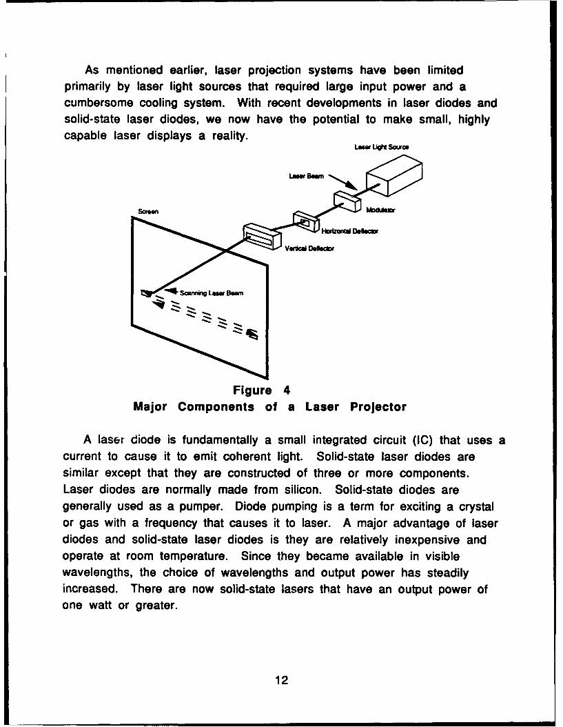
Raster laser projection systems utilize a scanning laser beam thatoperates in a similar manner as the electron beam of a CRT. Unlike a CRT,the screen does not luminesce; instead laser light is diffused onto a screen.A laser projector consists of several components (See Fig. 4). Componentsinclude: the laser light sources, modulators that encode the laser beam withintensity variations corresponding to the video information, and deflectorsthat provide horizontal and vertical scan of the laser beam. Full color laserdisplays use separate laser wavelengths for each primary color. Eachprimary is properly encoded by its modulator, and then combined with theother primaries for presentation. The horizontal, and vertical deflectorsthen place the laser beam at the proper location on the display. Imagesrequiring near infrared laser wavelengths are presented in a similar manner.
11
As mentioned earlier, laser projection systems have been limitedprimarily by laser light sources that required large input power and acumbersome cooling system. With recent developments in laser diodes andsolid-state laser diodes, we now have the potential to make small, highlycapable laser displays a reality.
Um ULt4 Soafos
Figure 4Major Components of a Laser Projector
A laser diode is fundamentally a small integrated circuit (IC) that uses acurrent to cause it to emit coherent light. Solid-state laser diodes aresimilar except that they are constructed of three or more components.Laser diodes are normally made from silicon. Solid-state diodes aregenerally used as a pumper. Diode pumping is a term for exciting a crystalor gas with a frequency that causes it to laser. A major advantage of laserdiodes and solid-state laser diodes is they are relatively inexpensive andoperate at room temperature. Since they became available in visiblewavelengths, the choice of wavelengths and output power has steadilyincreased. There are now solid-state lasers that have an output power ofone watt or greater.
12
Estimates predict that 1.47 watts (1,000 lumens) per primary would berequired at the screen for a high luminance (3,000 total lumens for day)laser display. Attenuation of the beam caused by optics in the displaysystem using a laser projector would require even greater power. Assumingapproximately .25 losses, a laser primary of 2 watts should be sufficient.Laser diodes and solid-state laser diodes with this energy may be developedin the near future but are not currently commercially available. To reachthe required power, some type of light amplification would have to beutilized until small and efficient lasers producing the required energy aredeveloped. Light amplification is a technique that is also being rapidlydeveloped.
A light amplification method showing promise is optical combining ofmultiple laser diodes. This technique increases the intensity of the outputbeam without altering the wavelength.
A modulator, synchronized with the laser beam deflectors, encodes thelaser beam with video information. Image information feeds into themodulator where the intensity of the laser beam is electronicallycontrolled. There are various ways of doing this. Electro-optic, acousto-optic, and deformable mirror modulators are the most common. Modulatorsfor 1,000- and 2,000-line scenes have been demonstrated -- 5000-linemodulators should be achievable. Each source (primary) would require amodulator. Laser beams 'ro.Pi the three modulators (representing the threeprimaries) are then optically combined before reaching the horizontal andvertical deflectors.
There are various methods of deflecting a laser beam in the horizontaland vertical axes. Deflection techniques include acolJsto-optic deflectionand mechanical mirror deflection, which includes rotating polygon scanners,galvanometer mirrors, and hologon deflection.
Rotating polygon scanners with mirror facets are used when repetitivescan at a fixed rate is desired. A motor assembly rotates the polygon whilethe laser beam reflects off the mirrored facets (See Fig. 5). These motorassemblies operate at very high speeds. Turbine driven polygon motor
13
assemblies are available that operate at 1.2 million revolutions per minute(RPM). Polygon scan mirrors can be fabricated to specification. As thepolygon rotates, the angle of incidence of the laser beam is changed, whichin turn changes the angle of deflection, and the laser beam traces out oneline for each facet. The polygon scanner is commonly used in laser rasterprojection displays to provide horizontal deflection.
Polygon deflection rates depend on the RPM of the polygon and thenumber of facets on the polygon. To increase the number of scan lines,either the number of facets, the polygon rotational speed, or both can beincreased.
Galvanometer deflectors are widely used as the vertical deflector inraster laser projection displays. A galvanometer provides single axis
14
rotation of a mirror, which in turn deflects the laser beam. Galvanometers
capable of deflecting a 5,000-line scene at 60 Hz are available.
Acousto-optic deflectors work in a similar manner as the acousto-optic
modulator. The difference is that acousto-optic deflectors vary acoustic
drive frequency to deflect the beam where the acousto-optic modulator
varies acoustic drive amplitude to modulate the beam. Acousto-optic
deflection is commonly used for horizontal deflection of a raster laser
display; however, this technique could be used for vertical deflection as
well.
Laser displays are not without some problems. One of them is speckle.
Speckle is a phenomena unique to laser-based displays. Speckle is the
sparkling/granularity effect visible in laser images which comes from
interference of the coherent laser beam with itself after passing through orreflecting off a diffuse screen. Speckle is present in most laser displays.
It is noticed less at lower luminance and can become brilliant at higher
luminances. Speckle removal techniques are available. Speckle can beremoved by either removing the coherency of the light or by overlaying many
different speckle patterns in space so they average out to be a smooth image
(Welford and Winston, I1389).
The technology to construct a full-color, high-resolution laser projectoris now becoming available. With the advent of laser diodes and solid-state
lasers, and the availability of acousto-optic modulators, deflectors, and
high-speed polygon mirror scanners, cost-effective laser projection can be
attained. These new technologies and techniques will surely reduce thepower and cooling requirements that have stymied laser projection in the
past. Companies such as Lincoln Laser of Phoenix, Arizona have been
developing and constructing scanners, galvanometers, and laser projection
devices since 1974. It is obvious that the technology and techniques are
available to make a major step up in flight simulation visual display
capability. Some development may be required to do so, but the major
pieces appear to be in place. Can we do it? Definitely!
15
Conclusions
Previous laser displays have been plagued by inefficiencies that requiredcumbersome power and cooling requirements. This has limited theirsuccess. New and rapidly advancing technologies and techniques promise torelieve many of the difficulties associated with previous laser projectionsystems. Efficient, low-cost, room temperature laser light sources arereadily available. High-speed scanners and modulators have been availablefor some time. The technology to build a 2,000-line laser projector exists.With adequate development a 5,000-line projector is possible. Puttingthese components into an efficient, portable, highly capable laser projectorwill be the challenge.
Laser projection is a technology worth pursuing. Laser projection offersmany benefits over current projection methods. Coherent laser lightproduces an increased color gamut, has the potential for much higherluminanco, has zero persistence, and offers increased line rates. Laserprojectors could project scenes in the IR spectrum and if required couldprovide noninterfering scenes in the same display for a pilot and weaponsystems officer. These benefits would lead to major advances in flightsimulation and training.
With current technology, pilots report visual acuity and target detailinferior to what is seen in the real world. Laser projection offers a visualscene that allows pilots to identify air and surface targets and theirattitude with similar fidelity and realism as in the aircraft. The benefitsfrom laser projection may also advance other display systems and stimulateemerging technologies, such as active holography, which require coherentlaser light to produce images.
16
REFERENCES
ANSI Z136.1-1980 (1981). American national standard for the safe use oflasers. New York, NY: American National Standards Institute Inc.
Bains, S. (1993). Radial scanning produces 3-D image on a flat screen, LaserFocus World, 22 (1), 41-43.
Bentley, K. E., & Ansley, D. A. (1992). Lasers for displays. Proceedings ofthe 14th Interservice/Industry Training Systems and Education Conference(IITSEC), (pp 439-446). San Antonio, TX.
Fairchild, M.D. (1989). A Novel Method for the Determination of ColorMatching Functions. Color Research and Application. JA(3), 122-130.
Howard, C.M. (1989). Display characteristics of example light-valveprojetor. (AFHRL-TP-88-44, AD A209 580). Williams AFB, AZ:Operations Training Division, Air Force Human Resources Laboratory.
Jachimowicz, K.E. (1992). Projection Display Technologies, Electro-OpticalDisplays (pp. 211-290). New York: Marcel Dekker, Inc.
Lindholm, J.M. (1992). Temporal and spatial factors affecting the perceptionof computer-generated imagery. (AL-TR-1991-0140, AD A249 242).Williams AFB, AZ. Human Resources Directorate, Aircrew Training ResearchDivision.


![A compact holographic projector module for high-resolution ... · Simultaneous steering of multiple laser beams via holographic projection offers a solution [14–22]. High optical](https://static.documents.pub/doc/80x56/5eaa53847a62895ac50a3bf9/a-compact-holographic-projector-module-for-high-resolution-simultaneous-steering.jpg)


