AD-R156 588 TROPIC TEST OF BRADLEY FIGHTING VEHICLE SYSTEMS(U) FMC 1/1 CORP SAN JOSE CA ORDNANCE GROUP 23 MAY 85 DAE7-84-C-R@96 UNCLSSIFIED F/G 19/3 N MmhhmhhhhMMhlM MMmmhmhhMhhhhl MMhhhhhhhhhhhu MEMO
Transcript
AD-R156 588 TROPIC TEST OF BRADLEY FIGHTING VEHICLE SYSTEMS(U) FMC 1/1CORP SAN JOSE CA ORDNANCE GROUP 23 MAY 85DAE7-84-C-R@96
1.2 Description of Material1.2.1 Infantry Fighting Vehicle1.2.2 Cavalry Fighting Vehicle
1.3 Test Objective
1.4 Scope1.4.2.1 Contractor Baseline 01.4.2.2 Pre-Open Storage Testing1.4.2.3 Open Storage1.4.2.4 Mid-Test After Open Storage Testing and
Pre-Jungle Storage Testing1.4.2.5 Jungle Storage1.4.2.6 After Jungle Storage Test.
2.0 Shipping Preparation
2.1 Logistic Support
2.2 Data/Analysis Requirements
Appendix A - Pre-Test Contractor BaselineAppendix B - Water BarrierAppendix C - FuelAppendix D - Support RequirementsAppendix E -Vision DevicesAppendix F - Grounding Circuit ResistanceAppendix G - Human FactorsAppendix H - Distribution List -" -""
3 -
Acee'Sst'f ?cn
*NTL 3:',.7 " "'"
Tcc- ,s.'
.-- ' '
Dia
PL211RN16ENG 2 i" -
,, ..-:.i-. "-
SECTION 1. INTRODUCTION
1.1 BACKGROUND ..
The Bradley Fighting Vehicle System (BFVS) is the follow-on program whichresulted from a March 1977 DA decision to terminate the Mechanized InfantryCombat Vehicle (MICV) program and to develop a vehicle that mounted a two-man .. .. -
turret which incorporates a 25-am cannon jInstead of-a one-man turret with-_- "20mm-cannon}), and a tube-launched, optically-tracked, wire-guided (TOW) antitankmissile. The two primary vehicles of the BFVS are an Infantry Fighting Vehicle(IFV), designated the M2, and the Cavalry Fighting Vehicle (CFV), the M3.,
For the 25mm (hardstand test) PQG, Program Manager (PM), BFVS was directed totest and evaluate two candidate 25mm weapons for the role as the main armamentfor the IFV/CFV. Before PQG, each of the contractors demonstrated that hisweapon was prepared to enter into PQG testing. Hardstand testing commenced on1 March 1978 at APG and concluded on 9 November 1978. With the submission ofboth hardstand data and OT-1A gun-related information, a gun decision was made .on 19 January 1979.>The Hughes Helicopters externally powered gun was selectedas the main armament for the IFV/CFV.
The OT-1A test was an OTEA-directed separate operational test of the twocompeting 25mm guns installed in BFVS turrets to provide preliminary data on therelative operational capability of the gun systems. Such data were submitted tothe selection board for consideration in gun selection., The OT-LA wasconducted at Camp Roberts, CA, from 8 November 1978 through 13 December 1978,unde prevailing weather conditions. This test was preceded by a 10-weektraining period which began in August 1978 and concluded in October 1978.
-This test provided the operational tester insight into issues relating toreliability, availability, maintainability (RAM), human factors, training,personnel selection, system capability, and operational effectiveness of the25mm gun candidates. The vehicles were operated for approximately 806km(50OMi) each, and approximately 5000 rounds were fired from each of the 25mm .guns.
Vehicles used for OT-lA had MICV chassis and IFV turrets with Phase 1 andimproved Phase 1 sights.
A PQT-C was conducted between January through June 1979 under prevailing weatherconditions over existing terrain at the contractor's facility, Camp Roberts, CA,the Nevada Automotive Test Center (NATC) Carson City, NE and Ft. Carson, CO.Originally two prototype vehicles were to engage in this test, however, based onthe agreements reached during the February Special Test Meeting, a third vehiclewas added to increase the contractor data base, and to provide experience at theOT II (Ft. Carson) test site. The three vehicles, each with the EP gun, •achieved a total of 13,674 miles of operation (11,500 miles were planned),20,883 rounds of 25mm ammunition, and four TOW missiles to demonstrate thecapability of the system to meet specification requirements, and to determine ifthe system is ready to proceed into PQT-G testing.
P1211RN16ENG 3
. . . . . ...
1.1 BACKGROUND (continued)
PQT-G testing was performed at APG over existing terrain and test courses underprevailing weather conditions. Testing was conducted during the June 1979 .through 1980 time-frame. -"
Three prototype vehicles (two IFVs and on CFV) were available for testing. Atthe Initiation of testing, two vehicles were dedicated to RAM operations, whilethe third vehicle was dedicated to weapons station performance testing. Uponcompletion of most of the weapons station subtests in early May 1980, thisvehicle (CFV) was shipped, per direction of the Program Manager, BFVS to FortKnox, KY, to be used in the CFV Force Development Test and Experimentation(FDT&E). The three vehicles underwent a total of 21,975 km (13,655 Mi) ofoperation and fired 27,302 rounds from the 25mm armament at APG.
The US Army Materiel System Analysis Activity (AMSAA) had identified19 October 1979 as the data cut-off date for their Interim IndependentEvaluation Report (IER) for the 20 December 1979 IFV ASARC meeting. The APGtest schedule provided as much essential information as was possible to AMSAAand TECOM by date cut-off without having jeopardized or compromised the testdata provided.
During the Development Test II (DT II) PQT-G of the M2/M3 IFV/CFV, TECOMProject No. 1-VC-030-IFV-004, lack of system-peculiar test sets and appropriatesystem technical manuals resulted in the need for contractor/subcontractormaintenance support to maintain the test schedule. Maintainability indicederived from this test were, therefore, not indicative of those to be expectedif the proper manuals and test sets had been available.
The M2 IFV and the M3 CFV were type-classified in February 1980 before thecompletion of DT II. The purpose of the continued testing was to verify fixes,to test production and second-source items, and to accomplish selected subtestsnot completed during DT II. DT IIA was initiated in August 1980 and completedin January 1981.
The prototype vehicles were used for testing (one IFV and one CFV). IFV 103 wasoperated for 4049 test km (2516 Mi) and fired 5170 25mm rounds, 14 TOW missiles,and 4912 7.62mm rounds. CFV (FV108) was the primary performance vehicle.
The Operational Test II (OT II), which began in September 1979 at Ft. Carson,CO, was completed in November 1979. Its purpose was to provide data andassociated analysis on the operational effectiveness and suitability of the FVSprior to ASARC Il. Four test vehicles accumulated 8,900 miles and fired 39 TOWmissiles and 30,500 rounds of 25mm ammunition. 'Results of this test wereprovided to ASARC/DSARC III.
Because of Type Classification and production decisions from ASARC and DSARCrespectively, and because of the design similarities of the IFV/CFV, a ForceDevelopment Test and Experimentation (FDTE) was approved for the CFV. Thistest, conducted at Ft. Knox, KY, from 2 June 1980 until 8 August 1980, validatedtactical employment doctrine and techniques and assessed.
P1211RN16ENG 4
•6 -z-
* . "..
1.1 BACKGROUND (continued)
the adequacy of training literature. Five CFVs participated in the testS accumulating 4751 miles, firing 28 missiles and 7.682 rounds of 25mm ammunition.Results of this test resulted in important redesign of the crew hatch and -seating configurations.
One Fighting Vehicle (FV107) underwent vulnerability testing at APG fromNovember 1980 to November 1981.
O FA-PPT-C testing utilizing three production vehicles started on June 1981 and 5was completed on 5 March 1982. Over 18,000 miles were run and more than 36,000-25mm rounds were fired. Reliability goals for IPT-G were 240 MMBF: PPT-Cexperience was 309 MMBF. A number of performance tests were marginal orslightly below the requirements but due to the single sample tests and furtherevaluation it was deemed justifiable to start IPT-G and continue to work ondesign improvements and/or revise specification requirements when it became more
. cost effective to the government. This is currently part of the STS program.
IPT testing APG started on schedule on 15 June 1982. Seven production vehicles,six IFVs and one CFV, were being utilized in the conduct of this test. Fivevehicles were run 6,000 RAM miles and fired 12,000-25mm RAM rounds each. Onevehicle utilized to conduct automotive performance tests, and one to conduct 6weapons performance tests. After a slow start, due in part to test measurementand Diagnostic Equipment (TMDE) vehicle interface problems, testing wascompleted in July 1983.
A combined contractor/government test was conducted at YPG. Testing, utilizinga production vehicle, started on 1 March 1982, and included vehicle and weaponsperformance environmental, and desert conditions tests. In addition, a 1,500mile durability test with periodic firings was planned. The production vehiclebeing utilized in this test was shipped to FMC, San Jose, CA, on8 September 1982, to undergo modifications prior to a scheduled environmentaltest at the Cold Regions Test Center (CRTC) in Alaska. The vehicle arrived at
* CRTC on 3 October 1982, where it underwent testing through 15 March 1983. p
Extended Comparison Production Test (EXT-CPT) was conducted at APG fromApril 1983 through June 1984 on one IFV and two CFVs. The purpose of this was
* to:
a. Obtain additional data on system and subsystem reliability S
m b. Compare existing vehicle quality with previous standards and revealdeficiencies of workmanship or materiel.
c. Verify test data obtained during FA-IPT.
d. Verify that corrective action on previously reported deficienciesand shortcomings have been accomplished and are adequate.
1NI 5-P1211RNI6ENG 5 "'
: ~~Ii~ 2
. '.'-
1.1 BACKGROUND (continued)
Production RAM Verification Testing (PRVT) is being conducted at APG on four M34th Year Production and on one M2 4th Year Production vehicle. Testing began inJuly 1984 and will be completed in April 1985. The objective of the test is:
a. To obtain a measure of 4th Year Production reliability oftransmissions, integrated sight units, and other critical components.
b. To establish 4th Year Production System Reliability.
c. To obtain additional maintainability data emphasizing the use oftroubleshooting procedures and the use of TMDE.
1.2 DESCRIPTION OF MATERIEL
The BFVS is comprised of the IFV (M2) for use by the infantry as a troop carrierand the CFV (M3) for use by armor units as a scout vehicle. The vehicle. havetwo-man turrets which incorporate the TOW anti-tank weapon, a 25mm automaticcannon, and an M240C coaxially mounted 7.62mm machinegun (mg). The TOW anti-tank guided missile (ATGM) system imparts the capability of defeating enemytanks and other armored vehicles from a fully protected position. The 25mmautomatic weapon is capable of engaging and defeating lightly armored vehiclesand unarmored materiel and personnel. It has a dual feed capability which candeliver either high-explosive or armor-piercing projectiles at various rates offire including single-shot, 100 spm, and 200 spin. The characteristics for theBFVS are in Table 1.2.1.
TABLE 1.2.1 MATERIEL DESCRIPTION
Characteristics Measurement or Type
Personnel capacity, IFV 10Personnel capacity, CFV 5Engine make and model Cummins VTA-903TDisplacement 903 in. 3 (14.8 L)Type 4 cycleFuel DieselGross horsepower 500 (506 metric)Transmission make and model GE HMPT-500Type Hydromechani calSteering HydrostaticBrake Type Multidisc, oil-cooledSuspension type Return rollerSpringing media Torsion barNuber of wheels (duals) 6 per sideWheel size 610-mm (24 in) diameter,
102mm (4 in) wideTrack type Steel single pin with detachable rubber
pad
P1211RN16ENG 6
* * * . - * --- t °-
" .,
TABLE 1.2.1 (continued)
I Shock Absorbers 4 per side -Number of shoes 84, left; 82, rightTrack pitch 152mm (6 in)Track width 533mm (21 in)Night vision sight, gunner Thermal imageryNight vision sight, commander Optical relay from gunner's sight
Volts 28Batteries 4, type 6TN, 100 A-hr, 12-V each;
2 type 2HN, 12-V each, for turretback-up emergency power
Radio, IFV AN/VRC-46, 1 setAN/GRC-160, I set
Radio, CFV AN/PRC-12, 1 setAN/PRC-77, 1 set
Armor, (top and front slopes) 5083 aluminumArmor, (vertical sides and rear) Spaced laminate armorArmor, (side slopes)' 7039 aluminumFixed fire extinguisher 3.2 kg (7 lb) halon in engine
compartment2.3 kg (5 lb) halon in personnelcompartment
Portable fire extinguisher 1.2 kg (2.75 lb) halon
." P1211RN16ENG 7
. . .. . .
I..
1.2.1 Infantry Fighting Vehicle
The IFV is a lightly armored track-laying vehicle that is to provide protectedcross-country mobility, firepower to support mechanized infantry operations inmounted and dismounted roles, communications between all elements of the unit,and support to the main battle tank in combined-arms battlefield operations.The vehicle is to provide mobility to or through an objective using thevehicle's organic firepower and armor protection. In an offensive role, combat-equipped troops are able to exit rapidly without exposure to flat-Trajectoryfire from forward of the vehicle. It will provide additional firepower toassist in an area-tyle defense against personnel and light armor and rapidmovement during a retrograde operation.
1.2.2 Cavalry Fighting Vehicle
The CFV shall be employed as a transport and a fighting vehicle for regimentaland divisional cavalry units and for maneuver battalion scout platoons. The CFVis identifical to the IFV in its mobility and firepower characteristics. Theonly differences between the two vehicles are in the interior configuration,i.e., stowage and seating capacities, and the absence of firing ports for the5.56mm firing port weapon. The cavalry missions of reconnaissance, security,movement to contact, etc., require differences in equipment which necessitateadditional stowage requirements in terms of specialized equipment and increasedammunition. The CFV must facilitate only five squad members whereas the IFVmust accommodate the ten-man infantry squad.
1.2.3 Test Maintenance and Diagnostic Equipment
The M2/M3 is supported by the following maintenance and diagnostic equipment:
o STE M1/FVS, Simplified Test Equipment, is a portable electronic device usedat the organizational maintenance level, capable of automatically testing andisolating faults within the turret and selected hull subsystems of the M2/M3vehicles. STE has the diagnostic capability to identify and isolatemalfunctions to a LRU (Line Replacable Unit). STE also displays informationapplicable towards intermediate (direct support or field) maintenance leveltroubleshooting from STE organizational maintenance level troubleshooting -
data. STE provides adjustment procedures for on-vehicle position sensingdevices.
o TSS-SE, TOW Subsystem/Support Equipment is a portable test set used at theintermediate or Direct Support maintenance level. The test set is capable offunctionally verifying the operation of the TSS (TOW Subsystem) as a systemon the M2/M3 vehicle. This verification meets the periodic maintenance testrequirements of the TSS and serves to verify the effectiveness of repairsmade to the TSS. This support equipment will fault isolate the TSS to itsLRU and its subcomponents (ISU, CGE, PCU, and Launcher).
o DSESTS M1/FVS, Direct support Electrical Systems Test Set, is a portable testset that is used at the intermediate maintenance level, capable ofautomatically testing and isolating faults within electronic assembliesremoved from the BFVS hull and turret electrical system.
P1211RN16ENG 8
..-.
*........
1.3 TEST OBJECTIVE
1.3.1 The objective of this test is to determine the effects of shortterm storage and the operation of the M2/M3 system in a humidtropic environment in terms of materiel degradation and performance,in accordance with the Basic Climatic Design Type (Constant andVariable High Humidity Daily Cycle, described in Army Regulation AR70-38). Designated TMDE along with potential ammo stowagedegradation will also be evaluated. Of prime concern are thepotential degradations of electrical/electronics system andfunctional materiels. Performance, RAM, and Safety considerations 0have been prior evaluated, thus while not a formal part of thistest, the data will be provided. A Human Factors Test of WeaponSystems Loading is contained in Appendix G.
1.3.2 Two 10 week storage periods are planned to achieve the BasicClimate conditions defined in Army Regulation AR 70-30. The storage 0aspects of this test are important in terms of the degrees ofdegradations associated with the storage and operational scenarios.Due to the acceleration of the degradational effects of staticmateriel in tropic storage, the planned 10 week storage durationswill allow for a significant change in the degradation of thevehicle systems and TMDE to evaluate their life cycles and still 0retain maintainability for further testing.
1.3.3 The Basic Climatic Conditions (Variable and Constant HighHumidity Daily Cycles) are accomplished by utilizing two test sitesin the Republic or Panama that are indicative to the conditionsstated, and are presented below.
The Variable High Humidity Daily Cycle storage scenario will beconducted during the beginning of the wet season in the open, on the -.-.Pacific side of the Isthmus of Panama. The Variable High Humidityis achieved by the intermittent rainfall and the associated weatherpatterns typical to this location. S
The Constant High Humidity Daily Cycle storage scenario will beconducted during the wettest period of the wet season under theCANOPY on the Atlantic side of the Isthmus of Panama. The ConstantHigh Humidity is achieved by the effects created by the weatherpatterns typical to this area and the added effects incurred by theprotection of the canopy.
1.4 SCOPE
1.4.1 USATTC will conduct a 9-month test of one 4th Year production M3Cavalry Fighting Vehicle. This test will be conducted in theRepublic of Panama at test sites representative of the BasicClimatic Design Type, Constant and Variable High Humidity DailyCycle, described in Army Regulation (AR) 70-38.
P1211RN16ENG 9
- . . ' .
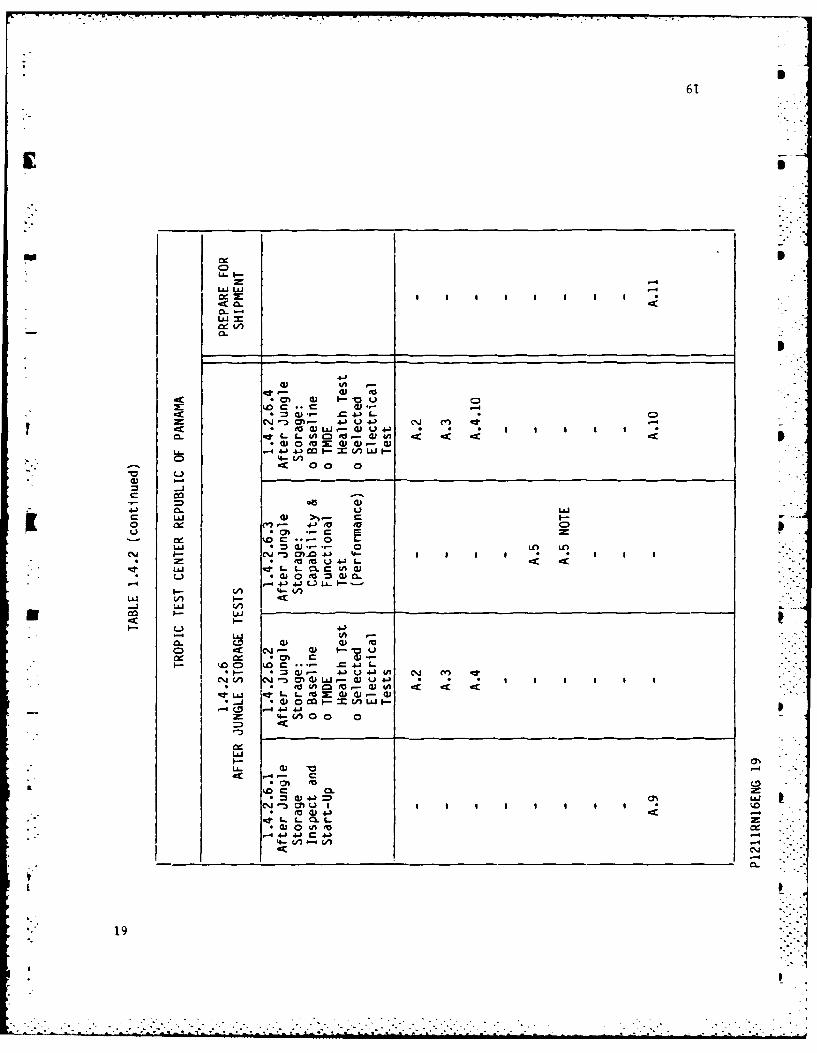
1.4.2 The conduct of the test is itemized in the subparagraphs below andconsists of contractor tests at San Jose, CA, prior to shipment toPanama plus the Operational and Diagnostic Tests both prior to andafter the storage periods. The intention is to have all of thetests consist of the same specific tests to allow comparison ofspecific results as the test progresses from start to finish.Specific tests are listed in appendix A and shown in table 1.4.2under each subparagraph of 1.4.2 in which they are to be performed.
o 300 miles of operationo Time-on-Target Baseline Testso Selected electrical and grounding circuit resistanceso Armament Firing (25mm, 7.62mm and TOW)o Fire Suppression System Validationo TMDE Validation Testso Validation of all vehicle subsystems
Details are included as Appendix A.
1.4.2.1 Contractor Baseline
In order to identify non-test related infant mortality failuresand to establish a traceable TMDE baseline, the contractor (FMC)will conduct a three-week baseline test at Camp Roberts andSan Jose, CA., prior to shipment. Reference FMC Test Pian 10186.
1.4.2.1.1 TMDE Baseline and Health Check
This test will be done in addition to the factory pre-deliveryTMDE check out. This will serve two purposes: 1) Establisha baseline with the same diagnostic equipment to be used at theTropic Test Center and 2) Serve as a training/demonstration forthe TTC personnel assigned to the Bradley program.
1.4.2.1.2 FMC 300 Mile Capability and Function Test
Ref: Table 1.4.2 for a list of each test and Appendix A fordetails of each test.
1.4.2.1.3 Post Contractor Capability Test: Baseline/TMDE Health Test, and
electe- Electrical tests
Ref: Table 1.4.2 and Appendix A.
1.4.2.2 TTC Pre Open Storage Testing
1.4.2.2.1 TTC - Receipt Inspection, Baseline TMDE Health Test and SelectedElectrical lests
Ref: Table 1.4.2 and Appendix A.
1.4.2.2.2 TTC - 300 Mile Capability and Functional Test
Ref: Table 1.4.2 and Appendix A.
1.4.2.2.3 Pre-Open Storage: Baseline TMDE Health Test and SelectedElectrical lests
Ref: Table 1.4.2 and Appendix A.
1.4.2.3 Open Storage
Ref: Table 1.4.2 and Appendix A.
P1211RN16ENG 10
0 -. -,-, . .
iS
1.4.2.4 Mid-Test
1.4.2.4.1 After Open Storage Inspection and Start-Up
Ref: Table 1.4.2 and Appendix A.1.4.2.4.2 After Open Storage Baseline, TMDE Health Test, and Selected
Electrical Tests.
Ref: Table 1.4.2 and Appendix A.
" 1.4.2.4.3 After Open Storage 300 Mile Capability and Functional Test
Ref: Table 1.4.2 and Appendix A.
1.4.2.4.4 Pre-Jungle Storage: Baseline, TMDE Health Tests, and SelectedElectrical Test.
Ref: Table 1.4.2 and Appendix A.
1.4.2.5 Jungle Storage
Ref: Table 1.4.2 and Appendix A.
i.4.2.6 After Jungle Storage Tests.
1.4.2.6.1 After Jungle Storage Inspection and Start-Up
Ref: Table 1.4.2 and Appendix A.
1.4.2.6.2 After Jungle Storage: Baseline, TMDE Health Test, and SelectedElectrical Tests.
Ref: Table 1.4.2 and Appendix A.
m 1.4.2.6.3 After Jungle Storage 300 Mile Capability and Functional Test.
Ref: Table 1.4.2 and Appendix A.
1.4.3 USATTC shall not be responsible to bring the vehicle to Class Bcondition prior to shipment.
1.4.4 RAM Evaluation is not a specific element of this test, however,EPRs will be written for all RAM related incidents and includedin the final report. EPRs will not be scored for RAM and anyRAM related evaluation will be of a qualitative nature only.
1.4.5 Safety evaluations are not specific elements of this test,however, EPRs will be written for all problems observed andincluded in the final report.
1.4.6 A Safety Assessment Report and a Safety Release required byAR385-16 will be provided by HQ, TECOM to USATTC. USATTC willnot begin testing until these documents are received.
1.4.7 The test officer and the USATTC Environmental QualityCoordinator will assess the environmental impact of this test.An environmental assessment/impact statement will be composed ifrequired. A record of environmental consideration will be madeand filed in the test officer's project file.
1.4.8 Coitractor personnel will supplement USATTC personnel asrequired. A trained military driver (TTC) with contractorgunner (FMC) will conduct the initial, mid and final 300 mileCapability Tests. A commander is TTC option. Basic contractorsupport consisting of one FMC Field Service Representative(FSR), one HAC technician/TSS-SE operator. Supplementalpersonnel for specific tests instrumentation work or problemswill be furnished as required.
1.4.9 Normal PMCS will be performed by the military supplied crew. -Equivalent organizational and direct support maintenance/repairwill be performed by contractor personnel with the support ofUSATTC personnel and equipment.
1.4.10 Security classification of the M3 and its armament systems willbe supplied to USATTC through HQ, TECOM.
1.4.11 Special Engineering tests may be conducted supplemental to theformal TTC test. Components may be installed in the vehicle by ;.the contractors. These will be not functional and will be -located so as to cause no interference to the formal test.These will be furnished and installed by the contractor andidentified as elements separate from the Maintenance Supportreturned unopened to the contractor. Purpose of this test is toenable a quantification of corrosion growth rates and to measure .- . -potential performance degradation.
1.4.12 Material, Personnel and Support requirements are summarized inAppendix D.
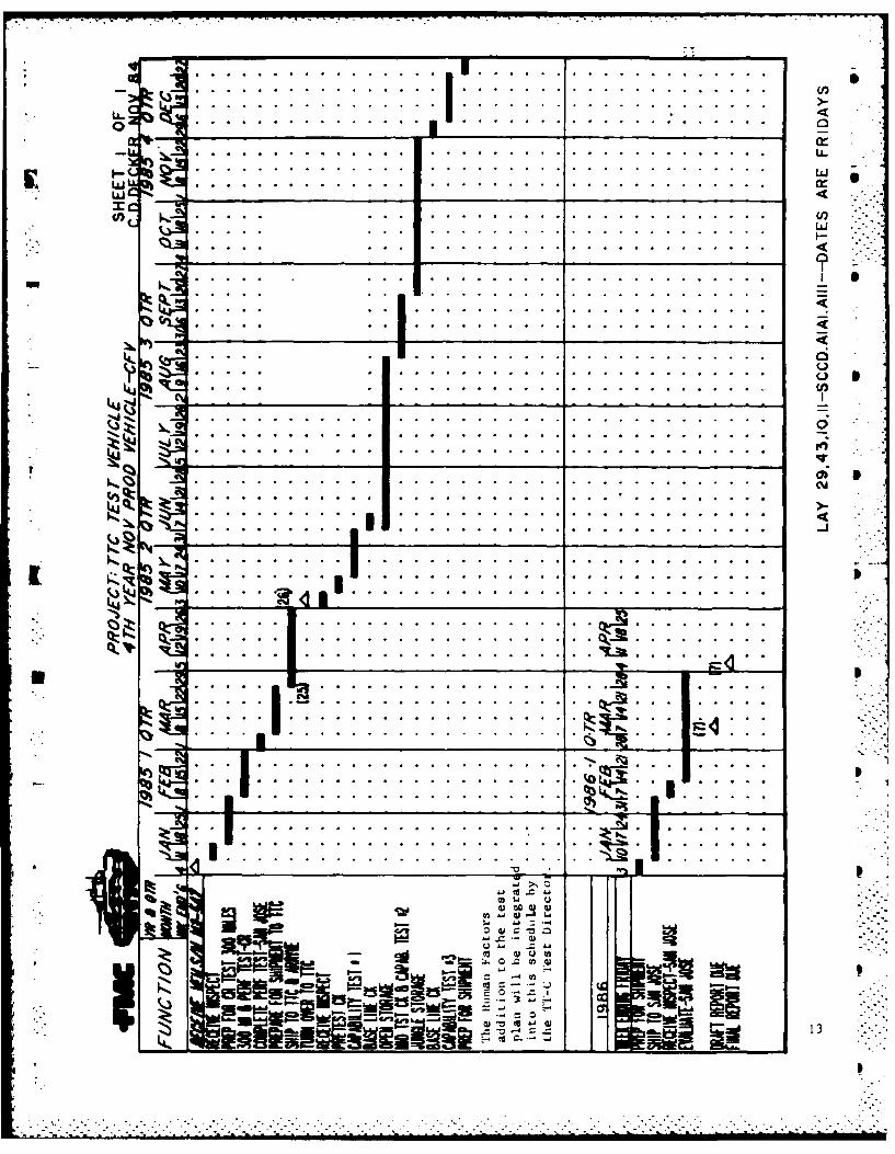
1.5 SCHEDULE
Schedule Milestones (See Schedule for Dates)
o Prepare for CR Test 300 Mileso Prepare for 300 Miles and Performance Test - Camp Roberts
(completed 8 Feb 85)o Complete Performance Test - San Joseo Prepare for Shipment to TTCo Ship to TTC and Arrival Dateo Complete Initial Baseline Checko Complete Open Storageo Complete Mid-Test Checko Complete Jungle Storageo Complete Testo Complete Shipment to San Joseo Complete Evaluation -San Joseo Draft Reporto Final Report
o Clean Vehicleo Repackage all BIIo Repackage FMC Designated Repairable Itemso Repackage unused Logistic Support Packageo Assure all ammo is removed from vehicleo Remove 25mm gun ass'y and stow within vehicle in original containero Return all contractor furnished equipment to on-site contractorso Prepare and ship TM 55-2350-252-14
2.1 LOGISTIC SUPPORT
o Initial Support Package
An Initial Support Package will be prepared by the contractor (FMC) andshipped with the vehicle. Because of the rapid response and capabilitiesof replenishment/replacement logistics, the Initial Supp9rt Package will beminimized to include only normal maintenance and known high demand items.
o Replenishment Support
Replenishment will be accomplished from the contractor (FMC) through GBL onthe Charleston, SC., to Howard AFB, Canal Zone military cargo flights.Emergency replenishment will be accomplished by commercial air carriers.
o Returning Failed Parts
Parts being returned for failure analysis will be sent by contractor (FMC)personnel to the appropriate subcontractor. Shipping from Panama will bevia GBL or commercial carrier if urgency dictates.
2.2 DATA/ANALYSIS REQUIREMENTS
The tropic test report will be an amalgamation of contractor-suppliedbaseline history data, contractor specific tests conducted and theiranalysis and USATTC test results. USATTC is responsible for final report.A status letter report will be supplied by USATTC to BFV PM no later than30 days following completion of both Mid-Test and Final Test CapabilityTests. -
Contractor Supplied Data
o Baseline STE-M1/FVS Results (FMC)- Pre-deli very- Pre-storage
S- Mid-test- Post-Storage Test
o Baseline TSS-TS Records (HAC)- Pre-delivery- Pre-storage- Mid-Test- Post-Storage -
*I o Time-on-Target Data (FMC Test Plan 10186)- Pre-delivery- Pre-Storage
o Electrical and Circuit Resistance Data (FMC)- Pre-delivery results- Instructions for Post-Test (See Appendix F)- Checks to be performed by USATTC (See Appendix F)
o Fire Suppression Check Out (FMC)- Pre-delivery records- Post-storage records
P1211RN16ENG 14
2.2 DATA/ANALYSIS REQUIREMENTS (continued)
Contractor Supplied Data (continued)
o TOW Flight Results (HAC)
o Post Test Electrical and Circuit Resistance Data
USATTC Supplied Data
o Receiving Inspection and Inventory Records
o EPRs for all incidents and maintenance actions
o All test records
o TOW Missile Firing Forms
o Human Factors and Safety Reports of all problems/hazards
0 o Meteorological data at site during storage phase:
- Total rainfall (nearest mm)- Ambient Air Temperatureo Maximumo Meano Minimum
-M3 Internal Air Temperatureo Maximumo Meano Minimum
- Total atmospheric salt fall (nearest 0.1 mg of C1/M2)
o Representative photographs and/or video recordings of all testing.
o Photographs documenting any observed material deterioration or damage.
o Narrative descriptions of unusual events or problems encountered.
o Water barrier fabric and seam deterioration test data. Test per.-. Appendix B.
- Pre-storage
- Mid-storage- Post-storage
P1211RN16ENG 15
2.2 DATA/ANALYSIS REQUIREMENTS (continued)
USATTC Supplied Data (continued)
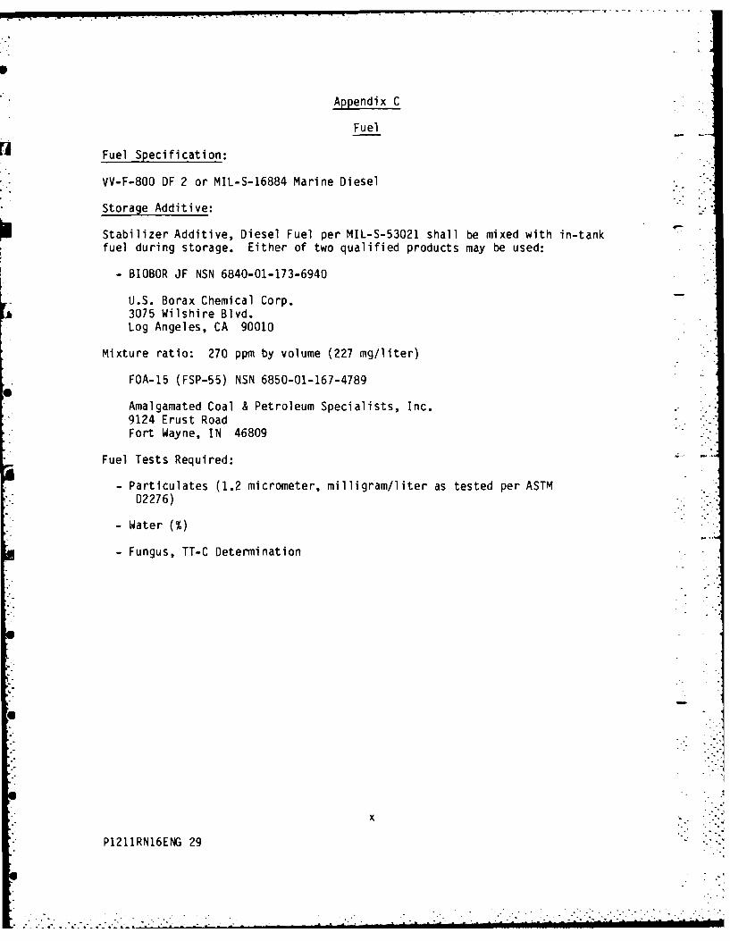
o Fuel sample analysis will be limited to measurement of water, fungusgrowth and sediment. Test per Appendix C. Samples will be analyzed:- Pre-storage- Mid-storage- Post-storage
o AOAP analysis of lube samples taken during normal PMCS as specified
in Lube Order.
o Vehicle Usage Log
o Gun Log Book
P1211RN16ENG 16
0 ' . , - . .
LI
(V Q r- col* 4~) WI.
(D* * CD ui
a - w- 'a .U- ~ ~ ~ 0 0.0 414. 10 U n
0. E M- - U4-
1U 0 0.mww .
* . - I(I,
0 CJO0l. Q;U.. I *I
C). 40jf0 3~0-n I. 0IVx 3a u +-
034-1 0 -C wCD 0M 00W 0
CD
I-4- 4J. 0~-MZ uj m w.I w V
C....) ~~4 *U*0J-0 LU
I- *0 *0. 0 .
- 4-.
itI IA -* 0. 0 03(D
00 a
03 I
CJ -0.341Ln - U) 0 03 .- O
L C~~~~0 0 1 1 1
I.C C.)
CdO ) ea3- = dia
*j 0.U0
Lii
+n -J4 C- CI-m.4
44 I- I. L.
0L .0 0 .. 0 0 ...- 4C 03LCL
17 .4141 A1- .i C% ' i
4-)lJ 00
C%.J (A 43.) I S1I* GJ D Qc
CMd - M 4) L
f- of= -
4-)
a) E
0.C *G ) tA) ~ .
LiS! CD mm m 4. 4-o~t U~C ) 4-04 L- J C ~ ~ '
*0 w L. 9- U=CL a 0
Ci I-- 0 0 to- = aC
4-- V).
CD
I-4 I-C.. 4.) UJ A j Y -r
C* =i "*D C 0) L.J- C ) -) t 0 I= to . IV 0
L4 C% OOZ- to- x cu I) I *(v * Cc I-- V.) L
I- 4- (,n00 0U~0).
I- 4
I Q CD cmu 1
4.1 %4)U
Lii '4 CAO 0a
*C- EUC 4-
0.NJ
18
61
C)
cc -4
uJ4J0~0
to~ a , CCU- i =
-4 41 4J 4 41J W ~
-cc0 00 0
4-' ULU
o..- 4- m U MC
* a*.*. 0 LOh fl).1.1~C- -,a CJ MO'0 -W 4d- 4 a I* S I
C% M M U 04J2
(U 0 =( a-
-i ui
-&) Q -)(AhC% ton 0 f W -0 -4
o~~ LM M~a a - W~ oua-* t X:o d).. C4)- 4
*i ( 0 ao (A.. UhI '. C)
cm *J 4 a
I-
#J = CA
-4 4J ,4 -W4
I4- con C/7C*%i
19
I
Appendix A
This Appendix list specific tests to be conducted as part of the BradleyTropic Test. SEE APPENDIX G FOR HUMAN FACTORS SUBTEST.
A.1 Receipt Inspection
A.1.1 An inventory of each container/crate shall be performed and shortageslisted as compared to the packing list. BII shall be inventoried andappropriate elements stowed on the vehicle.
A.1.2 All damages, whether physical damage or the result of water shall benoted. Photographic coverage shall be at the discretion of theProject Officer.
A.2 Baseline Checks
The tests/inspections are to insure that all systems are functioning/operational prior to proceeding with the Capability tests, failures/descrepancies will be noted and repaired prior to proceeding withtest. Before shipment the 13 LRU's will be run on FMC DSESTS set plusGFP DSESTS set destined for Panama. Printouts for record are requiredfrom both DSESTS tests run at FMC only. Retest following return toFMC at end of Panama test.
A.2.1 Boresight Retention
A.2.2 ISU Clarity and Night Sight Functionality (See Appendix E)
A.2.3 Back-up Sight vision clarity (See Appendix E)
A.2.4 Bilge pumps (4). (Back flushing is permissible--intent is to insureoperation prior to storage)
A.2.5 Proper ramp operation, use FRH fluid to refill
A.2.6 Driver's Instrument Panel Indicators
A.2.7 Weapon Control Panel
A.2.8 Intercom (all stations)
A.2.9 Deck clearance and interlock system (with and without override)
A.2.10 Interior Lights
A.2.11 Exterior lights including turn signals
A.2.12 Fire bottles at acceptable charge pressure (record)
A.2.18 A fuel sample shall be taken from the fuel filter after approximately 0one hour of operation. Test per Appendix C.
A.3 TMDE Health Tests and Selected Electrical Tests.
A.3.1 Turret Health Checko A health check of the turret, including TOW Subsystem shall be
conducted to assure readiness.
A.3.1.1 STE-M1/FVS: Conduct Test 2500 and 2501o These are "fast-run" tests intended for quick performance
validation rather than fault isolation. Procedures areattached. Ref. TM9-2350-252-20-1 pg 3-1339 thru 3-1342.LRU's failed should be run on DSESTS and failure I.D. codesrecorded for analysis.
A.3.1.2 TSS-TS:
o Hook-up Test Set: Ref. TM9-1425-474-34 pg 3-83o Run Self Test: Ref. TM9-1425-474-34 pg 3-105o Perform the following System Test Numbers:
1) Turret precondition2) PCU"3) CGE4) CGE LNCHR5) ISU/ISU TOW Visual Module (TVM) and Night Vision6) Basic Sight Assembly (BSA)7) ISU/Super Elevation Mirror Servo
A.3.2 Electrical and Grounding Circuit Resistance check will be performed toassess shipping degradation and to form baseline for test.Specific details of test are Appendix F of this test plan.
iiP2 I N.. .
P1211RN16ENG 21
S
Appendix A (continued)
A.3.3 Deleted.
A.3.4 The fire suppression system will be validated by FMC with check-outequipment obtained from SBRC and shipped with vehicle to Panama.
A.4 Preparation for Capability Tests.
A.4.1 Ballast shall not be installed, as it has insignificant effect on thepurpose of this test.
A.4.2 Radios and antennas shall be installed and internal/externalcommunication checked.
A.4.3 CVC helmet shall be issued to Driver, Gunner and Commander and
functionality checked.
A.4.4 The M242 cannon with its barrel shall be installed.
A.4.5 The M240C (MAG-58 7.62mm) machi.ne gun shall be installed.
A.4.6 A full complement of 25mm TPT ammo shall be loaded in each ready roundbox. Actual loading will be deferred to appropriate time of firingduring capability test.
A.4.7 A full complement of 7.62mm ammo shall be loaded in the ready roundbox. The weapon shall not be loaded. Actual loading will be deferredto appropriate time of firing during capability test.
A.4.8 Smoke grenades shall be loaded in the launchers. Rubber caps shall beinstalled. Actual loading will be deferred to appropriate time offiring during capability test.
A.4.9 The M240C, M242 and TOW shall be boresighted.
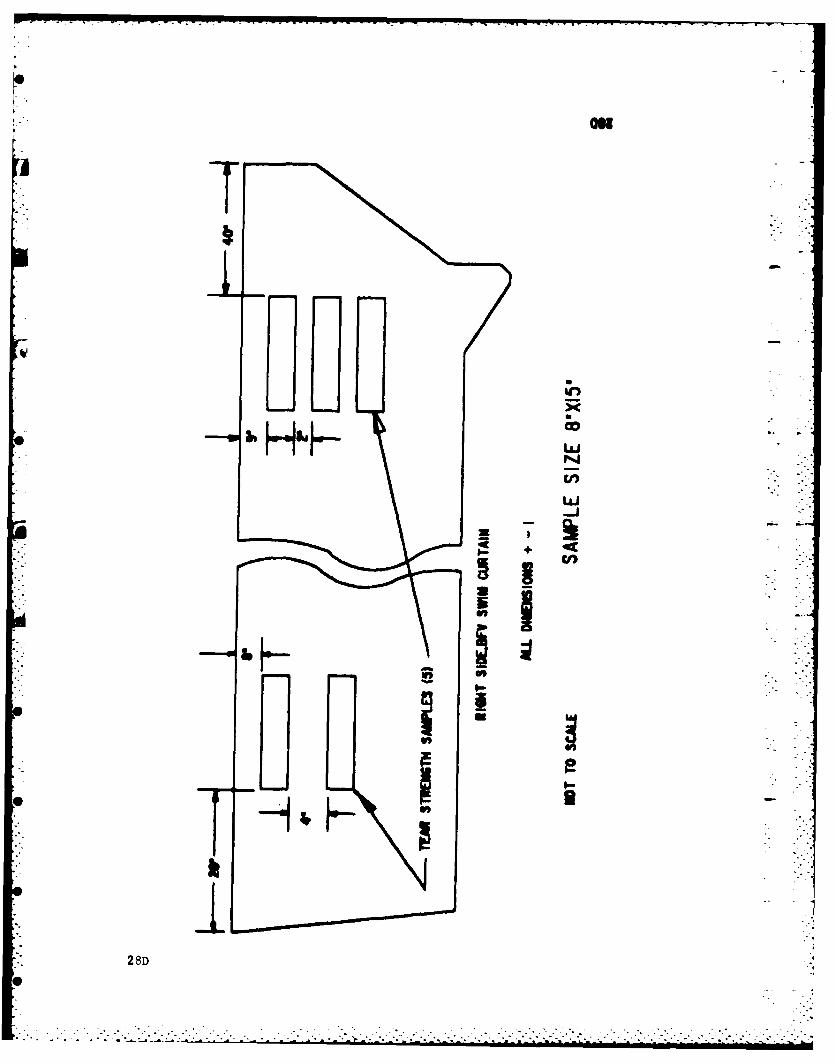
A.4.10 Cut the following samples from the water barrier.
1 - Warp & Fill Test Sample1 - Tear Strength Sample1 - Seam Sample
See Appendix B for details.
A.4.11 Two boxes of unopened 25mm ammo (1 ea of AP and HE) shall be placed inthe bilge' storage space. Location and lot shall be recorded.
Two additional boxes of 25mm ammo (1 ea of AP and HE) that have beenopened at both ends and re-closed shall be placed in the bilge storagespace. Location and lot shall be recorded.
iii
P1211RN16ENG 22
Appendix A (continued)
L A.4 Preparation for Capability Tests. (continued)
A.4.11 Note:
This to be performed as part of TTC preparation Para 1.4.2.2.1 only.The ammo is to remain stowed in the vehicle throughout the two 10 weekstorage periods then fired during the conduct of test Para 1.4.2.6.3.(Ammo and Links should be inspected per Par., A.9.3).
A.5 Capability Tests
A.5.1 300-Mile Operation
o A total of approximately 300 miles will be performed overestablished test course with the following.
Approximate Mix:
21% Paved45% Secondary Road34% Cross-Country
o Details and sequencing, shall be at the discretion of the testOfficer/Director/Engineer. Percentages of mileage may be revised toreflect less paved and more secondary road at the discretion of the" ". test officer. -
o Insure drain plugs are installed and tightened closed prior toa operation.
o Approximately 50% of all operation will be performed with the stab* system engaged and the ISU night sight ON.
A.5.2 25MM Gun System Firing
One ready box (300 rounds) 25mm TPT will be fired. The followingcapabilities shall be verified:
- Elevation from level to maximum allowable on range- All firing rates: Single shot, Lo rate, Hi rate
GHS (Gunners Hand Station)CHS (Commanders Hand Station)
Specific details of the preceeding are at Test Director discretion.An attempt shall be made to assess the cause of any stoppages beforeproceeding. Accuracy and dispersion is not part of Tropic Test andneed not be recorded. Of particular interest is any evidence ofdegradation of the ISU, Back-Up Sight, tracking and boresightretention.
NOTE: After jungle storage the four boxes of ammo (HE and AP) stowed in thebilge area shall be opened and inspected per A.9.3. Photographs to
* "show ammo condition should be made. Fire this ammo only followingboth open and jungle storage phases if ammo is determined to beservicable.
iv
P1211RN16ENG 23
. . . . . ..,
Appendix A 'continued
A.5 Capability Tests (continued)
A.5.3 7.62mm Gun System Firing
One ready box complement of 7.62 (800 rounds) will be fired.Elevation shall be from level to the maximum allowable on range. Anattempt shall be made to assess the cause of any stoppages beforeproceeding. Accuracy and dispersion is not part of Tropic Test andneed not be recorded.
A.5.4 TOW Missile Firing
Two TOW missiles will be fired, from the inboard tube. Minimumacceptable range is 1000 meters. Special instrumentation will be
installed and monitored by contractor (HAC) personnel in order toidentify any performance anomalies.
A.5.5 Smoke Grenade Firing
Eight smoke grenades will be fired to insure system functionality.
A.5.6 Time on Target
Time on Target capability of the system shall be tested throughvalidation of the control, sighting and servo drive systems. Thiswill be accomplished by measurement of the amount of time the gunneris able to maintain the gun on target (Time-on-Target) whiletraversing rough terrain. Measurement equipment, gunner and datareduction will be supplied by contractor (FMC). Data will be comparedthroughout the test to determine if degradation has occurred.
A.5.7 The engine exhaust smoke system shall be exercised to insure -
functionality.
A.5.8 Fire Suppression System
o Fire bottle pressure shall be verified and bottles replaced if belowacceptable limits. A pan fire shall be ignited in the crewcompartment. Automatic discharge of both crew compartment firebottles shall be verified. Actuation and extinguishing times havebeen prior validated, thus need not be measured for this test.
A.5.9 Normal PMCS (including guns) will be performed during this phase. -
(Mark lube order to use FRH in ramp hydraulic system)
A.5.10 TMDE will be available as required. Test sets will be stored in theequivalent of normal tropic area maintenance facilities. Location andtype of storage facility will be documented. All TMDE failure codesshould be recorded for analysis.
A.6.1 Fill fuel tank to top with VV-F-800 DF2 or MIL-S-16884 Marine Dieselmixed with Stablizer or additive per MIL-S-53021.
A.6.2 Operate engine at a fast idle for approximately 15 minutes to assurecomplete preservative/fuel mixture.
A.6.3 Operate smoke system for two minutes to insure preservative/fuel- mixture in system. S
A.6.4 Operate vehicle heater for 10 minutes to insure preservative/fuelmixture in system.
A.6.5 Insure batteries (vehicle and turret) are at 90 - 100% charge (S.G.reading). Replace if any cell is abnormally low.
A.6.6 A fuel sample will be taken from the fuel filter. Test perAppendix C.
A.6.7 The interior shall be washed of excessive mud accumulation. Hipressure hose washing of turret or electrical components is notpermitted. Low flow garden hose rinsing acceptable.
Normal PMCS (including guns) will be performed.
A.7 Configuration for Storage
A.7.1 Hatches, ramp, ISU sight cover closed and locked.
A.7.2 Water barrier stowed.
A.7.3 All external OVE not stowed - Stow inside of vehicle.
A.7.3.1 Engine stop control handle must be in full "OFF" position duringvehicle storage. (Malfunction can cause crankcase oil dilution)See page 28E.
A.7.4 Batteries disconnected - turn fire suppression switch OFF beforedisconnecting batteries.
A.7.5 Bilge plugs (4) open - (2 main large plugs and 2 final drive pipeplugs). Course mesh screens shall be installed to permit drainage.
A.7.6 TOW launcher canvas cover installed. S
A.7.7 M242 gun and Barrel installed.
A.7.8 M242 muzzle plug installed.
A.7.9 Gun chutes installed.
A.7.10 Gun bag closed.
*A.7.11 25mm Ready boxes loaded with full complement of 300 rounds of TPTammo, 230 rounds in the HE side and 70 rounds in the AP side.
vi
* P1211RN16ENG 25
. . .* . .".,
. . .* . *
. * .- , , ,
Appendix A (continued)
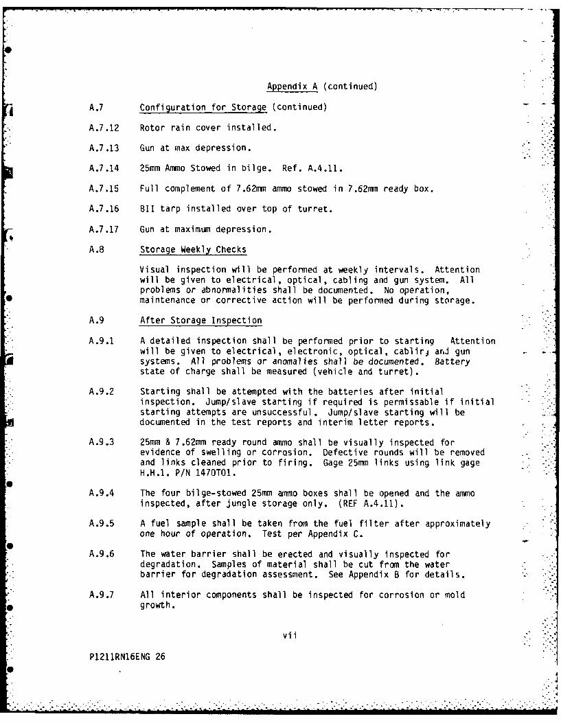
A.7 Configuration for Storage (continued)
A.7.12 Rotor rain cover installed.
A.7.13 Gun at max depression.
A.7.14 25mm Ammo Stowed in bilge. Ref. A.4.11.
A.7.15 Full complement of 7.62mm ammo stowed in 7.62m ready box.
A.7.16 BII tarp installed over top of turret.
A.7.17 Gun at maximum depression.
A.8 Storage Weekly Checks
Visual inspection will be performed at weekly intervals. Attentionwill be given to electrical, optical, cabling and gun system. Allproblems or abnormalities shall be documented. No operation,maintenance or corrective action will be performed during storage.
A.9 After Storage Inspection
A.9.1 A detailed inspection shall be performed prior to starting Attentionwill be given to electrical, electronic, optical, cablirj arJ gunsystems. All problems or anomalies shall be documented. Batterystate of charge shall be measured (vehicle and turret).
A.9.2 Starting shall be attempted with the batteries after initialinspection. Jump/slave starting if required is permissable if initialstarting attempts are unsuccessful. Jump/slave starting will bedocumented in the test reports and interim letter reports.
A.9.3 25mm & 7.62mm ready round ammo shall be visually inspected forevidence of swelling or corrosion. Defective rounds will be removedand links cleaned prior to firing. Gage 25mm links using link gageH.H.1. P/N 1470T01.
A.9.4 The four bilge-stowed 25mm ammo boxes shall be opened and the ammoinspected, after jungle storage only. (REF A.4.11).
A.9.5 A fuel sample shall be taken from the fuel filter after approximatelyone hour of operation. Test per Appendix C.
A.9.6 The water barrier shall be erected and visually inspected fordegradation. Samples of material shall be cut from the waterbarrier for degradation assessment. See Appendix B for details.
A.9.7 All interior components shall be inspected for corrosion or moldgrowth.
P1211RN16ENG 26
-- -"""0 . i~ j i " -"' "''"""" "
. ... . . . . . . .. . . . . _ .... Ill. I p* it 111.II...
S
Appendix A (continued)
I) A.9 After Storage Inspection (continued)
A.9.8 Special attention shall be given to the gun/gun mounting system forrust and corrosion.
A.10 Final Inspection prior to shipping
A final inspection shall be performed at completion of contractor andTTC tests. Particular attention should be addressed to possiblelossening fasteners and sticking/binding mechanisms.
A.11 Shipping
Vehicle shipping configuration shall be as follows:
o Fuel tanks drained to no more than 1/4 tank.o All external components shall be stored within vehicle.o All BI1 shall be stored within vehicle.o The M242 gun shall be stored within the vehicle in its (3) shipping
containers.o Chutes shall be removed from the ammo cans, 25mm and 7.62mm and
packed to prevent shipping damage.o Shipping guidance is provided per TM 55-2350-252-14.
The Logistics Support Package shall be shipped with the vehicle.
de P
4.o
i vi ii"
; P121IRN16ENG 27
Appendix Bwater b~arrier
Speci fi cati on:
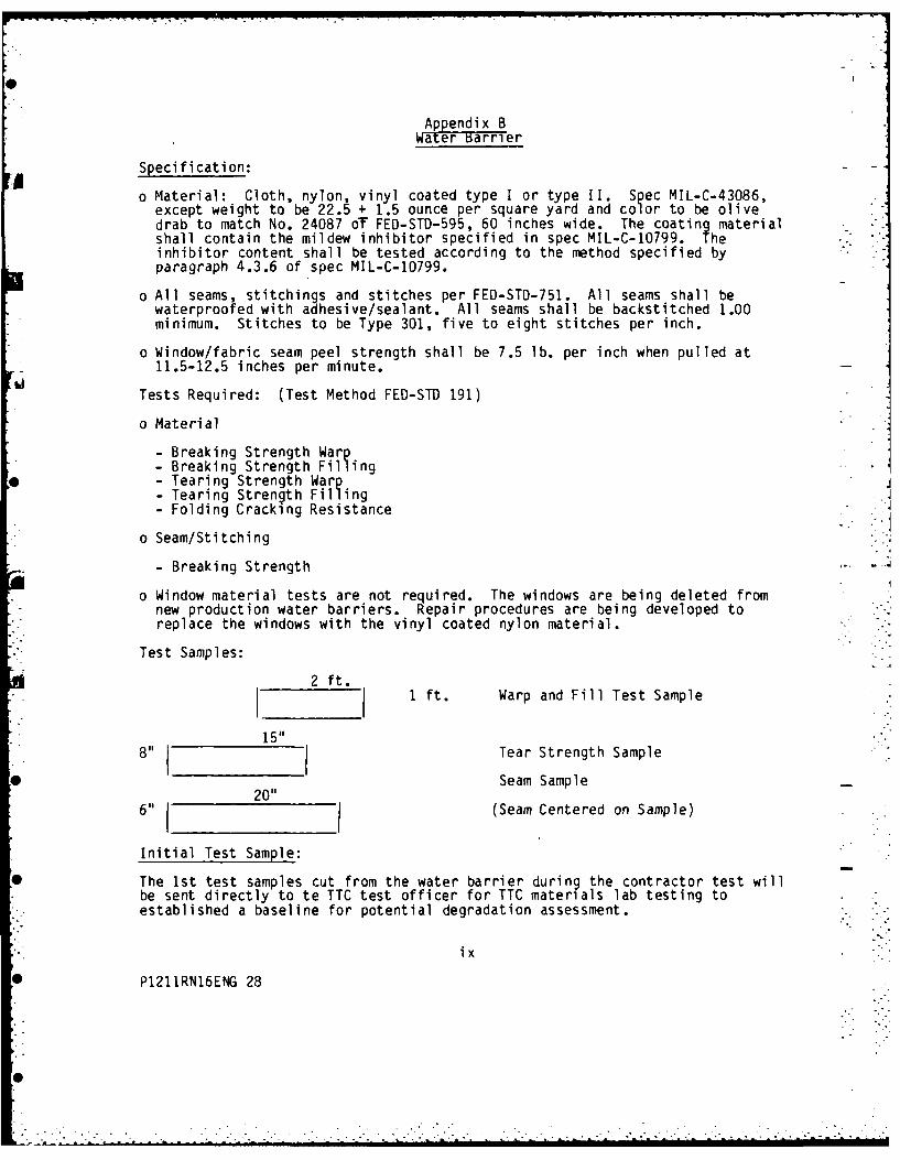
o Material: Cloth, nylon, vinyl coated type I or type I. Spec MIL-C-43086,except weight to be 22.5 + 1.5 ounce per square yard and color to be olivedrab to match No. 24087 oT FED-STD-595, 60 inches wide. The coating materialshall contain the mildew inhibitor specified in spec MIL-C-10799. Theinhibitor content shall be tested according to the method specified byparagraph 4.3.6 of spec MIL-C-10799.
o All seams, stitchings and stitches per FED-STD-751. All seams shall bewaterproofed with adhesive/sealant. All seams shall be backstitched 1.00minimum. Stitches to be Type 301, five to eight stitches per inch.
o Window/fabric seam peel strength shall be 7.5 lb. per inch when pulled at
o Window material tests are not required. The windows are being deleted fromnew production water barriers. Repair procedures are being developed toreplace the windows with the vinyl coated nylon material.
Test Samples:
2 ft. 2 1 ft. Warp and Fill Test Sample
15"
8" Tear Strength SampleSeam Sample
20"6" (Seam Centered on Sample)
Initial Test Sample:
The 1st test samples cut from the water barrier during the contractor test willbe sent directly to te TTC test officer for TTC materials lab testing toestablished a baseline for potential degradation assessment.
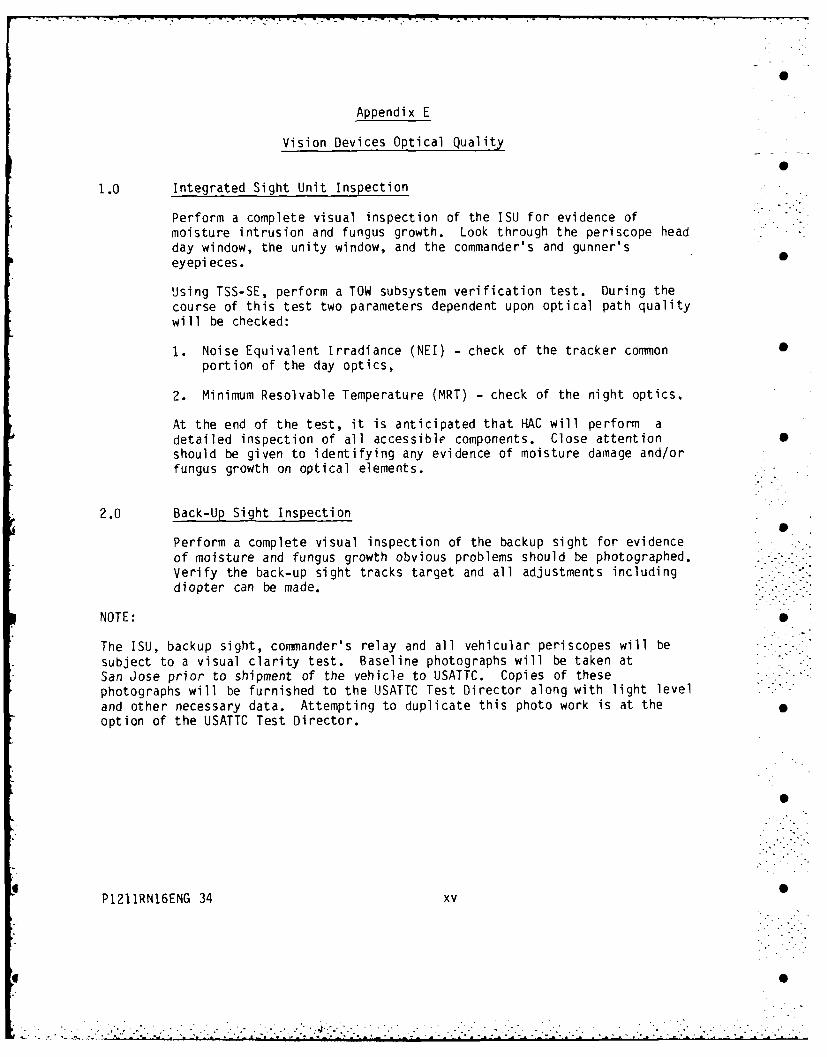
Perform a complete visual inspection of the ISU for evidence ofmoisture intrusion and fungus growth. Look through the periscope headday window, the unity window, and the commander's and gunner'seyepi eces.
Using TSS-SE, perform a TOW subsystem verification test. During thecourse of this test two parameters dependent upon optical path qualitywill be checked:
1. Noise Equivalent Irradiance (NEI) - check of the tracker common 0portion of the day optics,
2. Minimum Resolvable Temperature (MRT) - check of the night optics.
At the end of the test, it is anticipated that HAC will perform adetailed inspection of all accessible components. Close attention 0should be given to identifying any evidence of moisture damage and/orfungus growth on optical elements.
2.0 Back-Up Sight Inspection
Perform a complete visual inspection of the backup sight for evidenceof moisture and fungus growth obvious problems should be photographed. . -
Verify the back-up sight tracks target and all adjustments includingdiopter can be made.
NOTE:
The ISU, backup sight, commander's relay and all vehicular periscopes will be -
subject to a visual clarity test. Baseline photographs will be taken atSan Jose prior to shipment of the vehicle to USATTC. Copies of thesephotographs will be furnished to the USATTC Test Director along with light leveland other necessary data. Attempting to duplicate this photo work is at theoption of the USATTC Test Director.
P1211RN16ENG 34 xv
• * ,0 o
Date
Test Sequence
Appendix F
Ground Circuit Resistance Testing
Objective: Determine the degradation of electrical/electronic systems withexposure to tropic environment.
This document establishes test procedures to accomplish the stated ohjective andspecifically fulfill 1.4.2, bullet 3 of the basic test plan.
Equipment
Milliohmeter, Hewlett-Packard Model #4328AProbe cable, Hewlett-Packard #16143ATest Lead adapter, Hewlett-Packard #16007A/B (Modified)2 Ea. Test Leads, 5 Foot long with large clamps.I gun connector adaptor.
Vehicle Preparation
Prior to any measurements on the vehicle, place the Fire Suppression Switch inthe manual position. Clean dirt accumulated and/or paint from the three groundreferences (see 1.1.0, 1.2.0, 2.0).
Equipment checkoutLero the test meter before making any measurements. Do not allow loops to formin the test leads at any time during the test as it can influence the test meterreading. Measure resistance of the red and black leads clamped together andrecord the reading.
Note; The test vehicle was baselined at FMC/San Jose using the above specified
Model Milliohmeter S/N 1828J06830.
1.1.0 Procedure:
For the following tests, connect one test lead to the right rear bilgepump electrical ground stud on the hull. Connect the other test lead tothe shell of the electrical connector (unless otherwise indicated) of theitem being tested.
1.1.1 Right Rear Bilge Pump
6 I
1.1.2 Left Rear Dome Light - hull mounting screw nearest the on/off switch
1.1.6 Fire Sensor Blocks The crew compartment contains three fire sensor Sblocks. One is located at the right rear near the ramp and two othersare located on the ceiling behind the driver.
1rear [ R.. -:
1.2.0 For the following tests, connect one test lead to the battery electricalground stud for the vehicle batteries. This stud is located on thesponson near the drivers station. Connect the other test lead to theshell of the electrical connector (unless otherwise indicated) of theitem being tested.
1.2.1 Fire Suppression Amplifier (Located on drivers forward bulkhead)
1.2.4 Drivers Instrument Panel - clamp to the panel between turn indicatorand light switches
1.2.5 Drivers Dome Light - hull mounting screw nearest the on/off switch
1.2.6 Vehicle Battery - left rear battery negative terminal
1.2.7 Rear hull ground reference stud (ground stud for right rear bilge pump).
2.0 For the following tests, connect one test lead to the turret basketcenter ground stud located under the stepwell floorplate. Connect theother test lead to the shell of the electrical connector (unlessotherwise indicated) of the item being tested.
2.1 Rear hull ground reference stud (ground stud for right rear bilge pump)
2.2 Encoder
2.3 Turret Battery - right side battery negative terminal
2.13 Azimuth Drive - ground strap bolt on the drive
2.14 Commanders Dome Light - hull mounting screw nearest the on/off switch
2.15 Gunners Dome Light - hull mounting screw nearest the on/off switch
2.16 TOW Control Box/ Annunciator - left mounting screw holding the twounits together
2.17 Integrated Sight Unit-(4 connectors)
Front Mid Back Test
I __.2.18 Electronic Control Assembly - measure from connector shells J1 through
J9 plus from the ground strap bolt on the ECA
LI I I+ I2.19 Gun Elevation Drive - ground strap bolt on the drive
2.20 For the following test, disconnect the meter test lead from the groundreference stud
2W10 Gun Connector (25mm Gun) Measure between pin A and pin J usingadaptor connector. Push in on connector pins A and J of adaptorconnector to insure good contact when mated
The test is now complete. Be certain all measurements have beenrecorded.
P1211RN16ENG 39 xx
.- - - - - - - - - - - - - - - - - - - - - -
. . .. . . . . . . . . . .
Appendix G
HUMAN FACTORS SUBTEST PLAN
1. Purpose
The purpose of this test is to measure and document specific HFE time and error
data of each functional exercise specified in Reference 14a of this plan. This
test is not intended to impact Appendix A, preparation for capability test or
preparation for storage test or stowage configuration. Human Factors aspects of
firing, turret and vehicle operation shall be collected from the TTC Driver/Gun-
ner by the TTC test director.
2. Scope
The time required to load the M3 Bradley (CFV) weapon systems with ammunition in
a tropic environment will be determined. Individual time will be recorded for
loading the HE and AP sides of the 25mm Gun System, loading of the 7.62mm
coaxial machine gun and the TOW Missile Launcher (TML).
This loading exercise should be accomplished one time during the Phase 1 and
one time during the Phase 3 portion of the tropic test. Video documentation of
entire loading exercise is requested.
3. Personnel
The ability of vehicle crewmen to perform critical weapon loading tasks while
dressed in standard fatigues will be determined.
P
Pl211RN16ENG 40 -"
...........................................
Appendix G (continued)
Human Factors Subtest (continued) "
The commander, gunner, and driver will wear the DH-132 CVC helmet and the squad
members will wear the protective-armor system for ground troops (PASGT) (helmet
and vest) with load-bearing equipment (LBE).
MOS-qualified military personnel, trained and experienced in the operation ofthe vehicle and its associated weapons, will perform the following exercises in
a partially stowed vehicle. These personnel will be furnished by TECOM/APG.
4. Test Procedure
4.1 Ammunition Stowage
The 25mm ammunition shall be placed in the vehicle squad compartment, the 7.62mm
ammunition shall be stowed in the Vehicle Left Side Interior, the weighted TOW -*
missile cannisters shall be stowed in the vehicle. All of the above stowage
Locations are illustrated in appendix E of operations manual TM 9-2350-252-10-1.
4.2 Criteria
The loading of the 25mm AP and HE ammunition READY boxes plus the 7.62mm coaxial
machine gun shall be accomplished concurrently to the greatest extent feasible.
Ammunition handling/loading will be conducted during daylight. The M3 crew- and
squad-seating arrangement during these exercises is shown in figure -1 (page
41A)
4.3 The 7.62-mm Coaxial Machinegun Loading
Turret/weapon systems will be positioned at 00 in azimuth and elevation. Timing
0 will begin when the commaader and squad member No. 4, seated in their respective
stations, are cued to commence 7.62-mm machinegun loading. Squad member No. 4
will then remove 7.62-mm ammunition from stowage, check alinement, and hand
ammunition through the turret opening to the commander. Time is stopped when a
full compliment of 800 rounds has been loaded into the 7.62-mm ready-ammunition
container and the lead rounds have been forwarded up to the weapon.
P1211RN16ENG 41
RES 5-21-85
FIGURES
0RWADSUDSAIN OIIN CVPAGE41AAPPEDIXG TRPICTESTPLA
Im
Appendix G (continued)
Human Factors Subtest (continued)
4.4 TOW Missile Loading
Turret will be rotated, and TOW launchers elevated to their designated positions
for TOW loading prior to conduct of the timed run. Timing will begin when squad
members No. 4 and No. 5 are cued to commence TOW loading. Squad member No. 4
will then open and secure the cargo hatch in the TOW-loading position and beginb to remove and discard empty canisters from TOW launcher (assuming previous TOW
fire). At the same time, squad member No. 5 removes the first missile from its
stowed position and hands it to No. 4 who raises and loads the missile into the
launcher. Procedure is repeated for the second missile. Time stops when cargo
hatch is closed and latched.
4.5 The 25-mm Automatic Cannon Loading
Turret will be rotated to the right or left for positioning to upload/download
HE or AP ammunition, respectively, prior to commencement of the timed run.
4.5.1 Uploading
Timing will begin upon cue to load 25-mm HE or AP ready-ammunition containers,
at which point squad member No. 5 unstows 25-mm ammunition, links, and checks
alinement. Squad member No. 4, having removed the container door, loads the
ammunition that is handed to him by No. 5, counting rounds to obtain the
required number within each vertically hung row. Squad member No. 5 continues
to link and check alinement of ammunition. Time is stopped when a full
compliment of HE (230) or AP (70) rounds have been loaded into the respective
ready-ammunition containers, and squad member No..4 has replaced and latched the
container door.
P1211RN16ENG 42
Appendix G (continued)
Human Factors Subtest (continued)
4.5.2 Downloading
HE or AP ammunition has been forwarded up through the respective chutes;
and no rounds are present in the feeder.
Timing will begin upon cue to download. The gunner will then begin to ratchet
the rounds down through the feed chutes. Squad member No. 4, having removed the
ammunition container door, pulls the rounds from the railings. Squad member
No. 5 assists from behind. Timing is stopped when all rounds have been removed
from the feed chutes and the ready ammunition container, and the container door
is replaced and latched.
5. Safety Requirements
All of the safety requirements in the M2 and M3 Safety Statement, operators .
manual TM 9-2350-252-10-1 and TM 9-2350-252-10-2 shall be the topic of a safety
meeting. This meeting, conducted by the tropic test center Bradley vehicle test
director shall be conducted for the personnel used as the weapon systems loading
crew. In addition to the TM safety requirements, the weapon system loading crew
should be advised of the peculiarities of working in the TTC environment. .
5.1 Reliability and Maintainability (RAM)
RAM is not a specific element of this HFE portion of the overall TTC test 5
however EPRs should document all RAM related incidents and be included in the
final report.
Any incident or condition that would invalidate the results of this HFE test S
should be recorded along with the time delay incurred.
P1211RN16ENG 43 0
. . .
Appendix G (continued)
Human Factors Subtest (continued)
6. Changes in Schedule and Scope
The HF Test Director may change the scope of work by making additions or
deletions, revise the schedule or order of exercises or make other appropiate
changes with concurrence of the Bradley PM Office. Such changes can be made as
required to accomplish the HF test goals as may be inpacted by availability of
test parts or severe environmental conditions.
7. Documentation
A. Recording of weapon system loading exercise times should be documented on
appropriate forms and included in the final Tropic test report for the
Bradley vehicle. Time and error data shall be recorded. -.
B. Completed interview guides from each crew member for each exercise.
STEAP-MT Form 402 Questionaire as applicable or other documentation
designated by the HF Test Director.
C. These data from the various HFE tests will be used to evaluate the test
criteria.
C.1 The subjective data from the questionnaires, check lists, and user comments
will be used to supplement the objective data.
P1211RN16ENG 44
. -°'
Appendix G (continued)
Human Factors Subtest (continued)
7.1 Subjective Evaluation.
Questionnaires. Human factors questionnaires will be administered to all crew
and squad personnel assigned to operate the vehicle. Questionnaires will be
administered near the end of the test cycle so that all personnel will be
thoroughly experienced with vehicle operations.
Questionnaires will pertain to the operation of the driver, gunner, commander,
and squad stations.
Comments and informal interviews, in addition to HFE observations, will be
documented throughout HFE testing to gain additional subjective input to the HFE
assessment of the vehicle. These interviews, comments, and observations may be .
used to augment the data from other HFE subtests and will be integrated into the