25
Adafruit GFX Graphics Library Created by Phillip Burgess Last updated on 2020-11-19 04:53:27 PM EST
Adafruit GFX Graphics LibraryCreated by Phillip Burgess
Last updated on 2020-11-19 04:53:27 PM EST

Overview
The Adafruit_GFX library for Arduino provides a common syntax and set of graphics functions for all of our
LCD and OLED displays. This allows Arduino sketches to easily be adapted between display types with
minimal fuss…and any new features, performance improvements and bug fixes will immediately apply
across our complete offering of color displays.
The Adafruit_GFX library can be installed using the Arduino Library Manager…this is the preferred and
modern way. From the Arduino “Sketch” menu, select “Include Library” then “Manage Libraries…”
Type “gfx” in the search field to find it quickly:
While you’re there, also look for and install the Adafruit_BusIO library (or…newer Arduino IDE versions
© Adafruit Industries https://learn.adafruit.com/adafruit-gfx-graphics-library Page 3 of 26

install this dependency automatically).
The Adafruit_GFX library always works together with an additional library unique to each specific display
type — for example, the ST7735 1.8" color LCD requires installing Adafruit_GFX, Adafruit_BusIO and the
Adafruit_ST7735 library. The following libraries now operate in this manner:
RGBmatrixPanel (https://adafru.it/aHj), for our 16x32 (http://adafru.it/420) and
32x32 (http://adafru.it/607) RGB LED matrix panels.
Adafruit_TFTLCD (https://adafru.it/aHk), for our 2.8" TFT LCD touchscreen
breakout (http://adafru.it/335) and TFT Touch Shield for Arduino (http://adafru.it/376).
Adafruit_HX8340B (https://adafru.it/aHl), for our 2.2" TFT Display with microSD (http://adafru.it/797).
Adafruit_ST7735 (https://adafru.it/aHm), for our 1.8" TFT Display with microSD (http://adafru.it/358).
Adafruit_PCD8544 (https://adafru.it/aHn), for the Nokia 5110/3310 monochrome
LCD (http://adafru.it/338).
Adafruit-Graphic-VFD-Display-Library (https://adafru.it/aHo), for our 128x64 Graphic
VFD (http://adafru.it/773).
Adafruit-SSD1331-OLED-Driver-Library-for-Arduino (https://adafru.it/aHp) for the 0.96" 16-bit Color
OLED w/microSD Holder (http://adafru.it/684).
Adafruit_SSD1306 (https://adafru.it/aHq) for the Monochrome 128x64 (http://adafru.it/326) and
128x32 (http://adafru.it/661) OLEDs.
and many many others!
The libraries are written in C++ for Arduino but could easily be ported to any microcontroller by rewriting
the low-level pin access functions.
The Old WayOlder versions of the Arduino IDE software require installing libraries manually; the Arduino Library
Manager did not yet exist. If using an early version of the Arduino software, this might be a good time to
upgrade. Otherwise, this tutorial explains how to install and use Arduino libraries (https://adafru.it/aYG).
Here are links to download the GFX and BusIO libraries directly (use the links above to get the
corresponding display-specific libraries):
https://adafru.it/cBB
https://adafru.it/Ldl
https://adafru.it/cBB
https://adafru.it/Ldl
© Adafruit Industries https://learn.adafruit.com/adafruit-gfx-graphics-library Page 4 of 26

Coordinate System and UnitsPixels — picture elements, the blocks comprising a digital image — are addressed by their horizontal (X)
and vertical (Y) coordinates. The coordinate system places the origin (0,0) at the top left corner, with
positive X increasing to the right and positive Y increasing downward. This is upside-down relative to the
standard Cartesian coordinate system of mathematics, but is established practice in many computer
graphics systems (a throwback to the days of raster-scan CRT graphics, which worked top-to-bottom). To
use a tall “portrait” layout rather than wide “landscape” format, or if physical constraints dictate the
orientation of a display in an enclosure, one of four rotation settings can also be applied, indicating which
corner of the display represents the top left.
Also unlike the mathematical Cartesian coordinate system, points here have dimension — they are always
one full integer pixel wide and tall.
Coordinates are always expressed in pixel units; there is no implicit scale to a real-world measure like
millimeters or inches, and the size of a displayed graphic will be a function of that specific display’s dotpitch or pixel density. If you’re aiming for a real-world dimension, you’ll need to scale your coordinates to
suit. Dot pitch can often be found in the device datasheet, or by measuring the screen width and dividing
the number of pixels across by this measurement.
For color-capable displays, colors are represented as unsigned 16-bit values. Some displays may
physically be capable of more or fewer bits than this, but the library operates with 16-bit values…these are
easy for the Arduino to work with while also providing a consistent data type across all the different
displays. The primary color components — red, green and blue — are all “packed” into a single 16-bit
variable, with the most significant 5 bits conveying red, middle 6 bits conveying green, and least
significant 5 bits conveying blue. That extra bit is assigned to green because our eyes are most sensitive
to green light. Science!
For the most common primary and secondary colors, we have this handy cheat-sheet that you can include
© Adafruit Industries https://learn.adafruit.com/adafruit-gfx-graphics-library Page 5 of 26

in your own code. Of course, you can pick any of 65,536 different colors, but this basic list may be easiest
when starting out:
// Color definitions#define BLACK 0x0000#define BLUE 0x001F#define RED 0xF800#define GREEN 0x07E0#define CYAN 0x07FF#define MAGENTA 0xF81F#define YELLOW 0xFFE0 #define WHITE 0xFFFF
For monochrome (single-color) displays, colors are always specified as simply 1 (set) or 0 (clear). The
semantics of set/clear are specific to the type of display: with something like a luminous OLED display, a
“set” pixel is lighted, whereas with a reflective LCD display, a “set” pixel is typically dark. There may be
exceptions, but generally you can count on 0 (clear) representing the default background state for a
freshly-initialized display, whatever that works out to be.
© Adafruit Industries https://learn.adafruit.com/adafruit-gfx-graphics-library Page 6 of 26

Graphics PrimitivesEach device-specific display library will have its own constructors and initialization functions. These are
documented in the individual tutorials for each display type, or oftentimes are evident in the specific
library header file. The remainder of this tutorial covers the common graphics functions that work the
same regardless of the display type.
The function descriptions below are merely prototypes — there’s an assumption that a display object is
declared and initialized as needed by the device-specific library. Look at the example code with each
library to see it in actual use. For example, where we show print(1234.56), your actual code would place
the object name before this, e.g. it might read screen.print(1234.56) (if you have declared your display
object with the name screen).
Drawing pixels (points)First up is the most basic pixel pusher. You can call this with X, Y coordinates and a color and it will make
a single dot:
void drawPixel(uint16_t x, uint16_t y, uint16_t color);
Drawing linesYou can also draw lines, with a starting and end point and color:
void drawLine(uint16_t x0, uint16_t y0, uint16_t x1, uint16_t y1, uint16_t color);
© Adafruit Industries https://learn.adafruit.com/adafruit-gfx-graphics-library Page 7 of 26

For horizontal or vertical lines, there are optimized line-drawing functions that avoid the angular
calculations:
void drawFastVLine(uint16_t x0, uint16_t y0, uint16_t length, uint16_t color);void drawFastHLine(uint8_t x0, uint8_t y0, uint8_t length, uint16_t color);
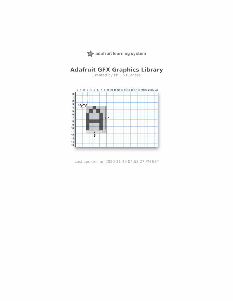
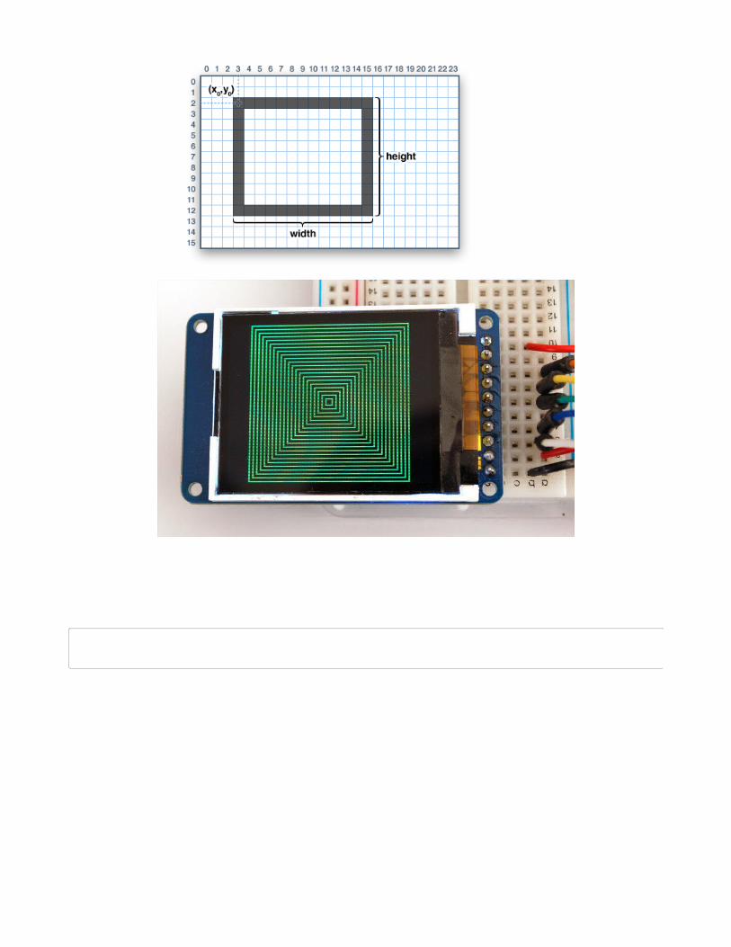
RectanglesNext up, rectangles and squares can be drawn and filled using the following procedures. Each accepts an
X, Y pair for the top-left corner of the rectangle, a width and height (in pixels), and a
color. drawRect() renders just the frame (outline) of the rectangle — the interior is unaffected —
while fillRect() fills the entire area with a given color:
void drawRect(uint16_t x0, uint16_t y0, uint16_t w, uint16_t h, uint16_t color);void fillRect(uint16_t x0, uint16_t y0, uint16_t w, uint16_t h, uint16_t color);
© Adafruit Industries https://learn.adafruit.com/adafruit-gfx-graphics-library Page 8 of 26
To create a solid rectangle with a contrasting outline, use fillRect() first, then drawRect() over it.
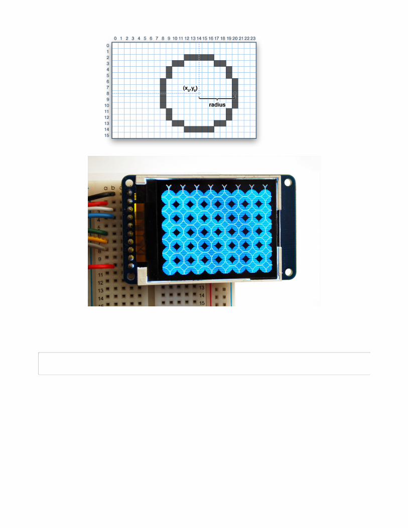
CirclesLikewise, for circles, you can draw and fill. Each function accepts an X, Y pair for the center point, a radius
in pixels, and a color:
void drawCircle(uint16_t x0, uint16_t y0, uint16_t r, uint16_t color);void fillCircle(uint16_t x0, uint16_t y0, uint16_t r, uint16_t color);
© Adafruit Industries https://learn.adafruit.com/adafruit-gfx-graphics-library Page 9 of 26
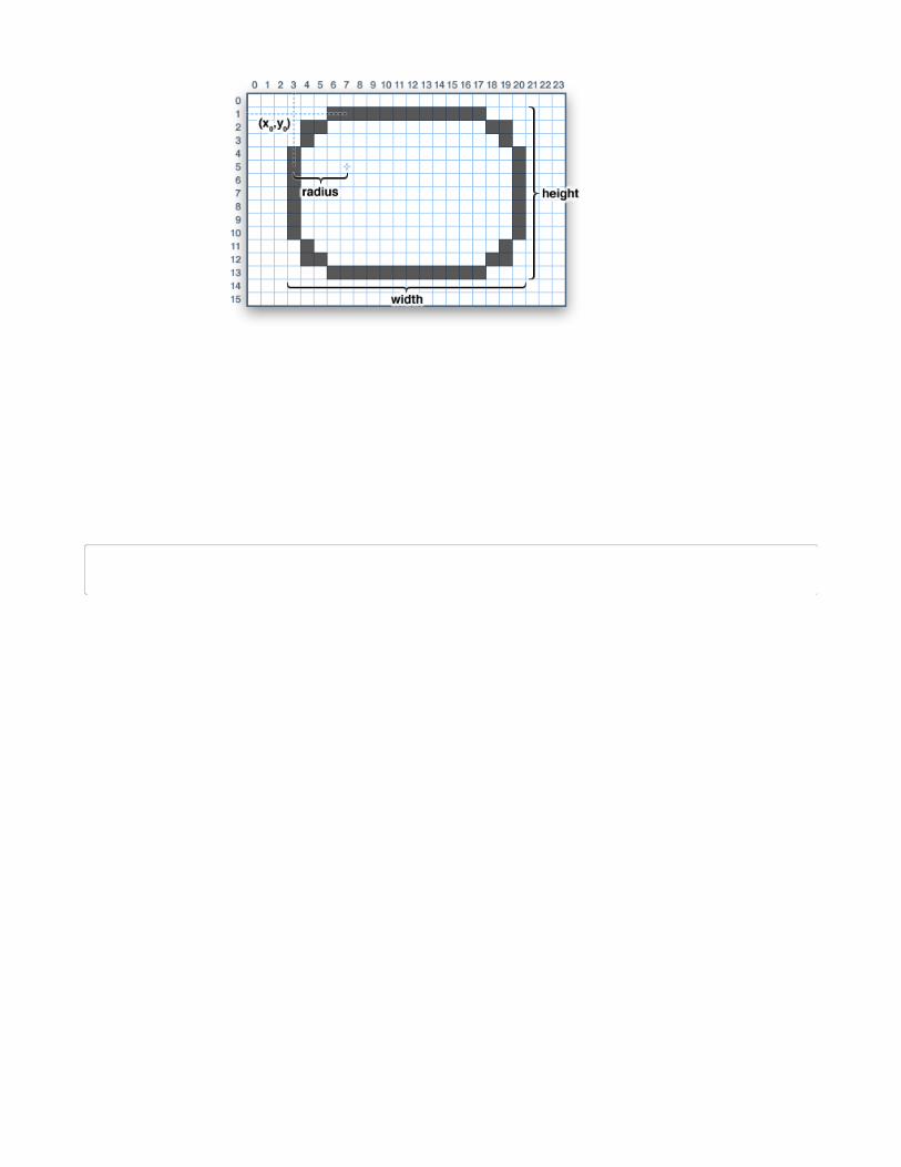
Rounded rectanglesFor rectangles with rounded corners, both draw and fill functions are again available. Each begins with an
X, Y, width and height (just like normal rectangles), then there’s a corner radius (in pixels) and finally the
color value:
void drawRoundRect(uint16_t x0, uint16_t y0, uint16_t w, uint16_t h, uint16_t radius, uint16_t color);void fillRoundRect(uint16_t x0, uint16_t y0, uint16_t w, uint16_t h, uint16_t radius, uint16_t color);
© Adafruit Industries https://learn.adafruit.com/adafruit-gfx-graphics-library Page 10 of 26
Here’s an added bonus trick: because the circle functions are always drawn relative to a center pixel, the
resulting circle diameter will always be an odd number of pixels. If an even-sized circle is required (which
would place the center point between pixels), this can be achieved using one of the rounded rectangle
functions: pass an identical width and height that are even values, and a corner radius that’s exactly half
this value.
TrianglesWith triangles, once again there are the draw and fill functions. Each requires a full seven parameters: the
X, Y coordinates for three corner points defining the triangle, followed by a color:
void drawTriangle(uint16_t x0, uint16_t y0, uint16_t x1, uint16_t y1, uint16_t x2, uint16_t y2, uint16_t color);void fillTriangle(uint16_t x0, uint16_t y0, uint16_t x1, uint16_t y1, uint16_t x2, uint16_t y2, uint16_t color);
Characters and textThere are two basic string drawing procedures for adding text. The first is just for a single character. You
can place this character at any location and with any color. There’s only one font (to save on space) and
it’s meant to be 5x8 pixels, but an optional size parameter can be passed which scales the font by this
factor (e.g. size=2 will render the text at 10x16 pixels per character). It’s a little blocky but having just a
single font helps keep the program size down.
© Adafruit Industries https://learn.adafruit.com/adafruit-gfx-graphics-library Page 11 of 26
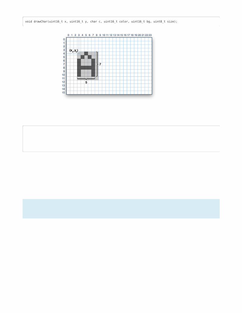
void drawChar(uint16_t x, uint16_t y, char c, uint16_t color, uint16_t bg, uint8_t size);
Text is very flexible but operates a bit differently. Instead of one procedure, the text size, color and
position are set up in separate functions and then the print() function is used — this makes it easy and
provides all of the same string and number formatting capabilities of the familiar Serial.print() function!
void setCursor(uint16_t x0, uint16_t y0);void setTextColor(uint16_t color);void setTextColor(uint16_t color, uint16_t backgroundcolor);void setTextSize(uint8_t size);void setTextWrap(boolean w);
Begin with setCursor(x, y), which will place the top left corner of the text wherever you please. Initially this
is set to (0,0) (the top-left corner of the screen). Then set the text color with setTextColor(color) — by
default this is white. Text is normally drawn “clear” — the open parts of each character show the original
background contents, but if you want the text to block out what’s underneath, a background color can be
specified as an optional second parameter tosetTextColor(). Finally, setTextSize(size) will multiply the
scale of the text by a given integer factor. Below you can see scales of 1 (the default), 2 and 3. It appears
blocky at larger sizes because we only ship the library with a single simple font, to save space.
� Note that the text background color is not supported for custom fonts. For these, you will need to
determine the text extents and explicitly draw a filled rectangle before drawing the text.
© Adafruit Industries https://learn.adafruit.com/adafruit-gfx-graphics-library Page 12 of 26
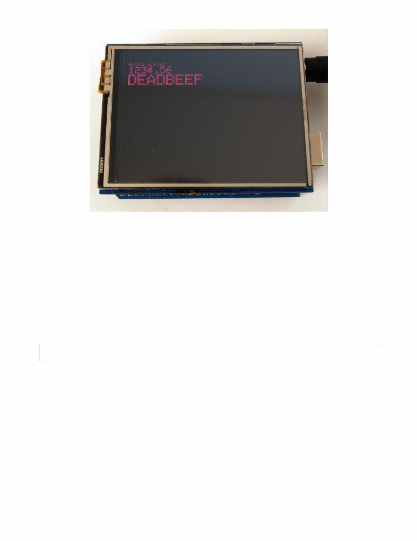
After setting everything up, you can use print() or println() — just like you do with Serial printing! For
example, to print a string, use print("Hello world") - that’s the first line of the image above. You can also
use print() for numbers and variables — the second line above is the output ofprint(1234.56) and the third
line is print(0xDEADBEEF, HEX).
By default, long lines of text are set to automatically “wrap” back to the leftmost column. To override this
behavior (so text will run off the right side of the display — useful for scrolling marquee effects), use
setTextWrap(false). The normal wrapping behavior is restored with setTextWrap(true).
See the “Using Fonts (https://adafru.it/kAf)” page for additional text features in the latest GFX library.
BitmapsYou can draw small monochrome (single color) bitmaps, good for sprites and other mini-animations or
icons:
void drawBitmap(int16_t x, int16_t y, uint8_t *bitmap, int16_t w, int16_t h, uint16_t color);
This issues a contiguous block of bits to the display, where each '1' bit sets the corresponding pixel to
'color,' while each '0' bit is skipped. x, y is the top-left corner where the bitmap is drawn, w, h are the width
and height in pixels.
The bitmap data must be located in program memory using the PROGMEM directive. This is a somewhat
advanced function and beginners are best advised to come back to this later. For an introduction, see
the Arduino tutorial on PROGMEM usage (https://adafru.it/aMw).
Here's a handy webtool for generating bitmap -> memorymaps (https://adafru.it/l3b)
Clearing or filling the screenThe fillScreen() function will set the entire display to a given color, erasing any existing content:
© Adafruit Industries https://learn.adafruit.com/adafruit-gfx-graphics-library Page 13 of 26

void fillScreen(uint16_t color);
© Adafruit Industries https://learn.adafruit.com/adafruit-gfx-graphics-library Page 14 of 26

Rotating the DisplayYou can also rotate your drawing. Note that this will not rotate what you already drew, but it will change
the coordinate system for any new drawing. This can be really handy if you had to turn your board or
display sideways or upside down to fit in a particular enclosure. In most cases this only needs to be done
once, inside setup().
We can only rotate 0, 90, 180 or 270 degrees - anything else is not possible in hardware and is too taxing
for an Arduino to calculate in software
void setRotation(uint8_t rotation);
The rotation parameter can be 0, 1, 2 or 3. For displays that are part of an Arduino shield, rotation value 0
sets the display to a portrait (tall) mode, with the USB jack at the top right. Rotation value 2 is also a
portrait mode, with the USB jack at the bottom left. Rotation 1 is landscape (wide) mode, with the USB jack
at the bottom right, while rotation 3 is also landscape, but with the USB jack at the top left.
For other displays, please try all 4 rotations to figure out how they end up rotating as the alignment will
vary depending on each display, in general the rotations move counter-clockwise
When rotating, the origin point (0,0) changes — the idea is that it should be arranged at the top-left of the
display for the other graphics functions to make consistent sense (and match all the function descriptions
above).
If you need to reference the size of the screen (which will change between portrait and landscape
modes), use width() and height().
uint16_t width(); uint16_t height();
© Adafruit Industries https://learn.adafruit.com/adafruit-gfx-graphics-library Page 15 of 26

Each returns the dimension (in pixels) of the corresponding axis, adjusted for the display’s current rotation
setting.
© Adafruit Industries https://learn.adafruit.com/adafruit-gfx-graphics-library Page 16 of 26

Using FontsMore recent versions of the Adafruit GFX library offer the ability to use alternate fonts besides the one
standard fixed-size and -spaced face that’s built in. Several alternate fonts are included, plus there’s the
ability to add new ones.
The included fonts are derived from the GNU
FreeFont (https://adafru.it/kAg) project. There are three faces:
“Serif” (reminiscent of Times New Roman), “Sans”
(reminiscent of Helvetica or Arial) and “Mono” (reminiscent of
Courier). Each is available in a few styles (bold, italic, etc.) and
sizes. The included fonts are in a bitmap format, not scalable
vectors, as it needs to work within the limitations of a small
microcontroller.
Located inside the “Fonts” folder inside Adafruit_GFX, the included files (as of this writing) are:
FreeMono12pt7b.h FreeSansBoldOblique12pt7b.hFreeMono18pt7b.h FreeSansBoldOblique18pt7b.hFreeMono24pt7b.h FreeSansBoldOblique24pt7b.hFreeMono9pt7b.h FreeSansBoldOblique9pt7b.hFreeMonoBold12pt7b.h FreeSansOblique12pt7b.hFreeMonoBold18pt7b.h FreeSansOblique18pt7b.hFreeMonoBold24pt7b.h FreeSansOblique24pt7b.hFreeMonoBold9pt7b.h FreeSansOblique9pt7b.hFreeMonoBoldOblique12pt7b.h FreeSerif12pt7b.hFreeMonoBoldOblique18pt7b.h FreeSerif18pt7b.hFreeMonoBoldOblique24pt7b.h FreeSerif24pt7b.hFreeMonoBoldOblique9pt7b.h FreeSerif9pt7b.hFreeMonoOblique12pt7b.h FreeSerifBold12pt7b.hFreeMonoOblique18pt7b.h FreeSerifBold18pt7b.hFreeMonoOblique24pt7b.h FreeSerifBold24pt7b.hFreeMonoOblique9pt7b.h FreeSerifBold9pt7b.hFreeSans12pt7b.h FreeSerifBoldItalic12pt7b.hFreeSans18pt7b.h FreeSerifBoldItalic18pt7b.hFreeSans24pt7b.h FreeSerifBoldItalic24pt7b.hFreeSans9pt7b.h FreeSerifBoldItalic9pt7b.hFreeSansBold12pt7b.h FreeSerifItalic12pt7b.hFreeSansBold18pt7b.h FreeSerifItalic18pt7b.hFreeSansBold24pt7b.h FreeSerifItalic24pt7b.hFreeSansBold9pt7b.h FreeSerifItalic9pt7b.h
Each filename starts with the face name (“FreeMono”, “FreeSerif”, etc.) followed by the style (“Bold”,
“Oblique”, none, etc.), font size in points (currently 9, 12, 18 and 24 point sizes are provided) and “7b” to
indicate that these contain 7-bit characters (ASCII codes “ ” through “~”); 8-bit fonts (supporting symbolsand/or international characters) are not yet provided but may come later.
Using GFX Fonts in Arduino SketchesAfter #including the Adafruit_GFX and display-specific libraries, include the font file(s) you plan to use in
your sketch. For example:
© Adafruit Industries https://learn.adafruit.com/adafruit-gfx-graphics-library Page 17 of 26
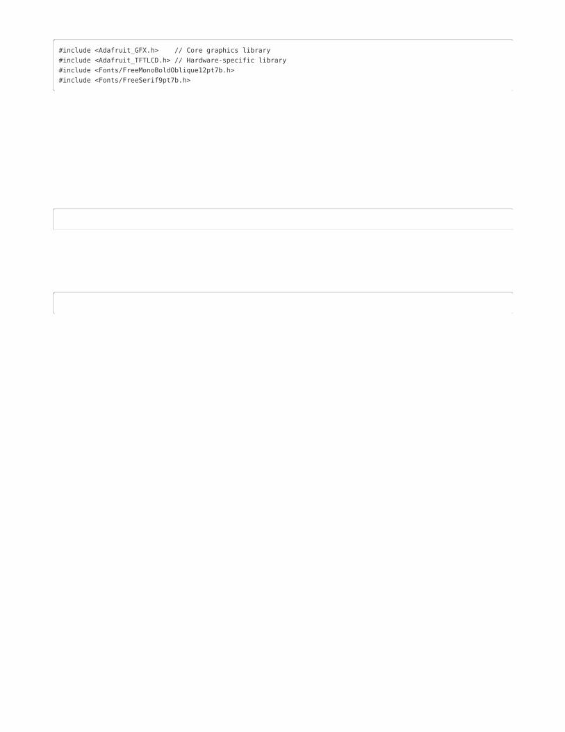
#include <Adafruit_GFX.h> // Core graphics library#include <Adafruit_TFTLCD.h> // Hardware-specific library#include <Fonts/FreeMonoBoldOblique12pt7b.h>#include <Fonts/FreeSerif9pt7b.h>
Each font takes up a bit of program space; larger fonts typically require more room. This is a finite
resource (about 32K max on an Arduino Uno for font data and all of your sketch code ), so choose
carefully. Too big and the code will refuse to compile (or in some edge cases, may compile but then won’t
upload to the board). If this happens, use fewer or smaller fonts, or use the standard built-in font.
Inside these .h files are several data structures, including one main font structure which will usually have
the same name as the font file (minus the .h). To select a font for subsequent graphics operations, use the
setFont() function, passing the address of this structure, such as:
tft.setFont(&FreeMonoBoldOblique12pt7b);
Subsequent calls to tft.print() will now use this font. Most other attributes that previously worked with the
built-in font (color, size, etc.) work similarly here.
To return to the standard fixed-size font, call setFont(), passing either NULL or no arguments:
tft.setFont();
Some text attributes behave a little differently with these new fonts. Not wanting to break compatibility
with existing code, the “classic” font continues to behave as before.
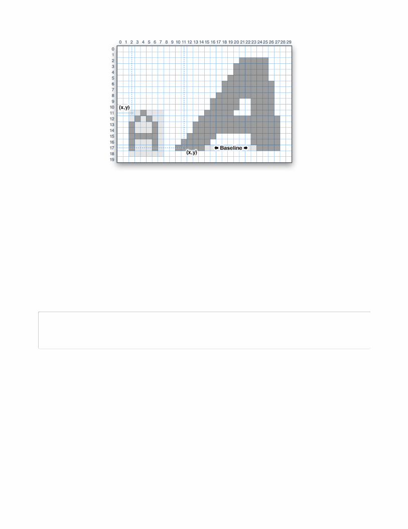
For example, whereas the cursor position when printing with the classic font identified the top-left cornerof the character cell, with new fonts the cursor position indicates the baseline — the bottom-most row —
of subsequent text. Characters may vary in size and width, and don’t necessarily begin at the exact cursor
column (as in below, this character starts one pixel left of the cursor, but others may be on or to the right
of it).
When switching between built-in and custom fonts, the library will automatically shift the cursor position
up or down 6 pixels as needed to continue along the same baseline.
© Adafruit Industries https://learn.adafruit.com/adafruit-gfx-graphics-library Page 18 of 26
One “gotcha” to be aware of with new fonts: there is no “background” color option…you can set this
value but it will be ignored.
This is on purpose and by design.The background color feature is sometimes used with the “classic” font to overwrite old screen
contents with new data. This only works because those characters are a uniform size; that won’t work
with proportionally-spaced fonts, where an indeterminate number of characters may overlap the same
region. The character-drawing function just isn’t set up to render that way (it would be prohibitive in
both memory and speed on AVRs, which are still supported by the library).
To replace previously-drawn text when using a custom font, either:
Use getTextBounds() to determine the smallest rectangle encompassing a string, erase the area
using fillRect(), then draw new text:
int16_t x1, y1;uint16_t w, h;
tft.getTextBounds(string, x, y, &x1, &y1, &w, &h);
getTextBounds expects a string, a starting cursor X&Y position (the current cursor position will not be
altered), and addresses of two signed and two unsigned 16-bit integers. These last four values will then
contain the upper-left corner and the width & height of the area covered by this text — these can then be
passed directly as arguments to fillRect().
This will unfortunately “blink” the text when erasing and redrawing, but is unavoidable. The old scheme of
drawing background pixels in the same pass only creates a new set of problems.
or:
Create a GFXcanvax1 object (an offscreen bitmap) for a fixed-size area, draw custom text in there
and copy to the screen using drawBitmap().
© Adafruit Industries https://learn.adafruit.com/adafruit-gfx-graphics-library Page 19 of 26
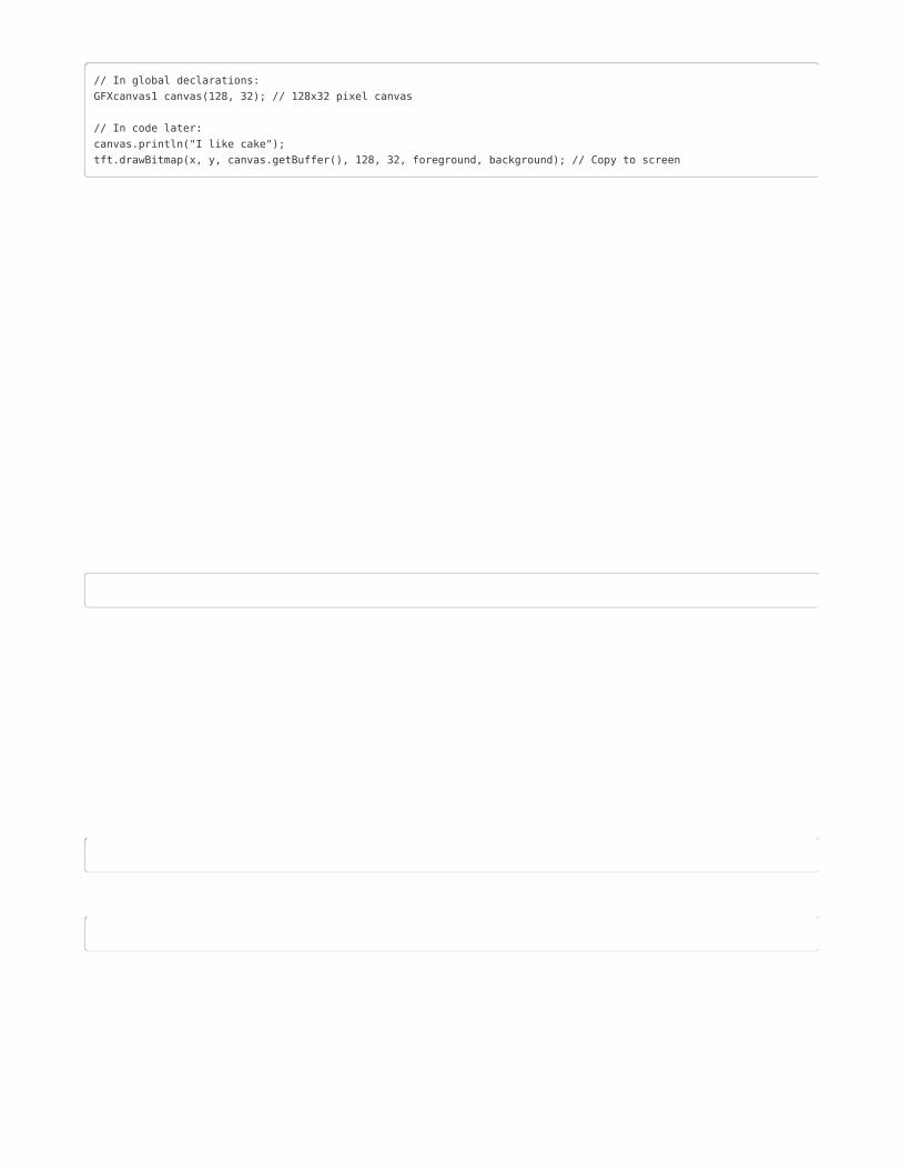
// In global declarations:GFXcanvas1 canvas(128, 32); // 128x32 pixel canvas
// In code later:canvas.println("I like cake");tft.drawBitmap(x, y, canvas.getBuffer(), 128, 32, foreground, background); // Copy to screen
This will be flicker-free but requires more RAM (about 512 bytes for the 128x32 pixel canvas shown
above), so it’s not always practical on AVR boards with only 2K. Arduino Mega or any 32-bit board should
manage fine.
Adding New FontsIf you want to create new font sizes not included with the library, or adapt entirely new fonts, we have a
command-line tool (in the “fontconvert” folder) for this. It should work on many Linux- or UNIX-like systems
(Raspberry Pi, Mac OS X, maybe Cygwin for Windows, among others).
Building this tool requires the gcc compiler and FreeType (https://adafru.it/kAh) library. Most Linux
distributions include both by default. For others, you may need to install developer tools and download
and build FreeType from the source (https://adafru.it/kAi). Then edit the Makefile to match your setup
before invoking “make”.
fontconvert expects at least two arguments: a font filename (such as a scalable TrueType vector font) and
a size, in points (72 points = 1 inch; the code presumes a screen resolution similar to the Adafruit 2.8" TFT
displays). The output should be redirected to a .h file…you can call this whatever you like but I try to be
somewhat descriptive:
./fontconvert myfont.ttf 12 > myfont12pt7b.h
The GNU FreeFont files are not included in the library repository but are
easily downloaded (https://adafru.it/kAj). Or you can convert most any font you like.
The name assigned to the font structure within this file is based on the input filename and font size, not
the output. This is why I recommend using descriptive filenames incorporating the font base name, size,
and "7p". Then the .h filename and font structure name can match.
The resulting .h file can be copied to the Adafruit_GFX/Fonts folder, or you can import the file as a new
tab in your Arduino sketch using the Sketch→Add File… command.
If in the Fonts folder, use this syntax when #including the file:
#include <Fonts/myfont12pt7b.h>
If a tab within your sketch, use this syntax:
#include "myfont12pt7b.h"
© Adafruit Industries https://learn.adafruit.com/adafruit-gfx-graphics-library Page 20 of 26

Loading Images
Loading .BMP images from an SD card (or the flash memory chip on Adafruit “Express” boards) is an
option for most of our color displays…though it’s not built into Adafruit_GFX and must be separately
installed.
The Adafruit_ImageReader library handles this task. It can be installed through the Arduino Library
Manager (Sketch→Include Library→Manage Libraries…). Enter “imageread” in the search field and the
library is easy to spot:
While you’re there, also look for the Adafruit_SPIFlash library and install it similarly.
There’s one more library required, but it can’t be installed through the Library Manager. The Adafruit fork
of the SdFat library needs to be downloaded as a .ZIP file, uncompressed and installed the old-school
Arduino library way (https://adafru.it/m3e).
https://adafru.it/Fml
https://adafru.it/Fml
© Adafruit Industries https://learn.adafruit.com/adafruit-gfx-graphics-library Page 21 of 26

Using the Adafruit_ImageReader LibraryThe syntax for using this library (and the separate installation above) are admittedly a bit peculiar…it’s a
side-effect of the way Arduino handles libraries. We purposefully did not roll this into Adafruit_GFX
because any mere mention of an SD card library will incur all of that library’s considerable memory
requirements…even if one’s sketch doesn’t use an SD card at all! A majority of graphics projects are self-
contained and don’t reference files from a card…not everybody needs this functionality.
There are several example sketches in the Adafruit_ImageReader/examples folder. It’s recommended
that you dissect these for ideas how to use the library in your own projects.
They all start with several #includes…
#include <Adafruit_GFX.h> // Core graphics library#include <Adafruit_ILI9341.h> // Hardware-specific library#include <SdFat.h> // SD card & FAT filesystem library#include <Adafruit_SPIFlash.h> // SPI / QSPI flash library#include <Adafruit_ImageReader.h> // Image-reading functions
One of these lines may vary from one example to the next, depending which display hardware it’s written
to support. Above we see it being used with the Adafruit_ILI9341 display library required of certain shields,
FeatherWings or breakout boards. Others examples reference Adafruit_HX8357, Adafruit_ST7735, or
other color TFT or OLED display libraries…use the right one for the hardware you have.
Most of the examples can work from either an SD card, or the small flash storage drive that’s on certain
Adafruit “Express” boards. The code to initialize one or the other is a little different, and the examples
check whether USE_SD_CARD is #defined to select one method vs. the other. If you know for a fact that
your own project only needs to run on one type or the other, you really only need the corresponding
initialization.
For SD card use, these two globals are declared:
SdFat SD; // SD card filesystem Adafruit_ImageReader reader(SD); // Image-reader object, pass in SD filesys
For a flash filesystem, there are some special declarations made that help us locate the flash device on
different Express boards, then declare three globals:
// SPI or QSPI flash filesystem (i.e. CIRCUITPY drive) #if defined(__SAMD51__) || defined(NRF52840_XXAA) Adafruit_FlashTransport_QSPI flashTransport(PIN_QSPI_SCK, PIN_QSPI_CS, PIN_QSPI_IO0, PIN_QSPI_IO1, PIN_QSPI_IO2, PIN_QSPI_IO3); #else #if (SPI_INTERFACES_COUNT == 1) Adafruit_FlashTransport_SPI flashTransport(SS, &SPI); #else Adafruit_FlashTransport_SPI flashTransport(SS1, &SPI1); #endif #endif Adafruit_SPIFlash flash(&flashTransport); FatFileSystem filesys; Adafruit_ImageReader reader(filesys); // Image-reader, pass in flash filesys
© Adafruit Industries https://learn.adafruit.com/adafruit-gfx-graphics-library Page 22 of 26
The “reader” object will be used to access the image-loading functions later.
Then…we declare a display object (called “tft” in most of the examples) the usual way…for example, with
the 2.8 inch TFT touch shield for Arduino, it’s:
#define SD_CS 4 // SD card select pin#define TFT_CS 10 // TFT select pin#define TFT_DC 9 // TFT display/command pin
Adafruit_ILI9341 tft = Adafruit_ILI9341(TFT_CS, TFT_DC);
That all takes place in the global variable section, even before the setup() function.
Now we need to do some work in setup(), and again it’s different for SD cards vs. flash filesystems…
For SD card use, it might look like this:
if(!SD.begin(SD_CS, SD_SCK_MHZ(25))) { // ESP32 requires 25 MHz limit Serial.println(F("SD begin() failed")); for(;;); // Fatal error, do not continue }
This example is providing some very basic error handling…checking the return status of SD.begin() and
printing a message to the Serial Monitor if there’s a problem.
Using a flash filesystem instead requires two steps:
if(!flash.begin()) { Serial.println(F("flash begin() failed")); for(;;); } if(!filesys.begin(&flash)) { Serial.println(F("filesys begin() failed")); for(;;); }
All other code is now the same regardless whether using an SD card or flash. That either/or setup
required some extra steps but it’s all smooth sailing now…
After the SD (or flash) and TFT’s begin() functions have been called, you can then call
reader.drawBMP() to load a BMP image from the card to the screen:
ImageReturnCode stat;stat = reader.drawBMP("/purple.bmp", tft, 0, 0);
This accepts four arguments:
A filename in “8.3” format (you shouldn’t need to provide an absolute path (the leading “/”), but there
are some issues with the SD library on some cutting-edge boards like the ESP32, so go ahead and
include this for good measure).
The display object where the image will be drawn (e.g. “tft”). This is the weird syntax previouslymentioned…rather than tft.drawBMP(), it’s reader.drawBMP(tft), because reasons.An X and Y coordinate where the top-left corner of the image is positioned (this doesn’t need to be
within screen bounds…the library will clip the image as it’s loaded). 0, 0 will draw the image at the
© Adafruit Industries https://learn.adafruit.com/adafruit-gfx-graphics-library Page 23 of 26
top-left corner…so if the image dimensions match the screen dimensions, it will fill the entire screen.
This function returns a value of type ImageReturnCode , which you can either ignore or use it to provide
some diagnostic functionality. Possible values are:
IMAGE_SUCCESS — Image loaded successfully (or was clipped fully off screen, still considered
“successful” in that there was no error).
IMAGE_ERR_FILE_NOT_FOUND — Could not open the requested file (check spelling, confirm file
actually exists on the card, make sure it conforms to “8.3” file naming convention (e.g.
“filename.bmp”).
IMAGE_ERR_FORMAT — Not a supported image format. Currently only uncompressed 24-bit color
BMPs are supported (more will likely be added over time).
IMAGE_ERR_MALLOC — Could not allocate memory for operation (drawBMP() won’t generate this
error, but other ImageReader functions might).
Rather than dealing with these values yourself, you can optionally call a function to display a basic
diagnostic message to the Serial console:
reader.printStatus(stat);
If you need to know the size of a BMP image without actually loading it, there’s the bmpDimensions()function:
int32_t width, height;stat = reader.bmpDimensions("/parrot.bmp", &width, &height);
This accepts three arguments:
A filename, same rules as the drawBMP() function.
Pointers to two 32-bit integers. On successful completion, their contents will be set to the image
width and height in pixels. On any error these values should be ignored (they’re left uninitialized).
This function returns an ImageReturnCode as explained with the drawBMP() function above.
Loading and Using Images in RAMDepending on image size and other factors, loading an image from SD card to screen may take several
seconds. Small images…those that can fit entirely in RAM…can be loaded once and used repeatedly. This
can be handy for frequently-used icons or sprites, as it’s usually much easier than converting and
embedding an image as an array directly in one’s code…a horrible process.
This introduces another ImageReader function plus a new object type, Adafruit_Image :
Adafruit_Image img;stat = reader.loadBMP("/wales.bmp", img);
loadBMP() accepts two arguments:
A filename, same rules as the previous functions.
An Adafruit_Image object. This is a slightly more flexible type than the bitmaps used by a few
drawing functions in the GFX library.
© Adafruit Industries https://learn.adafruit.com/adafruit-gfx-graphics-library Page 24 of 26

This returns an ImageReturnCode as previously described. If an image is too large to fit in available RAM,
a value of IMAGE_ERR_MALLOC will be returned. Color images require two bytes per pixel…for example,
a 100x25 pixel image would need 100*25*2 = 5,000 bytes RAM.
On success, the img object will contain the image in RAM.
The loadBMP() function is useful only on microcontrollers with considerable RAM, like the Adafruit “M0”
and “M4” boards, or ESP32. Small devices like the Arduino Uno just can’t cut it. It might be marginallyuseful on the Arduino Mega with very small images.
After loading, use the img.draw() function to display an image on the screen:
img.draw(tft, x, y);
This accepts three arguments:
A display object (e.g. “tft” in most of the examples), similar to how drawBMP() worked.
An X and Y coordinate for the upper-left corner of the image on the screen, again similar to
drawBMP() .
We use img.draw(tft,…) rather than tft.drawRGBBitmap(…) (or other bitmap-drawing functions in the
Adafruit_GFX library) because in the future we plan to add more flexibility with regard to image file
formats and types. The Adafruit_Image object “understands” a bit about the image that’s been loaded
and will call the appropriate bitmap-rendering function automatically, you won’t have to handle each
separate case on your own.
If the image failed to load for any reason, img.draw() can still be called, it just won’t do anything. But at
least the sketch won’t crash.
© Adafruit Industries https://learn.adafruit.com/adafruit-gfx-graphics-library Page 25 of 26

© Adafruit Industries Last Updated: 2020-11-19 04:53:27 PM EST Page 26 of 26


