Soraya Terrab,1 Alexander M. Watson,1 Christopher Roath,3 Juliet T. Gopinath,2,* and Victor M. Bright1
1Department of Mechanical Engineering, University of Colorado, Boulder, Colorado 80309, USA 2Department of Electrical, Computer, and Energy Engineering, Boulder, Colorado 80309, USA
3VSI Parylene, 325 Interlocken Pkwy, Building C, Broomfield, Colorado 80021, USA *[email protected]
Abstract: An adaptive electrowetting-based element with focusing and steering capability has been demonstrated in a monolithic design. Curvature and tip-tilt variation have been demonstrated using low voltages. A steering range of up to 4.3° and lens tuning of 18 diopters have been measured at 30 V DC and 21 V DC, respectively.
OCIS codes: (230.0230) Optical devices; (010.1080) Active or adaptive optics; (230.5480) Prisms; (080.3630) Lenses
References and links
1. R. Tyson, Principles of Adaptive Optics (Academic Press, 1991). 2. U. Efron, Spatial Light Modulator Technology: Materials, Devices and Applications (Marcel Dekker, 1995). 3. R. D. Niederriter, A. M. Watson, R. N. Zahreddine, C. J. Cogswell, R. H. Cormack, V. M. Bright, and J. T.
Gopinath, “Electrowetting lenses for compensating phase and curvature distortion in arrayed laser systems,” Appl. Opt. 52(14), 3172–3177 (2013).
4. F. Krogmann, W. Moench, and H. Zappe, “A MEMS-Based Variable Micro-Lens System,” J. Opt. A: Pure Appl. Opt. 8(330), S330–S336 (2006).
5. C. Li and H. Jiang, “Electrowetting-driven variable-focus microlens on flexible surfaces,” Appl. Phys. Lett. 100(23), 231105 (2012).
6. S. W. Seo, S. Han, J. H. Seo, Y. M. Kim, M. S. Kang, N. K. Min, W. B. Choi, and M. Y. Sung, “Microelectromechanical-System-Based Variable-Focus Liquid Lens for Capsule Endoscopes,” Jpn. J. Appl. Phys. 48(5), 052404 (2009).
7. S. Kuiper and B. H. W. Hendriks, “Variable-focus liquid lens for miniature cameras,” Appl. Phys. Lett. 85, 1128–1130 (2004).
8. J. Bae, Y.-S. Choi, K. Choi, Y. Kim, Y. Kwon, H. Song, E. Kim, S. Choi, J. Lee, and S. Lee, “Arrayed beam steering device for advanced 3D displays,” Proc. SPIE 8616, 86160H (2013).
9. Y. Kwon, Y. Choi, K. Choi, Y. Kim, S. Choi, and J. Lee, “Development of micro variable optics array,” in Proceedings of IEEE Microelectromechanical Systems (MEMS 2014), pp.72–75.
10. L. Hou, J. Zhang, N. Smith, J. Yang, and J. Heikenfeld, “A full description of a scalable microfabrication process for arrayed electrowetting microprisms,” J. Micromech. Microeng. 20(1), 015044 (2010).
11. J. C. Heikenfeld, N. R. Smith, B. Sun, K. Zhou, L. Hou, Y. Lao, and B. Raj, “Flat electrowetting optics and displays,” Proc. SPIE 6887, 688705 (2008).
12. K. Zhou, J. Heikenfeld, K. A. Dean, E. M. Howard, and M. R. Johnson, “A full description of a simple and scalable fabrication process for electrowetting displays,” J. Micromech. Microeng. 19(6), 065029 (2009).
13. Y. Kim, Y.-S. Choi, K. Choi, Y. Kwon, J. Bae, A. Morozov, and H.-S. Lee, “Measurement of the optical characteristics of electro-wetting prism array for three-dimensional display,” Proc. SPIE 8643, 864305 (2013).
14. S. Deladi, J. F. Suijver, Y. S. Shi, K. Shahzad, B. M. De Boer, a. J. J. Rademakers, C. Van Der Vleuten, L. Jankovic, E. Bongers, E. Harks, and S. Kuiper, “Miniaturized ultrasound scanner by electrowetting,” Appl. Phys. Lett. 97, 19–22 (2010).
15. C. Liu, L. Li, and Q.-H. Wang, “Liquid prism for beam tracking and steering,” Opt. Eng. 51(11), 114002 (2012). 16. N. R. Smith, D. C. Abeysinghe, J. W. Haus, and J. Heikenfeld, “Agile wide-angle beam steering with
electrowetting microprisms,” Opt. Express 14(14), 6557–6563 (2006). 17. L. Hou, N. R. Smith, and J. Heikenfeld, “Electrowetting manipulation of any optical film,” Appl. Phys. Lett.
90(25), 251114 (2007). 18. J. Cheng and C.-L. Chen, “Adaptive beam tracking and steering via electrowetting-controlled liquid prism,”
Appl. Phys. Lett. 99(19), 191108 (2011). 19. T. Fuji and T. Fukuchi, Laser remote sensing (CRC Press, 2005). 20. B. N. Ozbay, J. T. Losacco, R. Cormack, R. Weir, V. M. Bright, J. T. Gopinath, D. Restrepo, and E. A. Gibson,
“Miniaturized fiber-coupled confocal fluorescence microscope with an electrowetting variable focus lens using no moving parts,” Opt. Lett. 40(11), 2553–2556 (2015).
21. F. Mugele and J.-C. Baret, “Electrowetting: from basics to applications,” J. Phys. Condens. Matter 17(28), R705–R774 (2005).
22. T. Roques-Carmes, S. Palmier, R. Hayes, and L. J. M. Schlangen, The effect of the oil/water interfacial tension on electrowetting driven fluid motion,” Eng. Asp. 267(1–3), 56–63 (2005).
23. A. M. Watson, K. Dease, S. Terrab, C. Roath, J. T. Gopinath, and V. M. Bright, “Focus-tunable low-power electrowetting lenses with thin parylene films,” Appl. Opt. 54(20), 6224–6229 (2015).
1. Introduction
Electrowetting-based optical devices provide an advantageous and versatile alternative to conventional adaptive optics [1]. In lieu of moving parts, they are liquid-based and compact and can be integrated in small-scale optical systems. They operate under low voltages and have been demonstrated with kHz speeds in contrast to typical spatial light modulators [2]. In addition, electrowetting-based optics allow beam transmission rather than reflection, which provides an advantage in comparison to MEMS-based and deformable mirrors [3]. Electrowetting lenses have been demonstrated with high optical quality [3,4] and have been implemented in flexible films [5], endoscopes [6], and cameras [7]. Electrowetting prism arrays have a wide range of applications, including imaging displays [8–13], scanners [14], and solar tracking systems [15]. For other beam steering applications, single, stand-alone electrowetting prisms have been demonstrated with single-liquid [16], two-liquid [17,18], and three-liquid [15] configurations.
Adaptive optics and beam steering are critical for applications such as imaging, free space optical communications, and LIDAR systems [19]. To meet this need, we have demonstrated an innovative single, adaptive optical element that is electrically tunable both in curvature and tip-tilt. The lens-prism element provides a simple and versatile adaptive optics solution. The dual-function, single element device is monolithic, operates based on electrowetting, and can be easily integrated and miniaturized in advanced optical systems, such as medical diagnostics [20].
2. Electrowetting background
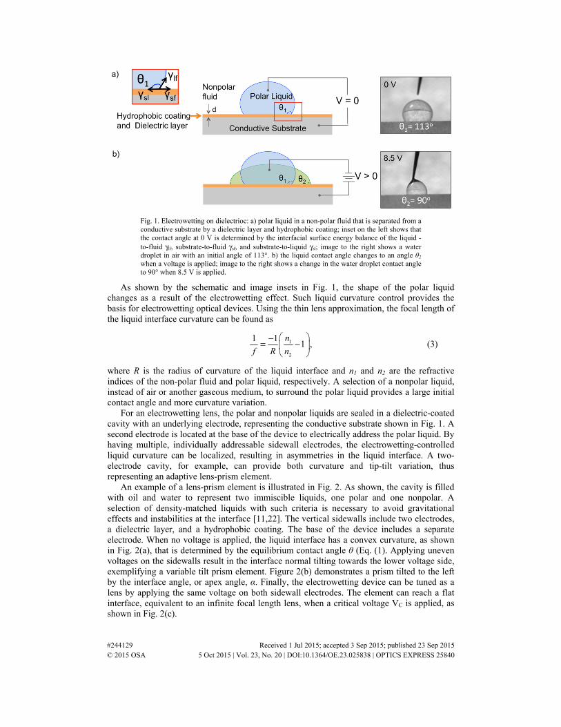
Electrowetting describes the change in a liquid’s shape under an applied voltage. Figure 1(a) shows a polar liquid droplet in a non-polar fluid, which sits on a conductive substrate topped with a hydrophobic coating and dielectric layer. The interfacial surface energy balance of the non-polar fluid, polar liquid, and substrate governs the initial contact angle θ1, as shown by the Fig. 1(a) inset. The Young equation defines θ1 as
1cos ,sf sl
lf
γ γθ
γ−
= (1)
where γ represents the interfacial surface energy and the s, f, l subscripts denote the solid, fluid, and liquid media, respectively. An applied voltage between the polar liquid and the substrate induces a change in the liquid contact angle due to an electrostatic force. As shown in Fig. 1(b), the contact angle changes from θ1 to θ2, which can be solved by the Lippmann-Young equation:
22 1cos cos ,
2d
lf
Vd
εθ θγ
= + (2)
where εd is the dielectric permittivity, d is the thickness of the dielectric, and V is the applied voltage [21].
Fig. 1. Electrowetting on dielectrioc: a) polar liquid in a non-polar fluid that is separated from a conductive substrate by a dielectric layer and hydrophobic coating; inset on the left shows that the contact angle at 0 V is determined by the interfacial surface energy balance of the liquid -to-fluid γlf, substrate-to-fluid γsf, and substrate-to-liquid γsl; image to the right shows a water droplet in air with an initial angle of 113°. b) the liquid contact angle changes to an angle θ2 when a voltage is applied; image to the right shows a change in the water droplet contact angle to 90° when 8.5 V is applied.
As shown by the schematic and image insets in Fig. 1, the shape of the polar liquid changes as a result of the electrowetting effect. Such liquid curvature control provides the basis for electrowetting optical devices. Using the thin lens approximation, the focal length of the liquid interface curvature can be found as
1
2
1 11 ,
n
f R n
−= −
(3)
where R is the radius of curvature of the liquid interface and n1 and n2 are the refractive indices of the non-polar fluid and polar liquid, respectively. A selection of a nonpolar liquid, instead of air or another gaseous medium, to surround the polar liquid provides a large initial contact angle and more curvature variation.
For an electrowetting lens, the polar and nonpolar liquids are sealed in a dielectric-coated cavity with an underlying electrode, representing the conductive substrate shown in Fig. 1. A second electrode is located at the base of the device to electrically address the polar liquid. By having multiple, individually addressable sidewall electrodes, the electrowetting-controlled liquid curvature can be localized, resulting in asymmetries in the liquid interface. A two-electrode cavity, for example, can provide both curvature and tip-tilt variation, thus representing an adaptive lens-prism element.
An example of a lens-prism element is illustrated in Fig. 2. As shown, the cavity is filled with oil and water to represent two immiscible liquids, one polar and one nonpolar. A selection of density-matched liquids with such criteria is necessary to avoid gravitational effects and instabilities at the interface [11,22]. The vertical sidewalls include two electrodes, a dielectric layer, and a hydrophobic coating. The base of the device includes a separate electrode. When no voltage is applied, the liquid interface has a convex curvature, as shown in Fig. 2(a), that is determined by the equilibrium contact angle θ (Eq. (1). Applying uneven voltages on the sidewalls result in the interface normal tilting towards the lower voltage side, exemplifying a variable tilt prism element. Figure 2(b) demonstrates a prism tilted to the left by the interface angle, or apex angle, α. Finally, the electrowetting device can be tuned as a lens by applying the same voltage on both sidewall electrodes. The element can reach a flat interface, equivalent to an infinite focal length lens, when a critical voltage VC is applied, as shown in Fig. 2(c).
Fig. 2. An oil-water electrowetting lens-prism element with an electrode on the base and a hydrophobic coating, dielectric layer, and two electrodes along the sidewalls. Voltage VL and VR denote the applied voltage on the left and right sidewall electrodes, respectively, with the following cases: a) oil-water interface curvature when no voltage is applied, contact angle θ is shown; b) liquid interface tilted to the left by a prism apex angle α when VL >VR ; c) flat liquid interface when a critical voltage VC is applied on both sidewalls.
For the liquid housing, a cylindrical geometry is preferred to a rectangular one as it eliminates corner effects that could skew the lens quality. A transparent design is also necessary thus requiring transparent conductive oxides for the electrodes. A high-quality, conformal, pinhole-free dielectric is important in avoiding liquid permeation and dielectric breakdown and fatigue. The dielectric is therefore crucial in attaining device reliability. A hydrophobic coating, applied on top of the dielectric, ensures a large initial contact angle, and also prevents the liquid from pinning onto the sidewall. In addition to selecting liquids with the aforementioned properties, a large-ion aqueous solution is needed to prevent ion injection into the dielectric [23].
3. Device fabrication
A glass tube with 6 mm inner diameter and a height of 10 mm is selected as the substrate. After rinsing the tube with acetone and isopropyl alcohol and drying it with N2 gas, Kapton strips (~1 mm wide) are placed on opposite ends, along the cylinder diameter to mask the electrode deposition, and on the lower rim. This effectively splits the tube sidewall electrodes and prevents deposition on the tube base, as illustrated in Fig. 3(a). Indium-zinc-oxide (IZO) is selected as the transparent conductive oxide for the underlying electrode. It is sputtered onto the masked glass tube in a DC sputter system [Fig. 3(b)]. After first achieving a base pressure of 2 μTorr, Argon gas is pumped into the chamber at a pressure of 5 mTorr. Once Ar is ionized at 120 W of power, IZO is sputtered onto the sample for a deposition thickness of ~300 nm, as measured by a quartz crystal microbalance. The mean free path length at this chamber pressure is much smaller than the distance between IZO target and substrate, enabling diffuse sputtering and a conformal coating from inside to outside of the tube. The process parameters result in an IZO sheet resistance of 23.4 Ω/sq.
Before depositing the thin film dielectrics, the glass tube is cleaned and the exterior masked with Kapton tape to provide electrode contact from outside the tube after the dielectric deposition. Parylene C (1 μm) is deposited in a vapor-phase, low-vacuum system at a company (VSI Parylene). The samples are then dip-coated in a 1:20 solution of Dupont’s Teflon AF1600: Fluorinert FC-40 for the hydrophobic coating. To cure the Teflon above its glass transition temperature of 165°C, the samples are heated in an oven at 120°C for 10 min and then 172°C + 2°C for 20 min. The inset in Fig. 3(c) shows the thin film layers on the device.
The exterior Kapton tape is removed and the tube sample is centered on an indium-tin-oxide (ITO)-coated glass substrate (Sigma Aldrich, 30-60 Ω/sq) cut down to 10 mm x 10 mm
squares. Masterbond EP30-2 is applied about the tube base to bond the tube to the ITO square, as shown in Fig. 3(d).
Fig. 3. Device fabrication: a) Kapton tape masking of glass tube; b) IZO sputtering for base electrode; c) Parylene vapor-phase deposition and Teflon dip-coating; d) sample bonding onto ITO-coated glass substrate.
Finally, the samples are filled with dodecane oil (Sigma Aldrich, nd = 1.420) and an aqueous solution (nd = 1.333) [23]. A 1 wt.% sodium-dodecyl sulfate (SDS) solution is selected as the polar liquid for two reasons: its surfactant nature and its large anion. The SDS surfactant reduces surface tension between water and oil, which enables low-voltage interface tuning as governed by Eq. (2). Applying a positive voltage to the sidewalls ensures the large dodecyl sulfate anions are drawn to the thin film dielectrics. The larger ion size helps to prevent leakage through the dielectric. Consequently, device operation with low DC voltages and the selected liquid prevents dielectric fatigue and breakdown, ensuring reliable tuning.
4. Experimental setup and results
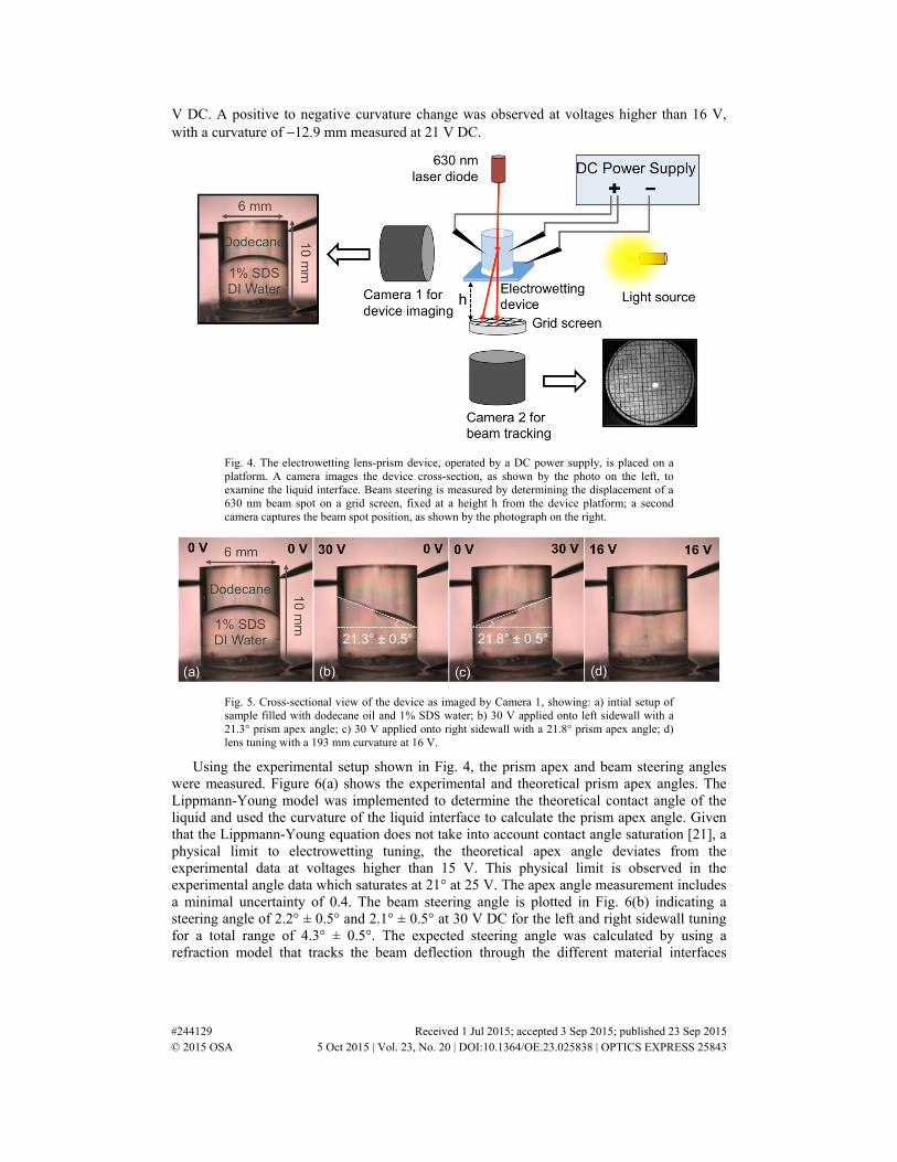
After device assembly, we characterized the curvature and tip-tilt range in order to demonstrate the adaptive lens-prism operation. The lens-prism element was placed on a suspended platform with three needle probes, connected to a DC power supply, that addressed the two sidewall electrodes and the base electrode, as illustrated in Fig. 4. Two cameras were included, Camera 1 and Camera 2 as shown in Fig. 4, to image the device and beam spot, respectively. Camera 1 focused on the device cross-section, illuminated by a backlight, and was used to capture the liquid interface at different voltage configurations. The image on the left in Fig. 4 shows the device in its initial state with no voltage applied. For tip-tilt characterization, we referred to Camera 1 images to determine the tilted liquid interface angle α and measured beam steering separately. The beam spot from a 630 nm laser diode that was normally incident onto the device was projected onto a grid screen. Camera 2 was used to image the grid screen and track the change in beam spot position when the device was tuned. The steering angle was determined from the arctangent of the ratio of the beam spot displacement and the fixed height h between the grid screen and the device.
The device operation for different voltage combinations is shown in Fig. 5. The liquid interface formed by the boundary of dodecane oil and 1% SDS aqueous solution initially has a curvature of 5.3 mm. Up to 30 V DC is applied on the left or right sidewalls while keeping the opposite sidewall at 0 V. The liquid interface angle reaches up to 21.3° ± 0.5° and 21.8° ± 0.5° as shown in Fig. 5(b) and Fig. 5(c), respectively. When applying the same voltage on both sidewalls, the liquid curvature can be varied from 5.3 mm to 195 mm when applying 16
V DC. A positive to negative curvature change was observed at voltages higher than 16 V, with a curvature of −12.9 mm measured at 21 V DC.
Fig. 4. The electrowetting lens-prism device, operated by a DC power supply, is placed on a platform. A camera images the device cross-section, as shown by the photo on the left, to examine the liquid interface. Beam steering is measured by determining the displacement of a 630 nm beam spot on a grid screen, fixed at a height h from the device platform; a second camera captures the beam spot position, as shown by the photograph on the right.
Fig. 5. Cross-sectional view of the device as imaged by Camera 1, showing: a) intial setup of sample filled with dodecane oil and 1% SDS water; b) 30 V applied onto left sidewall with a 21.3° prism apex angle; c) 30 V applied onto right sidewall with a 21.8° prism apex angle; d) lens tuning with a 193 mm curvature at 16 V.
Using the experimental setup shown in Fig. 4, the prism apex and beam steering angles were measured. Figure 6(a) shows the experimental and theoretical prism apex angles. The Lippmann-Young model was implemented to determine the theoretical contact angle of the liquid and used the curvature of the liquid interface to calculate the prism apex angle. Given that the Lippmann-Young equation does not take into account contact angle saturation [21], a physical limit to electrowetting tuning, the theoretical apex angle deviates from the experimental data at voltages higher than 15 V. This physical limit is observed in the experimental angle data which saturates at 21° at 25 V. The apex angle measurement includes a minimal uncertainty of 0.4. The beam steering angle is plotted in Fig. 6(b) indicating a steering angle of 2.2° ± 0.5° and 2.1° ± 0.5° at 30 V DC for the left and right sidewall tuning for a total range of 4.3° ± 0.5°. The expected steering angle was calculated by using a refraction model that tracks the beam deflection through the different material interfaces
given the specific apex angle measured. As shown by the plot in Fig. 6(b), the experimental and calculated beam steering angles are in agreement.
Fig. 6. Electrowetting prism results: a) prism apex angle as a function of voltage for left and right sidewall tuning, including measured data with ± 0.4° uncertainty error and the expected steering from the Lippmann-Young model; b) prism steering from measured beam spot displacement with ± 0.5° uncertainty and the expected steering from the electrowetting prism refraction model that uses measured prism apex angle.
The electrowetting device was also tested as a lens by applying the same voltage on both sidewalls. Figure 7(a) shows the liquid contact angle variation under applied voltage with error bars indicating ± 1.6° measurement uncertainty. The expected contact angle from the Lippmann-Young model is plotted and indicates an agreement with the experimental data. The dioptric power, calculated from Eq. (3) by using R = r/cos θ [device radius r = 3 mm], is demonstrated in Fig. 7(b). The dioptric power ranges from 12.8 m−1 to −5.2 m−1, with ± 0.6m-1 average measurement uncertainty, when applying up to 21 V DC. The switch from positive to negative lens occurs at 16 V, approximately equivalent to the critical voltage VC for an infinite focal length lens as described in Fig. 2(c).
Fig. 7. Electrowetting lens tuning of an oil/water lens-prism device: a) liquid contact angle from experiments with ± 1.6° measurement uncertainty and Lippmann-Young Model; b) dioptric power determined from the curvature of the liquid interface ( ± 0.6 m-1 average measurement uncertainty) from voltages 0-21 V, indicating a change from positive to negative lens at 16 V.
We have shown a simple yet effective way to pattern electrodes in a glass tube that resulted in a monolithic design for an electrowetting-based lens-prism element. This design is advantageous for fully-integrated optical systems and directly targets small-scale complex optics. The adaptive lens-prism device provides up to 4.3° steering range at 30 V DC and a dioptric power range of 12.8 m−1 to −5.2 m−1 at 21 V DC, demonstrating a low-voltage, dual-function adaptive optical element. Additionally, our data agrees with the Lippmann-Young and refraction models, validating our experimental work and device operation.
The device can be optimized to provide enhanced steering range and dioptric power. The refraction model indicated the ± 2° steering range due to the close-valued refractive indices of oil and water. A selection of higher-contrast index liquids will further improve the steering range. Additionally, preliminary Zemax modeling has shown that adding a diverging lens after the electrowetting device will maximize the steering capability. Furthermore, the dioptric power can be improved by having a larger initial contact angle, which can be controlled by modifying the surface chemistry or the top layer of the dielectric stack.
Acknowledgments
The work was supported by the Butcher Foundation and the National Science Foundation (NSF) IDBR DBI-1353757. The authors are grateful for the technical assistance of Professor Robert McLeod, Dr. Darren Foreman, Yehor Novikov, Stephen Skiffington, Kevin Dease, Robert Niederriter, and Nathan Eigenfeld. Publication of this article was funded by the University of Colorado Boulder Libraries Open Access Fund.